WO2020183978A1 - Instrument médical - Google Patents
Instrument médical Download PDFInfo
- Publication number
- WO2020183978A1 WO2020183978A1 PCT/JP2020/003978 JP2020003978W WO2020183978A1 WO 2020183978 A1 WO2020183978 A1 WO 2020183978A1 JP 2020003978 W JP2020003978 W JP 2020003978W WO 2020183978 A1 WO2020183978 A1 WO 2020183978A1
- Authority
- WO
- WIPO (PCT)
- Prior art keywords
- tubular portion
- medical device
- tubular
- connecting member
- holder
- Prior art date
Links
Images


Classifications
-
- A—HUMAN NECESSITIES
- A61—MEDICAL OR VETERINARY SCIENCE; HYGIENE
- A61M—DEVICES FOR INTRODUCING MEDIA INTO, OR ONTO, THE BODY; DEVICES FOR TRANSDUCING BODY MEDIA OR FOR TAKING MEDIA FROM THE BODY; DEVICES FOR PRODUCING OR ENDING SLEEP OR STUPOR
- A61M39/00—Tubes, tube connectors, tube couplings, valves, access sites or the like, specially adapted for medical use
- A61M39/10—Tube connectors; Tube couplings
- A61M39/1011—Locking means for securing connection; Additional tamper safeties
-
- A—HUMAN NECESSITIES
- A61—MEDICAL OR VETERINARY SCIENCE; HYGIENE
- A61M—DEVICES FOR INTRODUCING MEDIA INTO, OR ONTO, THE BODY; DEVICES FOR TRANSDUCING BODY MEDIA OR FOR TAKING MEDIA FROM THE BODY; DEVICES FOR PRODUCING OR ENDING SLEEP OR STUPOR
- A61M39/00—Tubes, tube connectors, tube couplings, valves, access sites or the like, specially adapted for medical use
- A61M39/10—Tube connectors; Tube couplings
- A61M39/1055—Rotating or swivel joints
-
- A—HUMAN NECESSITIES
- A61—MEDICAL OR VETERINARY SCIENCE; HYGIENE
- A61M—DEVICES FOR INTRODUCING MEDIA INTO, OR ONTO, THE BODY; DEVICES FOR TRANSDUCING BODY MEDIA OR FOR TAKING MEDIA FROM THE BODY; DEVICES FOR PRODUCING OR ENDING SLEEP OR STUPOR
- A61M39/00—Tubes, tube connectors, tube couplings, valves, access sites or the like, specially adapted for medical use
- A61M39/22—Valves or arrangement of valves
- A61M39/223—Multiway valves
-
- A—HUMAN NECESSITIES
- A61—MEDICAL OR VETERINARY SCIENCE; HYGIENE
- A61M—DEVICES FOR INTRODUCING MEDIA INTO, OR ONTO, THE BODY; DEVICES FOR TRANSDUCING BODY MEDIA OR FOR TAKING MEDIA FROM THE BODY; DEVICES FOR PRODUCING OR ENDING SLEEP OR STUPOR
- A61M39/00—Tubes, tube connectors, tube couplings, valves, access sites or the like, specially adapted for medical use
- A61M39/10—Tube connectors; Tube couplings
- A61M2039/1072—Tube connectors; Tube couplings with a septum present in the connector
-
- A—HUMAN NECESSITIES
- A61—MEDICAL OR VETERINARY SCIENCE; HYGIENE
- A61M—DEVICES FOR INTRODUCING MEDIA INTO, OR ONTO, THE BODY; DEVICES FOR TRANSDUCING BODY MEDIA OR FOR TAKING MEDIA FROM THE BODY; DEVICES FOR PRODUCING OR ENDING SLEEP OR STUPOR
- A61M39/00—Tubes, tube connectors, tube couplings, valves, access sites or the like, specially adapted for medical use
- A61M39/10—Tube connectors; Tube couplings
- A61M2039/1077—Adapters, e.g. couplings adapting a connector to one or several other connectors
-
- A—HUMAN NECESSITIES
- A61—MEDICAL OR VETERINARY SCIENCE; HYGIENE
- A61M—DEVICES FOR INTRODUCING MEDIA INTO, OR ONTO, THE BODY; DEVICES FOR TRANSDUCING BODY MEDIA OR FOR TAKING MEDIA FROM THE BODY; DEVICES FOR PRODUCING OR ENDING SLEEP OR STUPOR
- A61M39/00—Tubes, tube connectors, tube couplings, valves, access sites or the like, specially adapted for medical use
- A61M39/22—Valves or arrangement of valves
- A61M2039/229—Stopcocks
-
- A—HUMAN NECESSITIES
- A61—MEDICAL OR VETERINARY SCIENCE; HYGIENE
- A61M—DEVICES FOR INTRODUCING MEDIA INTO, OR ONTO, THE BODY; DEVICES FOR TRANSDUCING BODY MEDIA OR FOR TAKING MEDIA FROM THE BODY; DEVICES FOR PRODUCING OR ENDING SLEEP OR STUPOR
- A61M2205/00—General characteristics of the apparatus
- A61M2205/02—General characteristics of the apparatus characterised by a particular materials
- A61M2205/0216—Materials providing elastic properties, e.g. for facilitating deformation and avoid breaking
Definitions
- This disclosure relates to medical devices.
- Patent Document 1 describes this type of medical device.
- the stopcock for medical use as a medical device described in Patent Document 1 is installed in a chamber portion in a state of being rotatable in the axial direction of the chamber portion and a stopcock main body composed of a cylindrical chamber portion and a plurality of branch pipes. It is provided with a valve body in which a groove portion for communicating an arbitrary flow path among the flow paths of a plurality of branch pipes is formed on the outer peripheral surface. Further, the connecting portion for connecting to another member in the predetermined branch pipe of Patent Document 1 is composed of a member different from the other portion constituting the stopcock main body. Further, Patent Document 1 describes that the stopcock main body is made of polycarbonate and the above-mentioned connection portion, which is a separate member, is made of polypropylene.
- the connecting portion made of polypropylene described in Patent Document 1 includes an engaging cylinder portion and a tubular base end portion located outside the engaging cylinder portion. Further, the connecting portion of the stopcock body of Patent Document 1 is inserted and connected between the engaging cylinder portion and the base end portion of the connecting portion.
- the tubular connecting portion of the stopcock body made of polycarbonate, which is relatively hard to be deformed is the engaging tubular portion of the connecting portion made of polypropylene, which is relatively easily deformed. And in a state of being sandwiched between the tubular base ends, the two are connected. Therefore, in the medical stopcock of Patent Document 1, when an external force (hereinafter, referred to as "bending external force") that bends one of the stopcock body and the connection portion with respect to the other acts, the connection portion is deformed and the stopcock is activated. If it falls out of the main body, the connection between the two may be disconnected.
- bending external force an external force
- An object of the present disclosure is to provide a medical device having a configuration in which the connection is difficult to be released even if a bending external force acts on two members connected to each other.
- the medical device according to the present disclosure is a medical device made of materials having different flexural modulus and having two members connected to each other, and is made of a material having a low flexural modulus among the two members.
- the soft member is provided with a tubular portion
- the hard member made of a material having a high flexural modulus among the two members is provided with a tubular support portion for supporting the tubular portion, and the tubular support portion is provided.
- An inner surface support portion that supports the inner surface of the tubular portion and an outer surface support portion that supports the outer surface of the tubular portion are provided.
- the soft member and the hard member are rotatably connected to each other.
- the rigid member includes a male connector portion that can be inserted into a female connector portion of another medical device.
- the hollow portion of the male connector portion of the hard member communicates with the hollow portion of the tubular portion of the soft member.
- the rigid member includes a locking portion that is located radially outside the male connector portion and can be locked with the other medical device.
- the locking portion is a locking cylinder portion having an internal threaded portion that can be screwed into the other medical device.
- the soft member comprises a female connector portion into which a male connector portion of another medical device is inserted.
- the inner surface support portion is an inner tubular portion inserted into the tubular portion, and the outer surface of the inner tubular portion supports the inner surface of the tubular portion. There is.
- the outer surface support portion is an outer tubular portion that surrounds the radial outer side of the tubular portion, and the inner surface of the outer tubular portion supports the outer surface of the tubular portion. ing.
- FIG. 5 is a cross-sectional view showing a state in which the instrument main body and the connecting member shown in FIG. 1 are separated from each other in the same cross-sectional view as in FIG. It is sectional drawing which shows the state which two medical instruments shown in FIG. 1 are connected in the same sectional view as FIG. It is a figure which shows the modification of the cylinder support part shown in FIG. 4 and the like. It is a figure which shows the infusion set which includes the medical device shown in FIG.
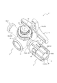
- FIG. 1 is a perspective view showing a medical device 1 as an embodiment of the present disclosure.
- FIG. 2 is an exploded perspective view of the medical device 1.
- the medical device 1 shown in FIGS. 1 and 2 is a three-way stopcock.
- a three-way stopcock as a medical device will be exemplified, but the medical device according to the present disclosure is not limited to the three-way stopcock shown here.
- the medical device according to the present disclosure may be another medical connector different from the three-way stopcock, such as a T-shaped needleless connector.
- the medical device 1 includes a device body 2 and a connecting member 3.
- the instrument main body 2 includes a holder member 11, a cock member 12, and a mixed injection member 13.
- the medical device 1 is made of materials having different flexural modulus and includes two members connected to each other. Although details will be described later, in the medical device 1 of the present embodiment, at least the above-mentioned connecting member 3 and holder member 11 are made of materials having different flexural modulus and are connected to each other.
- the holder member 11 is made of a material having a lower flexural modulus than the connecting member 3.
- the connecting member 3 is made of a material having a flexural modulus higher than that of the holder member 11.
- the "flexural modulus” means a bending characteristic measured by the method specified in JIS K 7171: 2016.
- the connecting member 3 may be referred to as a “hard member” and the holder member 11 may be referred to as a “soft member”.
- FIG. 3 is a top view of the medical device 1.
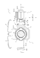
- FIG. 4 is a cross-sectional view of the medical device 1 along the line I-I of FIG.
- FIG. 5 is a cross-sectional view of the medical device 1 along the line II-II of FIG.
- FIG. 6 is a cross-sectional view showing a state in which the instrument main body 2 and the connecting member 3 are separated.
- FIG. 6 shows the same cross-sectional view as that of FIG.
- the holder member 11 as a soft member includes a tubular portion 4.
- the connecting member 3 as a hard member includes a tubular support portion 5 that supports the tubular portion 4 of the holder member 11 as a soft member.
- the tubular support portion 5 includes an inner surface support portion 6 that supports the inner surface of the tubular portion 4 and an outer surface support portion 7 that supports the outer surface of the tubular portion 4.
- an external force that bends one of the holder member 11 as a soft member and the connecting member 3 as a hard member that are connected to each other with respect to the other (hereinafter, simply referred to as "bending external force").
- the tubular portion 4 of the holder member 11 as a soft member is less likely to be deformed. Therefore, it is difficult to disconnect the holder member 11 and the connecting member 3.
- the tubular portion 4 of the holder member 11 as a soft member tries to be deformed by the bending external force, but the tubular support portion 5 of the connecting member 3 as a hard member is formed on the inner surface of the tubular portion 4 and By contacting the outer surface, the deformation of the tubular portion 4 is regulated. As a result, the tubular portion 4 of the holder member 11 as a soft member is less likely to be deformed by the bending external force.
- the above-mentioned "bending external force" in the present embodiment means that one of the holder member 11 and the connecting member 3 is rotated with respect to the other in a plane including the central axis O (see FIG. 4 and the like) of the tubular portion 4. It means such an external force.
- the holder member 11 includes a holder main body 21 and a plurality of port portions 22.
- the plurality of port portions 22 project outward from the holder main body 21.
- the holder body 21 has a substantially cylindrical outer shape. Therefore, the holder body 21 has a substantially cylindrical hollow portion 50 partitioned therein. A cock member 12, which will be described later, is housed in the hollow portion 50.
- the port portion 22 projects from the holder main body 21. The port portion 22 internally partitions a flow path that communicates with the hollow portion 50 of the holder main body 21.
- the plurality of port portions 22 of the present embodiment are composed of a first port portion 22a, a second port portion 22b, and a third port portion 22c. Both are integrally formed with the holder body 21 and extend in the radial direction of the holder body 21.
- the first port portion 22a is a tubular portion that partitions the first flow path 51 that communicates with the hollow portion 50, and is connected to another medical device such as a medical tube 111 (see FIG. 9).
- the second port portion 22b is a tubular portion 4 that partitions the second flow path 52 that communicates with the hollow portion 50, and is, for example, a medical tube 111 (see FIG. 9) or the like via a connecting member 3 described later. Connected to medical equipment.
- the third port portion 22c partitions a third flow path 53 that communicates with the hollow portion 50, and for example, a syringe having a tubular male connector portion at the tip portion or a medical device via a mixed injection member 13 described later. It is connected to other medical devices such as tube 111 (see FIG. 9).
- first other medical device another medical device connected to the first port portion 22a
- second other medical device another medical device connected to the second port portion 22b via the connecting member 3
- third other medical device another medical device connected to the third port portion 22c via the mixed injection member 13
- the first port portion 22a of the present embodiment is a tubular portion integrally molded with the holder main body 21.
- a liquid such as a chemical solution is a holder body 21 from the first other medical device through the first flow path 51 of the first port 22a in a state where the first other medical device is connected to the first port 22a. Flows into the hollow portion 50 of the. Therefore, the first port portion 22a of the present embodiment constitutes a port portion on the upstream side of the flow path of the medical device 1.
- the first port portion 22a of the present embodiment is a female connector portion into which a tubular male connector portion of another medical device is inserted. That is, another medical device is connected to the first port portion 22a by inserting the tubular male connector portion of the other medical device from the tip opening. Further, a male screw portion 22a1 is formed on the outer surface of the first port portion 22a. The male screw portion 22a1 is configured to be screwable with the female screw portion of the lock type male connector portion conforming to ISO80369-7 issued in 2016.
- the second port portion 22b of the present embodiment is a tubular portion 4 integrally molded with the holder main body 21 at a position opposite to the first port portion 22a with the holder main body 21 sandwiched therein.
- the connecting member 3 is connected to the second port portion 22b.
- the second flow path 52 of the second port portion 22b communicates with the flow path 3a partitioned by the connecting member 3.
- a second other medical device is connected to the connecting member 3. Liquids such as chemicals are present in the second flow path 52 and the connecting member from the medical device 1 to the second port 22b in a state where the second other medical device is connected to the second port 22b via the connecting member 3. It flows out to the second other medical device through the flow path 3a of 3. Therefore, the second port portion 22b of the present embodiment and the connecting member 3 described later form a port portion on the downstream side of the flow path of the medical device 1.
- the inner peripheral surface of the tubular portion 4 constituting the second port portion 22b is located on the distal end side and extends to the distal end side with the proximal inner peripheral surface 81 located on the proximal end side.
- the tip inner peripheral surface 82 and an intermediate inner peripheral surface 83 located between the base end inner peripheral surface 81 and the tip inner peripheral surface 82 in the axial direction A are provided.
- the base end inner peripheral surface 81, the tip inner peripheral surface 82, and the intermediate inner peripheral surface 83 each expand from the base end side (right side in FIG. 6) to the tip side (left side in FIG. 6). It is a tapered surface with a diameter.
- the taper angle of the tubular portion 4 constituting the second port portion 22b with respect to the central axis O is the taper angle of the intermediate inner peripheral surface 83 rather than the taper angles of the base end inner peripheral surface 81 and the tip inner peripheral surface 82, respectively. Is larger.
- the taper angle of the intermediate inner peripheral surface 83 is illustrated as “ ⁇ 1”, but the taper angles of the base end inner peripheral surface 81 and the tip inner peripheral surface 82 also mean the angles at the same positions. ..
- the base end inner peripheral surface 81 and the tip inner peripheral surface 82 of the present embodiment are each composed of tapered surfaces, but the present invention is not limited to this configuration, and the inner circumference having a uniform inner diameter in the axial direction A is not limited to this configuration. It may be a surface. Further, in the present embodiment, the taper angle of the base end inner peripheral surface 81 and the taper angle of the tip inner peripheral surface 82 are substantially the same, but may be different.
- the outer peripheral surface of the connecting inner tubular portion 61a of the connecting member 3 described later which is internally fitted in the tubular portion 4 constituting the second port portion 22b, is the base end of the tubular portion 4. It comes into close contact with the inner peripheral surface 81. Details of the tip outer peripheral surface 85 of the outer peripheral surface of the connecting inner tubular portion 61a, which is in close contact with the above-mentioned base end inner peripheral surface 81, will be described later.
- an insertion restricting portion 4b is provided on the inner surface of the tubular portion 4 constituting the second port portion 22b.
- the insertion restricting portion 4b restricts further insertion of the connecting member 3 by abutting the tip surface of the connecting inner tubular portion 61a of the connecting member 3 described later.
- the base end inner peripheral surface 81, the intermediate inner peripheral surface 83, and the tip inner peripheral surface 82 are located closer to the tip end side of the tubular portion 4 than the insertion restricting portion 4b in the axial direction A. ..
- annular groove 4a extending in the circumferential direction C is formed on the outer surface of the tubular portion 4 constituting the second port portion 22b. More specifically, the annular groove 4a of the present embodiment is formed on the outer surface of the tubular portion 4 in the region in the axial direction A in which the tip inner peripheral surface 82 of the tubular portion 4 is formed. As shown in FIG. 4, the claw portion 65 of the connecting member 3 is fitted in the annular groove 4a. Details of the claw portion 65 will be described later.
- the third port portion 22c of the present embodiment is provided at a position different from the position where the first port portion 22a and the second port portion 22b are provided on the peripheral surface of the holder main body 21. More specifically, the third port portion 22c of the present embodiment is located at a position deviated by about 90 degrees from the position where the first port portion 22a and the second port portion 22b are provided in the circumferential direction of the peripheral surface of the holder main body 21. Is integrally molded with the holder body 21.
- the third port portion 22c constitutes a mixed injection port portion.
- the mixed injection port portion is, for example, a port portion used when a liquid such as a chemical solution different from the liquid flowing into the medical device 1 from the first flow path 51 of the first port section 22a flows into the medical device 1. Is.
- a mixed injection member 13 to which a tubular male connector portion of a third other medical device can be connected is attached to the tip portion of the third port portion 22c of the present embodiment.
- the mixed injection member 13 of the present embodiment includes a cap member 41 and an elastic valve body 42. Details of the mixed injection member 13 will be described later.
- Examples of the material of the holder member 11 include polyolefins such as polyethylene, polypropylene, and ethylene-propylene copolymer; ethylene-vinyl acetate copolymer (EVA); polyvinyl chloride; polyvinylidene chloride; polystyrene; polyamide; polyimide; polyamide.
- polyolefins such as polyethylene, polypropylene, and ethylene-propylene copolymer
- EVA ethylene-vinyl acetate copolymer
- polyvinyl chloride polyvinylidene chloride
- polystyrene polyamide
- polyimide polyimide
- Iimide Polycarbonate; Poly- (4-methylpentene-1); Ionomer; Acrylic resin; Polymethylmethacrylate; Acrylonitrile-butadiene-styrene copolymer (ABS resin); Acrylonitrile-styrene copolymer (AS resin); butadiene- Styrene copolymer; polyesters such as polyethylene terephthalate (PET), polybutylene terephthalate (PBT), polycyclohexane terephthalate (PCT); polyether; polyetherketone (PEK); polyetheretherketone (PEEK); polyetherimide; Polyacetal (POM); polyphenylene oxide; modified polyphenylene oxide; polysulfone; polyethersulfone; polyphenylene sulfide; polyallylate; aromatic polyester (liquid crystal polymer); polytetrafluoroethylene, polyvinylidene fluoride, and other fluororesins; Resin material can be mentioned.
- PET polyethylene
- the cock member 12 housed in the hollow portion 50 in which the holder body 21 is partitioned will be described.
- the cock member 12 can rotate around the central axis of the holder body 21 while being housed in the hollow portion 50 of the holder body 21.
- the cock member 12 rotates with respect to the holder member 11 while sliding with the inner surface of the holder body 21 that partitions the hollow portion 50.
- the plurality of port portions 22 in this embodiment, the first port portion 22a, the second port portion 22b, and the third port portion 22c) are divided into compartments.
- connection state between the flow paths changes.
- the connection state between the flow paths is changed by switching the open / closed state of each flow path by the rotating cock member 12. That is, the connection state between the flow paths is switched between a closed state in which each flow path is closed by the cock member 12 and an open state in which each flow path is not closed by the cock member 12 by the rotation of the cock member 12. ,Change.
- the cock member 12 of the present embodiment is provided at one end of the cock main body 31 housed in the holder main body 21 of the holder member 11 and the cock main body 31, and the holder member 11 A handle portion 32 located outside is provided.
- the cock body 31 can rotate around the central axis of the holder body 21 while being housed in the hollow portion 50 of the holder body 21.
- the cock main body 31 is a flow path (first flow path 51 in this embodiment) of a plurality of port portions 22 (first port portion 22a, second port portion 22b, and third port portion 22c in the present embodiment) of the holder member 11.
- the connection flow path 54 connecting between the second flow path 52 and the third flow path 53) is partitioned.
- the cock main body 31 of the present embodiment has a substantially cylindrical outer shape housed in the hollow portion 50 of the holder main body 21.
- the outer diameter of the cock main body 31 is substantially equal to the inner diameter of the inner surface of the holder main body 21 that partitions the hollow portion 50. Therefore, the cock main body 31 of the present embodiment rotates with respect to the holder member 11 while sliding with the inner surface of the holder main body 21 in a state of being housed in the hollow portion 50.
- the handle portion 32 is a portion that is gripped and operated by the user.
- the handle portion 32 is integrally formed with the cock main body 31. Therefore, by rotating the handle portion 32 around the central axis of the holder main body 21, the cock main body 31 located in the hollow portion 50 can be rotated around the central axis of the holder main body 21.
- the mixed injection member 13 is attached to the tip of the third port portion 22c of the holder member 11.
- the mixed injection member 13 of the present embodiment has a cap member 41 for partitioning an insertion opening 41a into which a tubular male connector portion of a third other medical device can be inserted, and a slit 42a, and closes the insertion opening 41a.
- An elastic valve body 42 is provided. The male connector portion of the third other medical device is inserted into the medical device 1 through the insertion opening 41a through the slit 42a of the elastic valve body 42. In this way, a third other medical device can be connected to the third port portion 22c of the holder member 11 via the mixed injection member 13.
- the mixed injection member 13 of the present embodiment is a female connector portion into which the tubular male connector portion of the third other medical device is inserted. That is, another medical device is connected to the mixed injection member 13 by inserting the tubular male connector portion of the other medical device from the insertion opening 41a. Further, a male screw portion 41b is formed on the outer surface of the cap member 41 of the mixed injection member 13. The male screw portion 41b is configured to be screwable with the female screw portion of the lock type male connector portion conforming to ISO80369-7 issued in 2016.
- Examples of the material of the cap member 41 include the same materials as various materials that can be used as the material of the holder member 11 described above.
- the material constituting the cap member 41 may be the same as or different from the material constituting the holder member 11.
- the elastic valve body 42 is molded and elastically deformable.
- Examples of the material of the elastic valve body 42 include natural rubber, isoprene rubber, butadiene rubber, styrene-butadiene rubber, nitrile rubber, chloroprene rubber, butyl rubber, acrylic rubber, ethylene-propylene rubber, hydrin rubber, urethane rubber, and silicone rubber.
- Various rubber materials such as fluororubber, and various heats such as styrene-based, polyolefin-based, polyvinyl chloride-based, polyurethane-based, polyester-based, polyamide-based, polybutadiene-based, transpolyisoprene-based, fluororubber-based, and chlorinated polyethylene-based Examples thereof include plastic rubber, and one or a mixture of two or more of these may be used.
- the cap member 41 in the mixed injection member 13 of the present embodiment sandwiches the circular flat elastic valve body 42 from the top surface (the surface exposed to the outside) and the bottom surface which is the surface opposite to the top surface. It is composed of a top surface cap 43 and a bottom surface cap 44 to be compressed, but the configuration is not limited to this.
- the cap member may have, for example, an integral configuration of the third port portion and the bottom surface cap, that is, a configuration in which the elastic valve body is sandwiched and compressed between the third port portion of the holder member and the top surface cap.
- the connecting member 3 is made of a single material. As shown in FIG. 4, the connecting member 3 includes a substantially cylindrical inner tubular portion 61 for partitioning the flow path 3a, and an annular flange portion 62 protruding outward in the radial direction B from the outer surface of the inner tubular portion 61. A substantially cylindrical outer tubular portion 63 that protrudes from the annular flange portion 62 in the axial direction A.
- the inner tubular portion 61 projects from the annular flange portion 62 toward one end side in the axial direction A (on the right side in FIG. 4), and is inserted into the tubular portion 4 constituting the second port portion 22b of the holder member 11 described above. It includes a connecting inner tubular portion 61a and a tip inner tubular portion 61b protruding from the annular flange portion 62 to the other end side (left side in FIG. 4) in the axial direction A.
- the outer peripheral surface of the connecting inner tubular portion 61a of the inner tubular portion 61 is a base end outer peripheral surface 84 continuous with the annular flange portion 62 and a tip end extending to the tip end side.
- the outer peripheral surface 85 is provided.
- each of the base end outer peripheral surface 84 and the tip end outer peripheral surface 85 is a tapered surface whose diameter is reduced from the base end side to the tip end side (from the left side to the right side in FIG. 4).
- the base end outer peripheral surface 84 and the tip outer peripheral surface 85 of the present embodiment are each composed of tapered surfaces, but the present invention is not limited to this configuration, and as an inner peripheral surface having a uniform inner diameter in the axial direction A. May be good. Further, each of the base end outer peripheral surface 84 and the tip end outer peripheral surface 85 may have a uniform taper angle regardless of the position in the axial direction A. In this case, the taper angles of the base end outer peripheral surface 84 and the tip end outer peripheral surface 85 may be substantially the same angle or different angles. In the present embodiment, the taper angle of the base end outer peripheral surface 84 and the taper angle of the tip root portion surface 85a of the tip outer peripheral surface 85, which will be described later, are different, but they may be substantially equal.
- the tip outer peripheral surface 85 of the present embodiment is composed of two tapered surfaces having different taper angles.
- the tip outer peripheral surface 85 of the present embodiment has a tip root surface 85a continuous with the proximal outer peripheral surface 84 and a tip surface having a larger taper angle than the tip root surface 85a and extending to the tip. It is composed of 85b and.
- the tip outer peripheral surface 85 may be formed of one cylindrical surface or a tapered surface, but it is preferably formed of a plurality of outer peripheral surfaces having different taper angles as in the present embodiment.
- the inner peripheral surface of the tubular portion 4 constituting the second port portion 22b of the holder member 11 which is externally fitted to the connecting inner tubular portion 61a is the tip of the connecting inner tubular portion 61a. It comes into close contact with the outer peripheral surface 85. More specifically, the tip outer peripheral surface 85 of the connecting inner tubular portion 61a is in close contact with the base end inner peripheral surface 81 of the tubular portion 4 of the holder member 11.
- the connecting inner tubular portion 61a of the connecting member 3 is inserted into the tubular portion 4 of the holder member 11, and the tubular portion 4 and the connecting inner tubular portion 61a overlap in the radial direction B.
- An insertion region T1 is formed (see FIG. 4).
- the contact region T2 in which the inner peripheral surface of the tubular portion 4 and the outer peripheral surface of the connecting inner tubular portion 61a are in close contact is only a part of the above-mentioned insertion region T1.
- the holder member 11 and the connecting member 3 rotate relatively around the central axis O of the tubular portion 4 as compared with the configuration in which the contact region T2 is the entire insertion region T1.
- the sliding resistance can be reduced.
- the taper angle of the tip root portion surface 85a with respect to the axial direction A is smaller than the taper angle of the intermediate inner peripheral surface 83 with respect to the axial direction A (see “ ⁇ 1” in FIG. 6). By doing so, it is easy to realize a configuration in which the tip root portion surface 85a does not abut on the intermediate inner peripheral surface 83 but abuts on the base end inner peripheral surface 81. Further, the taper angle of the tip root portion surface 85a with respect to the axial direction A is larger than the taper angle of the proximal end inner peripheral surface 81 with respect to the axial direction A.
- the contact region T2 of the present embodiment is formed over the entire circumferential direction C of the tubular portion 4 and the connecting inner tubular portion 61. That is, the base end inner peripheral surface 81 (see FIG. 6) of the inner peripheral surface of the tubular portion 4 is the tip outer peripheral surface 85 (see FIG. 6) of the outer peripheral surface of the connecting inner tubular portion 61a, and the circumferential direction C. It is in contact with the whole area of. As a result, the hollow portion of the tubular portion 4 and the flow path 3a as the hollow portion partitioned by the connecting member 3 are liquid-tightly connected.
- the outer surface of the connecting inner tubular portion 61 of the connecting member 3 and the inner surface of the tubular portion 4 of the holder member 11 may be brought into contact with each other to ensure the sealing property of the connecting portion. Sealability may be ensured by interposing another member such as an O-ring between the outer surface of the connecting inner tubular portion 61a and the inner surface of the tubular portion 4.
- the tip inner tubular portion 61b of the inner tubular portion 61 is, for example, a tubular male connector portion conforming to ISO80369-7 issued in 2016.
- the connecting member 3 includes a male connector portion that partitions the flow path 3a inside and is inserted into the female connector portion of the second other medical device.
- the outer tubular portion 63 includes a substantially cylindrical connecting outer tubular portion 63a and a substantially cylindrical tip outer tubular portion 63b.
- the connecting outer tubular portion 63a protrudes from the outer edge portion of the annular flange portion 62 toward one end side (right side in FIG. 4) in the axial direction A, and is outside the radial direction B of the connecting inner tubular portion 61a of the inner tubular portion 61.
- the tip outer tubular portion 63b protrudes from the outer edge portion of the annular flange portion 62 to the other end side (left side in FIG. 4) in the axial direction A, and the tip inner tubular portion 61b of the inner tubular portion 61 is outside the radial direction B.
- the connecting outer tubular portion 63a of the outer tubular portion 63 is continuous with the peripheral wall portion 64 and only a part of the peripheral wall portion 64, and the radial direction B is other than the continuous position. It is provided with a claw portion 65 that can be elastically deformed.
- the connecting outer tubular portion 63a covers the outer peripheral surface of the tubular portion 4 of the holder member 11.
- the claw portion 65 of the present embodiment only one side of the axial direction A (right side in FIG. 4) is continuous with the peripheral wall portion 64, and the other side of the axial direction A and both sides of the circumferential direction C are peripheral wall portions. It is not continuous with 64. Therefore, the claw portion 65 of the present embodiment is elastically deformed and swingable in the radial direction B with a position continuous with the peripheral wall portion 64 on one side of the axial direction A as a fulcrum. Further, as shown in FIG. 1, a plurality of (four in the present embodiment) claw portions 65 of the present embodiment are provided at different positions in the circumferential direction C.
- the claw portion 65 of the present embodiment includes a deformed portion 65a that elastically deforms in the radial direction B, and a locking protrusion 65b that protrudes inward in the radial direction B from the tip portion of the deformed portion 65a. It has.
- an annular groove 4a (see FIG. 4 and the like) extending in the circumferential direction C is formed on the outer surface of the tubular portion 4 constituting the second port portion 22b of the holder member 11.
- the claw portion 65 of the present embodiment is located outside the tubular portion 4 of the holder member 11 in the radial direction B. Then, as shown in FIG. 4, the locking protrusion 65b of the claw portion 65 is fitted into the annular groove 4a, so that the holder member 11 and the connecting member 3 are connected so as not to be separated in the axial direction A.
- the claw portion 65 is elastically deformable in the radial direction B as described above. With such a configuration, it is possible to suppress an increase in sliding resistance when the tubular portion 4 and the connecting inner tubular portion 61a rotate relative to the central axis O.
- a female screw portion 63b1 that can be screwed with a lock-type female connector portion conforming to ISO80369-7 issued in 2016 is formed on the inner surface of the tip outer tubular portion 63b of the outer tubular portion 63. Has been done.
- the connecting member 3 of the present embodiment constitutes a lock-type male connector portion conforming to ISO80369-7 issued in 2016 by the tip inner tubular portion 61b and the tip outer tubular portion 63b. Therefore, the tip inner tubular portion 61b and the tip outer tubular portion 63b of the connection member 3 of the present embodiment can be liquid-tightly connected to the lock type female connector portion conforming to ISO80369-7 issued in 2016 by screwing. Is.
- the tip inner tubular portion 61b of the connecting member 3 of the present embodiment is a tubular male connector portion conforming to ISO80369-7 issued in 2016.
- the tip outer tubular portion 63b of the connection member 3 of the present embodiment is located outside the radial direction B of the tip inner tubular portion 61b as a male connector portion, and can be locked with a second other medical device. It is a locking part.
- the tip outer tubular portion 63b as the locking portion is screw-joined to the female connector portion conforming to ISO80369-7 issued in 2016 provided in the second other medical device by the female screw portion 63b1 on the inner surface thereof. This locks it into a second other medical device.
- Examples of the material of the connecting member 3 of the present embodiment include the same material as the material that can be used as the holder member 11 of the instrument body 2 described above. However, the connecting member 3 is made of a material having a flexural modulus higher than that of the holder member 11.
- the medical device 1 is composed of materials having different flexural modulus and includes two members connected to each other.
- the holder member 11 and the connecting member 3 are made of materials having different flexural modulus.
- the holder member 11 is made of polypropylene, for example, and the connecting member 3 is made of polycarbonate, for example.
- the connecting member 3 is a hard member made of a material that is not easily deformed with respect to the holder member 11.
- the holder member 11 is a soft member made of a material that is easily deformed with respect to the connecting member 3.
- the connecting member 3 as a hard member is connected to the holder member 11 as a soft member.
- the tubular portion 4 and the connecting member 3 of the holder member 11 are restricted from moving in a direction in which they are separated from each other along the axial direction A (hereinafter, simply referred to as "separation direction"). .. Therefore, even if one of the holder member 11 and the connecting member 3 is moved with respect to the other in the separation direction, the two cannot be separated. That is, the tubular portion 4 and the connecting member 3 of the holder member 11 are configured so as not to separate with respect to movement in the separation direction. In other words, when focusing on an arbitrary predetermined portion of the holder member 11 and an arbitrary predetermined portion of the connecting member 3, the distance between these two predetermined portions in the axial direction A does not exceed a predetermined distance. ing.
- the holder member 11 and the connecting member 3 are arranged so as to overlap each other in the axial direction A, and the portion where the holder member 11 and the connecting member 3 come into contact with each other and interfere with each other when they try to separate from each other in the axial direction A It can be realized by providing it in.
- the tubular portion 4 of the holder member 11 includes a wall surface 8a that abuts and regulates the movement of the connecting member 3 in the separation direction.
- the connecting member 3 includes a wall surface 8b that abuts on the wall surface 8a to restrict the movement of the tubular portion 4 in the separation direction.
- annular groove 4a is partitioned on the outer surface of the tubular portion 4.
- the connecting member 3 is connected to the tubular portion 4 by fitting the locking protrusion 65b of the claw portion 65 in the connecting outer tubular portion 63a of the connecting member 3 into the annular groove 4a of the tubular portion 4. That is, the locking protrusion 65b and the annular groove 4a interfere with each other in the axial direction A and come into contact with each other, so that the connecting member 3 and the holder member 11 are not separated in the axial direction A.
- the above-mentioned wall surface 8a of the tubular portion 4 is formed by the groove wall of the annular groove 4a.
- the above-mentioned wall surface 8b of the connecting member 3 is composed of an end surface on the tip end side of the locking protrusion 65b of the claw portion 65.
- the tubular portion 4 and the connecting member 3 of the holder member 11 move in a direction opposite to the direction in which they are separated from each other along the axial direction A (hereinafter, simply referred to as "approaching direction").
- approximately direction the direction in which they are separated from each other along the axial direction A
- the tubular portion 4 of the holder member 11 includes a wall surface 9a that abuts and regulates the movement of the connecting member 3 in the approaching direction.
- the connecting member 3 includes a wall surface 9b that abuts on the wall surface 9a to restrict the movement of the tubular portion 4 in the approaching direction.
- the tip surface of the tubular portion 4 of the holder member 11 and the connecting member 3 Is in contact with one side surface.
- the relative movement of the tubular portion 4 and the connecting member 3 of the holder member 11 in the approaching direction is restricted.
- the above-mentioned wall surface 9a of the tubular portion 4 is formed by the tip surface of the tubular portion 4.
- the above-mentioned wall surface 9b of the connecting member 3 is composed of one surface of the annular flange portion 62.
- tubular portion 4 and the connecting member 3 of the holder member 11 of the present embodiment are restricted from moving relative to each other in the separating direction and the approaching direction.
- tubular portion 4 of the holder member 11 as a soft member is supported by the tubular support portion 5 of the connecting member 3 as a hard member.
- the tubular support portion 5 supports the connecting inner tubular portion 61a as the inner surface support portion 6 that supports the inner surface of the tubular portion 4 and the outer surface of the tubular portion 4. It is composed of a connecting outer tubular portion 63a as an outer surface supporting portion 7 to be formed.
- the connecting inner tubular portion 61a as the inner surface support portion 6 is inserted into the inside through the tip opening of the tubular portion 4.
- the outer surface of the connecting inner tubular portion 61a as the inner surface support portion 6 abuts on the inner surface of the tubular portion 4 to bring the inner surface of the tubular portion 4 from the inside in the radial direction. It supports toward the outside.
- the inner surface of the connecting outer tubular portion 63a as the outer surface support portion 7 abuts on the outer surface of the tubular portion 4, so that the outer surface of the tubular portion 4 is brought into radial direction B. It supports from the outside to the inside of.
- the tubular portion 4 of the holder member 11 of the present embodiment has a connecting inner tubular portion 61a as the inner surface supporting portion 6 of the connecting member 3 and a connecting outer tubular portion as the outer surface supporting portion 7 of the connecting member 3. It is sandwiched from both the inner and outer sides of the radial direction B by 63a, and is sandwiched from both the inner and outer sides of the radial direction B. More specifically, the tubular portion 4 of the present embodiment includes a connecting inner tubular portion 61a as the inner surface supporting portion 6 of the connecting member 3 and a connecting outer tubular portion 63a as the outer surface supporting portion 7 of the connecting member 3. , Is sandwiched and compressed from both the inner and outer sides of the radial direction B.
- the holder member 11 and the connecting member 3 of the present embodiment are fitted with the annular groove 4a and the claw portion 65, and the connecting inner tubular portion 61a and the connecting outer tubular portion 63a in the radial direction of the connecting member 3. B It is connected by sandwiching the tubular portion 4 from both the inner and outer sides.
- the diameter of the tubular portion 4 of the holder member 11 is formed by the connecting inner tubular portion 61a as the inner surface supporting portion 6 of the connecting member 3 and the connecting outer tubular portion 63a as the outer surface supporting portion 7 of the connecting member 3.
- the tubular portion 4 is in contact with the connecting inner tubular portion 61a, so that the deformation of the tubular portion 4 inward in the radial direction B is restricted. Further, the tubular portion 4 is in contact with the connecting outer tubular portion 63a, so that the deformation of the tubular portion 4 outward in the radial direction B is restricted. Therefore, the tubular portion 4 of the holder member 11 as a soft member is less likely to be deformed by the bending external force, and as a result, the tubular portion 4 is deformed and the connection state with the connecting member 3 is released. Can be suppressed.
- the inner surface support portion 6 of the present embodiment is composed of the connecting inner tubular portion 61a, but is not limited to this configuration.
- the inner surface support portion 6 is not limited to a tubular configuration extending over the entire circumferential direction C, and for example, the inner surface support portion 6 is composed of a plurality of portions intermittently arranged at intervals in the circumferential direction C. It may be 6. The distance between two parts adjacent to the circumferential direction C, the circumferential length of each part, the shape of each part, and the like can be appropriately designed.
- the inner surface support portion 6 may be formed of, for example, a tubular portion having one or more openings formed in the peripheral wall. The position, shape, etc. of the opening can be appropriately designed. Details of one modification of the inner surface support portion 6 will be described later (see FIG. 8).
- the outer surface support portion 7 of the present embodiment is composed of the connecting outer tubular portion 63a, but is not limited to this configuration.
- the outer surface support portion 7 is not limited to a tubular configuration extending over the entire circumferential direction C, and for example, the outer surface support portion 7 is composed of a plurality of portions intermittently arranged at intervals in the circumferential direction C. It may be 7.
- the distance between two parts adjacent to the circumferential direction C, the circumferential length of each part, the shape of each part, and the like can be appropriately designed.
- the outer surface support portion 7 may be formed of, for example, a tubular portion having one or more openings formed in the peripheral wall. The position, shape, etc. of the opening can be appropriately designed. Details of one modification of the outer surface support portion 7 will be described later (see FIG. 8).
- the inner surface support portion 6 and the outer surface support portion 7 are not limited to the configuration of the tubular portion.
- the inner surface support portion 6 is preferably composed of an inner tubular portion (in this embodiment, a connected inner tubular portion 61a) inserted into the tubular portion 4. By doing so, it is possible to prevent the ease of deformation of the tubular portion 4 inward in the radial direction B from varying depending on the position in the circumferential direction C.
- the outer surface support portion 7 is preferably composed of an outer tubular portion (in this embodiment, a connected outer tubular portion 63a) that surrounds the outer side of the tubular portion 4 in the radial direction B. By doing so, it is possible to prevent the ease of deformation of the tubular portion 4 outward in the radial direction B from varying depending on the position in the circumferential direction C.
- annular groove 4a and the locking protrusion 65b of the present embodiment are located in the region of the axial direction A in which the inner surface support portion 6 and the outer surface support portion 7 face each other in the radial direction B.
- the locking protrusion 65b is less likely to come off from the annular groove 4a. Therefore, it is possible to further prevent the connection state of the instrument main body 2 and the connecting member 3 from being unintentionally released.
- the holder member 11 is provided with an annular groove 4a as a concave portion
- the connecting member 3 is provided with a locking protrusion 65b as a convex portion that fits into the annular groove 4a, but the configuration is limited to this. I can't. That is, the holder member 11 may have a convex portion such as a locking protrusion, and the connecting member 3 may be provided with a concave portion such as an annular groove 4a into which the convex portion fits.
- the connecting member 3 of the present embodiment is rotatably connected to the tubular portion 4 constituting the second port portion 22b of the holder member 11. Specifically, the connecting member 3 and the holder member 11 are relatively rotatable around the central axis O of the tubular portion 4.
- the connecting outer tubular portion 63a of the connecting member 3 of the present embodiment includes a plurality of claw portions 65 arranged at different positions in the circumferential direction C.
- the locking protrusions 65b of the plurality of claws 65 are fitted into the annular groove 4a of the tubular portion 4. Therefore, the locking protrusion 65b of the claw portion 65 moves in the annular groove 4a in the circumferential direction C, so that the connecting member 3 is at the center of the tubular portion 4 while maintaining the connected state with the tubular portion 4. It can rotate around the axis O.
- the medical device 1 is a plurality of infusion lines.
- twisting of the infusion line is unlikely to occur, and even if twisting occurs, it is easy to eliminate it.
- an infusion line including a three-way stopcock which is the medical device 1 of the present embodiment, is formed, an upstream portion of the infusion line connected to the first port portion 22a of the holder member 11 and a connecting member 3 It becomes rotatable between the downstream portion of the infusion line connected to the tip inner tubular portion 61b as the male connector portion of the above.
- the holder member 11 and the connecting member 3 rotate relatively, twisting is unlikely to occur between the upstream side portion and the downstream side portion of the infusion line sandwiching the medical device 1. Further, even if a twist occurs between the upstream side portion and the downstream side portion of the infusion line sandwiching the medical device 1, the holder member 11 and the connecting member 3 rotate relative to each other. The twist can be eliminated.
- the hollow portion of the tip outer tubular portion 63b as the tubular male connector portion in the connecting member 3 as the hard member of the present embodiment is a holder as the soft member of the present embodiment. It communicates with the hollow portion of the tubular portion 4 of the member 11. More specifically, in the present embodiment, in a state where the tubular portion 4 of the holder member 11 and the connecting member 3 are connected, the flow path 3a of the connecting member 3 is the first of the tubular portion 4 of the holder member 11. It communicates with the two flow paths 52 in a liquid-tight manner. That is, the holder member 11 and the connecting member 3 of the present embodiment are relatively rotatable and connected so that the internal flow path becomes liquid-tight.
- the liquidtightness of this flow path is such that, for example, the outer surface of the connecting inner tubular portion 61 of the connecting member 3 and the inner surface of the tubular portion 4 of the holder member 11 are brought into close contact with each other. Is feasible.
- the medical device 1 of the present embodiment includes a lock-type female connector portion conforming to ISO80369-7 issued in 2016 and a lock-type male connector portion conforming to ISO80369-7 issued in 2016.
- the tubular portion constituting the first port portion 22a is a lock-type female connector portion having a male screw portion 22a1 on the outer surface and conforming to ISO80369-7 issued in 2016.
- the mixed injection member 13 attached to the third port portion 22c is a lock type female connector portion conforming to ISO80369-7 issued in 2016, which is provided with a male screw portion 41b on the outer surface.
- the tip inner tubular portion 61b and the tip outer tubular portion 63b of the connecting member 3 connected to the second port portion 22b constitute a lock type male connector portion conforming to ISO80369-7 issued in 2016. There is.
- FIG. 7 is a cross-sectional view showing a state in which two medical instruments 1 are connected to each other by using the first port portion 22a of the holder member 11 and the connecting member 3.
- Each medical device 1 shown in FIG. 7 shows a cross section in the same cross-sectional view as that in FIG.
- first medical device 1a the medical device 1 on the left side
- second medical device 1b the medical device 1 on the right side
- the left side is the downstream side of the flow path
- the right side is the upstream side of the flow path.
- the first port portion 22a of the first medical device 1a is connected to the tip inner tubular portion 61b and the tip outer tubular portion 63b constituting the lock type male connector portion of the connecting member 3 of the second medical device 1b. Therefore, specifically, the male threaded portion 22a1 of the first port portion 22a of the first medical device 1a is screwed with the female threaded portion 63b1 of the connecting member 3 of the second medical device 1b. That is, the first medical device 1a and the second medical device 1b are connected by a screw joint.
- the holder member 11 of the first medical device 1a and the holder member 11 of the second medical device 1b are connected via the connecting member 3 of the second medical device 1b.
- the second medical device 1b of the present embodiment includes the holder member 11 and the connecting member 3 as two members that are rotatably connected. Further, the connecting member 3 of the second medical device 1b can be screw-joined to the holder member 11 of the first medical device 1a having the same shape as the second medical device 1b. With such a configuration, a plurality of medical devices 1 can be connected in series by screw joining. Further, even if an external force in the direction of loosening the screw joint with the connecting member 3 of the second medical device 1b acts on the holder member 11 of the first medical device 1a, the torque is still applied to the holder of the second medical device 1b. It is easy to use for rotating the member 11 and the connecting member 3.
- the screw joint between the holder member 11 of the first medical device 1a and the connecting member 3 of the second medical device 1b is hard to loosen. That is, in a state where a plurality of medical devices 1 are connected by screw joining, it is possible to prevent the screw joint from loosening or being released due to an unintended external force acting on the holder member 11.
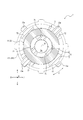
- FIG. 8 shows a cross-sectional view of the same cross section as that of FIG.
- the cylinder support portion 5 includes an inner surface support portion 6 and an outer surface support portion 7.
- the inner surface support portion 6 shown in FIG. 8 is composed of a plurality of curved plate portions 71 arranged at intervals in the circumferential direction C. Three curved plate portions 71 shown in FIG. 8 are arranged at intervals in the circumferential direction C.
- the outer surface support portion 7 shown in FIG. 8 is composed of a plurality of curved plate portions 72 arranged at intervals in the circumferential direction C.
- Four curved plate portions 72 shown in FIG. 8 are arranged at intervals in the circumferential direction C.
- the inner surface support portion 6 and the outer surface support portion 7 of the tubular support portion 5 do not have to be tubular portions.
- the number, shape, and circumferential length of the curved plate portions 71 constituting the inner surface support portion 6 are not particularly limited. However, in an arbitrary cross section of the tubular portion 4 orthogonal to the axial direction A, the sum of the circumferential lengths of the convex curved surfaces abutting on the inner surfaces of the tubular portions 4 of all the curved plate portions 71 is the tubular portion. It is preferably 1/3 or more (120 ° or more at the central angle) of the inner peripheral length of 4 and more preferably 2/3 or more (240 ° or more at the central angle).
- the convex curved surfaces abutting on the inner surface of the tubular portion 4 of the curved plate portion 71 are dispersedly arranged over the entire circumferential direction C at a predetermined interval.
- the inner surface of the tubular portion 4 is supported by the curved plate portion 71 as the inner surface support portion 6 over the entire circumferential direction C. Therefore, it is possible to prevent the ease of deformation of the tubular portion 4 inward in the radial direction B from varying depending on the position in the circumferential direction C.
- the number, shape, and circumferential length of the curved plate portions 72 constituting the outer surface support portion 7 are not particularly limited. However, in an arbitrary cross section of the tubular portion 4 orthogonal to the axial direction A, the sum of the circumferential lengths of the concave curved surfaces in contact with the outer surfaces of the tubular portions 4 of all the curved plate portions 72 is the tubular portion 4. It is preferably 1/3 or more (120 ° or more at the center angle), and more preferably 2/3 or more (240 ° or more at the center angle).
- the concave curved surface that abuts on the outer surface of the tubular portion 4 of the curved plate portion 72 is preferably arranged so as to be dispersed over the entire circumferential direction C at a predetermined interval.
- the outer surface of the tubular portion 4 is supported by the curved plate portion 72 as the outer surface support portion 7 over the entire circumferential direction C. Therefore, it is possible to prevent the tubular portion 4 from being easily deformed outward in the radial direction B from varying depending on the position in the circumferential direction C.
- each of the curved plate portions 71 constituting the inner surface support portion 6 has a radial direction B in at least one of the curved plate portions 72 forming the outer surface support portion 7 and at least a part in the circumferential direction C. overlapping.
- each curved plate portion 71 constituting the inner surface support portion 6 overlaps the curved plate portion 72 forming the outer surface support portion 7 in the radial direction B.
- the curved plate portion 72 constituting the outer surface support portion 7 completely covers the outer side of each of the curved plate portions 71 forming the inner surface support portion 6 in the radial direction B.
- the curved plate portion 72 as the outer surface support portion 7 shown in FIG. 8 includes a rib 72a protruding outward in the radial direction B.
- the strength of the curved plate portion 72 can be increased, and the deformation of the tubular portion 4 to the outside in the radial direction B can be further suppressed.
- FIG. 9 is a diagram showing an infusion set 100.
- the infusion set 100 shown in FIG. 9 includes a three-way stopcock as the medical device 1 shown in FIGS. 1 to 7, but may be configured to include a medical connector having a different shape as the medical device according to the present disclosure. Further, the infusion set may include a medical device including the cylinder support portion 5 shown in FIG.
- the infusion set 100 forms an infusion line connecting an infusion bag (not shown in FIG. 9) to an indwelling needle (not shown in FIG. 9).
- the infusion set 100 includes a plurality of medical tubes 111, a drip tube 112 in which the flow rate of the infusion solution supplied from the infusion bag can be visually recognized, and an adjustment for adjusting the flow rate of the infusion solution in the medical tube 111. It includes a clamp 113, an air vent filter 114 that discharges (or supplies) air existing in the infusion line, and a one-touch clamp 115 that closes the medical tube 111.
- a three-way stopcock as a medical device 1 is provided between the adjustment clamp 113 and the air vent filter 114.
- the three-way stopcock as the medical device 1 connects between the first medical tube 111a extending downstream from the drip tube 112 and the second medical tube 111b extending upstream of the air vent filter 114. It forms part of the main line of the infusion line. More specifically, the first port portion 22a of the three-way stopcock as the medical device 1 is connected to the first medical tube 111a as the other first medical device.
- a lock-type male connector portion conforming to ISO80369-7 issued in 2016 is provided at the tip of the first medical tube 111a.
- the connecting member 3 connected to the second port portion 22b of the three-way stopcock as the medical device 1 is connected to the second medical tube 111b as another second medical device.
- a lock-type female connector portion conforming to ISO80369-7 issued in 2016 is provided at the base end portion of the second medical tube 111b.
- a third medical tube 111c as another third medical device is connected to the third port portion 22c of the three-way stopcock as the medical device 1 via a mixed injection member 13 (see FIG. 1). ..
- a lock-type male connector portion conforming to ISO80369-7 issued in 2016 is provided at the tip of the third medical tube 111c.
- the third medical tube 111c connected to the third port portion 22c via the mixed injection member 13 (see FIG. 1) constitutes a sub-line of the infusion line. Therefore, inside the three-way stopcock as the medical device 1, the main line and the sub line of the infusion line are connected.
- the three-way stopcock as the medical device 1 is provided between the adjusting clamp 113 and the air vent filter 114, but the position of the medical device 1 is not limited to this position and can be provided at a desired position. ..
- the infusion set 100 shown in FIG. 9 has a configuration in which only one three-way stopcock as the medical device 1 is provided, but as shown in FIG. 7, a plurality of three-way stopcocks as the medical device 1 are continuously connected. It may be a configuration.
- the medical device according to the present disclosure is not limited to the specific configuration specified in the above-described embodiment and modification, and can be variously modified or modified without departing from the gist of the invention described in the claims. Is. Specifically, the medical device 1 described above is a three-way stopcock, but may be another medical device such as a medical connector having another shape. Therefore, the two members made of materials having different flexural modulus and connected to each other are not limited to the holder member 11 and the connecting member 3 described above, and may be appropriately determined according to the specific configuration of the medical device. Good.
- This disclosure relates to medical devices.
Landscapes
- Health & Medical Sciences (AREA)
- Heart & Thoracic Surgery (AREA)
- Pulmonology (AREA)
- Engineering & Computer Science (AREA)
- Anesthesiology (AREA)
- Biomedical Technology (AREA)
- Hematology (AREA)
- Life Sciences & Earth Sciences (AREA)
- Animal Behavior & Ethology (AREA)
- General Health & Medical Sciences (AREA)
- Public Health (AREA)
- Veterinary Medicine (AREA)
- Infusion, Injection, And Reservoir Apparatuses (AREA)
Abstract
L'instrument médical selon la présente invention comprend deux éléments respectivement composés de matériaux ayant des modules de flexion différents et reliés l'un à l'autre, parmi les deux éléments, l'élément souple composé du matériau ayant un module de flexion faible comprend une partie cylindrique, tandis que, des deux éléments, l'élément dur composé du matériau ayant un module de flexion élevé comprend une partie de support de cylindre pour supporter la partie cylindrique, la partie de support de cylindre ayant une partie de support de surface interne pour supporter une surface interne de la partie cylindrique et une partie de support externe pour supporter une surface externe de la partie cylindrique.
Priority Applications (4)
| Application Number | Priority Date | Filing Date | Title |
|---|---|---|---|
| CN202080006643.0A CN113164730A (zh) | 2019-03-08 | 2020-02-03 | 医疗器械 |
| JP2021505585A JPWO2020183978A1 (fr) | 2019-03-08 | 2020-02-03 | |
| EP20771129.2A EP3919113A4 (fr) | 2019-03-08 | 2020-02-03 | Instrument médical |
| US17/468,556 US20210402168A1 (en) | 2019-03-08 | 2021-09-07 | Medical device |
Applications Claiming Priority (2)
| Application Number | Priority Date | Filing Date | Title |
|---|---|---|---|
| JP2019-042171 | 2019-03-08 | ||
| JP2019042171 | 2019-03-08 |
Related Child Applications (1)
| Application Number | Title | Priority Date | Filing Date |
|---|---|---|---|
| US17/468,556 Continuation US20210402168A1 (en) | 2019-03-08 | 2021-09-07 | Medical device |
Publications (1)
| Publication Number | Publication Date |
|---|---|
| WO2020183978A1 true WO2020183978A1 (fr) | 2020-09-17 |
Family
ID=72426193
Family Applications (1)
| Application Number | Title | Priority Date | Filing Date |
|---|---|---|---|
| PCT/JP2020/003978 WO2020183978A1 (fr) | 2019-03-08 | 2020-02-03 | Instrument médical |
Country Status (5)
| Country | Link |
|---|---|
| US (1) | US20210402168A1 (fr) |
| EP (1) | EP3919113A4 (fr) |
| JP (1) | JPWO2020183978A1 (fr) |
| CN (1) | CN113164730A (fr) |
| WO (1) | WO2020183978A1 (fr) |
Citations (5)
| Publication number | Priority date | Publication date | Assignee | Title |
|---|---|---|---|---|
| JPS60126166A (ja) * | 1983-10-25 | 1985-07-05 | テルモ株式会社 | 医療用具 |
| JPH01256974A (ja) * | 1988-04-06 | 1989-10-13 | Terumo Corp | 管状部材、管状部材組立体及びその製法 |
| JP2008017987A (ja) * | 2006-07-12 | 2008-01-31 | Jms Co Ltd | 管部の接続構造及び輸液セット |
| US20090299337A1 (en) * | 2008-06-02 | 2009-12-03 | Bioform Medical, Inc. | Self-locking fluid connection |
| US20170036008A1 (en) * | 2015-08-06 | 2017-02-09 | Hsi-Chin Tsai | Closed male luer |
Family Cites Families (9)
| Publication number | Priority date | Publication date | Assignee | Title |
|---|---|---|---|---|
| US4840613A (en) * | 1988-04-27 | 1989-06-20 | Menlo Care, Inc. | Protective sheath for catheter assembly |
| JP2007143813A (ja) * | 2005-11-28 | 2007-06-14 | Nippon Sherwood Medical Industries Ltd | 医療用活栓 |
| WO2010001939A1 (fr) * | 2008-07-02 | 2010-01-07 | テルモ株式会社 | Connecteur et ensemble de tuyau de perfusion |
| EP2158935B1 (fr) * | 2008-08-29 | 2014-07-16 | Dräger Medical GmbH | Connecteur à fiche pour tuyaux médicaux |
| JP5819928B2 (ja) * | 2011-02-25 | 2015-11-24 | テルモ株式会社 | 医療用コネクタ |
| US10864145B2 (en) * | 2013-12-11 | 2020-12-15 | Jms Co., Ltd. | Male connector |
| JP6578793B2 (ja) * | 2015-08-03 | 2019-09-25 | 株式会社ジェイ・エム・エス | オスコネクタ用アダプタ及びアダプタ付きオスコネクタ |
| JP6919794B2 (ja) * | 2015-12-15 | 2021-08-18 | 株式会社ジェイ・エム・エス | メスコネクタ |
| CN108883233B (zh) * | 2016-04-15 | 2021-10-01 | 泰尔茂株式会社 | 注射器用筒体及其制造方法以及预灌封注射器 |
-
2020
- 2020-02-03 CN CN202080006643.0A patent/CN113164730A/zh active Pending
- 2020-02-03 JP JP2021505585A patent/JPWO2020183978A1/ja active Pending
- 2020-02-03 EP EP20771129.2A patent/EP3919113A4/fr active Pending
- 2020-02-03 WO PCT/JP2020/003978 patent/WO2020183978A1/fr unknown
-
2021
- 2021-09-07 US US17/468,556 patent/US20210402168A1/en active Pending
Patent Citations (5)
| Publication number | Priority date | Publication date | Assignee | Title |
|---|---|---|---|---|
| JPS60126166A (ja) * | 1983-10-25 | 1985-07-05 | テルモ株式会社 | 医療用具 |
| JPH01256974A (ja) * | 1988-04-06 | 1989-10-13 | Terumo Corp | 管状部材、管状部材組立体及びその製法 |
| JP2008017987A (ja) * | 2006-07-12 | 2008-01-31 | Jms Co Ltd | 管部の接続構造及び輸液セット |
| US20090299337A1 (en) * | 2008-06-02 | 2009-12-03 | Bioform Medical, Inc. | Self-locking fluid connection |
| US20170036008A1 (en) * | 2015-08-06 | 2017-02-09 | Hsi-Chin Tsai | Closed male luer |
Non-Patent Citations (1)
| Title |
|---|
| See also references of EP3919113A4 * |
Also Published As
| Publication number | Publication date |
|---|---|
| EP3919113A1 (fr) | 2021-12-08 |
| US20210402168A1 (en) | 2021-12-30 |
| JPWO2020183978A1 (fr) | 2020-09-17 |
| CN113164730A (zh) | 2021-07-23 |
| EP3919113A4 (fr) | 2022-04-06 |
Similar Documents
| Publication | Publication Date | Title |
|---|---|---|
| JP6962923B2 (ja) | オスコネクタ、医療器具及び接続方法 | |
| CA2566095C (fr) | Robinet d'arret pour traitement medical | |
| KR100706741B1 (ko) | 스톱콕 | |
| WO2020066938A1 (fr) | Raccord | |
| JP7097909B2 (ja) | 医療用コネクタ | |
| JP2005261931A (ja) | コネクタ | |
| WO2018174265A1 (fr) | Raccord médical | |
| WO2020183978A1 (fr) | Instrument médical | |
| JP6707075B2 (ja) | コネクタ及び医療機器セット | |
| JP7389062B2 (ja) | 医療用コネクタ | |
| JP7041570B2 (ja) | 接続保持具セット | |
| WO2021124727A1 (fr) | Connecteur médical | |
| JP2015186498A (ja) | 医療用コネクタ及び輸液セット | |
| WO2022180991A1 (fr) | Adaptateur de conversion, ensemble de connecteurs et assemblage | |
| JP6576186B2 (ja) | 医療用コネクタ及び輸液セット | |
| WO2020153037A1 (fr) | Raccord médical et ensemble de perfusion | |
| JP4475918B2 (ja) | 接続具 | |
| JP2013022418A (ja) | コネクタ用弁体及びコネクタ | |
| JP2018201636A (ja) | 三方活栓 |
Legal Events
| Date | Code | Title | Description |
|---|---|---|---|
| 121 | Ep: the epo has been informed by wipo that ep was designated in this application |
Ref document number: 20771129 Country of ref document: EP Kind code of ref document: A1 |
|
| ENP | Entry into the national phase |
Ref document number: 2021505585 Country of ref document: JP Kind code of ref document: A |
|
| ENP | Entry into the national phase |
Ref document number: 2020771129 Country of ref document: EP Effective date: 20210831 |
|
| NENP | Non-entry into the national phase |
Ref country code: DE |