WO2020183796A1 - 歯間清掃具 - Google Patents
歯間清掃具 Download PDFInfo
- Publication number
- WO2020183796A1 WO2020183796A1 PCT/JP2019/045070 JP2019045070W WO2020183796A1 WO 2020183796 A1 WO2020183796 A1 WO 2020183796A1 JP 2019045070 W JP2019045070 W JP 2019045070W WO 2020183796 A1 WO2020183796 A1 WO 2020183796A1
- Authority
- WO
- WIPO (PCT)
- Prior art keywords
- covering
- cleaning tool
- base
- interdental cleaning
- hardness
- Prior art date
- Legal status (The legal status is an assumption and is not a legal conclusion. Google has not performed a legal analysis and makes no representation as to the accuracy of the status listed.)
- Ceased
Links
Images


Classifications
-
- A—HUMAN NECESSITIES
- A46—BRUSHWARE
- A46B—BRUSHES
- A46B9/00—Arrangements of the bristles in the brush body
- A46B9/02—Position or arrangement of bristles in relation to surface of the brush body, e.g. inclined, in rows, in groups
- A46B9/04—Arranged like in or for toothbrushes
-
- A—HUMAN NECESSITIES
- A61—MEDICAL OR VETERINARY SCIENCE; HYGIENE
- A61C—DENTISTRY; APPARATUS OR METHODS FOR ORAL OR DENTAL HYGIENE
- A61C15/00—Devices for cleaning between the teeth
- A61C15/02—Toothpicks
Definitions
- the present invention relates to an interdental cleaning tool.
- the interdental cleaning tool disclosed in Patent Document 1 includes a base material part formed of a synthetic resin and a soft part formed of an elastomer.
- the base material portion includes a flat handle portion serving as a handle, and an elongated core base material portion extending from the tip of the handle portion.
- the soft portion includes a coating portion that covers at least a part of the core base material portion, and a plurality of protrusions that protrude from the surface of the coating portion. Each protrusion is formed in a conical shape, for example.
- the core base material portion is formed in a tapered shape whose diameter decreases toward the tip thereof.
- the protrusions also become smaller toward the tip of the core base material, and it is possible to effectively clean from relatively narrow interdental spaces to relatively wide interdental spaces.
- the protrusions are used not only for the purpose of cleaning the interdental space, which is the primary purpose, but also for the purpose of touching the gums and massaging the gums during cleaning, especially after middle-aged and elderly people whose gums are lowered. Needs are high.
- an object of the present invention is to provide an interdental cleaning tool capable of achieving both ease of insertion into the interdental space and sufficient massage force to the gingiva.
- the interdental cleaning tool covers a base portion having a base portion and a shaft portion extending from the base portion, and the shaft portion over at least 16 mm from the tip end to the base end of the shaft portion.
- a soft portion having a covering portion and a plurality of protrusions protruding from the coating portion, and the thickness of the covering portion in the region of the covering portion in the range of 15 mm to 20 mm from the tip end to the base end of the shaft portion. Is set to 0.15 mm to 0.3 mm, and the shore A hardness of the material forming the soft portion is set to 30 to 60.
- the length of the protrusion from the surface of the covering portion is preferably set to 1 mm to 5 mm.
- an interdental cleaning tool capable of achieving both ease of insertion into the interdental space and sufficient massage force to the gingiva.
- the interdental cleaning tool 1 includes a base material portion 10 and a soft portion 20 that covers at least a part of the base material portion 10. ing.
- 10 interdental cleaning tools 1 are connected in parallel in the lateral direction D1 of the interdental cleaning tool 1 by a pair of connecting portions 30 and 30 formed on the base material portion 10. It is individually separated from the connection body 40 formed as described above.
- the base material portion 10 extends between the base portion 11 gripped by the user and the longitudinal direction D2 orthogonal to the lateral direction D1 of the interdental cleaning tool 1 from the tip of the base portion 11 and is inserted between the teeth of the user.
- a shaft portion 12 that In the present specification, the side from the base portion 11 toward the shaft portion 12 is the tip end side, and the side from the shaft portion 12 toward the base portion 11 is the base end side.
- the base 11 is formed in a plate shape that spreads flat, for example, and in the present embodiment, it is formed in a flat rectangular parallelepiped shape, for example, but it is formed in another shape as long as it can be grasped by the user. May be done.
- the shaft portion 12 extends in the longitudinal direction D2 from the tip end which is one end of the base portion 11.
- the shaft portion 12 includes a transition portion 13 that extends continuously from the base portion 11 in a flat plate shape, and a tip portion 14 that extends from the tip of the transition portion 13 to the tip of the shaft portion 12 in a thin axial shape. ..
- the transition portion 13 is formed in a tapered shape in which the width defined along the lateral direction D1 decreases toward the tip of the shaft portion 12.
- the base material portion 10 is formed of, for example, a synthetic resin material.
- a synthetic resin material for example, polypropylene, polyethylene, ABS (acrylonitrile butadiene styrene), polybutylene terephthalate, polycarbonate, polyethylene terephthalate, polystyrene, polyacetal, polyamide and the like can be adopted.
- a fiber material such as glass fiber may be added to the synthetic resin material in a ratio of about 1 to 30% by weight.
- the soft portion 20 includes a covering portion 21 that covers at least a part of the outer peripheral surface of the tip portion 14 of the shaft portion 12, and a plurality of protrusions 22 that protrude from the covering portion 21.
- the protrusion 22 is formed in a conical shape, for example, and is arranged from the base end to the tip end of the covering portion 21 in a spiral shape, for example, around the axis of the tip end portion 14 of the shaft portion 12.
- the height of the protrusion 22 from the outer peripheral surface of the covering portion 21 decreases from the base end to the tip of the covering portion 21.
- the soft portion 20 is formed of a resin material having a shore A hardness lower than the shore A hardness of the synthetic resin material of the base 10.
- An elastomer can be used as the resin material, and as the elastomer, a styrene-based elastomer, silicone, an olefin-based elastomer, a polyester-based elastomer, or the like may be used.
- the shore A hardness of the elastomer is preferably 10 to 60 for the durometer hardness type A (JISK6253).
- the length L1 of the base material portion 10 defined in the longitudinal direction D2 is set to, for example, 45 mm to 55 mm.
- the width W1 of the base 11 defined in the lateral direction D1 is set to, for example, 3 mm to 10 mm.
- the thickness T1 of the base portion 11 defined in the thickness direction D3 orthogonal to the lateral direction D1 and the longitudinal direction D2 is set to, for example, 0.5 mm to 10 mm.
- the cross section of the tip portion 14 of the shaft portion 12 orthogonal to the axis of the shaft portion 12 is set to have a substantially perfect circular shape.
- the tip portion 14 is formed in a taper shape whose diameter decreases from the base end toward the tip, and the diameter thereof is set to, for example, 0.6 mm to 3.0 mm.
- the length from the base end to the tip of the covering portion 21 defined in the longitudinal direction D2 is set to, for example, 10 mm to 25 mm, and is set to, for example, 20 mm in the present embodiment.
- the covering portion 21 is formed to have a uniform thickness at the same position in the longitudinal direction D2, and the thickness B thereof is set to, for example, 0.1 mm to 2.5 mm.
- the length A of the protrusion 22 from the bottom surface of the protrusion 22 (that is, the circular bottom surface of the cone) which is the boundary with the covering portion 21 (that is, the height from the bottom surface of the cone to the apex). ) Is set to, for example, 0.1 mm to 5.0 mm. In the present embodiment, as is clear from FIG. 3, the length A of each protrusion 22 decreases from the base end to the tip end of the covering portion 21.
- the area M of the bottom surface of each protrusion 22 is set to, for example, 0.05 mm 2 to 0.5 mm 2 . Similar to the length A, the area M of the bottom surface of each of the protrusions 22 also decreases from the base end to the tip end of the covering portion 21.
- the length A of the protrusion 22 is set to 1 mm to 5 mm in the region of the covering portion 21 in the range of 15 mm to 20 mm from the tip end to the base end of the shaft portion 12.
- the thickness B of the covering portion 21 is set to 0.15 mm to 0.3 mm
- the shore A hardness C of the material of the soft portion 20 is set to 30 to 60. According to the setting of such a ratio, as will be explained in the verification result described later, it is possible to provide the interdental cleaning tool 1 capable of ensuring the ease of insertion into the interdental space and sufficient massage force to the gingiva. it can.
- the thickness B of the covering portion 21 is set to 0.22 mm to 0.25 mm, and the shore A hardness C of the material of the soft portion 20 is 35. It is more preferable to set it to ⁇ 45.
- the present inventors have verified the effects of the interdental cleaning tool 1 of the above embodiment.
- the interdental cleaning tools according to Examples 1 to 18 and the interdental cleaning tools according to Comparative Examples 1 to 10 were manufactured. Specifically, in the region of the covering portion (the diameter of the shaft portion is 1.04 mm to 1.27 mm) in the range of 15 mm to 20 mm from the tip end to the base end of the shaft portion, the length A of the protrusion portion is 1 mm to 5 mm.
- the thickness B of the covering portion was changed to 0.05 mm to 0.5 mm, and the shore A hardness C of the soft portion was changed to 10 to 70, respectively.
- the present inventors have evaluated (5 persons) regarding the ease of inserting the interdental cleaning tool (insertability) and the massage force into the gingiva according to Examples 1 to 18 and Comparative Examples 1 to 10 described above. ) was asked to evaluate the use of the interdental cleaning tool.
- the evaluation of insertability and massage power was carried out on an 11-point scale with numerical values from 0 to 10 points. 0 points were "could not be inserted between the teeth" or "the feeling of massage was not obtained", and 10 points were "satisfied with the insertion between the teeth”. I was able to massage. "
- ⁇ Average score is 7.5 or higher ⁇ Average score is 5.0 or more and less than 7.5 ⁇ Average score is 2.5 or more and less than 5.0 ⁇ Average score is less than 2.5 [Massage power] ⁇ Average score is 7.5 or higher ⁇ Average score is 5.0 or more and less than 7.5 ⁇ Average score is 2.5 or more and less than 5.0 ⁇ Average score is less than 2.5 [Comprehensive evaluation] ⁇ or more There is ⁇ or ⁇ while there is ⁇ ⁇ There is even one ⁇
- Comparative Example 4 Comparative Example 5, Examples 6 to 11, and Comparative Example 6.
- the length A (1.83 mm) of the protrusion and the thickness B (0.22 mm) of the coating were set under the same conditions.
- the shore A hardness C of the soft portion was changed.
- Comparative Examples 4 and 5 in which the shore A hardness C of the soft portion was set to 10 and 20, respectively, the massage power was “x” and the overall evaluation was also “x”.
- Comparative Example 6 in which the shore A hardness C of the soft portion was set to 70, both the insertability and the massage force were “x”, and the overall evaluation was also “x”.
- Comparative Example 2 Comparative Example 3, Example 4 and Example 5.
- the length A (1.83 mm) of the protrusion and the shore A hardness C (40) of the soft portion were set under the same conditions.
- the thickness B of the covering portion was changed.
- the insertability was “ ⁇ ”, but the massage power was "x”, and the overall evaluation was also "x”.
- the insertability was “ ⁇ ” or “ ⁇ ”
- the massage power was both “ ⁇ ”
- the overall evaluation was “ ⁇ ” or “ ⁇ ”. According to this result, when the length A of the protrusion is 1.83 mm and the shore A hardness C of the soft portion is 40, the lower limit of the thickness B of the covering portion is 0.15. I understand.
- Example 12 Example 13, Comparative Example 7 and Comparative Example 8.
- the length A (1.83 mm) of the protrusion and the shore A hardness C (40) of the soft portion were set under the same conditions as described above.
- the thickness B of the covering portion was changed.
- the massage force was “ ⁇ ”, but the insertability was “x”, and the overall evaluation was also “x”.
- the insertability is " ⁇ " or " ⁇ ”
- the massage power is both " ⁇ ”
- the overall evaluation is " ⁇ ". there were.
- the upper limit of the thickness B of the covering portion is 0.3.
- the thickness B of the covering portion is preferably set to 0.15 to 0.3.
- the length B of the covering portion was set within the above acceptable numerical range, while the length A of the protrusion portion and the shore A hardness C of the soft portion were changed.
- the length A of the protrusion was set to be relatively large, such as 3 mm or 5 mm, while the shore A hardness C of the soft portion was set to 10, but the shore A hardness C of the soft portion was also low. It was too much to secure sufficient massage power.
- both the insertability and the massage power were " ⁇ " or higher, and the overall evaluation was also " ⁇ " or higher.
- the thickness A of the protrusion may be set to 2 mm to 5 mm.
- the length A of the protrusion when the length A of the protrusion is set to 1 mm to 5 mm and the thickness B of the covering portion is too small (for example, less than 0.15 mm), sufficient massage force is secured.
- the thickness B of the covering portion is too large (for example, larger than 0.3), the insertability is lowered.
- the length A of the protrusion is set to 1 mm to 5 mm, if the shore A hardness C of the soft part is too small (for example, less than 30), sufficient massage force cannot be secured, while sufficient massage force cannot be secured.
- the length A of the protrusion 22 is set to 1 mm to 5 mm
- the thickness B of the covering portion 21 is set to 0.15 mm to 0.3 mm
- the shore A hardness C of the material of the soft portion 20 is 30 to 60.
- the molten synthetic resin material is filled in the filling space of the first mold that imitates the outer shape of the base material portion 10, and the base material portion 10 is molded. Then, the base material part 10 is taken out from the first mold. Subsequently, the molded base material portion 10 is arranged in the filling space of the second mold that imitates the outer shape of the soft portion 20. The filling space is filled with the melted elastomer to mold the soft portion 20. In this way, the interdental cleaning tool 1 is molded. The interdental cleaning tool 1 is then taken out of the second mold.
- Interdental cleaning tool 10 ... Base material part, 11 ... Base part, 12 ... Shaft part, 20 ... Soft part, 21 ... Covering part, 22 ... Protrusion part, A ... Protrusion length, B ... Covering part Thickness, C ... Shore A hardness of soft part
Landscapes
- Health & Medical Sciences (AREA)
- Dentistry (AREA)
- Epidemiology (AREA)
- Life Sciences & Earth Sciences (AREA)
- Animal Behavior & Ethology (AREA)
- General Health & Medical Sciences (AREA)
- Public Health (AREA)
- Veterinary Medicine (AREA)
- Brushes (AREA)
Abstract
【課題】歯間への挿入のしやすさ及び歯肉への十分なマッサージ力を両立することができる歯間清掃具を提供する。 【解決手段】歯間清掃具1は、基部11と、基部11から延在する軸部12と、を有する基材部10と、軸部12の先端から基端に向かって少なくとも16mmにわたって軸部12を被覆する被覆部21と、被覆部21から突き出る複数の突起部22と、を有する軟質部20と、を備え、軸部12の先端から基端に向かって15mm~20mmの範囲の被覆部21の領域において、被覆部21の厚さは0.15mm~0.3mmに設定され、軟質部20を形成する材料のショアA硬度は30~60に設定される。
Description
本発明は、歯間清掃具に関する。
従来、歯間を清掃する歯間清掃具が知られている。例えば特許文献1に開示された歯間清掃具は、合成樹脂から形成された基材部と、エラストマーから形成された軟質部と、を備えている。基材部は、持ち手としての扁平なハンドル部と、ハンドル部の先端から延びる細長い芯基材部と、を備えている。軟質部は、芯基材部の少なくとも一部を覆う被覆部と、被覆部の表面から突き出る複数の突起部と、を備えている。各突起部は例えば円錐形に形成されている。
芯基材部は、その先端に向かうにつれて縮径するテーパ形状に形成されている。そして、突起部も芯基材部の先端に向かうにつれて小さくなっており、比較的狭い歯間から比較的広い歯間までを効果的に清掃することができる。一方で、突起部は、その第一目的である歯間の清掃のみならず、清掃時に歯茎に触れ、歯肉をマッサージするという目的にも使用されており、特に歯茎が下がってくる中高年以降でのニーズが高い。歯肉のマッサージ効果を高める方法としては、突起部の強度(コシ)を強くする、すなわち突起部の底面積を広くすることが考えられるが、芯基材部の先端から基端に向かって例えば15mm以上の芯基材部の比較的直径が大きい領域では軟質部の歯間への挿入性が悪化してしまうという課題が発生する。
そこで、本発明は、歯間への挿入のしやすさ及び歯肉への十分なマッサージ力を両立することができる歯間清掃具を提供することを目的とする。
本発明の一態様に係る歯間清掃具は、基部と、基部から延在する軸部と、を有する基材部と、軸部の先端から基端に向かって少なくとも16mmにわたって軸部を被覆する被覆部と、被覆部から突き出る複数の突起部と、を有する軟質部と、を備え、軸部の先端から基端に向かって15mm~20mmの範囲の被覆部の領域において、被覆部の厚さは0.15mm~0.3mmに設定され、軟質部を形成する材料のショアA硬度は30~60に設定される。
この態様によれば、本発明者らが実施した検証結果に基づけば、歯間への挿入のしやすさ及び歯肉への十分なマッサージ力を両立することができる歯間清掃具を提供することができる。
上記態様では、被覆部の領域において、被覆部の表面からの突起部の長さは1mm~5mmに設定されることが好ましい。
本発明によれば、歯間への挿入のしやすさ及び歯肉への十分なマッサージ力を両立することができる歯間清掃具を提供することができる。
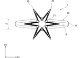
添付図面を参照して本発明の好適な実施形態について説明する。図1~図3に示されるように、本発明の一実施形態に係る歯間清掃具1は、基材部10と、基材部10の少なくとも一部を被覆する軟質部20と、を備えている。歯間清掃具1は、例えば基材部10に形成された1対の接続部30、30によって歯間清掃具1の短手方向D1に例えば10個の歯間清掃具1が並列に接続されて形成された接続体40から個別に切り離されたものである。
基材部10は、使用者が把持する基部11と、基部11の先端から歯間清掃具1の短手方向D1に直交する長手方向D2に延在して、使用者の歯間に挿入される軸部12と、を備えている。なお、本明細書において、基部11から軸部12に向かう側を先端側とし、軸部12から基部11に向かう側を基端側とする。
基部11は、例えば扁平に広がる板状に形成されており、本実施形態では、例えば平たい直方体形状に形成されているが、使用者が把持することができる形状であれば、その他の形状に形成されてもよい。
軸部12は、基部11の一端である先端から長手方向D2に延在している。軸部12は、基部11から連続して扁平な板状に延在する移行部13と、移行部13の先端から軸部12の先端まで細い軸状に延びる先端部14と、を備えている。移行部13は、軸部12の先端に向かうにつれて短手方向D1に沿って規定される幅を減少させるテーパ形状に形成される。
基材部10は例えば合成樹脂材料から成形される。合成樹脂材料としては、例えばポリプロピレン、ポリエチレン、ABS(アクリロニトリル・ブタジエン・スチレン)、ポリブチレンテレフタレート、ポリカーボネート、ポリエチレンテレフタレート、ポリスチレン、ポリアセタール、ポリアミド等を採用することができる。また、合成樹脂材料には、例えば1~30重量%程度の割合でガラス繊維等の繊維素材が添加されてもよい。
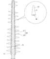
軟質部20は、軸部12の先端部14の少なくとも一部の外周面を被覆する被覆部21と、被覆部21から突き出る複数の突起部22と、を備えている。突起部22は、例えば円錐形状に形成されており、被覆部21の基端から先端まで、軸部12の先端部14の軸心周りに例えば一筋の螺旋状に配置されている。被覆部21の外周面からの突起部22の高さは、被覆部21の基端から先端に向かうにつれて減少する。
軟質部20は、基部10の合成樹脂材料のショアA硬度よりも低いショアA硬度を有する樹脂材料から形成される。樹脂材料としてはエラストマーを採用することができ、エラストマーとしては、スチレン系エラストマー、シリコーン、オレフィン系エラストマー、ポリエステル系エラストマー等が用いられてもよい。エラストマーのショアA硬度は、デュロメータ硬さタイプA(JISK6253)が、10~60であることが好ましい。
本実施形態の歯間清掃具1において、長手方向D2に規定される基材部10の長さL1は例えば45mm~55mmに設定されている。短手方向D1に規定される基部11の幅W1は例えば3mm~10mmに設定されている。また、短手方向D1及び長手方向D2に直交する厚さ方向D3に規定される基部11の厚さT1は例えば0.5mm~10mmに設定されている。
軸部12の軸心に直交する軸部12の先端部14の断面はほぼ正円形状に設定されている。先端部14は、その基端から先端に向かうにつれて縮径するテーパ形状に形成されており、その直径は例えば0.6mm~3.0mmに設定されている。
一方で、長手方向D2に規定される被覆部21の基端から先端までの長さは、例えば10mm~25mmに設定されており、本実施形態では例えば20mmに設定されている。被覆部21は、長手方向D2の同じ位置では均一な厚さで形成されており、その厚さBは例えば0.1mm~2.5mmに設定されている。
図3に示すように、被覆部21との境界となる突起部22の底面(すなわち、円錐の円形の底面)からの突起部22の長さA(すなわち、円錐の底面から頂点までの高さ)は例えば0.1mm~5.0mmに設定されている。本実施形態では、図3から明らかなように、各突起部22の長さAは、被覆部21の基端から先端に向かうにつれて減少する。
各突起部22の底面の面積Mは例えば0.05mm2~0.5mm2に設定されている。この各突起部22の底面の面積Mも長さAと同様に、被覆部21の基端から先端に向かうにつれて減少する。
本実施形態の歯間清掃具1では、軸部12の先端から基端に向かって15mm~20mmの範囲の被覆部21の領域において、突起部22の長さAは1mm~5mmに設定され、被覆部21の厚さBは0.15mm~0.3mmに設定され、軟質部20の材料のショアA硬度Cは30~60に設定される。こうした割合の設定によれば、後述の検証結果で説明するとおり、歯間への挿入のしやすさ及び歯肉への十分なマッサージ力を確保することができる歯間清掃具1を提供することができる。なお、突起部22の長さAが1.83mmに設定される場合、被覆部21の厚さBは0.22mm~0.25mmに設定され、軟質部20の材料のショアA硬度Cは35~45に設定されることがより好ましい。
本発明者らは、上記実施形態の歯間清掃具1の効果の検証を行った。検証にあたって、図4に示すように、実施例1~18に係る歯間清掃具並びに比較例1~10に係る歯間清掃具を製造した。具体的には、軸部の先端から基端に向かって15mm~20mmの範囲の被覆部の領域(軸部の直径1.04mm~1.27mm)において、突起部の長さAを1mm~5mm、被覆部の厚さBを0.05mm~0.5mm、軟質部のショアA硬度Cを10~70にそれぞれ変化させた。
本発明者らは、上述した実施例1~18及び比較例1~10に係る歯間清掃具の挿入のしやすさ(挿入性)及び歯肉へのマッサージ力の観点について、評価者(5人)に当該歯間清掃具を使用してもらった際の評価の聞き取りを行った。挿入性及びマッサージ力の評価は、0点~10点までの数値による11段階評価において実施した。0点は、「歯間に挿入することができなかった」又は「マッサージした感覚が得られなかった」とし、10点は、「歯間に抵抗なく挿入することができた」又は「満足にマッサージすることができた」とした。
以上の数値による評価に基づいて算定された挿入性及びマッサージ力の評価として、評価者の数値の平均が、7.5点以上である場合を「◎」、5点以上7.5点未満である場合を「○」、2.5点以上5点未満である場合を「△」、2.5点未満である場合を「×」とした。挿入性及びマッサージ力の評価を基に、下記の基準に従って総合評価を行った。
[挿入性]
◎ 平均点が7.5以上
○ 平均点が5.0以上7.5未満
△ 平均点が2.5以上5.0未満
× 平均点が2.5未満
[マッサージ力]
◎ 平均点が7.5以上
○ 平均点が5.0以上7.5未満
△ 平均点が2.5以上5.0未満
× 平均点が2.5未満
[総合評価]
○ ○以上である
△ ○又は◎がある一方で△がある
× 1つでも×がある
図4において、比較例4、比較例5、実施例6~11及び比較例6に着目する。これらの例では、突起部の長さA(1.83mm)及び被覆部の厚さB(0.22mm)を同一の条件に設定した。この場合に軟質部のショアA硬度Cを変化させた。軟質部のショアA硬度Cが10及び20にそれぞれ設定された比較例4及び5では、マッサージ力が「×」であり、総合評価も「×」であった。また、軟質部のショアA硬度Cを70に設定した比較例6では、挿入性及びマッサージ力がともに「×」であり、総合評価も「×」であった。一方で、実施例6~11では、一部に「△」があるが、総合評価は「△」又は「○」であった。この結果によれば、突起部の長さAが1.83mmであり、被覆部の厚さBが0.22mmである場合に、軟質部のショアA硬度Cが30~60に設定されることが好ましいことが分かる。
次に、比較例2、比較例3、実施例4及び実施例5に着目する。これらの例では、突起部の長さA(1.83mm)及び軟質部のショアA硬度C(40)を同一の条件に設定した。この場合に被覆部の厚さBを変化させた。厚さBが0.1mm以下である比較例2及び3ではいずれも、挿入性が「◎」であるものの、マッサージ力が「×」であり、総合評価も「×」であった。一方で、実施例4及び5では、挿入性が「◎」又は「○」であり、マッサージ力はともに「△」であり、総合評価は「△」又は「○」であった。この結果によれば、突起部の長さAが1.83mmであり、軟質部のショアA硬度Cが40である場合に、被覆部の厚さBの下限値が0.15であることが分かる。
一方で、実施例12、実施例13、比較例7及び比較例8に着目する。これらの例では、上記と同様に、突起部の長さA(1.83mm)及び軟質部のショアA硬度C(40)を同一の条件に設定した。この場合に被覆部の厚さBを変化させた。厚さBが0.4mm以上である比較例7及び8ではいずれも、マッサージ力が「△」であるものの、挿入性がいずれも「×」であり、総合評価も「×」であった。一方で、厚さBが0.3mm以下である実施例12及び13では、挿入性が「○」又は「△」であり、マッサージ力はともに「△」であり、総合評価は「△」であった。この結果によれば、突起部の長さAが1.83mmであり、軟質部のショアA硬度Cが40である場合に、被覆部の厚さBの上限値が0.3であることが分かる。すなわち、前述の検証結果と合わせると、被覆部の厚さBは0.15~0.3に設定されることが好ましいことが分かる。
次に、実施例1~3及び比較例1に着目する。これらの例では、突起部の長さA(1mm)を同一の条件に設定した一方で、被覆部の厚さB及び軟質部のショアA硬度Cを変化させた。比較例1では、挿入性は「○」であるものの、マッサージ力が「×」であり、総合評価も「×」であった。一方で、実施例1~3では、挿入性及びマッサージ力はともに「△」以上であり、総合評価も「△」以上であった。この結果によれば、上述の結果のとおり、軟質部のショアA硬度Cが10に設定される場合を許容することができないことが分かる。一方で、被覆部の厚さB及び軟質部のショアA硬度Cが上述の結果の数値範囲に含まれる場合、突起部の厚さAが1mmに設定されてもよいことが分かる。
一方で、実施例14~18、比較例9及び比較例10に着目する。これらの例では、被覆部の長さBを上記の許容可能な数値範囲に設定した一方で、突起部の長さA及び軟質部のショアA硬度Cを変化させた。比較例9及び10では、突起部の長さAを3mmや5mmと比較的大きく設定した一方で、軟質部のショアA硬度Cを10に設定したが、やはり軟質部のショアA硬度Cが低すぎて十分なマッサージ力を確保することができなかった。一方で、実施例14~18では、挿入性及びマッサージ力はともに「△」以上であり、総合評価も「△」以上であった。この結果によれば、軟質部のショアA硬度Cが10に設定される場合を許容することができないことが分かる一方で、被覆部の厚さB及び軟質部のショアA硬度Cが上述の数値範囲に含まれる場合、突起部の厚さAは2mm~5mmに設定されてもよいことが分かる。
以上の検証の結果によれば、突起部の長さAが1mm~5mmに設定された場合、被覆部の厚さBが小さすぎると(例えば0.15mm未満)、十分なマッサージ力を確保することができない一方で、被覆部の厚さBが大きすぎると(例えば0.3より大きい)、挿入性が低下することが分かる。また、同様に突起部の長さAが1mm~5mmに設定された場合、軟質部のショアA硬度Cが小さすぎると(例えば30未満)、十分なマッサージ力を確保することができない一方で、軟質部のショアA硬度Cが大きすぎると(例えば60より大きい)、挿入性もマッサージ力も低下することが分かる。したがって、突起部22の長さAが1mm~5mmに設定され、被覆部21の厚さBが0.15mm~0.3mmに設定され、軟質部20の材料のショアA硬度Cが30~60に設定される場合に、挿入性及びマッサージ力のバランスがよいことが分かる。
次に、歯間清掃具1の製造方法について以下に説明する。まず、基材部10の外形を象った第1金型の充填空間に溶融した合成樹脂材料が充填されて基材部10が成形される。その後、基材部10は第1金型から取り出される。続いて、成形された基材部10は、軟質部20の外形を象った第2金型の充填空間内に配置される。充填空間には、溶融したエラストマーが充填され軟質部20が成形される。こうして歯間清掃具1が成形される。歯間清掃具1は、その後、第2金型から取り出される。
以上説明した実施形態は、本発明の理解を容易にするためのものであり、本発明を限定して解釈するためのものではない。実施形態が備える各要素並びにその配置、材料、条件、形状及びサイズ等は、例示したものに限定されるわけではなく適宜変更することができる。また、異なる実施形態で示した構成同士を部分的に置換し又は組み合わせることが可能である。
1…歯間清掃具、10…基材部、11…基部、12…軸部、20…軟質部、21…被覆部、22…突起部、A…突起部の長さ、B…被覆部の厚さ、C…軟質部のショアA硬度
Claims (2)
-
基部と、前記基部から延在する軸部と、を有する基材部と、
前記軸部の先端から基端に向かって少なくとも16mmにわたって前記軸部を被覆する被覆部と、前記被覆部から突き出る複数の突起部と、を有する軟質部と、を備え、
前記軸部の先端から基端に向かって15mm~20mmの範囲の前記被覆部の領域において、前記被覆部の厚さは0.15mm~0.3mmに設定され、前記軟質部を形成する材料のショアA硬度は30~60に設定される、歯間清掃具。
-
前記被覆部の前記領域において、前記被覆部の表面からの前記突起部の長さは1mm~5mmに設定される、請求項1に記載の歯間清掃具。
Applications Claiming Priority (2)
| Application Number | Priority Date | Filing Date | Title |
|---|---|---|---|
| JP2019-042210 | 2019-03-08 | ||
| JP2019042210A JP2020141931A (ja) | 2019-03-08 | 2019-03-08 | 歯間清掃具 |
Publications (1)
| Publication Number | Publication Date |
|---|---|
| WO2020183796A1 true WO2020183796A1 (ja) | 2020-09-17 |
Family
ID=72354834
Family Applications (1)
| Application Number | Title | Priority Date | Filing Date |
|---|---|---|---|
| PCT/JP2019/045070 Ceased WO2020183796A1 (ja) | 2019-03-08 | 2019-11-18 | 歯間清掃具 |
Country Status (2)
| Country | Link |
|---|---|
| JP (2) | JP2020141931A (ja) |
| WO (1) | WO2020183796A1 (ja) |
Citations (3)
| Publication number | Priority date | Publication date | Assignee | Title |
|---|---|---|---|---|
| JP2017000775A (ja) * | 2015-06-12 | 2017-01-05 | サンスター株式会社 | 歯間清掃具 |
| JP2017118959A (ja) * | 2015-12-28 | 2017-07-06 | サンスター株式会社 | 歯間清掃具 |
| US20180193119A1 (en) * | 2016-07-14 | 2018-07-12 | Sunstar Suisse S.A. | Interdental cleaner |
-
2019
- 2019-03-08 JP JP2019042210A patent/JP2020141931A/ja active Pending
- 2019-11-18 WO PCT/JP2019/045070 patent/WO2020183796A1/ja not_active Ceased
-
2025
- 2025-07-01 JP JP2025111224A patent/JP2025129272A/ja active Pending
Patent Citations (3)
| Publication number | Priority date | Publication date | Assignee | Title |
|---|---|---|---|---|
| JP2017000775A (ja) * | 2015-06-12 | 2017-01-05 | サンスター株式会社 | 歯間清掃具 |
| JP2017118959A (ja) * | 2015-12-28 | 2017-07-06 | サンスター株式会社 | 歯間清掃具 |
| US20180193119A1 (en) * | 2016-07-14 | 2018-07-12 | Sunstar Suisse S.A. | Interdental cleaner |
Also Published As
| Publication number | Publication date |
|---|---|
| JP2020141931A (ja) | 2020-09-10 |
| JP2025129272A (ja) | 2025-09-04 |
Similar Documents
| Publication | Publication Date | Title |
|---|---|---|
| JP5806922B2 (ja) | 歯ブラシ | |
| CN102651984B (zh) | 具有设置在手柄内的本体的口腔护理器具 | |
| JP4579345B2 (ja) | 円筒型歯ブラシ | |
| US20230414334A1 (en) | Interdental cleaning tool | |
| JP2013505100A (ja) | 歯ブラシ | |
| WO2016167191A1 (ja) | 歯間ブラシ | |
| JP2020103851A (ja) | 歯間清掃具 | |
| JP7565673B2 (ja) | 歯間清掃具 | |
| JP7212457B2 (ja) | 歯間清掃具 | |
| WO2020137249A1 (ja) | 歯間清掃具 | |
| JP2020141931A (ja) | 歯間清掃具 | |
| JP2013198593A (ja) | 口腔内マッサージ用具 | |
| JP2020103852A (ja) | 歯間清掃具の製造方法 | |
| JP7765885B2 (ja) | 歯間清掃具 | |
| JP7191546B2 (ja) | 歯間清掃具 | |
| JP7252715B2 (ja) | 歯間清掃具 | |
| JP2017000407A (ja) | 歯ブラシ | |
| JP2021176431A (ja) | 歯間清掃具 | |
| JP7369521B2 (ja) | 歯間清掃具 | |
| JP6976831B2 (ja) | 歯間清掃具の製造方法 | |
| JP7395421B2 (ja) | 歯間清掃具セット | |
| JP2018075269A (ja) | 歯ブラシ | |
| JPH11290233A (ja) | 耳掃除器 |
Legal Events
| Date | Code | Title | Description |
|---|---|---|---|
| 121 | Ep: the epo has been informed by wipo that ep was designated in this application |
Ref document number: 19918615 Country of ref document: EP Kind code of ref document: A1 |
|
| NENP | Non-entry into the national phase |
Ref country code: DE |
|
| 122 | Ep: pct application non-entry in european phase |
Ref document number: 19918615 Country of ref document: EP Kind code of ref document: A1 |