WO2020183682A1 - 薄膜材料用機械特性計測装置 - Google Patents
薄膜材料用機械特性計測装置 Download PDFInfo
- Publication number
- WO2020183682A1 WO2020183682A1 PCT/JP2019/010415 JP2019010415W WO2020183682A1 WO 2020183682 A1 WO2020183682 A1 WO 2020183682A1 JP 2019010415 W JP2019010415 W JP 2019010415W WO 2020183682 A1 WO2020183682 A1 WO 2020183682A1
- Authority
- WO
- WIPO (PCT)
- Prior art keywords
- test piece
- pair
- negative pressure
- thin film
- layer
- Prior art date
- Legal status (The legal status is an assumption and is not a legal conclusion. Google has not performed a legal analysis and makes no representation as to the accuracy of the status listed.)
- Ceased
Links
Images







Classifications
-
- G—PHYSICS
- G01—MEASURING; TESTING
- G01N—INVESTIGATING OR ANALYSING MATERIALS BY DETERMINING THEIR CHEMICAL OR PHYSICAL PROPERTIES
- G01N3/00—Investigating strength properties of solid materials by application of mechanical stress
-
- G—PHYSICS
- G01—MEASURING; TESTING
- G01N—INVESTIGATING OR ANALYSING MATERIALS BY DETERMINING THEIR CHEMICAL OR PHYSICAL PROPERTIES
- G01N3/00—Investigating strength properties of solid materials by application of mechanical stress
- G01N3/08—Investigating strength properties of solid materials by application of mechanical stress by applying steady tensile or compressive forces
Definitions
- the present invention relates to a device for measuring mechanical properties of a thin film material using a crystal oscillator, and in particular, enables measurement of mechanical properties of a thin film material having low strength, low elasticity and ultrathinness such as a biological cell membrane. It's about technology.
- a high-sensitivity load sensor using a crystal oscillator (QCR; Quartz Crystal Resonator) is known.
- the load sensor described in Patent Document 1 is that.
- the oscillation frequency changes in exactly proportional to the applied load. It is possible to realize a load sensor capable of highly sensitive, highly accurate, and highly stable measurement.
- a thin film material having the same mechanical properties as the biological cell membrane is required for training of a technique for handling a low-strength biological cell membrane that is low elasticity, ultrathin, and easily destroyed.
- a material with the same low strength, low elasticity, and ultrathinness as the inner limiting membrane is required for training in internal limiting membrane (ILM) ablation surgery and transplant surgery on the retina of the fundus.
- ILM internal limiting membrane
- the conventional thin film mechanical property measuring device does not plan to measure the mechanical properties of the low strength, low elasticity and ultrathin thin film material as described above, and the ultrathin thin film material is fixed and minute. Since it was difficult to measure the strength value, it was not possible to obtain a homogeneous thin film material for training, which was an obstacle to training.
- the present invention has been made in the context of the above circumstances, and an object of the present invention is to measure mechanical properties of a thin film material capable of measuring the mechanical properties of a thin film material having low strength, low elasticity and ultrathinness. To provide the equipment.
- the gist of the first invention is (a) a machine for a thin film material that measures the mechanical properties of the thin film material based on at least the tensile load of the test piece by pulling both ends of the test piece made of the thin film material.
- a characteristic measuring device wherein (b) a pair of negative pressure clamps that fix both ends of the test piece by sucking with negative pressure, and (c) the test piece on one of the pair of negative pressure clamps.
- a thin plate-shaped crystal plate provided in a load transmission path between (d) one of the negative pressure clamps and the tensile load load device is provided on the crystal plate. It is to include a load sensor that detects the magnitude of the applied tensile load.
- the gist of the second invention is that the first invention includes a movement amount measuring device that measures the movement amount of one of the negative pressure clamps in a non-contact manner.
- the gist of the third invention is that, in the first invention or the second invention, the tensile load loading device has a piezoelectric element that outputs the tensile load having a magnitude corresponding to the applied voltage.
- the gist of the fourth invention is that, in any one of the first to third inventions, the liquid tank in which the test piece is immersed in a completely submerged state is provided, and the pair of negative pressure clamps is provided. It has a suction surface parallel to the pulling direction in which a plurality of suction holes for sucking both ends of the test piece are formed, and is arranged in the liquid tank.
- the gist of the fifth invention is that in any one of the first to fourth inventions, the test piece made of the thin film material has a longitudinal shape and is adsorbed by the pair of negative pressure clamps. Both ends and an intermediate portion between the both ends having a width dimension smaller than that of the both end portions are provided, and the width dimension between the end portion and the intermediate portion continuously decreases according to a predetermined radius of curvature. There is something to do.
- the gist of the sixth invention is that in any one of the first to fifth inventions, the load sensor sandwiches the thin plate-shaped crystal plate and the crystal plate on both sides of the crystal plate.
- a crystal oscillator layer having a pair of opposing electrode layers and a pair of holding layers integrally adhered to both sides of the crystal oscillator layer and made of the same material as the quartz oscillator layer are included. It is characterized by that.
- the gist of the seventh invention is that, in the fourth invention, the load sensor is a crystal provided with a thin plate-shaped crystal plate and a pair of electrode layers facing each other with the crystal plate sandwiched on both sides of the crystal plate.
- a pair of holding layers integrally adhered to both sides of the crystal unit and the crystal unit and made of the same material as the crystal unit, and one end of the crystal unit and the pair of holding layers. Adhesion to the first communication hole penetrating the portions, the second communication hole penetrating the other ends of the crystal oscillator layer and the pair of holding layers, and one holding layer of the pair of holding layers.
- the pair of holding layers having a bottom layer having a connection recess connecting the first communication hole and the second communication hole opening to the one holding layer, and the suction surface having a plurality of suction holes opening.
- the gist of the eighth invention is that in any one of the first to seventh inventions, the tensile load load device is applied to the test piece whose both ends are fixed to the pair of negative pressure clamps.
- An electronic control device that calculates the mechanical properties of the test piece based on at least one of the tensile load detected by the load sensor and the elongation amount of the test piece when the load of the tensile load is started. To prepare.
- the test piece fixed by attracting both ends to the pair of negative pressure clamps using negative pressure is pulled from the tensile load load device.
- the tensile load is detected by the load sensor, so that the mechanical properties of a thin film material having low strength, low elasticity, and ultrathinness can be measured.
- the moving amount measuring device for measuring the moving amount of one of the negative pressure clamps in a non-contact manner is included. In this way, it is based on at least one of the maximum tensile load at the time when the tensile load detected by the load sensor changes from increasing to decreasing and the elongation amount of the test piece when the maximum tensile load is generated. Therefore, the mechanical properties of the test piece can be calculated.
- the tensile load loading device has a piezoelectric element that outputs the tensile load having a magnitude corresponding to the applied voltage.
- the tensile load output from the piezoelectric element can be controlled with a weak value, so that the mechanical properties of a thin film material having low strength, low elasticity, and ultrathinness can be measured.
- a liquid tank in which the test piece is immersed in a completely submerged state is provided, and the pair of negative pressure clamps attract a plurality of both ends of the test piece. It has a suction surface parallel to the tension direction in which the suction holes of the above are formed, and is arranged in the liquid tank. In this way, since the test piece is clamped by a pair of negative pressure clamps while being immersed in the liquid tank in a completely submerged state, the measurement accuracy is improved without being affected by the surface tension of the liquid in the liquid tank. ..
- the mechanical properties of the thin film material can be measured slowly over time while immersed in the liquid tank, there is no change in the thin film material during the measurement, and the machine of the thin film material with low strength, low elasticity and ultrathinness. It is possible to measure the physical properties.
- the test piece made of the thin film material has a longitudinal shape, and is between both ends adsorbed by the pair of negative pressure clamps and the both ends.
- the shape includes an intermediate portion having a width dimension smaller than that of both end portions, and the width dimension between the both end portions and the intermediate portion is continuously reduced according to a predetermined radius of curvature.
- the load sensor includes the thin plate-shaped crystal plate and a pair of electrode layers facing each other with the crystal plate sandwiched on both sides of the crystal plate. It includes a crystal oscillator layer and a pair of holding layers integrally bonded to both sides of the crystal oscillator layer and made of the same material as the quartz oscillator layer. In this way, there is no difference in thermal expansion between the crystal oscillator layer and the pair of holding layers integrally adhered to both sides of the crystal oscillator layer, so that the crystal oscillator layer is not affected by temperature changes. , Reliable measurement can be performed.
- the load sensor is a crystal provided with a thin plate-shaped crystal plate and a pair of electrode layers facing each other with the crystal plate sandwiched on both sides of the crystal plate.
- a pair of holding layers integrally adhered to both surfaces of the vibrator layer and the crystal oscillator layer and made of the same material as the crystal oscillator layer, and one end of the crystal oscillator layer and the pair of holding layers. Adhesion to the first communication hole penetrating the portions, the second communication hole penetrating the other ends of the crystal oscillator layer and the pair of holding layers, and one holding layer of the pair of holding layers.
- the pair of holding layers having a bottom layer having a connection recess connecting the first communication hole and the second communication hole that open to the one holding layer, and the suction surface that opens a plurality of suction holes.
- a suction plate that is adhered to the other holding layer of the above and functions as the negative pressure clamp by covering the first communication hole that opens to the other holding layer, and the holding of the other of the pair of holding layers. It includes a connecting plate that is adhered to the layer and connects the second communication hole that opens to the other holding layer to the negative pressure pipe.
- the mechanical property measuring device for thin film materials of the eighth invention when a tensile load is started from the tensile load load device on the test piece whose both ends are fixed to the pair of negative pressure clamps.
- An electronic control unit for calculating the mechanical properties of the test piece based on at least one of the tensile load detected by the load sensor and the elongation amount of the test piece is provided. In this way, the mechanical properties of the low-strength, low-elasticity, and ultra-thin thin film material can be automatically measured.
- FIG. 1 It is a top view which shows the test piece used for the mechanical property measuring apparatus for thin film materials of this invention. It is a perspective view which shows the punching jig for manufacturing the test piece of FIG. It is the schematic explaining the structure of the mechanical property measuring apparatus for thin film material of one Example of this invention. It is a perspective view which shows the suction plate used for the fixed side negative pressure clamp and the movable side negative pressure clamp of the mechanical property measuring apparatus for thin film material of FIG. 3, respectively. It is a perspective view which shows the laminated structure of the load sensor used for the mechanical property measuring apparatus for thin film material of FIG. 3 by separating each layer. It is a figure explaining the manufacturing process of the crystal oscillator layer shown in FIG.
- FIG. 1 is a plan view showing a test piece 12 made of a thin film material, which is a measurement target of the mechanical property measuring device 10 for a thin film material, which is an embodiment of the present invention.
- the thin film material is, for example, a thin plate formed by expanding and binding the inner edges of Mueller cells, in other words, a biological cell membrane such as the inner limiting membrane (ILM) on the surface of the retina of the fundus and in contact with the vitreous body. It is a low-strength, low-elasticity, and ultra-thin material having a thickness of about 3 ⁇ m.
- ILM inner limiting membrane
- the test piece 12 has, for example, a pair of long ends having a total length L of 2.5 mm and a relatively large width because the width dimension W1 is 1.0 mm, that is, in the longitudinal direction.
- An intermediate portion 12b having a relatively small width is provided between both end portions 12a because the width dimension W2 is 0.3 mm.
- Both end portions 12a are portions that are clamped by negative pressure by a pair of fixed-side negative pressure clamps 20 and movable-side negative pressure clamps 22, which will be described later.
- FIG. 2 is a punching jig 14 for producing the test piece 12 having the above shape.
- the punching jig 14 is configured such that a ribbon-shaped wire having a height of about 120 ⁇ m and a thickness of about 5 ⁇ m is bent in an annular shape so as to form a frame having the same shape as the test piece 12.
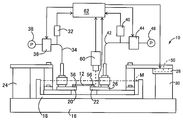
- the mechanical property measuring device 10 for a thin film material is fixed to a base 16 and a liquid tank 18 in which a liquid M such as physiological saline is stored, and in the liquid tank 18. It includes a pair of fixed side negative pressure clamps 20 and movable side negative pressure clamps 22, a fixed side negative pressure clamp support device 24, and a movable side negative pressure clamp support device 30.
- the fixed-side negative pressure clamp support device 24 is provided on the base 16 and supports the fixed-side negative pressure clamp 20 in a fixed position.
- the movable side negative pressure clamp support device 30 is provided on the base 16 so as to sandwich the fixed side negative pressure clamp support device 24 and the liquid tank 18, and the movable side negative pressure clamp 22 is placed on the load sensor 26 and the tensile load. It is supported via a load device 28.
- the fixed side negative pressure clamp 20 is connected to the first negative pressure source 38 via the first negative pressure pipe 34 to which the first pressure sensor 32 is connected and the first pressure adjusting valve 36.
- the movable side negative pressure clamp 22 is connected to the second negative pressure source 48 via the second negative pressure pipe 42 to which the second pressure sensor 40 is connected and the second pressure adjusting valve 44.
- the tensile load load device 28 includes a piezoelectric element 50 that deforms according to an applied voltage as a driving force source, and by moving the movable side negative pressure clamp 22 in the horizontal direction, the pair of fixed side negative pressure clamps 20 and The test piece 12 in a state where both ends 12a are clamped by the movable side negative pressure clamp 22 and is completely submerged in the liquid tank 18 has a size corresponding to the command voltage from the electronic control device 62 (see FIG. 13) described later. A tensile load is applied to the test piece 12 in the longitudinal direction, that is, in the horizontal direction.
- the fixed-side negative pressure clamp 20 and the movable-side negative pressure clamp 22 each include a suction plate 56 having a suction surface 54 on which a plurality of suction holes 52 shown in FIG. 4 are formed.
- the fixed-side negative pressure clamp 20 has a communication passage for communicating the first negative pressure pipe 34 and the space on the back surface of the suction plate 56, and the suction surface 54 of the suction plate 56 is formed on both ends 12a of the test piece 12. One of them is clamped (fixed) by being sucked through the suction hole 52.
- the movable side negative pressure clamp 22 has a communication passage for communicating the second negative pressure pipe 42 and the space on the back surface of the suction plate 56, and the suction surface 54 of the suction plate 56 is formed on both ends 12a of the test piece 12. The other is clamped (fixed) by sucking through the suction hole 52.
- the suction hole 52 has a diameter set in advance so that both end portions 12a of the test piece 12 are not torn, for example, a diameter of 13 ⁇ m or less, preferably 10 ⁇ m or less.
- the suction plate 56 is manufactured by etching from, for example, a silicon substrate.
- the suction surface 54 of the suction plate 56 of the fixed side negative pressure clamp 20 and the movable side negative pressure clamp 22 is parallel to the horizontal plane. That is, the fixed side negative pressure clamp 20 and the movable side negative pressure clamp 22 are supported so as to be parallel to the pulling direction of the test piece 12.
- the mechanical property measuring device 10 for a thin film material is provided with, for example, an image pickup device 60 having a CCD element and an electronic control device 62.
- the imaging device 60 images the test piece 12 in which both ends 12a are clamped to the fixed side negative pressure clamp 20 and the movable side negative pressure clamp 22.
- the electronic control device 62 displays the image of the test piece 12 on the image monitor 64 based on the image signal output from the image pickup device 60, and measures the elongation amount h of the test piece 12 by using image processing.
- the image pickup device 60 and the electronic control device 62 also function as a movement amount measuring device that non-contactly measures the movement amount of the movable side negative pressure clamp 22 corresponding to the extension amount h of the test piece 12.
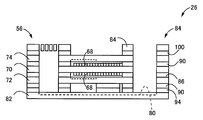
- FIG. 5 is a perspective view illustrating the laminated structure of the load sensor 26 with each layer separated.
- the load sensor 26 includes a crystal oscillator layer 70, a pair of holding layers 72 and 74, a first communication hole 76, a second communication hole 78, a bottom layer 82, and a suction plate 56. , And a connection plate 84.
- the crystal oscillator layer 70 includes a thin plate-shaped single crystal crystal plate and a pair of electrode layers 68 facing each other with the crystal plate sandwiched on both sides of the crystal plate.
- the pair of holding layers 72 and 74 are integrally adhered to both surfaces of the crystal oscillator layer 70, and are composed of a single crystal crystal plate which is the same material as the crystal oscillator layer 70.
- the first communication hole 76 penetrates the crystal oscillator layer 70 and one ends of the pair of holding layers 72 and 74 in the plate thickness direction, respectively, and the second communication hole 78 penetrates the crystal oscillator layer 70 and the pair of holding layers 72, respectively. And 74 penetrate the other end in the plate thickness direction, respectively.
- the bottom layer 82 is adhered to the lower surface of one of the pair of holding layers 72 and 74, which is the lower side, and opens to the lower holding layer 72 with the first communication hole 76 and the second communication. It has a connection recess 80 for connecting the holes 78.
- the suction plate 56 has a suction surface 54 through which a plurality of suction holes 52 are opened, is adhered to the upper holding layer 74 of the pair of holding layers 72 and 74, and opens to the upper holding layer 74. By covering the first communication hole 76, it functions as a movable side negative pressure clamp 22.
- the connection plate 84 is adhered to the upper holding layer 74 of the pair of holding layers 72 and 74, and the second communication hole 78 that opens into the upper holding layer 74 is connected to the above-mentioned second negative pressure pipe 42. There is.
- the bottom layer 82 is composed of, for example, a single crystal crystal plate, and the adsorption plate 56 and the connection plate 84 are composed of a silicon wafer.
- the pair of holding layers 72 and 74 are provided with recesses 77 so that the pair of electrode layers 68 do not come into contact with the pair of holding layers 72 and 74.
- each of the pair of electrode layers 68 is provided with terminals 69 for connecting to an oscillation circuit 106, which will be described later.
- the recess 77 may have a shape in which the electrode layer 68 and the pair of holding layers 72 and 74 do not come into contact with each other.
- the crystal oscillator layer 70 that is, the crystal plate is inserted in the load transmission path between the movable side negative pressure clamp 22 and the tensile load load device 28, and the crystal oscillator layer 70, that is, the crystal plate is said.
- the magnitude of the tensile load F applied to the crystal oscillator layer 70 based on the frequency change output from the oscillation circuit (see FIG. 11) including the crystal oscillator layer 70, which is generated in response to the strain applied to the crystal plate. Is now detected.
- the arrow indicated by the broken line entering from the suction plate 56 and exiting from the connecting plate 84 indicates the flow path in which the liquid M is sucked by the second negative pressure source 48.
- the load sensor 26 and the movable side negative pressure clamp 22 are integrally configured.
- the fixed-side negative pressure clamp 20 is made of a material different from that of the load sensor 26 and has a different layer structure from which the crystal oscillator layer 70 and the holding layer 72 are removed, the load sensor 26 shown in FIG. 5 is shown. It has a structure similar to that of.
- FIG. 6 is a diagram illustrating a manufacturing process of the crystal oscillator layer 70.
- electrodes 68 and terminals 69 are formed on both surfaces of the crystal oscillator layer 70 by the Cr / Au thin film by performing sputtering through a patterned photoresist film.
- the materials of the adhesive layer 86 for example, Cr and Au, are sequentially formed on a photoresist (not shown) from which the pattern of the shape corresponding to the adhesive layer 86 has been removed by using a sputtering apparatus, and then the photo of the photoresist is formed. By peeling off the resist, the adhesive layer 86 is selectively formed on the lower surface of the crystal transducer layer 70.
- a photoresist film 88 having a shape corresponding to the first communication hole 76 and the second communication hole 78 is formed on the upper surface of the crystal oscillator layer 70.
- the photoresist film 88 is removed after the first communication hole 76 and the second communication hole 78 are formed by sandblasting from above the photoresist film 88.
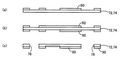
- FIG. 7 is a diagram illustrating a manufacturing process of the pair of holding layers 72 and 74.
- the material of the adhesive layer 90 for example, Cr and Au, is sequentially sputtered on one surface of the holding layers 72 and 74 from a photoresist (not shown) in which a pattern having a shape corresponding to the adhesive layer 90 is removed.
- the adhesive layer 90 is selectively formed on one surface of the holding layers 72 and 74 by forming a film using the film and then peeling off the photoresist.
- a photoresist film 92 having a shape corresponding to the first communication hole 76 and the second communication hole 78 is formed on the other surfaces of the holding layers 72 and 74.
- the photoresist film 92 is removed after the first communication hole 76 and the second communication hole 78 are formed from above the photoresist film 92 by sandblasting.
- FIG. 8 is a diagram illustrating a manufacturing process of the bottom layer 82.
- the materials of the adhesive layer 94 such as Cr and Au, are sequentially sputtered on the upper surface of the bottom layer 82 made of, for example, a quartz plate, on a photoresist (not shown) having a pattern having a shape corresponding to the adhesive layer 94.
- the adhesive layer 94 is selectively formed on one surface of the bottom layer 82 by forming a film using an apparatus and then peeling off the photoresist.
- FIG. 8B a photoresist film 96 having a shape corresponding to the connection recess 80 is formed on the bottom layer 82.
- the photoresist film 96 is removed after the connection recess 80 is formed from above the photoresist film 96 by sandblasting.
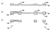
- FIG. 9 is a diagram illustrating a manufacturing process of the suction plate 56 and the connection plate 84.
- the materials of the adhesive layer 100 such as Cr and Au, are sequentially applied to the lower surface of the silicon layer 98 made of a silicon single crystal from a photoresist (not shown) in which a pattern having a shape corresponding to the adhesive layer 100 is removed.
- the adhesive layer 100 is selectively formed on the lower surface of the silicon layer 98 by forming a film using a sputtering device and then peeling off the photoresist.
- FIG. 9B a photoresist film 102 having a shape corresponding to the adsorption plate 56 and the connection plate 84 is formed on the upper surface of the silicon layer 98.
- the photoresist film 102 is removed after the adsorption plate 56 and the connection plate 84 are formed by sandblasting from above the photoresist film 102.
- FIG. 10 is a diagram illustrating a joining process using the crystal oscillator layer 70, the pair of holding layers 72 and 74, the bottom layer 82, the suction plate 56, and the connecting plate 84 manufactured as described above.
- the adhesive layers 86, 90, 94, and 100 are formed by atomic diffusion bonding.
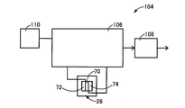
- the load sensor 26 is assembled by being bonded to each other. This bonding may be performed all at once, or may be performed in divided steps.
- FIG. 11 is a diagram illustrating the configuration of the electric circuit 104 including the load sensor 26 of this embodiment.
- the electric circuit 104 reads the frequency of the periodic signal output from the load sensor 26, the oscillation circuit 106 for continuously oscillating the crystal oscillator layer 70 which is the main part of the load sensor 26, and the oscillation circuit 106.
- the frequency counter 108 and the power supply circuit 110 for supplying power to the oscillation circuit 106 and the like are included.
- the oscillation circuit 106 is composed of a Colpitts type oscillation circuit which is generally used as an oscillation circuit of the crystal oscillator layer 70, for example.
- FIG. 12 shows the results of a tensile load load experiment using the electric circuit 104 configured as described above.
- the output frequency f (Hz) with respect to the tensile load F (mN) of the load sensor 26 is measured, and the graph shown in FIG. 12 is obtained.
- FIG. 13 is a diagram illustrating the configuration of the load measuring system 112 provided in the mechanical property measuring device 10 for thin film materials.
- the electronic control unit 62 processes the input signal according to a program stored in advance, measures the mechanical properties of the test piece 12 made of the thin film material, and outputs the signal.
- the test piece holding jig 116 shown in FIG. 14 was used to hold both ends 12a of the test piece 12 in the liquid tank 18 with the suction plate 56 of the fixed side negative pressure clamp 20 and the movable side negative pressure clamp 22.
- the test piece 12 is clamped by the fixed side negative pressure clamp 20 and the movable side negative pressure clamp 22 by adsorbing them to the suction plate 56 by negative pressure after placing them on the respective surfaces.
- the electronic control device 62 drives the piezoelectric element 50 via the drive control circuit 114 to apply the tensile load F (mN) from the tensile load load device 28 to the test piece 12 at a predetermined increasing rate. , The elongation amount h (mm) of the test piece 12 is measured.
- the electronic control device 62 has, for example, an average elongation rate An (mm / mN) of the test piece 12, an elongation amount Af (mm) per a preset constant tensile load Ft (mN), and a preset constant elongation.
- the mechanical properties of the test piece 12 such as the tensile load Fa (mN) per amount At (mm) are set to the tensile load F (mN) applied from the tensile load load device 28 and the extension amount h (mm) of the test piece 12. Calculate based on.
- the electronic control device 62 applies, for example, the maximum tensile strength of the test piece 12, that is, the maximum tensile load Fmax leading to relaxation or breakage, from the tensile load F (mN). ) Is calculated based on the maximum value.
- the maximum value of the tensile load F (mN) is a value at the time when the tensile load F (mN) changes from an increase to a decrease.
- the test piece holding jig 116 has a width dimension larger than the width dimension of the test piece 12, and can be used in a holding case 120 having a storage chamber 118 having an opening at one end and a storage chamber 118 of the holding case 120.
- a cylinder 124 connected via a flexible tube 122 and an operating piston 126 slidably fitted to the cylinder 124 are provided, and the test piece 12 is held together with the liquid in the holding case 120 by pulling out the operating piston 126.
- the test piece 12 is pushed out from the opening of the storage chamber 118 by sucking the liquid together with the liquid into the storage chamber 118 and pushing the operation piston 126.
- both ends 12a of the test piece 12 made of a low-strength, low-elasticity, and ultrathin biological cell membrane having a thickness of, for example, about 1 to 3 ⁇ m are projected from the opening of the accommodation chamber 118.
- the fixed side negative pressure clamp 20 and the movable side negative pressure clamp 22 can be easily placed on the suction plate 56.
- both ends are fixed by suction using negative pressure by a pair of fixed-side negative pressure clamps 20 and movable-side negative pressure clamps 22.
- the load sensor 26 detects the tensile load F. Therefore, the test piece is a thin film material having low strength, low elasticity, and ultra-thinness. Twelve mechanical properties can be measured.
- the mechanical property measuring device 10 for thin film materials of this embodiment the amount of movement of one of the pair of fixed-side negative pressure clamps 20 and the movable-side negative pressure clamp 22, that is, the test piece.
- a movement amount measuring device imaging device 60 and an electronic control device 62 for measuring the extension amount h of 12 in a non-contact manner is included.
- the mechanical properties of the test piece 12 can be calculated based on at least one of the tensile load F detected by the load sensor 26 and the elongation amount h of the test piece 12.
- the tensile load loading device 28 has a piezoelectric element 50 that outputs a tensile load F having a size corresponding to the applied voltage.
- the tensile load F output from the piezoelectric element 50 can be controlled with a weak value, so that the mechanical properties of the test piece 12 made of a thin film material having low strength, low elasticity and ultrathinness can be measured. be able to.
- a liquid tank 18 in which the test piece 12 is immersed in a completely submerged state is provided, and a pair of fixed side negative pressure clamps 20 and a movable side negative pressure clamp 20 are provided.
- Reference numeral 22 denotes a suction surface 54 parallel to the direction of the tensile load F, in which a plurality of suction holes 52 for sucking both end portions 12a of the test piece 12 are formed, and is arranged in the liquid tank 18.
- the test piece 12 is clamped by the pair of fixed-side negative pressure clamps 20 and movable-side negative pressure clamps 22 in a state of being completely submerged in the liquid tank 18, so that the liquid in the liquid tank 18 is used.
- the measurement accuracy is improved without being affected by the surface tension of. Further, since the mechanical properties of the test piece 12 made of the thin film material can be slowly measured over time while immersed in the liquid tank 18, the test piece 12 does not change during the measurement, and has low strength, low elasticity and low elasticity. The mechanical properties of the test piece 12 made of an ultrathin thin film material can be measured.
- the test piece 12 made of a thin film material has a longitudinal shape and is attracted to a pair of fixed side negative pressure clamps 20 and a movable side negative pressure clamp 22. Both end portions 12a and an intermediate portion 12b between both end portions 12a having a width dimension smaller than that of both end portions 12a are provided, and the width dimension between both end portions 12a and the intermediate portion 12b is continuous according to a predetermined radius of curvature. It is a shape that is decreasing. Therefore, since the stress is concentrated on the intermediate portion 12b, the mechanical properties of the test piece 12 made of the thin film material can be stably measured.
- the load sensor 26 is a thin plate-shaped single crystal crystal plate, and a pair of facing crystal plates on both sides of the crystal plate.
- the load sensor 26 has a thin plate shape and a pair of electrode layers facing each other with the crystal plate sandwiched between the single crystal crystal plate and both sides of the crystal plate.
- a pair of holding layers 72 and 74 integrally adhered to both surfaces of the crystal oscillator layer 70 including the crystal oscillator layer 70 and made of the same material as the crystal oscillator layer 70, and a crystal oscillator.
- connection recess 80 that is adhered to the lower holding layer 72 of the pair of holding layers 72, 74 and connects the first communication hole 76 and the second communication hole 78 that open to the lower holding layer 72.
- a first communication hole that has a bottom layer 82 and a suction surface 54 through which a plurality of suction holes 52 are opened, is adhered to the upper holding layer 74 of the pair of holding layers 72 and 74, and opens in the upper holding layer 74.
- a suction plate 56 that functions as a negative pressure clamp by covering 76, and a second communication hole 78 that is adhered to the upper holding layer 74 of the pair of holding layers 72 and 74 and opens to the upper holding layer 74. 2 Includes a connection plate 84 connected to the negative pressure pipe 42. In this way, since the mechanical property measuring device 10 for thin film materials becomes small, it is possible to suitably measure even a test piece 12 made of a minute thin film material.
- a tensile load is applied to the test piece 12 in which both ends 12a are fixed to the pair of fixed side negative pressure clamps 20 and the movable side negative pressure clamp 22.
- the mechanical properties of the test piece 12 are calculated based on at least one of the tensile load F detected by the load sensor 26 and the elongation amount h of the test piece 12.
- the electronic control device 62 is provided. In this way, the mechanical properties of the test piece 12 made of a thin film material having low strength, low elasticity and ultrathinness can be automatically measured.
- the crystal oscillator layer 70 and the pair of holding layers 72 and 74 are bonded by atomic diffusion bonding via the adhesive layers 86 and 90, but they are bonded in a mirror surface state. It may be adhered by molecular bonding via a surface.
Landscapes
- Physics & Mathematics (AREA)
- Health & Medical Sciences (AREA)
- Life Sciences & Earth Sciences (AREA)
- Chemical & Material Sciences (AREA)
- Analytical Chemistry (AREA)
- Biochemistry (AREA)
- General Health & Medical Sciences (AREA)
- General Physics & Mathematics (AREA)
- Immunology (AREA)
- Pathology (AREA)
- Investigating Strength Of Materials By Application Of Mechanical Stress (AREA)
Abstract
低強度、低弾性且つ極薄の薄膜材料の機械的性質を測定することができる薄膜材料用機械特性計測装置を提供する。 薄膜材料用機械特性計測装置10であって、試験片12の両端部を負圧を用いて吸着することで固定する一対の負圧クランプ20,22と、一方の負圧クランプ22に試験片12に対する引張荷重を与える引張荷重負荷装置28と、一方の負圧クランプ22と引張荷重負荷装置28との間の荷重伝達経路に設けられた薄板形状の水晶板を有し、水晶板に印加される引張荷重の大きさを検出する荷重センサ26とを、含む。このようにすれば、試験片12に対して引張荷重負荷装置28から引張荷重が負荷されるとき、荷重センサ26によって引張荷重が検出されるので、低強度、低弾性且つ極薄の薄膜材料である試験片12の機械的性質を測定することができる。
Description
本発明は、水晶振動子を用いた薄膜材料の機械特性測定装置に係るものであり、特に、生体細胞膜のような低強度、低弾性且つ極薄の薄膜材料の機械特性の計測を可能とする技術に関するものである。
水晶振動子(QCR;Quartz Crystal Resonator)を用いた高感度の荷重センサが知られている。例えば特許文献1に記載された荷重センサがそれである。かかる水晶振動子を用いた荷重センサにおいては、薄板状とされた水晶振動子に面方向の荷重を加えた場合に、その発振周波数が加えた荷重に正確に比例して変化することに基づいて、高感度、高精度、高安定の計測が可能な荷重センサを実現し得る。
ところで、医療の進歩に伴って、低弾性且つ極薄であって容易に破壊される低強度の生体細胞膜を取り扱う手技のトレーニングのために、その生体細胞膜と同様の機械特性を有する薄膜材料が求められている。たとえば、眼底の網膜上の内境界膜(ILM:Internal Limiting Membrane)の剥離手術や移植手術のトレーニングのために、内境界膜と同様の低強度、低弾性且つ極薄の材料が求められている。
しかしながら、従来の薄膜の機械特性計測装置では、上記のような低強度、低弾性且つ極薄の薄膜材料の機械的性質の計測を予定しておらず、極薄の薄膜材料の固定、微小な強度値の計測が困難であるため、均質なトレーニング用薄膜材料を入手することができず、トレーニングの障害となっていた。
本発明は、以上の事情を背景としてなされたものであり、その目的とするところは、低強度、低弾性且つ極薄の薄膜材料の機械的性質を測定することができる薄膜材料用機械特性計測装置を提供することにある。
第1発明の要旨とするところは、(a)薄膜材料製の試験片の両端部を引っ張ることで前記試験片の少なくとも引張荷重に基づいて前記薄膜材料の機械的性質を計測する薄膜材料用機械特性計測装置であって、(b)前記試験片の両端部を負圧を用いて吸着することで固定する一対の負圧クランプと、(c)前記一対の負圧クランプの一方に前記試験片に対する引張荷重を与える引張荷重負荷装置と、(d)前記一方の負圧クランプと前記引張荷重負荷装置との間の荷重伝達経路に設けられた薄板形状の水晶板を有し、前記水晶板に印加される前記引張荷重の大きさを検出する荷重センサとを、含むことにある。
第2発明の要旨とするところは、第1発明において、前記一方の負圧クランプの移動量を非接触で計測する移動量計測装置を、含むことにある。
第3発明の要旨とするところは、第1発明または第2発明において、前記引張荷重負荷装置は、印加された電圧に応じた大きさの前記引張荷重を出力する圧電素子を有するものである。
第4発明の要旨とするところは、第1発明から第3発明のいずれか1の発明において、前記試験片が全没状態で浸漬される液槽が備えられ、前記一対の負圧クランプは、前記試験片の両端部を吸着する複数の吸着穴が形成された、前記引張り方向に平行な吸着面を有し、前記液槽内に配置されていることにある。
第5発明の要旨とするところは、第1発明から第4発明のいずれか1の発明において、前記薄膜材料製の試験片は、長手状であって、前記一対の負圧クランプに吸着される両端部と、前記両端部の間において前記両端部よりも幅寸法が小さい中間部とを備え、前記端部と前記中間部との間の幅寸法は所定の曲率半径にしたがって連続的に減少していることにある。
第6発明の要旨とするところは、第1発明から第5発明のいずれか1の発明において、前記荷重センサは、前記薄板形状の水晶板と、前記水晶板の両面に前記水晶板を挟んで対向する一対の電極層とを備えた水晶振動子層と、前記水晶振動子層の両面に一体的に接着され、前記水晶振動子層と同じ材料から構成された一対の保持層と、を含むことを特徴とする。
第7発明の要旨とするところは、第4発明において、前記荷重センサは、前記薄板形状の水晶板と前記水晶板の両面に前記水晶板を挟んで対向する一対の電極層とを備えた水晶振動子層と、前記水晶振動子層の両面に一体的に接着され、前記水晶振動子層と同じ材料から構成された一対の保持層と、前記水晶振動子層および前記一対の保持層の一端部をそれぞれ貫通する第1連通穴、および前記水晶振動子層および前記一対の保持層の他端部をそれぞれ貫通する第2連通穴と、前記一対の保持層のうちの一方の保持層に接着され、前記一方の保持層に開口する前記第1連通穴および第2連通穴を接続する接続凹所を有する底層と、複数の吸着穴が開口する前記吸着面を有して前記一対の保持層のうちの他方の保持層に接着され、前記他方の保持層に開口する前記第1連通穴を覆うことで前記負圧クランプとして機能する吸着板と、前記一対の保持層のうちの他方の保持層に接着され、前記他方の保持層に開口する前記第2連通穴を負圧配管に接続する接続板とを、含むことを特徴とする。
第8発明の要旨とするところは、第1発明から第7発明のいずれか1の発明において、前記一対の負圧クランプに両端部が固定された前記試験片に対して前記引張荷重負荷装置から引張荷重の負荷が開始されたとき、前記荷重センサにより検出された引張荷重と、前記試験片の伸長量との少なくとも一方に基づいて、前記試験片の機械的性質を算出する電子制御装置を、備えることにある。
第1発明の薄膜材料用機械特性計測装置によれば、前記一対の負圧クランプに両端部が負圧を用いて吸着することで固定された前記試験片に対して前記引張荷重負荷装置から引張荷重が負荷されるとき、前記荷重センサによって前記引張荷重が検出されるので、低強度、低弾性且つ極薄の薄膜材料の機械的性質を測定することができる。
第2発明の薄膜材料用機械特性計測装置によれば、前記一方の負圧クランプの移動量を非接触で計測する移動量計測装置を、含む。このようにすれば、前記荷重センサにより検出された引張荷重が増加から減少に変化した時点の最大引張荷重と、前記最大引張荷重が発生したときの前記試験片の伸長量との少なくとも一方に基づいて、前記試験片の機械的性質を算出することができる。
第3発明の薄膜材料用機械特性計測装置によれば、前記引張荷重負荷装置は、印加された電圧に応じた大きさの前記引張荷重を出力する圧電素子を有する。このようにすれば、圧電素子から出力する引張荷重を微弱な値で制御することができるので、低強度、低弾性且つ極薄の薄膜材料の機械的性質を測定することができる。
第4発明の薄膜材料用機械特性計測装置によれば、前記試験片が全没状態で浸漬される液槽が備えられ、前記一対の負圧クランプは、前記試験片の両端部を吸着する複数の吸着穴が形成された、前記引張り方向に平行な吸着面を有し、前記液槽内に配置されている。このようにすれば、試験片が液槽に全没状態で浸漬された状態で一対の負圧クランプによりクランプされるので、液槽内の液の表面張力の影響がなく、測定精度が高められる。また、液槽に浸漬された状態で薄膜材料の機械的性質を時間をかけてゆっくりと測定できるので、測定中における薄膜材料の変化がなく、低強度、低弾性且つ極薄の薄膜材料の機械的性質を測定することができる。
第5発明の薄膜材料用機械特性計測装置によれば、前記薄膜材料製の試験片は、長手状であって、前記一対の負圧クランプに吸着される両端部と、前記両端部の間において前記両端部よりも幅寸法が小さい中間部とを備え、前記両端部と前記中間部との間の幅寸法は所定の曲率半径にしたがって連続的に減少している形状である。このようにすれば、薄膜材料の機械的性質を安定して計測できる。
第6発明の薄膜材料用機械特性計測装置によれば、前記荷重センサは、前記薄板形状の水晶板と、前記水晶板の両面に前記水晶板を挟んで対向する一対の電極層とを備えた水晶振動子層と、前記水晶振動子層の両面に一体的に接着され、前記水晶振動子層と同じ材料から構成された一対の保持層と、を含む。このようにすれば、水晶振動子層と、その水晶振動子層の両面に一体的に接着された一対の保持層との間の熱膨張差がないので、温度変化に対して影響を受けず、信頼性のある計測を行なうことができる。
第7発明の薄膜材料用機械特性計測装置によれば、前記荷重センサは、前記薄板形状の水晶板と前記水晶板の両面に前記水晶板を挟んで対向する一対の電極層とを備えた水晶振動子層と、前記水晶振動子層の両面に一体的に接着され、前記水晶振動子層と同じ材料から構成された一対の保持層と、前記水晶振動子層および前記一対の保持層の一端部をそれぞれ貫通する第1連通穴、および前記水晶振動子層および前記一対の保持層の他端部をそれぞれ貫通する第2連通穴と、前記一対の保持層のうちの一方の保持層に接着され、前記一方の保持層に開口する前記第1連通穴および第2連通穴を接続する接続凹所を有する底層と、複数の吸着穴が開口する前記吸着面を有して前記一対の保持層のうちの他方の保持層に接着され、前記他方の保持層に開口する前記第1連通穴を覆うことで前記負圧クランプとして機能する吸着板と、前記一対の保持層のうちの他方の保持層に接着され、前記他方の保持層に開口する前記第2連通穴を負圧配管に接続する接続板とを、含む。このようにすれば、薄膜材料用機械特性計測装置が小型となるので、微小な薄膜材料に対しても好適に計測することができる。
第8発明の薄膜材料用機械特性計測装置によれば、前記一対の負圧クランプに両端部が固定された前記試験片に対して前記引張荷重負荷装置から引張荷重の負荷が開始されたとき、前記荷重センサにより検出された引張荷重と、前記試験片の伸長量との少なくとも一方に基づいて、前記試験片の機械的性質を算出する電子制御装置を、備える。このようにすれば、低強度、低弾性且つ極薄の薄膜材料の機械的性質を、自動的に測定することができる。
以下、本発明の一実施例を図面を参照して詳細に説明する。尚、以下の実施例において図は適宜簡略化或いは変形されており、各部の寸法比、形状等は必ずしも正確に描かれていない。
図1は、本発明の一実施例である薄膜材料用機械特性計測装置10の測定対象である薄膜材料製の試験片12を示す平面図である。薄膜材料は、たとえばミューラー細胞の内側端が広がって結合してできる薄板、換言すれば眼底の網膜の表面にあって硝子体に接する内境界膜(ILM)のような生体細胞膜であり、たとえば1~3μm程度の厚みを有する低強度、低弾性且つ極薄の材料である。図1において、試験片12は、たとえば、2.5mmの全長Lを有する長手状であって、幅寸法W1が1.0mmであるため相対的に幅が大きい一対の端部、すなわち長手方向の両端部12aの間に、幅寸法W2が0.3mmであるため相対的に幅が小さい中間部12bを備えている。両端部12aと中間部12bとの間の幅形状は、両端部12aの幅寸法W1から曲率半径R1(=0.4mm)の円弧に沿って減少した後、次いで曲率半径R2(=0.2mm)の円弧に沿って減少して中間部12bの幅寸法W2となるように、応力を集中させない滑らかな曲線とされている。両端部12aは、後述の一対の固定側負圧クランプ20および可動側負圧クランプ22によって、負圧によってそれぞれクランプされる部分である。
図2は、上記形状の試験片12を作製するための打抜治具14である。打抜治具14は、120μm程度の高さと5μm程度の厚みを有するリボン状の線材が試験片12と同様の形状の枠を成すように環状に曲成されることで構成されている。
図3において、薄膜材料用機械特性計測装置10は、基台16と、基台16上に固定され、たとえば生理的食塩水などの液体Mが貯留された液槽18と、液槽18内に配置された一対の固定側負圧クランプ20および可動側負圧クランプ22と、固定側負圧クランプ支持装置24と、可動側負圧クランプ支持装置30とを、備えている。固定側負圧クランプ支持装置24は、基台16上に設けられ、固定側負圧クランプ20を位置固定に支持している。可動側負圧クランプ支持装置30は、基台16上において固定側負圧クランプ支持装置24と液槽18を挟んで位置するように設けられ、可動側負圧クランプ22を荷重センサ26および引張荷重負荷装置28を介して支持している。
固定側負圧クランプ20は、第1圧力センサ32が接続された第1負圧配管34、および第1調圧弁36を介して第1負圧源38に接続されている。可動側負圧クランプ22は、第2圧力センサ40が接続された第2負圧配管42、および第2調圧弁44を介して第2負圧源48に接続されている。
引張荷重負荷装置28は、印加される電圧に応じて変形する圧電素子50を駆動力源として備え、可動側負圧クランプ22を水平方向に移動させることで、一対の固定側負圧クランプ20および可動側負圧クランプ22により両端部12aがクランプされ且つ液槽18に全没させられた状態の試験片12に、後述の電子制御装置62(図13を参照)からの指令電圧に応じた大きさの、試験片12の長手方向すなわち水平方向の引張り荷重を付与する。
固定側負圧クランプ20および可動側負圧クランプ22は、図4に示す複数の吸着穴52が形成された吸着面54を有する吸着板56を、それぞれ備えている。固定側負圧クランプ20は、第1負圧配管34と吸着板56の裏面の空間とを連通させる連通路を有し、吸着板56の吸着面54に試験片12の両端部12aのうちの一方を吸着穴52を通して吸着することによりクランプ(固定)する。可動側負圧クランプ22は、第2負圧配管42と吸着板56の裏面の空間とを連通させる連通路を有し、吸着板56の吸着面54に試験片12の両端部12aのうちの他方を吸着穴52を通して吸着することによりクランプ(固定)する。
吸着穴52は、試験片12の両端部12aが破れないように予め設定された直径、たとえば13μm以下、好適には10μ以下の直径を有している。吸着板56は、たとえばシリコン基板からエッチングにより作製されたものである。固定側負圧クランプ支持装置24および可動側負圧クランプ支持装置30は、固定側負圧クランプ20および可動側負圧クランプ22の吸着板56の吸着面54が、水平面に平行となるように、すなわち試験片12の引っ張り方向に平行となるように、固定側負圧クランプ20および可動側負圧クランプ22を支持している。
薄膜材料用機械特性計測装置10には、たとえばCCD素子を有する撮像装置60と電子制御装置62とが備えられている。撮像装置60は、固定側負圧クランプ20および可動側負圧クランプ22に両端部12aがクランプされた試験片12を撮像する。電子制御装置62は、撮像装置60から出力される画像信号に基づいて、画像モニター64に試験片12の画像を表示するとともに、画像処理を用いて試験片12の伸長量hを計測する。撮像装置60および電子制御装置62は、試験片12の伸長量hに対応する可動側負圧クランプ22の移動量を非接触で計測する移動量計測装置としても機能している。
図5は、荷重センサ26の積層構造を、各層を離して説明する斜視図である。図5に示すように、荷重センサ26は、水晶振動子層70と、一対の保持層72および74と、第1連通穴76と、第2連通穴78と、底層82と、吸着板56と、接続板84とを、有している。
水晶振動子層70は、薄板形状の単結晶の水晶板と前記水晶板の両面にその水晶板を挟んで対向する一対の電極層68とを備える。一対の保持層72および74は、水晶振動子層70の両面に一体的に接着され、水晶振動子層70と同じ材料である単結晶の水晶板から構成されている。
第1連通穴76は、水晶振動子層70および一対の保持層72および74の一端部をそれぞれ板厚方向に貫通し、第2連通穴78は、水晶振動子層70および一対の保持層72および74の他端部をそれぞれ板厚方向に貫通している。底層82は、一対の保持層72および74のうちの下側である一方の保持層72の下側の面に接着され、下側の保持層72に開口する第1連通穴76および第2連通穴78を接続する接続凹所80を有している。
吸着板56は、複数の吸着穴52が開口する吸着面54を有し、一対の保持層72および74のうちの上側である他方の保持層74に接着され、上側の保持層74に開口する第1連通穴76を覆うことで可動側負圧クランプ22として機能する。接続板84は、一対の保持層72および74のうちの上側の保持層74に接着され、上側の保持層74に開口する第2連通穴78を前述の第2負圧配管42に接続している。
底層82は、たとえば単結晶の水晶板から構成され、吸着板56および接続板84は、シリコンウエハから構成される。また、一対の電極層68が一対の保持層72および74と接触しないように、一対の保持層72および74には凹部77が設けられている。また、一対の電極層68には、それぞれ後述する発振回路106に接続するための端子69がそれぞれ設けられている。凹部77は、電極層68と一対の保持層72および74とが接触しない形状であればよい。
荷重センサ26において、水晶振動子層70すなわち前記水晶板は、可動側負圧クランプ22と引張荷重負荷装置28との間の荷重伝達経路に介挿された状態で、水晶振動子層70すなわち前記水晶板に加えられる歪みに応じて発生する、水晶振動子層70を含む発振回路(図11参照)から出力される周波数変化に基づいて水晶振動子層70に印加される引張荷重Fの大きさが検出されるようになっている。
図5において、吸着板56から入って接続板84から出る破線で示すに矢印は、第2負圧源48によって液体Mが吸入される流路を示している。図5に示されるように、荷重センサ26と可動側負圧クランプ22とは、一体的に構成されている。また、固定側負圧クランプ20は、たとえば、荷重センサ26とは異なる材料で構成され且つ水晶振動子層70および保持層72が除去された異なる層構造ではあるが、図5に示す荷重センサ26と類似の構造で構成されている。
図6は、水晶振動子層70の製造工程を説明する図である。図6の(a)では、パターニングされたフォトレジスト膜を通してスパッタリングを行なうことでCr/Au薄膜により電極68および端子69(図5参照)が水晶振動子層70の両面に形成される。図6の(b)では、接着層86に対応する形状のパターンが抜かれた図示しないフォトレジストの上から接着層86の材料たとえばCrおよびAuを順次スパッタ装置を用いて成膜し、次いでそのフォトレジストを剥離することで、接着層86が水晶振動子層70の下面に選択的に形成される。図6の(c)では、水晶振動子層70の上面に第1連通穴76および第2連通穴78に対応する形状が抜かれたフォトレジスト膜88が成膜される。図6の(d)では、フォトレジスト膜88の上からサンドブラストにより第1連通穴76および第2連通穴78が形成された後、フォトレジスト膜88が除去される。
図7は、一対の保持層72および74の製造工程を説明する図である。図7の(a)では、保持層72および74の一面に、接着層90に対応する形状のパターンが抜かれた図示しないフォトレジストの上から接着層90の材料たとえばCrおよびAuを順次スパッタ装置を用いて成膜し、次いでそのフォトレジストを剥離することで、接着層90が保持層72および74の一面に選択的に形成される。図7の(b)では、保持層72および74の他面に第1連通穴76および第2連通穴78に対応する形状が抜かれたフォトレジスト膜92が成膜される。図7の(c)では、フォトレジスト膜92の上からサンドブラストにより第1連通穴76および第2連通穴78が形成された後、フォトレジスト膜92が除去される。
図8は、底層82の製造工程を説明する図である。図8の(a)では、たとえば水晶板から成る底層82の上面に、接着層94に対応する形状のパターンが抜かれた図示しないフォトレジストの上から接着層94の材料たとえばCrおよびAuを順次スパッタ装置を用いて成膜し、次いでそのフォトレジストを剥離することで、接着層94が底層82の一面に選択的に形成される。図8の(b)では、底層82の上に接続凹所80に対応する形状が抜かれたフォトレジスト膜96が成膜される。図8の(c)では、フォトレジスト膜96の上からサンドブラストにより接続凹所80が形成された後、フォトレジスト膜96が除去される。
図9は、吸着板56および接続板84の製造工程を説明する図である。図9の(a)では、シリコン単結晶から成るシリコン層98の下面に、接着層100に対応する形状のパターンが抜かれた図示しないフォトレジストの上から接着層100の材料たとえばCrおよびAuを順次スパッタ装置を用いて成膜し、次いでそのフォトレジストを剥離することで、接着層100がシリコン層98の下面に選択的に形成される。図9の(b)では、シリコン層98の上面に、吸着板56および接続板84に対応する形状が残されたフォトレジスト膜102が成膜される。図9の(c)では、フォトレジスト膜102の上からサンドブラストにより吸着板56および接続板84が形成された後、フォトレジスト膜102が除去される。
図10は、上記のように製造された水晶振動子層70、一対の保持層72および74、底層82、吸着板56および接続板84を用いた接合工程を説明する図である。底層82の上に保持層72、水晶振動子層70、保持層74、吸着板56および接続板84が順次重ねられた状態で、原子拡散接合により接着層86、90、94、100を介して相互に接着されることで、荷重センサ26が組み立てられる。この接着は、一挙に行なわれてもよいし、分割した工程で行なわれてもよい。
図11は、本実施例の荷重センサ26を含む電気回路104の構成を説明する図である。電気回路104は、荷重センサ26、荷重センサ26の主要部である水晶振動子層70の発振を持続して行わせる為の発振回路106、発振回路106から出力される周期信号の周波数を読み取る為の周波数カウンタ108、及び発振回路106等へ電源を供給する為の電源回路110などを含んで構成される。発振回路106は、たとえば水晶振動子層70の発振回路として一般的なコルピッツ型発振回路から構成される。
図12は、上記のように構成される電気回路104を用いて引張荷重負荷実験を行った結果を示している。荷重センサ26の出力周波数を周波数カウンタ108により各引張荷重毎にそれぞれ計測することで、荷重センサ26の引張荷重F(mN)に対する出力周波数f(Hz)を計測すると、図12に示すグラフが得られた。この図12にプロットされた実験結果を線型近似すると、荷重センサ26における引張荷重F(=x)[mN]と水晶振動子層70の出力周波数f(=y)[Hz]との関係は、次式で線型近似される。
f=-2198.68F+37595978.46
このとき、相関係数は、R2=0.999であった。近似直線の傾きから、センサ感度Ssは2198[Hz/mN]となる。また、安定性は1.81Hzであった。
f=-2198.68F+37595978.46
このとき、相関係数は、R2=0.999であった。近似直線の傾きから、センサ感度Ssは2198[Hz/mN]となる。また、安定性は1.81Hzであった。
図13は、薄膜材料用機械特性計測装置10に備えられた荷重計測システム112の構成を説明する図である。図13において、電子制御装置62は、予め記憶されたプログラムにしたがって入力信号を処理し、薄膜材料製の試験片12の機械特性を計測して出力する。その計測に際しては、図14に示す試験片保持治具116を用いて、液槽中18中において試験片12の両端部12aを固定側負圧クランプ20および可動側負圧クランプ22の吸着板56上にそれぞれ載置した後、負圧により吸着板56に吸着させることで、固定側負圧クランプ20および可動側負圧クランプ22に試験片12をクランプさせる。次いで、電子制御装置62は、駆動制御回路114を介して圧電素子50を駆動して、試験片12に対して引張荷重負荷装置28から引張荷重F(mN)を所定の増加速度で付与しつつ、試験片12の伸長量h(mm)を計測する。
電子制御装置62は、たとえば、試験片12の平均伸び率An(mm/mN)、予め設定された一定の引張荷重Ft(mN)当たりの伸び量Af(mm)、予め設定された一定の伸び量At(mm)当たりの引張荷重Fa(mN)などの試験片12の機械特性を、引張荷重負荷装置28から付与した引張荷重F(mN)と試験片12の伸長量h(mm)とに基づいて算出する。また、電子制御装置62は、試験片12の機械特性として、たとえば、試験片12の最大引張強度すなわち弛緩或いは破断に至る最大引張荷重Fmaxを、引張荷重負荷装置28から付与した引張荷重F(mN)の極大値に基づいて算出する。上記引張荷重F(mN)の極大値は、引張荷重F(mN)が増加から減少に転じた時点の値である。
図14において、試験片保持治具116は、試験片12の幅寸法よりも大きい幅寸法を有し、一端が開口する収容室118を備える保持ケース120と、保持ケース120の収容室118に可撓性チューブ122を介して接続されたシリンダ124と、シリンダ124に摺動可能に嵌合された操作ピストン126とを備え、操作ピストン126の引き出し操作により、試験片12を液体とともに保持ケース120の収容室118内に液体とともに吸引し、操作ピストン126の押し込み操作により、試験片12を収容室118の開口から押し出す。これにより、液槽中18中において、たとえば1~3μm程度の厚みを有する低強度、低弾性且つ極薄の生体細胞膜から成る試験片12の両端部12aを収容室118の開口から突き出した状態で、固定側負圧クランプ20および可動側負圧クランプ22の吸着板56上に容易に載置することができる。
上述のように、本実施例の薄膜材料用機械特性計測装置10によれば、一対の固定側負圧クランプ20および可動側負圧クランプ22によって両端が負圧を用いて吸着することで固定された試験片12に対して引張荷重負荷装置28から引張荷重Fが負荷されるとき、荷重センサ26によって引張荷重Fが検出されるので、低強度、低弾性且つ極薄の薄膜材料である試験片12の機械的性質を測定することができる。
また、本実施例の薄膜材料用機械特性計測装置10によれば、一対の固定側負圧クランプ20および可動側負圧クランプ22のうちの一方の可動側負圧クランプ22の移動量すなわち試験片12の伸長量hを非接触で計測する移動量計測装置(撮像装置60および電子制御装置62)を、含む。このようにすれば、荷重センサ26により検出された引張荷重Fと、試験片12の伸長量hとの少なくとも一方に基づいて、試験片12の機械的性質を算出することができる。
また、本実施例の薄膜材料用機械特性計測装置10によれば、引張荷重負荷装置28は、印加された電圧に応じた大きさの引張荷重Fを出力する圧電素子50を有する。このようにすれば、圧電素子50から出力する引張荷重Fを微弱な値で制御することができるので、低強度、低弾性且つ極薄の薄膜材料から成る試験片12の機械的性質を測定することができる。
また、本実施例の薄膜材料用機械特性計測装置10によれば、試験片12が全没状態で浸漬される液槽18が備えられ、一対の固定側負圧クランプ20および可動側負圧クランプ22は、試験片12の両端部12aを吸着する複数の吸着穴52が形成された、引張荷重Fの方向に平行な吸着面54を有し、液槽18内に配置されている。このようにすれば、試験片12が液槽18に全没状態で浸漬された状態で一対の固定側負圧クランプ20および可動側負圧クランプ22によりクランプされるので、液槽18内の液の表面張力の影響がなく、測定精度が高められる。また、液槽18に浸漬された状態で薄膜材料から成る試験片12の機械的性質を時間をかけてゆっくりと測定できるので、測定中における試験片12の変化がなく、低強度、低弾性且つ極薄の薄膜材料から成る試験片12の機械的性質を測定することができる。
また、本実施例の薄膜材料用機械特性計測装置10によれば、薄膜材料から成る試験片12は、長手状であって、一対の固定側負圧クランプ20および可動側負圧クランプ22に吸着される両端部12aと、両端部12aの間において両端部12aよりも幅寸法が小さい中間部12bとを備え、両端部12aと中間部12bとの間の幅寸法は所定の曲率半径にしたがって連続的に減少している形状である。このため、中間部12bに応力が集中するので、薄膜材料から成る試験片12の機械的性質を安定して計測できる。
また、本実施例の薄膜材料用機械特性計測装置10によれば、荷重センサ26は、薄板形状で単結晶の水晶板から成り、前記水晶板の両面に前記水晶板を挟んで対向する一対の電極層68とを備えた水晶振動子層70と、水晶振動子層70の両面に一体的に接着され、水晶振動子層70と同じ材料から構成された一対の保持層72、74と、を含む。このようにすれば、水晶振動子層70と、その水晶振動子層70の両面に一体的に接着された一対の保持層72、74との間の熱膨張差がないので、温度変化に対して影響を受けず、信頼性のある計測を行なうことができる。
また、本実施例の薄膜材料用機械特性計測装置10によれば、荷重センサ26は、薄板形状で単結晶の水晶板と前記水晶板の両面に前記水晶板を挟んで対向する一対の電極層68とを備えた水晶振動子層70と、水晶振動子層70の両面に一体的に接着され、水晶振動子層70と同じ材料から構成された一対の保持層72、74と、水晶振動子層70および一対の保持層72、74の一端部をそれぞれ貫通する第1連通穴76および水晶振動子層70および一対の保持層72、74の他端部をそれぞれ貫通する第2連通穴78と、一対の保持層72、74のうちの下側の保持層72に接着され、下側の保持層72に開口する第1連通穴76および第2連通穴78を接続する接続凹所80を有する底層82と、複数の吸着穴52が開口する吸着面54を有して一対の保持層72、74のうちの上側の保持層74に接着され、上側の保持層74に開口する第1連通穴76を覆うことで負圧クランプとして機能する吸着板56と、一対の保持層72、74のうちの上側の保持層74に接着され、上側の保持層74に開口する第2連通穴78を第2負圧配管42に接続する接続板84とを、含む。このようにすれば、薄膜材料用機械特性計測装置10が小型となるので、微小な薄膜材料から成る試験片12に対しても好適に計測することができる。
また、本実施例の薄膜材料用機械特性計測装置10によれば、一対の固定側負圧クランプ20および可動側負圧クランプ22に両端部12aが固定された試験片12に対して引張荷重負荷装置28から引張荷重Fの負荷が開始されたとき、荷重センサ26により検出された引張荷重Fと、試験片12の伸長量hとの少なくとも一方に基づいて、試験片12の機械的性質を算出する電子制御装置62を、備える。このようにすれば、低強度、低弾性且つ極薄の薄膜材料から成る試験片12の機械的性質を、自動的に測定することができる。
以上、本発明の実施例を図面に基づいて詳細に説明したが、本発明はその他の態様においても適用される。
たとえば、前述の実施例の荷重センサ26において、水晶振動子層70と一対の保持層72、74とは、接着層86、90を介して原子拡散接合により接着されていたが、鏡面状態の接合面を介して分子接合により接着されてもよい。
尚、上述したのはあくまでも一実施形態であり、本発明は当業者の知識に基づいて種々の変更、改良を加えた態様で実施することができる。
10:薄膜材料用機械特性計測装置 12:試験片 12a:両端部 12b:中間部 16:基台 18:液槽 20:固定側負圧クランプ(一対の負圧クランプ) 22:可動側負圧クランプ(一対の負圧クランプ) 26:荷重センサ 28:引張荷重負荷装置 50:圧電素子 52:吸着穴 54:吸着面 56:吸着板 60:撮像装置(移動量計測装置) 62:電子制御装置(移動量計測装置) 68:電極層 70:水晶振動子層(水晶板) 72、74:保持層 76:第1連通穴 78:第2連通穴 80:接続凹所 82:底層 84:接続板
Claims (8)
- 薄膜材料製の試験片の両端部を引っ張ることで前記試験片の少なくとも引張荷重に基づいて前記薄膜材料の機械的性質を計測する薄膜材料用機械特性計測装置であって、
前記試験片の両端部を負圧を用いて吸着することで固定する一対の負圧クランプと、
前記一対の負圧クランプの一方に前記試験片に対する引張荷重を与える引張荷重負荷装置と、
前記一方の負圧クランプと前記引張荷重負荷装置との間の荷重伝達経路に設けられた薄板形状の水晶板を有し、前記水晶板に印加される前記引張荷重の大きさを検出する荷重センサとを、含む
ことを特徴とする薄膜材料用機械特性計測装置。 - 前記一方の負圧クランプの移動量を非接触で計測する移動量計測装置を、含む
ことを特徴とする請求項1の薄膜材料用機械特性計測装置。 - 前記引張荷重負荷装置は、印加された電圧に応じた大きさの前記引張荷重を出力する圧電素子を有する
ことを特徴とする請求項1または請求項2の薄膜材料用機械特性計測装置。 - 前記試験片が全没状態で浸漬される液槽が備えられ、
前記一対の負圧クランプは、前記試験片の両端部を吸着する複数の吸着穴が形成された、前記引張り方向に平行な吸着面を有し、前記液槽内に配置されている
ことを特徴とする請求項1から請求項3のいずれか1の薄膜材料用機械特性計測装置。 - 前記薄膜材料製の試験片は、長手状であって、前記一対の負圧クランプに吸着される前記両端部と、前記両端部の間において前記両端部よりも幅寸法が小さい中間部とを備え、前記両端部と前記中間部との間の幅寸法は所定の曲率半径にしたがって連続的に減少している
ことを特徴とする請求項1から請求項4のいずれか1の薄膜材料用機械特性計測装置。 - 前記荷重センサは、
前記薄板形状の水晶板と前記水晶板の両面に前記水晶板を挟んで対向する一対の電極層とを備えた水晶振動子層と、
前記水晶振動子層の両面に一体的に接着され、前記水晶振動子層と同じ材料から構成された一対の保持層と、を含む
ことを特徴とする請求項1から請求項5のいずれか1の薄膜材料用機械特性計測装置。 - 前記荷重センサは、
前記薄板形状の水晶板と前記水晶板の両面に前記水晶板を挟んで対向する一対の電極層とを備えた水晶振動子層と、
前記水晶振動子層の両面に一体的に接着され、前記水晶振動子層と同じ材料から構成された一対の保持層と、
前記水晶振動子層および前記一対の保持層の一端部をそれぞれ貫通する第1連通穴、および前記水晶振動子層および前記一対の保持層の他端部をそれぞれ貫通する第2連通穴と、
前記一対の保持層のうちの一方の保持層に接着され、前記一方の保持層に開口する前記第1連通穴および第2連通穴を接続する接続凹所を有する底層と、
前記複数の吸着穴が開口する前記吸着面を有して前記一対の保持層のうちの他方の保持層に接着され、前記他方の保持層に開口する前記第1連通穴を覆うことで前記負圧クランプとして機能する吸着板と、
前記一対の保持層のうちの前記他方の保持層に接着され、前記他方の保持層に開口する前記第2連通穴を負圧配管に接続する接続板とを、含む
ことを特徴とする請求項4の薄膜材料用機械特性計測装置。 - 前記一対の負圧クランプに前記両端部が固定された前記試験片に対して前記引張荷重負荷装置から引張荷重の負荷が開始されたとき、前記荷重センサにより検出された引張荷重と、前記試験片の伸長量との少なくとも一方に基づいて、前記試験片の機械的性質を算出する電子制御装置を、備える
ことを特徴とする請求項1から請求項7のいずれか1の薄膜材料用機械特性計測装置。
Priority Applications (2)
| Application Number | Priority Date | Filing Date | Title |
|---|---|---|---|
| PCT/JP2019/010415 WO2020183682A1 (ja) | 2019-03-13 | 2019-03-13 | 薄膜材料用機械特性計測装置 |
| JP2021504737A JP7384451B2 (ja) | 2019-03-13 | 2019-03-13 | 薄膜材料用機械特性計測装置 |
Applications Claiming Priority (1)
| Application Number | Priority Date | Filing Date | Title |
|---|---|---|---|
| PCT/JP2019/010415 WO2020183682A1 (ja) | 2019-03-13 | 2019-03-13 | 薄膜材料用機械特性計測装置 |
Publications (1)
| Publication Number | Publication Date |
|---|---|
| WO2020183682A1 true WO2020183682A1 (ja) | 2020-09-17 |
Family
ID=72426692
Family Applications (1)
| Application Number | Title | Priority Date | Filing Date |
|---|---|---|---|
| PCT/JP2019/010415 Ceased WO2020183682A1 (ja) | 2019-03-13 | 2019-03-13 | 薄膜材料用機械特性計測装置 |
Country Status (2)
| Country | Link |
|---|---|
| JP (1) | JP7384451B2 (ja) |
| WO (1) | WO2020183682A1 (ja) |
Cited By (4)
| Publication number | Priority date | Publication date | Assignee | Title |
|---|---|---|---|---|
| WO2024262837A1 (ko) * | 2023-06-19 | 2024-12-26 | 주식회사 엘지에너지솔루션 | 전극 및/또는 분리막의 물리적 특성 측정 장치 |
| CN119334762A (zh) * | 2024-11-11 | 2025-01-21 | 宜昌兴越新材料有限公司 | 一种有机硅耐热老化试验装置 |
| CN119595433A (zh) * | 2024-12-12 | 2025-03-11 | 青岛龙佑汝包装有限公司 | 一种塑料薄膜抗拉测试装置 |
| CN120369471A (zh) * | 2025-06-24 | 2025-07-25 | 江苏南翔橡胶制品有限公司 | 一种橡胶强度检测装置 |
Citations (5)
| Publication number | Priority date | Publication date | Assignee | Title |
|---|---|---|---|---|
| JPH09184794A (ja) * | 1995-12-28 | 1997-07-15 | Toyota Central Res & Dev Lab Inc | 薄膜引張試験方法および装置 |
| JP2002221473A (ja) * | 2001-01-25 | 2002-08-09 | Seiko Instruments Inc | 薄膜引っ張り試験システムおよび薄膜引っ張り試験方法 |
| JP2005331446A (ja) * | 2004-05-21 | 2005-12-02 | Unisoku Co Ltd | マイクロ材料試験装置 |
| CN2852102Y (zh) * | 2005-12-29 | 2006-12-27 | 中国人民解放军第三军医大学第三附属医院 | 高敏度小张力膜状生物材料力学检测装置 |
| JP2012159408A (ja) * | 2011-02-01 | 2012-08-23 | Terumo Corp | 脆弱試料の引張特性測定方法 |
-
2019
- 2019-03-13 WO PCT/JP2019/010415 patent/WO2020183682A1/ja not_active Ceased
- 2019-03-13 JP JP2021504737A patent/JP7384451B2/ja active Active
Patent Citations (5)
| Publication number | Priority date | Publication date | Assignee | Title |
|---|---|---|---|---|
| JPH09184794A (ja) * | 1995-12-28 | 1997-07-15 | Toyota Central Res & Dev Lab Inc | 薄膜引張試験方法および装置 |
| JP2002221473A (ja) * | 2001-01-25 | 2002-08-09 | Seiko Instruments Inc | 薄膜引っ張り試験システムおよび薄膜引っ張り試験方法 |
| JP2005331446A (ja) * | 2004-05-21 | 2005-12-02 | Unisoku Co Ltd | マイクロ材料試験装置 |
| CN2852102Y (zh) * | 2005-12-29 | 2006-12-27 | 中国人民解放军第三军医大学第三附属医院 | 高敏度小张力膜状生物材料力学检测装置 |
| JP2012159408A (ja) * | 2011-02-01 | 2012-08-23 | Terumo Corp | 脆弱試料の引張特性測定方法 |
Non-Patent Citations (3)
| Title |
|---|
| HASEGAWA, NORIAKI ET AL.: "Mechanical Feature Value Measurement of Ultrathin Films Using Crystal-Vibration-Type Load Sensor", PROCEEDINGS OF THE 35TH ANNUAL CONFERENCE OF THE ROBOTICS SOCIETY OF JAPAN, 11 September 2017 (2017-09-11), pages 1 - 2 * |
| HASEGAWA, NORIAKI ET AL.: "Wide range force sensor probe using quartz crystal resonator for measurement of the mechanical properties of living samples in liquid environment", PROCEEDINGS OF JSME ANNUAL CONFERENCE ON ROBOTICS AND MECHATRONICS, 9 May 2017 (2017-05-09), pages 1 - 3 * |
| SAKUMA, SHINYA ET AL.: "Submerged Tensile Properties Evaluation of Ultrathin Films", PROCEEDINGS OF CHEMINAS 37., 21 May 2018 (2018-05-21), pages 42 * |
Cited By (5)
| Publication number | Priority date | Publication date | Assignee | Title |
|---|---|---|---|---|
| WO2024262837A1 (ko) * | 2023-06-19 | 2024-12-26 | 주식회사 엘지에너지솔루션 | 전극 및/또는 분리막의 물리적 특성 측정 장치 |
| CN119334762A (zh) * | 2024-11-11 | 2025-01-21 | 宜昌兴越新材料有限公司 | 一种有机硅耐热老化试验装置 |
| CN119595433A (zh) * | 2024-12-12 | 2025-03-11 | 青岛龙佑汝包装有限公司 | 一种塑料薄膜抗拉测试装置 |
| CN119595433B (zh) * | 2024-12-12 | 2025-06-17 | 青岛龙佑汝包装有限公司 | 一种塑料薄膜抗拉测试装置 |
| CN120369471A (zh) * | 2025-06-24 | 2025-07-25 | 江苏南翔橡胶制品有限公司 | 一种橡胶强度检测装置 |
Also Published As
| Publication number | Publication date |
|---|---|
| JPWO2020183682A1 (ja) | 2020-09-17 |
| JP7384451B2 (ja) | 2023-11-21 |
Similar Documents
| Publication | Publication Date | Title |
|---|---|---|
| JP7384451B2 (ja) | 薄膜材料用機械特性計測装置 | |
| US7942056B2 (en) | Self-exciting, self-sensing piezoelectric cantilever sensor | |
| JP5187441B2 (ja) | Mems素子およびその製造方法 | |
| US9038443B1 (en) | Microfabricated resonant fluid density and viscosity sensor | |
| CN102209890B (zh) | 检测传感器、检测传感器的振子 | |
| JP2013005137A (ja) | 圧電センサー装置、および圧電センサー装置の駆動方法 | |
| TW201022652A (en) | Pressure sensor and pressure receiver means | |
| US7640047B2 (en) | Test instrument, attachment, and concentration measuring apparatus | |
| CA3049079A1 (fr) | Interface tactile comportant un capteur de force | |
| JP4976157B2 (ja) | 圧電ポンプ及び圧電振動子 | |
| JPH10256107A (ja) | 基板処理装置及びその方法並びに基板の製造方法 | |
| Jeong et al. | Fully flexible PMUT based on polymer materials and stress compensation by adaptive frequency driving | |
| US20100059127A1 (en) | Piezoelectric pump and fluid transferring system | |
| CN107046094B (zh) | 压电元件及其制造方法、超声波探头、超声波测定装置 | |
| JP2005331445A (ja) | フローセル型qcmセンサ | |
| Alava et al. | Silicon-based micromembranes with piezoelectric actuation and piezoresistive detection for sensing purposes in liquid media | |
| Liang et al. | Pulse pressure sensor based on flexible PZT thick-film composite device | |
| Son et al. | A multifunctional silicon-based microscale surgical system | |
| WO2006082668A1 (ja) | バイオセンサ及びバイオセンサチップ | |
| KR20150069913A (ko) | 박막의 접착 강도 측정용 시편 및 이를 이용한 박막의 접착 강도 측정 방법 | |
| JP4849409B2 (ja) | 化学分析センサ及び相互作用計測装置 | |
| JP7816794B2 (ja) | 可撓性超音波プローブヘッド、超音波プローブ、及び超音波診断装置 | |
| Mansoorzare et al. | Parylene-coated piezoelectrically-actuated silicon disc resonators for liquid-phase sensing | |
| CN109641441B (zh) | 制造光学面板的方法以及设备 | |
| JP7205282B2 (ja) | 配線基板製造装置、配線基板の製造方法、基材及びエキスパンド装置 |
Legal Events
| Date | Code | Title | Description |
|---|---|---|---|
| 121 | Ep: the epo has been informed by wipo that ep was designated in this application |
Ref document number: 19919081 Country of ref document: EP Kind code of ref document: A1 |
|
| ENP | Entry into the national phase |
Ref document number: 2021504737 Country of ref document: JP Kind code of ref document: A |
|
| NENP | Non-entry into the national phase |
Ref country code: DE |
|
| 122 | Ep: pct application non-entry in european phase |
Ref document number: 19919081 Country of ref document: EP Kind code of ref document: A1 |