WO2020179687A1 - 空気浄化及び通風装置 - Google Patents
空気浄化及び通風装置 Download PDFInfo
- Publication number
- WO2020179687A1 WO2020179687A1 PCT/JP2020/008391 JP2020008391W WO2020179687A1 WO 2020179687 A1 WO2020179687 A1 WO 2020179687A1 JP 2020008391 W JP2020008391 W JP 2020008391W WO 2020179687 A1 WO2020179687 A1 WO 2020179687A1
- Authority
- WO
- WIPO (PCT)
- Prior art keywords
- chamber
- air
- air purification
- ventilation device
- exhaust
- Prior art date
- Legal status (The legal status is an assumption and is not a legal conclusion. Google has not performed a legal analysis and makes no representation as to the accuracy of the status listed.)
- Ceased
Links
Images










Classifications
-
- F—MECHANICAL ENGINEERING; LIGHTING; HEATING; WEAPONS; BLASTING
- F24—HEATING; RANGES; VENTILATING
- F24F—AIR-CONDITIONING; AIR-HUMIDIFICATION; VENTILATION; USE OF AIR CURRENTS FOR SCREENING
- F24F7/00—Ventilation
- F24F7/003—Ventilation in combination with air cleaning
Definitions
- an object of the present invention to provide an air purification and ventilation device capable of treating indoor air and effectively improving the quality of indoor air.
- the air purification and ventilation device includes an intake chamber, an air purification chamber, an air flow distribution chamber and an exhaust chamber.
- An intake fan is provided in the intake chamber.
- the air purification chamber is provided with an air purification assembly.
- An exhaust fan is provided in the exhaust chamber. Both the intake chamber and the airflow distribution chamber communicate with the air purification chamber.
- the intake chamber has an air outlet for communicating with the indoor space.
- the airflow distribution chamber has a new air outlet for communicating with the outdoor space and a suction opening for communicating with the indoor space.
- the intake chamber inhales the purified air from the air purification chamber and sends it into the indoor space through the air outlet.
- the exhaust chamber has a return air port for communicating with the indoor space and an exhaust port for communicating with the outdoor space. When the exhaust fan rotates, air enters the exhaust chamber through the return air port and then is exhausted to the outdoor space through the exhaust port.
- the air purification and ventilation equipment further includes a case with a columnar structure.
- the intake chamber, the air purification chamber, the airflow distribution chamber, and the exhaust chamber are all provided in the case and are sequentially distributed from the first end to the second end of the case.
- the air purification assembly is a columnar filter network.
- one end of the air purification chamber communicates with the intake chamber, and the other end of the air purification chamber communicates with the airflow distribution chamber.
- the return port is provided on the end face of the second end of the case.
- the new air vent and suction port are exposed from the side wall of the case in the airflow distribution chamber.
- the air outlet is exposed from the side wall of the case in the intake chamber.
- the exhaust port is exposed from the side wall of the case in the exhaust chamber.
- a housing chamber for housing an electric element is further provided at the first end of the case.
- the air flow distribution chamber includes a fresh air partition chamber and a suction partition chamber.
- the fresh air partition chamber communicates with the air purification chamber.
- the fresh air partition chamber and the suction partition chamber are connected by a communication port.
- the fresh air inlet is provided on the side wall of the fresh air partition chamber.
- the suction port is provided in the side wall of the suction partition chamber.
- two suction ports are provided on the side wall of the suction partition chamber.
- two new air vents are provided on the side wall of the new air partition chamber, one of which is the first new air outlet and the other new air outlet is the second. It is a new style of.
- a first valve plate is provided at the first fresh air outlet. The first valve plate can be moved to a state in which the first new air outlet is closed, a state in which the communication port is closed, and a state in which the first valve plate is located between the first new air outlet and the communication port. , Driven by a first drive mechanism.
- a second valve plate is provided at the second fresh air outlet. The second valve plate is driven by the second drive mechanism so as to close or open the second fresh air outlet.
- two new air vents are provided on the side wall of the new air partition chamber, one of which is the first new air outlet and the other new air outlet is the second. It is a new style of.
- a partition wall is provided between the new-style partition chamber and the suction partition chamber.
- the communication port includes a first communication port and a second communication port provided on the partition wall. The first valve plate moves to a state in which the first new air outlet is closed, a state in which the first communication port is closed, and a state in which the first valve plate is located between the first new air port and the first communication port. Is driven by a first drive mechanism.
- the second valve plate moves to a state in which the second new air outlet is closed, a state in which the second communication port is closed, and a state in which the second valve plate is located between the second new air port and the second communication port. Is driven by a second drive mechanism.
- an outdoor PM2.5 detection sensor is provided in the new wind partition chamber.
- An indoor PM2.5 detection sensor is provided in the suction partition chamber.
- the exhaust chamber does not communicate with the air flow distribution chamber, the air purification chamber, or the intake chamber.
- the above air purification and ventilation device has the following beneficial effects.
- the air purification and ventilation device is installed in the room, and the new air outlet and the exhaust port are communicated with the outdoor space.
- a new wind introduction operation pattern, an internal circulation operation pattern, an operation pattern in which new wind introduction and internal circulation are performed at the same time, and a single exhaust operation pattern, or an exhaust operation pattern and any one of the above operations A combination with a pattern can be realized.
- the exhaust airflow paths are individually provided, there is no possibility that airflow turbulence or turbulence will occur due to collision with other airflow paths.
- the various operating patterns of the air purification and ventilation device can be matched and combined so that the indoor air can be treated effectively and the quality of the indoor air can be improved. Further, the above-mentioned air purification and ventilation device has a compact structure, is rational in arrangement, and has a small volume.
- the front view of the air purification and ventilation equipment is shown.
- a perspective view of an air purification and ventilation device is shown.
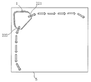
- a schematic diagram of the surrounding airflow transmitted from the air purification and ventilation device to the indoor space is shown, and the white arrow in the figure indicates the airflow.
- the perspective view which looked at the air purification and ventilation device from the left rear side direction is shown.
- the perspective view which looked at the air purifying and ventilation device from which the 1st end cap, the main exterior surface, and the 2nd connection surface was removed was seen from the front right side.
- cleaning and ventilation apparatus from which the 1st end cap, the main exterior surface, and the 2nd connection surface was removed was shown from the front side direction.
- the 1st valve plate is in the state which closes a communicating port
- the 2nd valve plate shows the composition schematic of the air distribution body in the state which opens the 2nd new air opening.
- a schematic configuration diagram of an airflow distributor in which the first valve plate is in a state of closing the first new air outlet and the second valve plate is in a state of closing the second new air outlet is shown.
- a schematic configuration diagram of an airflow distributor in which the first valve plate is located between the first new air outlet and the communication port and the second valve plate opens the second new air outlet is shown.
- a schematic configuration diagram of an airflow distributor in which the first valve plate is in a state of closing the first new air outlet and the second valve plate is in a state of opening the second new air outlet is shown.
- the 1st valve plate is in the state which closes a communication opening
- the 2nd valve plate shows the schematic diagram of composition of an air current distribution object in the state which closes the 2nd new wind mouth.
- the schematic diagram of a structure of the airflow distributor in another embodiment is shown.
- the configuration schematic diagram of the back plate on the case is shown.
- a schematic configuration diagram of a mounting plate and a hook is shown.
- the structural schematic diagram which attached the back plate to the hook of a mounting plate is shown.
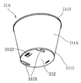
- a schematic diagram of the three-dimensional structure of the air filter viewed from near the first end of the filter cartridge in the modified example is shown.
- a schematic diagram of the three-dimensional structure of the air filter viewed from near the second end of the filter cartridge in the modified example is shown.
- FIG. 9 is a structural schematic view in which an air flow distributor, an air filter, a casing of a blower chamber, and a blower fan are mounted together in a modified example.
- the cross-sectional schematic diagram of an air intake means and a flow guide in a modification is shown.
- the structural schematic diagram of an air intake means and a flow guide in a modification is shown.
- FIG. 8 is a schematic view of the three-dimensional structure of the intake means and the flow guide in the modification.
- the schematic diagram of the airflow simulation at the suction port in the modified example is shown, and the arrow in the figure represents the airflow.
- FIG. 1a shows a front view of the air purification and ventilation device as viewed from the front direction.
- the direction outward which is perpendicular to the plane of the drawing, is the front direction
- the main exterior surface 131 is located on the front side surface of the cover body 13.
- the first end cap 11 is located at the upper end of the cover body 13 and the inward direction that is perpendicular to the paper surface of the drawing is the backward direction and the direction that is upward along the paper surface of the drawing is the upward direction.
- the second end cap 12 is located at the lower end of the cover body 13 with the downward direction along the paper surface of the drawing as the downward direction.
- the direction toward the right along the paper surface of the drawing is the right direction, and the first connecting surface 132 is connected to the right side of the main exterior surface 131.
- the direction toward the left along the paper surface of the drawing is the left direction, and the second connecting surface 133 is connected to the left side of the main exterior surface 131.
- the air purification and ventilation device has a case 1 having a columnar structure.
- the case 1 includes a cylindrical cover body 13.
- the first end cap 11 is attached to the upper end of the cover body 13.
- the second end cap 12 is attached to the lower end of the cover body 13.
- the front side surface of the cover body 13 is a main exterior surface 131.
- the right side of the main exterior surface 131 is connected to the first connection surface 132.
- the left side of the main exterior surface 131 is connected to the second connection surface 133.
- a display panel 139 for displaying control information is further attached to the main exterior surface 131.
- the air purification and ventilation device includes an intake chamber 22, an air purification chamber 23, an air flow distribution chamber 24, and an exhaust chamber 25. Both the intake chamber 22 and the air flow distribution chamber 24 communicate with the air purification chamber 23.
- the intake chamber 22 is provided with an intake fan 31.
- An air purification assembly 32 is provided in the air purification chamber 23.
- An exhaust fan 33 is provided in the exhaust chamber 25.
- the intake chamber 22 has blower ports 221/222 for communicating with the indoor space.
- the airflow distribution chamber 24 has a new air outlet 2411/2412 for communicating with the outdoor space and a suction port 2421/2422 for communicating with the indoor space.
- the air purification and ventilation device can realize the following three basic operation patterns.
- the first basic operation pattern is the new wind introduction operation pattern, which takes in fresh air from the outdoor space, purifies it, and then sends it to the indoor space. Air enters the airflow distribution chamber 24 through the fresh air outlets 2411/2412 and then flows into the air purification chamber 23. The intake chamber 22 takes in the purified air from the air purification chamber 23 and sends it to the indoor space from the air outlet 221/222.
- the second basic operation pattern is the internal circulation operation pattern, which takes in turbid air from the indoor space, purifies it, and then sends it to the indoor space. Air enters the airflow distribution chamber 24 through the suction ports 2421/2422 and then flows into the air purification chamber 23.
- the intake chamber 22 takes in the purified air from the air purifying chamber 23 and sends it to the indoor space from the blower ports 221/222.
- the third basic operation pattern is an operation pattern in which new wind is introduced and internal circulation is performed at the same time.
- Fresh air is taken in from the outdoor space, purified, and then sent to the indoor space, and at the same time, it becomes turbid from the indoor space.
- Intake air purify it, and send it to the indoor space.
- the outdoor air flows into the air purification chamber 23 after entering the airflow distribution chamber 24 from the fresh air outlet 2411/2412.
- the indoor air enters the air flow distribution chamber 24 from the suction port 2421/2422 and then flows to the air purification chamber 23 in the same manner.
- the intake chamber 22 takes in the purified air from the air purifying chamber 23 and sends it to the indoor space from the blower ports 221/222.
- the air purification and ventilation device can realize the exhaust operation pattern.
- the exhaust chamber 25 has a return air port 251 for communicating with the indoor space and an exhaust port 252a / 252b for communicating with the outdoor space.
- the exhaust fan 33 rotates, air enters the exhaust chamber 25 through the return air port 251, and is then exhausted to the outdoor space through the exhaust ports 252a/252b.
- Each of the above three basic operation patterns can be performed individually.
- the exhaust operation pattern can be performed individually. Further, the exhaust operation pattern can be performed at the same time as any one of the above three basic operation patterns.
- the exhaust chamber 25 is installed individually.
- the exhaust chamber 25 does not communicate with the air flow distribution chamber 24, the air purification chamber 23, or the intake chamber 22.
- the air purification and ventilation device when the exhaust work is performed, the exhaust airflow collides with the airflow in the airflow distribution chamber 24, the air purification chamber 23 or the intake chamber 22, and the airflow is turbulent or turbulent. None. It does not interfere with the normal operation of the internal circulation operation pattern and the new wind introduction operation pattern.
- the air purification and ventilation device When using the air purification and ventilation device, install the air purification and ventilation device indoors, and communicate the new air outlet 2411/2412 and the exhaust port 252a / 252b to the outdoor space.
- a new wind introduction operation pattern, an internal circulation operation pattern, an operation pattern in which new wind introduction and internal circulation are performed at the same time, and a single exhaust operation pattern, or an exhaust operation pattern and any one of the above operations A combination with a pattern can be realized.
- the exhaust airflow paths are individually provided, there is no possibility that airflow turbulence or turbulence will occur due to collision with other airflow paths.
- the various operating patterns of the air purification and ventilation device can be matched and combined so that the indoor air can be treated effectively and the quality of the indoor air can be improved.
- the air purification and ventilation device has a compact structure, is reasonably arranged, and has a small volume.
- the air purification and ventilation device has a columnar structure as a whole.
- the case 1 may have a structure in which one end is thick and the other end is thin, or the middle is thick and both ends are thin, and for example, a structure such as a cylinder or a prism may be used.
- the specific structure of the case 1 is determined according to the dimensions and shape of the contained parts and the actual needs.
- the intake chamber 22, the air purification chamber 23, the air flow distribution chamber 24, and the exhaust chamber 25 are all provided in the case 1 and the case 1 Are sequentially distributed from the first end to the second end.
- the overall columnar structure is easy to install and can be better integrated with the interior space.
- the air purification assembly 32 is a cylindrical filter network as a preferred embodiment in order to adapt to the structural arrangement of the air purification and ventilation system.
- the outer structure of the air purification assembly 32 can be better matched with the air purification chamber 23, and the space utilization rate is increased.
- the filter network may be distributed in layers above and below. According to the air purification chamber 23, compression of air and acceleration of the air flow velocity are realized, and it becomes easier for the air flow to enter the intake fan 31.
- a filter mesh is mounted within the air purification chamber to form an airflow passage. The airflow uniformly flows into the filter mesh of the air purification assembly 32.
- the area utilization rate of the filter network is improved and the purification efficiency is also improved.
- the filter mesh may be provided with any one or a combination of modules of an initial effect filter mesh module, a PM2.5 filtration module, and an activated carbon filtration module. It is also possible to remove harmful gaseous substances in the air in the indoor space or the outdoor space by arranging some reactive substances capable of removing other pollutants such as formaldehyde in the filter mesh.
- one end of the air purification chamber 23 communicates with the intake chamber 22 and the other end of the air purification chamber 23 communicates with the air flow distribution chamber 24.
- the structure of such a layout is compact and can reduce the volume of air purification and ventilation equipment.
- the upper end of the air purification chamber 23 is communicated with the intake chamber 22, and the lower end of the air purification chamber 23 is communicated with the air flow distribution chamber 24. Can be done.
- the air in the airflow distribution chamber 24 flows into the air purification chamber 23, is purified by the purification device, and then flows into the intake chamber 22.
- case 1 includes, for example, an electrostatic dust collection module, a streamer energy module, an electric supplementary heat module, and the like, for example, a filter net accommodation chamber and an air flow distribution.
- the first end of the case 1 has a storage chamber for accommodating the electric elements. 21 is further provided.
- the accommodation chamber 21 may be provided with other electrical control elements such as a power supply and a controller. Since the housing chamber 21 housing the electric control element is close to the display panel 139, wiring and communication from the housing chamber 21 to the display panel 139 are easy.
- the return air port 251 is provided on the end face of the second end of the case 1. That is, the return air port 251 is provided on the end surface of the second end cap 12.
- the indoor air enters the exhaust chamber 25 from the end surface of the second end cap 12 and is exhausted into the indoor space from the exhaust ports 252a/252b.
- the new air outlet 2411/2412 and the suction port 2421/2422 are exposed from the side wall of the case 1 in the airflow distribution chamber 24.
- the air outlet 221/222 is exposed from the side wall of the case 1 in the intake chamber 22.
- the air in the outdoor space When a new wind is introduced from the outdoor space to the indoor space, the air in the outdoor space enters the air flow distribution chamber 24 from the new air outlet 2411/2412, then flows upward into the air purification chamber 23, and is purified by the air purification assembly 32. Further, it enters the intake chamber 22 upward, and finally enters the indoor space from the air outlet 221/222 on the side wall of the case 1.
- the air in the indoor space When it is necessary to internally circulate and purify the air in the indoor space, the air in the indoor space enters the air flow distribution chamber 24 from the suction port 2421/2422 and then flows upward into the air purification chamber 23 to purify the air purification assembly 32.
- the air After being purified by, the air further enters the intake chamber 22 upward, and finally returns to the indoor space from the blower ports 221/222 on the side wall of the case 1.
- the exhaust ports 252a/252b are exposed from the side wall of the case 1 in the exhaust chamber 25.
- the return air port 251 is provided on the end surface of the second end cap 12.
- the airflow distribution chamber 24 can introduce the air entering from the new air outlet 2411/2412 into the air purification chamber 23. Further, the air entering from the suction port 2421/2422 can be introduced into the air purification chamber 23.
- the case 1 is provided with an air flow distributor 14.
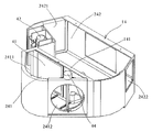
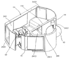
- the airflow distribution chamber 24 is provided in the airflow distribution body 14. As shown in FIGS. 3a, 3b, 3c, 3d, and 3e, the airflow distribution chamber 24 includes a new wind partition chamber 241 and a suction partition chamber 242. A partition wall 141 is provided between the fresh air partition chamber 241 and the suction partition chamber 242.
- the new wind partition chamber 241 communicates with the air purification chamber 23.
- the partition wall 141 is provided with a communication port 2413.
- the fresh air partition chamber 241 and the suction partition chamber 242 are connected by a communication port 2413.
- the new wind port 2411/2412 is provided on the side wall of the new wind partition chamber 241.
- the suction ports 2421/2422 are provided on the side wall of the suction partition chamber 242.
- the upper end of the new wind partition chamber 241 communicates with the air purification chamber 23.
- the upper end of the suction partition chamber 242 does not communicate with the air purification chamber 23. Air entering the fresh air partition chamber 241 from the fresh air outlets 2411/2412 can enter the air purification chamber 23 directly.
- the air that enters the suction partition chamber 242 from the suction ports 2421/2422 can enter the fresh air partition chamber 241 through the communication port 2413 and then enter the air purification chamber 23.
- Two new air vents are provided on the side wall of the new wind partition chamber 241 as shown in FIGS. 3a, 3b, 3d, and 3e to control the air to enter the airflow distribution chamber 24. There is.
- One of the new air outlets is the first new air outlet 2411, and the other new air outlet is the second new air outlet 2412.
- the first fresh air outlet 2411 is provided with a first valve plate 41.
- the first valve plate 41 is driven by the first drive mechanism 42, and is in a state where the first new air outlet 2411 is closed, a state in which the communication port 2413 is closed, and between the first new air port 2411 and the communication port 2413. Can be moved to each of the states.
- a second valve plate 43 is provided at the second fresh air outlet 2412.
- the second valve plate 43 is driven by the second drive mechanism 44 to close or open the second new air vent 2412.
- Both the first drive mechanism 42 and the second drive mechanism 44 may be rotary motors.
- the control device controls the rotation angle of the rotation shaft of the rotary motor to control the opening degree of the first valve plate 41 or the second valve plate, thereby controlling the magnitude of the air flow rate. ..
- the communication port 2413 includes a first communication port 2413a and a second communication port 2413b provided on the partition wall.
- the first valve plate 41 is driven by the first drive mechanism 42 to close the first new air outlet 2411, the first communication port 2413a, and the first new air outlet 2411 and the first. It is possible to move to each of the states located between the communication ports 2413a.
- the second valve plate 43 is driven by the second drive mechanism 44 to close the second new air outlet 2412, the second communication port 2413b, and the second new air outlet 2412 and the second. It is possible to move to each of the states located between the communication ports 2413b.
- the first communication port 2413a approaches the first valve plate 41 side
- the second communication port 2413b approaches the second valve plate 43 side. Since the structures on both the left and right sides of the airflow distributor 14 are basically symmetrical, it is easy to manufacture and install. Moreover, since both the first valve plate 41 and the second valve plate 43 rotate and move inside the fresh air partition chamber, they do not project from the outer wall of the airflow distributor. Therefore, the first valve plate 41 and the second valve plate 43 do not interfere with parts or walls outside the airflow distributor. Further, since the movement form of the first valve plate 41 and the second valve plate 43 is the same, when the second new air port 2412 is closed and fresh air is taken in through the first new air port 2411.
- the control logic for the operation pattern in which the fresh air introduction and the internal circulation are performed at the same time is similar, and such a control method is simpler and less likely to cause confusion during use by the user.
- an outdoor PM2.5 detection sensor is installed in the new wind partition chamber 241 and an indoor PM2.5 detection sensor is installed in the suction partition chamber 242. can do. Both the outdoor PM2.5 detection sensor and the indoor PM2.5 detection sensor are connected to the control device.
- the control device moves the movements of the first drive mechanism 42, the second drive mechanism 44, the intake fan, and the exhaust fan 33 based on the data detected by the outdoor PM2.5 detection sensor and the indoor PM2.5 detection sensor. It can be controlled to regulate the room air.
- the first connecting surface 132 and the second connecting surface 133 on both sides of the main exterior surface 131 are used to make the airflow sent from the air outlet 221/222 in the air purification and ventilation device uniform.
- Each of the above is provided with one air outlet.
- the blower port on the first connection surface 132 is the first blower port 221.
- the air outlet on the second connection surface 133 is the second air outlet 222. Both the first blower opening 221 and the second blower opening 222 blow air into the indoor space.
- a turbo fan may be used as the intake fan 31 so that the airflow sent from the first air blower 221 and the second air blower 222 forms a surrounding airflow. As shown in FIG.
- the airflow sent from the first air outlet 221 flows to one wall, and the airflow sent from the second air outlet 222 flows to the other vertical wall, and two flows. Are merged and surrounded from the opposite direction along the wall. Due to such a flow of fluid, the air flow is more evenly distributed throughout the room and is not blown out to the human body, so that the comfort of the human body is significantly improved.
- the side wall of the case 1 is provided with a first mounting surface 135 and a second mounting surface 136.
- the first fresh air outlet 2411 is exposed from the first mounting surface 135.
- the second fresh air outlet 2412 is exposed from the second mounting surface 136.
- One exhaust port is provided on each of the first mounting surface 135 and the second mounting surface 136.
- the exhaust port on the first mounting surface 135 is the first exhaust port 252a.
- the exhaust port on the second mounting surface 136 is the second exhaust port 252b.
- a first mounting interface 137 and a second mounting interface 138 are provided on each of the first mounting surface 135 and the second mounting surface 136. Then, the first mounting interface 137 or the second mounting interface 138 can be selected to mount the air purification and ventilation device on the wall of the room.
- the first fresh air outlet 2411 faces the wall when the air purification and ventilation device is attached by the first attachment interface 137.
- a channel communicating with the first fresh air outlet 2411 can be opened on the wall. It is also possible to block the first fresh air outlet 2411 and communicate with the outdoor space by the second fresh air outlet 2412.
- the second fresh air outlet 2412 faces the wall when the air purification and ventilation device is mounted by the second mounting interface 138.
- a channel communicating with the second fresh air outlet 2412 can be opened in the wall.
- the air purification and ventilation device may be mounted horizontally or vertically. When mounted vertically, the first end of the case may face down or face up, depending on the requirements of the interior layout.
- a back plate 7 is connected to the case 1 of the indoor air treatment device.
- a mounting hole 71 is provided in the back plate 7.
- a mounting plate 6 is fixedly connected to the wall 5.
- a hook 61 is fixed to the mounting plate 6.
- the back plate 7 is hooked on the hook 61 by the mounting hole 71. This makes it easier to hook the indoor air treatment device on the wall 5.
- the back plate 7, the mounting plate 6, and the hook 61 may be made of a sheet metal material. A connection by bolt connection or soldering may be adopted between the hook 61 and the mounting plate 6.
- two suction ports are provided on the side wall of the suction partition chamber 242.
- One of the suction ports is the first suction port 2421.
- the first suction port 2421 is exposed to the first connection surface 132.
- the other suction port is the second suction port 2422.
- the second suction port 2422 is exposed on the second connection surface 133.
- a window grid 134 is further provided on the first connecting surface 132 and the second connecting surface 133. Then, the airflow entering the first suction port 2421 and the second suction port 2422 and the airflow flowing out from the first air outlet 221 and the second air outlet 222 become uniform.
- (A) First mounting method The air purifying and ventilating device is mounted on the wall 5 by the first mounting surface 135, and the first fresh air outlet 2411 and the first exhaust outlet 252a are attached to the wall so that the outdoor space can be removed. It is in a blocked state.
- the first valve plate 41 and the second valve plate 43 are controlled by the following methods, respectively.
- the first valve plate 41 moves to open the communication port 2413.
- the communication port 2413 connects the fresh air partition chamber 241 and the suction partition chamber 242.
- the second valve plate 43 moves to a state in which the second new air outlet 2412 is opened.
- the second new air outlet 2412 communicates with the outdoor space.
- the exhaust operation pattern will be described.
- the indoor space and the outdoor space are communicated with each other through the return air port 251 and the second exhaust port 252b.
- the exhaust fan 33 may be started directly.
- the exhaust operation pattern can be performed individually or at the same time as the above three operation patterns.
- the second mounting surface 136 mounts the air cleaning and ventilation device on the wall.
- the second new air port 2412 and the second exhaust port 252b are attached to the wall and are in a state of being shielded from the outdoor space.
- the first valve plate 41 and the second valve plate 43 are controlled by the following methods, respectively.
- the new wind introduction operation pattern will be described with reference to FIG. 3e.
- the 1st valve plate 41 moves to the state which closes the communicating port 2413, and the 1st fresh air outlet 2411 communicates with an outdoor space.
- the intake fan 31 rotates, fresh air in the outdoor space passes through the first fresh air outlet 2411 and the fresh air partition chamber 241 in order, enters the air purification chamber 23, and is purified by the air purification assembly 32, and then the intake chamber 22. Then, the air is blown into the indoor space through the blower ports 221/222 in order.
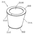
- the side wall of the filter cartridge 211A facing the windward space S24 is the windward surface 2115.
- the side wall of the filter cartridge 211A toward the leeward space S25 is the leeward lower surface 2116.
- the wind surface 2115 is directed in the direction in which the airflow enters. Since the distance of the wind surface 2115 to the position where the air flow enters is the shortest, most of the air flow enters the inner chamber 2111 of the filter cartridge 211A from the wind surface 2115.
- the second end 2113 of the filter cartridge 211A is inclined toward the upwind space S24.
- the edge of the second end 2113 of the filter cartridge 211A includes an upwind arc 2113a close to the upwind space S24 and a leeward arc 2113b close to the leeward space S25.
- the boundary points between the upwind arc 2113a and the downwind arc 2113b are points C and D.
- the midpoint of the windward arc 2113a is point B.
- the midpoint of the leeward arc 2113b is point A.
- the point O in FIG. 6a is the center of the first end 2112 of the filter cartridge 211A.
- the central axis 2112c of the first end 2112 of the filter cartridge 211A passes through the point O.
- the distance between the midpoint A of the leeward arc 2113b and the central axis 2112c of the first end 2112 of the filter cartridge 211A is d1.
- the distance between the midpoint B of the upwind arc 2113a and the central axis 2112c of the first end 2112 of the filter cartridge 211A is d2.
- the connecting line between the center O of the first end 2112 and the center O'of the second end 2113 of the filter cartridge 211A is OO'.
- the tie line OO′ lies in the plane of the plane of the diameter EF of the first end 2112 and the diameter CD of the second end 2113 of the filter cartridge 211A.
- an intake means 13A having an intake port 1311 for intake of air shown in FIGS. 7a, 7b, and 7c is adopted. May be good.
- the suction port 1311 is provided with a flow guide cover 12A as a cover.
- a plurality of flow guiding holes 1221 are provided in the flow guiding cover 12A.
- An airflow passage 15 is formed between the flow guide cover 12A and the intake means 13A.
- a flow guide cover 12A is provided as a cover at the suction port 1311 of the intake means 13A.
- a plurality of flow guiding holes 1221 are provided in the flow guiding cover 12A.
- An air flow passage 15 is formed between the flow guide cover 12A and the intake means 13A.
- the airflow in the room becomes uniform, and the comfort of use by the user is improved. Further, since the flow guide cover 12A is covered by the suction port 1311, the user cannot directly observe the internal structure of the indoor air treatment device from the suction port 1311, which improves the aesthetic appearance of the product and also causes noise. It will be reduced.
- the air purification and ventilation device described above has various industrial deficiencies existing in the prior art, and thus has high industrial utility value.
Landscapes
- Engineering & Computer Science (AREA)
- Chemical & Material Sciences (AREA)
- Combustion & Propulsion (AREA)
- Mechanical Engineering (AREA)
- General Engineering & Computer Science (AREA)
- Filtering Of Dispersed Particles In Gases (AREA)
Priority Applications (1)
| Application Number | Priority Date | Filing Date | Title |
|---|---|---|---|
| JP2021504054A JP7219409B2 (ja) | 2019-03-01 | 2020-02-28 | 空気浄化及び通風装置 |
Applications Claiming Priority (6)
| Application Number | Priority Date | Filing Date | Title |
|---|---|---|---|
| CN201910157084.2 | 2019-03-01 | ||
| CN201910157084.2A CN111637550B (zh) | 2019-03-01 | 2019-03-01 | 空气净化及通风装置 |
| CN201910157078.7 | 2019-03-01 | ||
| CN201910157078.7A CN111637549B (zh) | 2019-03-01 | 2019-03-01 | 室内空气处理装置 |
| CN201910472594.9 | 2019-05-31 | ||
| CN201910472594.9A CN112007451B (zh) | 2019-05-31 | 2019-05-31 | 一种空气净化装置 |
Publications (1)
| Publication Number | Publication Date |
|---|---|
| WO2020179687A1 true WO2020179687A1 (ja) | 2020-09-10 |
Family
ID=72337826
Family Applications (1)
| Application Number | Title | Priority Date | Filing Date |
|---|---|---|---|
| PCT/JP2020/008391 Ceased WO2020179687A1 (ja) | 2019-03-01 | 2020-02-28 | 空気浄化及び通風装置 |
Country Status (2)
| Country | Link |
|---|---|
| JP (1) | JP7219409B2 (https=) |
| WO (1) | WO2020179687A1 (https=) |
Cited By (6)
| Publication number | Priority date | Publication date | Assignee | Title |
|---|---|---|---|---|
| CN114522499A (zh) * | 2022-03-10 | 2022-05-24 | 永隆装饰工程有限公司 | 一种建筑装饰用空气净化装置 |
| CN114659144A (zh) * | 2020-12-22 | 2022-06-24 | 芜湖美的厨卫电器制造有限公司 | 吸油烟机 |
| CN115095943A (zh) * | 2022-05-31 | 2022-09-23 | 上海伯涵热能科技有限公司 | 一种双向流全屋新风系统 |
| WO2023065681A1 (zh) * | 2021-10-20 | 2023-04-27 | 青岛海尔空调器有限总公司 | 空调室内机 |
| WO2023065680A1 (zh) * | 2021-10-20 | 2023-04-27 | 青岛海尔空调器有限总公司 | 空调室内机 |
| CN116465812A (zh) * | 2023-04-25 | 2023-07-21 | 中认诺也(江苏)检验认证有限公司 | 吸尘器滤芯拦截率检测方法 |
Families Citing this family (1)
| Publication number | Priority date | Publication date | Assignee | Title |
|---|---|---|---|---|
| CN113048564A (zh) * | 2021-03-22 | 2021-06-29 | 珠海格力电器股份有限公司 | 室内机和空调器 |
Citations (4)
| Publication number | Priority date | Publication date | Assignee | Title |
|---|---|---|---|---|
| JP2001248865A (ja) * | 2000-03-08 | 2001-09-14 | Midori Anzen Co Ltd | 換気機能付空気清浄装置 |
| JP2010043854A (ja) * | 2009-09-29 | 2010-02-25 | Max Co Ltd | 空気清浄機 |
| WO2013153995A1 (ja) * | 2012-04-09 | 2013-10-17 | バルミューダ株式会社 | 空気清浄装置 |
| JP2018179490A (ja) * | 2017-04-11 | 2018-11-15 | 大連理工大学Dalian University of Technology | 空気清浄機能を備えた窓及びその換気方法 |
-
2020
- 2020-02-28 WO PCT/JP2020/008391 patent/WO2020179687A1/ja not_active Ceased
- 2020-02-28 JP JP2021504054A patent/JP7219409B2/ja active Active
Patent Citations (4)
| Publication number | Priority date | Publication date | Assignee | Title |
|---|---|---|---|---|
| JP2001248865A (ja) * | 2000-03-08 | 2001-09-14 | Midori Anzen Co Ltd | 換気機能付空気清浄装置 |
| JP2010043854A (ja) * | 2009-09-29 | 2010-02-25 | Max Co Ltd | 空気清浄機 |
| WO2013153995A1 (ja) * | 2012-04-09 | 2013-10-17 | バルミューダ株式会社 | 空気清浄装置 |
| JP2018179490A (ja) * | 2017-04-11 | 2018-11-15 | 大連理工大学Dalian University of Technology | 空気清浄機能を備えた窓及びその換気方法 |
Cited By (8)
| Publication number | Priority date | Publication date | Assignee | Title |
|---|---|---|---|---|
| CN114659144A (zh) * | 2020-12-22 | 2022-06-24 | 芜湖美的厨卫电器制造有限公司 | 吸油烟机 |
| WO2023065681A1 (zh) * | 2021-10-20 | 2023-04-27 | 青岛海尔空调器有限总公司 | 空调室内机 |
| WO2023065680A1 (zh) * | 2021-10-20 | 2023-04-27 | 青岛海尔空调器有限总公司 | 空调室内机 |
| CN114522499A (zh) * | 2022-03-10 | 2022-05-24 | 永隆装饰工程有限公司 | 一种建筑装饰用空气净化装置 |
| CN114522499B (zh) * | 2022-03-10 | 2024-03-15 | 永隆装饰工程有限公司 | 一种建筑装饰用空气净化装置 |
| CN115095943A (zh) * | 2022-05-31 | 2022-09-23 | 上海伯涵热能科技有限公司 | 一种双向流全屋新风系统 |
| CN116465812A (zh) * | 2023-04-25 | 2023-07-21 | 中认诺也(江苏)检验认证有限公司 | 吸尘器滤芯拦截率检测方法 |
| CN116465812B (zh) * | 2023-04-25 | 2024-05-14 | 中认诺也(江苏)检验认证有限公司 | 吸尘器滤芯拦截率检测方法 |
Also Published As
| Publication number | Publication date |
|---|---|
| JPWO2020179687A1 (https=) | 2020-09-10 |
| JP7219409B2 (ja) | 2023-02-08 |
Similar Documents
| Publication | Publication Date | Title |
|---|---|---|
| JP7219409B2 (ja) | 空気浄化及び通風装置 | |
| JP7174296B2 (ja) | 室内空気処理装置及びその作動方法 | |
| CN105115040B (zh) | 自循环新风换气机及其控制方法 | |
| CN107676870A (zh) | 立式空调室内机和具有其的空调器 | |
| CN107062391A (zh) | 一种具有空气净化功能的空调器 | |
| CN205747062U (zh) | 一种防止油烟逃逸的风幕系统 | |
| CN112747380A (zh) | 空调器、空气净化装置及其控制方法 | |
| CN209341504U (zh) | 一种家用新风净化一体机 | |
| CN206430312U (zh) | 新风净化器及空气净化装置 | |
| CN111637548B (zh) | 室内空气处理装置及其工作方法 | |
| CN205980056U (zh) | 一种新风机和空气净化机一体机 | |
| CN214249814U (zh) | 空气净化装置、室内机组件及空调器 | |
| CN210373770U (zh) | 空气净化模块、空调室内机和空调器 | |
| CN211177135U (zh) | 空调室内机 | |
| CN204084546U (zh) | 立体交换式室内加热器 | |
| CN107449053A (zh) | 一种吊顶式空调器室内机 | |
| CN206094338U (zh) | 空调一体机 | |
| CN207847994U (zh) | 模块化新风机 | |
| CN206310637U (zh) | 一种高效新风机 | |
| CN207113053U (zh) | 智能空气净化器 | |
| CN212274192U (zh) | 一种室内通风装置 | |
| CN211222966U (zh) | 车用双腔式自清洁空气净化器 | |
| CN116221888A (zh) | 空气处理器及其控制方法 | |
| CN111637550B (zh) | 空气净化及通风装置 | |
| CN108458426A (zh) | 高效过滤吊顶式新风机 |
Legal Events
| Date | Code | Title | Description |
|---|---|---|---|
| 121 | Ep: the epo has been informed by wipo that ep was designated in this application |
Ref document number: 20765491 Country of ref document: EP Kind code of ref document: A1 |
|
| ENP | Entry into the national phase |
Ref document number: 2021504054 Country of ref document: JP Kind code of ref document: A |
|
| NENP | Non-entry into the national phase |
Ref country code: DE |
|
| 122 | Ep: pct application non-entry in european phase |
Ref document number: 20765491 Country of ref document: EP Kind code of ref document: A1 |