WO2020179430A1 - シールド構造、及びワイヤーハーネス - Google Patents
シールド構造、及びワイヤーハーネス Download PDFInfo
- Publication number
- WO2020179430A1 WO2020179430A1 PCT/JP2020/006187 JP2020006187W WO2020179430A1 WO 2020179430 A1 WO2020179430 A1 WO 2020179430A1 JP 2020006187 W JP2020006187 W JP 2020006187W WO 2020179430 A1 WO2020179430 A1 WO 2020179430A1
- Authority
- WO
- WIPO (PCT)
- Prior art keywords
- side wall
- electric wires
- wall portions
- parallel
- shield member
- Prior art date
- Legal status (The legal status is an assumption and is not a legal conclusion. Google has not performed a legal analysis and makes no representation as to the accuracy of the status listed.)
- Ceased
Links
Images


Classifications
-
- H—ELECTRICITY
- H01—ELECTRIC ELEMENTS
- H01R—ELECTRICALLY-CONDUCTIVE CONNECTIONS; STRUCTURAL ASSOCIATIONS OF A PLURALITY OF MUTUALLY-INSULATED ELECTRICAL CONNECTING ELEMENTS; COUPLING DEVICES; CURRENT COLLECTORS
- H01R13/00—Details of coupling devices of the kinds covered by groups H01R12/70 or H01R24/00 - H01R33/00
- H01R13/648—Protective earth or shield arrangements on coupling devices, e.g. anti-static shielding
- H01R13/658—High frequency shielding arrangements, e.g. against EMI [Electro-Magnetic Interference] or EMP [Electro-Magnetic Pulse]
- H01R13/6591—Specific features or arrangements of connection of shield to conductive members
- H01R13/65912—Specific features or arrangements of connection of shield to conductive members for shielded multiconductor cable
- H01R13/65915—Twisted pair of conductors surrounded by shield
-
- H—ELECTRICITY
- H01—ELECTRIC ELEMENTS
- H01B—CABLES; CONDUCTORS; INSULATORS; SELECTION OF MATERIALS FOR THEIR CONDUCTIVE, INSULATING OR DIELECTRIC PROPERTIES
- H01B7/00—Insulated conductors or cables characterised by their form
- H01B7/0045—Cable-harnesses
-
- H—ELECTRICITY
- H01—ELECTRIC ELEMENTS
- H01R—ELECTRICALLY-CONDUCTIVE CONNECTIONS; STRUCTURAL ASSOCIATIONS OF A PLURALITY OF MUTUALLY-INSULATED ELECTRICAL CONNECTING ELEMENTS; COUPLING DEVICES; CURRENT COLLECTORS
- H01R13/00—Details of coupling devices of the kinds covered by groups H01R12/70 or H01R24/00 - H01R33/00
- H01R13/648—Protective earth or shield arrangements on coupling devices, e.g. anti-static shielding
- H01R13/658—High frequency shielding arrangements, e.g. against EMI [Electro-Magnetic Interference] or EMP [Electro-Magnetic Pulse]
- H01R13/6581—Shield structure
-
- H—ELECTRICITY
- H01—ELECTRIC ELEMENTS
- H01R—ELECTRICALLY-CONDUCTIVE CONNECTIONS; STRUCTURAL ASSOCIATIONS OF A PLURALITY OF MUTUALLY-INSULATED ELECTRICAL CONNECTING ELEMENTS; COUPLING DEVICES; CURRENT COLLECTORS
- H01R13/00—Details of coupling devices of the kinds covered by groups H01R12/70 or H01R24/00 - H01R33/00
- H01R13/648—Protective earth or shield arrangements on coupling devices, e.g. anti-static shielding
- H01R13/658—High frequency shielding arrangements, e.g. against EMI [Electro-Magnetic Interference] or EMP [Electro-Magnetic Pulse]
- H01R13/6591—Specific features or arrangements of connection of shield to conductive members
-
- H—ELECTRICITY
- H01—ELECTRIC ELEMENTS
- H01R—ELECTRICALLY-CONDUCTIVE CONNECTIONS; STRUCTURAL ASSOCIATIONS OF A PLURALITY OF MUTUALLY-INSULATED ELECTRICAL CONNECTING ELEMENTS; COUPLING DEVICES; CURRENT COLLECTORS
- H01R2103/00—Two poles
Definitions
- This disclosure relates to a shield structure and a wire harness.
- the shield member covers two electric wires arranged side by side from the vertical direction and the horizontal direction, the structure tends to be complicated and it is difficult to reduce the weight.
- the present disclosure has been completed based on the above circumstances, and provides a shield structure and a wire harness in which at least one of structural simplification, weight reduction, and noise resistance performance improvement is solved. ..
- the shield structure of the present disclosure includes two electric wires twisted together, a twisted pair cable having a parallel portion in which the two electric wires are arranged, and two conductive side wall portions arranged around the parallel portion. And a shield member having two connecting portions for electrically connecting the two side wall portions, the two connecting portions being in the extending direction of the parallel portion of the two side wall portions. It is arranged at the front end and the rear end, respectively.
- the wire harness of the present disclosure is formed by twisting two electric wires together, and is connected to a twisted pair cable having a parallel portion in which the two electric wires are arranged, and ends of the two electric wires forming the parallel portion, respectively.
- a shield member having a connecting portion, and the two connecting portions are respectively arranged at a front end portion and a rear end portion of the two side wall portions in the extending direction of the parallel portion.
- At least one effect of simplification of the structure, weight reduction, and improvement of noise resistance performance can be obtained with respect to the technology related to the shield structure.
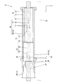
- FIG. 1 is a side view showing a wire harness according to the first embodiment.
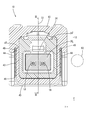
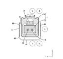
- FIG. 2 is a sectional view taken along line II-II in FIG.
- FIG. 3 is a sectional view taken along line III-III in FIG.
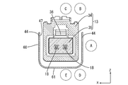
- FIG. 4 is a sectional view taken along line IV-IV in FIG.
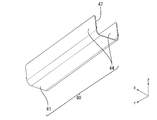
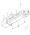
- FIG. 5 is a perspective view showing a wire harness.
- FIG. 6 is an exploded perspective view of the wire harness showing a state where the shield member is separated from the male connector.
- FIG. 7A is a schematic cross-sectional view showing the arrangement of electric wires in Calculation Example 1.
- FIG. 7B is a perspective view showing the shield member according to Calculation Example 1.
- FIG. 8 is a schematic cross-sectional view showing the arrangement of electric wires in Calculation Example 2.
- FIG. 7A is a schematic cross-sectional view showing the arrangement of electric wires in Calculation Example 1.
- FIG. 7B is a perspective view showing the shield member according to Calculation Example 1.
- FIG. 8 is
- FIG. 9 is a schematic cross-sectional view showing the arrangement of electric wires with respect to Calculation Example 3.
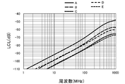
- FIG. 10 is a graph showing changes in LCL with respect to the frequency of the common mode in Calculation Examples 1 to 3.
- FIG. 11 is a graph showing the change in LCL with respect to the frequency of the common mode in Calculation Example 3.
- FIG. 12 is a graph showing changes in LCL with respect to the frequency of the common mode in the calculation example 2.
- FIG. 13 is a graph showing a change in LCL with respect to the frequency of the common mode in the calculation example 1.
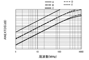
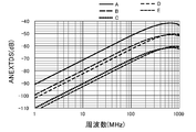
- FIG. 14 is a graph showing changes in ANEXTDS with respect to the frequency of the noise source for Calculation Examples 1 to 3.
- FIG. 15 is a graph showing changes in ANEXTDS with respect to the frequency of the noise source for Calculation Example 3.
- FIG. 16 is a graph showing changes in ANEXTDS with respect to the frequency of the noise source for Calculation Example 2.
- FIG. 17 is a graph showing changes in ANEXTDS with respect to the frequency of the noise source for Calculation Example 1.
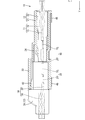
- FIG. 18 is a cross-sectional view showing a wire harness according to the second embodiment.
- FIG. 19 is a perspective view showing a wire harness according to the third embodiment.
- a shield member having two side wall parts and two connection parts electrically connecting the two side wall parts, wherein the two connection parts are of the parallel part of the two side wall parts. They are arranged at the front end and the rear end in the extending direction, respectively.
- the two electric wires arranged in the parallel portion are electromagnetically shielded from the noise source located around the side wall portion by the side wall portion arranged around the parallel portion.
- the noise resistance performance of the twisted pair cable can be improved.
- the structure of the shield member can be simplified. As a result, the weight of the shield member can be reduced. In addition, the manufacturing cost of the shield member can be reduced. Further, two electric wires constituting the parallel portion are exposed from this opening.
- the noise source is arranged in the area where the two electric wires forming the parallel portion are exposed, it is possible to suppress deterioration in the noise resistance performance of the twisted pair cable. The reason will be explained below.
- the noise source is arranged in the area where the two electric wires forming the parallel portion are exposed, the noise generated by the noise source affects both of the two electric wires. Since the noise given to both of the two electric wires is canceled in the differential communication cable, it is possible to prevent the noise resistance performance of the twisted pair cable from being deteriorated.
- the two side wall portions are formed in mirror symmetry with respect to an imaginary plane that includes an intermediate position of the two electric wires that form the parallel portion and that extends along a direction in which the two electric wires extend. It is preferable to have.
- the connecting portion is preferably formed integrally with the two side wall portions.
- the manufacturing cost of the shield member can be reduced.
- the two side wall portions are located around two terminals connected to respective ends of the two electric wires forming the parallel portion.
- a portion exposed from an end portion of a sheath that collectively surrounds the two electric wires is the parallel portion, and the connecting portion is provided at an end portion of the sheath. It is preferable to have an outer fitting portion that is fitted over and an extending portion that extends from the outer fitting portion and contacts the two side wall portions.
- the number of parts can be reduced. Thereby, the manufacturing cost of the shield structure can be reduced.
- a wire harness according to the present disclosure is a twisted pair cable having two parallel electric wires twisted together and having a parallel portion in which the two electric wires are arranged, and end portions of the two electric wires forming the parallel portion.
- a shield member having two connecting portions, and the two connecting portions are respectively arranged at a front end portion and a rear end portion of the two side wall portions in the extending direction of the parallel portion.
- the connector has a fixing portion to which the shield member is fixed.
- the structure of the wire harness can be simplified as compared with the case where the shield member is fixed to a member different from the connector.
- a wire harness 10 includes a first UTP (Unshielded Twisted Pair) cable 11 (an example of a twisted pair cable) and a male connector 12 (connector connected to an end of the first UTP cable 11).
- UTP Unshielded Twisted Pair
- a male connector 12 connector connected to an end of the first UTP cable 11.
- An example a female connector 13 (an example of a connector) fitted to the male connector 12, and a second UTP (Unshielded Twisted Pair) cable 14 (an example of a twisted pair cable) in which the female connector 13 is connected to an end portion.
- the electric wire 62 which is a noise source, is fixed to the wire harness 10 according to the present embodiment by a known method such as tape winding in a state of being arranged along the wire harness 10 (see FIG. 4).
- An example of the electric wire 62 that becomes a noise source is a power supply line connected to a device. Noise may be mixed into such a power line from a connected device.
- the Z direction is upward, the Y direction is forward, and the X direction is left.
- some of the same members may be denoted by reference numerals, and other members may not be denoted by reference numerals.
- the first UTP cable 11 is formed by collectively surrounding the outer circumference of two first electric wires 15 twisted together by an insulating first sheath 16.
- the first electric wire 15 has a known structure in which the outer circumference of a conductive core wire is covered with an insulating coating made of an insulating synthetic resin.
- the two first electric wires 15 are led out from the end of the first sheath 16.
- the two first electric wires 15 led out from the end portion of the first sheath 16 are untwisted, extend in the front-back direction (an example of the direction in which the two electric wires extend), and are spaced in the left-right direction. It is said to be the first parallel portion 17 (an example of the parallel portion) arranged side by side.
- the two first electric wires 15 of the first UTP cable 11 located inside the first sheath 16 are twisted together.
- the distance between the two first electric wires 15 forming the first parallel portion 17 in the left-right direction is the smallest near the end of the first sheath 16 and widens as the distance from the end of the first sheath 16 increases. ..
- Male terminals 18 are connected to the ends of the two first electric wires 15 constituting the first UTP cable 11. Thereby, two male terminals 18 are connected to one first UTP cable 11.
- the two male terminals 18 have the same shape and size.
- the male terminal 18 is formed by pressing a metal plate material into a predetermined shape.
- the male terminal 18 is fixed to the first electric wire 15 by crimping to the end of the first electric wire 15 and is electrically connected to the core wire of the first electric wire 15 to the electric wire connecting portion 19 and the electric wire connecting portion 19. It has a male tab 20 that extends forward in a row.
- the male connector 12 As shown in FIG. 3, the male connector 12 has a male outer housing 21 and a male inner housing 22 housed inside the male outer housing 21.
- the male outer housing 21 has a hood portion 23 that opens forward.
- the female connector 13 is fitted inside the hood portion 23.
- the male outer housing 21 is formed by injection molding an insulating synthetic resin. Inside the male outer housing 21, a male lance 24 extending forward is formed. The male lance 24 is elastically engaged with the male inner housing 22, so that the male inner housing 22 is held in the male outer housing 21 in a retaining state.
- the two male terminals 18 are arranged in the male inner housing 22 in a state where they are arranged side by side in the left-right direction.
- the male tab 20 of the male terminal 18 is arranged in the hood portion 23 so as to extend forward.
- the second UTP cable 14 is formed by collectively surrounding the outer circumference of two second electric wires 29 twisted together by an insulating second sheath 30.
- the two second electric wires 29 led out from the end of the second sheath 30 are untwisted and extend in the front-rear direction (an example of the direction in which the two electric wires extend) and are spaced in the left-right direction.
- the second parallel unit 31 (an example of the parallel unit) is arranged side by side.
- the distance between the two second electric wires 29 constituting the second parallel portion 31 in the left-right direction is the narrowest near the end of the second sheath 30, and widens as the distance from the end of the second sheath 30 increases. .. Since the configuration of the second UTP cable 14 is the same as that of the first UTP cable 11, duplicate description is omitted.
- Female terminals 32 are respectively connected to the ends of the two second electric wires 29 that form the second UTP cable 14. Thereby, the two female terminals 32 are connected to one second UTP cable 14.
- the two female terminals 32 have the same shape and size.
- the female terminal 32 is formed by pressing a metal plate material into a predetermined shape.
- the female terminal 32 is fixed to the second electric wire 29 by crimping to the end of the second electric wire 29, and is electrically connected to the core wire of the second electric wire 29 to the electric wire connecting portion 53 and the electric wire connecting portion 53. It has a connecting cylinder portion 33 that extends rearward in succession.
- the male tab 20 of the male terminal 18 can be inserted into the inside of the connection tubular portion 33.
- An elastically deformable elastic contact piece (not shown) is arranged inside the connection tubular portion 33. By the elastic contact piece elastically contacting the male tab 20, the female terminal 32 and the male terminal 18 are electrically connected.
- the rear half of the female connector 13 is adapted to be fitted into the hood portion 23 of the male connector 12 from the rear side. With the male connector 12 and the female connector 13 fitted together, the front half of the female connector 13 is located in front of the hood portion 23.
- the female connector 13 has a female outer housing 34 and a female inner housing 35 housed inside the female outer housing 34.
- the female outer housing 34 is formed by injection molding an insulating synthetic resin.
- a female lance 36 extending rearward is formed inside the female outer housing 34.
- the female lance 36 elastically engages with the female inner housing 35, so that the female inner housing 35 is retained in the female outer housing 34 in a retaining state.
- the female terminal 32 is held in the female inner housing 35.
- the two female terminals 32 are arranged in the female inner housing 35 so as to be arranged side by side in the left-right direction.
- the lock portion 42 formed in the female connector 13 is locked to the male connector 12, so that the female connector 13 is pulled out in the hood portion 23. It is designed to be held in a stopped state.
- the shield member 43 is formed by pressing a conductive metal plate material into a predetermined shape.
- a conductive metal plate material As the metal forming the shield member 43, any metal such as copper, copper alloy, aluminum, aluminum alloy, or the like can be appropriately selected.
- a plating layer made of metal may be formed on the surface of the shield member 43.
- any metal such as tin and nickel can be appropriately selected.
- the shield member 43 has two side wall portions 44, a front connecting portion 45 (an example of a connecting portion) and a rear connecting portion 46 (an example of a connecting portion) that connect the two side wall portions 44.
- the two side wall portions 44 have the same shape and size and are made of a rectangular metal plate material.
- the two side wall portions 44 are arranged in an upright posture such that their wall surfaces are parallel to each other.
- the term “parallel” includes a case where the wall surfaces of the two side wall portions 44 are parallel to each other, and a case where the wall surfaces are recognized to be substantially parallel even if not parallel.
- the lower edges of the front end portions of the two side wall portions 44 are connected by the front connecting portion 45, and the lower edges of the rear end portions of the two side wall portions 44 are connected by the rear connecting portion 46.
- the two side wall portions 44 are electrically connected by the front connecting portion 45 and the rear connecting portion 46.
- the upper edges of the two side walls 44 are upper openings 47 (an example of openings) that open upward.
- the upper surface of the shield member 43 is all open.
- a region surrounded by the lower edges of the two side walls 44, the rear edge of the front connecting portion 45, and the front edge of the rear connecting portion 46 is a lower opening 48 that opens downward.
- a fitting groove 49 (an example of a fixing portion) that opens downward is formed on the left side wall and the right side wall of the male outer housing 21.
- the side wall portion 44 is inserted into the fitting groove 49.
- the connecting portion of the shield member 43 is arranged along the lower surface of the lower wall of the male outer housing 21.
- the shield member 43 is fixed to the male connector 12 by any means such as press fitting, screwing, riveting, adhesion, fusion bonding, and a holding structure with lock claws.
- shield structure 50, 52 As shown in FIG. 2, the shield structure 50 of the male connector 12 is described.
- the two side wall portions 44 of the shield member 43 attached to the male connector 12 are arranged around the first parallel portion 17 of the first electric wire 15 constituting the first UTP cable 11 (position outside in the left-right direction). There is.
- the first parallel portion 17 of the first electric wire 15 constituting the first UTP cable 11 is electromagnetically shielded from the noise source located around the side wall portion 44.
- the two side wall portions 44 of the shield member 43 are arranged around the male terminal 18 connected to the end portion of the first electric wire 15 configuring the first UTP cable 11 (outward position in the left-right direction). .. Thereby, the male terminal 18 is electromagnetically shielded from the noise source located around the side wall portion 44.
- the first parallel portion 17 of the first electric wire 15 configuring the first UTP cable 11 and the male terminal 18 connected to the end portion of the first parallel portion 17 have two side wall portions in the front-back direction. It is located inside 44.
- the two side wall portions 44 are formed in mirror symmetry with respect to the virtual surface 51 that includes the intermediate positions of the two first electric wires 15 that form the first parallel portion 17 in the left-right direction and that extends in the front-rear direction. That is, the two side wall portions 44 are arranged symmetrically with respect to the virtual surface 51. Thereby, the electromagnetic environment of the first parallel portion 17 of the first electric wire 15 and the male terminal 18 is made uniform in the left-right direction.
- the first parallel portion 17 of the first electric wire 15 and the male terminal 18 are arranged near the center of the height dimension of the two side wall portions 44 in the vertical direction. As a result, the electromagnetic environment of the first parallel portion 17 of the first electric wire 15 and the male terminal 18 is made uniform in the vertical direction.
- the shield structure 52 of the female connector 13 will be explained.
- two side wall portions are provided around a portion of the female connector 13 located inside the hood portion 23 of the male connector 12 (a position outward in the left-right direction). 44 is located.
- the second parallel portion 31 of the second electric wire 29 that constitutes the second UTP cable 14 around the portion where the electric wire connecting portion 53 of the female terminal 32 is crimped (outward position in the left-right direction)
- Two side wall portions 44 are located.
- the second parallel portion 31 of the second electric wire 29 forming the second UTP cable 14 is electromagnetically shielded from the noise source located around the side wall portion 44.
- the two side wall portions 44 of the shield member 43 are arranged around the female terminal 32 connected to the end portion of the second electric wire 29 (position outside in the left-right direction). As a result, the female terminal 32 is electromagnetically shielded from a noise source located around the side wall portion 44.
- the portion of the second parallel portion 31 of the second electric wire 29 to which the wire connecting portion 53 of the female terminal 32 is crimped and the female terminal 32 connected to the end portion of the second parallel portion 31 are It is located inside the two side wall portions 44 in the front-rear direction.
- the distance between the two wires 29 is the same.
- the two side wall portions 44 are formed in mirror symmetry with respect to the virtual surface 51 including the intermediate position of the two second electric wires 29 forming the second parallel portion 31 in the left-right direction and extending in the front-rear direction. That is, the two side wall portions 44 are symmetrically arranged with respect to the virtual surface 51. Thereby, the electromagnetic environment of the second parallel portion 31 of the second electric wire 29 and the female terminal 32 is made uniform in the left-right direction.
- the second parallel portion 31 and the female terminal 32 of the second electric wire 29 are arranged near the center of the height dimension of the two side wall portions 44 in the vertical direction. Thereby, the electromagnetic environment of the second parallel portion 31 of the second electric wire 29 and the female terminal 32 is made uniform in the vertical direction.
- the first sheath 16 is peeled off at the end of the first UTP cable 11. As a result, the two first electric wires 15 are exposed from the end portion of the first sheath 16. The two exposed first wires 15 are untwisted. A male terminal 18 is connected to each of the ends of each first electric wire 15.
- the female terminal 32 is connected to each end of each second electric wire 29.
- the male terminal 18 is housed in the male inner housing 22.
- the male inner housing 22 is assembled from the rear of the male outer housing 21.
- the male inner housing 22 and the male outer housing 21 are integrally assembled by locking the male lance 24 of the male outer housing 21 to the male inner housing 22 from the rear side.
- Shield member 43 is formed by pressing a metal plate material.
- the two side wall portions 44 of the shield member 43 are inserted into the fitting groove 49 of the male outer housing 21 from below.
- the shield member 43 is integrally attached to the male outer housing 21.
- the male connector 12 is formed.
- the female terminal 32 is housed in the female inner housing 35.
- the female inner housing 35 is assembled from the front of the female outer housing 34.
- the female inner housing 35 and the female outer housing 34 are integrally assembled by locking the female lance 36 of the female outer housing 34 to the female inner housing 35 from the front. As a result, the female connector 13 is formed.
- the female connector 13 is fitted into the hood portion 23 of the male connector 12 from the front.
- the lock portion 42 formed on the female connector 13 elastically locks on the male connector 12. As a result, the female connector 13 and the male connector 12 are held in a fitted state.
- the two first electric wires 15 arranged in the first parallel portion 17 by the side wall portion 44 arranged around the first parallel portion 17 (outside in the left-right direction) are formed on the side wall portion 44. Electromagnetically shielded from ambient noise sources. As a result, the noise resistance performance of the first UTP cable 11 can be improved.
- the two second electric wires 29 lined up in the second parallel portion 31 are side wall portions. Electromagnetically shielded from noise sources located around 44. Thereby, the noise resistance performance of the second UTP cable 14 can be improved.
- the shield member 43 disclosed in this specification since the upper opening 47 and the lower opening 48 are formed in the direction along the wall surfaces of the two side wall portions 44, the structure of the shield member 43 is simplified. can do. As a result, the weight of the shield member 43 can be reduced as compared with the case where no opening is provided or only the upper opening 47 or the lower opening 48 is provided. Further, the manufacturing cost of the shield member 43 can be reduced.
- the two side wall portions 44 include the middle position of the two first electric wires 15 forming the first parallel portion 17 and the two first electric wires 15 extend in the left-right direction. It is formed in mirror symmetry with respect to a virtual surface 51 along the direction. Similarly, the two side wall portions 44 are imaginary along the direction in which the two second electric wires 29 extend, including the intermediate position of the two second electric wires 29 forming the second parallel portion 31 in the left-right direction. It is formed mirror-symmetrically with respect to the surface 51.
- the electromagnetic environment of the two first electric wires 15 forming the first parallel section 17 can be made uniform, and the two second electric wires forming the second parallel section 31 can be formed.
- the electromagnetic environment of 29 can be homogenized.
- the influence of noise generated by the noise source on the first electric wire 15 and the second electric wire 29 can be homogenized as compared with the case where the shield member 43 is not provided.
- the noise commonly given to the two first electric wires 15 is canceled in the differential communication cable. Further, the noise commonly given to the two second electric wires 29 is canceled in the differential communication cable.
- the front connecting portion 45 and the rear connecting portion 46 are integrally formed with the two side wall portions 44. According to the above configuration, since the structure of the shield member 43 can be simplified, the manufacturing cost of the shield member 43 can be reduced.
- the two side wall portions 44 are located around the male terminal 18 connected to the first electric wire 15 and the female terminal 32 connected to the second electric wire 29. As a result, the influence of noise applied to the male terminal 18 and the female terminal 32 can be reduced.
- the wire harness 10 is composed of two first electric wires 15 twisted together, and includes a first UTP cable 11 having a first parallel portion 17 in which the two first electric wires 15 are arranged, and the first electric wire 15.
- the male terminal 18 connected to each end, the male connector 12 accommodating the male terminal 18, and the two second electric wires 29 are twisted together, and the second parallel electric wires 29 are also arranged.
- a second UTP cable 14 having a portion 31, a female terminal 32 connected to an end of the second electric wire 29, a female connector 13 accommodating the female terminal 32, a first parallel portion 17 and a second parallel portion 31.
- a shield member having two electrically conductive side wall portions 44 disposed around the first electric wire 15 and the second electric wire 29, and a front connecting portion 45 and a rear connecting portion 46 connecting the two side wall portions 44. 43 and. Thereby, the noise resistance performance of the wire harness 10 can be improved.
- the male connector 12 has the fitting groove 49 in which the shield member 43 is fixed.
- the structure of the wire harness 10 can be simplified as compared with the case where the shield member 43 is fixed to a member different from the male connector 12.
- Calculation Example 2 is an example, and Calculation Example 1 and Calculation Example 3 are comparative examples.
- the shield member 60 used in Calculation Example 1 is electrically operated by a connecting portion 61 in which the lower edges of the two side wall portions 44 are integrally formed with the two side wall portions 44. Is connected.
- the connection portion 61 according to the calculation example 1 is not opened in the vertical direction. Other configurations are the same as in the first embodiment.
- the differential port 1 was assigned to the first UTP cable 11 and the differential port 2 was assigned to the second UTP cable 14 among the UTP cables forming the differential pair.
- a single end port 3 is assigned to the rear end of the electric wire 62 (the end on the first UTP cable 11 side), which is a noise source, and a single end port 4 is assigned to the front end (the end on the second UTP cable 14 side) of the electric wire 62. (See Fig. 2).
- LCL is a negative value because it is expressed in decibels (dB) as a ratio of the amount that is changed to the differential mode voltage when the common mode voltage is input to the UTP cable that constitutes the differential pair.
- dB decibels
- ANEXTDS is expressed in decibels (dB) as a ratio of the amount at which the differential mode voltage is induced in the UTP cable that constitutes the differential pair when a single-ended voltage is input to the electric wire that is the noise source. Is the value of. In this calculation example, the immunity performance of the wire harness is better as the value of ANEXTDS is smaller.
- FIG. 10 shows the LCL results of Calculation Examples 1, 2, and 3 calculated when the electric wire is arranged at the position A.
- the LCL when the electric wire is arranged at the position A is exemplified and explained as a representative value for comparing each calculation example. To be done.
- the LCLs in Calculation Examples 1, 2, and 3 increased monotonically as the common mode frequency increased.
- the LCL value was highest in Calculation Example 3 and smaller in Calculation Example 2 and Calculation Example 1 than in Calculation Example 3.
- Calculation Example 1 was slightly smaller than Calculation Example 2.
- Regarding emission it was found that the calculation example 2 and the calculation example 1 have almost the same performance. Since the shield member 43 according to Calculation Example 2 has the lower opening 48, it can be made lighter than the shield member 60 according to Calculation Example 1 having no opening.
- the shield member 43 is not arranged in the calculation example 3. Therefore, when the electric wire as the noise source is arranged on the right side of the two electric wires and the terminals which form the parallel section, the electromagnetic environment of the two electric wires and the terminals which form the parallel section is changed in the left-right direction. It becomes non-uniform. It is considered that this increases the differential mode voltage and increases LCL.
- the side wall portion 44 is arranged outside the two electric wires and the terminals forming the parallel portion in the left-right direction.
- the electromagnetic environment near the parallel portion located between the two side wall portions 44 is homogenized as compared with the case where the shield member 43 is not provided.
- the differential mode voltage did not increase and the LCL decreased even when the two electric wires constituting the parallel portion and the electric wire as a noise source were arranged to the right of the terminals.
- the LCL value at a common mode frequency of 100 MHz was -73.0 dB in Calculation Example 1, -70.3 dB in Calculation Example 2, and -51.3 dB in Calculation Example 3.
- the calculation example 2 is improved by 19.0 dB as compared with the calculation example 3
- the calculation example 1 is improved by 21.7 dB as compared with the calculation example 3.
- the LCL of Calculation Example 3 increased monotonically with respect to the positions A, B, C, D, and E as the frequency of the common mode increased.
- the LCL at position A was the largest, the LCLs at positions B and D were the next largest, and the LCLs at positions C and E were the smallest. It is considered that the reason why the LCL at the position A is the largest is that, as described above, the electromagnetic environment of the two electric wires and the terminals constituting the parallel portion becomes non-uniform in the left-right direction.
- FIG. 14 shows the results of ANEXTDS of Calculation Examples 1, 2, and 3 calculated when the electric wire is arranged at the position A.
- ANEXTDS increases most under the condition that the electric wire is arranged at the position A
- ANEXTDS when the electric wire is arranged at the position A is exemplified and explained as a representative value for comparing each calculation example. To be done.
- the ANEXTDS of Calculation Examples 1, 2, and 3 showed a tendency that the frequency of the noise source generally increased as the frequency of the noise source increased, and that the frequency of the noise source slightly decreased from 600 MHz to 1000 MHZ.
- the value of ANEXTDS was largest in Calculation Example 3, and was smaller in Calculation Example 2 and Calculation Example 1 than in Calculation Example 3.
- Calculation Example 1 was slightly smaller than Calculation Example 2.
- the calculation example 2 and the calculation example 1 have almost the same performance. As described above, since the shield member 43 according to the calculation example 2 has the lower opening 48, the shield member 43 can be made lighter than the shield member 60 according to the calculation example 1 having no opening.
- the ANEXTDS value at a noise source frequency of 100 MHz was -56.1 dB in Calculation Example 1, -51.8 dB in Calculation Example 2, and -40.7 dB in Calculation Example 3.
- the calculation example 2 is improved by 11.1 dB as compared with the calculation example 3
- the calculation example 1 is improved by 15.4 dB as compared with the calculation example 3.
- ANEXTDS with respect to the position A of Calculation Example 2 shows a tendency to increase as the frequency of the noise source increases, and the frequency of the noise source tends to decrease slightly from 600 MHz to 1000 MHz. It was
- Embodiment 2 of the present disclosure will be described with reference to FIG. 18.
- the female connector 70 is housed in the hood portion 72 of the male connector 71.
- the rear end portion of the second sheath 30 of the second UTP cable 14 is located between the two side wall portions 44.
- a first connecting portion 73 (an example of a connecting portion) is attached to a position of the first UTP cable 11 near the end of the first sheath 16.
- the first connection portion 73 is formed by pressing a conductive metal plate material into a predetermined shape.
- the first connecting portion 73 forms an annular shape and is connected to the first outer fitting portion 74 (an example of the outer fitting portion) that is outerly fitted at a position closer to the end of the first sheath 16 and the first outer fitting portion 74. It has a first extending portion 75 (an example of an extending portion) extending in the left-right direction.
- the first extending portion 75 has an elongated plate shape extending to the left and right. The tip of the first extending portion 75 is folded back inward in the left-right direction.
- a second connecting portion 76 (an example of the connecting portion) is attached to a position near the end of the second sheath 30 of the second UTP cable 14.
- the second connecting portion 76 has a second outer fitting portion 77 (an example of an outer fitting portion) and a second extending portion 78 (an example of an extending portion). Since the second connecting portion 76 has the same shape and the same size as the first connecting portion 73, duplicate description is omitted.
- the male connector 71 With the male terminal 18 housed in the male inner housing 22, the male connector 71 has a first insertion window 79 penetrating the male connector 71 at a position corresponding to the first extending portion 75 of the first connecting portion 73. .. The first extending portion 75 is inserted into the first insertion window 79. The tip of the first extending portion 75 inserted through the first insertion window 79 comes into contact with the two side wall portions 44 from the inside in the left-right direction. As a result, the two side wall portions 44 are electrically connected by the first connecting portion 73.
- the female connector 70 With the female terminal 32 housed in the female inner housing 35, the female connector 70 has a second insertion window 80 penetrated at a position corresponding to the second extending portion 78 of the second connecting portion 76. .. The second extending portion 78 is inserted into the second insertion window 80. The tip of the second extending portion 78 inserted through the second insertion window 80 comes into contact with the two side wall portions 44 from the inside in the left-right direction. As a result, the two side wall portions 44 are electrically connected by the second connecting portion 76.
- the portion of the first electric wire 15 that is exposed from the end portion of the first sheath 16 that collectively surrounds the first electric wire 15 is the first parallel portion 17, and the first connecting portion.
- Reference numeral 73 denotes a first outer fitting portion 74 fitted to the end portion of the first sheath 16, and a first extending portion 75 extending from the first outer fitting portion 74 in the left-right direction and contacting the two side wall portions 44.
- the portion exposed from the end of the second sheath 30 that collectively surrounds the second electric wire 29 is the second parallel portion 31, and the second connecting portion 76 is the second. It has a second outer fitting portion 77 outerly fitted to the end portion of the sheath 30, and a second extending portion 78 extending in the left-right direction from the second outer fitting portion 77 and in contact with the two side wall portions 44.
- the member for suppressing the untwisting of the two first electric wires 15 can be used for electrically connecting the two side wall portions 44, the number of parts can be reduced.
- a member that suppresses the untwisting of the two second electric wires 29 can be used to electrically connect the two side wall portions 44, the number of parts can be reduced. Thereby, the manufacturing cost of the wire harness 10 and the shield structures 50 and 52 can be reduced.
- the two side walls 91 of the shield member 90 each have two slits 92 that extend in the front-rear direction and are arranged at intervals.
- the slit 92 is formed near the center of the side wall 91 in the vertical direction.
- the length dimensions of the two slits 92 in the front-rear direction are the same.
- the shield member 90 can be reduced in weight. Further, by providing the male connector 12 with a member that fits into the slit 92, the shield member 90 can be reliably fixed to the male connector 12.
- the shield member may be open only above, or may be open only below.
- connection portion that electrically connects the two side wall portions 44 connects the upper edge portions of the two side wall portions 44 at the front end portions of the two side wall portions 44, and the lower edge portion at the rear end portion.
- the two sidewalls 44 may be connected to each other, or the two sidewalls 44 may be connected to each other near the center in the vertical direction at the front end and the rear end of the two sidewalls 44.
- the two side wall portions 44 can be configured to be connected at arbitrary positions in the vertical direction.
- the shield member 43 is configured to be externally fitted to the male connector 12, the configuration is not limited to this, and the shield member 43 may be internally fitted to the inside of the male cavity 27 of the male connector 12.
- the shield member 43 may be attached to a member different from the male connector 12.
- the shield member 43 may be formed by any method such as welding, cutting, or casting.
Landscapes
- Details Of Connecting Devices For Male And Female Coupling (AREA)
Priority Applications (2)
| Application Number | Priority Date | Filing Date | Title |
|---|---|---|---|
| US17/434,995 US12142877B2 (en) | 2019-03-07 | 2020-02-18 | Shield structure and wiring harness |
| CN202080018390.9A CN113574745B (zh) | 2019-03-07 | 2020-02-18 | 屏蔽结构及线束 |
Applications Claiming Priority (2)
| Application Number | Priority Date | Filing Date | Title |
|---|---|---|---|
| JP2019-041267 | 2019-03-07 | ||
| JP2019041267A JP7172750B2 (ja) | 2019-03-07 | 2019-03-07 | シールド構造、及びワイヤーハーネス |
Publications (1)
| Publication Number | Publication Date |
|---|---|
| WO2020179430A1 true WO2020179430A1 (ja) | 2020-09-10 |
Family
ID=72338511
Family Applications (1)
| Application Number | Title | Priority Date | Filing Date |
|---|---|---|---|
| PCT/JP2020/006187 Ceased WO2020179430A1 (ja) | 2019-03-07 | 2020-02-18 | シールド構造、及びワイヤーハーネス |
Country Status (4)
| Country | Link |
|---|---|
| US (1) | US12142877B2 (enExample) |
| JP (1) | JP7172750B2 (enExample) |
| CN (1) | CN113574745B (enExample) |
| WO (1) | WO2020179430A1 (enExample) |
Families Citing this family (3)
| Publication number | Priority date | Publication date | Assignee | Title |
|---|---|---|---|---|
| DE102020004613A1 (de) * | 2020-07-29 | 2022-02-03 | Sumitomo Wiring Systems, Ltd. | Gespleisstes kabel, insbesondere gespleisstes hochspannungskabel, und verfahren zum spleissen eines kabels, insbesondere eines hochspannungskabels |
| JP7468422B2 (ja) | 2021-03-24 | 2024-04-16 | 住友電装株式会社 | コネクタ及びカバーユニット |
| JP7769873B2 (ja) * | 2022-04-13 | 2025-11-14 | 住友電装株式会社 | コネクタ |
Citations (5)
| Publication number | Priority date | Publication date | Assignee | Title |
|---|---|---|---|---|
| JPH06196224A (ja) * | 1992-09-08 | 1994-07-15 | Whitaker Corp:The | シールド型電気コネクタ組立体 |
| JP2004079377A (ja) * | 2002-08-20 | 2004-03-11 | Auto Network Gijutsu Kenkyusho:Kk | 多芯型ケーブルの端末接続構造 |
| US20140017926A1 (en) * | 2012-07-12 | 2014-01-16 | Hon Hai Precision Industry Co., Ltd. | Cable connector assembly with anticrosstalk device |
| WO2016035841A1 (ja) * | 2014-09-04 | 2016-03-10 | 株式会社オートネットワーク技術研究所 | 通信用コネクタ |
| WO2017122574A1 (ja) * | 2016-01-12 | 2017-07-20 | 株式会社オートネットワーク技術研究所 | コネクタ |
Family Cites Families (19)
| Publication number | Priority date | Publication date | Assignee | Title |
|---|---|---|---|---|
| US3986762A (en) * | 1974-12-18 | 1976-10-19 | Raychem Corporation | Electrical conductor connection device |
| US5584727A (en) | 1992-09-08 | 1996-12-17 | The Whitaker Corporation | Shielded data connector |
| JP2002319455A (ja) * | 2001-04-23 | 2002-10-31 | Auto Network Gijutsu Kenkyusho:Kk | シールドコネクタ |
| CN2604798Y (zh) * | 2003-03-19 | 2004-02-25 | 富士康(昆山)电脑接插件有限公司 | 电连接器 |
| JP5033660B2 (ja) * | 2008-01-30 | 2012-09-26 | 矢崎総業株式会社 | 同軸コネクタ及び同軸コネクタの組み付け方法 |
| CN102244324B (zh) * | 2010-05-12 | 2016-01-06 | 富士康(昆山)电脑接插件有限公司 | 线缆连接器 |
| JP5066243B2 (ja) | 2010-06-08 | 2012-11-07 | ヒロセ電機株式会社 | 電気コネクタ、およびツイストペアケーブルと電気コネクタとの接続方法 |
| CN102403605B (zh) * | 2010-09-15 | 2014-09-24 | 富士康(昆山)电脑接插件有限公司 | 线缆连接器组件 |
| CA2766363A1 (en) * | 2011-01-31 | 2012-07-31 | Martin Kuster | Connector for multiple interface connection standards |
| CN102570077B (zh) * | 2011-12-29 | 2014-05-28 | 杭州航天电子技术有限公司 | 一种屏蔽双绞线接线器及屏蔽双绞线装接方法 |
| US20140273594A1 (en) * | 2013-03-14 | 2014-09-18 | Delphi Technologies, Inc. | Shielded cable assembly |
| JP6188504B2 (ja) | 2013-09-09 | 2017-08-30 | 矢崎総業株式会社 | 多芯ケーブルおよび多芯ケーブルの製造方法 |
| US9142907B2 (en) * | 2013-12-10 | 2015-09-22 | Delphi Technologies, Inc. | Electrical connection system |
| JP6332087B2 (ja) * | 2014-09-04 | 2018-05-30 | 株式会社オートネットワーク技術研究所 | 通信用コネクタ |
| JP6281481B2 (ja) * | 2014-12-17 | 2018-02-21 | 株式会社オートネットワーク技術研究所 | コネクタ及び電線ユニット |
| JP6459747B2 (ja) * | 2015-04-21 | 2019-01-30 | 株式会社オートネットワーク技術研究所 | 通信用コネクタ |
| CN105811181B (zh) * | 2016-04-28 | 2018-06-29 | 深圳市秦通科技有限公司 | 具有金属屏蔽罩的水晶头及通讯缆线 |
| JP6495218B2 (ja) * | 2016-10-12 | 2019-04-03 | 株式会社オートネットワーク技術研究所 | コネクタ構造 |
| JP6527895B2 (ja) * | 2017-02-13 | 2019-06-05 | 矢崎総業株式会社 | 導電路同士接続部の構造、及びワイヤハーネス |
-
2019
- 2019-03-07 JP JP2019041267A patent/JP7172750B2/ja active Active
-
2020
- 2020-02-18 WO PCT/JP2020/006187 patent/WO2020179430A1/ja not_active Ceased
- 2020-02-18 CN CN202080018390.9A patent/CN113574745B/zh active Active
- 2020-02-18 US US17/434,995 patent/US12142877B2/en active Active
Patent Citations (5)
| Publication number | Priority date | Publication date | Assignee | Title |
|---|---|---|---|---|
| JPH06196224A (ja) * | 1992-09-08 | 1994-07-15 | Whitaker Corp:The | シールド型電気コネクタ組立体 |
| JP2004079377A (ja) * | 2002-08-20 | 2004-03-11 | Auto Network Gijutsu Kenkyusho:Kk | 多芯型ケーブルの端末接続構造 |
| US20140017926A1 (en) * | 2012-07-12 | 2014-01-16 | Hon Hai Precision Industry Co., Ltd. | Cable connector assembly with anticrosstalk device |
| WO2016035841A1 (ja) * | 2014-09-04 | 2016-03-10 | 株式会社オートネットワーク技術研究所 | 通信用コネクタ |
| WO2017122574A1 (ja) * | 2016-01-12 | 2017-07-20 | 株式会社オートネットワーク技術研究所 | コネクタ |
Also Published As
| Publication number | Publication date |
|---|---|
| CN113574745B (zh) | 2023-08-08 |
| US12142877B2 (en) | 2024-11-12 |
| CN113574745A (zh) | 2021-10-29 |
| JP2020145083A (ja) | 2020-09-10 |
| JP7172750B2 (ja) | 2022-11-16 |
| US20220140538A1 (en) | 2022-05-05 |
Similar Documents
| Publication | Publication Date | Title |
|---|---|---|
| CN107645083B (zh) | 连接器及线束 | |
| US11394132B2 (en) | Cable assembly | |
| US8033863B2 (en) | Modular connector plug having a wire guide filter with an impedance containing portion and a cable guide portion | |
| WO2013042540A1 (ja) | ハーネス | |
| WO2020179430A1 (ja) | シールド構造、及びワイヤーハーネス | |
| US20180375232A1 (en) | Cable connector assembly | |
| JP6982587B2 (ja) | コネクタ | |
| US11394156B2 (en) | Cable system having shielding layers to reduce and or eliminate EMI leakage | |
| WO2021029200A1 (ja) | コネクタ | |
| US11804677B2 (en) | Electrical terminal module and connector with improved shielding features | |
| JP2020145083A5 (enExample) | ||
| US20220052494A1 (en) | Terminal module, and connector | |
| US11848524B2 (en) | Cable with connector including conductor connected to the cable | |
| JP5670667B2 (ja) | 端子及び端子のコネクタ装着方法 | |
| JP2025177916A (ja) | 電線固定構造 | |
| US20240145997A1 (en) | Wire harness | |
| JP5343589B2 (ja) | シールドコネクタ | |
| JP6518143B2 (ja) | ツイストペア電線の接続部材及びコネクタ | |
| WO2023136013A1 (ja) | 端子接続構造、コネクタ、および接続導体 | |
| JP2020181706A (ja) | 電気コネクタ |
Legal Events
| Date | Code | Title | Description |
|---|---|---|---|
| 121 | Ep: the epo has been informed by wipo that ep was designated in this application |
Ref document number: 20767344 Country of ref document: EP Kind code of ref document: A1 |
|
| NENP | Non-entry into the national phase |
Ref country code: DE |
|
| 122 | Ep: pct application non-entry in european phase |
Ref document number: 20767344 Country of ref document: EP Kind code of ref document: A1 |