WO2020179337A1 - ガス発生器の製造方法およびガス発生器 - Google Patents
ガス発生器の製造方法およびガス発生器 Download PDFInfo
- Publication number
- WO2020179337A1 WO2020179337A1 PCT/JP2020/004338 JP2020004338W WO2020179337A1 WO 2020179337 A1 WO2020179337 A1 WO 2020179337A1 JP 2020004338 W JP2020004338 W JP 2020004338W WO 2020179337 A1 WO2020179337 A1 WO 2020179337A1
- Authority
- WO
- WIPO (PCT)
- Prior art keywords
- gas
- housing
- tank chamber
- gas generator
- filling
- Prior art date
- Legal status (The legal status is an assumption and is not a legal conclusion. Google has not performed a legal analysis and makes no representation as to the accuracy of the status listed.)
- Ceased
Links
Images



Classifications
-
- B—PERFORMING OPERATIONS; TRANSPORTING
- B60—VEHICLES IN GENERAL
- B60R—VEHICLES, VEHICLE FITTINGS, OR VEHICLE PARTS, NOT OTHERWISE PROVIDED FOR
- B60R21/00—Arrangements or fittings on vehicles for protecting or preventing injuries to occupants or pedestrians in case of accidents or other traffic risks
- B60R21/02—Occupant safety arrangements or fittings, e.g. crash pads
- B60R21/16—Inflatable occupant restraints or confinements designed to inflate upon impact or impending impact, e.g. air bags
- B60R21/26—Inflatable occupant restraints or confinements designed to inflate upon impact or impending impact, e.g. air bags characterised by the inflation fluid source or means to control inflation fluid flow
- B60R21/268—Inflatable occupant restraints or confinements designed to inflate upon impact or impending impact, e.g. air bags characterised by the inflation fluid source or means to control inflation fluid flow using instantaneous release of stored pressurised gas
- B60R21/272—Inflatable occupant restraints or confinements designed to inflate upon impact or impending impact, e.g. air bags characterised by the inflation fluid source or means to control inflation fluid flow using instantaneous release of stored pressurised gas with means for increasing the pressure of the gas just before or during liberation, e.g. hybrid inflators
Definitions
- the present invention relates to a method for manufacturing a gas generator configured so that compressed gas sealed in a tank chamber provided inside a housing is ejected to the outside by operating an igniter, and the gas generator.
- the igniter is ignited by energization from a control unit separately provided in the vehicle when the vehicle collides, and as a result, a large amount of gas is instantaneously generated.
- the device is configured to release gas to the outside, and is a device for inflating and deploying an airbag.
- the gas generator is roughly classified into a pyro-type gas generator, a stored-type gas generator, and a hybrid-type gas generator based on the gas discharge mechanism.
- a pyro-type gas generator is one in which a gas generating agent is housed inside a housing, and the gas generating agent is ignited and burned by the operation of an igniter, which causes a large amount of gas to be generated to the outside. It is released.
- a stored gas generator is one in which compressed gas is sealed inside the housing, and a rupture disc that seals the compressed gas is opened by the operation of an igniter, which releases the compressed gas to the outside. Is.
- the compressed gas is sealed inside the housing, and the heating agent is further housed inside the housing.
- the burst plate that seals the compressed gas is cleaved by the operation of the igniter.
- the exothermic agent is ignited by the operation of the igniter and burns, thereby compensating the energy loss that may occur due to the adiabatic expansion of the compressed gas by the heat generated by the burning of the exothermic agent, while the compressed gas is It is configured to be released to the outside.
- Patent Document 1 Japanese Patent Application Laid-Open No. 2003-182506
- Patent Document 2 Japanese Patent Application Laid-Open No. 2003-182506
- Patent Document 3 JP 2009-51236 A
- Patent Document 3 JP 2016-68658 A
- the stored gas generator disclosed in Patent Document 1 and the hybrid gas generator disclosed in Patent Document 2 have a structure generally called a blowdown structure, and are filled with compressed gas.
- a communication hole is provided in the partition portion that separates the tank chamber and the ignition chamber in which the igniter is housed, and a gas outlet is provided in the housing of the portion that defines the tank chamber.
- the rupture plate described above since the communication hole and the gas ejection port are both provided so as to face the tank chamber, the rupture plate described above has the communication hole. And a pair of gas outlets are provided so as to individually close the gas outlets.
- the hybrid gas generator disclosed in Patent Document 3 has a structure generally called a reverse flow structure, and partitions a tank chamber in which compressed gas is sealed and an ignition chamber in which an igniter is housed.
- a communication hole is provided in the partition part, and a gas ejection port is provided in the housing that defines the ignition chamber.
- the hybrid type gas generator having the reverse flow structure only the communication holes of the communication holes and the gas outlets are provided so as to face the tank chamber, so that the burst plate described above closes the communication holes.
- the gas outlet is only closed by a sealing member that hermetically seals the ignition chamber from the outside.
- a gas inlet is provided in advance in a portion of the peripheral wall of a cylindrical member that constitutes a housing and defines a tank chamber, and the gas is introduced through the gas inlet. Is sent into the tank chamber, and then the sealing pin is welded to the cylindrical member so that the gas injection port is closed by the sealing pin.
- the present invention has been made in view of the above-mentioned problems, and in a gas generator in which compressed gas is sealed inside the housing, the configuration of the gas generator itself is simplified and the assembly work is facilitated.
- the purpose is to
- the method for manufacturing a gas generator based on the present invention is a gas generator configured such that a compressed gas sealed in a tank chamber provided inside a housing is ejected to the outside by operating an igniter.
- a method for manufacturing the tank chamber wherein the tank chamber is filled with compressed gas by feeding gas into the tank chamber through a gas inlet provided in the housing in a portion defining the tank chamber. And the welding of the rupture plate to the housing so that the gas inlet is closed by the rupturable plate that can be cleaved due to the operation of the igniter, so that the compressed gas is filled. And a step of sealing the tank chamber in the open state.
- the above-mentioned housing includes members constituting various wall portions forming a skeleton of the gas generator among various members constituting the gas generator, and more specifically, functions as a pressure partition wall. All the parts to be included are included. That is, the above-mentioned housing includes not only members or parts that form the outer shell of the gas generator, but also members and parts that partition the space inside the gas generator.
- the step of filling the tank chamber with a compressed gas is performed by using a gas filling device having a filling head provided with a gas outlet for feeding gas.
- the step of sealing the tank chamber is performed by using a welding device having a welding head for welding the rupturable plate to the housing.
- the step of filling the tank chamber with the compressed gas may be performed in a closed space between the housing where the gas inlet is provided and the filling head where the gas outlet is provided. So that the housing is positioned and arranged with respect to the filling head, and the gas delivered from the gas delivery port passes through the closed space so that the gas is introduced from the gas inlet to the tank.
- a step of feeding the gas into the chamber, and the step of sealing the tank chamber is performed in advance inside the closed space after the step of filling the tank chamber with the compressed gas is completed.
- the rupture plate held by the welding head is moved by driving the welding head, so that the rupture plate covers the gas inlet with respect to the housing. It is preferable to include a step of pressing and a step of welding the rupture plate in a state of being pressed against the housing to the housing by operating the welding head.
- the housing and the filling head are brought into close contact with each other to form the closed space.
- the housing and the filling head may be brought into contact with each other so as to be formed.
- the housing includes a tubular member having at least one axial end as an open end, and the gas inlet has the tubular shape.
- the housing is provided so as to face the axial direction of the member, in the step of positioning and arranging the housing with respect to the filling head, the end surface of the one end of the tubular member contacts the filling head.
- the end surface of the one end of the tubular member contacts the filling head.
- the housing is further provided with a partitioning section that is disposed at a position recessed from the one end of the tubular member and that is provided with the gas injection port.
- the welding head is driven so as to go beyond the one end of the tubular member and enter the inside of the tubular member. It is preferable that the rupturable plate is pressed against the main surface on the one end side of the partition section and welded to the main surface.
- the gas generator according to the present invention includes a housing in which a tank chamber in which compressed gas is sealed is provided, and an igniter assembled in the housing.
- the housing is a partition portion that partitions the space inside the tubular member by being arranged at a position recessed from the one end of the tubular member and a tubular member having at least one end in the axial direction as an opening end. Includes and.
- the space inside the housing and the space on one end side when viewed from the partition portion is configured as an ignition chamber facing the igniter.
- the space inside the housing and on the side opposite to the one end side when viewed from the partition portion is configured as the tank chamber.
- a communication hole for communicating the ignition chamber and the tank chamber is provided in the partition section so as to face the axial direction of the tubular member.
- the partition part is provided with a rupturable plate that closes the communication hole and is capable of rupturing due to the operation of the igniter, and the rupturable plate is the main end on the one end side of the partition part. It is welded to the surface.
- the configuration of the gas generator itself can be simplified and the assembling work can be facilitated.
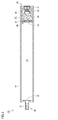
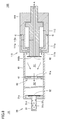
- FIG. It is a schematic sectional view of the hybrid type gas generator which concerns on Embodiment 1.
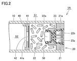
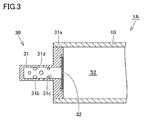
- FIG. It is an enlarged view of the partition part shown in FIG. 1 and the vicinity of an igniter assembly. It is an enlarged view of the nozzle assembly vicinity shown in FIG.
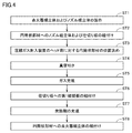
- FIG. It is a flow chart which shows the manufacturing method of the hybrid type gas generator which concerns on Embodiment 1.
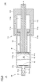
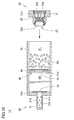
- FIG. It is a schematic cross-sectional view which shows the process of assembling a nozzle assembly and a partition plate to a cylindrical member. It is a schematic cross-sectional view which shows the positioning process with respect to the head part of the compressed gas filling apparatus. It is a schematic cross section which shows a vacuuming process. It is a schematic cross section which shows a gas filling process.
- FIG. 1 It is a schematic cross-sectional view which shows the process of assembling the 1st burst plate to a partition plate. It is a schematic cross-sectional view which shows the process of assembling an igniter assembly to a cylindrical member. It is a schematic cross-sectional view which shows the gas filling process in the manufacturing method of the hybrid type gas generator which concerns on a modification. It is a schematic cross-sectional view of the stored type gas generator which concerns on Embodiment 2.
- FIG. 1 is a schematic cross-sectional view of the hybrid gas generator according to the first embodiment.
- 2 is an enlarged view of the vicinity of the partition and igniter assembly of the hybrid gas generator shown in FIG. 1
- FIG. 3 is an enlarged view of the vicinity of the nozzle assembly.
- the hybrid gas generator 1A has a long, generally cylindrical outer shape as a whole.
- the hybrid gas generator 1A includes a cylindrical member 10 as a cylindrical member, an igniter assembly 20, a nozzle assembly 30, a partition 40, a heating agent 50, and a compressed gas that does not appear in the figure. Equipped with.
- the housing of the hybrid gas generator 1A is mainly composed of a cylindrical member 10, an igniter assembly 20, a nozzle assembly 30, and a partition 40.
- the exothermic agent 50 and the compressed gas are contained inside a housing constituted by the cylindrical member 10, the igniter assembly 20, the nozzle assembly 30, and the partition 40.
- the igniter assembly 20 is assembled to the cylindrical member 10 so as to close the opening end located on one end side in the axial direction of the cylindrical member 10, and the nozzle assembly 30 is the cylindrical member 10. It is assembled to the cylindrical member 10 so as to close the open end located on the other end side in the axial direction.
- the partition portion 40 is assembled at a predetermined position inside the cylindrical member 10 so as to partition the space inside the cylindrical member 10 in the axial direction of the cylindrical member 10.
- the space inside the housing is defined by the ignition chamber S1 defined by the cylindrical member 10, the igniter assembly 20, and the partition 40, and the cylindrical member 10, the nozzle assembly 30, and the partition 40. It is partitioned into a tank chamber S2.
- the ignition chamber S1 contains a heating agent 50
- the tank chamber S2 contains a compressed gas.
- the cylindrical member 10 is composed of a long cylindrical member in which only one end and the other end in the axial direction are open.
- the cylindrical member 10 does not have a gas injection port for injecting gas into its peripheral wall, and naturally does not have a sealing pin for sealing the gas injection port.
- the cylindrical member 10 functions as a pressure partition wall, and is made of a metal member such as stainless steel or steel.
- a metal member such as stainless steel or steel.
- chromium, manganese, molybdenum, niobium, nickel or the like is added so as to have excellent corrosion resistance. It is preferable that it is made of a steel material.
- the igniter assembly 20 has a holder 21, an igniter 22, and a resin molding portion 23.
- the igniter assembly 20 is formed by fixing the holder 21 and the igniter 22 by using the resin molding portion 23, and is configured as a pre-integrated part. As described above, the igniter assembly 20 is assembled to the cylindrical member 10 so as to close the open end of the cylindrical member 10 which is located on one end side in the axial direction.
- the holder 21 is made of a member having a substantially cylindrical outer shape, and has a penetrating portion 21a extending in the axial direction.
- the penetrating portion 21a is a portion where the igniter 22 is housed and the resin molding portion 23 is provided.
- the holder 21 functions as a pressure partition wall, and is made of a metal member such as stainless steel or steel.
- the igniter 22 is for generating a flame and is made of a pyrotechnic product generally called a squib.
- the igniter 22 has an ignition unit 22a and a pair of terminal pins 22b.
- the ignition unit 22a includes an ignition agent that ignites and burns during operation to generate a flame, and a resistor (bridge wire) for igniting the ignition agent.
- the pair of terminal pins 22b are connected to the ignition unit 22a to ignite the ignition charge.
- the ignition portion 22a includes a squib cup formed in a cup shape, and an embolus that closes the open end of the squib cup and that holds the pair of terminal pins 22b inserted therethrough.
- the above-mentioned resistor is attached so as to connect the tips of the pair of terminal pins 22b inserted in the squib cup, and the ignition charge is provided in the squib cup so as to surround the resistor or close to the resistor. It has a loaded configuration.
- nichrome wire or the like is generally used as the resistor, and ZPP (zirconium/potassium perchlorate), ZWPP (zirconium/tungsten/potassium perchlorate), lead tricinate or the like is generally used as the ignition charge.
- ZPP zirconium/potassium perchlorate
- ZWPP zirconium/tungsten/potassium perchlorate
- lead tricinate or the like is generally used as the ignition charge.
- the squib cup and embolus described above are generally made of metal or plastic.
- a predetermined amount of current flows through the resistor via the terminal pin 22b.
- Joule heat is generated in the resistor and the ignition charge starts burning.
- the hot flame generated by the combustion bursts the squib cup containing the ignition charge.
- the time from the current flowing through the resistor until the igniter 22 is activated is generally 2 [ms] or less when a nichrome wire is used for the resistor.
- the resin molding portion 23 is made of a resin portion formed by injection molding (more specifically, so-called insert molding), and is fixed to both the holder 21 and the igniter 22.
- the resin molding portion 23 is formed by using a mold during injection molding to pour a fluid resin material between the holder 21 and the igniter 22 so as to fill the space between them and solidify the resin molding portion 23. can do.
- the penetrating portion 21a of the holder 21 is in a state of being embedded by the igniter 22 and the resin molding portion 23, and the resin molding portion 23 can ensure the sealing property in the portion.
- a resin material having excellent heat resistance, durability, corrosion resistance and the like after curing is suitably selected and used.
- a thermosetting resin typified by an epoxy resin
- a polybutylene terephthalate resin typified by a polyethylene terephthalate resin, a polyamide resin (for example, nylon 6 or nylon 66), a polypropylene sulfide resin, a polypropylene oxide resin, or the like.
- a thermoplastic resin typified by an epoxy resin
- a thermosetting resin typified by an epoxy resin
- a polybutylene terephthalate resin for example, nylon 6 or nylon 66
- a polypropylene sulfide resin for example, nylon 6 or nylon 66
- a polypropylene oxide resin a polypropylene oxide resin
- the resin molding portion 23 is provided with a recess 23a that is exposed to the outside.
- a pair of terminal pins 22b of the igniter 22 are arranged inside the recess 23a.
- the female connector portion including the recess 23a and the pair of terminal pins 22b is provided on the end surface on the one end side of the cylindrical member 10 described above.
- the female connector part is a part for receiving a male connector (not shown) of a harness for connecting the igniter 22 and a control unit (not shown).
- the female connector portion is exposed to the outside of the housing, and the male connector described above is inserted into the female connector portion to realize electrical conduction between the core wire of the harness and the terminal pin 22b. Will be.
- the fixing method of the igniter 22 to the holder 21 is not limited to the fixing method using the resin molding portion 23 described above, and other fixing methods may be used.
- the holder 21 of the igniter assembly 20 is press-fitted into the above-mentioned opening end on one end side of the cylindrical member 10, and the contact portion between the holder 21 and the cylindrical member 10 or a contact portion thereof. They are fixed by joining them in the vicinity.
- electron beam welding, laser welding, resistance welding, friction welding and the like can be preferably used for joining the holder 21 and the cylindrical member 10.
- the method of fixing the igniter assembly 20 to the cylindrical member 10 is not limited to the above-described fixing method using press fitting and welding, and other fixing methods may be used.
- the nozzle assembly 30 has a nozzle 31 and a second rupturable plate 32.
- the nozzle assembly 30 is configured as a component integrated in advance by joining the second rupturable plate 32 to the nozzle 31.
- the nozzle assembly 30 is assembled to the cylindrical member 10 so as to close the open end located on the other end side in the axial direction of the cylindrical member 10.
- the nozzle 31 has a substantially disk-shaped base portion 31a having a through hole in the center and a substantially cylindrical nozzle portion 31b with one end closed.
- the nozzle portion 31b is provided so as to project from the center of the base portion 31a along the axial direction, and is thereby positioned so as to extend toward the outside of the housing.
- the nozzle 31 functions as a pressure partition wall, and is made of, for example, a metal member such as stainless steel or steel.
- a steel material added with chromium, manganese, molybdenum, niobium, nickel or the like so as to have excellent corrosion resistance Is preferably configured.
- the nozzle 31 has a hollow flow path portion 31c inside.
- the flow passage portion 31c is configured by a through hole provided in the base portion 31a and a hollow portion provided in the nozzle portion 31b, so that the flow passage portion 31c opens toward the tank chamber S2. It has an opening at one end. The opening provided on the tank chamber S2 side of the flow path portion 31c is closed by the second rupturable plate 32.
- a plurality of gas outlets 31d are provided on the peripheral wall of the nozzle portion 31b, and the plurality of gas outlets 31d are all in communication with the flow passage portion 31c.
- the plurality of gas ejection ports 31d are portions for ejecting gas toward the outside during operation of the hybrid gas generator 1A, and are closed by the second rupturable plate 32 via the flow passage portion 31c. There is.
- the second rupturable plate 32 has a thin plate outer shape, and is fixed to the base portion 31a of the nozzle 31 so as to close the opening provided on the tank chamber S2 side of the flow passage portion 31c as described above. ing.
- the second rupturable plate 32 can be ruptured due to the operation of the igniter 22 and the rupture of the first rupturable plate 42 described later, and is preferably made of a metal member.
- the second rupturable plate 32 is SUS316 (JIS standard symbol) or Inconel (registered trademark) from the viewpoint of corrosion resistance. It is desirable that the member is made of a nickel alloy formed of a thin metal plate such as).
- a thin metal plate having a heat resistance and a corrosion resistance (for example, a thickness of about 200 [ ⁇ m]) is preferably used, and Ni: 10 wt%, Cr: 23 wt%, A thin plate made of stainless steel or Inconel alloy (Inconel 625) having a composition ratio of Mn: 6% by weight, Mo: 2% by weight, C: 0.01% by weight, N: 0.5% by weight, and others is particularly preferable. Used for.
- the second rupturable plate 32 is fixed by being joined to the nozzle 31 by, for example, electron beam welding, laser welding, resistance welding or the like.
- the base portion 31a of the nozzle 31 of the nozzle assembly 30 is press-fitted into the above-mentioned opening end on the other end side of the cylindrical member 10, and the contact portion between the nozzle 31 and the cylindrical member 10 is formed. Alternatively, they are fixed by being joined in the vicinity thereof.
- electron beam welding, laser welding, resistance welding, friction welding, or the like can be suitably used for joining the nozzle 31 and the cylindrical member 10.
- the method of fixing the nozzle assembly 30 to the cylindrical member 10 is not limited to the above-mentioned fixing method using press fitting and welding, and other fixing methods may be used.
- the partition section 40 has a partition plate 41 and a first rupturable plate 42. As described above, the partition portion 40 is assembled at a predetermined position inside the cylindrical member 10 so as to partition the space inside the cylindrical member 10 into the ignition chamber S1 and the tank chamber S2.
- the partition plate 41 is made of a member having an annular plate-like outer shape, and a communication hole 41a penetrating along the axial direction is provided at the center of the partition plate 41.
- the communication hole 41a is a part for communicating the ignition chamber S1 and the tank chamber S2.
- the opening located on the ignition chamber S1 side of the communication hole 41a is closed by the first rupturable plate 42.
- the above-mentioned communication hole 41a also functions as a gas injection port for injecting gas into the tank chamber S2 at the time of manufacturing the hybrid gas generator 1A. Note that this point will be described later in detail.
- the partition plate 41 functions as a pressure partition wall, and is made of, for example, a metal member such as stainless steel or steel.
- the partition plate 41 is made of a steel material to which chromium, manganese, molybdenum, niobium, nickel, etc. are added so as to have excellent corrosion resistance. It is preferably configured.
- the first rupturable plate 42 has a thin plate-shaped outer shape, and is fixed to the partition plate 41 so as to close the opening located on the ignition chamber S1 side of the communication hole 41a as described above.
- the first rupturable plate 42 is capable of rupturing due to a pressure increase in the ignition chamber S1 due to the operation of the igniter 22, and is preferably composed of a metal member.
- the first rupturable plate 42 is SUS316 (JIS standard symbol) or Inconel (registered trademark) from the viewpoint of corrosion resistance. It is desirable that the member is made of a nickel alloy formed of a thin metal plate such as).
- a metal thin plate having heat resistance and corrosion resistance for example, a thickness of about 200 [ ⁇ m]
- a thin plate made of stainless steel or Inconel alloy (Inconel 625) having a composition ratio of Mn: 6% by weight, Mo: 2% by weight, C: 0.01% by weight, N: 0.5% by weight, and others is particularly preferable. Used for.
- the first rupturable plate 42 is fixed by being joined to the partition plate 41 by resistance welding.
- the first rupture plate 42 is addressed to the main surface of the pair of main surfaces located in the thickness direction of the partition plate 41 and facing the ignition chamber S1 and welded to the main surface.
- the welding of the first rupturable plate 42 to the partition plate 41 is performed after the partition plate 41 is assembled to the cylindrical member 10.
- the partition plate 41 is press-fitted inside the cylindrical member 10 and is fixed by joining them at or near a contact portion between the partition plate 41 and the cylindrical member 10.
- electron beam welding, laser welding, resistance welding, friction welding and the like can be preferably used for joining the partition plate 41 and the cylindrical member 10.
- the method of fixing the partition plate 41 to the cylindrical member 10 is not limited to the above-mentioned fixing method using press fitting and welding, and other fixing methods may be used.
- the exothermic agent 50 is housed in the ignition chamber S1 defined by the cylindrical member 10, the igniter assembly 20, and the partition 40.
- the exothermic agent 50 is composed of a chemical that generates high temperature heat by burning.
- the exothermic agent 50 is heat for compensating for energy loss that can occur due to adiabatic expansion of the compressed gas by the cleavage of the first rupturable plate 42 and the second rupturable plate 32 during operation of the hybrid gas generator 1A. Is supplied to the compressed gas.
- composition comprising a metal powder/oxidizing agent represented by B/KNO 3 , B/NaNO 3 , Sr(NO 3 ) 2 and the like, or guanidine nitrate or nitroguanidine , Titanium hydride/potassium perchlorate, B/5-aminotetrazole/potassium nitrate, ammonium perchlorate/potassium perchlorate/nitroguanidine, Sr A composition comprising (NO 3 ) 2 /nitroguanidine is used.
- a powdery one or one molded into a predetermined shape with a binder can be used.
- the shape of the exothermic agent 50 formed by the binder include various shapes such as a granular shape, a cylindrical shape, a sheet shape, a spherical shape, a single-hole cylinder shape, a perforated cylinder shape, and a tablet shape.
- the compressed gas is contained in the tank chamber S2 defined by the cylindrical member 10, the nozzle assembly 30, and the partition 40.
- the compressed gas is released to the outside when the second rupturable plate 32 is opened, so that the compressed gas is provided adjacent to the hybrid gas generator 1A. It is intended to inflate and deploy the bag.
- various inert gases can be used, and for example, helium gas, argon gas, neon gas, nitrogen gas, carbon dioxide gas, etc. can be used.
- the igniter 22 operates by receiving the energization from the control unit described above.
- the igniter 22 operates, the ignition charge filled in the ignition part 22a is ignited by being heated by the resistor, and the ignition charge is burned, so that the ignition part 22a bursts.
- the exothermic agent 50 housed in the ignition chamber S1 is ignited by the igniter 22 and burned.
- the pressure and temperature of the ignition chamber S1 rise due to the combustion of the igniting charge and the heat generating agent 50, and accordingly, the portion of the first rupturable plate 42 facing the communication hole 41a is split. With the tearing of the first rupturable plate 42, the ignition chamber S1 and the tank chamber S2 are in communication with each other through the communication hole 41a.
- the pressure and temperature of the tank chamber S2 also rise, and along with this, of the second rupturable plate 32. Cleavage occurs at the portion facing the flow path portion 31c.
- the tank chamber S2 and the plurality of gas ejection ports 31d are in communication with each other via the flow path portion 31c.
- the compressed gas stored in the tank chamber S2 reaches the plurality of gas ejection ports 31d through the flow path portion 31c, and thereafter is ejected outward from the plurality of gas ejection ports 31d. Become.
- the gas ejected from the plurality of gas ejection ports 31d to the outside of the hybrid gas generator 1A is introduced into the inside of an airbag provided adjacent to the hybrid gas generator 1A, and Inflate and deploy.
- the hybrid gas generator 1A corresponds to the peripheral wall of the cylindrical member 10 among the wall portions of the housing of the portion defining the tank chamber S2 in which the compressed gas is sealed.
- the first rupture plate 42 provided in the partition plate 41 so as to close the communication hole 41a provided in the partition plate 41 is not provided with an opening in the part to be opened. It is welded to the main surface of the partition plate 41 of the portion located on the one end side (that is, the open end on the side to which the igniter assembly 20 is assembled).
- Such a characteristic configuration results from the fact that the hybrid gas generator 1A according to the present embodiment is manufactured according to the method for manufacturing the hybrid gas generator according to the present embodiment described below.
- the communication hole 41a provided in the partition plate 41 is used as a gas injection port, and the communication hole 41a after the compressed gas is injected. Is closed by the first rupturable plate 42.
- FIG. 4 is a flow chart showing the method of manufacturing the hybrid gas generator according to the present embodiment
- FIGS. 5 to 10 are schematic cross-sectional views in each step shown in FIG.
- step ST1 when manufacturing the hybrid gas generator 1A according to the present embodiment, first, in step ST1, the igniter assembly 20 and the nozzle assembly 30 are manufactured, respectively.
- the igniter assembly 20 as an integral part is manufactured, and the second rupture plate 32 is, for example, resistance welded to the nozzle 31.
- the nozzle assembly 30 is manufactured as an integral part by being welded together.
- step ST2 the nozzle assembly 30 and the partition plate 41 are assembled to the cylindrical member 10, respectively.
- the base portion 31a of the nozzle 31 of the nozzle assembly 30 is inserted into the opening end located on the other end side of the cylindrical member 10 in the axial direction. Then, the nozzle 31 is welded to the cylindrical member 10 by, for example, laser welding or the like, so that the nozzle assembly 30 is assembled to the cylindrical member 10. Further, the partition plate 41 is press-fitted by being inserted from the opening end located on the one end side in the axial direction of the cylindrical member 10 so as to enter the inside of the cylindrical member 10 beyond the one end, and thereafter. The partition plate 41 is assembled to the cylindrical member 10 by welding the partition plate 41 to the cylindrical member 10 by, for example, laser welding or the like.
- step ST3 the cylindrical member 10 is positioned with respect to the head portion 110 of the compressed gas filling device 100.
- the compressed gas filling device 100 is configured by combining a gas filling device and a welding device, and has a block-shaped head portion 110.
- the head portion 110 includes a gas filling head 111 and a welding head 112, and the welding head 112 is slidably incorporated in the gas filling head 111.
- a ventilation passage 111a which is selectively switched to a gas supply source and a negative pressure source (not shown) is provided, and one end of the ventilation passage 111a is the gas filling head 111. It has an opening on the main surface 111b.
- the welding head 112 has a substantially cylindrical outer shape, and is slidably held by the gas filling head 111 as described above.
- a suction path 112a connected to a negative pressure source (not shown) is provided inside the welding head 112, and one end of the suction path 112a is opened at the main surface 112b of the welding head 112.
- the main surface 111b of the gas filling head 111 and the main surface 112b of the welding head 112 are arranged so as to be parallel to each other, and the main surface 112b of the welding head 112 is driven by driving the welding head 112. , Can be moved so as to project from the main surface 111b of the gas filling head 111. It should be noted that one end of the ventilation path 111 a that opens on the main surface 111 b of the gas filling head 111 is arranged so as to surround the welding head 112.
- the welding head 112 holds the first rupturable plate 42 in advance. More specifically, the first rupture plate 42 is in a state of being previously addressed to the main surface 112b of the welding head 112, and in this state, a negative pressure is applied to the suction path 112a by driving the above-mentioned negative pressure source. By being generated, the first rupturable plate 42 is held by the welding head 112 (in the figure, the suction direction by the negative pressure source is schematically shown by the arrow A).
- the opening end on the one end side in the axial direction of the cylindrical member 10 to which the nozzle assembly 30 and the partition plate 41 are assembled in step ST2 comes into contact with the main surface 111b of the gas filling head 111.
- the cylindrical member 10 is positioned with respect to the head portion 110 of the compressed gas charging device 100 by being pressed against.
- the above-mentioned one end side end surface of the cylindrical member 10 is brought into contact with the main surface 111b of the gas filling head 111, whereby a partition plate 41 provided with a communication hole 41a as a gas injection port and a cylinder.
- a closed space is formed by the member 10 and the main surface 111b of the gas filling head 111 (see FIG. 7).
- the first rupture plate 42 is described above by covering the end portion of the welding head 112 holding the first rupture plate 42 with the above-mentioned opening end on one end side of the cylindrical member 10. It is held by the welding head 112 inside the closed space (see FIG. 7).
- step ST4 evacuation is performed by using the above-mentioned gas filling device provided with the gas filling head 111.
- the ventilation path 111a provided in the gas filling head 111 is connected to the negative pressure source described above, and the negative pressure source is driven, whereby the above-mentioned closed space and Air in the tank chamber S2 that communicates with the closed space through the communication hole 41a is sucked, and the sucked air is exhausted to the outside through the ventilation path 111a (in the figure, by the negative pressure source).
- the suction direction is schematically indicated by arrow B). The evacuation is carried out until the pressure in the tank chamber S2 reaches a predetermined degree of vacuum.
- step ST5. This gas filling is performed by continuing to use the above-mentioned gas filling device equipped with the gas filling head 111.
- the ventilation path 111a provided with the gas filling head 111 is switched from the negative pressure source described above to the gas supply source described above, and the gas supply source is driven.
- the gas is sent into the above-mentioned closed space and the tank chamber S2 communicating with the closed space via the communication hole 41a, and the sent gas is compressed, so that the tank chamber S2 is filled with the compressed gas.
- the supply direction of the gas sent by the gas supply source is schematically shown by an arrow C).
- the gas filling is performed until the pressure in the tank chamber S2 reaches a predetermined high pressure state (for example, about 30 [MPa] to 90 [MPa]).
- the one end of the ventilation path 111a opening on the main surface 111b of the gas filling head 111 functions as a gas delivery port for delivering the gas, and the gas delivered from the gas delivery port has the above-mentioned closed space.
- the gas is sent to the tank chamber S2 from the communication hole 41a as a gas injection port.
- step ST6 the first rupturable plate 42 is assembled to the partition plate 41.
- the assembling of the first rupturable plate 42 is carried out by using the above-mentioned welding device equipped with the welding head 112.
- the plate 42 is moved by driving the welding head 112, so that the first rupturable plate 42 is pressed against the partition plate 41 so that the first rupturable plate 42 covers the communication hole 41a as the gas injection port.
- the first rupture plate 42 in a state of being pressed against the partition plate 41 by operating the welding head 112 (that is, a current for resistance welding is applied to the welding head 112). Are welded to the partition plate 41. As a result, a welded joint is formed at or near the contact portion between the partition plate 41 and the first rupturable plate 42 so as to surround the communication hole 41a, and the first rupturable plate 42 is fixed to the partition plate 41. To be done.
- the communication hole 41a as a gas injection port provided in the partition plate 41 is closed by the first rupturable plate 42
- the tank chamber S2 filled with the compressed gas is closed by the first rupturable plate 42.
- the compressed gas is sealed in the tank chamber S2.
- step ST7 the exothermic agent 50 is filled in step ST7, and then the igniter assembly 20 is assembled to the cylindrical member 10 in step ST8.
- the opening end on the one end side is provided inside the one end side in the axial direction of the cylindrical member 10 separated from the head portion 110 of the compressed gas charging device 100.
- a predetermined amount of the heating agent 50 is charged from the above, and then the holder 21 of the igniter assembly 20 is press-fitted into the opening end located on the one end side of the cylindrical member 10 as described above.
- the holder 21 is welded to the cylindrical member 10 by, for example, laser welding or the like, so that the igniter assembly 20 is assembled to the cylindrical member 10.
- the communication hole 41a provided in the partition plate 41 is used as a gas inlet.
- the communication hole 41a is closed by the first rupturable plate 42 after the compressed gas is injected. Therefore, by adopting the manufacturing method or by using the hybrid gas generator 1A according to the above-described present embodiment, it is not necessary to provide the housing with a structural portion used only for enclosing the compressed gas, and The configuration of the generator itself can be simplified and the assembly work can be facilitated.
- the above-mentioned one end side end face in the axial direction of the cylindrical member 10 is pressed against the head portion 110 of the compressed gas charging device 100. Therefore, the volume of the closed space described above can be significantly reduced. Therefore, when evacuating, the vacuum degree of the tank chamber S2 can be lowered to a predetermined vacuum degree within a short time, and when the gas is filled, a predetermined high pressure state can be reached within a short time. The pressure in the tank chamber S2 can be increased. Therefore, the time required for manufacturing can be shortened, which leads to a reduction in manufacturing cost.
- the compressed gas can be filled in the housing by using the compressed gas filling device 100 provided with the small head portion 110 having the above-described configuration.
- the manufacturing equipment can be significantly downsized as compared with the conventional compressed gas filling device.
- the volume of the closed space described above is significantly narrowed. It is possible to suppress the variation in the heat generation amount. Therefore, it is possible to suppress variation in the filling amount of the compressed gas between manufactured products, and it is possible to manufacture a hybrid gas generator that can obtain a desired gas output with higher yield.
- the portion of the housing that is pressed against the head portion 110 of the compressed gas charging device 100 (that is, one of the above-described ones in the axial direction of the cylindrical member 10). Since the shape of the end surface on the end side is a planar shape, it is easier to secure the airtightness of the closed space described above and to more easily generate the high pressure gas than when the gas inlet is provided in the curved peripheral wall of the cylindrical member 10. It will also be possible to enclose.
- the communication hole 41a provided in the partition plate 41 assembled at a predetermined position inside the cylindrical member 10 serves as a gas inlet. Since it is used, the compressed gas filling part that defines the tank chamber and the detonation part that defines the ignition chamber that contains the combustion agent and that has the igniter assembly assembled are manufactured as separate units. After that, it is not necessary to combine these, and it becomes possible to manufacture a hybrid gas generator extremely easily.
- FIG. 11 is a schematic cross-sectional view showing a gas filling step in the method of manufacturing the hybrid gas generator according to the modification based on the first embodiment described above.
- FIG. 11 a method of manufacturing the hybrid gas generator according to the modification will be described.
- a cylindrical member 10 is provided on the main surface of the head portion 110 (that is, the main surface 111b of the gas filling head 111).
- the above-mentioned one end face on one end side in the axial direction is configured to be pressed against the above-mentioned one
- the above-mentioned case is described, but a compressed gas filling device provided with a head portion 110 having another shape is used. You can also
- the compressed gas filling device 100'used in the method for manufacturing the hybrid gas generator according to the present modification is provided with a recess 111c on the main surface 111b of the gas filling head 111.
- the end of the welding head 112 is arranged so as to project from the bottom surface of the recess 111c.
- a seal member 111d made of packing or the like is arranged on the peripheral surface of the recess 111c so as to protrude inward.
- the above-mentioned opening end on one end side in the axial direction of the cylindrical member 10 to which the nozzle assembly 30 and the partition plate 41 are assembled is formed.
- the above-mentioned outer peripheral surface on one end side of the cylindrical member comes into contact with the head portion 110 via the sealing member 111d.
- a closed space is formed between the partition plate 41 and the head section 110.
- the closed space as described above between these without directly abutting the housing and the head portion.
- a compressed gas filling device having a chamber and a welding head arranged in the chamber, a cylindrical member to which a nozzle assembly and a partition plate are assembled is arranged in the chamber to compress the inside of the chamber.
- the tank chamber may be filled with compressed gas by filling with gas, and then the compressed gas may be sealed in the tank chamber by welding the first rupture plate to the partition plate using a welding head.
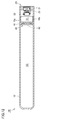
- FIG. 12 is a schematic cross-sectional view of the stored gas generator according to the second embodiment.
- the configuration of the stored gas generator 1B according to the present embodiment will be described with reference to FIG.
- the stored gas generator 1B according to the present embodiment has a so-called reverse flow structure.
- the stored gas generator 1B has a configuration similar to that of the hybrid gas generator 1A according to the above-described first embodiment, and the hybrid gas generator is generated.
- the housing configuration of the portion mainly defining the tank chamber S2 is different, and in addition to this, the nozzle assembly 30 and the heating agent 50 (both refer to FIG. 1 and the like) are provided.
- the configuration is different in that it is not formed, the formation positions of the plurality of gas ejection ports, the configuration in the vicinity of the plurality of gas ejection ports, and that only a single rupturable plate 42 is provided.
- the cylindrical member 10 is a long bottomed cylindrical member having one end in the axial direction as an open end and the other end in the axial direction as a closed end.
- the igniter assembly 20 is assembled to the above-mentioned opening end on one end side in the axial direction.
- a partition portion 40 is assembled at a predetermined position in the space inside the cylindrical member 10, whereby the space inside the cylindrical member 10 is divided into an ignition chamber S1 and a tank chamber S2. There is.
- a plurality of gas outlets 10a are provided in the cylindrical member 10 of the portion defining the ignition chamber S1.
- the plurality of gas outlets 10a are portions for ejecting gas to the outside when the stored type gas generator 1B is operating.
- a metal sealing tape 10b is attached to the inner peripheral surface of the cylindrical member 10 of the portion defining the ignition chamber S1 so as to close the plurality of gas outlets 10a.
- the sealing tape 10b an aluminum foil or the like having an adhesive member coated on one side can be preferably used, and the airtightness of the ignition chamber S1 is ensured by the sealing tape 10b.
- the opening located on the ignition chamber S1 side of the communication hole 41a provided in the partition plate 41 is closed by the rupture plate 42. That is, the rupture plate 42 is directed to the main surface of the pair of main surfaces located in the thickness direction of the partition plate 41 facing the ignition chamber S1 and welded to the main surface.
- the igniter 22 operates by receiving the energization from the control unit described above.
- the igniter 22 operates, the ignition charge filled in the ignition part 22a is ignited by being heated by the resistor, and the ignition charge is burned, so that the ignition part 22a bursts.
- the compressed gas flows into the ignition chamber S1 through the communication hole 41a, and then is directed to the outside from the plurality of gas ejection ports 10a. Will spurt out.
- the gas ejected from the plurality of gas ejection ports 10a to the outside of the stored gas generator 1B is introduced into the inside of an airbag provided adjacent to the stored gas generator 1B, and Inflate and deploy.
- the stored-type gas generator 1B corresponds to the peripheral wall of the cylindrical member 10 among the wall portions of the housing defining the tank chamber S2 in which the compressed gas is enclosed.
- the opening is not provided in the portion to be formed, and the rupture plate 42 provided in the partition plate 41 so as to close the communication hole 41a provided in the partition plate 41 is the one end of the cylindrical member 10 described above. It is welded to the main surface of the partition plate 41 of the portion located on the side (that is, the open end on the side to which the igniter assembly 20 is assembled).
- Such a characteristic configuration can be realized by manufacturing the stored type gas generator according to the manufacturing method according to the manufacturing method of the hybrid type gas generator according to the first embodiment described above. Therefore, even when the stored type gas generator 1B according to the present embodiment is used, it is not necessary to provide the housing with a structural portion used only for filling the compressed gas, and the configuration of the gas generator itself can be simplified and the assembly work can be performed. It can be realized easily.
- the ventilation passage provided in the gas filling head of the compressed gas filling device is selectively and switchably connected to the gas supply source and the negative pressure source.
- the gas filling head is provided with a ventilation path independently connected to the gas supply source and the negative pressure source, and the gas supply source and the negative pressure source are respectively provided. It may be configured to be driven at different timings.
- the present invention is applied to the cylinder type gas generator incorporated in the side airbag device as an example.
- the object of application of the present invention is not limited to this, and a cylinder type gas generator incorporated in a curtain airbag device, a knee airbag device, a seat cushion airbag device, or the like, and a long type like a cylinder type gas generator.
- the present invention can be applied to a so-called T-shaped gas generator or the like having a circular outer shape.
Landscapes
- Physics & Mathematics (AREA)
- Fluid Mechanics (AREA)
- Engineering & Computer Science (AREA)
- Mechanical Engineering (AREA)
- Air Bags (AREA)
Abstract
本発明に基づくガス発生器の製造方法は、タンク室(S2)を規定する部分のハウジングに設けられたガス注入口(41a)を介してタンク室(S2)にガスを送り込むことにより、タンク室(S2)を圧縮ガスにて満たす工程と、点火器の作動に起因して開裂が可能な破裂板(42)にてガス注入口(41a)が閉鎖されるように破裂板(42)をハウジングに溶接することにより、圧縮ガスにて満たされた状態にあるタンク室(S2)を封止する工程とを備える。
Description
本発明は、ハウジングの内部に設けられたタンク室に封入された圧縮ガスが、点火器が作動することで外部に向けて噴出するように構成されたガス発生器の製造方法ならびに当該ガス発生器に関する。
自動車等の乗員保護装置であるエアバッグ装置に組み込まれるガス発生器は、車両等衝突時に車両に別途設けられたコントロールユニットからの通電によって点火器が着火し、これに起因して瞬時に多量のガスが外部に向けて放出されるように構成されたものであり、これによってエアバッグを膨張および展開させる機器である。当該ガス発生器は、そのガスの放出メカニズムに基づき、パイロ型ガス発生器と、ストアード型ガス発生器と、ハイブリッド型ガス発生器とに大別される。
パイロ型ガス発生器は、ガス発生剤がハウジングの内部に収容されてなるものであり、ガス発生剤が点火器の作動によって着火されて燃焼し、これによって多量のガスが発生させられて外部に放出されるものである。
ストアード型ガス発生器は、圧縮ガスがハウジングの内部に封入されてなるものであり、圧縮ガスを封止する破裂板が点火器の作動によって開裂し、これによって圧縮ガスが外部に放出されるものである。
ハイブリッド型ガス発生器は、圧縮ガスがハウジングの内部に封入されるとともに、さらに発熱剤がハウジングの内部に収容されてなるものであり、圧縮ガスを封止する破裂板が点火器の作動によって開裂するとともに、発熱剤が点火器の作動によって着火されて燃焼し、これにより圧縮ガスが断熱膨張することで発生し得るエネルギーロスを当該発熱剤が燃焼することで生じる熱によって補いつつ、圧縮ガスが外部に放出されるように構成されたものである。
ここで、上述した各種のガス発生器のうち、ストアード型ガス発生器の具体的な構造が開示された文献としては、たとえば特開2003-182506号公報(特許文献1)等があり、ハイブリッド型ガス発生器の具体的な構造が開示された文献としては、たとえば特開2009-51236号公報(特許文献2)や特開2016-68658号公報(特許文献3)等がある。
このうち、上記特許文献1に開示のストアード型ガス発生器および上記特許文献2に開示のハイブリッド型ガス発生器は、一般にブローダウン構造と称される構造のものであり、圧縮ガスが封入されたタンク室と点火器が収容された点火室とを仕切る仕切り部に連通孔が設けられるとともに、タンク室を規定する部分のハウジングにガス噴出口が設けられてなるものである。当該ブローダウン構造のストアード型ガス発生器およびハイブリッド型ガス発生器においては、連通孔およびガス噴出口がいずれもタンク室に面するように設けられているため、上述した破裂板は、これら連通孔およびガス噴出口をそれぞれ個別に閉鎖するように一対設けられる。
一方、上記特許文献3に開示のハイブリッド型ガス発生器は、一般にリバースフロー構造と称される構造のものであり、圧縮ガスが封入されたタンク室と点火器が収容された点火室とを仕切る仕切り部に連通孔が設けられるとともに、点火室を規定する部分のハウジングにガス噴出口が設けられてなるものである。当該リバースフロー構造のハイブリッド型ガス発生器においては、連通孔およびガス噴出口のうちの連通孔のみがタンク室に面するように設けられているため、上述した破裂板は、この連通孔を閉鎖するように設けられ、ガス噴出口は、点火室を外部から気密に封止する封止部材によって閉鎖されるのみである。
上述したストアード型ガス発生器およびハイブリッド型ガス発生器においては、ハウジングに設けられたタンク室に圧縮ガスを封入することが必要になる。この圧縮ガスの封入方法としては、たとえば特開2000-227199号公報(特許文献4)に開示の方法が知られている。
当該特許文献4に開示の圧縮ガスの封入方法は、ハウジングを構成する円筒状部材の周壁のうちのタンク室を規定する部分に予めガス注入口を設けておき、当該ガス注入口を介してガスをタンク室に送り込んだ後に、当該ガス注入口が封止ピンによって閉鎖されるように当該封止ピンを円筒状部材に溶接するものである。
しかしながら、上記特許文献4に開示される如くの圧縮ガスの封入方法を採用してガス発生器を製造することとした場合には、ハウジングの所定部位に圧縮ガスの封入にのみ用いる構造部(すなわち、上述した円筒状部材の周壁に設けられたガス注入口および当該ガス注入部を閉鎖する封止ピンならびにその溶接部等)を設ける必要があり、ガス発生器自体の構成の複雑化、部品点数の増加、組立作業の煩雑化等を招来し、結果として製造コストが増大してしまう問題があった。
したがって、本発明は、上述した問題に鑑みてなされたものであり、ハウジングの内部に圧縮ガスが封入されてなるガス発生器において、ガス発生器自体の構成の簡素化と組立作業の容易化とを図ることを目的とする。
本発明に基づくガス発生器の製造方法は、ハウジングの内部に設けられたタンク室に封入された圧縮ガスが、点火器が作動することで外部に向けて噴出するように構成されたガス発生器を製造するための方法であって、上記タンク室を規定する部分の上記ハウジングに設けられたガス注入口を介して上記タンク室にガスが送り込まれることにより、上記タンク室が圧縮ガスにて満たされる工程と、上記点火器の作動に起因して開裂が可能な破裂板にて上記ガス注入口が閉鎖されるように上記破裂板が上記ハウジングに溶接されることにより、圧縮ガスにて満たされた状態にある上記タンク室が封止される工程とを備えている。
ここで、上述したハウジングには、ガス発生器を構成する各種の部材のうち、ガス発生器の骨格を成す各種の壁部を構成する部材が含まれ、より特定的には、圧力隔壁として機能する部位のすべてが含まれる。すなわち、上述したハウジングには、ガス発生器の外殻を構成する部材または部位のみならず、当該ガス発生器の内部の空間を仕切る部材または部位も含まれる。
上記本発明に基づくガス発生器の製造方法にあっては、上記タンク室が圧縮ガスにて満たされる工程が、ガスを送り出すためのガス送出口が設けられた充填ヘッドを有するガス充填装置が用いられることによって行なわれるとともに、上記タンク室が封止される工程が、上記破裂板を上記ハウジングに溶接するための溶接ヘッドを有する溶接装置が用いられることによって行なわれることが好ましい。その場合には、上記タンク室が圧縮ガスにて満たされる工程が、上記ガス注入口が設けられた部分の上記ハウジングと上記ガス送出口が設けられた部分の上記充填ヘッドとの間に閉空間が形成されるように、上記充填ヘッドに対して上記ハウジングが位置決めされて配置される工程と、上記ガス送出口から送り出されたガスが上記閉空間を経由することで上記ガス注入口から上記タンク室に送り込まれる工程とを含んでいることが好ましく、また、上記タンク室が封止される工程が、上記タンク室が圧縮ガスにて満たされる工程が完了した後において、予め上記閉空間の内部において上記溶接ヘッドによって保持されていた上記破裂板が上記溶接ヘッドが駆動されることで移動させられ、これにより上記破裂板によって上記ガス注入口が覆われるように上記破裂板が上記ハウジングに対して押し付けられる工程と、上記ハウジングに対して押し付けられた状態にある上記破裂板が上記溶接ヘッドが稼働することで上記ハウジングに溶接される工程とを含んでいることが好ましい。
上記本発明に基づくガス発生器の製造方法にあっては、上記充填ヘッドに対して上記ハウジングが位置決めされて配置される工程において、上記ハウジングと上記充填ヘッドとが密着することで上記閉空間が形成されるように、上記ハウジングと上記充填ヘッドとが当接させられてもよい。
上記本発明に基づくガス発生器の製造方法にあっては、上記ハウジングが、軸方向の一方端を少なくとも開口端として有する筒状部材を含んでおり、また、上記ガス注入口が、上記筒状部材の軸方向を向くように設けられている場合において、上記充填ヘッドに対して上記ハウジングが位置決めされて配置される工程において、上記筒状部材の上記一方端の端面が上記充填ヘッドに当接させられることが好ましい。
上記本発明に基づくガス発生器の製造方法にあっては、上記ハウジングが、上記筒状部材の上記一方端から奥まった位置に配置されるとともに上記ガス注入口が設けられてなる仕切り部をさらに含んでいる場合において、上記破裂板が上記ハウジングに対して押し付けられる工程において、上記溶接ヘッドが上記筒状部材の上記一方端を越えて上記筒状部材の内部に入り込むように駆動されることにより、上記破裂板が上記仕切り部の上記一方端側の主面に押し付けられて当該主面に溶接されることが好ましい。
本発明に基づくガス発生器は、圧縮ガスが封入されたタンク室が内部に設けられてなるハウジングと、上記ハウジングに組付けられた点火器とを備えている。上記ハウジングは、軸方向の一方端を少なくとも開口端として有する筒状部材と、上記筒状部材の上記一方端から奥まった位置に配置されることで上記筒状部材の内部の空間を仕切る仕切り部とを含んでいる。上記ハウジングの内部の空間であってかつ上記仕切り部から見て上記一方端側の空間は、上記点火器に面する点火室として構成されている。上記ハウジングの内部の空間であってかつ上記仕切り部から見て上記一方端側とは反対側の空間は、上記タンク室として構成されている。上記仕切り部には、上記点火室と上記タンク室とを連通させるための連通孔が上記筒状部材の軸方向を向くように設けられている。上記仕切り部には、上記連通孔を閉鎖するとともに、上記点火器の作動に起因して開裂が可能な破裂板が設けられており、上記破裂板は、上記仕切り部の上記一方端側の主面に溶接されている。
本発明によれば、ハウジングの内部に圧縮ガスが封入されてなるガス発生器において、ガス発生器自体の構成の簡素化と組立作業の容易化とを図ることができる。
以下、本発明の実施の形態について、図を参照して詳細に説明する。以下に示す実施の形態は、サイドエアバッグ装置に組み込まれるシリンダ型ガス発生器に本発明を適用した場合を例示するものである。なお、以下に示す実施の形態においては、同一のまたは共通する部分について図中同一の符号を付し、その説明は繰り返さない。
(実施の形態1)
図1は、実施の形態1に係るハイブリッド型ガス発生器の模式断面図である。図2は、図1に示すハイブリッド型ガス発生器の仕切り部および点火器組立体近傍の拡大図であり、図3は、ノズル組立体近傍の拡大図である。まず、これら図1ないし図3を参照して、本実施の形態に係るハイブリッド型ガス発生器1Aの構成について説明する。なお、本実施の形態に係るハイブリッド型ガス発生器1Aは、いわゆるブローダウン構造を有するものである。
図1は、実施の形態1に係るハイブリッド型ガス発生器の模式断面図である。図2は、図1に示すハイブリッド型ガス発生器の仕切り部および点火器組立体近傍の拡大図であり、図3は、ノズル組立体近傍の拡大図である。まず、これら図1ないし図3を参照して、本実施の形態に係るハイブリッド型ガス発生器1Aの構成について説明する。なお、本実施の形態に係るハイブリッド型ガス発生器1Aは、いわゆるブローダウン構造を有するものである。
図1に示すように、ハイブリッド型ガス発生器1Aは、全体として長尺略円柱状の外形を有している。ハイブリッド型ガス発生器1Aは、筒状部材としての円筒状部材10と、点火器組立体20と、ノズル組立体30と、仕切り部40と、発熱剤50と、図には現れない圧縮ガスとを備えている。
ハイブリッド型ガス発生器1Aのハウジングは、円筒状部材10と、点火器組立体20と、ノズル組立体30と、仕切り部40とによって主として構成されている。発熱剤50および圧縮ガスは、これら円筒状部材10、点火器組立体20、ノズル組立体30および仕切り部40によって構成されたハウジングの内部に収容されている。
点火器組立体20は、円筒状部材10の軸方向の一方端側に位置する開口端を閉塞するように円筒状部材10に組付けられており、ノズル組立体30は、円筒状部材10の軸方向の他方端側に位置する開口端を閉塞するように円筒状部材10に組付けられている。一方、仕切り部40は、円筒状部材10の内部の空間を当該円筒状部材10の軸方向において仕切るように円筒状部材10の内部の所定位置に組付けられている。
これにより、ハウジングの内部の空間は、円筒状部材10、点火器組立体20および仕切り部40によって規定された点火室S1と、円筒状部材10、ノズル組立体30および仕切り部40によって規定されたタンク室S2とに区画されている。点火室S1には、発熱剤50が収容されており、タンク室S2には、圧縮ガスが収容されている。
図1ないし図3に示すように、円筒状部材10は、軸方向の一方端および他方端のみが開口した長尺円筒状の部材からなる。円筒状部材10は、その周壁にガスを注入するためのガス注入口を有しておらず、当然にこれを封止する封止ピンも有していない。
円筒状部材10は、圧力隔壁として機能するものであり、たとえばステンレス鋼や鉄鋼等の金属製の部材にて構成される。ここで、円筒状部材10の一部は、長期間にわたって圧縮ガスに晒されることになるため、耐腐食性に優れたものとなるように、クロムやマンガン、モリブデン、ニオブ、ニッケル等が添加された鋼材にて構成されていることが好ましい。
図1および図2に示すように、点火器組立体20は、ホルダ21と、点火器22と、樹脂成形部23とを有している。点火器組立体20は、ホルダ21と点火器22とを樹脂成形部23を用いて固定してなるものであり、予め一体化された部品として構成されている。点火器組立体20は、上述したように円筒状部材10の軸方向の一方端側に位置する開口端を閉塞するように当該円筒状部材10に組付けられている。
図2に示すように、ホルダ21は、外形が略円筒状の部材からなり、軸方向に沿って延びる貫通部21aを有している。貫通部21aは、点火器22が収容されるとともに樹脂成形部23が設けられる部位である。
ホルダ21は、圧力隔壁として機能するものであり、たとえばステンレス鋼や鉄鋼等の金属製の部材にて構成される。
点火器22は、火炎を発生させるためのものであり、一般にスクイブと称される火工品からなる。点火器22は、点火部22aと、一対の端子ピン22bとを有している。点火部22aは、その内部に、作動時において着火して燃焼することで火炎を発生する点火薬と、この点火薬を着火させるための抵抗体(ブリッジワイヤ)とを含んでいる。一対の端子ピン22bは、点火薬を着火させるために点火部22aに接続されている。
より詳細には、点火部22aは、カップ状に形成されたスクイブカップと、当該スクイブカップの開口端を閉塞し、一対の端子ピン22bが挿通されてこれを保持する塞栓とを含んでおり、スクイブカップ内に挿入された一対の端子ピン22bの先端を連結するように上述した抵抗体が取付けられ、この抵抗体を取り囲むようにまたはこの抵抗体に近接するようにスクイブカップ内に点火薬が装填された構成を有している。
ここで、抵抗体としては一般にニクロム線等が利用され、点火薬としては一般にZPP(ジルコニウム・過塩素酸カリウム)、ZWPP(ジルコニウム・タングステン・過塩素酸カリウム)、鉛トリシネート等が利用される。なお、上述したスクイブカップおよび塞栓は、一般に金属製またはプラスチック製である。
衝突を検知した際には、端子ピン22bを介して抵抗体に所定量の電流が流れる。抵抗体に所定量の電流が流れることにより、抵抗体においてジュール熱が発生し、点火薬が燃焼を開始する。燃焼により生じた高温の火炎は、点火薬を収納しているスクイブカップを破裂させる。抵抗体に電流が流れてから点火器22が作動するまでの時間は、抵抗体にニクロム線を利用した場合に一般に2[ms]以下である。
樹脂成形部23は、射出成形(より特定的にはいわゆるインサート成形)によって形成された樹脂製の部位からなり、ホルダ21および点火器22の双方に固着している。この樹脂成形部23は、射出成形時において型を用いることにより、ホルダ21と点火器22の間の空間を充填するようにこれらの間に流動性樹脂材料を流し込んでこれを固化させることで形成することができる。これにより、ホルダ21の貫通部21aは、点火器22と樹脂成形部23とによって埋め込まれた状態となり、当該部分におけるシール性が樹脂成形部23によって確保できることになる。
射出成形によって形成される樹脂成形部23の原料としては、硬化後において耐熱性や耐久性、耐腐食性等に優れた樹脂材料が好適に選択されて使用される。その場合、エポキシ樹脂等に代表される熱硬化性樹脂に限られず、ポリブチレンテレフタレート樹脂、ポリエチレンテレフタレート樹脂、ポリアミド樹脂(たとえばナイロン6やナイロン66等)、ポリプロピレンスルフィド樹脂、ポリプロピレンオキシド樹脂等に代表される熱可塑性樹脂を利用することも可能である。
樹脂成形部23には、外部に向けて露出する凹部23aが設けられている。凹部23aの内部には、点火器22の一対の端子ピン22bが配置されている。これにより、上述した円筒状部材10の一方端側の端面に、凹部23aおよび一対の端子ピン22bからなる雌型コネクタ部が設けられている。
当該雌型コネクタ部は、点火器22とコントロールユニット(不図示)とを結線するためのハーネスの雄型コネクタ(図示せず)を受け入れるための部位である。雌型コネクタ部は、ハウジングの外部に向けて露出しており、当該雌型コネクタ部に上述した雄型コネクタが挿し込まれることにより、ハーネスの芯線と端子ピン22bとの電気的導通が実現されることになる。
なお、点火器22のホルダ21への固定方法は、上述した樹脂成形部23を用いた固定方法に限られず、他の固定方法を利用してもよい。
点火器組立体20は、当該点火器組立体20が有するホルダ21が円筒状部材10の上述した一方端側の開口端に圧入されるとともに、ホルダ21と円筒状部材10との接触部またはその近傍においてこれらが接合されることで固定されている。ここで、ホルダ21と円筒状部材10との接合には、電子ビーム溶接やレーザ溶接、抵抗溶接、摩擦圧接等が好適に利用できる。
なお、点火器組立体20の円筒状部材10への固定方法は、上述した圧入および溶接を利用した固定方法に限られず、他の固定方法を利用してもよい。
図1および図3に示すように、ノズル組立体30は、ノズル31と、第2破裂板32とを有している。ノズル組立体30は、ノズル31に第2破裂板32を接合することで予め一体化された部品として構成されている。ノズル組立体30は、上述したように円筒状部材10の軸方向の他方端側に位置する開口端を閉塞するように当該円筒状部材10に組付けられている。
図3に示すように、ノズル31は、中央に貫通孔が設けられた略円盤状のベース部31aと、一端が閉塞された略円筒状のノズル部31bとを有している。ノズル部31bは、ベース部31aの中央から軸方向に沿って突設されており、これによりハウジングの外部に向けて延びるように位置している。
ノズル31は、圧力隔壁として機能するものであり、たとえばステンレス鋼や鉄鋼等の金属製の部材にて構成される。ここで、ノズル31の一部は、長期間にわたって圧縮ガスに晒されることになるため、耐腐食性に優れたものとなるように、クロムやマンガン、モリブデン、ニオブ、ニッケル等が添加された鋼材にて構成されていることが好ましい。
ノズル31は、その内部に中空状の流路部31cを有している。当該流路部31cは、ベース部31aに設けられた貫通孔と、ノズル部31bに設けられた中空部とによって構成されており、これにより当該流路部31cは、タンク室S2に向けて開口する開口部をその一端に有している。この流路部31cのタンク室S2側に設けられた開口部は、第2破裂板32によって閉鎖されている。
ノズル部31bの周壁には、複数のガス噴出口31dが設けられており、当該複数のガス噴出口31dは、いずれも流路部31cに連通している。当該複数のガス噴出口31dは、ハイブリッド型ガス発生器1Aの作動時において、ガスを外部に向けて噴出するための部位であり、流路部31cを介して第2破裂板32によって閉鎖されている。
第2破裂板32は、薄板状の外形を有しており、上述したように流路部31cのタンク室S2側に設けられた開口部を閉鎖するようにノズル31のベース部31aに固定されている。第2破裂板32は、点火器22の作動および後述する第1破裂板42の開裂に起因して開裂が可能なものであり、好適には金属製の部材にて構成される。
ここで、第2破裂板32の一部は、長期間にわたって圧縮ガスに晒されるものであるため、第2破裂板32は、耐腐食性の観点からSUS316(JIS規格記号)やインコネル(登録商標)等の薄肉の金属板から形成されたニッケル合金製の部材にて構成されていることが望ましい。たとえば、第2破裂板32としては、耐熱性および耐腐食性を有する金属製の薄板(たとえば厚みが200[μm]程度)が好適に用いられ、Ni:10重量%、Cr:23重量%、Mn:6重量%、Mo:2重量%、C:0.01重量%、N:0.5重量%、その他、の成分割合からなるステンレス鋼やインコネル合金(インコネル625)からなる薄板が特に好適に用いられる。
第2破裂板32は、たとえば電子ビーム溶接やレーザ溶接、抵抗溶接等によってノズル31に接合されることで固定される。
ノズル組立体30は、当該ノズル組立体30が有するノズル31のベース部31aが円筒状部材10の上述した他方端側の開口端に圧入されるとともに、ノズル31と円筒状部材10との接触部またはその近傍においてこれらが接合されることで固定されている。ここで、ノズル31と円筒状部材10との接合には、電子ビーム溶接やレーザ溶接、抵抗溶接、摩擦圧接等が好適に利用できる。
なお、ノズル組立体30の円筒状部材10への固定方法は、上述した圧入および溶接を利用した固定方法に限られず、他の固定方法を利用してもよい。
図1および図2を参照して、仕切り部40は、仕切り板41と、第1破裂板42とを有している。仕切り部40は、上述したように円筒状部材10の内部の空間を点火室S1とタンク室S2とに区画するように円筒状部材10の内部の所定位置に組付けられている。
図2に示すように、仕切り板41は、外形が円環板状の部材からなり、その中央部に軸方向に沿って貫通する連通孔41aが設けられている。当該連通孔41aは、点火室S1とタンク室S2とを連通させるための部位である。この連通孔41aの点火室S1側に位置する開口部は、第1破裂板42によって閉鎖されている。
ここで、上述した連通孔41aは、ハイブリッド型ガス発生器1Aの製造時において、タンク室S2にガスを注入するためのガス注入口としても機能する。なお、この点については、後において詳述することとする。
仕切り板41は、圧力隔壁として機能するものであり、たとえばステンレス鋼や鉄鋼等の金属製の部材にて構成される。ここで、仕切り板41は、長期間にわたって圧縮ガスに晒されることになるため、耐腐食性に優れたものとなるように、クロムやマンガン、モリブデン、ニオブ、ニッケル等が添加された鋼材にて構成されていることが好ましい。
第1破裂板42は、薄板状の外形を有しており、上述したように連通孔41aの点火室S1側に位置する開口部を閉鎖するように仕切り板41に固定されている。第1破裂板42は、点火器22の作動による点火室S1の圧力上昇に起因して開裂が可能なものであり、好適には金属製の部材にて構成される。
ここで、第1破裂板42の一部は、長期間にわたって圧縮ガスに晒されるものであるため、第1破裂板42は、耐腐食性の観点からSUS316(JIS規格記号)やインコネル(登録商標)等の薄肉の金属板から形成されたニッケル合金製の部材にて構成されていることが望ましい。たとえば、第1破裂板42としては、耐熱性および耐腐食性を有する金属製の薄板(たとえば厚みが200[μm]程度)が好適に用いられ、Ni:10重量%、Cr:23重量%、Mn:6重量%、Mo:2重量%、C:0.01重量%、N:0.5重量%、その他、の成分割合からなるステンレス鋼やインコネル合金(インコネル625)からなる薄板が特に好適に用いられる。
本実施の形態においては、後述するように、第1破裂板42が抵抗溶接によって仕切り板41に接合されることで固定される。ここで、第1破裂板42は、仕切り板41の厚み方向に位置する一対の主面のうちの点火室S1に面する方の主面に宛がわれて当該主面に溶接されている。なお、後において詳述するが、この仕切り板41への第1破裂板42の溶接は、仕切り板41が円筒状部材10に組付けられた後に行なわれる。
仕切り板41は、円筒状部材10の内部に圧入されるとともに、仕切り板41と円筒状部材10との接触部またはその近傍においてこれらが接合されることで固定されている。ここで、仕切り板41と円筒状部材10との接合には、電子ビーム溶接やレーザ溶接、抵抗溶接、摩擦圧接等が好適に利用できる。
なお、仕切り板41の円筒状部材10への固定方法は、上述した圧入および溶接を利用した固定方法に限られず、他の固定方法を利用してもよい。
図1および図2を参照して、上述したように、円筒状部材10、点火器組立体20および仕切り部40によって規定された点火室S1には、発熱剤50が収容されている。
発熱剤50は、燃焼することによって高温の熱を発生させる薬剤からなる。発熱剤50は、ハイブリッド型ガス発生器1Aの動作時において、第1破裂板42および第2破裂板32が開裂することにより、圧縮ガスが断熱膨張することで生じ得るエネルギーロスを補うための熱を当該圧縮ガスに供給するものであり、たとえばB/KNO3、B/NaNO3、Sr(NO3)2等に代表される金属粉/酸化剤からなる組成物やこれに硝酸グアニジンまたはニトログアニジンを加えた組成物、水素化チタン/過塩素酸カリウムからなる組成物、B/5-アミノテトラゾール/硝酸カリウムからなる組成物、過塩素酸アンモニウム/過塩素酸カリウム/ニトログアニジンからなる組成物、Sr(NO3)2/ニトログアニジンからなる組成物等が用いられる。
発熱剤50としては、粉状のものや、バインダによって所定の形状に成形されたもの等が利用できる。バインダによって成形された発熱剤50の形状としては、たとえば顆粒状、円柱状、シート状、球状、単孔円筒状、多孔円筒状、タブレット状など種々の形状が挙げられる。
一方、図1ないし図3を参照して、上述したように、円筒状部材10、ノズル組立体30および仕切り部40によって規定されたタンク室S2には、圧縮ガスが収容されている。
圧縮ガスは、ハイブリッド型ガス発生器1Aの動作時において、第2破裂板32が開裂することにより、これが外部へと放出されることで当該ハイブリッド型ガス発生器1Aに隣接して設けられたエアバッグを膨張および展開させるものである。圧縮ガスとしては、各種の不活性ガスが利用可能であり、たとえばヘリウムガス、アルゴンガス、ネオンガス、窒素ガス、炭酸ガス等を利用することができる。
次に、上述した構成を有する本実施の形態に係るハイブリッド型ガス発生器1Aの動作について、前述の図1ないし図3を参照しつつ説明する。
まず、上述したコントロールユニットからの通電を受けることにより、点火器22が作動する。点火器22が作動することにより、点火部22aに充填された点火薬が抵抗体によって加熱されることで着火され、当該点火薬が燃焼することで点火部22aが破裂する。これにより、点火室S1に収容された発熱剤50が点火器22によって着火されて燃焼する。
この点火薬および発熱剤50の燃焼によって点火室S1の圧力および温度が上昇することになり、これに伴って第1破裂板42のうちの連通孔41aに面する部分に開裂が生じる。この第1破裂板42の開裂に伴い、点火室S1とタンク室S2とが連通孔41aを介して連通した状態となる。
次に、点火室S1とタンク室S2とが連通孔41aを介して連通したことに伴い、タンク室S2の圧力および温度も上昇することになり、これに伴って第2破裂板32のうちの流路部31cに面する部分に開裂が生じる。この第2破裂板32の開裂に伴い、タンク室S2と複数のガス噴出口31dとが流路部31cを介して連通した状態となる。
これにより、タンク室S2に収容されていた圧縮ガスが、流路部31cを介して複数のガス噴出口31dへと至り、その後、当該複数のガス噴出口31dから外部に向けて噴出することになる。
なお、複数のガス噴出口31dからハイブリッド型ガス発生器1Aの外部へと噴出されたガスは、当該ハイブリッド型ガス発生器1Aに隣接して設けられたエアバッグの内部に導入され、当該エアバッグを膨張および展開させる。
以上において説明した本実施の形態に係るハイブリッド型ガス発生器1Aにあっては、圧縮ガスが封入されたタンク室S2を規定する部分のハウジングの壁部のうち、円筒状部材10の周壁に該当する部分に開口が設けられておらず、また、仕切り板41に設けられた連通孔41aを閉鎖するように当該仕切り板41に設けられた第1破裂板42が、円筒状部材10の上述した一方端(すなわち、点火器組立体20が組付けられた方の開口端)側に位置する部分の仕切り板41の主面に溶接されている。
このような特徴的な構成は、本実施の形態に係るハイブリッド型ガス発生器1Aが、以下において説明する本実施の形態に係るハイブリッド型ガス発生器の製造方法に従って製造されていることに起因するものであり、要約すれば、圧縮ガスをタンク室S2に封入する際に、仕切り板41に設けられた連通孔41aがガス注入口として利用されるとともに、圧縮ガスの注入後において当該連通孔41aが第1破裂板42によって閉鎖されることによる。
以下、本実施の形態に係るハイブリッド型ガス発生器の製造方法を具体的に説明しつつ、上記の点についてより詳細に説明する。図4は、本実施の形態に係るハイブリッド型ガス発生器の製造方法を示すフロー図であり、図5ないし図10は、図4に示す各工程における模式断面図である。
図4に示すように、本実施の形態に係るハイブリッド型ガス発生器1Aを製造するに際しては、まず、ステップST1において、点火器組立体20およびノズル組立体30がそれぞれ製作される。
具体的には、ホルダ21に点火器22を樹脂成形部23を用いて固定することにより、一体の部品としての点火器組立体20が製作され、ノズル31に第2破裂板32がたとえば抵抗溶接等によって溶接されることにより、一体の部品としてのノズル組立体30が製作される。
次に、図4および図5に示すように、ステップST2において、円筒状部材10にノズル組立体30および仕切り板41がそれぞれ組付けられる。
具体的には、図5に示すように、円筒状部材10の軸方向の上述した他方端側に位置する開口端に対して、ノズル組立体30のノズル31のベース部31aが内挿されることで圧入され、その後、ノズル31が円筒状部材10にたとえばレーザ溶接等によって溶接されることにより、ノズル組立体30が円筒状部材10に組付けられる。また、円筒状部材10の軸方向の上述した一方端側に位置する開口端から仕切り板41が当該一方端を越えて円筒状部材10の内部に入り込むように内挿されることで圧入され、その後、仕切り板41が円筒状部材10にたとえばレーザ溶接等によって溶接されることにより、仕切り板41が円筒状部材10に組付けられる。
次に、図4および図6に示すように、ステップST3において、圧縮ガス封入装置100のヘッド部110に対する円筒状部材10の位置決めが行なわれる。
図6に示すように、圧縮ガス封入装置100は、ガス充填装置と溶接装置とが組み合わされて構成されたものであり、ブロック状のヘッド部110を有している。ヘッド部110は、ガス充填ヘッド111と、溶接ヘッド112とを含んでおり、溶接ヘッド112は、摺動可能にガス充填ヘッド111に組み込まれている。
ガス充填ヘッド111の内部には、図示しないガス供給源および負圧源に選択的に切り替え可能に接続された通気路111aが設けられており、当該通気路111aの一端は、ガス充填ヘッド111の主表面111bにおいて開口している。
一方、溶接ヘッド112は、略円柱状の外形を有しており、上述したようにガス充填ヘッド111によって摺動可能に保持されている。溶接ヘッド112の内部には、図示しない負圧源に接続された吸引路112aが設けられており、当該吸引路112aの一端は、溶接ヘッド112の主表面112bにおいて開口している。
ここで、ガス充填ヘッド111の主表面111bと溶接ヘッド112の主表面112bとは、互いに平行なるように配置されており、溶接ヘッド112が駆動されることにより、溶接ヘッド112の主表面112bは、ガス充填ヘッド111の主表面111bから突出するように移動することができる。なお、ガス充填ヘッド111の主表面111bにおいて開口する通気路111aの一端は、溶接ヘッド112を取り囲むように配置されている。
溶接ヘッド112は、予め第1破裂板42を保持している。より詳細には、第1破裂板42は、予め溶接ヘッド112の主表面112bに宛がわれた状態とされ、この状態において上述した負圧源が駆動されることで吸引路112aに負圧が発生させられることにより、第1破裂板42が、当該溶接ヘッド112によって保持されている(図中においては、当該負圧源による吸引方向を模式的に矢印Aで示している)。
この状態において、ステップST2においてノズル組立体30および仕切り板41が組付けられた円筒状部材10の軸方向の上述した一方端側の開口端が、ガス充填ヘッド111の主表面111bに当接するように押し当てられることにより、圧縮ガス封入装置100のヘッド部110に対する円筒状部材10の位置決めが行なわれる。
このとき、円筒状部材10の上述した一方端側の端面がガス充填ヘッド111の主表面111bに当接させられることにより、ガス注入口としての連通孔41aが設けられた仕切り板41と、円筒状部材10と、ガス充填ヘッド111の主表面111bとによって閉空間が形成されることになる(図7参照)。
また、このとき、円筒状部材10の上述した一方端側の開口端によって第1破裂板42を保持した溶接ヘッド112の端部が覆われるようにすることにより、第1破裂板42が上述した閉空間の内部において溶接ヘッド112によって保持された状態となる(図7参照)。
なお、円筒状部材10の上述した一方端側の端面が押し当てられる部分のガス充填ヘッド111の主表面111bにパッキン等からなるシール部材を設けておけば、上述した閉空間と外部の空間との気密性を向上させることもできる。
次に、図4および図7に示すように、ステップST4において、真空引きが行なわれる。この真空引きは、ガス充填ヘッド111を具備した上述のガス充填装置が用いられることで行なわれる。
具体的には、図7に示すように、ガス充填ヘッド111に設けられた通気路111aが上述した負圧源に接続されるとともに当該負圧源が駆動されることにより、上述した閉空間および当該閉空間と連通孔41aを介して連通するタンク室S2内の空気が吸引され、吸引された空気は、通気路111aを介して外部に排気される(図中においては、当該負圧源による吸引方向を模式的に矢印Bで示している)。当該真空引きは、タンク室S2の圧力が所定の真空度に達するまで実施される。
次に、図4および図8に示すように、ステップST5において、ガス充填が行なわれる。このガス充填は、ガス充填ヘッド111を具備した上述のガス充填装置が引き続き用いられることで行なわれる。
具体的には、図8に示すように、ガス充填ヘッド111が設けられた通気路111aが、上述した負圧源から上述したガス供給源に切り替え接続されるとともに当該ガス供給源が駆動されることにより、上述した閉空間および当該閉空間と連通孔41aを介して連通するタンク室S2内にガスが送り込まれ、送り込まれたガスが圧縮されることにより、タンク室S2が圧縮ガスにて満たされる(図中においては、当該ガス供給源によって送り込まれるガスの供給方向を模式的に矢印Cで示している)。当該ガス充填は、タンク室S2の圧力が所定の高圧状態(たとえば、30[MPa]~90[MPa]程度)になるまで実施される。
このとき、ガス充填ヘッド111の主表面111bにおいて開口する通気路111aの上記一端は、ガスを送り出すガス送出口として機能することになり、当該ガス送出口から送り出されたガスは、上述した閉空間を経由することでガス注入口としての連通孔41aからタンク室S2に送り込まれることになる。
次に、図4および図9に示すように、ステップST6において、仕切り板41に第1破裂板42が組付けられる。この第1破裂板42の組付けは、溶接ヘッド112を具備した上述の溶接装置が用いられることで行なわれる。
具体的には、図9に示すように、ステップST5においてタンク室S2が圧縮ガスにて満たされた後の状態において、予め上述した閉空間の内部において溶接ヘッド112によって保持されていた第1破裂板42が溶接ヘッド112が駆動されることで移動させられ、これにより第1破裂板42によってガス注入口としての連通孔41aが覆われるように第1破裂板42が仕切り板41に対して押し付けられる。
この状態において、溶接ヘッド112が稼働させられる(すなわち、抵抗溶接のための電流が当該溶接ヘッド112に印可される)ことにより、仕切り板41に対して押し付けられた状態にある第1破裂板42が、当該仕切り板41に溶接される。これにより、連通孔41aを取り囲むように仕切り板41と第1破裂板42との接触部またはその近傍に溶接による接合部が形成されることになり、第1破裂板42が仕切り板41に固定される。
そのため、仕切り板41に設けられたガス注入口としての連通孔41aが第1破裂板42によって閉鎖されることに伴い、圧縮ガスにて満たされたタンク室S2は、当該第1破裂板42によって封止されることになり、圧縮ガスがタンク室S2に封入されることになる。なお、上述した溶接が完了した後には、ガス充填装置のガス供給源によるガスの供給および溶接装置の負圧源による第1破裂板42の保持は、いずれも解除される。
次に、図4および図10に示すように、ステップST7において、発熱剤50が充填され、その後、ステップST8において、円筒状部材10に点火器組立体20が組付けられる。
具体的には、図10に示すように、圧縮ガス封入装置100のヘッド部110から離脱させられた円筒状部材10の上述した軸方向の一方端側の内部に、当該一方端側の開口端から所定量の発熱剤50が投入され、その後、円筒状部材10の上述した一方端側に位置する開口端に対して、点火器組立体20のホルダ21が内挿されることで圧入され、さらにその後、ホルダ21が円筒状部材10にたとえばレーザ溶接等によって溶接されることにより、点火器組立体20が円筒状部材10に組付けられる。
これらステップST1~ST8を経ることにより、上述した本実施の形態に係るハイブリッド型ガス発生器1Aの製造が完了することになる。
以上において説明した本実施の形態に係るハイブリッド型ガス発生器の製造方法においては、圧縮ガスをタンク室S2に封入する際に、仕切り板41に設けられた連通孔41aがガス注入口として利用されるとともに、圧縮ガスの注入後において当該連通孔41aが第1破裂板42によって閉鎖されることとしている。そのため、当該製造方法を採用することにより、または、上述した本実施の形態に係るハイブリッド型ガス発生器1Aとすることにより、ハウジングに圧縮ガスの封入にのみ用いる構造部を設ける必要がなく、ガス発生器自体の構成の簡素化と組立作業の容易化とが実現できることになる。
また、本実施の形態においては、ハイブリッド型ガス発生器1Aの製造時において、円筒状部材10の軸方向の上述した一方端側の端面が圧縮ガス封入装置100のヘッド部110に押し当てられる構成であるため、上述した閉空間の容積を大幅に狭小化することができる。そのため、真空引きの際に、短時間のうちに所定の真空度にまでタンク室S2の真空度を下げることができ、また、ガス充填の際に、短時間のうちに所定の高圧状態にまでタンク室S2の圧力を上げることができる。したがって、製造に要する時間を短縮することができ、製造コストの削減に繋がることにもなる。
また、この点に関連し、本実施の形態においては、上述した如くの構成の小型のヘッド部110を備えた圧縮ガス封入装置100を用いてハウジングへの圧縮ガスの封入が可能になるため、従来の圧縮ガス封入装置に比べて製造設備を大幅に小型化することができるメリットも得られる。
さらには、ガス充填の際には、ガスの圧縮に伴って熱が発生することになるが、上述したように、本実施の形態においては、上述した閉空間の容積が大幅に狭小化するため、この発熱量のばらつきを抑えることができる。したがって、製造した製品間において圧縮ガスの充填量にばらつきが発生することが抑制でき、所望のガス出力が得られるハイブリッド型ガス発生器をより歩留まりよく製造することができる。
また、本実施の形態においては、ハイブリッド型ガス発生器1Aの製造時において、圧縮ガス封入装置100のヘッド部110に押し当てられる部分のハウジング(すなわち、円筒状部材10の軸方向の上述した一方端側の端面)の形状が平面形状であるため、円筒状部材10の湾曲した周壁にガス注入口を設ける場合よりも、上述した閉空間の気密性の確保が容易となり、より容易に高圧ガスの封入が行なえることにもなる。
加えて、本実施の形態においては、ハイブリッド型ガス発生器1Aの製造時において、円筒状部材10の内部の所定位置に組付けられた仕切り板41に設けられた連通孔41aがガス注入口として利用されるものであるため、タンク室を規定する圧縮ガス充填部と、燃焼剤が収容される点火室を規定するとともに点火器組立体が組付けられた起爆部とを、それぞれ別ユニットとして製作した後に、これらを組み合わせる必要がなく、極めて容易にハイブリッド型ガス発生器を製造することが可能になる。
(第1変形例)
図11は、上述した実施の形態1に基づいた変形例に係るハイブリッド型ガス発生器の製造方法におけるガス充填工程を示す模式断面図である。以下、この図11を参照して、変形例に係るハイブリッド型ガス発生器の製造方法について説明する。
図11は、上述した実施の形態1に基づいた変形例に係るハイブリッド型ガス発生器の製造方法におけるガス充填工程を示す模式断面図である。以下、この図11を参照して、変形例に係るハイブリッド型ガス発生器の製造方法について説明する。
上述した実施の形態1に係るハイブリッド型ガス発生器の製造方法においては、圧縮ガス封入装置100として、ヘッド部110の主表面(すなわち、ガス充填ヘッド111の主表面111b)に円筒状部材10の軸方向の上述した一方端側の端面が押し当てられるように構成されたものを用いた場合を例示して説明を行なったが、他の形状のヘッド部110を具備した圧縮ガス封入装置を用いることもできる。
図11に示すように、本変形例に係るハイブリッド型ガス発生器の製造方法において用いられる圧縮ガス封入装置100’は、ガス充填ヘッド111の主表面111bに凹部111cが設けられてなるものであり、当該凹部111cの底面から突出するように溶接ヘッド112の端部が配置されてなるものである。また、凹部111cの周面には、内側に向けて突出するようにパッキン等からなるシール部材111dが配置されている。
このように構成された圧縮ガス封入装置100’を用いた場合にも、ノズル組立体30および仕切り板41が組付けられた円筒状部材10の軸方向の上述した一方端側の開口端が、ガス充填ヘッド111の主表面111bに設けられた凹部111cに挿入されることにより、円筒状部材の上述した一方端側の外周面がシール部材111dを介してヘッド部110に当接することになり、これによって仕切り板41とヘッド部110との間に閉空間が形成されることになる。
したがって、当該構成の圧縮ガス封入装置100’を用いてハイブリッド型ガス発生器1Aを製造した場合にも、上述した実施の形態1において説明した効果とほぼ同様の効果を得ることができる。
なお、上記変形例の他にも、ハウジングとヘッド部とを直接的に当接させることなく上述した如くの閉空間をこれらの間に形成することも可能である。たとえば、チャンバを具備するとともに当該チャンバ内に溶接ヘッドが配置された圧縮ガス封入装置を用い、チャンバ内にノズル組立体および仕切り板が組付けられた円筒状部材を配置して、チャンバ内を圧縮ガスで満たすことによりタンク室を圧縮ガスにて満たし、その上で溶接ヘッドを用いて第1破裂板を仕切り板に溶接することで圧縮ガスをタンク室に封入することとしてもよい。
(実施の形態2)
図12は、実施の形態2に係るストアード型ガス発生器の模式断面図である。まず、この図12を参照して、本実施の形態に係るストアード型ガス発生器1Bの構成について説明する。なお、本実施の形態に係るストアード型ガス発生器1Bは、いわゆるリバースフロー構造を有するものである。
図12は、実施の形態2に係るストアード型ガス発生器の模式断面図である。まず、この図12を参照して、本実施の形態に係るストアード型ガス発生器1Bの構成について説明する。なお、本実施の形態に係るストアード型ガス発生器1Bは、いわゆるリバースフロー構造を有するものである。
図12に示すように、本実施の形態に係るストアード型ガス発生器1Bは、上述した実施の形態1に係るハイブリッド型ガス発生器1Aと近似の構成を有しており、当該ハイブリッド型ガス発生器1Aと比較した場合に、主としてタンク室S2を規定する部分のハウジングの構成が相違しており、またこれに加えて、ノズル組立体30および発熱剤50(いずれも図1等参照)を具備していない点、複数のガス噴出口の形成位置や複数のガス噴出口近傍の構成、単一の破裂板42のみを備えている点等においてその構成が相違している。
具体的には、ストアード型ガス発生器1Bにおいては、円筒状部材10が、軸方向の一方端を開口端として有するとともに軸方向の他方端を閉塞端として有する長尺有底円筒状の部材にて構成されており、その軸方向の上述した一方端側の開口端に点火器組立体20が組付けられている。また、円筒状部材10の内部の空間の所定位置には、仕切り部40が組付けられており、これにより円筒状部材10の内部の空間が、点火室S1とタンク室S2とに区画されている。
点火室S1を規定する部分の円筒状部材10には、複数のガス噴出口10aが設けられている。当該複数のガス噴出口10aは、ストアード型ガス発生器1Bの作動時において、ガスを外部に向けて噴出するための部位である。
また、点火室S1を規定する部分の円筒状部材10の内周面には、複数のガス噴出口10aを閉鎖するように金属製のシールテープ10bが貼付されている。このシールテープ10bとしては、片面に粘着部材が塗布されたアルミニウム箔等が好適に利用でき、当該シールテープ10bによって点火室S1の気密性が確保されている。
ここで、本実施の形態に係るストアード型ガス発生器1Bにおいても、仕切り板41に設けられた連通孔41aの点火室S1側に位置する開口部が、破裂板42によって閉鎖されている。すなわち、破裂板42は、仕切り板41の厚み方向に位置する一対の主面のうちの点火室S1に面する方の主面に宛がわれて当該主面に溶接されている。
次に、上述した構成を有する本実施の形態に係るストアード型ガス発生器1Bの動作について、引き続き図12を参照して説明する。
まず、上述したコントロールユニットからの通電を受けることにより、点火器22が作動する。点火器22が作動することにより、点火部22aに充填された点火薬が抵抗体によって加熱されることで着火され、当該点火薬が燃焼することで点火部22aが破裂する。
この点火薬の燃焼によって点火室S1の圧力および温度が上昇することになり、これに伴って破裂板42のうちの連通孔41aに面する部分に開裂が生じる。この破裂板42の開裂に伴い、点火室S1とタンク室S2とが連通孔41aを介して連通した状態となる。
次に、点火室S1とタンク室S2とが連通孔41aを介して連通したことに伴い、圧縮ガスが連通孔41aを介して点火室S1に流れ込み、その後複数のガス噴出口10aから外部に向けて噴出することになる。
なお、複数のガス噴出口10aからストアード型ガス発生器1Bの外部へと噴出されたガスは、当該ストアード型ガス発生器1Bに隣接して設けられたエアバッグの内部に導入され、当該エアバッグを膨張および展開させる。
以上において説明した本実施の形態に係るストアード型ガス発生器1Bにあっても、圧縮ガスが封入されたタンク室S2を規定する部分のハウジングの壁部のうち、円筒状部材10の周壁に該当する部分に開口が設けられておらず、また、仕切り板41に設けられた連通孔41aを閉鎖するように当該仕切り板41に設けられた破裂板42が、円筒状部材10の上述した一方端(すなわち、点火器組立体20が組付けられた方の開口端)側に位置する部分の仕切り板41の主面に溶接されている。
このような特徴的な構成は、上述した実施の形態1に係るハイブリッド型ガス発生器の製造方法に準じた製造方法に従ってストアード型ガス発生器を製造することで実現できるものである。したがって、本実施の形態に係るストアード型ガス発生器1Bとした場合にも、ハウジングに圧縮ガスの封入にのみ用いる構造部を設ける必要がなく、ガス発生器自体の構成の簡素化と組立作業の容易化とが実現できることになる。
(その他の形態等)
上述した本発明の実施の形態1,2およびそれらの変形例においては、圧縮ガス封入装置のガス充填ヘッドに設けられた通気路がガス供給源および負圧源に選択的に切り替え可能に接続されるように構成された場合を例示して説明を行なったが、ガス供給源および負圧源にそれぞれ独立して接続された通気路をガス充填ヘッドに設け、ガス供給源および負圧源がそれぞれ異なるタイミングで駆動されるように構成することとしてもよい。
上述した本発明の実施の形態1,2およびそれらの変形例においては、圧縮ガス封入装置のガス充填ヘッドに設けられた通気路がガス供給源および負圧源に選択的に切り替え可能に接続されるように構成された場合を例示して説明を行なったが、ガス供給源および負圧源にそれぞれ独立して接続された通気路をガス充填ヘッドに設け、ガス供給源および負圧源がそれぞれ異なるタイミングで駆動されるように構成することとしてもよい。
また、上述した本発明の実施の形態1,2およびそれらの変形例においては、本発明をサイドエアバッグ装置に組み込まれるシリンダ型ガス発生器に適用した場合を例示して説明を行なったが、本発明の適用対象はこれに限られるものではなく、カーテンエアバッグ装置やニーエアバッグ装置、シートクッションエアバッグ装置等に組み込まれるシリンダ型ガス発生器や、シリンダ型ガス発生器と同様に長尺状の外形を有するいわゆるT字型ガス発生器等にもその適用が可能である。
このように、今回開示した上記実施の形態およびその変形例はすべての点で例示であって、制限的なものではない。本発明の技術的範囲は請求の範囲によって画定され、また請求の範囲の記載と均等の意味および範囲内でのすべての変更を含むものである。
1A ハイブリッド型ガス発生器、1B ストアード型ガス発生器、10 円筒状部材、10a ガス噴出口、10b シールテープ、20 点火器組立体、21 ホルダ、21a 貫通部、22 点火器、22a 点火部、22b 端子ピン、23 樹脂成形部、23a 凹部、30 ノズル組立体、31 ノズル、31a ベース部、31b ノズル部、31c 流路部、31d ガス噴出口、32 第2破裂板、40 仕切り部、41 仕切り板、41a 連通孔(ガス注入口)、42 第1破裂板(破裂板),50 発熱剤、100 圧縮ガス封入装置、110 ヘッド部、111 ガス充填ヘッド、111a 通気路、111b 主表面、111c 凹部、111d シール部材、112 溶接ヘッド、112a 吸引路、112b 主表面、S1 点火室、S2 タンク室。
Claims (6)
- ハウジングの内部に設けられたタンク室に封入された圧縮ガスが、点火器が作動することで外部に向けて噴出するように構成されたガス発生器の製造方法であって、
前記タンク室を規定する部分の前記ハウジングに設けられたガス注入口を介して前記タンク室にガスが送り込まれることにより、前記タンク室が圧縮ガスにて満たされる工程と、
前記点火器の作動に起因して開裂が可能な破裂板にて前記ガス注入口が閉鎖されるように前記破裂板が前記ハウジングに溶接されることにより、圧縮ガスにて満たされた状態にある前記タンク室が封止される工程とを備える、ガス発生器の製造方法。 - 前記タンク室が圧縮ガスにて満たされる工程は、ガスを送り出すためのガス送出口が設けられた充填ヘッドを有するガス充填装置が用いられることによって行なわれ、
前記タンク室が封止される工程は、前記破裂板を前記ハウジングに溶接するための溶接ヘッドを有する溶接装置が用いられることによって行なわれ、
前記タンク室が圧縮ガスにて満たされる工程が、
前記ガス注入口が設けられた部分の前記ハウジングと前記ガス送出口が設けられた部分の前記充填ヘッドとの間に閉空間が形成されるように、前記充填ヘッドに対して前記ハウジングが位置決めされて配置される工程と、
前記ガス送出口から送り出されたガスが前記閉空間を経由することで前記ガス注入口から前記タンク室に送り込まれる工程とを含み、
前記タンク室が封止される工程が、
前記タンク室が圧縮ガスにて満たされる工程が完了した後において、予め前記閉空間の内部において前記溶接ヘッドによって保持されていた前記破裂板が前記溶接ヘッドが駆動されることで移動させられ、これにより前記破裂板によって前記ガス注入口が覆われるように前記破裂板が前記ハウジングに対して押し付けられる工程と、
前記ハウジングに対して押し付けられた状態にある前記破裂板が前記溶接ヘッドが稼働することで前記ハウジングに溶接される工程とを含む、請求項1に記載のガス発生器の製造方法。 - 前記充填ヘッドに対して前記ハウジングが位置決めされて配置される工程において、前記ハウジングと前記充填ヘッドとが密着することで前記閉空間が形成されるように、前記ハウジングと前記充填ヘッドとが当接させられる、請求項2に記載のガス発生器の製造方法。
- 前記ハウジングが、軸方向の一方端を少なくとも開口端として有する筒状部材を含み、
前記ガス注入口が、前記筒状部材の軸方向を向くように設けられ、
前記充填ヘッドに対して前記ハウジングが位置決めされて配置される工程において、前記筒状部材の前記一方端の端面が前記充填ヘッドに当接させられる、請求項3に記載のガス発生器の製造方法。 - 前記ハウジングが、前記筒状部材の前記一方端から奥まった位置に配置されるとともに前記ガス注入口が設けられてなる仕切り部をさらに含み、
前記破裂板が前記ハウジングに対して押し付けられる工程において、前記溶接ヘッドが前記筒状部材の前記一方端を越えて前記筒状部材の内部に入り込むように駆動されることにより、前記破裂板が前記仕切り部の前記一方端側の主面に押し付けられて当該主面に溶接される、請求項4に記載のガス発生器の製造方法。 - 圧縮ガスが封入されたタンク室が内部に設けられてなるハウジングと、
前記ハウジングに組付けられた点火器とを備え、
前記ハウジングは、軸方向の一方端を少なくとも開口端として有する筒状部材と、前記筒状部材の前記一方端から奥まった位置に配置されることで前記筒状部材の内部の空間を仕切る仕切り部とを含み、
前記ハウジングの内部の空間であってかつ前記仕切り部から見て前記一方端側の空間が、前記点火器に面する点火室として構成され、
前記ハウジングの内部の空間であってかつ前記仕切り部から見て前記一方端側とは反対側の空間が、前記タンク室として構成され、
前記仕切り部には、前記点火室と前記タンク室とを連通させるための連通孔が前記筒状部材の軸方向を向くように設けられ、
前記仕切り部には、前記連通孔を閉鎖するとともに、前記点火器の作動に起因して開裂が可能な破裂板が設けられ、
前記破裂板が、前記仕切り部の前記一方端側の主面に溶接されている、ガス発生器。
Applications Claiming Priority (2)
| Application Number | Priority Date | Filing Date | Title |
|---|---|---|---|
| JP2019-037474 | 2019-03-01 | ||
| JP2019037474A JP7442266B2 (ja) | 2019-03-01 | 2019-03-01 | ガス発生器の製造方法およびガス発生器 |
Publications (1)
| Publication Number | Publication Date |
|---|---|
| WO2020179337A1 true WO2020179337A1 (ja) | 2020-09-10 |
Family
ID=72279815
Family Applications (1)
| Application Number | Title | Priority Date | Filing Date |
|---|---|---|---|
| PCT/JP2020/004338 Ceased WO2020179337A1 (ja) | 2019-03-01 | 2020-02-05 | ガス発生器の製造方法およびガス発生器 |
Country Status (2)
| Country | Link |
|---|---|
| JP (1) | JP7442266B2 (ja) |
| WO (1) | WO2020179337A1 (ja) |
Citations (2)
| Publication number | Priority date | Publication date | Assignee | Title |
|---|---|---|---|---|
| JPH1061893A (ja) * | 1996-06-12 | 1998-03-06 | Matsushita Electric Ind Co Ltd | 可燃性ガスと支燃性ガスの充填方法および充填構造並びにこれを用いた充填物 |
| JPH10250523A (ja) * | 1997-03-10 | 1998-09-22 | Matsushita Electric Ind Co Ltd | 流体収容容器の製造方法および安全システムまたは保護 システムのためのガス発生装置の製造方法 |
Family Cites Families (4)
| Publication number | Priority date | Publication date | Assignee | Title |
|---|---|---|---|---|
| JP2010125892A (ja) | 2008-11-25 | 2010-06-10 | Toyoda Gosei Co Ltd | インフレーター |
| JP6691442B2 (ja) | 2016-06-27 | 2020-04-28 | 株式会社ダイセル | ガス発生器 |
| JP6710167B2 (ja) | 2017-02-09 | 2020-06-17 | 株式会社ダイセル | ガス発生器 |
| JP2020019311A (ja) | 2018-07-30 | 2020-02-06 | 日本化薬株式会社 | ガス発生器 |
-
2019
- 2019-03-01 JP JP2019037474A patent/JP7442266B2/ja active Active
-
2020
- 2020-02-05 WO PCT/JP2020/004338 patent/WO2020179337A1/ja not_active Ceased
Patent Citations (2)
| Publication number | Priority date | Publication date | Assignee | Title |
|---|---|---|---|---|
| JPH1061893A (ja) * | 1996-06-12 | 1998-03-06 | Matsushita Electric Ind Co Ltd | 可燃性ガスと支燃性ガスの充填方法および充填構造並びにこれを用いた充填物 |
| JPH10250523A (ja) * | 1997-03-10 | 1998-09-22 | Matsushita Electric Ind Co Ltd | 流体収容容器の製造方法および安全システムまたは保護 システムのためのガス発生装置の製造方法 |
Also Published As
| Publication number | Publication date |
|---|---|
| JP7442266B2 (ja) | 2024-03-04 |
| JP2020138687A (ja) | 2020-09-03 |
Similar Documents
| Publication | Publication Date | Title |
|---|---|---|
| US6010153A (en) | Hybrid inflator for airbags | |
| KR950008147B1 (ko) | 가스쿠션의 주입방법 및 에어백형 안전시스템 | |
| JP6227002B2 (ja) | 二段点火式インフレ−タ | |
| EP2349794B1 (en) | Gas generator for inflating a gas bag of a vehicle occupant restraint system and method of inflating a gas bag | |
| US6979021B2 (en) | Integral initiator assembly for use in inflator devices | |
| WO2000018618A1 (en) | Gas generator for air bag and air bag device | |
| JP2001500451A (ja) | 可変出力ドライバー側ハイブリッド膨張器 | |
| WO2001031282A1 (en) | Electric type initiator and pretensioner | |
| CN108290542B (zh) | 气体发生器 | |
| JP7462518B2 (ja) | ガス発生器 | |
| US7806436B2 (en) | Gas generating system | |
| JP2016047664A (ja) | ガス発生器 | |
| CZ127997A3 (en) | Hybrid air bag system with enhanced hybrid inflating device | |
| JP2008296763A (ja) | ガス発生器 | |
| JP6504991B2 (ja) | ガス発生器 | |
| WO2022158276A1 (ja) | ガス発生器 | |
| JP7442266B2 (ja) | ガス発生器の製造方法およびガス発生器 | |
| WO2013080796A1 (ja) | ガス発生器 | |
| JP2020059484A (ja) | ガス発生器 | |
| JP2018122851A (ja) | ガス発生器 | |
| JP7240943B2 (ja) | ガス発生器 | |
| US12365304B2 (en) | Igniter and gas generator | |
| JP2020019311A (ja) | ガス発生器 | |
| JP7534871B2 (ja) | ガス発生器及びその製造方法 | |
| JP2020006919A (ja) | ガス発生器 |
Legal Events
| Date | Code | Title | Description |
|---|---|---|---|
| 121 | Ep: the epo has been informed by wipo that ep was designated in this application |
Ref document number: 20767340 Country of ref document: EP Kind code of ref document: A1 |
|
| NENP | Non-entry into the national phase |
Ref country code: DE |
|
| 122 | Ep: pct application non-entry in european phase |
Ref document number: 20767340 Country of ref document: EP Kind code of ref document: A1 |