WO2020179093A1 - 画像形成装置 - Google Patents
画像形成装置 Download PDFInfo
- Publication number
- WO2020179093A1 WO2020179093A1 PCT/JP2019/023244 JP2019023244W WO2020179093A1 WO 2020179093 A1 WO2020179093 A1 WO 2020179093A1 JP 2019023244 W JP2019023244 W JP 2019023244W WO 2020179093 A1 WO2020179093 A1 WO 2020179093A1
- Authority
- WO
- WIPO (PCT)
- Prior art keywords
- cartridge
- drum
- main body
- developing
- body housing
- Prior art date
- Legal status (The legal status is an assumption and is not a legal conclusion. Google has not performed a legal analysis and makes no representation as to the accuracy of the status listed.)
- Ceased
Links
Images






Classifications
-
- G—PHYSICS
- G03—PHOTOGRAPHY; CINEMATOGRAPHY; ANALOGOUS TECHNIQUES USING WAVES OTHER THAN OPTICAL WAVES; ELECTROGRAPHY; HOLOGRAPHY
- G03G—ELECTROGRAPHY; ELECTROPHOTOGRAPHY; MAGNETOGRAPHY
- G03G15/00—Apparatus for electrographic processes using a charge pattern
-
- G—PHYSICS
- G03—PHOTOGRAPHY; CINEMATOGRAPHY; ANALOGOUS TECHNIQUES USING WAVES OTHER THAN OPTICAL WAVES; ELECTROGRAPHY; HOLOGRAPHY
- G03G—ELECTROGRAPHY; ELECTROPHOTOGRAPHY; MAGNETOGRAPHY
- G03G15/00—Apparatus for electrographic processes using a charge pattern
- G03G15/06—Apparatus for electrographic processes using a charge pattern for developing
- G03G15/08—Apparatus for electrographic processes using a charge pattern for developing using a solid developer, e.g. powder developer
-
- G—PHYSICS
- G03—PHOTOGRAPHY; CINEMATOGRAPHY; ANALOGOUS TECHNIQUES USING WAVES OTHER THAN OPTICAL WAVES; ELECTROGRAPHY; HOLOGRAPHY
- G03G—ELECTROGRAPHY; ELECTROPHOTOGRAPHY; MAGNETOGRAPHY
- G03G21/00—Arrangements not provided for by groups G03G13/00 - G03G19/00, e.g. cleaning, elimination of residual charge
-
- G—PHYSICS
- G03—PHOTOGRAPHY; CINEMATOGRAPHY; ANALOGOUS TECHNIQUES USING WAVES OTHER THAN OPTICAL WAVES; ELECTROGRAPHY; HOLOGRAPHY
- G03G—ELECTROGRAPHY; ELECTROPHOTOGRAPHY; MAGNETOGRAPHY
- G03G21/00—Arrangements not provided for by groups G03G13/00 - G03G19/00, e.g. cleaning, elimination of residual charge
- G03G21/16—Mechanical means for facilitating the maintenance of the apparatus, e.g. modular arrangements
-
- G—PHYSICS
- G03—PHOTOGRAPHY; CINEMATOGRAPHY; ANALOGOUS TECHNIQUES USING WAVES OTHER THAN OPTICAL WAVES; ELECTROGRAPHY; HOLOGRAPHY
- G03G—ELECTROGRAPHY; ELECTROPHOTOGRAPHY; MAGNETOGRAPHY
- G03G21/00—Arrangements not provided for by groups G03G13/00 - G03G19/00, e.g. cleaning, elimination of residual charge
- G03G21/16—Mechanical means for facilitating the maintenance of the apparatus, e.g. modular arrangements
- G03G21/18—Mechanical means for facilitating the maintenance of the apparatus, e.g. modular arrangements using a processing cartridge, whereby the process cartridge comprises at least two image processing means in a single unit
Definitions
- the present disclosure relates to an image forming apparatus including a drum cartridge and a developing cartridge.
- each of the conventional drum cartridge and the developing cartridge is provided with an IC chip (memory).
- the drum IC chip (drum memory) of the drum cartridge stores information about the drum cartridge.
- the developing IC chip (developing memory) of the developing cartridge stores information on the developing cartridge.
- the main body casing reads the information of the drum cartridge from the drum IC chip and the information of the developing cartridge from the developing IC chip.
- the drum cartridge and the developing cartridge are integrated into the main body housing in which the drum cartridge having the drum IC chip storing the information of the drum cartridge and the developing cartridge having the developing IC chip storing the information of the developing cartridge are separately attachable and detachable. It is also desired to make the integrated cartridge which is an integrated cartridge having an IC chip storing the information of the drum cartridge and the information of the developing cartridge detachable.
- a drum cartridge having a drum IC chip that stores information on the drum cartridge and a developing cartridge having a developing IC chip that stores information on the developing cartridge can be individually attached to and detached from the main body housing. It is an integrated cartridge in which a developing cartridge is integrated, and an object of the present invention is to make it possible to attach and detach an integrated cartridge having an IC chip that stores information on a drum cartridge and information on a developing cartridge.
- an image forming apparatus includes a photosensitive drum rotatable about a first axis extending in a first direction, and a drum memory that stores drum information that is information about the photosensitive drum, A first drum cartridge having a drum memory having a first electrical contact surface; a developing roller rotatable about a second shaft extending in the first direction; a developing housing containing toner; A developing memory for storing developing information about the toner, the developing memory having a second electrical contact surface, and a first developing cartridge having the developing memory mounted in the first direction, or the photosensitive drum.
- the second drum cartridge having the above and the second developing cartridge having the developing roller and the developing housing are process memories for storing the drum information and the developing information, and have a third electrical contact surface.
- a main body housing that allows mounting in the first direction while being connected to a connecting cover having a process memory is provided.
- the main body housing includes a first connector that contacts the first electrical contact surface when the first drum cartridge is mounted on the main body housing, and the first developing cartridge mounted on the main body housing.
- a second connector that contacts the second electrical contact surface when the connector is turned on.
- the third electrical contact surface is the first connector or the second connector when the second drum cartridge and the second developing cartridge are mounted on the main body housing in a state of being connected by the connecting cover. Contact with.
- the third electrical contact surface of the process memory becomes a separation type cartridge. Since it contacts the first connector or the second connector, which is a connector for use with any type, it is possible to use either type of cartridge in a common main body housing. Further, even when the main body housing is designed for the separation type cartridge, the integrated type cartridge can be attached to and detached from the main body housing without changing the design of the main body housing. The cost of designing the body can be reduced.
- the third electrical contact surface comes into contact with the first connector when the second drum cartridge and the second developing cartridge are mounted on the main body housing in a state of being connected by the connecting cover. May be.
- the connecting cover is mounted on the main body housing in a state where the second drum cartridge and the second developing cartridge are connected by the connecting cover, and the third electrical contact surface comes into contact with the first connector. In this case, it may be located away from the second connector in the first direction.
- the connecting cover is a recess recessed in the first direction, and is mounted on the main body housing in a state where the second drum cartridge and the second developing cartridge are connected by the connecting cover, and the third A recess may be provided to cover the second connector when the electrical contact surface contacts the first connector.
- first drum cartridge and the second drum cartridge have a drum frame to which the drum memory can be attached, and the drum memory is one end portion of the drum frame of the first drum cartridge in the first direction.
- the developing memory is located at one end of the developing housing of the first developing cartridge in the first direction
- the connecting cover is located at one end of the drum frame in the first direction and said. The one end portion of the developing housing in the first direction may be connected.
- drum memory may not be attached to the drum frame of the second drum cartridge, and the developing memory may not be attached to the developing housing of the second developing cartridge.
- the main body housing has a control unit, in which the first electrical contact surface and the first connector come into contact with each other, and the second electrical contact surface and the second connector come into contact with each other. If so, it is determined that the first drum cartridge and the first developing cartridge are mounted on the main body housing, and the third electrical contact surface is in contact with the first connector or the second connector. In this case, it may be possible to execute a cartridge determination process for determining that the second drum cartridge and the second developing cartridge are mounted on the main body housing while being connected by the connecting cover.
- control unit has a drum replacement determination process for determining whether or not the replacement timing of the first drum cartridge or the second drum cartridge is present, and whether or not the replacement timing of the first development cartridge or the second development cartridge is reached.
- the development exchange determination process for determining the above may be feasible.
- the image forming apparatus includes a display or a speaker, and the control unit determines in the cartridge determination process that the first drum cartridge and the first development cartridge are mounted on the main body housing.
- the display or speaker is notified of a drum replacement message indicating that it is the replacement timing of the first drum cartridge.
- the cartridge determination process it is determined that the first drum cartridge and the first development cartridge are mounted on the main body housing, and in the development exchange determination process, it is the replacement timing of the first development cartridge.
- the display or the speaker is notified of a development exchange message indicating that it is the replacement timing of the first development cartridge, and in the cartridge determination process, the second drum cartridge and the second development cartridge are said to be the same.
- the display or the speaker is notified of a development exchange message indicating that it is the replacement timing of the first development cartridge, and in the cartridge determination process, the second drum cartridge and the second development cartridge are said to be the same.
- main body casing may have a main body memory that stores the drum exchange message, the development exchange message, and the process exchange message.
- the main body casing may include first print permission information indicating that the first drum cartridge and the first developing cartridge can be printed only when the main body casing is mounted, or the second drum.
- a main body memory that stores second print permission information indicating that printing is possible only when the cartridge and the second developing cartridge are attached to the main body housing in a state of being connected to the connecting cover;
- the control unit has the first drum cartridge and the first drum cartridge in the cartridge determination process.
- printing is not executed.
- the second print permission information is stored in the main body memory and the first print permission information is not stored
- the first drum cartridge and the first development are performed in the cartridge determination process.
- printing is not executed, and the second print permission information is stored in the main body memory and the first print permission information is not stored in the main body memory. Therefore, when it is determined in the cartridge determination process that the second drum cartridge and the second development cartridge are mounted on the main body housing in a state of being connected by the connecting cover, printing may be executed.
- the main body housing is a first holder that holds the first connector, and the first drum is attached to the main body housing in a state where the first drum cartridge is mounted on the main body housing.
- a first holder that can be moved together with the cartridge and the first connector may be provided.
- the main body housing is a second holder that holds the second connector, and in a state where the first developing cartridge is mounted on the main body housing, the first developing with respect to the main body housing.
- a second holder that can be moved together with the cartridge and the second connector may be provided.
- first drum cartridge and the first developing cartridge may be individually attachable to and detachable from the main body casing.
- the intermediate transfer belt located above the first drum cartridge and the first developing cartridge and the paper are ejected.
- a paper discharge unit for paper, and a paper discharge unit located above the intermediate transfer belt may be provided.
- an integrated cartridge in which a drum cartridge having a drum memory and a developing cartridge having a developing memory are separately attachable/detachable, and the drum cartridge and the developing cartridge are integrated.
- the integrated system cartridge can be made detachable.
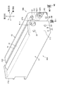
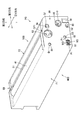
- FIG. 1 is a diagram showing a schematic configuration of a color printer according to an embodiment of the present invention. It is a perspective view which shows the color printer with the cover open.
- FIG. 3 is a perspective view showing the structure of one end of the first drum cartridge and the first developing cartridge in the first direction. It is a perspective view which shows the structure of the other end of the 1st drum cartridge and the 1st development cartridge in the 1st direction.
- FIG. 3 is a perspective view showing the structure of one end of the process cartridge in the first direction. It is a perspective view which shows the structure of the other end of the process cartridge in the 1st direction. It is a perspective view (a) and a side view (b) showing the structure around the 1st connector and the 2nd connector of a body case.
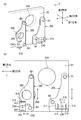
- FIG. (A) showing a state in which the first drum cartridge and the first developing cartridge are located at the first position in the third direction and the first developing cartridge is located at the contact position, and the first drum cartridge and the first developing cartridge. Is located at the first position in the third direction and the first developing cartridge is located at the separated position (b), and the first drum cartridge and the first developing cartridge are located at the second position in the third direction.
- FIG. (c) which shows the state which is positioned and the 1st development cartridge is located at a separated position.
- the color printer 1 includes a main body housing 2, a paper feeding unit 3, an image forming unit 4, and a paper discharging unit 21.
- the paper feeding unit 3 supplies the paper P to the image forming unit 4.
- the image forming unit 4 forms an image on the paper P.
- the paper ejection unit 21 ejects the paper P.
- the paper feeding unit 3 is located in the lower part of the main body housing 2.
- the paper feed unit 3 includes a paper feed tray 31 and a paper feed mechanism 32.
- the paper feed tray 31 is attachable to and detachable from the main body housing 2.
- the paper feed mechanism 32 conveys the paper P from the paper feed tray 31 to the image forming unit 4.
- the image forming unit 4 includes four first drum cartridges 40A, four first developing cartridges 50A, an exposure device SU, a transfer unit 60, and a fixing unit 70.
- the first drum cartridge 40A has a photosensitive drum 41, a drum frame F1, a drum memory M1, and a charger (not shown).
- the photosensitive drum 41 is rotatable about a first axis X1 extending in the first direction.
- the four first drum cartridges 40A are arranged in the first direction and the second direction orthogonal to the vertical direction.
- the drum memory M1 is a memory that stores drum information that is information about the photosensitive drum 41.
- the drum information can be, for example, information indicating the degree of deterioration of the photosensitive drum 41.
- the information indicating the degree of deterioration of the photosensitive drum 41 can be, for example, the total number of rotations of the photosensitive drum 41 corresponding to the predetermined first drum cartridge 40A.
- the control unit 100 which will be described later, for example, the number of revolutions of the “accumulated” photosensitive drum 41 stored in the memory of the printer body (cumulative number of revolutions) exceeds the total number of revolutions stored in the drum memory M1. At this time, it is determined that the photosensitive drum 41 has deteriorated.
- the first developing cartridge 50A has a developing roller 51, a developing case F2, and a developing memory M2.
- the developing case F2 contains toner.
- the developing roller 51 is rotatable about a second axis X2 extending in the first direction.
- the four first developing cartridges 50A are arranged in the second direction.
- the first developing cartridge 50A is aligned with the first drum cartridge 40A in the second direction.
- the development memory M2 is a memory that stores development information about the development roller 51 or toner.
- the development information can be, for example, information indicating the remaining amount of toner, information indicating the deterioration of the developing roller 51, or the like.
- the information indicating the remaining amount of toner can be, for example, the total number of printed sheets or the number of dot counts corresponding to the predetermined first developing cartridge 50A.
- the information indicating the deterioration of the developing roller 51 can be, for example, the total number of rotations of the developing roller 51 corresponding to the predetermined first developing cartridge 50A.
- the rotation speed (cumulative rotation speed) of the "cumulative" development roller 51 stored in the memory of the printer body exceeds the total rotation speed stored in the development memory M2. At this time, it is determined that the developing roller 51 has deteriorated.
- the exposure apparatus SU is located below each first drum cartridge 40A.
- the exposure device SU emits a laser beam to each photosensitive drum 41.
- the transfer unit 60 is located between the four photosensitive drums 41 and the paper output unit 21.
- the transfer unit 60 includes a drive roller 61, a driven roller 62, an intermediate transfer belt 63, four primary transfer rollers 64, and a secondary transfer roller 65.
- the intermediate transfer belt 63 is an endless belt.
- the intermediate transfer belt 63 is located above the first drum cartridge 40A and the first developing cartridge 50A when the first drum cartridge 40A and the first developing cartridge 50A are mounted in the main body housing 2.
- the primary transfer roller 64 is located inside the intermediate transfer belt 63.
- the primary transfer roller 64 and the photosensitive drum 41 sandwich the intermediate transfer belt 63.
- the secondary transfer roller 65 is located outside the intermediate transfer belt 63.
- the secondary transfer roller 65 and the drive roller 61 sandwich the intermediate transfer belt 63.
- the fixing unit 70 is located on the intermediate transfer belt 63.
- the fixing unit 70 includes a heating roller 71 and a pressure roller 72.
- the pressure roller 72 is pressed by the heating roller 71.
- the paper output unit 21 is located above the main body housing 2.
- the paper discharge unit 21 is located above the intermediate transfer belt 63.
- the paper discharge unit 21 includes a discharge roller 9 and a paper discharge surface 21A.
- the discharge roller 9 conveys the paper P toward the paper discharge surface 21A.
- the charger charges the surface of the photosensitive drum 41.
- the exposure device SU exposes the surface of the photosensitive drum 41.
- an electrostatic latent image is formed on the photosensitive drum 41.
- the developing roller 51 supplies toner to the electrostatic latent image on the photosensitive drum 41. As a result, a toner image is formed on the photosensitive drum 41. Then, the toner image on the photosensitive drum 41 is transferred onto the intermediate transfer belt 63.
- the toner image on the intermediate transfer belt 63 is transferred onto the paper P. After that, the toner image on the paper P is fixed by the fixing unit 70. Next, the paper P is discharged to the paper discharge surface 21A by the discharge roller 9.
- the main body housing 2 has an opening 22A.
- the color printer 1 includes a cover C.
- the cover C is a member for opening and closing the opening 22A.
- the first drum cartridge 40A can be attached to and detached from the main body housing 2 in the first direction through the opening 22A.
- the first developing cartridge 50A is attachable to and detachable from the main body housing 2 in the first direction through the opening 22A.
- the first drum cartridge 40A and the first developing cartridge 50A can be individually attached to and detached from the main body housing 2 in the first direction.
- the first drum cartridges 40A have the same structure.
- the first developing cartridges 50A have the same structure.
- Each first developing cartridge 50A contains toner of a different color.
- the main body housing 2 is also configured so that a process cartridge PC (see FIG. 5) described later can be attached and detached in the first direction. That is, the main body housing 2 allows the mounting and dismounting of the first drum cartridge 40A and the first developing cartridge 50A and also the mounting and dismounting of the process cartridge PC.
- a process cartridge PC see FIG. 5
- the main body housing 2, the first drum cartridge 40A, the first developing cartridge 50A, and the process cartridge PC constitute an image forming system.
- This image forming system is a system capable of configuring two types of color printers. That is, the first color printer can be configured by combining the main body housing 2, the first drum cartridge 40A, and the first developing cartridge 50A. Further, the second color printer can be configured by combining the main body housing 2 and the process cartridge PC.
- the drum frame F1 has a first drum outer surface F11 and a second drum outer surface F12.
- the first drum outer surface F11 is located at one end of the drum frame F1 in the first direction.
- the second drum outer surface F12 is located at the other end of the drum frame F1 in the first direction.
- the second drum outer surface F12 is spaced from the first drum outer surface F11 in the first direction.
- the second drum outer surface F12 is closer to the opening 22A (see FIG. 2) than the first drum outer surface F11 when the first drum cartridge 40A is mounted on the main body housing 2.
- the drum frame F1 further includes a first drum hole D1, a second drum hole D2, two holding protrusions P1, a drum coupling CP1, and a coupling hole F111.
- the first drum hole D1, the second drum hole D2, each holding protrusion P1, the drum coupling CP1 and the coupling hole F111 are located on the first drum outer surface F11.
- the first drum hole D1 and the second drum hole D2 are holes held by the main body housing 2.
- Each holding protrusion P1 is a protrusion that holds the drum memory M1.
- the holding protrusions P1 are arranged at intervals in the second direction.
- Each holding projection P1 sandwiches the drum memory M1 in the second direction.
- the drum memory F1 can be attached to the drum frame F1. Further, the drum memory M1 is located at one end of the drum frame F1 in the first direction in the state where the drum memory M1 is attached to the drum frame F1.
- the drum memory M1 has two first electrical contact surfaces M11.
- the two first electrical contact surfaces M11 are aligned in the second direction.
- the first electrical contact surface M11 comes into contact with the first connector CN1 (see FIG. 7), which will be described later, when the first drum cartridge 40A is mounted on the main body housing 2.
- the drum coupling CP1 is a coupling that receives a driving force from a driving source (not shown) arranged in the main body housing 2.
- the drum coupling CP1 is fixed to one end of the photosensitive drum 41.
- the drum coupling CP1 is located in the coupling hole F111.
- the developing case F2 has a first developing outer surface F21 and a second developing outer surface F22.
- the first development outer surface F21 is located at one end of the development housing F2 in the first direction.
- the second development outer surface F22 is located at the other end of the development housing F2 in the first direction.
- the second outer development surface F22 is located in the first direction with a space from the first outer development surface F21.
- the second developing outer surface F22 is closer to the opening 22A (see FIG. 2) than the first developing outer surface F21 when the first developing cartridge 50A is mounted in the main body housing 2.
- the developing housing F2 further includes a first developing hole G1, a second developing hole G2, two holding protrusions P2, a developing coupling CP2, and a coupling hole F211.
- the first developing hole G1, the second developing hole G2, each holding protrusion P2, the developing coupling CP2, and the coupling hole F211 are located on the first developing outer surface F21.
- the first developing hole G1 is a hole located inside the cylindrical boss.
- the tip surface of the boss forms a part of the first developed outer surface F21. That is, the first developed outer surface F21 has an uneven shape.
- the first developing hole G1 and the second developing hole G2 are holes held by the main body housing 2.
- Each holding protrusion P2 is a protrusion that holds the development memory M2.
- the holding protrusions P2 are arranged at intervals in the third direction orthogonal to the first direction and the second direction.
- the holding protrusions P2 sandwich the developing memory M2 in the third direction.
- the developing memory M2 can be attached to the developing housing F2. Further, the development memory M2 is located at one end of the development casing F2 in the first direction when attached to the development casing F2.
- the developing memory M2 has two second electrical contact surfaces M21.
- the two second electrical contact surfaces M21 are aligned in the third direction.
- the second electrical contact surface M21 comes into contact with the second connector CN2 (see FIG. 7), which will be described later, when the first developing cartridge 50A is mounted on the main body housing 2.
- the development coupling CP2 is a coupling that receives a driving force from a driving source (not shown) arranged in the main body housing 2.
- the development coupling CP2 is contained in the coupling hole F211.
- the driving force of the driving source is transmitted to the developing roller 51 via the developing coupling CP2.
- the drum frame F1 further includes a third drum hole D3, a fourth drum hole D4, and a drum handle H1.
- the third drum hole D3, the fourth drum hole D4, and the drum handle H1 are located on the second drum outer surface F12.
- the third drum hole D3 and the fourth drum hole D4 are holes held by the cover C.
- the fourth drum hole D4 is located on the outer surface of the drum handle H1.
- the outer surface of the drum handle H1 constitutes a part of the second drum outer surface F12. That is, the second drum outer surface F12 has an uneven shape.
- the drum handle H1 has a recess H11.
- the recess H11 allows the user's finger to be hooked when the user takes out the first drum cartridge 40A from the main body housing 2.
- the developing case F2 further includes a third developing hole G3, a fourth developing hole G4, and a developing handle H2.
- the third developing hole G3, the fourth developing hole G4, and the developing handle H2 are located on the second developing outer surface F22.
- the third developing hole G3 and the fourth developing hole G4 are holes held by the cover C.
- the third developing hole G3 is a hole located inside the cylindrical boss.
- the fourth developing hole G4 is formed in a rectangular boss.
- the tip surface of each boss constitutes a part of the second developed outer surface F22. That is, the second developed outer surface F22 has an uneven shape.
- the developing handle H2 has a recess H21.
- the recess H21 allows the user's finger to be hooked when the user takes out the first developing cartridge 50A from the main body housing 2.
- the process cartridge PC includes a second drum cartridge 40B, a second developing cartridge 50B, a first connecting cover 80 as an example of a connecting cover, and a second connecting cover 90.
- the second drum cartridge 40B has the same configuration as the first drum cartridge 40A (see FIG. 3) with the drum memory M1 removed. That is, the second drum cartridge 40B has the same photosensitive drum 41, drum frame F1 and drum coupling CP1 as the first drum cartridge 40A.
- the drum memory M1 is not attached to the drum frame F1 of the second drum cartridge 40B.
- the second developing cartridge 50B has the same configuration as the first developing cartridge 50A with the developing memory M2 removed. That is, the second developing cartridge 50B has the same developing roller 51, developing casing F2, and developing coupling CP2 as the first developing cartridge 50A.
- the development memory M2 is not attached to the development housing F2 of the second development cartridge 50B.
- the first connection cover 80 connects one end of the drum frame F1 in the first direction and one end of the developing housing F2 in the first direction.
- the second connection cover 90 connects the other end of the drum frame F1 in the first direction and the other end of the developing housing F2 in the first direction.
- the first connecting cover 80 and the second connecting cover 90 are fixed to the drum frame F1.
- the developing case F2 is supported by the first connecting cover 80 and the second connecting cover 90 so as to be movable in the second direction.
- the developing roller 51 comes into contact with the photosensitive drum 41 at a contact position (the position shown in FIG. 8A) and the developing roller 51 separates from the photosensitive drum 41 at a separated position (see FIG. 8B). ) Position) and is movable.
- the first connecting cover 80 includes a first hole 81, a second hole 82, a third hole 83, a first slot 84, a second slot 85, a third slot 86, and a holding hole 87. , A recess 88, and a process memory M3.
- the first hole 81 is a hole for exposing the first drum hole D1 of the second drum cartridge 40B to the outside.
- the second hole 82 is a hole for exposing the second drum hole D2 of the second drum cartridge 40B to the outside.
- the third hole 83 is a hole for exposing the drum coupling CP1 to the outside.
- the first elongated hole 84 is an elongated hole for exposing the first developing hole G1 of the second developing cartridge 50B to the outside when the second developing cartridge 50B is located at each position from the contact position to the separated position.
- the second elongated hole 85 is an elongated hole for exposing the second developing hole G2 of the second developing cartridge 50B to the outside when the second developing cartridge 50B is located at each position from the contact position to the separated position.
- the third slot 86 is a slot for exposing the development coupling CP2 to the outside when the second development cartridge 50B is located at each position between the contact position and the separation position.
- the length of the first elongated hole 84 in the second direction is longer than the length of the first elongated hole 84 in the third direction. Further, the length of the second long hole 85 in the second direction is longer than the length of the second long hole 85 in the third direction. Furthermore, the length of the third elongated hole 86 in the second direction is longer than the length of the third elongated hole 86 in the third direction.
- the holding hole 87 is a hole for holding the process memory M3.
- the holding hole 87 is a rectangular hole. One end and the other end of the holding hole 87 in the third direction sandwich the process memory M3 in the third direction.
- Each holding protrusion P1 of the drum frame F1 passes through the holding hole 87 and projects outward from the first connecting cover 80.
- Each holding protrusion P1 is located at both ends of the holding hole 87 in the second direction.
- Each holding projection P1 sandwiches the process memory M3 in the second direction.
- the process memory M3 is a memory that stores the drum information and the development information described above.
- the process memory M3 has two third electrical contact surfaces M31.
- the two third electrical contact surfaces M31 are arranged in the second direction.
- the third electrical contact surface M31 is connected when the process cartridge PC is attached to the main body housing 2, that is, the second drum cartridge 40B and the second developing cartridge 50B are connected by the first connecting cover 80 and the second connecting cover 90.
- a first connector CN1 see FIG. 7 described later.
- the recess 88 is recessed in the first direction.
- the recess 88 covers the second connector CN2 when the process cartridge PC is mounted on the main body housing 2 and the third electrical contact surface M31 comes into contact with the first connector CN1.
- the recess 88 is located away from the second connector CN2 in the first direction when the process cartridge PC is mounted on the main body housing 2 and the third electrical contact surface M31 contacts the first connector CN1. ..
- the length of the recess 88 in the second direction is longer than the moving range of the second connector CN2 that moves together with the second developing cartridge 50B.
- the second connection cover 90 has a first hole 91, a second hole 92, a first long hole 93, and a second long hole 94.
- the first hole 91 is a hole for exposing the third drum hole D3 of the second drum cartridge 40B to the outside.
- the second hole 92 is a hole for exposing the other end of the photosensitive drum 41 to the outside.
- the first elongated hole 93 is a hole for exposing the third developing hole G3 of the second developing cartridge 50B to the outside when the second developing cartridge 50B is located at each position from the contact position to the separated position. is there.
- the second elongated hole 94 is a hole for exposing the fourth developing hole G4 of the second developing cartridge 50B to the outside when the second developing cartridge 50B is located at each position from the contact position to the separated position. is there.
- the length of the first elongated hole 93 in the second direction is longer than the length of the first elongated hole 93 in the third direction.
- the length of the second elongated hole 94 in the second direction is longer than the length of the second elongated hole 94 in the third direction.
- the main body housing 2 includes a side wall 23, a first holder 200, and a second holder 300.
- the side wall 23 constitutes the side wall of the main body housing 2.
- the side wall 23 faces the opening 22A (see FIG. 2) in the first direction.
- the side wall 23 has a first through hole 23A and a second through hole 23B.
- the first through hole 23A is a hole through which a first main body coupling (not shown) that applies a driving force to the drum coupling CP1 passes.
- the first body coupling is movable in the first direction between a first connection position connected to the drum coupling CP1 and a first retracted position separated from the drum coupling CP1.
- the second through hole 23B is a hole through which a second main body coupling (not shown) that gives a driving force to the developing coupling CP2 passes.
- the second main body coupling is movable in the first direction between a second connection position connected to the development coupling CP2 and a second retracted position away from the development coupling CP2.
- the first holder 200 is supported by the side wall 23 so as to be movable in the third direction.
- the first holder 200 has a first main body protrusion B1, a second main body protrusion B2, and a first holding portion 210.
- the first main body protrusion B1 is a protrusion that fits into the first drum hole D1 of the drum frame F1 when the first drum cartridge 40A or the process cartridge PC is mounted on the main body housing 2.
- the second main body protrusion B2 is a protrusion that fits into the second drum hole D2 of the drum frame F1 when the first drum cartridge 40A or the process cartridge PC is mounted on the main body housing 2.
- the first holding part 210 is a part for holding the two first connectors CN1. Each first connector CN1 is connected to the control unit 100 described later. Each first connector CN1 is arranged in the second direction.
- the first holding part 210 has two holding holes 211, two engaging holes 212, and two support walls 213.
- the holding hole 211 is a hole for holding the first connector CN1.
- the holding holes 211 are arranged in the second direction. Each holding hole 211 is located between the engaging holes 212 in the second direction.
- the respective engagement holes 212 are holes into which the respective holding projections P1 of the drum frame F1 are inserted when the first drum cartridge 40A or the process cartridge PC is mounted on the main body housing 2.
- Each engagement hole 212 is located between each support wall 213 in the second direction.
- Each support wall 213 is a wall that guides each holding projection P1 in the first direction.
- the first holder 200 configured as described above includes the first drum cartridge 40A, the first drum cartridge 40A, and the first connector CN1 in the state where the first drum cartridge 40A is attached to the main body casing 2, It can be moved in any direction. Further, in the state where the process cartridge PC is mounted on the main body housing 2, the first holder 200 moves in the third direction together with the process cartridge PC (second drum cartridge 40B) and the first connector CN1 with respect to the main body housing 2. It is movable.
- the second holder 300 is supported by the side wall 23 so as to be movable in the second direction and the third direction.
- the second holder 300 has a third body protrusion B3, a fourth body protrusion B4, a second holding portion 310, and a through hole 320.
- the third main body protrusion B3 is a protrusion that fits into the first developing hole G1 of the developing casing F2 when the first developing cartridge 50A or the process cartridge PC is mounted in the main casing 2.
- the fourth main body protrusion B4 is a protrusion that fits into the second developing hole G2 of the developing housing F2 when the first developing cartridge 50A or the process cartridge PC is mounted in the main housing 2.
- the second holding portion 310 is a portion for holding the two second connectors CN2.
- Each second connector CN2 is connected to the control unit 100 described later.
- the second connectors CN2 are arranged in the third direction.
- the second holding portion 310 has two holding holes 311 and two engaging holes 312 and two support walls 313.
- the holding hole 311 is a hole for holding the second connector CN2.
- the holding holes 311 are arranged in the third direction. Each holding hole 311 is located between the engaging holes 312 in the third direction.
- Each engaging hole 312 is a hole into which each holding projection P2 of the developing housing F2 is inserted when the first developing cartridge 50A is mounted on the main body housing 2.
- Each engagement hole 312 is located between each support wall 313 in the third direction.
- Each support wall 313 is a wall that guides each holding projection P2 in the first direction.
- the second holding portion 310 is covered with the recess 88 of the first connection cover 80 when the process cartridge PC is mounted in the main body housing 2. Further, the second holding portion 310 is movable in the recess 88 together with the second holder 300 in the second direction and the third direction.
- the through hole 320 is a hole through which the above-mentioned second main body coupling passes.
- the through hole 320 is located at a position corresponding to the development coupling CP2.
- the second holder 300 having the above-described structure is provided with the second developing cartridge 50A and the second connector CN2 together with the second developing cartridge 50A with respect to the main body housing 2 when the first developing cartridge 50A is mounted on the main body housing 2.
- Direction and the third direction Further, the second holder 300 is movable in the second direction and the third direction together with the second developing cartridge 50B with respect to the main body housing 2 when the process cartridge PC is mounted in the main body housing 2. ..
- the cover C (see FIG. 2) includes a first holder 200 and a second holder 300.
- the first holder 200 of the cover C does not have the first connector CN1 and the first holding portion 210.
- the second holder 300 of the cover C does not have the second connector CN2 and the second holding portion 310.
- the first holder 200 of the cover C appropriately has a main body protrusion that fits into the third drum hole D3 and the fourth drum hole D4 located at the other end of the drum frame F1.
- the second holder 300 of the cover C appropriately has a main body protrusion that fits into the third developing hole G3 and the fourth developing hole G4 located at the other end of the developing housing F2.
- both ends of the drum frame F1 in the first direction are supported by the first holder 200 of the side wall 23 and the first holder 200 of the cover C.
- the drum frame F1 and each first holder 200 are movable with respect to the side wall 23 and the cover C.
- both ends of the developing case F2 in the first direction are supported by the second holder 300 of the side wall 23 and the second holder 300 of the cover C.
- the developing housing F2 and each second holder 300 are movable with respect to the side wall 23 and the cover C.
- the first drum cartridge 40A and the first developing cartridge 50A are both movable between the first position and the second position in the third direction.
- the photosensitive drum 41 contacts the intermediate transfer belt 63.
- the photosensitive drum 41 is separated from the intermediate transfer belt 63.
- the positional relationship between the photosensitive drum 41 and the developing roller 51 in the third direction does not change at both the first position and the second position.
- the first developing cartridge 50A When the first developing cartridge 50A is located at the first position, it moves in the second direction between the contact position and the separated position described above.
- the first drum cartridge 40A and the first developing cartridge 50A are attached to the main body housing 2, as shown in FIG. 8C, the first drum cartridge 40A and the first developing cartridge 50A are both moved in the third direction. It is located at the second position, and the first developing cartridge 50A is located at the separated position.
- the first drum cartridge 40A and the first developing cartridge 50A move together to the first position shown in FIG. 8B. Thereafter, the first developing cartridge 50A moves in the second direction from the separated position shown in FIG. 8(b) to the contact position shown in FIG. 8(a).
- the first developing cartridge 50A first moves in the second direction from the contact position shown in FIG. 8A to the separation position shown in FIG. 8B. After that, the first drum cartridge 40A and the first developing cartridge 50A move together from the first position shown in FIG. 8B to the second position shown in FIG. 8C.
- the main body housing 2 further includes a control unit 100, a main body memory M4, and a display DS.
- the control unit 100 includes a CPU, a RAM, a ROM, and an input / output circuit, and executes control by performing various arithmetic processes based on programs and data stored in the ROM or the like.
- the main body memory M4 stores a drum exchange message, a development exchange message, and a process exchange message.
- the drum replacement message is a message for prompting replacement of the first drum cartridge 40A when the first drum cartridge 40A and the first developing cartridge 50A are mounted in the main body housing 2.
- the development exchange message is a message for prompting the exchange of the first development cartridge 50A in a state where the first drum cartridge 40A and the first development cartridge 50A are mounted on the main body housing 2.
- the process replacement message is a message for prompting replacement of the process cartridge PC when the process cartridge PC is mounted in the main body housing 2.
- the main body memory M4 stores the first print permission information and the second print permission information.
- the first print permission information is information indicating that printing is possible only when the first drum cartridge 40A and the first development cartridge 50A are mounted on the main body housing 2.
- the second print permission information is information indicating that printing is possible only when the process cartridge PC is mounted on the main body housing 2.
- both the first print permission information and the second print permission information are stored in the main body memory M4, so that the first drum cartridge 40A and the first developing cartridge 50A are mounted and the process cartridge PC. It is possible to print in both cases when is attached.
- the first print permission information has first identification information corresponding to the first drum cartridge 40A and the first developing cartridge 50A.
- the second print permission information has second identification information corresponding to the process cartridge PC.
- the drum memory M1 stores the first identification information.
- the development memory M2 stores the first identification information.
- the process memory M3 stores the second identification information.
- the control unit 100 determines whether the identification information acquired from the first connector CN1 or the second connector CN2 matches the first identification information or the second identification information stored in the main body memory M4. When the control unit 100 determines that the identification information acquired from the connectors CN1 and CN2 matches the first identification information stored in the main body memory M4, the control unit 100 determines the first drum cartridge 40A and the first drum cartridge 40A based on the first print permission information. The first print control suitable for the first development cartridge 50A is executed. When the control unit 100 determines that the identification information acquired from the connectors CN1 and CN2 matches the second identification information stored in the main body memory M4, the control unit 100 sets the process cartridge PC based on the second print permission information. A suitable second print control is executed.
- the control unit 100 determines the replacement timing of at least one of the first drum cartridge 40A and the first developing cartridge 50A based on the information stored in the drum memory M1 and the developing memory M2. judge.
- the control unit 100 determines the replacement timing of the process cartridge PC based on the information in the process memory M3.
- Display DS is a device that displays the above-mentioned exchange message and the like.
- the control unit 100 determines that it is the replacement timing of at least one of the first drum cartridge 40A, the first developing cartridge 50A, and the process cartridge PC, the control unit 100 displays the replacement message corresponding to the cartridge that needs to be replaced on the display DS. Let me know.
- control unit 100 constantly repeatedly executes the processing shown in FIG.
- control unit 100 first determines whether or not there is a print command (S1). When it is determined in step S1 that there is no print command (No), the control unit 100 ends this process.
- step S1 When it is determined in step S1 that there is a print command (Yes), the control unit 100 determines whether information can be acquired from the first connector CN1 (S2). Specifically, in step S2, the control unit 100 determines whether the identification information acquired from the first connector CN1 is the first identification information or the second identification information, and thus the first electrical contact surface M11 or the first electrical contact surface M11. 3 It is determined whether the electrical contact surface M31 is in contact with the first connector CN1.
- step S2 When it is determined in step S2 that the information could not be acquired from the first connector CN1 (No), the control unit 100 determines that the first drum cartridge 40A or the process cartridge PC is not mounted in the main body housing 2. Then, the error is notified (S3).
- step S4 the control unit 100 determines that the cartridge mounted in the main body housing 2 is based on the information acquired from the first connector CN1. It is determined whether or not it is a process cartridge PC (S4). Specifically, in step S4, the control unit 100 determines whether or not the identification information acquired from the first connector CN1 is the second identification information, and thus the third electrical contact surface M31 and the first connector CN1. Is in contact with each other, and it is determined whether or not the process cartridge PC is mounted on the main body housing 2. The process of step S4 corresponds to the cartridge determination process.
- step S4 When it is determined in step S4 that the cartridge mounted on the main body housing 2 is not a process cartridge PC (No), the control unit 100 determines whether or not information can be acquired from the second connector CN2 (S5). .. In other words, the control unit 100 determines whether or not the identification information acquired from the second connector CN2 is the first identification information in step S5, so that the second electrical contact surface M21 is the second connector CN2. It is determined whether or not it is in contact with.
- step S5 When it is determined in step S5 that the information could not be acquired from the second connector CN2 (No), the control unit 100 determines that the first developing cartridge 50A is not attached to the main body housing 2, and an error message Notify (S6).
- step S6 When it is determined in step S5 that the information can be acquired from the second connector CN2 (Yes), the control unit 100 determines that the first drum cartridge 40A and the first developing cartridge 50A are attached to the main body housing 2. That is, in the control unit 100, the first electrical contact surface M11 contacts the first connector CN1 (S2: Yes, step S4: No), and the second electrical contact surface M21 contacts the second connector CN2. In this case (S5: Yes), it is determined that the first drum cartridge 40A and the first developing cartridge 50A are mounted in the main body housing 2.
- the processes of steps S2, S4 and S5 correspond to the cartridge determination process.
- the control unit 100 determines whether the first print permission information is stored in the main body memory M4. Is determined (S7). When it is determined in step S7 that the first print permission information is not stored (No), the control unit 100 ends this processing.
- step S7 When it is determined in step S7 that the first print permission information is stored (Yes), the control unit 100 executes print processing (S8). After step S8, the control unit 100 executes a drum replacement determination process that determines whether it is the replacement timing of the first drum cartridge 40A based on the drum information in the drum memory M1 (S9).
- step S9 When it is determined in step S9 that it is time to replace the first drum cartridge 40A (Yes), the control unit 100 displays a drum replacement message on the display DS (S10). When it is determined in step S9 that it is not the replacement timing of the first drum cartridge 40A (No), the control unit 100 determines whether it is the replacement timing of the first developing cartridge 50A based on the development information in the development memory M2. A development replacement determination process is performed (S11).
- step S11 If it is determined in step S11 that it is time to replace the first development cartridge 50A (Yes), the control unit 100 displays a development replacement message on the display DS (S12). When it is determined in step S11 that it is not the replacement timing of the first developing cartridge 50A (No), the control unit 100 ends this processing.
- step S4 If it is determined in step S4 that the process cartridge PC is mounted in the main body housing 2 (Yes), the control unit 100 determines whether or not the second print permission information is stored in the main body memory M4 (S13). ). When it is determined in step S13 that the second print permission information is not stored (No), the control unit 100 ends this processing.
- step S13 When it is determined in step S13 that the second print permission information is stored (Yes), the control unit 100 executes print processing (S14). After step S14, the control unit 100 determines whether it is the replacement timing of the process cartridge PC (S15).
- step S15 the control unit 100 executes a drum replacement determination process and a development replacement determination process.
- the drum replacement determination process of step S15 the control unit 100 determines whether it is the replacement timing of the second drum cartridge 40B based on the drum information of the process memory M3.
- the development replacement determination process of step S15 the control unit 100 determines whether or not it is the replacement timing of the second development cartridge 50B based on the development information of the process memory M3.
- step S15 when the control unit 100 determines that the second drum cartridge 40B or the second development cartridge 50B is the replacement timing, it determines that the process cartridge PC is the replacement timing. Further, in step S15, if it is determined that neither the second drum cartridge 40B nor the second developing cartridge 50B is the replacement timing, the control unit 100 determines that it is not the replacement timing of the process cartridge PC.
- step S15 If it is determined in step S15 that it is time to replace the process cartridge PC (Yes), the control unit 100 displays a process replacement message on the display DS (S16). When it is determined in step S15 that it is not the replacement timing of the process cartridge PC (No), the control unit 100 ends this processing.
- step S1 Yes ⁇ S2: Yes ⁇ S4: of FIG.
- the control unit 100 determines Yes in step S7 and executes the print process (S8). After the printing process ends, the control unit 100 determines the replacement timing of each cartridge based on the drum information of the drum memory M1 and the development information of the development memory M2 (S9, S11).
- the control unit 100 executes the process in the order of step S1: Yes ⁇ S2: Yes ⁇ S4: Yes in FIG. 9 when receiving a print command. Then, it is determined that the process cartridge PC is mounted in the main body housing 2.
- the control unit 100 determines Yes in step S13 and executes the print process (S14). After the printing process is completed, the control unit 100 determines the replacement timing of the process cartridge PC based on the drum information and the development information in the process memory M3 (S15).
- the process cartridge PC which is an integrated type cartridge
- the third electrical contact surface M31 of the process memory M3 comes into contact with the first connector CN1 for the first drum cartridge 40A, which is a separation type cartridge. Therefore, both types of cartridges can be used in the common main body housing 2. Further, even when the main body casing 2 is designed for the separation type cartridge, the integral type cartridge can be attached to and detached from the main body casing 2 without changing the design of the main body casing 2. As a result, the cost for designing the main body housing 2 can be suppressed.
- first connection cover 80 Since the first connection cover 80 has the recess 88, it is possible to prevent the first connection cover 80 from interfering with the second connector CN2 when the process cartridge PC is mounted in the main body housing 2.
- both the integrated process cartridge PC and the separation type first drum cartridge 40A and the first development cartridge 50A can be used in the common main body housing 2 (printing process).
- the present invention is not limited to this.
- only the separation type first drum cartridge 40A and the first development cartridge 50A may be used in the main body housing 2, and the integrated process cartridge PC may not be usable in the main body housing 2.
- the main body memory M4 may be configured to store the first identification information and not the second identification information.
- the control unit 100 determines. In step S7, Yes is determined and printing is executed. Further, in the cartridge determination process in step S4 of FIG. 9, when it is determined that the process cartridge PC is mounted in the main body housing 2, the control unit 100 determines No in step S13 and does not execute printing.
- the separation type first drum cartridge 40A and the first developing cartridge 50A may be made unusable in the main body housing 2, and the integral type process cartridge PC may be made usable in the main body housing 2. ..
- the main body memory M4 may be configured to store the second identification information and not the first identification information.
- the control unit 100 determines Yes in step S13, and executes printing.
- the present invention is not limited to this. For example, even if the third electrical contact surface is brought into contact with the second connector. Good.
- the exchange message is notified to the user by displaying the exchange message on the display DS, but the present disclosure is not limited to this, and for example, the exchange message may be notified by a speaker. ..
- the first connector CN1 is movable in the third direction and the second connector CN2 is movable in the second direction and the third direction, but the present disclosure is not limited to this.
- the first connector may be fixed to the main body housing and the second connector may be movable in the second direction.
- the first drum cartridge 40A and the first developing cartridge 50A are mounted on the main body housing 2, the first drum cartridge 40A is located at the position shown in FIG. 8C, whereas the first developing cartridge is located.
- 50A is located at the position shown in FIG.
- the first connector may be movable in the third direction and the second connector may be movable in the second direction. Further, for example, when the first drum cartridge 40A and the first developing cartridge 50A are mounted on the main body housing 2, the first drum cartridge 40A is located at the position shown in FIG. 8C, whereas the first developing cartridge is located. When 50A is located at the position of FIG. 8A, the first connector may be movable in the third direction and the second connector may be fixed to the main body housing.
- the present invention is applied to the color printer 1, but the present invention is not limited to this, and the present invention is applied to other image forming apparatuses such as a monochrome printer, a copying machine, and a multifunction machine. Good.
Landscapes
- Physics & Mathematics (AREA)
- General Physics & Mathematics (AREA)
- Engineering & Computer Science (AREA)
- Computer Vision & Pattern Recognition (AREA)
- Electrophotography Configuration And Component (AREA)
- Dry Development In Electrophotography (AREA)
- Control Or Security For Electrophotography (AREA)
- Discharging, Photosensitive Material Shape In Electrophotography (AREA)
Abstract
分離方式・一体方式のカートリッジの両方を本体筐体に着脱可能にすることを目的とする。画像形成装置は、第1電気的接触面を有するドラムメモリを有する第1ドラムカートリッジと、第2電気的接触面を有する現像メモリを有する第1現像カートリッジとが、感光ドラムの回転軸に沿った第1方向に装着されること、または、第3電気的接触面を有するプロセスメモリを有する連結カバーに連結されたカートリッジが第1方向に装着されることを許容する本体筐体2を備える。本体筐体2は、第1ドラムカートリッジが本体筐体に装着された場合に第1電気的接触面と接触する第1コネクタCN1と、第1現像カートリッジが本体筐体2に装着された場合に第2電気的接触面と接触する第2コネクタCN2を有する。第3電気的接触面は、連結カバーで連結されたカートリッジが本体筐体2に装着された場合に第1コネクタCN1と接触する。
Description
本開示は、ドラムカートリッジおよび現像カートリッジを備える画像形成装置に関する。
従来、本体筐体に対してドラムカートリッジおよび現像カートリッジを感光ドラムの軸方向に着脱可能な画像形成装置が知られている(特許文献1参照)。この技術では、ドラムカートリッジおよび現像カートリッジは、それぞれ本体筐体に対して個別に着脱可能となっている。
ところで、従来のようなドラムカートリッジおよび現像カートリッジのそれぞれに、ICチップ(メモリ)を備えることが望まれている。ドラムカートリッジのドラムICチップ(ドラムメモリ)は、ドラムカートリッジに関する情報を記憶している。一方、現像カートリッジの現像ICチップ(現像メモリ)は、現像カートリッジの情報を記憶している。本体筐体にドラムカートリッジおよび現像カートリッジが装着された状態において、本体筐体は、ドラムICチップからドラムカートリッジの情報を読み取るとともに、現像ICチップから現像カートリッジの情報を読み取る。
また、従来のようなドラムカートリッジおよび現像カートリッジをそれぞれ個別に着脱可能な本体筐体に、ドラムカートリッジおよび現像カートリッジを一体化した一体方式カートリッジを着脱可能することも望まれている。
つまり、ドラムカートリッジの情報を記憶したドラムICチップを有するドラムカートリッジおよび現像カートリッジの情報を記憶した現像ICチップを有する現像カートリッジをそれぞれ個別に着脱可能な本体筐体に、ドラムカートリッジおよび現像カートリッジを一体化した一体方式カートリッジであって、ドラムカートリッジの情報および現像カートリッジの情報を記憶したICチップを有する一体方式カートリッジを着脱可能にすることも望まれている。
また、従来のようなドラムカートリッジおよび現像カートリッジをそれぞれ個別に着脱可能な本体筐体に、ドラムカートリッジおよび現像カートリッジを一体化した一体方式カートリッジを着脱可能することも望まれている。
つまり、ドラムカートリッジの情報を記憶したドラムICチップを有するドラムカートリッジおよび現像カートリッジの情報を記憶した現像ICチップを有する現像カートリッジをそれぞれ個別に着脱可能な本体筐体に、ドラムカートリッジおよび現像カートリッジを一体化した一体方式カートリッジであって、ドラムカートリッジの情報および現像カートリッジの情報を記憶したICチップを有する一体方式カートリッジを着脱可能にすることも望まれている。
そこで、本開示は、ドラムカートリッジの情報を記憶したドラムICチップを有するドラムカートリッジおよび現像カートリッジの情報を記憶した現像ICチップを有する現像カートリッジをそれぞれ個別に着脱可能な本体筐体に、ドラムカートリッジおよび現像カートリッジを一体化した一体方式カートリッジであって、ドラムカートリッジの情報および現像カートリッジの情報を記憶したICチップを有する一体方式カートリッジを着脱可能にすることを目的とする。
前記課題を解決するため、本発明に係る画像形成装置は、第1方向に延びる第1軸について回転可能な感光ドラムと、前記感光ドラムに関する情報であるドラム情報を記憶するドラムメモリであって、第1電気的接触面を有するドラムメモリと、を有する第1ドラムカートリッジと、前記第1方向に延びる第2軸について回転可能な現像ローラと、トナーを収容する現像筐体と、前記現像ローラまたは前記トナーに関する現像情報を記憶する現像メモリであって、第2電気的接触面を有する現像メモリと、を有する第1現像カートリッジとが、前記第1方向に装着されること、または、前記感光ドラムを有する第2ドラムカートリッジ、および、前記現像ローラと前記現像筐体とを有する第2現像カートリッジが、前記ドラム情報および前記現像情報を記憶するプロセスメモリであって、第3電気的接触面を有するプロセスメモリを有する連結カバーに連結された状態で、前記第1方向に装着されること、を許容する本体筐体を備える。
前記本体筐体は、前記第1ドラムカートリッジが前記本体筐体に装着された場合に、前記第1電気的接触面と接触する第1コネクタと、前記第1現像カートリッジが前記本体筐体に装着された場合に、前記第2電気的接触面と接触する第2コネクタと、を有する。
前記第3電気的接触面は、前記第2ドラムカートリッジと前記第2現像カートリッジが前記連結カバーで連結された状態で前記本体筐体に装着された場合に、前記第1コネクタまたは前記第2コネクタと接触する。
前記本体筐体は、前記第1ドラムカートリッジが前記本体筐体に装着された場合に、前記第1電気的接触面と接触する第1コネクタと、前記第1現像カートリッジが前記本体筐体に装着された場合に、前記第2電気的接触面と接触する第2コネクタと、を有する。
前記第3電気的接触面は、前記第2ドラムカートリッジと前記第2現像カートリッジが前記連結カバーで連結された状態で前記本体筐体に装着された場合に、前記第1コネクタまたは前記第2コネクタと接触する。
この構成によれば、連結カバーで連結された第2ドラムカートリッジおよび第2現像カートリッジ、つまり一体方式のカートリッジを本体筐体に装着すると、プロセスメモリの第3電気的接触面が、分離方式のカートリッジ用のコネクタである第1コネクタまたは第2コネクタと接触するので、どちらの方式のカートリッジであっても共通の本体筐体で使用可能とすることができる。また、分離方式のカートリッジ用に本体筐体を設計した場合であっても、本体筐体の設計変更することなく、本体筐体に一体方式のカートリッジを着脱可能にすることができるので、本体筐体の設計にかかるコストを抑えることができる。
また、前記第3電気的接触面は、前記第2ドラムカートリッジと前記第2現像カートリッジが前記連結カバーで連結された状態で前記本体筐体に装着された場合に、前記第1コネクタと接触してもよい。
また、前記連結カバーは、前記第2ドラムカートリッジと前記第2現像カートリッジが前記連結カバーで連結された状態で前記本体筐体に装着され、前記第3電気的接触面が前記第1コネクタと接触した場合に、前記第1方向において前記第2コネクタと離れて位置していてもよい。
これによれば、連結カバーで連結された第2ドラムカートリッジおよび第2現像カートリッジを本体筐体に装着する際に、連結カバーが第2コネクタと干渉するのを抑制することができる。
また、前記連結カバーは、前記第1方向に凹む凹部であって、前記第2ドラムカートリッジと前記第2現像カートリッジが前記連結カバーで連結された状態で前記本体筐体に装着され、前記第3電気的接触面が前記第1コネクタと接触した場合に、前記第2コネクタを覆う凹部を有していてもよい。
これによれば、連結カバーが第2コネクタと干渉するのをより良好に抑制することができる。
また、前記第1ドラムカートリッジおよび前記第2ドラムカートリッジは、前記ドラムメモリを取り付け可能なドラムフレームを有し、前記ドラムメモリは、前記第1方向における前記第1ドラムカートリッジの前記ドラムフレームの一端部に位置し、前記現像メモリは、前記第1方向における前記第1現像カートリッジの前記現像筐体の一端部に位置し、前記連結カバーは、前記第1方向における前記ドラムフレームの前記一端部と前記第1方向における前記現像筐体の前記一端部を連結してもよい。
また、前記ドラムメモリは、前記第2ドラムカートリッジの前記ドラムフレームに取り付けられておらず、前記現像メモリは、前記第2現像カートリッジの前記現像筐体に取り付けられていなくてもよい。
また、前記本体筐体は、制御部を有し、前記制御部は、前記第1電気的接触面と前記第1コネクタが接触し、前記第2電気的接触面と前記第2コネクタが接触している場合に、前記第1ドラムカートリッジと前記第1現像カートリッジが前記本体筐体に装着されたと判定し、前記第3電気的接触面と前記第1コネクタまたは前記第2コネクタが接触している場合に、前記第2ドラムカートリッジと前記第2現像カートリッジが前記連結カバーで連結されている状態で前記本体筐体に装着されたと判定するカートリッジ判定処理を実行可能であってもよい。
また、前記制御部は、前記第1ドラムカートリッジまたは前記第2ドラムカートリッジの交換タイミングか否かを判定するドラム交換判定処理と、前記第1現像カートリッジまたは前記第2現像カートリッジの交換タイミングか否かを判定する現像交換判定処理と、を実行可能であってもよい。
また、前記画像形成装置は、ディスプレイまたはスピーカーを備え、前記制御部は、前記カートリッジ判定処理において、前記第1ドラムカートリッジと前記第1現像カートリッジが前記本体筐体に装着されたと判定した場合であって、前記ドラム交換判定処理において、前記第1ドラムカートリッジの交換タイミングであると判定した場合に、前記ディスプレイまたはスピーカーに前記第1ドラムカートリッジの交換タイミングであることを示すドラム交換メッセージを報知させ、前記カートリッジ判定処理において、前記第1ドラムカートリッジと前記第1現像カートリッジが前記本体筐体に装着されたと判定した場合であって、前記現像交換判定処理において、前記第1現像カートリッジの交換タイミングであると判定した場合に、前記ディスプレイまたはスピーカーに前記第1現像カートリッジの交換タイミングであることを示す現像交換メッセージを報知させ、前記カートリッジ判定処理において、前記第2ドラムカートリッジと前記第2現像カートリッジが前記連結カバーで連結された状態で前記本体筐体に装着されたと判定した場合であって、前記ドラム交換判定処理において、前記第2ドラムカートリッジの交換タイミングであると判定された場合、または、前記現像交換判定処理において、前記第2現像カートリッジの交換タイミングであると判定された場合に、前記ディスプレイまたはスピーカーに前記第2ドラムカートリッジおよび前記第2現像カートリッジの交換タイミングであることを示すプロセス交換メッセージを報知させてもよい。
また、前記本体筐体は、前記ドラム交換メッセージと、前記現像交換メッセージと、前記プロセス交換メッセージと、を記憶する本体メモリを有していてもよい。
また、前記本体筐体は、前記第1ドラムカートリッジと前記第1現像カートリッジが前記本体筐体に装着された場合にのみ印刷可能であることを示す第1印刷許可情報、または、前記第2ドラムカートリッジおよび前記第2現像カートリッジが前記連結カバーに連結されている状態で前記本体筐体に装着された場合にのみ印刷可能であることを示す第2印刷許可情報を記憶する本体メモリを有し、前記制御部は、前記本体メモリに、前記第1印刷許可情報が記憶され、かつ、前記第2印刷許可情報が記憶されていない場合であって、前記カートリッジ判定処理において、前記第1ドラムカートリッジおよび前記第1現像カートリッジが前記本体筐体に装着されたと判定した場合、印刷を実行し、前記本体メモリに、前記第1印刷許可情報が記憶され、かつ、前記第2印刷許可情報が記憶されていない場合であって、前記カートリッジ判定処理において、前記第2ドラムカートリッジおよび前記第2現像カートリッジが前記連結カバーに連結された状態で前記本体筐体に装着されたと判定した場合、印刷を実行せず、前記本体メモリに、前記第2印刷許可情報が記憶され、かつ、前記第1印刷許可情報が記憶されていない場合であって、前記カートリッジ判定処理において、前記第1ドラムカートリッジおよび前記第1現像カートリッジが前記本体筐体に装着されたと判定した場合、印刷を実行せず、前記本体メモリに、前記第2印刷許可情報が記憶され、かつ、前記第1印刷許可情報が記憶されていない場合であって、前記カートリッジ判定処理において、前記第2ドラムカートリッジおよび前記第2現像カートリッジが前記連結カバーで連結された状態で前記本体筐体に装着されたと判定した場合、印刷を実行してもよい。
また、前記本体筐体は、前記第1コネクタを保持する第1ホルダであって、前記第1ドラムカートリッジが前記本体筐体に装着された状態において、前記本体筐体に対して前記第1ドラムカートリッジおよび前記第1コネクタとともに移動可能な第1ホルダを備えていてもよい。
また、前記本体筐体は、前記第2コネクタを保持する第2ホルダであって、前記第1現像カートリッジが前記本体筐体に装着された状態において、前記本体筐体に対して前記第1現像カートリッジおよび前記第2コネクタとともに移動可能な第2ホルダを備えていてもよい。
また、前記第1ドラムカートリッジおよび前記第1現像カートリッジは、前記本体筐体にそれぞれ個別に着脱可能であってもよい。
また、前記第1ドラムカートリッジおよび前記第1現像カートリッジが前記本体筐体に装着された状態において、前記第1ドラムカートリッジおよび前記第1現像カートリッジよりも上方に位置する中間転写ベルトと、用紙を排紙するための排紙部であって、前記中間転写ベルトよりも上方に位置する排紙部と、を備えていてもよい。
本発明によれば、ドラムメモリを有するドラムカートリッジおよび現像メモリを有する現像カートリッジをそれぞれ個別に着脱可能な本体筐体に、ドラムカートリッジおよび現像カートリッジを一体化した一体方式カートリッジであって、プロセスメモリを有する一体方式カートリッジを着脱可能にすることができる。
次に、本開示の一実施形態について、適宜図面を参照しながら詳細に説明する。なお、以下の説明においては、まず、画像形成装置の一例としてのカラープリンタ1の全体構成を説明する。
図1に示すように、カラープリンタ1は、本体筐体2と、給紙部3と、画像形成部4と、排紙部21と、を備える。給紙部3は、画像形成部4に用紙Pを供給する。画像形成部4は、用紙Pに画像を形成する。排紙部21は、用紙Pを排紙する。
給紙部3は、本体筐体2内の下部に位置する。給紙部3は、給紙トレイ31と、給紙機構32と、を備える。給紙トレイ31は、本体筐体2に着脱可能である。給紙機構32は、用紙Pを給紙トレイ31から画像形成部4に搬送する。
画像形成部4は、4つの第1ドラムカートリッジ40Aと、4つの第1現像カートリッジ50Aと、露光装置SUと、転写ユニット60と、定着ユニット70と、を備える。
第1ドラムカートリッジ40Aは、感光ドラム41と、ドラムフレームF1と、ドラムメモリM1と、図示せぬ帯電器と、を有する。感光ドラム41は、第1方向に延びる第1軸X1について回転可能である。4つの第1ドラムカートリッジ40Aは、第1方向および上下方向に直交する第2方向に並ぶ。
ドラムメモリM1は、感光ドラム41に関する情報であるドラム情報を記憶するメモリである。ここで、ドラム情報は、例えば、感光ドラム41の劣化の程度を示す情報とすることができる。なお、感光ドラム41の劣化の程度を示す情報は、例えば、所定の第1ドラムカートリッジ40Aに対応した感光ドラム41の総回転回数とすることができる。なお、後述する制御部100は、例えば、プリンタ本体のメモリに記憶された「累積された」感光ドラム41の回転数(累積回転数)が、ドラムメモリM1に記憶された総回転回数を超えた際に、感光ドラム41の劣化と判断する。
第1現像カートリッジ50Aは、現像ローラ51と、現像筐体F2と、現像メモリM2と、を有する。現像筐体F2は、トナーを収容する。現像ローラ51は、第1方向に延びる第2軸X2について回転可能である。4つの第1現像カートリッジ50Aは、第2方向に並ぶ。第1現像カートリッジ50Aは、第2方向において、第1ドラムカートリッジ40Aと並ぶ。
現像メモリM2は、現像ローラ51またはトナーに関する現像情報を記憶するメモリである。ここで、現像情報は、例えば、トナーの残量を示す情報や、現像ローラ51の劣化を示す情報などとすることができる。なお、トナーの残量を示す情報は、例えば、所定の第1現像カートリッジ50Aに対応した総印刷枚数やドットカウント数などとすることができる。また、現像ローラ51の劣化を示す情報は、例えば、所定の第1現像カートリッジ50Aに対応した現像ローラ51の総回転回数とすることができる。なお、後述する制御部100は、例えば、プリンタ本体のメモリに記憶された「累積された」現像ローラ51の回転数(累積回転数)が、現像メモリM2に記憶された総回転回数を超えた際に、現像ローラ51の劣化と判断する。
露光装置SUは、各第1ドラムカートリッジ40Aの下に位置する。露光装置SUは、レーザ光を各感光ドラム41に出射する。
転写ユニット60は、4つの感光ドラム41と排紙部21との間に位置する。転写ユニット60は、駆動ローラ61と、従動ローラ62と、中間転写ベルト63と、4つの1次転写ローラ64と、2次転写ローラ65と、を備える。
中間転写ベルト63は、無端状のベルトである。中間転写ベルト63は、第1ドラムカートリッジ40Aおよび第1現像カートリッジ50Aが本体筐体2に装着された状態において、第1ドラムカートリッジ40Aおよび第1現像カートリッジ50Aよりも上方に位置する。
1次転写ローラ64は、中間転写ベルト63の内側に位置する。1次転写ローラ64と感光ドラム41は、中間転写ベルト63を挟む。
2次転写ローラ65は、中間転写ベルト63の外側に位置する。2次転写ローラ65と駆動ローラ61は、中間転写ベルト63を挟む。
定着ユニット70は、中間転写ベルト63の上に位置する。定着ユニット70は、加熱ローラ71と、加圧ローラ72と、を備える。加圧ローラ72は、加熱ローラ71に押圧される。
排紙部21は、本体筐体2の上部に位置する。排紙部21は、中間転写ベルト63の上方に位置する。排紙部21は、排出ローラ9と、排紙面21Aと、を備える。排出ローラ9は、用紙Pを排紙面21Aに向けて搬送する。
このように構成されるカラープリンタ1では、まず、帯電器が、感光ドラム41の表面を帯電させる。その後、露光装置SUが、感光ドラム41の表面を露光する。これにより、感光ドラム41上に静電潜像が形成される。
次いで、現像ローラ51が、感光ドラム41上の静電潜像にトナーを供給する。これにより、感光ドラム41上にトナー像が形成される。そして、感光ドラム41上のトナー像は、中間転写ベルト63上に転写される。
用紙Pが中間転写ベルト63と2次転写ローラ65の間を通過するときに、中間転写ベルト63上のトナー像は、用紙P上に転写される。その後、用紙P上のトナー像は、定着ユニット70で定着される。次いで、用紙Pは、排出ローラ9によって排紙面21Aに排出される。
図2に示すように、本体筐体2は、開口22Aを有する。カラープリンタ1は、カバーCを備える。カバーCは、開口22Aを開閉するための部材である。
第1ドラムカートリッジ40Aは、開口22Aを通って、第1方向に本体筐体2に着脱可能である。第1現像カートリッジ50Aは、開口22Aを通って、第1方向に本体筐体2に着脱可能である。第1ドラムカートリッジ40Aと第1現像カートリッジ50Aは、それぞれ第1方向に個別に本体筐体2に着脱可能である。なお、各第1ドラムカートリッジ40Aは、同一の構造となっている。また、各第1現像カートリッジ50Aは、同一の構造となっている。各第1現像カートリッジ50Aは、異なる色のトナーを収容する。
また、本体筐体2は、後述するプロセスカートリッジPC(図5参照)が、第1方向に着脱可能となるようにも構成されている。つまり、本体筐体2は、第1ドラムカートリッジ40Aと第1現像カートリッジ50Aの着脱を許容するとともに、プロセスカートリッジPCの着脱も許容している。
言い換えると、本体筐体2と、第1ドラムカートリッジ40Aと、第1現像カートリッジ50Aと、プロセスカートリッジPCは、画像形成システムを構成している。この画像形成システムは、2種類のカラープリンタを構成することができるシステムである。つまり、本体筐体2と、第1ドラムカートリッジ40Aと、第1現像カートリッジ50Aとを組み合わせることで、第1のカラープリンタを構成することができる。また、本体筐体2と、プロセスカートリッジPCとを組み合わせることで、第2のカラープリンタを構成することができる。
図3に示すように、ドラムフレームF1は、第1ドラム外表面F11と、第2ドラム外表面F12と、を有する。第1ドラム外表面F11は、ドラムフレームF1の第1方向の一端に位置する。第2ドラム外表面F12は、ドラムフレームF1の第1方向の他端に位置する。
第2ドラム外表面F12は、第1方向において第1ドラム外表面F11と間隔を空けて位置する。第2ドラム外表面F12は、第1ドラムカートリッジ40Aが本体筐体2に装着された状態において、第1ドラム外表面F11よりも開口22A(図2参照)に近い。
ドラムフレームF1は、第1ドラム穴D1と、第2ドラム穴D2と、2つの保持突起P1と、ドラムカップリングCP1と、カップリング穴F111と、をさらに有する。第1ドラム穴D1、第2ドラム穴D2、各保持突起P1、ドラムカップリングCP1およびカップリング穴F111は、第1ドラム外表面F11に位置する。
第1ドラム穴D1および第2ドラム穴D2は、本体筐体2で保持される穴である。各保持突起P1は、ドラムメモリM1を保持する突起である。各保持突起P1は、第2方向に間隔を開けて配置されている。各保持突起P1は、ドラムメモリM1を第2方向において挟んでいる。
これにより、ドラムフレームF1は、ドラムメモリM1を取り付け可能となっている。
また、ドラムメモリM1は、ドラムフレームF1に取り付けられた状態において、第1方向におけるドラムフレームF1の一端部に位置する。
また、ドラムメモリM1は、ドラムフレームF1に取り付けられた状態において、第1方向におけるドラムフレームF1の一端部に位置する。
ドラムメモリM1は、2つの第1電気的接触面M11を有する。2つの第1電気的接触面M11は、第2方向に並んでいる。第1電気的接触面M11は、第1ドラムカートリッジ40Aが本体筐体2に装着された場合に、後述する第1コネクタCN1(図7参照)と接触する。
ドラムカップリングCP1は、本体筐体2に配置される図示せぬ駆動源から駆動力を受けるカップリングである。ドラムカップリングCP1は、感光ドラム41の一端に固定されている。ドラムカップリングCP1は、カップリング穴F111内に位置する。
現像筐体F2は、第1現像外表面F21と、第2現像外表面F22と、を有する。第1現像外表面F21は、現像筐体F2の第1方向の一端に位置する。第2現像外表面F22は、現像筐体F2の第1方向の他端に位置する。
第2現像外表面F22は、第1方向において第1現像外表面F21と間隔を空けて位置する。第2現像外表面F22は、第1現像カートリッジ50Aが本体筐体2に装着された状態において、第1現像外表面F21よりも開口22A(図2参照)に近い。
現像筐体F2は、第1現像穴G1と、第2現像穴G2と、2つの保持突起P2と、現像カップリングCP2と、カップリング穴F211と、をさらに有する。第1現像穴G1、第2現像穴G2、各保持突起P2、現像カップリングCP2およびカップリング穴F211は、第1現像外表面F21に位置する。
ここで、第1現像穴G1は、円筒状のボスの内側に位置する穴である。このボスの先端面は、第1現像外表面F21の一部を構成する。つまり、第1現像外表面F21は、凹凸形状となっている。
第1現像穴G1および第2現像穴G2は、本体筐体2で保持される穴である。各保持突起P2は、現像メモリM2を保持する突起である。各保持突起P2は、第1方向と第2方向に直交する第3方向において、間隔を開けて配置されている。各保持突起P2は、第3方向において、現像メモリM2を挟んでいる。
これにより、現像筐体F2は、現像メモリM2を取り付け可能となっている。また、現像メモリM2は、現像筐体F2に取り付けられた状態において、第1方向における現像筐体F2の一端部に位置する。
現像メモリM2は、2つの第2電気的接触面M21を有する。2つの第2電気的接触面M21は、第3方向に並んでいる。第2電気的接触面M21は、第1現像カートリッジ50Aが本体筐体2に装着された場合に、後述する第2コネクタCN2(図7参照)と接触する。
現像カップリングCP2は、本体筐体2に配置される図示せぬ駆動源から駆動力を受けるカップリングである。現像カップリングCP2は、カップリング穴F211内に入っている。駆動源の駆動力は、現像カップリングCP2を介して現像ローラ51に伝達される。
図4に示すように、ドラムフレームF1は、第3ドラム穴D3と、第4ドラム穴D4と、ドラムハンドルH1と、をさらに有する。第3ドラム穴D3、第4ドラム穴D4およびドラムハンドルH1は、第2ドラム外表面F12に位置する。
第3ドラム穴D3および第4ドラム穴D4は、カバーCで保持される穴である。第4ドラム穴D4は、ドラムハンドルH1の外表面に位置する。ドラムハンドルH1の外表面は、第2ドラム外表面F12の一部を構成する。つまり、第2ドラム外表面F12は、凹凸形状となっている。
ドラムハンドルH1は、凹みH11を有する。凹みH11は、ユーザが本体筐体2から第1ドラムカートリッジ40Aを取り出す場合に、ユーザの指がフックされることを許容する。
現像筐体F2は、第3現像穴G3と、第4現像穴G4と、現像ハンドルH2と、をさらに有する。第3現像穴G3、第4現像穴G4および現像ハンドルH2は、第2現像外表面F22に位置する。
第3現像穴G3および第4現像穴G4は、カバーCで保持される穴である。第3現像穴G3は、円筒状のボスの内側に位置する穴である。第4現像穴G4は、矩形のボスに形成されている。各ボスの先端面は、第2現像外表面F22の一部を構成する。つまり、第2現像外表面F22は、凹凸形状となっている。
現像ハンドルH2は、凹みH21を有する。凹みH21は、ユーザが本体筐体2から第1現像カートリッジ50Aを取り出す場合に、ユーザの指がフックされることを許容する。
図5に示すように、プロセスカートリッジPCは、第2ドラムカートリッジ40Bと、第2現像カートリッジ50Bと、連結カバーの一例としての第1連結カバー80と、第2連結カバー90と、を有する。第2ドラムカートリッジ40Bは、ドラムメモリM1を取り外した状態の第1ドラムカートリッジ40A(図3参照)と同様の構成となっている。
つまり、第2ドラムカートリッジ40Bは、第1ドラムカートリッジ40Aと同様の感光ドラム41、ドラムフレームF1およびドラムカップリングCP1を有している。そして、第2ドラムカートリッジ40BのドラムフレームF1には、ドラムメモリM1が取り付けられていない。
つまり、第2ドラムカートリッジ40Bは、第1ドラムカートリッジ40Aと同様の感光ドラム41、ドラムフレームF1およびドラムカップリングCP1を有している。そして、第2ドラムカートリッジ40BのドラムフレームF1には、ドラムメモリM1が取り付けられていない。
第2現像カートリッジ50Bは、現像メモリM2を取り外した状態の第1現像カートリッジ50Aと同様の構成となっている。つまり、第2現像カートリッジ50Bは、第1現像カートリッジ50Aと同様の現像ローラ51、現像筐体F2および現像カップリングCP2を有している。そして、第2現像カートリッジ50Bの現像筐体F2には、現像メモリM2が取り付けられていない。
第1連結カバー80は、第1方向におけるドラムフレームF1の一端部と、第1方向における現像筐体F2の一端部を連結している。第2連結カバー90は、第1方向におけるドラムフレームF1の他端部と、第1方向における現像筐体F2の他端部を連結している。詳しくは、第1連結カバー80および第2連結カバー90は、ドラムフレームF1に固定されている。現像筐体F2は、第2方向に移動可能となるように第1連結カバー80および第2連結カバー90で支持されている。
これにより、第2現像カートリッジ50Bは、現像ローラ51が感光ドラム41に接触する接触位置(図8(a)の位置)と、現像ローラ51が感光ドラム41から離間する離間位置(図8(b)の位置)との間で移動可能となっている。
第1連結カバー80は、第1穴81と、第2穴82と、第3穴83と、第1長穴84と、第2長穴85と、第3長穴86と、保持穴87と、凹部88と、プロセスメモリM3と、を有する。
第1穴81は、第2ドラムカートリッジ40Bの第1ドラム穴D1を外部に露出させるための穴である。第2穴82は、第2ドラムカートリッジ40Bの第2ドラム穴D2を外部に露出させるための穴である。第3穴83は、ドラムカップリングCP1を外部に露出させるための穴である。
第1長穴84は、第2現像カートリッジ50Bが接触位置から離間位置までの間の各位置に位置する際に、第2現像カートリッジ50Bの第1現像穴G1を外部に露出させるための長穴である。第2長穴85は、第2現像カートリッジ50Bが接触位置から離間位置までの間の各位置に位置する際に、第2現像カートリッジ50Bの第2現像穴G2を外部に露出させるための長穴である。第3長穴86は、第2現像カートリッジ50Bが接触位置から離間位置までの間の各位置に位置する際に、現像カップリングCP2を外部に露出させるための長穴である。第2方向における第1長孔84の長さは、第3方向における第1長孔84の長さよりも長い。また、第2方向における第2長孔85の長さは、第3方向における第2長孔85の長さよりも長い。さらに、第2方向における第3長孔86の長さは、第3方向における第3長穴86の長さよりも長い。
保持穴87は、プロセスメモリM3を保持するための穴である。保持穴87は、矩形の穴である。保持穴87の第3方向における一端と他端は、プロセスメモリM3を第3方向において挟んでいる。
ドラムフレームF1の各保持突起P1は、保持穴87を通って、第1連結カバー80から外に突出している。各保持突起P1は、保持穴87の第2方向の両端に位置する。各保持突起P1は、プロセスメモリM3を第2方向において挟んでいる。
プロセスメモリM3は、前述したドラム情報および現像情報を記憶するメモリである。
プロセスメモリM3は、2つの第3電気的接触面M31を有する。
プロセスメモリM3は、2つの第3電気的接触面M31を有する。
2つの第3電気的接触面M31は、第2方向に並んでいる。第3電気的接触面M31は、プロセスカートリッジPCが本体筐体2に装着された場合、つまり第2ドラムカートリッジ40Bと第2現像カートリッジ50Bが第1連結カバー80および第2連結カバー90で連結された状態で本体筐体2に装着された場合に、後述する第1コネクタCN1(図7参照)と接触する。
凹部88は、第1方向に凹んでいる。凹部88は、プロセスカートリッジPCが本体筐体2に装着され、第3電気的接触面M31が第1コネクタCN1と接触した場合に、第2コネクタCN2を覆う。詳しくは、凹部88は、プロセスカートリッジPCが本体筐体2に装着され、第3電気的接触面M31が第1コネクタCN1と接触した場合に、第1方向において第2コネクタCN2と離れて位置する。凹部88の第2方向の長さは、第2現像カートリッジ50Bとともに移動する第2コネクタCN2の移動範囲よりも長い。
図6に示すように、第2連結カバー90は、第1穴91と、第2穴92と、第1長穴93と、第2長穴94と、を有する。第1穴91は、第2ドラムカートリッジ40Bの第3ドラム穴D3を外部に露出させるための穴である。第2穴92は、感光ドラム41の他端部を外部に露出させるための穴である。
第1長穴93は、第2現像カートリッジ50Bが接触位置から離間位置までの間の各位置に位置する際に、第2現像カートリッジ50Bの第3現像穴G3を外部に露出させるための穴である。第2長穴94は、第2現像カートリッジ50Bが接触位置から離間位置までの間の各位置に位置する際に、第2現像カートリッジ50Bの第4現像穴G4を外部に露出させるための穴である。第2方向における第1長孔93の長さは、第3方向における第1長孔93の長さよりも長い。また、第2方向における第2長孔94の長さは、第3方向における第2長孔94の長さよりも長い。
図7(a),(b)に示すように、本体筐体2は、側壁23と、第1ホルダ200と、第2ホルダ300と、を備えている。側壁23は、本体筐体2の側壁を構成している。側壁23は、第1方向において開口22A(図2参照)と対面する。
側壁23は、第1貫通穴23Aと、第2貫通穴23Bと、を有する。第1貫通穴23Aは、ドラムカップリングCP1に駆動力を付与する第1本体カップリング(図示略)が通る穴である。第1本体カップリングは、ドラムカップリングCP1に接続される第1接続位置と、ドラムカップリングCP1から離れる第1退避位置との間で、第1方向に移動可能である。
第2貫通穴23Bは、現像カップリングCP2に駆動力を付与する第2本体カップリング(図示略)が通る穴である。第2本体カップリングは、現像カップリングCP2に接続される第2接続位置と、現像カップリングCP2から離れる第2退避位置との間で、第1方向に移動可能である。
第1ホルダ200は、第3方向に移動可能となるように側壁23に支持されている。第1ホルダ200は、第1本体突起B1と、第2本体突起B2と、第1保持部210とを有している。
第1本体突起B1は、第1ドラムカートリッジ40AまたはプロセスカートリッジPCが本体筐体2に装着された状態において、ドラムフレームF1の第1ドラム穴D1に嵌合する突起である。第2本体突起B2は、第1ドラムカートリッジ40AまたはプロセスカートリッジPCが本体筐体2に装着された状態において、ドラムフレームF1の第2ドラム穴D2に嵌合する突起である。
第1保持部210は、2つの第1コネクタCN1を保持するための部位である。各第1コネクタCN1は、後述する制御部100に接続されている。各第1コネクタCN1は、第2方向に並んでいる。
第1保持部210は、2つの保持穴211と、2つの係合穴212と、2つの支持壁213と、を有する。保持穴211は、第1コネクタCN1を保持するための穴である。各保持穴211は、第2方向に並んでいる。各保持穴211は、第2方向において、各係合穴212の間に位置する。
各係合穴212は、第1ドラムカートリッジ40AまたはプロセスカートリッジPCが本体筐体2に装着された状態において、ドラムフレームF1の各保持突起P1が入る穴である。各係合穴212は、第2方向において、各支持壁213の間に位置する。各支持壁213は、各保持突起P1を第1方向にガイドする壁である。
以上のように構成される第1ホルダ200は、第1ドラムカートリッジ40Aが本体筐体2に装着された状態において、本体筐体2に対して第1ドラムカートリッジ40Aおよび第1コネクタCN1とともに第3方向に移動可能となっている。また、第1ホルダ200は、プロセスカートリッジPCが本体筐体2に装着された状態において、本体筐体2に対してプロセスカートリッジPC(第2ドラムカートリッジ40B)および第1コネクタCN1とともに第3方向に移動可能となっている。
第2ホルダ300は、第2方向および第3方向に移動可能となるように側壁23に支持されている。第2ホルダ300は、第3本体突起B3と、第4本体突起B4と、第2保持部310と、貫通穴320と、を有している。
第3本体突起B3は、第1現像カートリッジ50AまたはプロセスカートリッジPCが本体筐体2に装着された状態において、現像筐体F2の第1現像穴G1に嵌合する突起である。第4本体突起B4は、第1現像カートリッジ50AまたはプロセスカートリッジPCが本体筐体2に装着された状態において、現像筐体F2の第2現像穴G2に嵌合する突起である。
第2保持部310は、2つの第2コネクタCN2を保持するための部位である。各第2コネクタCN2は、後述する制御部100に接続されている。各第2コネクタCN2は、第3方向に並んでいる。
第2保持部310は、2つの保持穴311と、2つの係合穴312と、2つの支持壁313と、を有する。保持穴311は、第2コネクタCN2を保持するための穴である。各保持穴311は、第3方向に並んでいる。各保持穴311は、第3方向において、各係合穴312の間に位置する。
各係合穴312は、第1現像カートリッジ50Aが本体筐体2に装着された状態において、現像筐体F2の各保持突起P2が入る穴である。各係合穴312は、第3方向において、各支持壁313の間に位置する。各支持壁313は、各保持突起P2を第1方向にガイドする壁である。
第2保持部310は、プロセスカートリッジPCが本体筐体2に装着された状態において、第1連結カバー80の凹部88で覆われる。また、第2保持部310は、凹部88内において、第2方向および第3方向に第2ホルダ300とともに移動可能となっている。
貫通穴320は、前述した第2本体カップリングが通る穴である。貫通穴320は、現像カップリングCP2に対応した位置に位置する。
以上のように構成される第2ホルダ300は、第1現像カートリッジ50Aが本体筐体2に装着された状態において、本体筐体2に対して第1現像カートリッジ50Aおよび第2コネクタCN2とともに第2方向および第3方向に移動可能となっている。また、第2ホルダ300は、プロセスカートリッジPCが本体筐体2に装着された状態において、本体筐体2に対して第2現像カートリッジ50Bとともに第2方向および第3方向に移動可能となっている。
なお、図示は省略するが、カバーC(図2参照)は、第1ホルダ200および第2ホルダ300を備えている。なお、カバーCの第1ホルダ200は、第1コネクタCN1および第1保持部210を有さない。また、カバーCの第2ホルダ300は、第2コネクタCN2および第2保持部310を有さない。また、カバーCの第1ホルダ200は、ドラムフレームF1の他端に位置する第3ドラム穴D3および第4ドラム穴D4に嵌る本体突起を適宜有している。さらに、カバーCの第2ホルダ300は、現像筐体F2の他端に位置する第3現像穴G3および第4現像穴G4に嵌る本体突起を適宜有している。
つまり、ドラムフレームF1の第1方向の両端部が、側壁23の第1ホルダ200とカバーCの第1ホルダ200とで支持されている。そして、ドラムフレームF1と各第1ホルダ200は、側壁23およびカバーCに対して、ともに移動可能となっている。
また、現像筐体F2の第1方向の両端部が、側壁23の第2ホルダ300とカバーCの第2ホルダ300とで支持されている。そして、現像筐体F2と各第2ホルダ300は、側壁23およびカバーCに対して、ともに移動可能となっている。
次に、第1ドラムカートリッジ40Aと第1現像カートリッジ50Aの動きについて、図8(a)~(c)を参照して詳細に説明する。なお、第2ドラムカートリッジ40Bと第2現像カートリッジ50Bの動きは、第1ドラムカートリッジ40Aと第1現像カートリッジ50Aの動きと同じであるため、説明は省略する。
第1ドラムカートリッジ40Aと第1現像カートリッジ50Aは、第3方向において、第1位置と、第2位置との間で、ともに移動可能となっている。図8(a),(b)に示す第1位置において、感光ドラム41は、中間転写ベルト63に接触する。図8(c)に示す第2位置において、感光ドラム41は、中間転写ベルト63から離間する。
なお、第1位置および第2位置の両方の位置において、感光ドラム41と現像ローラ51の第3方向の位置関係は変わらない。第1現像カートリッジ50Aは、第1位置に位置するときに、前述した接触位置と離間位置との間で第2方向に移動する。
第1ドラムカートリッジ40Aと第1現像カートリッジ50Aを本体筐体2に装着したときには、図8(c)に示すように、第1ドラムカートリッジ40Aと第1現像カートリッジ50Aは、第3方向において、ともに第2位置に位置し、かつ、第1現像カートリッジ50Aは離間位置に位置する。
後述する制御部100によって画像形成処理を実行する場合には、まず、第1ドラムカートリッジ40Aと第1現像カートリッジ50Aが、図8(b)に示す第1位置にともに移動する。その後、第1現像カートリッジ50Aが、図8(b)に示す離間位置から図8(a)に示す接触位置に第2方向に移動する。
画像形成処理が終了した後は、まず、第1現像カートリッジ50Aが、図8(a)に示す接触位置から図8(b)に示す離間位置に第2方向に移動する。その後、第1ドラムカートリッジ40Aと第1現像カートリッジ50Aが、図8(b)に示す第1位置から図8(c)に示す第2位置にともに移動する。
図1に示すように、本体筐体2は、制御部100と、本体メモリM4と、ディスプレイDSと、をさらに有している。制御部100は、CPU、RAM、ROMおよび入出力回路を備えており、ROM等に記憶されたプログラムやデータに基づいて各種演算処理を行うことによって、制御を実行する。
本体メモリM4は、ドラム交換メッセージと、現像交換メッセージと、プロセス交換メッセージと、を記憶している。ドラム交換メッセージは、第1ドラムカートリッジ40Aおよび第1現像カートリッジ50Aが本体筐体2に装着された状態において、第1ドラムカートリッジ40Aの交換を促すためのメッセージである。
現像交換メッセージは、第1ドラムカートリッジ40Aおよび第1現像カートリッジ50Aが本体筐体2に装着された状態において、第1現像カートリッジ50Aの交換を促すためのメッセージである。プロセス交換メッセージは、プロセスカートリッジPCが本体筐体2に装着された状態において、プロセスカートリッジPCの交換を促すためのメッセージである。
また、本体メモリM4は、第1印刷許可情報と、第2印刷許可情報と、を記憶している。第1印刷許可情報は、第1ドラムカートリッジ40Aと第1現像カートリッジ50Aが本体筐体2に装着された場合にのみ印刷可能であることを示す情報である。第2印刷許可情報は、プロセスカートリッジPCが本体筐体2に装着された場合にのみ印刷可能であることを示す情報である。
本実施形態では、第1印刷許可情報と第2印刷許可情報の両方が本体メモリM4に記憶されることで、第1ドラムカートリッジ40Aおよび第1現像カートリッジ50Aが装着された場合と、プロセスカートリッジPCが装着された場合の両方の場合において、印刷可能となっている。
詳しくは、第1印刷許可情報は、第1ドラムカートリッジ40Aおよび第1現像カートリッジ50Aに対応した第1識別情報を有する。また、第2印刷許可情報は、プロセスカートリッジPCに対応した第2識別情報を有する。
一方、ドラムメモリM1は、第1識別情報を記憶している。現像メモリM2は、第1識別情報を記憶している。プロセスメモリM3は、第2識別情報を記憶している。
制御部100は、第1コネクタCN1または第2コネクタCN2から取得した識別情報が、本体メモリM4に記憶された第1識別情報または第2識別情報と一致するかを判定する。制御部100は、コネクタCN1,CN2から取得した識別情報が本体メモリM4に記憶された第1識別情報と一致すると判定した場合には、第1印刷許可情報に基づいて、第1ドラムカートリッジ40Aおよび第1現像カートリッジ50Aに適した第1印刷制御を実行する。また、制御部100は、コネクタCN1,CN2から取得した識別情報が本体メモリM4に記憶された第2識別情報と一致すると判定した場合には、第2印刷許可情報に基づいて、プロセスカートリッジPCに適した第2印刷制御を実行する。
制御部100は、第1印刷制御を実行する場合、ドラムメモリM1および現像メモリM2に記憶された情報に基づいて、第1ドラムカートリッジ40Aおよび第1現像カートリッジ50Aの少なくともいずれか1つの交換タイミングを判定する。制御部100は、第2印刷制御を実行する場合、プロセスメモリM3の情報に基づいて、プロセスカートリッジPCの交換タイミングを判定する。
ディスプレイDSは、前述した交換メッセージなどを表示する装置である。制御部100は、第1ドラムカートリッジ40A、第1現像カートリッジ50AおよびプロセスカートリッジPCの少なくともいずれか1つの交換タイミングであると判定した場合に、交換が必要なカートリッジに対応した交換メッセージを、ディスプレイDSに報知させる。
次に、制御部100の動作について詳細に説明する。制御部100は、図9に示す処理を常時繰り返し実行している。
図9の処理において、制御部100は、まず、印刷指令があるか否かを判定する(S1)。ステップS1において印刷指令がないと判定した場合には(No)、制御部100は、本処理を終了する。
ステップS1において印刷指令があると判定した場合には(Yes)、制御部100は、第1コネクタCN1から情報を取得できたか否かを判定する(S2)。詳しくは、制御部100は、ステップS2において、第1コネクタCN1から取得した識別情報が、第1識別情報または第2識別情報であるかを判定することで、第1電気的接触面M11または第3電気的接触面M31が第1コネクタCN1に接触しているか否かを判定する。
ステップS2において第1コネクタCN1から情報を取得できなかったと判定した場合には(No)、制御部100は、第1ドラムカートリッジ40AまたはプロセスカートリッジPCが本体筐体2に装着されていないと判定して、エラーを報知する(S3)。
ステップS2において第1コネクタCN1から情報を取得できたと判定した場合には(Yes)、制御部100は、第1コネクタCN1から取得した情報に基づいて、本体筐体2に装着されたカートリッジが、プロセスカートリッジPCであるか否かを判定する(S4)。詳しくは、ステップS4において、制御部100は、第1コネクタCN1から取得した識別情報が、第2識別情報であるか否かを判定することで、第3電気的接触面M31と第1コネクタCN1が接触しているか否かを判定し、プロセスカートリッジPCが本体筐体2に装着されたか否かを判定する。なお、ステップS4の処理は、カートリッジ判定処理に相当する。
ステップS4において本体筐体2に装着されたカートリッジがプロセスカートリッジPCでないと判定した場合には(No)、制御部100は、第2コネクタCN2から情報を取得できたか否かを判定する(S5)。言い換えると、制御部100は、ステップS5において、第2コネクタCN2から取得した識別情報が、第1識別情報であるか否かを判定することで、第2電気的接触面M21が第2コネクタCN2に接触しているか否かを判定する。
ステップS5において第2コネクタCN2から情報を取得できなかったと判定した場合には(No)、制御部100は、第1現像カートリッジ50Aが本体筐体2に装着されていないと判定して、エラーを報知する(S6)。ステップS5において第2コネクタCN2から情報を取得できたと判定した場合には(Yes)、制御部100は、第1ドラムカートリッジ40Aおよび第1現像カートリッジ50Aが本体筐体2に装着されたと判定する。つまり、制御部100は、第1電気的接触面M11が第1コネクタCN1に接触し(S2:Yes,ステップS4:No)、第2電気的接触面M21が第2コネクタCN2に接触している場合に(S5:Yes)、第1ドラムカートリッジ40Aおよび第1現像カートリッジ50Aが本体筐体2に装着されたと判定する。なお、ステップS2,S4,S5の処理は、カートリッジ判定処理に相当する。
第1ドラムカートリッジ40Aおよび第1現像カートリッジ50Aが本体筐体2に装着されたと判定した後(S5:Yes)、制御部100は、本体メモリM4に第1印刷許可情報が記憶されているか否かを判定する(S7)。ステップS7において第1印刷許可情報が記憶されていないと判定した場合には(No)、制御部100は、本処理を終了する。
ステップS7において第1印刷許可情報が記憶されていると判定した場合には(Yes)、制御部100は、印刷処理を実行する(S8)。ステップS8の後、制御部100は、ドラムメモリM1のドラム情報に基づいて第1ドラムカートリッジ40Aの交換タイミングであるか否かを判定するドラム交換判定処理を実行する(S9)。
ステップS9において第1ドラムカートリッジ40Aの交換タイミングであると判定した場合には(Yes)、制御部100は、ディスプレイDSに、ドラム交換メッセージを表示する(S10)。ステップS9において第1ドラムカートリッジ40Aの交換タイミングでないと判定した場合には(No)、制御部100は、現像メモリM2の現像情報に基づいて第1現像カートリッジ50Aの交換タイミングであるか否かを判定する現像交換判定処理を実行する(S11)。
ステップS11において第1現像カートリッジ50Aの交換タイミングであると判定した場合には(Yes)、制御部100は、ディスプレイDSに、現像交換メッセージを表示する(S12)。ステップS11において第1現像カートリッジ50Aの交換タイミングでないと判定した場合には(No)、制御部100は、本処理を終了する。
ステップS4においてプロセスカートリッジPCが本体筐体2に装着されたと判定した場合には(Yes)、制御部100は、本体メモリM4に第2印刷許可情報が記憶されているか否かを判定する(S13)。ステップS13において第2印刷許可情報が記憶されていないと判定した場合には(No)、制御部100は、本処理を終了する。
ステップS13において第2印刷許可情報が記憶されていると判定した場合には(Yes)、制御部100は、印刷処理を実行する(S14)。ステップS14の後、制御部100は、プロセスカートリッジPCの交換タイミングであるか否かを判定する(S15)。
詳しくは、ステップS15において、制御部100は、ドラム交換判定処理と現像交換判定処理を実行する。ステップS15のドラム交換判定処理において、制御部100は、プロセスメモリM3のドラム情報に基づいて、第2ドラムカートリッジ40Bの交換タイミングであるか否かを判定する。ステップS15の現像交換判定処理において、制御部100は、プロセスメモリM3の現像情報に基づいて、第2現像カートリッジ50Bの交換タイミングであるか否かを判定する。
ステップS15において、制御部100は、第2ドラムカートリッジ40Bまたは第2現像カートリッジ50Bが交換タイミングであると判定すると、プロセスカートリッジPCの交換タイミングであると判定する。また、ステップS15において、制御部100は、第2ドラムカートリッジ40Bおよび第2現像カートリッジ50Bのいずれもが交換タイミングでないと判定すると、プロセスカートリッジPCの交換タイミングでないと判定する。
ステップS15においてプロセスカートリッジPCの交換タイミングであると判定した場合には(Yes)、制御部100は、ディスプレイDSに、プロセス交換メッセージを表示する(S16)。ステップS15においてプロセスカートリッジPCの交換タイミングでないと判定した場合には(No)、制御部100は、本処理を終了する。
次に、制御部100の動作の一例について説明する。
図2に示すように、第1ドラムカートリッジ40Aおよび第1現像カートリッジ50Aを本体筐体2に装着すると、図3に示す第1電気的接触面M11が図7に示す第1コネクタCN1に接触するとともに、図3に示す第2電気的接触面M21が図7に示す第2コネクタCN2に接触する。
図2に示すように、第1ドラムカートリッジ40Aおよび第1現像カートリッジ50Aを本体筐体2に装着すると、図3に示す第1電気的接触面M11が図7に示す第1コネクタCN1に接触するとともに、図3に示す第2電気的接触面M21が図7に示す第2コネクタCN2に接触する。
そのため、第1ドラムカートリッジ40Aおよび第1現像カートリッジ50Aが本体筐体2に装着された状態において、制御部100は、印刷指令を受けると、図9のステップS1:Yes→S2:Yes→S4:No→S5:Yesの順に処理を実行することで、第1ドラムカートリッジ40Aおよび第1現像カートリッジ50Aが本体筐体2に装着されたと判定する。
本実施形態では、本体メモリM4に第1印刷許可情報が記憶されているので、制御部100は、ステップS7でYesと判定して、印刷処理を実行する(S8)。印刷処理の終了後、制御部100は、ドラムメモリM1のドラム情報と現像メモリM2の現像情報とに基づいて、各カートリッジの交換タイミングを判定する(S9,S11)。
また、図5に示すプロセスカートリッジPCを本体筐体2に装着した場合には、図5に示す第3電気的接触面M31が図7に示す第1コネクタCN1に接触するが、第2コネクタCN2には何も接触しない。そのため、プロセスカートリッジPCが本体筐体2に装着された状態において、制御部100は、印刷指令を受けると、図9のステップS1:Yes→S2:Yes→S4:Yesの順に処理を実行することで、プロセスカートリッジPCが本体筐体2に装着されたと判定する。
本実施形態では、本体メモリM4に第2印刷許可情報が記憶されているので、制御部100は、ステップS13でYesと判定して、印刷処理を実行する(S14)。印刷処理の終了後、制御部100は、プロセスメモリM3のドラム情報と現像情報とに基づいて、プロセスカートリッジPCの交換タイミングを判定する(S15)。
以上によれば、本実施形態において以下のような効果を得ることができる。
一体方式のカートリッジであるプロセスカートリッジPCを本体筐体2に装着すると、プロセスメモリM3の第3電気的接触面M31が、分離方式のカートリッジである第1ドラムカートリッジ40A用の第1コネクタCN1と接触するので、どちらの方式のカートリッジであっても共通の本体筐体2で使用可能とすることができる。また、分離方式のカートリッジ用に本体筐体2を設計した場合であっても、本体筐体2を設計変更することなく、本体筐体2に一体方式のカートリッジを着脱可能にすることができる。その結果、本体筐体2の設計にかかるコストを抑えることができる。
一体方式のカートリッジであるプロセスカートリッジPCを本体筐体2に装着すると、プロセスメモリM3の第3電気的接触面M31が、分離方式のカートリッジである第1ドラムカートリッジ40A用の第1コネクタCN1と接触するので、どちらの方式のカートリッジであっても共通の本体筐体2で使用可能とすることができる。また、分離方式のカートリッジ用に本体筐体2を設計した場合であっても、本体筐体2を設計変更することなく、本体筐体2に一体方式のカートリッジを着脱可能にすることができる。その結果、本体筐体2の設計にかかるコストを抑えることができる。
第1連結カバー80が凹部88を有するので、プロセスカートリッジPCを本体筐体2に装着する際に、第1連結カバー80が第2コネクタCN2と干渉するのを抑制することができる。
なお、本開示は前述した実施形態に限定されることなく、以下に例示するように様々な形態で利用できる。以下の説明においては、前述した実施形態と略同様の構造となる部材には同一の符号を付し、その説明は省略する。
前述した実施形態では、一体方式のプロセスカートリッジPCと、分離方式の第1ドラムカートリッジ40Aおよび第1現像カートリッジ50Aとの両方の方式のカートリッジを、共通の本体筐体2で使用可能(印刷処理を実行可能)に構成したが、本発明はこれに限定されるものではない。例えば、分離方式の第1ドラムカートリッジ40Aおよび第1現像カートリッジ50Aのみを本体筐体2で使用可能とし、一体方式のプロセスカートリッジPCについては本体筐体2で使用不能としてもよい。
具体的には、本体メモリM4に、第1識別情報を記憶させ、第2識別情報を記憶させないように構成すればよい。この場合には、図9のステップS2,S4,S5でのカートリッジ判定処理において、第1ドラムカートリッジ40Aおよび第1現像カートリッジ50Aが本体筐体2に装着されたと判定した場合、制御部100は、ステップS7でYesと判定して、印刷を実行する。また、図9のステップS4でのカートリッジ判定処理において、プロセスカートリッジPCが本体筐体2に装着されたと判定した場合、制御部100は、ステップS13でNoと判定して、印刷を実行しない。
また、これとは逆に、分離方式の第1ドラムカートリッジ40Aおよび第1現像カートリッジ50Aを本体筐体2で使用不能とし、一体方式のプロセスカートリッジPCについては本体筐体2で使用可能としてもよい。具体的には、本体メモリM4に、第2識別情報を記憶させ、第1識別情報を記憶させないように構成すればよい。この場合には、図9のステップS2,S4,S5でのカートリッジ判定処理において、第1ドラムカートリッジ40Aおよび第1現像カートリッジ50Aが本体筐体2に装着されたと判定した場合、制御部100は、ステップS7でNoと判定して、印刷を実行しない。また、図9のステップS4でのカートリッジ判定処理において、プロセスカートリッジPCが本体筐体2に装着されたと判定した場合、制御部100は、ステップS13でYesと判定して、印刷を実行する。
前述した実施形態では、第3電気的接触面M31を第1コネクタCN1に接触させたが、本発明はこれに限定されず、例えば、第3電気的接触面を第2コネクタに接触させてもよい。
前述した実施形態では、交換メッセージのユーザへの報知を、ディスプレイDSに交換メッセージを表示することで行ったが、本開示はこれに限定されず、例えば、スピーカーによって交換メッセージを報知してもよい。
前述した実施形態では、第1コネクタCN1を第3方向に移動可能とし、第2コネクタCN2を第2方向と第3方向に移動可能としたが、本開示はこれに限定されない。例えば、中間転写ベルトが第3方向に移動可能な構造では、第1コネクタを本体筐体に固定し、第2コネクタを第2方向に移動可能としてもよい。また、例えば、第1ドラムカートリッジ40Aおよび第1現像カートリッジ50Aを本体筐体2に装着したときに、第1ドラムカートリッジ40Aが図8(c)の位置に位置するのに対し、第1現像カートリッジ50Aが図8(b)の位置に位置する場合には、第1コネクタを第3方向に移動可能とし、第2コネクタを第2方向に移動可能としてもよい。また、例えば、第1ドラムカートリッジ40Aおよび第1現像カートリッジ50Aを本体筐体2に装着したときに、第1ドラムカートリッジ40Aが図8(c)の位置に位置するのに対し、第1現像カートリッジ50Aが図8(a)の位置に位置する場合には、第1コネクタを第3方向に移動可能とし、第2コネクタを本体筐体に固定してもよい。
前述した実施形態では、カラープリンタ1に本発明を適用したが、本発明はこれに限定されず、その他の画像形成装置、例えばモノクロのプリンタ、複写機、複合機などに本発明を適用してもよい。
前述した実施形態および変形例で説明した各要素を、任意に組み合わせて実施してもよい。
1 カラープリンタ
2 本体筐体
40A 第1ドラムカートリッジ
40B 第2ドラムカートリッジ
41 感光ドラム
50A 第1現像カートリッジ
50B 第2現像カートリッジ
51 現像ローラ
80 連結カバー
100 制御部
CN1 第1コネクタ
CN2 第2コネクタ
F2 現像筐体
M1 ドラムメモリ
M2 現像メモリ
M3 プロセスメモリ
M11 第1電気的接触面
M21 第2電気的接触面
M31 第3電気的接触面
X1 第1軸
X2 第2軸
2 本体筐体
40A 第1ドラムカートリッジ
40B 第2ドラムカートリッジ
41 感光ドラム
50A 第1現像カートリッジ
50B 第2現像カートリッジ
51 現像ローラ
80 連結カバー
100 制御部
CN1 第1コネクタ
CN2 第2コネクタ
F2 現像筐体
M1 ドラムメモリ
M2 現像メモリ
M3 プロセスメモリ
M11 第1電気的接触面
M21 第2電気的接触面
M31 第3電気的接触面
X1 第1軸
X2 第2軸
Claims (15)
- 第1方向に延びる第1軸について回転可能な感光ドラムと、前記感光ドラムに関する情報であるドラム情報を記憶するドラムメモリであって、第1電気的接触面を有するドラムメモリと、を有する第1ドラムカートリッジと、前記第1方向に延びる第2軸について回転可能な現像ローラと、トナーを収容する現像筐体と、前記現像ローラまたは前記トナーに関する現像情報を記憶する現像メモリであって、第2電気的接触面を有する現像メモリと、を有する第1現像カートリッジとが、前記第1方向に装着されること、または、
前記感光ドラムを有する第2ドラムカートリッジ、および、前記現像ローラと前記現像筐体とを有する第2現像カートリッジが、前記ドラム情報および前記現像情報を記憶するプロセスメモリであって、第3電気的接触面を有するプロセスメモリを有する連結カバーに連結された状態で、前記第1方向に装着されること、を許容する本体筐体を備える画像形成装置であって、
前記本体筐体は、
前記第1ドラムカートリッジが前記本体筐体に装着された場合に、前記第1電気的接触面と接触する第1コネクタと、
前記第1現像カートリッジが前記本体筐体に装着された場合に、前記第2電気的接触面と接触する第2コネクタと、を有し、
前記第3電気的接触面は、
前記第2ドラムカートリッジと前記第2現像カートリッジが前記連結カバーで連結された状態で前記本体筐体に装着された場合に、前記第1コネクタまたは前記第2コネクタと接触することを特徴とする画像形成装置。 - 前記第3電気的接触面は、
前記第2ドラムカートリッジと前記第2現像カートリッジが前記連結カバーで連結された状態で前記本体筐体に装着された場合に、前記第1コネクタと接触する、ことを特徴とする請求項1に記載の画像形成装置。 - 前記連結カバーは、
前記第2ドラムカートリッジと前記第2現像カートリッジが前記連結カバーで連結された状態で前記本体筐体に装着され、前記第3電気的接触面が前記第1コネクタと接触した場合に、前記第1方向において前記第2コネクタと離れて位置する、ことを特徴とする請求項2に記載の画像形成装置。 - 前記連結カバーは、
前記第1方向に凹む凹部であって、前記第2ドラムカートリッジと前記第2現像カートリッジが前記連結カバーで連結された状態で前記本体筐体に装着され、前記第3電気的接触面が前記第1コネクタと接触した場合に、前記第2コネクタを覆う凹部を有する、ことを特徴とする請求項3に記載の画像形成装置。 - 前記第1ドラムカートリッジおよび前記第2ドラムカートリッジは、
前記ドラムメモリを取り付け可能なドラムフレームを有し、
前記ドラムメモリは、
前記第1方向における前記第1ドラムカートリッジの前記ドラムフレームの一端部に位置し、
前記現像メモリは、
前記第1方向における前記第1現像カートリッジの前記現像筐体の一端部に位置し、
前記連結カバーは、
前記第1方向における前記ドラムフレームの前記一端部と前記第1方向における前記現像筐体の前記一端部を連結する、ことを特徴とする請求項1から請求項4のいずれか1項に記載の画像形成装置。 - 前記ドラムメモリは、前記第2ドラムカートリッジの前記ドラムフレームに取り付けられておらず、
前記現像メモリは、前記第2現像カートリッジの前記現像筐体に取り付けられていない、ことを特徴とする請求項5に記載の画像形成装置。 - 前記本体筐体は、制御部を有し、
前記制御部は、
前記第1電気的接触面と前記第1コネクタが接触し、前記第2電気的接触面と前記第2コネクタが接触している場合に、前記第1ドラムカートリッジと前記第1現像カートリッジが前記本体筐体に装着されたと判定し、前記第3電気的接触面と前記第1コネクタまたは前記第2コネクタが接触している場合に、前記第2ドラムカートリッジと前記第2現像カートリッジが前記連結カバーで連結されている状態で前記本体筐体に装着されたと判定するカートリッジ判定処理を実行可能である、ことを特徴とする請求項1から請求項6のいずれか1項に記載の画像形成装置。 - 前記制御部は、
前記第1ドラムカートリッジまたは前記第2ドラムカートリッジの交換タイミングか否かを判定するドラム交換判定処理と、
前記第1現像カートリッジまたは前記第2現像カートリッジの交換タイミングか否かを判定する現像交換判定処理と、を実行可能である、ことを特徴とする請求項7に記載の画像形成装置。 - ディスプレイまたはスピーカーを備え、
前記制御部は、
前記カートリッジ判定処理において、前記第1ドラムカートリッジと前記第1現像カートリッジが前記本体筐体に装着されたと判定した場合であって、前記ドラム交換判定処理において、前記第1ドラムカートリッジの交換タイミングであると判定した場合に、前記ディスプレイまたはスピーカーに前記第1ドラムカートリッジの交換タイミングであることを示すドラム交換メッセージを報知させ、
前記カートリッジ判定処理において、前記第1ドラムカートリッジと前記第1現像カートリッジが前記本体筐体に装着されたと判定した場合であって、前記現像交換判定処理において、前記第1現像カートリッジの交換タイミングであると判定した場合に、前記ディスプレイまたはスピーカーに前記第1現像カートリッジの交換タイミングであることを示す現像交換メッセージを報知させ、
前記カートリッジ判定処理において、前記第2ドラムカートリッジと前記第2現像カートリッジが前記連結カバーで連結された状態で前記本体筐体に装着されたと判定した場合であって、前記ドラム交換判定処理において、前記第2ドラムカートリッジの交換タイミングであると判定された場合、または、前記現像交換判定処理において、前記第2現像カートリッジの交換タイミングであると判定された場合に、前記ディスプレイまたはスピーカーに前記第2ドラムカートリッジおよび前記第2現像カートリッジの交換タイミングであることを示すプロセス交換メッセージを報知させる、ことを特徴とする請求項8に記載の画像形成装置。 - 前記本体筐体は、
前記ドラム交換メッセージと、前記現像交換メッセージと、前記プロセス交換メッセージと、を記憶する本体メモリを有する、ことを特徴とする請求項9に記載の画像形成装置。 - 前記本体筐体は、
前記第1ドラムカートリッジと前記第1現像カートリッジが前記本体筐体に装着された場合にのみ印刷可能であることを示す第1印刷許可情報、または、前記第2ドラムカートリッジおよび前記第2現像カートリッジが前記連結カバーに連結されている状態で前記本体筐体に装着された場合にのみ印刷可能であることを示す第2印刷許可情報を記憶する本体メモリを有し、
前記制御部は、
前記本体メモリに、前記第1印刷許可情報が記憶され、かつ、前記第2印刷許可情報が記憶されていない場合であって、前記カートリッジ判定処理において、前記第1ドラムカートリッジおよび前記第1現像カートリッジが前記本体筐体に装着されたと判定した場合、印刷を実行し、
前記本体メモリに、前記第1印刷許可情報が記憶され、かつ、前記第2印刷許可情報が記憶されていない場合であって、前記カートリッジ判定処理において、前記第2ドラムカートリッジおよび前記第2現像カートリッジが前記連結カバーに連結された状態で前記本体筐体に装着されたと判定した場合、印刷を実行せず、
前記本体メモリに、前記第2印刷許可情報が記憶され、かつ、前記第1印刷許可情報が記憶されていない場合であって、前記カートリッジ判定処理において、前記第1ドラムカートリッジおよび前記第1現像カートリッジが前記本体筐体に装着されたと判定した場合、印刷を実行せず、
前記本体メモリに、前記第2印刷許可情報が記憶され、かつ、前記第1印刷許可情報が記憶されていない場合であって、前記カートリッジ判定処理において、前記第2ドラムカートリッジおよび前記第2現像カートリッジが前記連結カバーで連結された状態で前記本体筐体に装着されたと判定した場合、印刷を実行することを特徴とする請求項7に記載の画像形成装置。 - 前記本体筐体は、
前記第1コネクタを保持する第1ホルダであって、前記第1ドラムカートリッジが前記本体筐体に装着された状態において、前記本体筐体に対して前記第1ドラムカートリッジおよび前記第1コネクタとともに移動可能な第1ホルダを備えることを特徴とする請求項1から請求項11のいずれか1項に記載の画像形成装置。 - 前記本体筐体は、
前記第2コネクタを保持する第2ホルダであって、前記第1現像カートリッジが前記本体筐体に装着された状態において、前記本体筐体に対して前記第1現像カートリッジおよび前記第2コネクタとともに移動可能な第2ホルダを備えることを特徴とする請求項12に記載の画像形成装置。 - 前記第1ドラムカートリッジおよび前記第1現像カートリッジは、前記本体筐体にそれぞれ個別に着脱可能である、ことを特徴とする請求項1から請求項13のいずれか1項に記載の画像形成装置。
- 前記第1ドラムカートリッジおよび前記第1現像カートリッジが前記本体筐体に装着された状態において、前記第1ドラムカートリッジおよび前記第1現像カートリッジよりも上方に位置する中間転写ベルトと、
用紙を排紙するための排紙部であって、前記中間転写ベルトよりも上方に位置する排紙部と、を備えることを特徴とする請求項1から請求項14のいずれか1項に記載の画像形成装置。
Applications Claiming Priority (2)
| Application Number | Priority Date | Filing Date | Title |
|---|---|---|---|
| JP2019-038152 | 2019-03-04 | ||
| JP2019038152A JP2020144153A (ja) | 2019-03-04 | 2019-03-04 | 画像形成装置 |
Publications (1)
| Publication Number | Publication Date |
|---|---|
| WO2020179093A1 true WO2020179093A1 (ja) | 2020-09-10 |
Family
ID=72338523
Family Applications (1)
| Application Number | Title | Priority Date | Filing Date |
|---|---|---|---|
| PCT/JP2019/023244 Ceased WO2020179093A1 (ja) | 2019-03-04 | 2019-06-12 | 画像形成装置 |
Country Status (2)
| Country | Link |
|---|---|
| JP (1) | JP2020144153A (ja) |
| WO (1) | WO2020179093A1 (ja) |
Citations (7)
| Publication number | Priority date | Publication date | Assignee | Title |
|---|---|---|---|---|
| JP2006209038A (ja) * | 2004-12-27 | 2006-08-10 | Ricoh Co Ltd | 画像形成ユニットおよび画像形成装置 |
| JP2008203566A (ja) * | 2007-02-20 | 2008-09-04 | Brother Ind Ltd | 画像形成装置、プロセスカートリッジ及び現像カートリッジ |
| JP2008249802A (ja) * | 2007-03-29 | 2008-10-16 | Brother Ind Ltd | 画像形成装置 |
| JP2010085797A (ja) * | 2008-10-01 | 2010-04-15 | Konica Minolta Business Technologies Inc | カートリッジ及びそれを備えた電子装置と画像形成装置 |
| JP2016151591A (ja) * | 2015-02-16 | 2016-08-22 | キヤノン株式会社 | カートリッジ及び画像形成装置並びにカートリッジの製造方法 |
| JP2018146829A (ja) * | 2017-03-07 | 2018-09-20 | ブラザー工業株式会社 | ドラムカートリッジおよびプロセスカートリッジ |
| JP2018146830A (ja) * | 2017-03-07 | 2018-09-20 | ブラザー工業株式会社 | ドラムカートリッジおよびプロセスカートリッジ |
-
2019
- 2019-03-04 JP JP2019038152A patent/JP2020144153A/ja active Pending
- 2019-06-12 WO PCT/JP2019/023244 patent/WO2020179093A1/ja not_active Ceased
Patent Citations (7)
| Publication number | Priority date | Publication date | Assignee | Title |
|---|---|---|---|---|
| JP2006209038A (ja) * | 2004-12-27 | 2006-08-10 | Ricoh Co Ltd | 画像形成ユニットおよび画像形成装置 |
| JP2008203566A (ja) * | 2007-02-20 | 2008-09-04 | Brother Ind Ltd | 画像形成装置、プロセスカートリッジ及び現像カートリッジ |
| JP2008249802A (ja) * | 2007-03-29 | 2008-10-16 | Brother Ind Ltd | 画像形成装置 |
| JP2010085797A (ja) * | 2008-10-01 | 2010-04-15 | Konica Minolta Business Technologies Inc | カートリッジ及びそれを備えた電子装置と画像形成装置 |
| JP2016151591A (ja) * | 2015-02-16 | 2016-08-22 | キヤノン株式会社 | カートリッジ及び画像形成装置並びにカートリッジの製造方法 |
| JP2018146829A (ja) * | 2017-03-07 | 2018-09-20 | ブラザー工業株式会社 | ドラムカートリッジおよびプロセスカートリッジ |
| JP2018146830A (ja) * | 2017-03-07 | 2018-09-20 | ブラザー工業株式会社 | ドラムカートリッジおよびプロセスカートリッジ |
Also Published As
| Publication number | Publication date |
|---|---|
| JP2020144153A (ja) | 2020-09-10 |
Similar Documents
| Publication | Publication Date | Title |
|---|---|---|
| JP5534425B2 (ja) | カバーの開閉機構および画像形成装置 | |
| US8160476B2 (en) | Latent image carrier having pairs of first and second positioning protrusions and image forming apparatus | |
| EP2325701B1 (en) | Developing device, image forming apparatus and use of the developing device | |
| US9274457B2 (en) | Developing cartridge | |
| JP5820403B2 (ja) | 交換ユニット、画像形成装置及び取付判別部材搭載方法 | |
| US12242220B2 (en) | Image forming apparatus with a memory positioned on a drum frame | |
| EP3211482A1 (en) | Developing cartridge and image forming apparatus | |
| JP6443357B2 (ja) | 画像形成装置 | |
| WO2020070920A1 (ja) | 画像形成装置 | |
| CN112147865B (zh) | 图像形成装置 | |
| JP6278665B2 (ja) | 画像形成装置 | |
| US10656593B2 (en) | Cartridge, process cartridge, and image forming apparatus | |
| JP2010217658A (ja) | 画像形成装置 | |
| WO2020179093A1 (ja) | 画像形成装置 | |
| JP6610519B2 (ja) | 画像形成装置、画像形成装置に装着可能なトナー容器 | |
| JP7751805B2 (ja) | 画像形成装置 | |
| CN115877684B (zh) | 显影剂收纳容器以及图像形成装置 | |
| JP7363460B2 (ja) | 駆動伝達構造、現像剤収容体および画像形成装置 | |
| JP2020052356A (ja) | 画像形成装置 | |
| KR101280041B1 (ko) | 현상장치 및 이를 구비한 화상형성장치 | |
| JP6378586B2 (ja) | 機械部品、トナーカートリッジ及び画像形成装置 | |
| JP2007286286A (ja) | 画像形成装置 | |
| JP2025042933A (ja) | 排出ユニット及び画像形成装置 | |
| JP2022120232A (ja) | 現像装置、現像装置を備える画像形成装置 | |
| JP2010113339A (ja) | 画像形成装置 |
Legal Events
| Date | Code | Title | Description |
|---|---|---|---|
| 121 | Ep: the epo has been informed by wipo that ep was designated in this application |
Ref document number: 19917754 Country of ref document: EP Kind code of ref document: A1 |
|
| NENP | Non-entry into the national phase |
Ref country code: DE |
|
| 122 | Ep: pct application non-entry in european phase |
Ref document number: 19917754 Country of ref document: EP Kind code of ref document: A1 |