WO2020177569A1 - 一种电池模块及电池包 - Google Patents
一种电池模块及电池包 Download PDFInfo
- Publication number
- WO2020177569A1 WO2020177569A1 PCT/CN2020/076479 CN2020076479W WO2020177569A1 WO 2020177569 A1 WO2020177569 A1 WO 2020177569A1 CN 2020076479 W CN2020076479 W CN 2020076479W WO 2020177569 A1 WO2020177569 A1 WO 2020177569A1
- Authority
- WO
- WIPO (PCT)
- Prior art keywords
- battery cell
- battery
- cell arrangement
- arrangement structure
- fireproof member
- Prior art date
- Legal status (The legal status is an assumption and is not a legal conclusion. Google has not performed a legal analysis and makes no representation as to the accuracy of the status listed.)
- Ceased
Links
Images




Classifications
-
- A—HUMAN NECESSITIES
- A62—LIFE-SAVING; FIRE-FIGHTING
- A62C—FIRE-FIGHTING
- A62C3/00—Fire prevention, containment or extinguishing specially adapted for particular objects or places
- A62C3/16—Fire prevention, containment or extinguishing specially adapted for particular objects or places in electrical installations, e.g. cableways
-
- H—ELECTRICITY
- H01—ELECTRIC ELEMENTS
- H01M—PROCESSES OR MEANS, e.g. BATTERIES, FOR THE DIRECT CONVERSION OF CHEMICAL ENERGY INTO ELECTRICAL ENERGY
- H01M50/00—Constructional details or processes of manufacture of the non-active parts of electrochemical cells other than fuel cells, e.g. hybrid cells
- H01M50/30—Arrangements for facilitating escape of gases
-
- H—ELECTRICITY
- H01—ELECTRIC ELEMENTS
- H01M—PROCESSES OR MEANS, e.g. BATTERIES, FOR THE DIRECT CONVERSION OF CHEMICAL ENERGY INTO ELECTRICAL ENERGY
- H01M50/00—Constructional details or processes of manufacture of the non-active parts of electrochemical cells other than fuel cells, e.g. hybrid cells
- H01M50/30—Arrangements for facilitating escape of gases
- H01M50/383—Flame arresting or ignition-preventing means
-
- H—ELECTRICITY
- H01—ELECTRIC ELEMENTS
- H01M—PROCESSES OR MEANS, e.g. BATTERIES, FOR THE DIRECT CONVERSION OF CHEMICAL ENERGY INTO ELECTRICAL ENERGY
- H01M50/00—Constructional details or processes of manufacture of the non-active parts of electrochemical cells other than fuel cells, e.g. hybrid cells
- H01M50/20—Mountings; Secondary casings or frames; Racks, modules or packs; Suspension devices; Shock absorbers; Transport or carrying devices; Holders
- H01M50/233—Mountings; Secondary casings or frames; Racks, modules or packs; Suspension devices; Shock absorbers; Transport or carrying devices; Holders characterised by physical properties of casings or racks, e.g. dimensions
- H01M50/24—Mountings; Secondary casings or frames; Racks, modules or packs; Suspension devices; Shock absorbers; Transport or carrying devices; Holders characterised by physical properties of casings or racks, e.g. dimensions adapted for protecting batteries from their environment, e.g. from corrosion
-
- H—ELECTRICITY
- H01—ELECTRIC ELEMENTS
- H01M—PROCESSES OR MEANS, e.g. BATTERIES, FOR THE DIRECT CONVERSION OF CHEMICAL ENERGY INTO ELECTRICAL ENERGY
- H01M50/00—Constructional details or processes of manufacture of the non-active parts of electrochemical cells other than fuel cells, e.g. hybrid cells
- H01M50/20—Mountings; Secondary casings or frames; Racks, modules or packs; Suspension devices; Shock absorbers; Transport or carrying devices; Holders
- H01M50/271—Lids or covers for the racks or secondary casings
-
- H—ELECTRICITY
- H01—ELECTRIC ELEMENTS
- H01M—PROCESSES OR MEANS, e.g. BATTERIES, FOR THE DIRECT CONVERSION OF CHEMICAL ENERGY INTO ELECTRICAL ENERGY
- H01M50/00—Constructional details or processes of manufacture of the non-active parts of electrochemical cells other than fuel cells, e.g. hybrid cells
- H01M50/50—Current conducting connections for cells or batteries
- H01M50/502—Interconnectors for connecting terminals of adjacent batteries; Interconnectors for connecting cells outside a battery casing
- H01M50/507—Interconnectors for connecting terminals of adjacent batteries; Interconnectors for connecting cells outside a battery casing comprising an arrangement of two or more busbars within a container structure, e.g. busbar modules
-
- H—ELECTRICITY
- H01—ELECTRIC ELEMENTS
- H01M—PROCESSES OR MEANS, e.g. BATTERIES, FOR THE DIRECT CONVERSION OF CHEMICAL ENERGY INTO ELECTRICAL ENERGY
- H01M2200/00—Safety devices for primary or secondary batteries
-
- H—ELECTRICITY
- H01—ELECTRIC ELEMENTS
- H01M—PROCESSES OR MEANS, e.g. BATTERIES, FOR THE DIRECT CONVERSION OF CHEMICAL ENERGY INTO ELECTRICAL ENERGY
- H01M2220/00—Batteries for particular applications
- H01M2220/20—Batteries in motive systems, e.g. vehicle, ship, plane
-
- H—ELECTRICITY
- H01—ELECTRIC ELEMENTS
- H01M—PROCESSES OR MEANS, e.g. BATTERIES, FOR THE DIRECT CONVERSION OF CHEMICAL ENERGY INTO ELECTRICAL ENERGY
- H01M50/00—Constructional details or processes of manufacture of the non-active parts of electrochemical cells other than fuel cells, e.g. hybrid cells
- H01M50/20—Mountings; Secondary casings or frames; Racks, modules or packs; Suspension devices; Shock absorbers; Transport or carrying devices; Holders
- H01M50/204—Racks, modules or packs for multiple batteries or multiple cells
- H01M50/207—Racks, modules or packs for multiple batteries or multiple cells characterised by their shape
- H01M50/209—Racks, modules or packs for multiple batteries or multiple cells characterised by their shape adapted for prismatic or rectangular cells
-
- H—ELECTRICITY
- H01—ELECTRIC ELEMENTS
- H01M—PROCESSES OR MEANS, e.g. BATTERIES, FOR THE DIRECT CONVERSION OF CHEMICAL ENERGY INTO ELECTRICAL ENERGY
- H01M50/00—Constructional details or processes of manufacture of the non-active parts of electrochemical cells other than fuel cells, e.g. hybrid cells
- H01M50/20—Mountings; Secondary casings or frames; Racks, modules or packs; Suspension devices; Shock absorbers; Transport or carrying devices; Holders
- H01M50/218—Mountings; Secondary casings or frames; Racks, modules or packs; Suspension devices; Shock absorbers; Transport or carrying devices; Holders characterised by the material
- H01M50/22—Mountings; Secondary casings or frames; Racks, modules or packs; Suspension devices; Shock absorbers; Transport or carrying devices; Holders characterised by the material of the casings or racks
- H01M50/222—Inorganic material
- H01M50/224—Metals
-
- H—ELECTRICITY
- H01—ELECTRIC ELEMENTS
- H01M—PROCESSES OR MEANS, e.g. BATTERIES, FOR THE DIRECT CONVERSION OF CHEMICAL ENERGY INTO ELECTRICAL ENERGY
- H01M50/00—Constructional details or processes of manufacture of the non-active parts of electrochemical cells other than fuel cells, e.g. hybrid cells
- H01M50/20—Mountings; Secondary casings or frames; Racks, modules or packs; Suspension devices; Shock absorbers; Transport or carrying devices; Holders
- H01M50/218—Mountings; Secondary casings or frames; Racks, modules or packs; Suspension devices; Shock absorbers; Transport or carrying devices; Holders characterised by the material
- H01M50/22—Mountings; Secondary casings or frames; Racks, modules or packs; Suspension devices; Shock absorbers; Transport or carrying devices; Holders characterised by the material of the casings or racks
- H01M50/227—Organic material
-
- Y—GENERAL TAGGING OF NEW TECHNOLOGICAL DEVELOPMENTS; GENERAL TAGGING OF CROSS-SECTIONAL TECHNOLOGIES SPANNING OVER SEVERAL SECTIONS OF THE IPC; TECHNICAL SUBJECTS COVERED BY FORMER USPC CROSS-REFERENCE ART COLLECTIONS [XRACs] AND DIGESTS
- Y02—TECHNOLOGIES OR APPLICATIONS FOR MITIGATION OR ADAPTATION AGAINST CLIMATE CHANGE
- Y02E—REDUCTION OF GREENHOUSE GAS [GHG] EMISSIONS, RELATED TO ENERGY GENERATION, TRANSMISSION OR DISTRIBUTION
- Y02E60/00—Enabling technologies; Technologies with a potential or indirect contribution to GHG emissions mitigation
- Y02E60/10—Energy storage using batteries
Definitions
- This application relates to the technical field of energy storage components, in particular to a battery module and a battery pack.
- battery packs are generally installed on the chassis of electric vehicles.
- the battery pack includes a plurality of battery modules, and the battery module includes a plurality of battery cells arranged side by side and a plurality of bus bars electrically connected to the plurality of battery cells.
- the battery module of the battery pack is not provided with a fireproof member.
- the explosion-proof valve of the battery cell sprays flames and high-temperature particles. The flame and high-temperature particles are likely to burn adjacent battery cells, causing The chain reaction caused a greater safety accident in the entire battery pack.
- the inventor provides a battery module, including: a battery cell arrangement structure, the battery cell arrangement structure includes: the battery cell arrangement structure includes a plurality of battery cells and a battery electrically connected to the plurality of battery cells.
- the inventor also provides a battery pack, including: a storage box, and a plurality of battery modules provided in the storage box, according to any one of the above-mentioned inventors.
- the battery module includes more than two battery cell arrangement structures, one of which is the first battery cell arrangement structure, and the other battery cell arrangement structure adjacent to the first battery cell arrangement structure is the first battery cell arrangement structure.
- Two battery cell arrangement structure; the explosion-proof valve of the first battery cell arrangement structure and the explosion-proof valve of the second battery cell arrangement structure both face the fireproof component, and the fireproof component is located at the explosion-proof valve of the first battery cell arrangement structure and the second battery Between the explosion-proof valves of the single arrangement structure.
- the fire prevention member includes a fire prevention member body and a first extension part connected to the upper end of the fire prevention member body, and the first extension part extends in a direction close to the first battery cell arrangement structure.
- the fireproof member further includes a second extension part connected to the upper end of the main body of the fireproof member, and the second extension part extends in a direction close to the second battery cell arrangement structure.
- the battery module also includes a fire extinguishing component, the fire extinguishing component is arranged below the battery cell arrangement structure, and the fire extinguishing component is provided with a fluid channel that can store the fire extinguishing liquid.
- fire prevention member main body, the first extension portion and the second extension portion are an integral structure.
- the fire prevention member includes a fire prevention member body and a third extension part connected to the upper end of the fire prevention member body, the third extension portion extends in a direction close to the battery cell; and/or, the fire prevention member includes a fire prevention member body and is connected to the fire prevention member body The fourth extension portion at the lower end extends in a direction close to the battery cell.
- the battery cell arrangement structure further includes a collection board, which is located on one side of the battery cell arrangement structure, and the collection board is connected to the battery cells in the battery cell arrangement structure.
- the melting point of the fireproof member is greater than or equal to 500°C.
- the embodiment of the present application adopts a fireproof member, and the explosion-proof valves of multiple battery cells in the battery cell arrangement structure all face the fireproof member.
- the flame and high-temperature particles ejected from the battery cell's explosion-proof valve are blocked by the fireproof member to prevent the ejected flame and high-temperature particles from burning adjacent battery cells and avoid the battery that has thermal runaway
- a single cell causes other battery cells to also experience thermal runaway.
- Figure 1 is an exploded view of a battery pack according to an embodiment of the application
- FIG. 2 is an exploded view of the battery module according to an embodiment of the application
- FIG. 3 is a cross-sectional view of a battery module according to an embodiment of the application.
- FIG. 4 is an exploded view of the battery cell arrangement structure according to the embodiment of the application.
- FIG. 5 is a schematic structural diagram of a battery cell arrangement structure according to an embodiment of the application.
- Fig. 6 is a schematic diagram of the structure of the fireproof member according to the embodiment of the application.
- FIG. 7 is a schematic diagram of the structure of a fireproof member in another embodiment of the application.
- Fig. 8 is an exploded view of a battery cell according to an embodiment of the application.
- FIG. 9 is a cross-sectional view of the electrode assembly of the embodiment of the application in a wound structure
- FIG. 10 is a cross-sectional view of the electrode assembly of the embodiment of the application having a laminated structure.
- the battery pack includes a containing box and a plurality of battery modules 1 arranged in the containing box.
- the plurality of battery modules 1 can be arranged in a horizontal direction (the length direction indicated by the arrow x). Or they may be arranged in the width direction indicated by the arrow y, or may be arranged in the vertical direction (the direction indicated by the arrow z).
- the containing box includes a box cover 2 and a box body 3, and a plurality of fixed beams 31 are provided on the box body 3.
- the fixed beam 31 may be provided on the box cover 2.
- the fixed beam 31 may be a convex beam protruding upward from the bottom of the box 3 or welded to the bottom of the box 3 as a separate component.
- the battery pack further includes a bead 4 which presses the two ends of the battery module 1 on the fixing beam 31 to fix the battery module 1 on the box body 3. At this time, the battery module 1 is fixed by the bead 4.
- the battery module 1 includes an upper cover 13, a lower cover 14, a fireproof member 17, a fire extinguishing member 18, and two battery cell arrangement structures 10 (or more than two battery cells Arrangement structure 10), one of the battery cell arrangement structure 10 is the first battery cell arrangement structure 101, and the other battery cell arrangement structure 10 adjacent to the first battery cell arrangement structure 101 is the second battery cell arrangement structure 102.
- the first battery cell arrangement structure 101 and the second battery cell arrangement structure 102 are both disposed between the upper cover 13 and the lower cover 14.
- the first battery cell arrangement structure 101 and the second battery cell arrangement structure 102 both include fourteen battery cells 11 arranged along the length direction (the length direction indicated by the arrow x).
- the number, length, height, volume, etc. of the battery cells 11 can be adjusted as required.
- the battery module 1 may also have only one battery cell arrangement structure 10.
- each battery cell 11 is provided with an explosion-proof valve 116, and the battery cell arrangement structure 10
- the explosion-proof valves 116 are all facing the fireproof member 17.
- the fireproof member 17 is arranged vertically, the explosion-proof valve 116 of the first battery cell arrangement structure 101 and the explosion-proof valve 116 of the second battery cell arrangement structure 102 both face the fireproof member 17, and the fireproof member 17 is located in the first battery cell arrangement structure 101 Between the explosion-proof valve 116 and the explosion-proof valve 116 of the second battery cell arrangement 102.
- the fireproof member 17 is provided between the explosion-proof valve 116 of the first battery cell array structure 101 and the explosion-proof valve 116 of the second battery cell array structure 102, and the fireproof member 17 connects the batteries of the first battery cell array structure 101
- the cell 11 is separated from the battery cell 11 of the second battery cell arrangement structure 102 to prevent the battery cell 11 that has undergone thermal runaway from causing the battery cell 11 adjacent to it to also cause thermal runaway.
- the fire extinguishing member 18 is arranged below the battery cell arrangement structure 10, and the fire extinguishing member 18 is provided with a fluid channel capable of storing fire extinguishing liquid.
- the fire extinguishing member 18 extends along the arrangement direction of the battery cells 11, and is substantially the same as the length of the battery cell arrangement structure 10 in the length direction (the length direction indicated by the arrow x), and of course it may be different.
- the fire extinguishing member 18 is provided under the lower cover 14.
- the fire extinguishing member 18 can be provided with a fire extinguishing liquid.
- the fire extinguishing liquid can be used as a cooling liquid to arrange the battery cells.
- the battery cell 11 of the structure 10 is cooled; on the other hand, when a thermal runaway fire occurs in the battery cell 11, the fire extinguishing member 18 melts and releases fire extinguishing fluid to extinguish the flame, thereby reducing the hazard of the thermal runaway of the battery cell 11.
- the explosion-proof valve 116 It bursts and ejects flames and high-temperature particles 5. At this time, the battery cell 11 sprays flames and high-temperature particles 5 in the horizontal direction (the length direction indicated by the arrow x or the width direction indicated by the arrow y).
- the flame and the high-temperature particles 5 are blocked by the fireproof member 17, and the high-temperature particles 5 Downward, it burns through the lower cover 14 and the fire extinguishing member 18, causing the fire extinguishing fluid in the fire extinguishing member 18 to cool down the high-temperature particles 5, thereby reducing the harm of thermal runaway of the battery cell 11.
- the battery cell arrangement structure 10 includes a plurality of battery cells 11 and a plurality of bus bars 12 electrically connected to the plurality of battery cells 11. They are arranged in the horizontal direction (the length direction indicated by the arrow x or the width direction indicated by the arrow y).
- the collection board 15 is located on one side of the battery cell arrangement structure 10 and is vertically arranged, and the collection board 15 is connected to the battery cells 11 in the battery cell arrangement structure 10.
- the battery cell arrangement structure 10 further includes two end plates 16, which are respectively located on the plurality of battery cells 11 along the horizontal direction (the length direction indicated by the arrow x or the width indicated by the arrow y). Direction) both ends of the arrangement.
- the side surface of the battery cell 11 is glued to the adjacent battery cell 11, and the two ends of the plurality of battery cells 11 are provided with end plates 16 to form the battery cell arrangement structure 10.
- the battery cell 11 and the battery cell 11 are electrically connected through a bus bar 12, and a collection board 15 is provided at the position of the bus bar 12 of the battery cell arrangement structure 10.
- the lower surface of the battery cell arrangement structure 10 is fixed to the lower cover 14 by structural glue, and the upper surface of the battery cell arrangement structure 10 is connected to the upper cover 13 by the structural glue. fixed.
- the fire prevention member 17 includes a fire prevention member main body 171 and a first extension portion 172 connected to the upper end of the fire prevention member main body 171.
- the first extension portion 172 faces toward the first battery cell arrangement structure 101 Direction extension.
- the fire prevention member 17 further includes a second extension 173 connected to the upper end of the fire prevention member main body 171, and the second extension 173 extends toward the second battery cell arrangement structure 102.
- the first extension portion 172 extends in a direction close to the first battery cell arrangement structure 101 and the second extension portion 173 extends in a direction close to the second battery cell arrangement structure 102, which is not limited to FIG. 6 .
- the first extension 172 and the second extension 173 are along the horizontal direction (the length direction indicated by the arrow x or the width direction indicated by the arrow y), the first extension 172 and the second extension 173 can also be upward Inclined downward extension, or arc extension, etc.
- the shape of the fire prevention member 17 is T-shaped.
- the flame and the high-temperature particles 5 can be prevented from upward in the vertical direction (the direction indicated by the arrow z).
- the ejection will endanger the passenger compartment, and the flame and high-temperature particles 5 can be ejected downward to melt the fire extinguishing member 18 to further reduce the hazard of thermal runaway of the battery cell 11.
- the fire prevention member main body 171, the first extension portion 172, and the second extension portion 173 are an integral structure. In this way, the processing of the fireproof member 17 is facilitated.
- the fire prevention member 17 includes a fire prevention member main body 171 and a third extension portion 174 connected to the upper end of the fire prevention member main body 171, the third extension portion 174 extending in a direction close to the battery cell 11; And/or, the fire prevention member 17 includes a fire prevention member main body 171 and a fourth extension part 175 connected to the lower end of the fire prevention member main body 171, and the fourth extension part 175 extends in a direction close to the battery cell 11.
- the fireproof member 17 includes a fireproof member main body 171, a third extension 174, and a fourth extension 175.
- the positions and shapes of the third extension 174 and the fourth extension 175 are not limited.
- the third extension 174 is used to prevent flames and high-temperature particles 5 from spraying upwards in the vertical direction (direction indicated by arrow z)
- the fourth extension 17 is used to prevent flames and high-temperature particles 5 from spraying downwards in the vertical direction (direction indicated by arrow z) Squirting, also its protective effect. As long as the flame and high-temperature particles 5 can be blocked to prevent the flame and high-temperature particles 5 from burning adjacent battery cells, it is within the protection scope of this embodiment.
- first extension portion 172 the second extension portion 173, the third extension portion 174, and the fourth extension portion 175 of the aforementioned fire prevention member 17 is not excluded.
- shape and style of the fireproof member 17 can be adjusted according to actual conditions to achieve the best effect.
- shape and style of the fireproof member 17 is not limited to the shape and style in this embodiment.
- the melting point of the fireproof member 17 is greater than or equal to 500° C., so that the flame will not melt the fireproof member 17 to play a role of fire prevention.
- the fireproof member 17 is made of mica board. Because the melting point of the mica board is high (about 1723°C), the fire resistance requirement of the fireproof member 17 can be met, and the mica board has excellent processing performance. However, it is not limited to the embodiment of the mica board.
- the battery cell 11 includes an electrode assembly 111, a battery case 112, an electrode terminal connector 113, a cap plate 114 and an electrode terminal 115.
- the battery case 112 may have a hexahedral shape or other shapes.
- the battery case 112 has an internal space accommodating the electrode assembly 111 and the electrolyte, and the battery case 112 has an opening.
- the electrode assembly 111 is contained in the battery case 112, the cover 114 covers the opening and is used to seal the electrode assembly 111 in the battery case 112, and the electrode assembly 111 and the electrode terminal 115 are electrically connected through the electrode terminal connector 113.
- there are two electrode terminal connectors 113 namely, a positive terminal connector 113 and a negative terminal connector 113, respectively.
- the battery case 112 may be made of materials such as aluminum, aluminum alloy, or plastic.
- the electrode assembly 111 is contained in the battery case 112, and the electrode assembly 111 includes a first pole piece 1111, a second pole piece 1112, and a diaphragm 1113 disposed between the first pole piece 1111 and the second pole piece 1112.
- the first pole piece 1111 may be a positive pole piece or a negative pole piece
- the second pole piece 1112 has the opposite polarity to the first pole piece 1111. Accordingly, the second pole piece 1112 is a negative pole piece or a positive pole piece.
- the diaphragm 1113 is an insulator between the first pole piece 1111 and the second pole piece 1112.
- the electrode assembly 111 may be a winding structure (as shown in FIG. 9) or a laminated structure (as shown in FIG. 10).
- the first pole piece 1111 is used as a positive electrode piece, and the second pole piece 1112 is used as a negative electrode piece for description.
- the first pole piece 1111 may also be a negative pole piece, and the second pole piece 1112 is a positive pole piece.
- the positive active material is coated on the coating area of the positive electrode sheet, and the negative active material is coated on the coating area of the negative electrode sheet.
- the uncoated area extending from the coated area is used as a tab.
- the electrode assembly 111 includes two tabs, namely a positive tab and a negative tab.
- the positive tab extends from the coating area of the positive tab; the negative tab extends from the tab of the negative tab.
- the coating area extends out.
- the positive lug and the positive electrode terminal 115 are electrically connected through a positive terminal connector 113, and the negative lug and the negative electrode terminal 115 are electrically connected through a negative terminal connector 113.
- the battery housing 112 has a substantially hexahedral structure.
- the battery housing 112 includes two first surfaces 1121 and two second surfaces 1122.
- the area of the first surface 1121 is larger than the area of the second surface 1122.
- the two second surfaces 1122 of each battery cell 11 face each other in a horizontal direction (for example, the length direction of the direction indicated by the arrow x), and the two first surfaces 1121 of each battery cell 11 Facing each other in the vertical direction (the direction indicated by the arrow z).
- the electrode assembly 111 when the electrode assembly 111 is a wound structure, the electrode assembly 111 is flat, and the outer surface of the electrode assembly 111 includes two flat surfaces 1114, and the two flat surfaces 1114 are both vertical
- the directions face each other, that is, the flat surface 1114 and the first surface 1121 face each other.
- the electrode assembly 111 has a substantially hexahedral structure, and the flat surface 1114 is substantially parallel to the winding axis and is an outer surface with the largest area.
- the flat surface 1114 may be a relatively flat surface, and is not required to be a pure plane.
- the first pole piece 1111, the diaphragm 1113, and the second pole piece 1112 are stacked in the vertical direction (the direction indicated by the arrow z), that is, the first pole piece 1111
- the surface and the first surface 1121 face each other.
- the electrode assembly 111 will inevitably expand along the thickness direction of the first pole piece 1111 during the charging and discharging process (in the electrode assembly 111 of the wound structure, the expansion force in the direction perpendicular to the flat surface 1114 is the largest; In the electrode assembly 111 of the type structure, the expansion force is the largest along the stacking direction of the first pole piece 1111 and the second pole piece 1112).
- the electrode assembly 111 can be a wound structure or a laminated structure.
- the flat surface 1114 faces the vertical direction (the direction indicated by the arrow z).
- the first pole piece 1111 and the second pole piece 1112 are stacked in the vertical direction (the direction indicated by the arrow z). It can be seen that no matter whether the electrode assembly 111 adopts a wound structure or a laminated structure, the direction in which the electrode assembly 111 applies the maximum expansion force to the battery casing 112 faces the vertical direction.
- the direction in which the electrode assembly 111 exerts the maximum expansion force on the battery housing 112 is all toward the horizontal direction, because the size of the battery module 1 in the horizontal direction is compared with that in the vertical direction.
- the size in the direction is much larger (for example, due to the limitation of the height of the vehicle chassis, more battery cells 11 need to be stacked in the horizontal direction, the expansion force accumulation is large), therefore, the existing battery module 1 suffers from the horizontal direction
- the expansion force is very large, so it is necessary to provide very thick end plates on both sides of the battery module 1 in the horizontal direction to resist the expansion force, and thicker end plates will reduce the energy density of the battery module 1.
- the direction in which the electrode assembly 111 exerts the maximum expansion force on the battery housing 112 is toward the vertical direction, and the number of battery cells 11 stacked in the vertical direction is small. Therefore, compared with the prior art, The maximum expansion force of the battery module 1 can be greatly reduced.
- the generated gas exerts a force on the battery housing 112, thereby increasing the outward expansion of the battery housing 112. Since the area of the first surface 1121 of the present application is larger than the area of the second surface 1122, and the two first surfaces 1121 of the battery cell 11 face each other in the vertical direction, the generated gas exerts an influence on the battery case 112 The direction of maximum force is also toward the vertical direction. Compared with the prior art, the maximum expansion force of the battery module 1 is further reduced.
Landscapes
- Chemical & Material Sciences (AREA)
- Chemical Kinetics & Catalysis (AREA)
- Electrochemistry (AREA)
- General Chemical & Material Sciences (AREA)
- Health & Medical Sciences (AREA)
- Public Health (AREA)
- Business, Economics & Management (AREA)
- Emergency Management (AREA)
- Battery Mounting, Suspending (AREA)
- Gas Exhaust Devices For Batteries (AREA)
- Secondary Cells (AREA)
- Connection Of Batteries Or Terminals (AREA)
Abstract
本申请涉及一种电池模块,包括电池单体排列结构(10)、上盖(13)、下盖(14)以及防火构件(17),电池单体排列结构(10)包括多个电池单体(11)以及电连接多个电池单体(11)的多个汇流排(12);电池单体排列结构(10)设置在上盖(13)与下盖(14)之间;防火构件(17)竖直设置;其中,电池单体排列结构(10)的每个电池单体(11)均设置有防爆阀(116),电池单体排列结构(10)的防爆阀(116)均面向防火构件(17)。
Description
交叉引用
本申请引用于2019年3月7日递交的名称为“一种电池模块及电池包”的第201910173449.0号中国专利申请,其通过引用被全部并入本申请。
本申请涉及储能元器件技术领域,特别涉及一种电池模块及电池包。
近年,随着电池单体能量密度的不断提高,提高其安全性对电动汽车的发展日益迫切,而热失控是电池单体安全研究中的一个关键问题。电池包作为电动汽车的动力来源,一般被设置于电动汽车的底盘。电池包包括多个电池模块,电池模块包括多个排列设置的多个电池单体以及电连接至多个电池单体的多个汇流排。
现有技术中,电池包的电池模块没有设置防火构件,当电池单体发生热失控时,电池单体的防爆阀喷出火焰与高温颗粒,火焰与高温颗粒容易烧毁相邻电池单体,发生连锁反应,使整个电池包发生更大的安全事故。
发明内容
为此,需要提供一种电池模块及电池包,用于解决现有技术的技术问题。
为实现上述目的,发明人提供了一种电池模块,包括:电池单体排列结构,电池单体排列结构包括:电池单体排列结构包括多个电池单体以及电连接多个电池单体的多个汇流排;上盖;下盖,电池单体排列结构设置在上盖与下盖之间;以及防火构件,防火构件竖直设置;其中,电池单体排列结构的每个电池单体均设置有防爆阀,电池单体排列结构的防爆阀均面向防火 构件。
为实现上述目的,发明人还提供了一种电池包,包括:容纳箱,以及设置在容纳箱内的多个如上述发明人提供的任意一项的电池模块。
另外,电池模块包括两个以上的电池单体排列结构,其中一个电池单体排列结构为第一电池单体排列结构,另一个与第一电池单体排列结构邻近的电池单体排列结构为第二电池单体排列结构;第一电池单体排列结构的防爆阀和第二电池单体排列结构的防爆阀均面向防火构件,防火构件位于第一电池单体排列结构的防爆阀和第二电池单体排列结构的防爆阀之间。
另外,防火构件包括防火构件主体以及连接于防火构件主体上端的第一延伸部,第一延伸部朝靠近第一电池单体排列结构的方向延伸。
另外,防火构件还包括第二延伸部,第二延伸部连接于防火构件主体上端,第二延伸部朝靠近第二电池单体排列结构的方向延伸。
另外,电池模块还包括灭火构件,灭火构件设置在电池单体排列结构的下方,灭火构件设有可存储灭火液的流体通道。
另外,防火构件主体、第一延伸部以及第二延伸部为一体式结构。
另外,防火构件包括防火构件主体以及连接于防火构件主体上端的第三延伸部,第三延伸部朝靠近电池单体的方向延伸;和/或,防火构件包括防火构件主体以及连接于防火构件主体下端的第四延伸部,第四延伸部朝靠近电池单体的方向延伸。
另外,电池单体排列结构还包括采集板,采集板位于电池单体排列结构的一侧,采集板与电池单体排列结构中的电池单体相连接。
另外,防火构件的熔点大于或等于500℃。
区别于现有技术,本申请实施例通过防火构件,电池单体排列结构的多个电池单体的防爆阀均面向防火构件。当电池单体发生热失控时,电池单体的防爆阀喷出的火焰与高温颗粒被防火构件挡下,防止喷出的火焰与高温颗粒烧毁相邻电池单体,避免已发生热失控的电池单体引发其他电池单体也 发生热失控。
一个或多个实施例通过与之对应的附图中的图片进行示例性说明,这些示例性说明并不构成对实施例的限定,附图中具有相同参考数字标号的元件表示为类似的元件,除非有特别申明,附图中的图不构成比例限制。
图1为本申请实施例电池包的爆炸图;
图2为本申请实施例电池模块的爆炸图;
图3为本申请实施例电池模块的剖视图;
图4为本申请实施例电池单体排列结构的爆炸图;
图5为本申请实施例电池单体排列结构的结构示意图;
图6为本申请实施例防火构件的结构示意图;
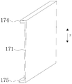
图7为本申请其他实施例防火构件的结构示意图;
图8为本申请实施例电池单体的爆炸图;
图9为本申请实施例电极组件为卷绕式结构的截面图;
图10为本申请实施例电极组件为叠片式结构的截面图。
本申请实施例
为了使本申请的目的、技术方案及优点更加清楚明白,以下结合附图及实施例,对本申请部分实施例进行进一步详细说明。应当理解,此处所描述的具体实施例仅仅用以解释本申请,并不用于限定本申请。
请参阅图1,本实施例涉及一种电池包,该电池包包括容纳箱以及设置在容纳箱内的多个电池模块1,多个电池模块1可以沿水平方向(箭头x所指的长度方向或者箭头y所指的宽度方向)排列,也可以沿竖直方向(箭头z所指方向)排列。
例如,容纳箱包括箱盖2以及箱体3,箱体3上设置有多个固定梁31。 另外,在其他实施例中,固定梁31可以设置在箱盖2上。本实施例中,固定梁31可以为箱体3的底部向上凸起的凸起梁或者单独作为零部件焊接在箱体3的底部。
电池包还包括压条4,压条4将电池模块1的两端压紧在固定梁31上,以将电池模块1固定在箱体3上。此时,通过压条4对电池模块1进行固定。
如图2所示,本实施例中,电池模块1包括上盖13、下盖14、防火构件17、灭火构件18以及两个电池单体排列结构10(也可以是大于两个的电池单体排列结构10),其中一个电池单体排列结构10为第一电池单体排列结构101,另一个与第一电池单体排列结构101邻近的电池单体排列结构10为第二电池单体排列结构102。第一电池单体排列结构101与第二电池单体排列结构102均设置在上盖13与下盖14之间。
本实施例中,第一电池单体排列结构101与第二电池单体排列结构102均包括沿长度方向(箭头x所指的长度方向)排列的十四个电池单体11。当然,可根据需要调整电池单体11的数量、长度、高度、体积等。
在其他实施例中,电池模块1还可以只设置一个电池单体排列结构10,在电池单体排列结构10中,每个电池单体11均设置有防爆阀116,并且电池单体排列结构10的防爆阀116均面向防火构件17。
防火构件17竖直设置,第一电池单体排列结构101的防爆阀116和第二电池单体排列结构102的防爆阀116均面向防火构件17,防火构件17位于第一电池单体排列结构101的防爆阀116和第二电池单体排列结构102的防爆阀116之间。
此时,防火构件17设置在第一电池单体排列结构101的防爆阀116与第二电池单体排列结构102的防爆阀116之间,防火构件17将第一电池单体排列结构101的电池单体11与第二电池单体排列结构102的电池单体11隔开,避免已发生热失控的电池单体11引发与其邻近的电池单体11也发生热失控。
例如,灭火构件18设置在电池单体排列结构10的下方,灭火构件18设有可存储灭火液的流体通道。灭火构件18沿电池单体11的排列方向延伸,并且在长度方向上(箭头x所指的长度方向)与电池单体排列结构10的长度大致相同,当然也可以不相同。
本实施例中,灭火构件18设置在下盖14的下方,灭火构件18内可以设置有灭火液,一方面,在电池模块1正常工作时,灭火液可以作为冷却液,用于对电池单体排列结构10的电池单体11进行冷却;另一方面,在电池单体11发生热失控起火时,灭火构件18熔化并释放出灭火液以扑灭火焰,从而减小电池单体11热失控的危害。
如图3所示,在电池单体11(可以是第一电池单体排列结构101的电池单体11或第二电池单体排列结构102的电池单体11)发生热失控时,防爆阀116破裂并且喷出火焰与高温颗粒5。此时,电池单体11沿水平方向(箭头x所指的长度方向或者箭头y所指的宽度方向)喷出火焰与高温颗粒5,火焰与高温颗粒5被防火构件17挡下,高温颗粒5向下,烧穿下盖14以及灭火构件18,引发灭火构件18内的灭火液对高温颗粒5进行降温,从而减小电池单体11热失控的危害。
如图4以及图5所示,本实施例中,电池单体排列结构10包括多个电池单体11以及电连接多个电池单体11的多个汇流排12,多个电池单体11沿水平方向(箭头x所指的长度方向或者箭头y所指的宽度方向)排列。采集板15位于电池单体排列结构10的一侧且竖直设置,采集板15与电池单体排列结构10中的电池单体11相连接。
本实施例中,电池单体排列结构10还包括两个端板16,两个端板16分别位于多个电池单体11沿水平方向(箭头x所指的长度方向或者箭头y所指的宽度方向)排列的两端。
在具体实施例中,电池单体11的侧面涂胶与相邻的电池单体11粘接,多个电池单体11的两端设置端板16,形成电池单体排列结构10。电池单体 11与电池单体11之间通过汇流排12实现电连接,在电池单体排列结构10的汇流排12位置设置采集板15。将电池单体排列结构10平躺在下盖14上,电池单体排列结构10的下表面通过结构胶与下盖14相固定,电池单体排列结构10的上表面通过结构胶与上盖13相固定。
如图6所示,本实施例中,防火构件17包括防火构件主体171以及连接于防火构件主体171上端的第一延伸部172,第一延伸部172朝靠近第一电池单体排列结构101的方向延伸。
防火构件17还包括第二延伸部173,第二延伸部173连接于防火构件主体171上端,第二延伸部173朝靠近第二电池单体排列结构102的方向延伸。本实施例中,第一延伸部172朝靠近第一电池单体排列结构101的方向延伸以及第二延伸部173朝靠近第二电池单体排列结构102的方向延伸,并不局限于图6中,第一延伸部172与第二延伸部173沿水平方向(箭头x所指的长度方向或者箭头y所指的宽度方向)的实施例,第一延伸部172与第二延伸部173也可以向上向下倾斜延伸,或者弧形延伸等。
另外,本实施例中,防火构件17的形状为T形,通过T形的防火构件17与灭火构件18的配合,既可以防止火焰与高温颗粒5沿竖直方向(箭头z所指方向)向上喷出而危急乘客舱,又可以让火焰与高温颗粒5向下喷出而熔化灭火构件18进一步减小电池单体11热失控的危害。
例如,防火构件主体171、第一延伸部172以及第二延伸部173为一体式结构。如此,便于防火构件17的加工。
如图7所示,在其他实施例中,防火构件17包括防火构件主体171以及连接于防火构件主体171上端的第三延伸部174,第三延伸部174朝靠近电池单体11的方向延伸;和/或,防火构件17包括防火构件主体171以及连接于防火构件主体171下端的第四延伸部175,第四延伸部175朝靠近电池单体11的方向延伸。
在其他实施例中,防火构件17包括防火构件主体171、第三延伸部174 以及第四延伸部175,并不限制第三延伸部174以及第四延伸部175的位置以及形状,第三延伸部174用于防止火焰与高温颗粒5沿竖直方向(箭头z所指方向)向上喷出,第四延伸部17用于防止火焰与高温颗粒5沿竖直方向(箭头z所指方向)向下喷出,同样其到保护作用。只要可以将火焰与高温颗粒5挡下,防止火焰与高温颗粒5烧毁相邻电池单体,均在本实施例的保护范围内。
然而,需要说明的是,并不排除上述防火构件17出现各种第一延伸部172、第二延伸部173、第三延伸部174、第四延伸部175任意组合的可能性,实际应用中,可以根据实际的情况,调整防火构件17的形状样式,以取得最佳效果,防火构件17并不局限于本实施例中的形状样式。
另外,防火构件17的熔点大于或等于500℃,使得火焰不会熔化防火构件17,以起到防火的作用。具体的,本实施例中防火构件17采用云母板的材质,由于云母板的熔点很高(大约1723℃),因此可以达到防火构件17的耐火需求,并且云母板具有优良的加工性能。但是,并不局限于云母板的实施例。
如图8所示,电池单体11包括电极组件111、电池壳体112、电极端子连接件113、盖板114以及电极端子115。电池壳体112可具有六面体形状或其他形状。电池壳体112具有容纳电极组件111和电解液的内部空间,并且电池壳体112具有开口。电极组件111容纳在电池壳体112内,盖板114覆盖开口,并用于将电极组件111封闭在电池壳体112内,电极组件111与电极端子115之间通过电极端子连接件113电连接。本实施例中,电极端子连接件113有两个,即分别为正极端子连接件113和负极端子连接件113。电池壳体112可以由例如铝、铝合金或塑料等材料制造。
电极组件111容纳于电池壳体112内,电极组件111包括第一极片1111、第二极片1112以及设置于第一极片1111和第二极片1112之间的隔膜1113。第一极片1111可以是正极片或负极片,第二极片1112与第一极片1111的极 性相反,相应地,第二极片1112为负极片或正极片。其中,隔膜1113是介于第一极片1111和第二极片1112之间的绝缘体。电极组件111可以是卷绕式结构(如图9),也可以是叠片式结构(如图10)。
示例性地以第一极片1111为正极片,第二极片1112为负极片进行说明。同样地,在其他的实施例中,第一极片1111还可以为负极片,而第二极片1112为正极片。另外,正极活性物质被涂覆在正极片的涂覆区上,而负极活性物质被涂覆到负极片的涂覆区上。从涂覆区延伸出的未涂覆区则作为极耳,电极组件111包括两个极耳,即正极耳和负极耳,正极耳从正极片的涂覆区延伸出;负极耳从负极片的涂覆区延伸出。正极耳与正电极端子115之间通过正极端子连接件113电连接,负极耳与负电极端子115之间通过负极端子连接件113电连接。
电池壳体112大致为六面体结构,电池壳体112包括两个第一表面1121和两个第二表面1122,第一表面1121的面积大于第二表面1122的面积。在电池模块1中,每个电池单体11的两个第二表面1122沿水平方向(例如箭头x所指方向的长度方向)相互面对,每个电池单体11的两个第一表面1121沿竖直方向(箭头z所指方向)相互面对。
如图9以及图10所示,当电极组件111为卷绕式结构时,电极组件111为扁平状,并且电极组件111的外表面包括两个扁平面1114,两个扁平面1114均沿竖直方向(箭头z所指方向)相互面对,即扁平面1114与第一表面1121相互面对。电极组件111大致为六面体结构,扁平面1114大致平行于卷绕轴线且为面积最大的外表面。扁平面1114可以是相对平整的表面,并不要求是纯平面。
如图10所示,当电极组件111为叠片式结构时,第一极片1111、隔膜1113和第二极片1112沿竖直方向(箭头z所指方向)层叠,即第一极片1111的表面与第一表面1121相互面对。
电极组件111在充放电过程中不可避免的会沿第一极片1111的厚度方 向发生膨胀(在卷绕式结构的电极组件111中,沿垂直于扁平面1114的方向膨胀力最大;在叠片式结构的电极组件111中,沿第一极片1111和第二极片1112的堆叠方向膨胀力最大)。
本实施例中,电极组件111可以选用卷绕式结构或者叠片式结构。当电极组件111为卷绕式结构时,扁平面1114朝向竖直方向(箭头z所指方向)。当电极组件111为叠片式结构时,第一极片1111和第二极片1112沿竖直方向(箭头z所指方向)层叠。可见,电极组件111无论是采用卷绕式结构还是采用叠片式结构,电极组件111对电池壳体112施加最大膨胀力的方向都朝向竖直方向。
而现有技术中,电池模块1的电池单体11中,电极组件111对电池壳体112施加最大膨胀力的方向都是朝向水平方向,由于电池模块1沿水平方向的尺寸相比于竖直方向的尺寸大的多(例如,受到车辆的底盘高度尺寸限制,需要有更多的电池单体11沿水平方向堆叠,膨胀力累积大),因此,现有电池模块1在水平方向上受到的膨胀力非常大,因此需要在电池模块1的水平方向两侧设置非常厚的端板以抵抗膨胀力,而端板加厚会降低电池模块1的能量密度。而本实施例中,电极组件111对电池壳体112施加最大膨胀力的方向是朝向竖直方向,而竖直方向上堆叠的电池单体11个数较少,因此相比于现有技术,可以大大减少电池模块1的最大膨胀力。
另外,由于电池单体11在充放电过程中还会在电池壳体112内部产生气体,产生的气体会对电池壳体112施加作用力,从而加剧电池壳体112向外膨胀。由于本申请的第一表面1121的面积大于第二表面1122的面积,并且电池单体11中的两个第一表面1121沿竖直方向相互面对,因此产生的气体对电池壳体112施加的最大作用力方向也是朝向竖直方向。相比于现有技术,进一步减少了电池模块1的最大膨胀力。
一个或多个实施例通过与之对应的附图中的图片进行示例性说明,这些示例性说明并不构成对实施例的限定,附图中具有相同参考数字标号的元 件表示为类似的元件,除非有特别申明,附图中的图不构成比例限制。
Claims (10)
- 一种电池模块,其中,包括:电池单体排列结构(10),所述电池单体排列结构(10)包括多个电池单体(11)以及电连接所述多个电池单体(11)的多个汇流排(12);上盖(13);下盖(14),所述电池单体排列结构(10)设置在所述上盖(13)与所述下盖(14)之间;以及防火构件(17),所述防火构件(17)竖直设置;其中,所述电池单体排列结构(10)的每个所述电池单体(11)均设置有防爆阀(116),所述电池单体排列结构(10)的所述防爆阀(116)均面向所述防火构件(17)。
- 根据权利要求1所述的电池模块,其中:所述电池模块(1)包括两个以上的所述电池单体排列结构(10),其中一个所述电池单体排列结构(10)为第一电池单体排列结构(101),另一个与所述第一电池单体排列结构(101)邻近的所述电池单体排列结构(10)为第二电池单体排列结构(102);所述第一电池单体排列结构(101)的所述防爆阀(116)和所述第二电池单体排列结构(102)的所述防爆阀(116)均面向所述防火构件(17),所述防火构件(17)位于所述第一电池单体排列结构(101)的所述防爆阀(116)和所述第二电池单体排列结构(102)的所述防爆阀(116)之间。
- 根据权利要求2所述的电池模块,其中:所述防火构件(17)包括防火构件主体(171)以及连接于所述防火构件主体(171)上端的第一延伸部(172),所述第一延伸部(172)朝靠近所述第一电池单体排列结构(101)的方向延伸。
- 根据权利要求3所述的电池模块,其中:所述防火构件(17)还包括第二延伸部(173),所述第二延伸部(173)连接于所述防火构件主体(171)上端,所述第二延伸部(173)朝靠近所述第二电池单体排列结构(102)的方向延伸。
- 根据权利要求3或4所述的电池模块,其中:所述电池模块(1)还包括灭火构件(18),所述灭火构件(18)设置在所述电池单体排列结构(10)的下方,所述灭火构件(18)设有可存储灭火液的流体通道。
- 根据权利要求4所述的电池模块,其中:所述防火构件主体(171)、所述第一延伸部(172)以及所述第二延伸部(173)为一体式结构。
- 根据权利要求1-6任意一项所述的电池模块,其中:所述防火构件(17)包括防火构件主体(171)以及连接于所述防火构件主体(171)上端的第三延伸部(174),所述第三延伸部(174)朝靠近所述电池单体(11)的方向延伸;和/或,所述防火构件(17)包括防火构件主体(171)以及连接于所述防火构件主体(171)下端的第四延伸部(175),所述第四延伸部(175)朝靠近所述电池单体(11)的方向延伸。
- 根据权利要求1-7任意一项所述的电池模块,其中:所述电池单体排列结构(10)还包括采集板(15),所述采集板(15)位于所述电池单体排列结构(10)的一侧,所述采集板(15)与所述电池单体排列结构(10)中的所述电池单体(11)相连接。
- 根据权利要求1-8任意一项所述的电池模块,其中:所述防火构件(17)的熔点大于或等于500℃。
- 一种电池包,其中,包括:容纳箱,以及设置在所述容纳箱内的多个如权利要求1-9任意一项所述的电池模块(1)。
Priority Applications (1)
| Application Number | Priority Date | Filing Date | Title |
|---|---|---|---|
| JP2021550113A JP7368486B2 (ja) | 2019-03-07 | 2020-02-24 | 電池モジュール及び電池パック |
Applications Claiming Priority (2)
| Application Number | Priority Date | Filing Date | Title |
|---|---|---|---|
| CN201910173449.0A CN111668404B (zh) | 2019-03-07 | 2019-03-07 | 一种电池模块及电池包 |
| CN201910173449.0 | 2019-03-07 |
Publications (1)
| Publication Number | Publication Date |
|---|---|
| WO2020177569A1 true WO2020177569A1 (zh) | 2020-09-10 |
Family
ID=67070649
Family Applications (1)
| Application Number | Title | Priority Date | Filing Date |
|---|---|---|---|
| PCT/CN2020/076479 Ceased WO2020177569A1 (zh) | 2019-03-07 | 2020-02-24 | 一种电池模块及电池包 |
Country Status (6)
| Country | Link |
|---|---|
| US (1) | US11705604B2 (zh) |
| EP (1) | EP3706190B1 (zh) |
| JP (1) | JP7368486B2 (zh) |
| CN (1) | CN111668404B (zh) |
| PL (1) | PL3706190T3 (zh) |
| WO (1) | WO2020177569A1 (zh) |
Cited By (1)
| Publication number | Priority date | Publication date | Assignee | Title |
|---|---|---|---|---|
| JP2024526064A (ja) * | 2022-02-18 | 2024-07-17 | エルジー エナジー ソリューション リミテッド | 内部空間の仕切りのための仕切膜を適用したバッテリーモジュール及びこれを含むバッテリーパック |
Families Citing this family (31)
| Publication number | Priority date | Publication date | Assignee | Title |
|---|---|---|---|---|
| US12090354B2 (en) | 2019-09-05 | 2024-09-17 | Samsung Sdi Co., Ltd. | Energy storage module |
| US11848461B2 (en) | 2019-09-05 | 2023-12-19 | Samsung Sdi Co., Ltd. | Energy storage module |
| US11799167B2 (en) | 2019-09-05 | 2023-10-24 | Samsung Sdi Co., Ltd. | Energy storage module having extinguisher sheet |
| US12355098B2 (en) | 2019-09-05 | 2025-07-08 | Samsung Sdi Co., Ltd. | Energy storage module |
| US11728541B2 (en) | 2019-09-05 | 2023-08-15 | Samsung Sdi Co., Ltd. | Energy storage module |
| US12057598B2 (en) | 2019-09-05 | 2024-08-06 | Samsung Sdi Co., Ltd. | Energy storage module including extinguisher sheet |
| US11764430B2 (en) | 2019-09-05 | 2023-09-19 | Samsung Sdi Co., Ltd. | Energy storage module |
| US12300848B2 (en) | 2019-09-05 | 2025-05-13 | Samsung Sdi Co., Ltd. | Energy storage module including extinguisher sheet |
| US11771935B2 (en) | 2019-09-05 | 2023-10-03 | Samsung Sdi Co., Ltd. | Energy storage module |
| US12288895B2 (en) * | 2019-09-05 | 2025-04-29 | Samsung Sdi Co., Ltd. | Energy storage module |
| US11764438B2 (en) | 2019-09-05 | 2023-09-19 | Samsung Sdi Co., Ltd. | Energy storage module having extinguisher sheet |
| US11735788B2 (en) | 2019-09-05 | 2023-08-22 | Samsung Sdi Co., Ltd. | Energy storage module including insulation spacers and an extinguisher sheet |
| US11735795B2 (en) | 2019-09-05 | 2023-08-22 | Samsung Sdi Co., Ltd. | Energy storage module |
| US11569546B2 (en) | 2019-09-05 | 2023-01-31 | Samsung Sdi Co., Ltd. | Energy storage module |
| CN112072046B (zh) * | 2020-10-19 | 2022-12-27 | 江苏时代新能源科技有限公司 | 电池、用电装置、制备电池的方法和设备 |
| EP4071911B1 (en) | 2020-10-19 | 2024-07-17 | Jiangsu Contemporary Amperex Technology Limited | Battery, power consuming device and method for producing battery |
| JP7644219B2 (ja) | 2020-12-07 | 2025-03-11 | エルジー エナジー ソリューション リミテッド | 電池モジュールおよびそれを含む電池パック |
| CN214428739U (zh) * | 2020-12-31 | 2021-10-19 | 江苏塔菲尔动力系统有限公司 | 一种防热失控的组件及电池模组 |
| KR102957880B1 (ko) * | 2021-01-08 | 2026-04-24 | 주식회사 엘지에너지솔루션 | 배터리 팩 및 이를 포함하는 자동차 |
| KR102825807B1 (ko) * | 2021-01-15 | 2025-06-25 | 주식회사 엘지에너지솔루션 | 화재 발생 및 폭발을 방지할 수 있는 구조를 갖는 배터리 모듈, 그리고 이를 포함하는 배터리 팩 및 ess |
| CN112652857B (zh) * | 2021-01-19 | 2022-10-28 | 中国第一汽车股份有限公司 | 一种动力电池、动力电池的热扩散防护方法及车辆 |
| KR102945306B1 (ko) * | 2021-02-22 | 2026-03-30 | 에스케이온 주식회사 | 배터리 셀 어셈블리 및 이를 포함하는 배터리 팩 |
| CN115458857B (zh) * | 2021-06-09 | 2024-08-13 | 太普动力新能源(常熟)股份有限公司 | 电池模块 |
| KR20230046685A (ko) * | 2021-09-30 | 2023-04-06 | 에스케이온 주식회사 | 배터리 팩 |
| WO2023137578A1 (zh) * | 2022-01-18 | 2023-07-27 | 宁德时代新能源科技股份有限公司 | 一种电池采样装置、电池及用电装置 |
| CN116526074A (zh) * | 2022-01-24 | 2023-08-01 | 宁德时代新能源科技股份有限公司 | 电池和用电装置 |
| EP4261966A1 (en) * | 2022-04-12 | 2023-10-18 | Volocopter GmbH | Battery cell module and arrangement |
| JP2024014075A (ja) * | 2022-07-21 | 2024-02-01 | プライムプラネットエナジー&ソリューションズ株式会社 | 蓄電モジュール |
| CN223927561U (zh) * | 2022-09-30 | 2026-02-17 | 宁德时代新能源科技股份有限公司 | 电池及用电装置 |
| CN220553548U (zh) * | 2023-05-18 | 2024-03-01 | 晶科储能科技有限公司 | 电池模组与电池包 |
| CN119812616B (zh) * | 2024-12-23 | 2025-09-26 | 无锡中晟精密科技有限公司 | 一种新能源电池装载盒模具 |
Citations (6)
| Publication number | Priority date | Publication date | Assignee | Title |
|---|---|---|---|---|
| US20150171388A1 (en) * | 2013-12-16 | 2015-06-18 | Samsung Sdi Co., Ltd. | Battery module |
| CN205542960U (zh) * | 2016-01-29 | 2016-08-31 | 广东精进能源有限公司 | 一种散热防火电源模块 |
| CN107093686A (zh) * | 2017-04-28 | 2017-08-25 | 北京新能源汽车股份有限公司 | 电池包和车辆 |
| CN207409556U (zh) * | 2017-10-31 | 2018-05-25 | 宁德时代新能源科技股份有限公司 | 电池模组 |
| CN208315702U (zh) * | 2018-06-07 | 2019-01-01 | 江苏南极星新能源技术股份有限公司 | 大功率模块化集成储能设备 |
| CN209447890U (zh) * | 2019-03-07 | 2019-09-27 | 宁德时代新能源科技股份有限公司 | 一种电池模块及电池包 |
Family Cites Families (28)
| Publication number | Priority date | Publication date | Assignee | Title |
|---|---|---|---|---|
| JPH04162347A (ja) * | 1990-10-26 | 1992-06-05 | Nippon Telegr & Teleph Corp <Ntt> | 電池パック |
| JP2008218210A (ja) * | 2007-03-05 | 2008-09-18 | Lenovo Singapore Pte Ltd | 電池パックおよび携帯式電子機器 |
| US8399116B2 (en) * | 2007-12-25 | 2013-03-19 | Byd Co. Ltd. | Optimized dimensional relationships for an electrochemical cell having a coiled core |
| US9337457B2 (en) * | 2010-06-24 | 2016-05-10 | Samsung Sdi Co., Ltd. | Battery assembly with cooling |
| JP4965750B2 (ja) | 2010-07-30 | 2012-07-04 | パナソニック株式会社 | 電池システム |
| JP2012119138A (ja) | 2010-11-30 | 2012-06-21 | Panasonic Corp | 電池モジュール |
| US20120308873A1 (en) * | 2011-06-02 | 2012-12-06 | Masahiro Sekino | Secondary battery apparatus and method of manufacturing secondary battery apparatus |
| JP5461610B2 (ja) * | 2012-03-22 | 2014-04-02 | 三菱重工業株式会社 | 電池及び電池システム |
| JP6103887B2 (ja) | 2012-11-01 | 2017-03-29 | ホーチキ株式会社 | 電力貯蔵システム |
| US9440601B2 (en) * | 2013-09-06 | 2016-09-13 | Johnson Controls Technology Company | System for providing voltage measurements of battery cells to a PCB within a battery module |
| JP6284085B2 (ja) * | 2013-09-30 | 2018-02-28 | パナソニックIpマネジメント株式会社 | 電池固定用フレーム部材、電池固定部材及び蓄電装置 |
| KR20150066077A (ko) * | 2013-12-06 | 2015-06-16 | 삼성에스디아이 주식회사 | 배터리 모듈 |
| JP6287637B2 (ja) | 2014-06-30 | 2018-03-07 | 株式会社豊田自動織機 | 電池モジュール |
| JP6299513B2 (ja) | 2014-07-31 | 2018-03-28 | 株式会社Gsユアサ | 電源パック |
| JP6476915B2 (ja) * | 2015-01-27 | 2019-03-06 | 株式会社デンソー | 電池パック |
| JP6574309B2 (ja) * | 2015-12-09 | 2019-09-11 | エルジー・ケム・リミテッド | バッテリーパック及びこれを含む自動車 |
| EP3410512B1 (en) | 2016-01-26 | 2022-02-16 | Sanyo Electric Co., Ltd. | Battery pack |
| TWM556938U (zh) * | 2017-01-09 | 2018-03-11 | 財團法人工業技術研究院 | 具散熱及熱失控擴散防護之電池模組 |
| CN106785225A (zh) * | 2017-03-14 | 2017-05-31 | 合肥国轩高科动力能源有限公司 | 被动防护电池模组结构及其制作方法 |
| CN109428027A (zh) * | 2017-09-03 | 2019-03-05 | 湖州南浔遨优电池有限公司 | 一种隔热防火防爆电池组 |
| JP7174707B2 (ja) | 2017-09-29 | 2022-11-17 | 三洋電機株式会社 | 電源装置 |
| CN108110171B (zh) * | 2017-11-29 | 2020-11-06 | 南京航空航天大学 | 圆柱形动力电池模组 |
| CN108011064A (zh) * | 2017-12-29 | 2018-05-08 | 安徽零度新能源科技有限公司 | 一种动力锂电池防火壳体 |
| CN108615835B (zh) * | 2018-05-04 | 2021-01-22 | 安徽上造智能设备科技有限公司 | 一种新能源汽车用高强度防爆自主散热电池 |
| CN108615838B (zh) * | 2018-05-04 | 2021-01-22 | 安徽上造智能设备科技有限公司 | 一种新能源汽车用高强度防爆防震电池 |
| CN209249549U (zh) * | 2018-12-30 | 2019-08-13 | 宁德时代新能源科技股份有限公司 | 一种电池包 |
| CN209249548U (zh) * | 2018-12-30 | 2019-08-13 | 宁德时代新能源科技股份有限公司 | 一种电池模块及电池包 |
| CN111668527B (zh) * | 2019-03-07 | 2024-10-22 | 宁德时代新能源科技股份有限公司 | 一种电池模块及电池包 |
-
2019
- 2019-03-07 CN CN201910173449.0A patent/CN111668404B/zh active Active
- 2019-06-25 EP EP19182332.7A patent/EP3706190B1/en active Active
- 2019-06-25 PL PL19182332T patent/PL3706190T3/pl unknown
- 2019-07-10 US US16/507,318 patent/US11705604B2/en active Active
-
2020
- 2020-02-24 WO PCT/CN2020/076479 patent/WO2020177569A1/zh not_active Ceased
- 2020-02-24 JP JP2021550113A patent/JP7368486B2/ja active Active
Patent Citations (6)
| Publication number | Priority date | Publication date | Assignee | Title |
|---|---|---|---|---|
| US20150171388A1 (en) * | 2013-12-16 | 2015-06-18 | Samsung Sdi Co., Ltd. | Battery module |
| CN205542960U (zh) * | 2016-01-29 | 2016-08-31 | 广东精进能源有限公司 | 一种散热防火电源模块 |
| CN107093686A (zh) * | 2017-04-28 | 2017-08-25 | 北京新能源汽车股份有限公司 | 电池包和车辆 |
| CN207409556U (zh) * | 2017-10-31 | 2018-05-25 | 宁德时代新能源科技股份有限公司 | 电池模组 |
| CN208315702U (zh) * | 2018-06-07 | 2019-01-01 | 江苏南极星新能源技术股份有限公司 | 大功率模块化集成储能设备 |
| CN209447890U (zh) * | 2019-03-07 | 2019-09-27 | 宁德时代新能源科技股份有限公司 | 一种电池模块及电池包 |
Cited By (2)
| Publication number | Priority date | Publication date | Assignee | Title |
|---|---|---|---|---|
| JP2024526064A (ja) * | 2022-02-18 | 2024-07-17 | エルジー エナジー ソリューション リミテッド | 内部空間の仕切りのための仕切膜を適用したバッテリーモジュール及びこれを含むバッテリーパック |
| JP7719889B2 (ja) | 2022-02-18 | 2025-08-06 | エルジー エナジー ソリューション リミテッド | 内部空間の仕切りのための仕切膜を適用したバッテリーモジュール及びこれを含むバッテリーパック |
Also Published As
| Publication number | Publication date |
|---|---|
| CN111668404A (zh) | 2020-09-15 |
| JP2022523777A (ja) | 2022-04-26 |
| US11705604B2 (en) | 2023-07-18 |
| US20200287180A1 (en) | 2020-09-10 |
| EP3706190A1 (en) | 2020-09-09 |
| CN111668404B (zh) | 2024-12-03 |
| EP3706190B1 (en) | 2021-04-07 |
| PL3706190T3 (pl) | 2021-08-30 |
| JP7368486B2 (ja) | 2023-10-24 |
Similar Documents
| Publication | Publication Date | Title |
|---|---|---|
| JP7368486B2 (ja) | 電池モジュール及び電池パック | |
| CN209249548U (zh) | 一种电池模块及电池包 | |
| US11955655B2 (en) | Protective plate, battery unit assembly, battery module group and vehicle | |
| CN210092179U (zh) | 电池模组、电池包和车辆 | |
| CN111384343B (zh) | 一种电池包 | |
| US11133554B2 (en) | Battery pack and vehicle | |
| JP2022510652A (ja) | ガス排出路を備えたベースプレートを含むバッテリーモジュール及びバッテリーパック並びに電力貯蔵装置 | |
| CN216720195U (zh) | 电池模块、电池及用电装置 | |
| WO2020177721A1 (zh) | 一种电池模块及电池包 | |
| WO2023010516A1 (zh) | 电池的箱体、电池、用电装置、制备电池的方法和装置 | |
| CN209496936U (zh) | 电池模组 | |
| WO2022082389A1 (zh) | 电池、用电设备、制备电池的方法和装置 | |
| US12519179B2 (en) | Battery pack and device including the same | |
| CN209447890U (zh) | 一种电池模块及电池包 | |
| CN115832548B (zh) | 电池单体、电池以及用电装置 | |
| KR20230039836A (ko) | 내부 화재시 열 전이 차단 구조를 구비한 배터리 모듈 | |
| KR20240012290A (ko) | 배터리 모듈 및, 이를 포함하는 배터리 팩 및 이를 포함하는 자동차 | |
| CN218731612U (zh) | 电池装置 | |
| EP4407774A1 (en) | Battery cell unit, and battery pack and vehicle including same | |
| WO2022170485A1 (zh) | 电池、用电装置、制备电池的方法和制备电池的装置 | |
| KR102876311B1 (ko) | 전지 팩 및 이를 포함하는 디바이스 | |
| CN209249549U (zh) | 一种电池包 | |
| WO2023060656A1 (zh) | 电池、用电装置、制备电池的方法和装置 | |
| CN209709060U (zh) | 电池模块和电池包 | |
| JP7722718B2 (ja) | 電池モジュールおよびそれを含む電池パック |
Legal Events
| Date | Code | Title | Description |
|---|---|---|---|
| 121 | Ep: the epo has been informed by wipo that ep was designated in this application |
Ref document number: 20765959 Country of ref document: EP Kind code of ref document: A1 |
|
| ENP | Entry into the national phase |
Ref document number: 2021550113 Country of ref document: JP Kind code of ref document: A |
|
| NENP | Non-entry into the national phase |
Ref country code: DE |
|
| 122 | Ep: pct application non-entry in european phase |
Ref document number: 20765959 Country of ref document: EP Kind code of ref document: A1 |