WO2020174716A1 - 構造体 - Google Patents
構造体 Download PDFInfo
- Publication number
- WO2020174716A1 WO2020174716A1 PCT/JP2019/029759 JP2019029759W WO2020174716A1 WO 2020174716 A1 WO2020174716 A1 WO 2020174716A1 JP 2019029759 W JP2019029759 W JP 2019029759W WO 2020174716 A1 WO2020174716 A1 WO 2020174716A1
- Authority
- WO
- WIPO (PCT)
- Prior art keywords
- bed
- switch
- side rail
- angle
- bed apparatus
- Prior art date
- Legal status (The legal status is an assumption and is not a legal conclusion. Google has not performed a legal analysis and makes no representation as to the accuracy of the status listed.)
- Ceased
Links
Images


Classifications
-
- A—HUMAN NECESSITIES
- A47—FURNITURE; DOMESTIC ARTICLES OR APPLIANCES; COFFEE MILLS; SPICE MILLS; SUCTION CLEANERS IN GENERAL
- A47C—CHAIRS; SOFAS; BEDS
- A47C21/00—Attachments for beds, e.g. sheet holders or bed-cover holders; Ventilating, cooling or heating means in connection with bedsteads or mattresses
- A47C21/08—Devices for prevention against falling-out, e.g. detachable side walls
-
- A—HUMAN NECESSITIES
- A61—MEDICAL OR VETERINARY SCIENCE; HYGIENE
- A61G—TRANSPORT, PERSONAL CONVEYANCES, OR ACCOMMODATION SPECIALLY ADAPTED FOR PATIENTS OR DISABLED PERSONS; OPERATING TABLES OR CHAIRS; CHAIRS FOR DENTISTRY; FUNERAL DEVICES
- A61G7/00—Beds specially adapted for nursing; Devices for lifting patients or disabled persons
- A61G7/05—Parts, details or accessories of beds
- A61G7/053—Aids for getting into, or out of, bed, e.g. steps, chairs, cane-like supports
-
- A—HUMAN NECESSITIES
- A61—MEDICAL OR VETERINARY SCIENCE; HYGIENE
- A61G—TRANSPORT, PERSONAL CONVEYANCES, OR ACCOMMODATION SPECIALLY ADAPTED FOR PATIENTS OR DISABLED PERSONS; OPERATING TABLES OR CHAIRS; CHAIRS FOR DENTISTRY; FUNERAL DEVICES
- A61G7/00—Beds specially adapted for nursing; Devices for lifting patients or disabled persons
- A61G7/002—Beds specially adapted for nursing; Devices for lifting patients or disabled persons having adjustable mattress frame
- A61G7/005—Beds specially adapted for nursing; Devices for lifting patients or disabled persons having adjustable mattress frame tiltable around transverse horizontal axis, e.g. for Trendelenburg position
-
- A—HUMAN NECESSITIES
- A61—MEDICAL OR VETERINARY SCIENCE; HYGIENE
- A61G—TRANSPORT, PERSONAL CONVEYANCES, OR ACCOMMODATION SPECIALLY ADAPTED FOR PATIENTS OR DISABLED PERSONS; OPERATING TABLES OR CHAIRS; CHAIRS FOR DENTISTRY; FUNERAL DEVICES
- A61G7/00—Beds specially adapted for nursing; Devices for lifting patients or disabled persons
- A61G7/002—Beds specially adapted for nursing; Devices for lifting patients or disabled persons having adjustable mattress frame
- A61G7/015—Beds specially adapted for nursing; Devices for lifting patients or disabled persons having adjustable mattress frame divided into different adjustable sections, e.g. for Gatch position
-
- A—HUMAN NECESSITIES
- A61—MEDICAL OR VETERINARY SCIENCE; HYGIENE
- A61G—TRANSPORT, PERSONAL CONVEYANCES, OR ACCOMMODATION SPECIALLY ADAPTED FOR PATIENTS OR DISABLED PERSONS; OPERATING TABLES OR CHAIRS; CHAIRS FOR DENTISTRY; FUNERAL DEVICES
- A61G7/00—Beds specially adapted for nursing; Devices for lifting patients or disabled persons
- A61G7/002—Beds specially adapted for nursing; Devices for lifting patients or disabled persons having adjustable mattress frame
- A61G7/018—Control or drive mechanisms
-
- A—HUMAN NECESSITIES
- A61—MEDICAL OR VETERINARY SCIENCE; HYGIENE
- A61G—TRANSPORT, PERSONAL CONVEYANCES, OR ACCOMMODATION SPECIALLY ADAPTED FOR PATIENTS OR DISABLED PERSONS; OPERATING TABLES OR CHAIRS; CHAIRS FOR DENTISTRY; FUNERAL DEVICES
- A61G7/00—Beds specially adapted for nursing; Devices for lifting patients or disabled persons
- A61G7/05—Parts, details or accessories of beds
- A61G7/0507—Side-rails
- A61G7/0508—Side-rails characterised by a particular connection mechanism
- A61G7/0509—Side-rails characterised by a particular connection mechanism sliding or pivoting downwards
-
- A—HUMAN NECESSITIES
- A61—MEDICAL OR VETERINARY SCIENCE; HYGIENE
- A61G—TRANSPORT, PERSONAL CONVEYANCES, OR ACCOMMODATION SPECIALLY ADAPTED FOR PATIENTS OR DISABLED PERSONS; OPERATING TABLES OR CHAIRS; CHAIRS FOR DENTISTRY; FUNERAL DEVICES
- A61G7/00—Beds specially adapted for nursing; Devices for lifting patients or disabled persons
- A61G7/05—Parts, details or accessories of beds
- A61G7/0527—Weighing devices
-
- A—HUMAN NECESSITIES
- A61—MEDICAL OR VETERINARY SCIENCE; HYGIENE
- A61G—TRANSPORT, PERSONAL CONVEYANCES, OR ACCOMMODATION SPECIALLY ADAPTED FOR PATIENTS OR DISABLED PERSONS; OPERATING TABLES OR CHAIRS; CHAIRS FOR DENTISTRY; FUNERAL DEVICES
- A61G2203/00—General characteristics of devices
- A61G2203/30—General characteristics of devices characterised by sensor means
- A61G2203/44—General characteristics of devices characterised by sensor means for weight
-
- A—HUMAN NECESSITIES
- A61—MEDICAL OR VETERINARY SCIENCE; HYGIENE
- A61G—TRANSPORT, PERSONAL CONVEYANCES, OR ACCOMMODATION SPECIALLY ADAPTED FOR PATIENTS OR DISABLED PERSONS; OPERATING TABLES OR CHAIRS; CHAIRS FOR DENTISTRY; FUNERAL DEVICES
- A61G7/00—Beds specially adapted for nursing; Devices for lifting patients or disabled persons
- A61G7/002—Beds specially adapted for nursing; Devices for lifting patients or disabled persons having adjustable mattress frame
- A61G7/012—Beds specially adapted for nursing; Devices for lifting patients or disabled persons having adjustable mattress frame raising or lowering of the whole mattress frame
-
- A—HUMAN NECESSITIES
- A61—MEDICAL OR VETERINARY SCIENCE; HYGIENE
- A61G—TRANSPORT, PERSONAL CONVEYANCES, OR ACCOMMODATION SPECIALLY ADAPTED FOR PATIENTS OR DISABLED PERSONS; OPERATING TABLES OR CHAIRS; CHAIRS FOR DENTISTRY; FUNERAL DEVICES
- A61G7/00—Beds specially adapted for nursing; Devices for lifting patients or disabled persons
- A61G7/05—Parts, details or accessories of beds
- A61G7/0507—Side-rails
- A61G7/052—Side-rails characterised by safety means, e.g. to avoid injuries to patient or caregiver
Definitions
- Embodiments of the present invention relate to structures.
- Embodiments of the present invention provide a structure that can assist in getting out of bed.
- the structure is removably attached to the bed apparatus.
- the bed apparatus includes a holding unit and a first frame including a portion extending in the first direction.
- the structure has a columnar first portion that extends in a second direction that intersects the first direction, and a second portion that includes a portion that is connected to the first portion and that extends in a third direction that intersects the second direction. including.
- the first portion is inserted into the holding portion, and the holding portion holds the structure.
- FIG. 1A to 1C are schematic perspective views illustrating a bed apparatus according to an embodiment.
- FIG. 2 is a schematic perspective view illustrating the bed apparatus according to the embodiment.
- 3A and 3B are schematic perspective views illustrating the bed apparatus according to the embodiment.
- FIG. 4 is a schematic perspective view illustrating a part of the bed apparatus according to the embodiment.
- FIG. 5 is a schematic perspective view illustrating a part of the bed apparatus according to the embodiment.
- FIG. 6 is a schematic perspective view illustrating a part of the bed apparatus according to the embodiment.
- FIG. 7 is a schematic perspective view illustrating one operating state of the bed apparatus according to the embodiment.
- FIG. 8 is a schematic perspective view illustrating the bed apparatus according to the embodiment.
- FIG. 9 is a schematic perspective view illustrating the bed apparatus according to the embodiment.
- 10A to 10C are schematic views illustrating a part of the bed apparatus according to the embodiment.
- 11A and 11B are schematic views illustrating a part of the bed apparatus according to the embodiment.
- 12A to 12C are schematic views illustrating a part of the bed apparatus according to the embodiment.
- 13A and 13B are schematic views illustrating a part of the bed apparatus according to the embodiment.
- FIG. 14 is a schematic view illustrating a part of the bed apparatus according to the embodiment.
- FIG. 15: is a schematic diagram which illustrates a part of bed apparatus which concerns on embodiment.
- 16A and 16B are schematic views illustrating a part of the bed apparatus according to the embodiment.
- 17(a) to 17(c) are schematic perspective views illustrating the operation of the bed apparatus according to the embodiment.
- FIG. 18A and 18B are schematic perspective views illustrating the usage state of the bed apparatus according to the embodiment.
- FIG. 19 is a schematic view illustrating the bed apparatus according to the embodiment.
- 20A and 20B are schematic views illustrating a part of the bed apparatus according to the embodiment.
- 21A and 21B are schematic views illustrating a part of the bed apparatus according to the embodiment.
- FIG. 22 is a schematic view illustrating a part of the bed apparatus according to the embodiment.
- FIG. 23 is a schematic perspective view illustrating a part of the bed apparatus according to the embodiment.
- FIG. 24 is a schematic view illustrating a part of the bed apparatus according to the embodiment.
- 25A and 25B are schematic views illustrating a part of the bed apparatus according to the embodiment.
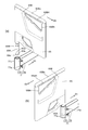
- FIG. 1A the bed apparatus 110 includes a first frame 71 and a structure body 65.
- the bed apparatus 110 may include a base frame 75B, a headboard 78A, a footboard 78B, a mattress 78M, and the like.
- a back bottom 70a, a knee bottom 70b, a foot bottom 70c, and the like may be provided.
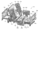
- FIG. 1(c) illustrates a state in which the headboard 78A, the footboard 78B, the mattress 78M, the bottom and the like are removed.
- the first frame 71 and the like are fixed to the base frame 75B.
- a foot bottom 70c (see FIG. 1A) is provided on the first frame 71, for example.
- a mattress 78M is provided on the back bottom 70a, the knee bottom 70b, and the foot bottom 70c.
- a user of the bed apparatus 110 can lie on the mattress 78M.
- Mattress 78M is located between headboard 78A and footboard 78B.
- the direction from the headboard 78A to the footboard 78B corresponds to the “longitudinal direction” of the bed apparatus 110.
- the bed apparatus 110 has a length direction Dh and a width direction Dw.
- the length of the bed apparatus 110 in the length direction Dh is longer than the length of the bed apparatus 110 in the width direction Dw.
- the base frame 75B extends along the length direction Dh.
- the first frame 71 includes a holding portion 71h.
- the first frame 71 includes a portion extending in the first direction D1.
- the portion extending in the first direction D1 is the extending portion 71e.
- the first direction D1 is along the width direction Dw.
- the first direction D1 may be along the length direction Dh.
- the first direction D1 may be inclined with respect to the width direction Dw or the length direction Dh and is arbitrary.
- the first frame 71 includes a frame body 71r.
- the frame body 71r includes a portion along the width direction Dw and a portion along the length direction Dh. One of these portions of the frame body 71r may correspond to the “portion extending in the first direction D1”.
- the holding portion 71h is fixed to the extending portion 71e.
- the holding portion 71h is provided at the end of the extending portion 71e.
- the structure 65 includes a first portion 65A and a second portion 65B. As shown in FIG. 2, the first portion 65A extends in the second direction D2. The second direction D2 intersects the first direction D1. The first portion 65A has a columnar shape extending in the second direction D2. The second direction D2 is, for example, a vertical direction (height direction).
- the second part 65B is connected to the first part 65A.
- the second portion 65B includes a portion extending in the third direction D3.
- the third direction D3 intersects the second direction D2.
- the first portion 65A is inserted into the holding portion 71h, and the holding portion 71h holds the structure 65.
- the angle between the first direction D1 and the third direction D3 is variable.
- the position (angle) of the second portion 65B can be changed with the first portion 65A as the axis of rotation.
- the structure 65 (or the second portion 65B) can have a plurality of states (a first state, a second state, etc.).
- the bed apparatus 110 can have a plurality of states (a first state, a second state, etc.).
- the bed apparatus 110 (structure 65) is in the first state ST1.
- the bed apparatus 110 (structure 65) is in the second state ST2.
- the angle between the first direction D1 and the third direction D3 in the first state ST1 (FIG. 1A) is the first angle.
- the first angle is substantially 90 degrees.
- the angle between the first direction D1 and the third direction D3 in the second state ST2 (FIG. 1B) is the second angle.
- the second angle is substantially 0 degrees or substantially 180 degrees.
- the first angle in the first state ST1 is different from the second angle in the second state ST2.
- the structure body 65 functions as a part of the side rail.
- the structure body 65 functions as a side rail spacer. This can prevent the user from falling off the bed device 110.
- the user can use the second portion 65B of the structure 65 as a “grip”.
- the user can easily get out of bed by adding the weight to the second portion 65B.
- the structure 65 is attached to the holding portion 71h of the first frame 71.
- the first frame 71 is fixed to the base frame 75B and is stable. This also stabilizes the structure 65. Thereby, for example, the user can comfortably add weight to the second portion 65B of the structure 65. Since you can feel relieved, you can promote leaving the bed more.
- the difference between the first angle and the second angle is substantially 90 degrees (for example, 80 degrees or more and 100 degrees or less).
- the third direction D3 is along the length direction Dh.
- the third direction D3 is along the width direction Dw.
- the holding portion 71h is preferably below the foot bottom 70c. Since the holding portion 71h is located below, for example, the user on the bed cannot easily remove the structure 65, and the user can be prevented from falling from the bed apparatus 110. Since the holding portion 71h is below the foot bottom 70c, the structure 65 can be held more stably.
- the position of the holding portion 71h in the width direction Dw is preferably outside the foot bottom 70c in the width direction Dw. This can prevent the holding portion 71h or the structure 65 from restricting the movement of the foot bottom 70c.
- the first frame 71 may be provided with a plurality of holding portions 71h.
- the plurality of holding units 71h are provided on the left and right of the bed apparatus 110, for example.
- the structure 65 may be provided in each of the left and right holding portions 71h.
- the structure 65 may be provided on the left and right holding portions 71h.
- the bed apparatus 110 may further include a second frame 72 and a first side rail 61.
- the first side rail 61 is held by the second frame 72.
- the first frame 71 on which the structure 65 is provided is fixed to the base frame 75B.
- the angle between the first frame 71 and the base frame 75B is constant.
- the second frame 72 has a variable angle with respect to the base frame 75B.
- the second frame 72 is held by the base frame 75B so that the angle between the second frame 72 and the base frame 75B can be changed.
- the second frame 72 may be substantially the back bottom 70a.
- the “second frame 72” is a member whose angle can be changed, and is, for example, a member capable of “raising the back”. The angle is changed by, for example, an actuator.
- the first side rail 61 moves together with the movement of the second frame 72 (raising the back). It is possible to further prevent the user from falling off the bed apparatus 110 in the back-raised state. An example of the movement of the second frame 72 will be described later.
- the bed apparatus 110 may further include a third frame 73 and a second side rail 62.
- the third frame 73 is held by the base frame 75B, for example.
- the second side rail 62 is held by the third frame 73.
- the second side rail 62 is between the first side rail 61 and the structure 65.
- the position of the second side rail 62 in the length direction Dh is between the position of the first side rail 61 in the length direction Dh and the position of the structure 65 in the length direction Dh.
- the second side rail 62 has, for example, a third state ST3 and a fourth state ST4. As shown in FIG. 1A, in the third state ST3, the second side rail 62 is in the raised state. As shown in FIG. 1B, in one example of the fourth state ST4, the second side rail 62 is in the lowered state.
- the upper end 62u of the second side rail 62 in the fourth state ST4 is lower than the upper end 62u of the second side rail 62 in the third state ST3.
- the upper end 62u of the second side rail 62 in the third state ST3 is above the upper surface of the mattress 78M.
- the upper end 62u of the second side rail 62 in the fourth state ST4 is below the upper surface of the mattress 78M.
- the second side rail 62 can prevent the user from falling off the bed apparatus 110.
- the user can leave the bed from the portion of the second side rail 62.
- the second side rail 62 can be in the fourth state ST4.
- the second portion 65B of the structure 65 is used as a grip when the user leaves the second side rail 62.
- the height of the upper end 62u of the second side rail 62 in the third state ST3 is substantially the same as the height of the upper end 65Bu of the second portion 65B of the structure 65. It is preferable. Since the height of the structure 65 in the first state ST1 is the same as that of the second side rails 62, the structure 65 easily functions as a spacer.
- the height of the upper end 65Bu of the second portion 65B is preferably substantially the same as the height of the upper end 78Bu of the footboard 78B.
- the structure 65 easily functions as a spacer.
- the second portion 65B preferably includes a grip portion 65BH.
- the structure 65 includes a hole 65Bh provided below the second portion 65B. The user's finger easily enters the hole 65Bh.
- the hole 65Bh forms a bar-shaped portion in the second portion 65B. The bar-shaped portion becomes the grip portion 65BH.
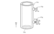
- the holding portion 71h may be provided with a plunger 77p and a knob bolt 77q.
- the first portion 65A of the structure 65 can move in the vertical direction (second direction D2). Thereby, for example, the first portion 65A can be pulled out (see FIG. 3A).
- the first portion 65A of the structure 65 is provided with a hole 65Ah (or a recess) into which the tip of the plunger 77p is inserted.
- the plunger 77p has a force applied to the hole 65Ah by a spring.
- the tip of the plunger 77p is in the hole 65Ah.
- the tip of the plunger 77p comes out of the hole 65Ah.
- the first portion 65A can be pulled out.
- the direction of the second portion 65B of the structure 65 is changed, and the first portion 65A is inserted into the holding portion 71h (see FIG. 3(b)).
- the second portion 65B of the structure 65 is in the second state ST2 (the angle between the first direction D1 and the third direction D3 is substantially 0 degrees or substantially 180 degrees).
- the plunger 77p is pushed toward the hole 65Ah by the spring, the tip of the plunger 77p enters the hole 65Ah.
- the vertical movement of the first portion 65A of the structure 65 is fixed.
- the knob bolt 77q rotates, for example.
- the first portion 65A is fixed by turning the knob bolt 77q.
- FIG. 4 to 6 are schematic perspective views illustrating a part of the bed apparatus according to the embodiment.
- a cross bar 71b is provided at the lower end of the holding portion 71h.
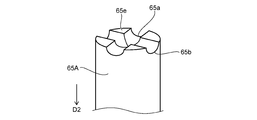
- first portion 65A is illustrated upside down.
- a plurality of grooves (first groove 65a and second groove 65b) are provided at the lower end 65e (upper end in FIG. 5) of the first portion 65A.
- the extending direction of the first groove 65a intersects the extending direction of the second groove 65b.
- the two extending directions are orthogonal.
- such a first portion 65A is inserted into the holding portion 71h.
- One of the first groove 65a and the second groove 65b fits into the cross bar 71b.
- the first state ST1 is obtained.
- the second groove 65b fits into the cross bar 71b, the second state ST2 is obtained.
- the number of the plurality of grooves is arbitrary.
- the angle between the plurality of grooves is arbitrary.
- the difference between the first angle and the second angle may be other than 90 degrees.
- FIG. 7 is a schematic perspective view illustrating one operating state of the bed apparatus according to the embodiment.
- the second frame 72 back bottom 70a
- the first side rail 61 moves following the movement of the second frame 72.
- the first side rail 61 is a follow-up type side rail.
- the first side rail 61 includes a first recess 61a.
- the first recess 61a can support the weight of the user of the bed apparatus 110.
- one surface of the first recess 61a is close to the direction along the floor surface (horizontal direction). The user can easily put his/her hand on the first recess 61a. This facilitates leaving the bed.
- Such a first side rail 61 is on the head side of the bed apparatus 110.
- the structure 65 is on the foot side of the bed apparatus 110.
- the user can easily leave the floor between the first side rail 61 and the structure 65 (in this example, the portion of the second side rail 62).
- the right hand of the user grasps the first recess 61a.
- the left hand of the user grips the second portion 65B of the structure 65. You can encourage you to get out of bed.
- the first side rail 61 when the first side rail 61 is in the back-raised state (when the first side rail 61 rises with the base frame 75B as a reference), at least a part of the first recess 61a of the first side rail 61 is Along the direction in which the frame 75B extends.
- the first side rail 61 may further include a second recess 61b.
- various wires (including tubes) of the medical device are inserted into the second recess 61b. It is easy to provide safe medical care.
- the first side rail may further include a third recess 61c.
- the bed controller 68 is held in the third recess 61c.
- the bed controller 68 is operated by a user or a caregiver to control, for example, raising the back or raising the legs.
- the angle and height of the second frame 72 may be controlled by operating the bed controller 68.
- the bed apparatus 110 may be provided with a load cell or the like, and the weight of the user may be measured.
- the measurement result and the like may be displayed on the display unit of the bed controller 68 or the like.
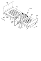
- FIG. 8 is a schematic perspective view illustrating the bed apparatus according to the embodiment.
- the bed apparatus 111 according to the embodiment includes a first frame 71 and a structure body 65.
- the bed apparatus 111 includes a headboard 78A, a footboard 78B, and the like.
- a back bottom 70a, a knee bottom 70b, a foot bottom 70c and the like are provided.
- the bed apparatus 111 may include a base frame 75B, a mattress 78M (see FIG. 1A), and the like. Below, an example of a portion of the bed apparatus 111 different from the bed apparatus 110 will be described.
- the first frame 71 includes a portion extending in the first direction D1.
- the portion extending in the first direction D1 corresponds to a part of the frame body 71r (see FIG. 1C).
- the frame body 71r includes a portion along the width direction Dw and a portion along the length direction Dh (see FIG. 1C).
- One of these portions of the frame body 71r corresponds to the "portion extending in the first direction D1".
- the bed apparatus 111 also includes a holding portion 71h.
- the holding portion 71h is connected to the frame body 71r.
- the structure 65 can have the first state ST1 and the second state ST2.
- FIG. 8 illustrates the second state ST2.
- the first angle in the first state ST1 is different from the second angle in the second state ST2.
- the first state ST1 it is possible to prevent the user from falling off the bed apparatus 110.
- the second state ST2 the user can easily get out of bed by adding weight to the second portion 65B.
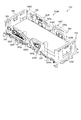
- FIG. 9 is a schematic perspective view illustrating the bed apparatus according to the embodiment.
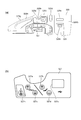
- the bed apparatus 310 includes a right head side rail 320, a right foot side rail 330, a left head side rail 340, a left foot side rail 350, a headboard 360, and a footboard 370.
- the side rails are provided, for example, on the frame 390F of the bed 310B.
- a bottom (not shown in FIG. 9) is provided on the frame 390F of the bed 310B, and a mattress 390M is provided thereon.
- the bed 310B user can lie on the mattress 390M.
- the bed apparatus 310 is used, for example, in a hospital, a care facility, a home, or the like.
- the bed device 310 is, for example, an electric bed.
- the bed apparatus 310 can be operated by the user of the bed 310B, a caregiver, or the like.
- the angles of the head right side rail 320 and the head left side rail 340 can be changed.
- the back can be raised or the back can be lowered.
- the angle of the back bottom 70a see FIG. 17B
- the heights of the right foot side rail 330 and the left foot side rail 350 can be changed.
- the right foot side rail 330 and the left foot side rail 350 are at high positions, for example, it is possible to prevent the user from falling from the bed 310B.
- the right foot side rail 330 and the left foot side rail 350 are in the low position, for example, the user easily leaves the bed 310B from above the right foot side rail 330 and the left foot side rail 350.
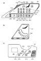
- the head right side rail 320 includes an outer side surface 320F and an inner side surface 320G.
- the foot right side rail 330 includes an outer side surface 330F and an inner side surface 330G.
- the left side rail 340 includes an outer side surface 340F and an inner side surface 340G.
- the left side rail 340 includes an outer side surface 350F and an inner side surface 350G.
- switches and the like are provided on the outer side surface 320F and the inner side surface 320G of the head right side rail 320, and the outer side surface 340F and the inner side surface 340G of the head left side rail 340.
- the switches on the outer surface are designed, for example, to be conveniently operated by a caregiver or health care professional (eg, doctor, nurse or physiotherapist, etc.).
- Various switches and the like are also provided on these inner surfaces.
- the switches on the inner surface are designed, for example, to be conveniently operated by the user of bed 310B. Examples of these switches will be described later.
- Hand rails 325g, 335g, 345g, and 355g are provided on the upper portions of the right head side rail 320, the right foot side rail 330, the left head side rail 340, and the left foot side rail 350, respectively.
- the vertical width of these handrails is narrower on the inside than on the outside. Thereby, for example, a user can easily grab these handrails.
- the width of the upper surface of the hand rails 335g and 355g is designed to be wide. The user can sit on these upper surfaces (end sitting position). Thereby, for example, when the user is sitting at the end, the back of the thigh does not hurt.
- a recess is provided on the outer surface 320F of the right side rail 320 and the outer surface 340F of the left side rail 340.
- the bed operation device 380 can be attached to this recess. Further, the bed operating device 380 can be attached to the outer surface 370F of the footboard 370. The bed operation device 380 will be described later.
- FIG. 10A to 10C are schematic views illustrating a part of the bed apparatus according to the embodiment.
- a through hole 325h is provided in the upper portion of the head right side rail 320.
- a handrail 325g is formed by the through hole 325h.
- a convex portion 325a On the upper portion of the right side rail 320, a convex portion 325a, a concave portion 325b, a head side convex portion 325c, and a head side concave portion 325d are further provided.
- the convex portion 325a can be used, for example, as a support portion that supports the body of the user.
- the recess 325b can be used, for example, as a support portion that supports the body of the user.
- the user can easily grab the head side convex portion 325c. For example, when raising or lowering the back, it is easy to support the user's body by the head side convex portion 325c.
- a through hole is provided in the head-side convex portion 325c. Thereby, the head side convex part 325c can be used as a handrail.
- ⁇ Various medical lines can be inserted in the head side recess 325d. Easy to stabilize various lines. Various lines for medical use include cables or tubes, such as ventilators and various ME devices. By passing various lines through the head-side recess 325d, for example, it is possible to prevent these lines from being entangled.
- a switch part 323, a goniometer 324, a through hole 325e (for example, a hook part), and a lower through hole 325f (for example, a Harun bag hook) are provided on an outer surface 320F of the right side rail 320 on the head side.
- the bed operation device 380 can be suspended in the through hole 325e.
- the Harun bag can be hung in the lower through hole 325f.
- a trash can or the like can be hung in the lower through hole 325f.
- the hole 328h is provided below the through hole 325e.
- the cable of the bed operating device 380 can pass through the hole 328h.
- the cable is electrically connected to the connector provided in the bed apparatus 310 through the hole 328h. It is possible to prevent the cable from getting on the floor.
- the cable can be shortened.
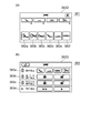
- FIG. 10B illustrates the switch unit 323.
- the switch unit 323 is, for example, a membrane switch (for example, a membrane switch for medical workers).
- the switch unit 323 includes switches 323a to 323q.
- the angle between the back bottom 70a and the knee bottom 70b does not become extremely small, it is possible to prevent the user from having too much abdominal pressure while maintaining a comfortable posture. For example, if the user tilts the knee without raising it, the user may slip down. When the knee bottom 70b is raised above the horizontal angle, the user is prevented from sliding down. By “cardiac lowering", the angle between the back bottom 70a and the knee bottom 70b does not become extremely small toward the state where the back angle is 0 degrees, the knee angle is 0 degrees, and the inclination angle is 0 degrees. In this state, the bed 310B operates while keeping the knee bottom 70b raised above the horizontal angle.
- the back angle is 0 degree and the knee angle is 0 degree at first.
- the back angle becomes 5 degrees and the knee angle becomes 0 degrees.
- the back angle becomes 15 degrees and the knee angle becomes 10 degrees.
- the back angle becomes 30 degrees, the knee angle becomes 25 degrees, the back angle becomes 50 degrees, and the knee angle becomes 25 degrees.
- the back angle becomes 70 degrees and the knee angle becomes 0 degrees.
- the back angle and the knee angle increase in conjunction with each other up to the middle. Above a certain back angle, the knee angle decreases toward 0 degrees.
- the back angle is 70 degrees and the knee angle is 0 degrees at the beginning.
- the back angle becomes 50 degrees and the knee angle becomes 25 degrees.
- the back angle becomes 30 degrees and the knee angle becomes 25 degrees.
- the back angle becomes 15 degrees and the knee angle becomes 20 degrees.
- the back angle becomes 0 degree and the knee angle becomes 5 degrees. After that, the back angle becomes 0 degree and the knee angle becomes 0 degree.
- the switches 323c to 323g for “up” are located above the switches 323h to 323l for “down”.
- the user of the bed 310B may unintentionally touch the switch of the switch unit 323.
- the user of the bed 310B is more likely to touch the upper portion than the lower portion. Since the switches 323c to 323g for "raising" are on the upper side, even when the user mistakenly touches the upper portion, the risk can be further suppressed as compared with the case of touching the switches 323h to 323l.
- CPR lowering When the switch 323m is pressed, "CPR lowering" is performed.
- the bed state In the “CPR lowering”, the bed state is suitable for CPR (Cardio Pulmonary Resuscitation).
- CPR lowered In the “CPR lowered” state, the knee bottom 70b and the foot bottom 70c become flat.
- CPR lowering the floor height of the bed 310B is lowered.
- the tilt angle In the tilted state, the tilt angle is also 0 degree.
- the operation sequence is as follows. The back angle is set to 0 degree (while the back bottom 70a is being moved, the knee bottom is also brought close to 0 degree). Next, the tilt angle is set to 0 degree. Next, lower the height. Next, the knee angle is set to 0 degree.
- the bed 310B may be in the lowest floor height state.
- a position (temporary stop height) at which the bed 310B is temporarily stopped may be provided by an operation of “lowering the height”. If the height is higher than the temporary stop height in the state before the “CPR lowering”, the height of the bed 310B is temporarily set to the stop height by the “CPR lowering”. Once at stop height, the distance from the floor to the top of the bottom is about 42 cm.
- the switch 323m when the switch 323m is "long pressed", “CPR lowering” is performed.
- the “long press” time is, for example, 2 seconds or more.
- the switch 323m when the switch 323m is “pressed twice", “CPR down” is performed.
- the switch 323m is “pressed twice", the time between "pressing first” and “pressing second” is within 5 seconds.
- CPR lowering is an electric CPR operation. In addition to this, a manual CPR operation may be performed.
- the switch 323n is a “nurse call”. When the switch 323n is pressed, a nurse call is made. Information is transmitted to the nurse call system.
- the switch unit 323 includes displays 323r to 323t.
- the display 323r displays the remaining battery level.
- the display 323s is lit (for example, orange) when the floor height is not the lowest.
- the display 323s is turned off when the floor height is the lowest.
- the display 323t displays an error. At the normal time, the display 323t disappears.
- the "U system abnormality” occurs, lighting for 1 second and turning off for 1 second are repeated.
- “H system abnormality” lighting for 0.2 seconds and turning off for 0.2 seconds are repeated.
- the operation by the switch unit 323 (for example, the membrane switch for medical workers) on the outer side surface 320F is prioritized over the operation by the switch unit (for example, the user membrane switch) described below provided on the inner side surface 320G.
- the switch unit for example, the user membrane switch
- FIG. 10C illustrates the goniometer 324 provided on the outer surface 320F of the right side rail 320 on the head side.
- a recess is provided on the right side rail 320 of the head, and a sphere (for example, a metal ball) provided with the recess serves as an angle meter 324.
- a sphere for example, a metal ball
- the angle display on the display unit 324a of the angle meter 324 changes according to the position of the sphere.
- the outline of the back angle can be known.
- FIG. 11A and 11B are schematic views illustrating a part of the bed apparatus according to the embodiment.
- a recess 328 is provided on the inner side surface 320G of the right head side rail 320.
- the recess 328 can be used as a hook.
- a hole 328h is provided below the recess 328.
- the switch portion 327 is provided on the inner surface 320G.
- the switch unit 327 is, for example, a membrane switch (for example, a user membrane switch or a patient membrane switch).
- the switch unit 327 includes switches 327a to 327d.
- the switch unit 327 may include a switch 327n.
- a switch 327n is provided on the inner surface 320G.
- the switch 327n is a “nurse call”.
- a USB terminal 327u is provided on the inner surface 320G.
- a USB plug can be inserted into the USB terminal 327u for charging.
- the above-described configuration of the head right side rail 320 is also applied to the head left side rail 340.
- 12A to 12C are schematic views illustrating a part of the bed apparatus according to the embodiment.
- 12A and 12B illustrate the switch unit 343 and the goniometer 344 provided on the outer surface 340F of the left side rail 340 on the head side.
- the switch unit 343 includes switches 343a to 343q.
- the switches 343a to 343q have the same functions as the switches 323a to 323q.
- the switch unit 343 includes displays 343r to 343t.
- the displays 343r to 343t have the same functions as the displays 323r to 323t.
- FIG. 12B illustrates the goniometer 344.
- the goniometer 344 has the same structure and function as the goniometer 324.
- the display section 344a of the goniometer 344 can provide an overview of the back angle.
- a switch unit 347 is provided on the inner side surface 340G (see FIG. 9) of the left side rail 340 of the head.
- the switch unit 347 has the same structure and function as the switch unit 327.
- the switch unit 347 includes switches 347a to 347d.
- the switches 347a to 347d have the same functions as the switches 327a to 327d.
- the switch 347n and the USB terminal 347u are provided on the inner surface 320G.
- the USB terminal 347u may be omitted.
- FIG. 13A and 13B are schematic views illustrating a part of the bed apparatus according to the embodiment.
- a hand rail 335g is provided on the right side rail 330 of the foot.
- the handrail 335g is formed by the through hole 335h.
- a lower through hole 335f (for example, Harun bag hook) is provided in the lower portion of the right side rail 330 of the foot.
- a Harun bag or the like can be hung in the lower through hole 335f.
- An angle meter 334 is provided on the outer surface 330F of the right side rail 330 of the foot (see FIG. 13B).
- the goniometer 334 has a structure similar to that of the goniometer 324.
- the display unit 334a of the goniometer 334 can provide an overview of the angle.
- FIG. 14 is a schematic view illustrating a part of the bed apparatus according to the embodiment. As shown in FIG. 14, the handrail 335g is obtained by the through hole 335h formed in the right side rail 330 of the foot.
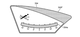
- FIG. 15 is a schematic diagram which illustrates a part of bed apparatus which concerns on embodiment.
- FIG. 15 illustrates the goniometer 354 provided on the outer surface 350F of the left side rail 350.
- the goniometer 354 has a structure similar to that of the goniometer 324.
- the display unit 354a of the goniometer 354 can provide an overview of the angle.
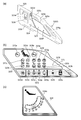
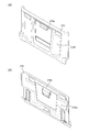
- FIG. 16A and 16B are schematic views illustrating a part of the bed apparatus according to the embodiment.
- a through hole 375e (for example, a hook portion) is provided on the outer surface 370F of the footboard 370.
- the bed operation device 380 can be suspended in the through hole 375e.
- the through hole 375e penetrates the inner side surface 370G of the footboard 370.
- the bed operation device 380 can display various settings regarding the bed 310B and the weight of the user.
- a “home button” is provided as a “physical button” in the bed operation device 380.
- An example of the bed operating device 380 will be described later.
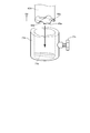
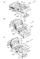
- 17(a) to 17(c) are schematic perspective views illustrating the operation of the bed apparatus according to the embodiment. These figures exemplify the state when the mattress 390M is not provided.
- the frame 390F is attached to the base frame 390B.
- a back bottom 70a back section
- a knee bottom 70b upper leg section
- a foot bottom 70c lower leg section
- the like are provided on the frame 390F.
- a waist bottom 70e is provided.
- the casters 390C may be provided on the base frame 390B.
- the angle (tilt) of the frame 390F can be changed.
- the tilt may include a left-right tilt as well as a front-back tilt.
- the respective angles of the back bottom 70a, the knee bottom 70b, and the foot bottom 70c can be changed.
- the angles of the head right side rail 320 and the head left side rail 340 change according to the change of the angle of the back bottom 70a.
- the head right side rail 320 and the head left side rail 340 are follow-up side rails.
- the state of FIG. 17B corresponds to the Cardiac position.
- the foot right side rail 330 and the foot left side rail 350 are in the “upper state”.
- the foot right side rail 330 and the foot left side rail 350 can be in the “down state”.
- the height of the bed 310B can be changed.
- the height corresponds to the distance between the upper surface of the bed 310B (for example, the upper surface of the bottom) and the floor surface, for example.
- FIG. 18A and 18B are schematic perspective views illustrating the usage state of the bed apparatus according to the embodiment.
- FIG. 18A illustrates a state where the bed 310B is low.
- a caregiver or the like 398 (for example, a caregiver or a medical worker) can operate the bed operation device 380 with the bed operation device 380 removed from the hook portion (for example, the through hole 325e of the right side head rail 320).
- FIG. 18B illustrates a state in which the bed 310B is high.
- a caregiver 399 or the like can operate the bed operation device 380 while the bed operation device 380 is attached to the hook portion.
- the bed operation device 380 is attached to, for example, three hook portions.
- the three hook portions are a through hole 325e of the head right side rail 320, a through hole 345e of the head left side rail 340, and a through hole 375e of the foot board 370.
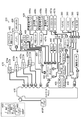
- FIG. 19 is a schematic view illustrating the bed apparatus according to the embodiment.
- a control box 410 is provided in the bed apparatus 310.
- various devices are provided in the bed device 310.
- Various devices include a junction box 420, a membrane switch 430, a leglight 440, a side rail sensor 450 (SR sensor), a caster lock sensor 455 (CL sensor), a nurse call 457a, a nurse call 457b, a nurse call relay unit 458, a scale.
- the unit 460, the load cell 465, the actuator 470, the battery 475, etc. are included. Some of the various devices may be omitted.
- the control box 410 can be connected to various devices. The connection between the control box 410 and various devices is made directly or via the junction box 420.
- the control box 410 controls the bed operation and various functions.
- the control box 410 serves as a master for serial communication in the bed apparatus 310.
- the control box 410 is provided with a plug 410P (for example, a 3-pin plug). Electric power is supplied to the control box 410 from the plug 410P. Electric power is supplied from the control box 410 to various devices.
- a plug 410P for example, a 3-pin plug. Electric power is supplied to the control box 410 from the plug 410P. Electric power is supplied from the control box 410 to various devices.
- the junction box 420 relays the connection between the control box 410 and various other devices.
- the membrane switch 430 includes membrane switches 430a and 430b for medical personnel. These membrane switches correspond to the switch units 323 and 343. Membrane switch 430 includes patient membrane switches 430c and 430d. These membrane switches correspond to the switch units 327 and 347.
- the medical worker membrane switch 430a and the patient membrane switch 430c are connected to the junction box 420 via the relay unit 431a.
- the membrane switch 430b for medical workers and the membrane switch 430d for patients are connected to the junction box 420 via the relay unit 431b.
- Bed operation buttons are provided on the membrane switches 430a and 430b for medical staff.
- the bed operation buttons are cardiac operation buttons (for example, interlocking operation buttons), extension/reverse extension buttons, kind motion operation buttons (for example, other interlocking operation buttons), CPR buttons, nurse calls. Includes buttons, patient membrane switch inhibit buttons, and all switch inhibit buttons. The operation described with respect to the switch units 323 and 343 is performed by these bed operation buttons.
- Bed operation buttons are provided on the patient membrane switches 430c and 430d.
- the bed operation buttons include the back bottom operation button, the knee bottom operation button, and the nurse call button.
- the patient membrane switches 430c and 430d may include charging terminals and the like.
- the bed operation button is provided at an intermediate position in the vertical direction. If the bed operation button is at the bottom, it is difficult to operate. If the bed operation button is at the top, it may be operated accidentally. Since the bed operation button is located at an intermediate position in the up-down direction, the operation becomes easy, and erroneous operation can be suppressed.
- the footlight button corresponds to the switches 323q and 343q.
- the footlight 440 illuminates.
- the foot lamp 440 illuminates the floor surface from the end of the bed 310B.
- the leg lights 440 are provided, for example, one on each side of the bed 310B.
- the leg lights 440 are provided, for example, at the left and right ends on the back side (lower side) of the waist bottom 70e.
- the leg lights 440 may be provided in other parts such as the back bottom 70a, the knee bottom 70b, and the foot bottom 70c (see FIG. 17B and the like).
- the leglight 440 is repeatedly turned off, dimly turned on, brightly turned on, and turned off.
- the leg light 440 is turned on by a medical staff. For example, when the user frequently goes to the toilet, the medical staff turns on the leglight 440 before the user goes to bed. For example, when a bed leaving is detected, or when a nurse call occurs, the medical staff turns on the leglight 440.
- the leg light 440 is turned on. At this time, the room is often dark. When the leglights 440 suddenly turn on brightly, people sleeping in the vicinity are annoyed. By turning on the light at first, annoyance is suppressed.
- the side rail sensor 450 detects whether or not each side rail is raised.
- Four siderail sensors 450 are provided.
- the four side rail sensors 450 include a head right side rail sensor, a head left side rail sensor, a foot right side rail sensor, and a foot left side rail sensor.
- the detection result is displayed on the terminal of the nurse station, for example.
- the detection result may be displayed on the bed operation device 380.
- a warning sound may be generated based on the detection result.
- As the side rail sensor 450 for example, a magnetic sensor or an atmospheric pressure sensor is used. Other sensors may be used as the side rail sensor 450.
- the caster lock sensor 455 detects whether or not the caster 390C is locked.
- a magnetic sensor is used as the caster lock sensor 455, for example.
- the caster 390C is provided with a bar or the like interlocking with the lock or unlock of the caster 390C.
- the locked state of the caster 390C can be detected by detecting the state of the bar.
- the detection result of the caster lock sensor 455 is displayed on the terminal of the nurse station, for example.
- the detection result may be displayed on the bed operation device 380.
- a warning sound may be generated based on the detection result of the caster lock sensor 455.
- the nurse call 457a is connected to the junction box 420.
- the nurse call 457b is connected to the nurse call relay unit 458.
- the nurse call relay unit 458 enables cooperation with a nurse call (for example, nurse call 457b) provided in hospitals and facilities.
- Nurse calls 457a and 457b are domestic or foreign nurse calls.
- the nurse call 457a is made in a foreign country.
- the nurse call 457b is made in Japan.
- the load cells 465 are provided at the four corners of the bed 310B. Four load cells 465 are used.
- the load cell 465 and the scale unit 460 can measure the weight of the user.
- the actuator 470 includes a height changing actuator 470a (“HLACT”), a knee bottom 70b actuator 470b (“knee ACT”), a back bottom 70a actuator 470c (CPR-equipped “back ACT”), and The height changing actuator 470d (“HLACT”) and the like are included.
- the actuators 470a and 470d include load sensors.
- the actuator 470c for the back bottom 70a includes a mechanical mechanism (hereinafter, referred to as a manual CPR mechanism) for performing a lowering operation manually.
- the manual CPR mechanism allows the back bottom 70a to be manually lowered in an emergency.
- a dedicated lever or the like is provided, and by operating this lever, the back bottom 70a can be manually lowered to obtain a posture for CPR.
- the brake plate of the actuator 470c for the back bottom 70a can be manually displaced. As a result, the brake of the actuator 470c is released, and the back bottom 70a is lowered by its own weight.
- the actuator 470 serves as a drive source for adjusting the movable part included in the bed 310B.
- the actuator 470 operates the movable portion via the link mechanism or the like by the operation of the telescopic rod.
- a position sensor is provided for each of the actuators. The position information is read by the control box 410.
- the load sensor of the actuator 470 may determine the movement of the user (patient, etc.) on the bed 310B (including, for example, leaving the bed).
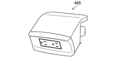
- the battery 475 supplies electric power during a power failure or during transportation of the bed 310B.
- the desired operation can be obtained even in the situation where there is no power supply.
- a switch for charging/not charging the battery 475 may be provided. Charging may be possible as long as power (AC power) is supplied to the bed 310B regardless of the state of the changeover switch.
- the bed apparatus 310 when the bed apparatus 310 is driven by an AC power source, power is supplied from the control box 410 to the battery 475, the air mattress control unit 482 and the USB charger 488 (see FIG. 19).
- power is supplied from the battery 475 to the control box 410, the air mattress control unit 482, and the USB charger 488.
- the bed 310B When power is not supplied from the AC power supply and power is not supplied from the battery 475, the bed 310B does not operate.
- a sleep sensor 481, an air mattress control unit 482, and a bed operation apparatus 380 are provided in the bed apparatus 310.
- a hand switch 483 may be provided in the bed apparatus 310.
- the sleep sensor 481 measures the sleep status of the user (patient, etc.) of the bed 310B.
- the sleep status measurement result and the sleep history may be output (for example, displayed) to the bed operation device 380.
- control box 410 is provided with a connector for the air mattress control unit 482.
- the interlocking operation may be performed according to the posture of the bed 310B.
- the interlocking operation may differ depending on the type of air mattress.
- the bed operation device 380 may set and change the operation of the air mattress.
- the bed device 310 is further provided with an auxiliary outlet 485.
- two auxiliary outlets 485 are provided.
- the auxiliary outlet 485 is a plug receiving device.
- the auxiliary outlet 485 includes a plug 485P.
- the plug 485P is a plug that meets medical standards.
- the plug 485P is a 3-pin plug.
- the plug 485P is provided separately from the plug 410P of the control box 410.
- the bed apparatus 310 may include a USB charger 488 (see FIG. 19).
- the USB charger 488 corresponds to the USB terminal 327u (or 347u).
- the USB charger 488 supplies power to a device compatible with USB charging.
- the number of ports of the USB charger 488 may be one.
- the output rating of the USB charger 488 is DC 5V/1A.
- the port is provided on the patient membrane switch 430c on the right siderail.
- the bed device 310 may include an error display LED.
- the error display LED corresponds to the displays 323t and 343t.
- the bed device 310 may detect that the user of the bed 310B has left the bed. For example, leaving the bed is detected by the load cell 465. For example, the leaving sensor is detected by a load sensor incorporated in the actuator. Information about leaving the bed is transmitted to the nurse call system and output to the terminal of the nurse station. The information regarding leaving the bed may be output to the bed operation device 380. The output of information regarding leaving the bed may include, for example, a visual stimulus such as a lamp or an auditory stimulus such as a warning sound.
- the bed operation device 380 is connected to the bed 310B.
- the bed operation device 380 can set and display the settings related to the bed 310B. It is possible to switch the display language on the bed operation device 380. For example, it is possible to display in Japanese, English, Chinese or Portuguese.
- the bed operation device 380 is attached to, for example, the left and right side rails or the footboard 370.
- the maximum number of bed operation devices 380 provided in the bed device 310 is 3, for example.
- one bed operation device 380 or one hand switch 483 (described later) is connected to the bed 310B.
- one bed operation device 380 and one hand switch 483 are connected to the bed 310B.
- two bed operating devices 380 are connected to the bed 310B.
- two bed operation devices 380 and one hand switch 483 are connected to the bed 310B.
- three bed operation devices 380 are connected to the bed 310B.
- FIG. 20A and 20B are schematic views illustrating a part of the bed apparatus according to the embodiment.
- FIG. 20A illustrates the bed operating device 380 mainly provided on the head side rail (the head right side rail 320 or the head left side rail 340).
- the bed operation device 380 includes a display input unit 380D.
- the bed operation device 380 is provided with a home button 380h.
- various displays can be made on the display input unit 380D.
- the display input unit 380D can display the posture of the bed 310B and the weight of the user.
- the display input unit 380D allows setting of the bed leaving sensor.
- a display regarding the sleep sensor 481 can be performed by the display input unit 380D.
- the display input unit 380D allows the operation of the air mattress. An error can be displayed by the display input unit 380D.
- FIG. 21A and 21B are schematic views illustrating a part of the bed apparatus according to the embodiment.
- FIG. 21A illustrates the bed operation device 380 mainly provided on the footboard 370.
- the bed operation device 380 includes a display input unit 380D.
- the bed operation device 380 is provided with an up button 380a, a down button 380b, and a CPR button 380c.
- the up button 380a or the down button 380b moves up or down the movable part of the bed 310B.
- the CPR button 380c the posture is changed to CPR.
- various displays can be made on the display input unit 380D.
- the display input unit 380D can operate the bed 310B.
- the bed operation includes, for example, cardiac operation, tilting operation, interlocking operation (kind operation), raising and lowering the back, raising and lowering the knee, and raising and lowering the height.
- the display input unit 380D can display the weight of the user.
- the display input unit 380D allows setting of the bed leaving sensor.
- a display regarding the sleep sensor 481 can be performed by the display input unit 380D.
- the display input unit 380D allows the operation of the air mattress. An error can be displayed by the display input unit 380D.
- FIG. 22 is a schematic view illustrating a part of the bed apparatus according to the embodiment.
- FIG. 22 illustrates the hand switch 483.
- the hand switch 483 includes switch pairs 483a to 483d.
- Switch pair 483a includes a switch for raising or lowering for "interlocking" operation.
- Switch pair 483b includes a switch for raising or lowering for "back raising” movement.
- Switch pair 483c includes a switch for raising or lowering for a "foot lift” action.
- the switch pair 483d includes a switch for raising or lowering regarding the “height” changing operation.
- the angle or height may be displayed on the display portion 483D of the hand switch 483.
- the hand switch 483 is connected to, for example, the control box 410 by a cable 483e or the like.
- FIG. 23 is a schematic perspective view illustrating a part of the bed apparatus according to the embodiment.
- FIG. 23 illustrates an auxiliary outlet 485 (for example, a plug receiving device). Plugs of electronic devices used around the bed 310B can be connected to the auxiliary outlet 485.
- the plug 485P of the auxiliary outlet 485 is provided separately from the plug 410P of the control box 410.
- the auxiliary outlet 485 has two sets of plug receivers (plug insertion holes). The two sets of plug receivers are arranged side by side.
- FIG. 24 is a schematic view illustrating a part of the bed apparatus according to the embodiment.
- FIG. 24 illustrates the back bottom 70a, the knee bottom 70b, the foot bottom 70c, and the waist bottom 70e.
- the angles of the back bottom 70a, the knee bottom 70b, and the foot bottom 70c can be changed. It is controlled so that the angle between the bottoms does not fall below a predetermined value (for example, 90 degrees).
- a predetermined value for example, 90 degrees
- the angle between the line connecting the lower end of the back bottom 70a and the upper end of the knee bottom 70b (broken line in FIG. 24) and the back bottom 70a is controlled to be a predetermined value (for example, 90 degrees) or less.
- the angle is made equal to or less than a predetermined value.
- the operation angle of the back bottom 70a is, for example, 0 degrees to 70 degrees.
- the operation angle of the knee bottom 70b is 0 degrees or more and 25 degrees or less.
- the operating range of "height" is, for example, 43 cm.
- the floor height may vary depending on the bed frame. The floor height range is, for example, 30 cm to 73 cm, 32.5 cm to 75.5 cm, or 35 cm to 78 cm.
- the operating angle of the bottom tilt is -15 to 15 degrees.
- the tilting operation is performed after the height is adjusted to the height of “minimum floor height+3 cm”.
- the operations are performed in the following order. At that time, if the simultaneous operation is possible, the simultaneous operation may be performed.
- the stroke of the actuator 470c (“back ACT”) for the back bottom 70a is operated to the lower limit.
- the lower limit of the actuator 470c is reached within 30 seconds after the button for the electric CPR operation is pressed.
- the tilting operation is performed and the tilt angle becomes 0 degree.
- height adjustment is performed and the height becomes the minimum floor height.
- the minimum floor height is, for example, “temporary stop height”.
- the knee bottom 70b is moved to 0 degree.
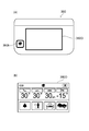
- FIG. 25A and 25B are schematic views illustrating a part of the bed apparatus according to the embodiment. These drawings exemplify the display input unit 380D of the bed operation device 380.
- FIG. 25A illustrates a case where the display input unit 380D is the bed operation screen 381.
- FIG. 25B illustrates a case where the display input unit 380D is the actuator individual operation prohibition screen 383 (bed setting screen).
- buttons 382a to 382f are provided. These buttons are, for example, input acceptance areas in the touch input device. By touching these buttons, bed operation is performed.
- the cardiac operation is performed by the button 382a.
- the tilt operation is performed by the button 382b.
- a linked operation (“kind operation”) is performed by the button 382c.
- the back movement is performed by the button 382d.
- a knee operation (change of knee angle) is performed by the button 382e.
- a height operation (change of height) is performed by the button 382f. For example, when raising the height of the bed 310B, pressing the button 382d and then pressing the lift button 380a moves the bed 310B.
- the bed 310B moves while pressing the up button 380a. For example, when lowering the height of the bed, if the button 382f is pressed and then the lowering button 380b is pressed, the height of the bed 310B is lowered while the lowering button 380b is being pressed.
- the display input unit 380D can be moved to the actuator individual operation prohibition screen 383 (bed setting screen).
- the actuator individual operation prohibition screen 383 bed setting screen.
- the back motion, knee motion, height motion, and tilt motion can be individually prohibited.
- the display input area 383b By operating the display input area 383b, all operations can be prohibited or the operation prohibition can be released.
- the display input area 383c By operating the display input area 383c, the operation of the hand switch 483 can be prohibited or the operation prohibition can be released.
- back movements are prohibited, cardiac movements, interlocking movements and back movements are prohibited.
- the Cardiac movement, the interlocking movement, and the knee movement are prohibited.
- the height motion is prohibited, the Cardiac motion, the tilt motion, and the height motion are prohibited.
- the tilting motion is prohibited, the Cardiac motion and the tilting motion are prohibited.
- the actuator 470 (such as 470a to 470d (see FIG. 19)) may be selectively (individually) “inhibited”. The release of the “operation prohibited” of the actuator 470 is released by the bed operation device 380.
- the prohibition of the operation of the actuator 470, the prohibition of the operation of the hand switch 483, or the prohibition of all the operations are managed independently. For example, when the individual operation of the actuator 470 is prohibited, the “all operation prohibited” is set, and thereafter, even if the “all operation prohibited” is released, the individual operation prohibition of the actuator 470 remains.
- a buzzer sounds and the prohibit LED (eg, display 323t and 343t) of the membrane switch blinks. If you don't hear a buzzer, you don't know if the button is banned or broken. A buzzer sounds to indicate that the button is prohibited.
- the hand switch 483 When the prohibited button on the hand switch 483 is pressed, the hand switch 483 sounds. When a prohibited button on the membrane switch is pressed, for example, the junction box 420 sounds.
- the membrane switch for medical staff or the bed operation device 380 By operating the membrane switch for medical staff or the bed operation device 380, the operation of the membrane switch for patients and the hand switch 483 can be disabled. The operation prohibition can be released if the medical worker membrane switch or the bed operation device 380 is connected.
- All operations can be prohibited by operating the membrane switch for medical staff or the bed operating device 380 (“All operations prohibited”). This operation prohibition can be released if either the membrane switch for medical staff or the bed navigation is connected.
- the bed operation device 380 is not connected to the bed 310B, or if there is a partial failure (communication failure), the “all operations prohibited” is released. In this case, for example, it can be operated by the hand switch 483. If the user does not want to operate it, the hand switch 483 may be removed. When the prohibited button is pressed, a buzzer sounds and the prohibit LED of the membrane switch blinks.
- the operation speed can be changed by operating the display input area 383d illustrated in FIG. 25(b).
- the speed of various operations can be changed in multiple stages (eg, two stages).
- History of various operations of the bed apparatus 310 may be stored.
- the history is stored in a memory such as the control box 410.
- the memory for storing the history may be provided in the junction box 420, the hand switch 483, or the like.
- the memory in which the history is stored may be provided in the bed operation device 380.
- Information about history is not reset by powering on/off.
- the history information includes, for example, the operation history of the control box 410, the operation history of the actuator 470, the operation history of the hand switch 483, the operation content history, the failure history, and the separated floor history.
- the embodiment may include the following configurations.
- (Structure 1) A structure removably attached to a bed device including a holding portion and a first frame including a portion extending in a first direction, The structure is A columnar first portion extending in a second direction intersecting the first direction; A second portion including a portion that is connected to the first portion and extends in a third direction that intersects the second direction; Equipped with The first portion is inserted into the holding portion, and the holding portion holds the structure, A structure in which an angle between the first direction and the third direction is variable when the structure is attached to the bed apparatus.
- the bed device has a length direction and a width direction, the length of the bed device in the length direction is longer than the length of the bed device in the width direction,
- the structure according to configuration 1 or 2 wherein, when the structure is attached to the bed apparatus, a position of the holding portion in the width direction is outside the foot bottom in the width direction.
- the first frame includes an extending portion extending in the first direction, 4.
- the structure according to any one of configurations 1 to 3, wherein the holding part is fixed to the extending part when the structure is attached to the bed apparatus.
- the present invention is not limited to these specific examples.
- the present invention can be similarly implemented by appropriately selecting from a range known to those skilled in the art, and similar effects can be obtained. As long as it is obtainable, it falls within the scope of the present invention.
- plunger 77q... knob bolt, 78A...headboard, 78B...footboard, 78Bu...upper end, 78M...mattress, 110...bed device, D1 to D3...first to third directions, Dh...length direction, Dw...width direction, ST1 to ST4...second 1st to 4th states, 310... Bed device, 310B... Bed, 320... Head right side rail, 320F... Outer surface, 320G... Inner surface, 323... Switch part, 323a-323q... Switch, 323r-323t... Display, 324 ... goniometer, 324a... display part, 325a... convex part, 325b... concave part, 325c... head side convex part, 325d...
- Switch 343r to 343t...display, 344...angle meter, 344a...display section, 345e...through hole, 347...switch section, 347a to 347d...switch, 347n...switch, 347u...terminal, 350...foot left side rail, 350F...outside Side surface, 350G...inner surface, 354...angle meter, 354a...display section, 355g...hand rail, 360...headboard, 370...footboard, 370F...
- Patient membrane switch 431a, 431b... Relay unit, 440... Leglight, 450... Side... Rail sensor, 455... Castor lock sensor, 457a, 457b... Nurse call cooperation, 458... Nurse call relay unit, 460... Scale unit, 465... Load cell, 470... Actuator, 470a-470d... Actuator, 475... Battery, 481... Sleep Sensor, 482... Air mattress control unit, 483... Hand switch, 483D... Display section, 483a-483d... Switch pair, 483e... Cable, 485... Auxiliary outlet, 485P... Plug, 488... Charger
Landscapes
- Health & Medical Sciences (AREA)
- Nursing (AREA)
- Life Sciences & Earth Sciences (AREA)
- Animal Behavior & Ethology (AREA)
- General Health & Medical Sciences (AREA)
- Public Health (AREA)
- Veterinary Medicine (AREA)
- Rehabilitation Therapy (AREA)
- Invalid Beds And Related Equipment (AREA)
Priority Applications (2)
| Application Number | Priority Date | Filing Date | Title |
|---|---|---|---|
| CN201980047299.7A CN113490475A (zh) | 2019-02-27 | 2019-07-30 | 构造体 |
| US17/260,962 US11672355B2 (en) | 2019-02-27 | 2019-07-30 | Structure |
Applications Claiming Priority (2)
| Application Number | Priority Date | Filing Date | Title |
|---|---|---|---|
| JP2019035001A JP7125361B2 (ja) | 2019-02-27 | 2019-02-27 | 構造体 |
| JP2019-035001 | 2019-02-27 |
Publications (1)
| Publication Number | Publication Date |
|---|---|
| WO2020174716A1 true WO2020174716A1 (ja) | 2020-09-03 |
Family
ID=72239305
Family Applications (1)
| Application Number | Title | Priority Date | Filing Date |
|---|---|---|---|
| PCT/JP2019/029759 Ceased WO2020174716A1 (ja) | 2019-02-27 | 2019-07-30 | 構造体 |
Country Status (4)
| Country | Link |
|---|---|
| US (1) | US11672355B2 (enExample) |
| JP (1) | JP7125361B2 (enExample) |
| CN (1) | CN113490475A (enExample) |
| WO (1) | WO2020174716A1 (enExample) |
Cited By (1)
| Publication number | Priority date | Publication date | Assignee | Title |
|---|---|---|---|---|
| US11672355B2 (en) | 2019-02-27 | 2023-06-13 | Paramount Bed Co., Ltd. | Structure |
Families Citing this family (1)
| Publication number | Priority date | Publication date | Assignee | Title |
|---|---|---|---|---|
| JP7185561B2 (ja) * | 2019-02-27 | 2022-12-07 | パラマウントベッド株式会社 | ベッド装置 |
Citations (5)
| Publication number | Priority date | Publication date | Assignee | Title |
|---|---|---|---|---|
| JPS55146130U (enExample) * | 1979-04-05 | 1980-10-21 | ||
| JPH0411026U (enExample) * | 1990-05-22 | 1992-01-29 | ||
| JP2000229020A (ja) * | 1999-02-12 | 2000-08-22 | Paramount Bed Co Ltd | ベッドにおける側柵の取り付け構造 |
| JP2003033256A (ja) * | 2001-07-24 | 2003-02-04 | France Bed Co Ltd | ベッド装置 |
| JP2015202378A (ja) * | 2014-04-16 | 2015-11-16 | パナソニックIpマネジメント株式会社 | ベッド |
Family Cites Families (23)
| Publication number | Priority date | Publication date | Assignee | Title |
|---|---|---|---|---|
| JPS5646200Y2 (enExample) | 1977-09-02 | 1981-10-28 | ||
| US4932090A (en) * | 1989-04-12 | 1990-06-12 | Johansson Paul J | Movable support bar |
| NL8901273A (nl) * | 1989-05-22 | 1990-12-17 | Oostwoud Holding B V | Bed. |
| JP2669453B2 (ja) * | 1995-03-01 | 1997-10-27 | パラマウントベッド株式会社 | ベッドにおけるサイドフレーム構造 |
| US6240583B1 (en) * | 1996-12-03 | 2001-06-05 | Hill-Rom, Inc. | Ambulatory assist arm for a bed |
| JP3134995B2 (ja) * | 1998-10-21 | 2001-02-13 | パラマウントベッド株式会社 | ベッドにおける側柵の取り付け構造 |
| JP4604258B2 (ja) * | 2004-05-31 | 2011-01-05 | 株式会社いうら | サイドレール |
| KR100752389B1 (ko) * | 2006-12-20 | 2007-08-27 | 대주건설주식회사 | 틀비계용 난간대 |
| CN201905562U (zh) * | 2010-11-22 | 2011-07-27 | 河北普康医疗设备有限公司 | 帮助病人自主站立的床护栏 |
| CN204105405U (zh) * | 2014-04-11 | 2015-01-21 | 天津融创家具有限公司 | 床 |
| CN203987084U (zh) * | 2014-08-06 | 2014-12-10 | 中国人民解放军第四军医大学 | 一种防坠落床 |
| CN204293428U (zh) * | 2014-12-08 | 2015-04-29 | 张云龙 | 一种麻醉用床体 |
| CN205198334U (zh) * | 2015-08-18 | 2016-05-04 | 河北工业大学 | 一种可旋转医用护理床护栏 |
| JP6552376B2 (ja) * | 2015-10-16 | 2019-07-31 | パラマウントベッド株式会社 | ベッド用側柵の固定部材 |
| CN205144937U (zh) * | 2015-10-22 | 2016-04-13 | 成都江雪医疗器械有限公司 | 一种病床的旋转升降护栏 |
| JP6704305B2 (ja) | 2016-06-24 | 2020-06-03 | パラマウントベッド株式会社 | 補助柵及び寝台装置 |
| CN206621118U (zh) * | 2016-11-11 | 2017-11-10 | 台州市温岭中医医疗中心(集团) | 一种折叠式可倚靠病床护栏 |
| CN108078691A (zh) * | 2018-01-10 | 2018-05-29 | 哈尔滨理工大学 | 一种具有骨折固定功能的楔形锁紧式便携生命支持系统 |
| US11229566B2 (en) * | 2018-06-08 | 2022-01-25 | Arjo Ip Holding Ab | Two-plane, folding patient assist handle |
| CN109124157A (zh) * | 2018-10-18 | 2019-01-04 | 南京英维尔科技服务有限公司 | 一种智能防跌落床 |
| CN109363857A (zh) * | 2018-12-12 | 2019-02-22 | 河北普康医疗设备有限公司 | 一种方便自主站立的护栏结构 |
| JP7125361B2 (ja) | 2019-02-27 | 2022-08-24 | パラマウントベッド株式会社 | 構造体 |
| US11369533B2 (en) | 2020-05-26 | 2022-06-28 | Medline Industries, Lp | Bed assist bar and method of manufacturing the same |
-
2019
- 2019-02-27 JP JP2019035001A patent/JP7125361B2/ja active Active
- 2019-07-30 CN CN201980047299.7A patent/CN113490475A/zh active Pending
- 2019-07-30 WO PCT/JP2019/029759 patent/WO2020174716A1/ja not_active Ceased
- 2019-07-30 US US17/260,962 patent/US11672355B2/en active Active
Patent Citations (5)
| Publication number | Priority date | Publication date | Assignee | Title |
|---|---|---|---|---|
| JPS55146130U (enExample) * | 1979-04-05 | 1980-10-21 | ||
| JPH0411026U (enExample) * | 1990-05-22 | 1992-01-29 | ||
| JP2000229020A (ja) * | 1999-02-12 | 2000-08-22 | Paramount Bed Co Ltd | ベッドにおける側柵の取り付け構造 |
| JP2003033256A (ja) * | 2001-07-24 | 2003-02-04 | France Bed Co Ltd | ベッド装置 |
| JP2015202378A (ja) * | 2014-04-16 | 2015-11-16 | パナソニックIpマネジメント株式会社 | ベッド |
Cited By (1)
| Publication number | Priority date | Publication date | Assignee | Title |
|---|---|---|---|---|
| US11672355B2 (en) | 2019-02-27 | 2023-06-13 | Paramount Bed Co., Ltd. | Structure |
Also Published As
| Publication number | Publication date |
|---|---|
| US20210321787A1 (en) | 2021-10-21 |
| JP7125361B2 (ja) | 2022-08-24 |
| CN113490475A (zh) | 2021-10-08 |
| US11672355B2 (en) | 2023-06-13 |
| JP2020137723A (ja) | 2020-09-03 |
Similar Documents
| Publication | Publication Date | Title |
|---|---|---|
| JP7716835B2 (ja) | 制御装置及びベッド装置 | |
| JP7458529B2 (ja) | ベッド操作受け付け装置及びベッド装置 | |
| JP7430236B2 (ja) | ベッド装置 | |
| US11801176B2 (en) | Patient stand assist devices with features for governing the assist path | |
| JP6968085B2 (ja) | 表示器デバイス | |
| US11304865B2 (en) | Patient support apparatus with adaptive user interface | |
| US11723821B2 (en) | Patient support apparatus for controlling patient ingress and egress | |
| US8856981B1 (en) | Stability controlled assistive lifting apparatus | |
| WO2006058506A1 (en) | Mobilization handrail and bed equipped with this mobilization handrail | |
| US10413462B2 (en) | Bed apparatus and bed apparatus control method | |
| CN107951631A (zh) | 方便上下床的残疾人轮椅 | |
| JP7125361B2 (ja) | 構造体 | |
| JP7190369B2 (ja) | ベッド装置 | |
| JP7227034B2 (ja) | プラグ受け装置及びベッド装置 | |
| JP7049932B2 (ja) | 移乗支援システム、移乗支援装置およびプログラム | |
| JP2023008715A (ja) | 起立着座補助装置 | |
| KR20250131918A (ko) | 전동식 수술대의 리모트 컨트롤러 및 제어방법 | |
| WO2025115020A1 (en) | Method and apparatus for repositioning a subject in a bed | |
| JP2022069681A (ja) | 寝台装置 | |
| IT202000023869A1 (it) | Stabilizzatore statico-dinamico | |
| JP2008012237A (ja) | 介護用リフト及び自動介護装置 | |
| TW200300667A (en) | Intelligent robot nurse |
Legal Events
| Date | Code | Title | Description |
|---|---|---|---|
| 121 | Ep: the epo has been informed by wipo that ep was designated in this application |
Ref document number: 19917035 Country of ref document: EP Kind code of ref document: A1 |
|
| NENP | Non-entry into the national phase |
Ref country code: DE |
|
| 122 | Ep: pct application non-entry in european phase |
Ref document number: 19917035 Country of ref document: EP Kind code of ref document: A1 |