WO2020171190A1 - 重合体、有機電界発光素子、有機el表示装置及び有機el照明 - Google Patents
重合体、有機電界発光素子、有機el表示装置及び有機el照明 Download PDFInfo
- Publication number
- WO2020171190A1 WO2020171190A1 PCT/JP2020/006946 JP2020006946W WO2020171190A1 WO 2020171190 A1 WO2020171190 A1 WO 2020171190A1 JP 2020006946 W JP2020006946 W JP 2020006946W WO 2020171190 A1 WO2020171190 A1 WO 2020171190A1
- Authority
- WO
- WIPO (PCT)
- Prior art keywords
- group
- substituent
- ring
- formula
- polymer
- Prior art date
- Legal status (The legal status is an assumption and is not a legal conclusion. Google has not performed a legal analysis and makes no representation as to the accuracy of the status listed.)
- Ceased
Links
- 0 *c1cc(N)nc(*=C)c1 Chemical compound *c1cc(N)nc(*=C)c1 0.000 description 10
- NAPKVFFGJAQEDX-UHFFFAOYSA-N CC(C)(c1c2)c3cc(-c(cc4)c(C)cc4Br)ccc3-c1ccc2-c(c(C)c1)ccc1Br Chemical compound CC(C)(c1c2)c3cc(-c(cc4)c(C)cc4Br)ccc3-c1ccc2-c(c(C)c1)ccc1Br NAPKVFFGJAQEDX-UHFFFAOYSA-N 0.000 description 1
- JPJBKYYAVZYGAP-UHFFFAOYSA-N CC1(C)c(cc(cc2)-c(cc3)ccc3-[n]3c(ccc(Br)c4)c4c4ccccc34)c2-c2ccccc12 Chemical compound CC1(C)c(cc(cc2)-c(cc3)ccc3-[n]3c(ccc(Br)c4)c4c4ccccc34)c2-c2ccccc12 JPJBKYYAVZYGAP-UHFFFAOYSA-N 0.000 description 1
- FZXYBZOWAYQBNE-UHFFFAOYSA-N Cc(cc1)cc(c2c3cccc2)c1[n]3-c(cc1)ccc1I Chemical compound Cc(cc1)cc(c2c3cccc2)c1[n]3-c(cc1)ccc1I FZXYBZOWAYQBNE-UHFFFAOYSA-N 0.000 description 1
- GHTUADBHTFHMNI-UHFFFAOYSA-N Cc1cc(Br)ccc1I Chemical compound Cc1cc(Br)ccc1I GHTUADBHTFHMNI-UHFFFAOYSA-N 0.000 description 1
- FMTNURMWBPLBPI-UHFFFAOYSA-N c(cc1)ccc1-c1cc(-c(cc2)ccc2-c2nc(-c(cc3)ccc3-c3cccc(-c4cc(-c5ccccc5)ccc4)c3)nc(-c3cc(-[n]4c5ccccc5c5c4cccc5)ccc3)n2)ccc1 Chemical compound c(cc1)ccc1-c1cc(-c(cc2)ccc2-c2nc(-c(cc3)ccc3-c3cccc(-c4cc(-c5ccccc5)ccc4)c3)nc(-c3cc(-[n]4c5ccccc5c5c4cccc5)ccc3)n2)ccc1 FMTNURMWBPLBPI-UHFFFAOYSA-N 0.000 description 1
Images

Classifications
-
- C—CHEMISTRY; METALLURGY
- C08—ORGANIC MACROMOLECULAR COMPOUNDS; THEIR PREPARATION OR CHEMICAL WORKING-UP; COMPOSITIONS BASED THEREON
- C08G—MACROMOLECULAR COMPOUNDS OBTAINED OTHERWISE THAN BY REACTIONS ONLY INVOLVING UNSATURATED CARBON-TO-CARBON BONDS
- C08G61/00—Macromolecular compounds obtained by reactions forming a carbon-to-carbon link in the main chain of the macromolecule
- C08G61/12—Macromolecular compounds containing atoms other than carbon in the main chain of the macromolecule
-
- C—CHEMISTRY; METALLURGY
- C08—ORGANIC MACROMOLECULAR COMPOUNDS; THEIR PREPARATION OR CHEMICAL WORKING-UP; COMPOSITIONS BASED THEREON
- C08K—Use of inorganic or non-macromolecular organic substances as compounding ingredients
- C08K5/00—Use of organic ingredients
- C08K5/16—Nitrogen-containing compounds
- C08K5/34—Heterocyclic compounds having nitrogen in the ring
- C08K5/3467—Heterocyclic compounds having nitrogen in the ring having more than two nitrogen atoms in the ring
- C08K5/3477—Six-membered rings
- C08K5/3492—Triazines
-
- C—CHEMISTRY; METALLURGY
- C08—ORGANIC MACROMOLECULAR COMPOUNDS; THEIR PREPARATION OR CHEMICAL WORKING-UP; COMPOSITIONS BASED THEREON
- C08L—COMPOSITIONS OF MACROMOLECULAR COMPOUNDS
- C08L65/00—Compositions of macromolecular compounds obtained by reactions forming a carbon-to-carbon link in the main chain; Compositions of derivatives of such polymers
-
- C—CHEMISTRY; METALLURGY
- C09—DYES; PAINTS; POLISHES; NATURAL RESINS; ADHESIVES; COMPOSITIONS NOT OTHERWISE PROVIDED FOR; APPLICATIONS OF MATERIALS NOT OTHERWISE PROVIDED FOR
- C09K—MATERIALS FOR MISCELLANEOUS APPLICATIONS, NOT PROVIDED FOR ELSEWHERE
- C09K11/00—Luminescent materials, e.g. electroluminescent or chemiluminescent
- C09K11/06—Luminescent materials, e.g. electroluminescent or chemiluminescent containing organic luminescent materials
-
- H—ELECTRICITY
- H05—ELECTRIC TECHNIQUES NOT OTHERWISE PROVIDED FOR
- H05B—ELECTRIC HEATING; ELECTRIC LIGHT SOURCES NOT OTHERWISE PROVIDED FOR; CIRCUIT ARRANGEMENTS FOR ELECTRIC LIGHT SOURCES, IN GENERAL
- H05B33/00—Electroluminescent light sources
- H05B33/10—Apparatus or processes specially adapted to the manufacture of electroluminescent light sources
-
- H—ELECTRICITY
- H10—SEMICONDUCTOR DEVICES; ELECTRIC SOLID-STATE DEVICES NOT OTHERWISE PROVIDED FOR
- H10K—ORGANIC ELECTRIC SOLID-STATE DEVICES
- H10K50/00—Organic light-emitting devices
- H10K50/10—OLEDs or polymer light-emitting diodes [PLED]
- H10K50/11—OLEDs or polymer light-emitting diodes [PLED] characterised by the electroluminescent [EL] layers
-
- H—ELECTRICITY
- H10—SEMICONDUCTOR DEVICES; ELECTRIC SOLID-STATE DEVICES NOT OTHERWISE PROVIDED FOR
- H10K—ORGANIC ELECTRIC SOLID-STATE DEVICES
- H10K50/00—Organic light-emitting devices
- H10K50/10—OLEDs or polymer light-emitting diodes [PLED]
- H10K50/14—Carrier transporting layers
- H10K50/15—Hole transporting layers
-
- H—ELECTRICITY
- H10—SEMICONDUCTOR DEVICES; ELECTRIC SOLID-STATE DEVICES NOT OTHERWISE PROVIDED FOR
- H10K—ORGANIC ELECTRIC SOLID-STATE DEVICES
- H10K50/00—Organic light-emitting devices
- H10K50/10—OLEDs or polymer light-emitting diodes [PLED]
- H10K50/17—Carrier injection layers
-
- H—ELECTRICITY
- H10—SEMICONDUCTOR DEVICES; ELECTRIC SOLID-STATE DEVICES NOT OTHERWISE PROVIDED FOR
- H10K—ORGANIC ELECTRIC SOLID-STATE DEVICES
- H10K85/00—Organic materials used in the body or electrodes of devices covered by this subclass
- H10K85/10—Organic polymers or oligomers
- H10K85/111—Organic polymers or oligomers comprising aromatic, heteroaromatic, or aryl chains, e.g. polyaniline, polyphenylene or polyphenylene vinylene
-
- C—CHEMISTRY; METALLURGY
- C08—ORGANIC MACROMOLECULAR COMPOUNDS; THEIR PREPARATION OR CHEMICAL WORKING-UP; COMPOSITIONS BASED THEREON
- C08G—MACROMOLECULAR COMPOUNDS OBTAINED OTHERWISE THAN BY REACTIONS ONLY INVOLVING UNSATURATED CARBON-TO-CARBON BONDS
- C08G2261/00—Macromolecular compounds obtained by reactions forming a carbon-to-carbon link in the main chain of the macromolecule
- C08G2261/30—Monomer units or repeat units incorporating structural elements in the main chain
- C08G2261/31—Monomer units or repeat units incorporating structural elements in the main chain incorporating aromatic structural elements in the main chain
- C08G2261/316—Monomer units or repeat units incorporating structural elements in the main chain incorporating aromatic structural elements in the main chain bridged by heteroatoms, e.g. N, P, Si or B
- C08G2261/3162—Arylamines
-
- C—CHEMISTRY; METALLURGY
- C08—ORGANIC MACROMOLECULAR COMPOUNDS; THEIR PREPARATION OR CHEMICAL WORKING-UP; COMPOSITIONS BASED THEREON
- C08G—MACROMOLECULAR COMPOUNDS OBTAINED OTHERWISE THAN BY REACTIONS ONLY INVOLVING UNSATURATED CARBON-TO-CARBON BONDS
- C08G2261/00—Macromolecular compounds obtained by reactions forming a carbon-to-carbon link in the main chain of the macromolecule
- C08G2261/50—Physical properties
- C08G2261/51—Charge transport
- C08G2261/512—Hole transport
-
- C—CHEMISTRY; METALLURGY
- C08—ORGANIC MACROMOLECULAR COMPOUNDS; THEIR PREPARATION OR CHEMICAL WORKING-UP; COMPOSITIONS BASED THEREON
- C08G—MACROMOLECULAR COMPOUNDS OBTAINED OTHERWISE THAN BY REACTIONS ONLY INVOLVING UNSATURATED CARBON-TO-CARBON BONDS
- C08G2261/00—Macromolecular compounds obtained by reactions forming a carbon-to-carbon link in the main chain of the macromolecule
- C08G2261/50—Physical properties
- C08G2261/52—Luminescence
-
- C—CHEMISTRY; METALLURGY
- C08—ORGANIC MACROMOLECULAR COMPOUNDS; THEIR PREPARATION OR CHEMICAL WORKING-UP; COMPOSITIONS BASED THEREON
- C08G—MACROMOLECULAR COMPOUNDS OBTAINED OTHERWISE THAN BY REACTIONS ONLY INVOLVING UNSATURATED CARBON-TO-CARBON BONDS
- C08G2261/00—Macromolecular compounds obtained by reactions forming a carbon-to-carbon link in the main chain of the macromolecule
- C08G2261/90—Applications
- C08G2261/95—Use in organic luminescent diodes
-
- H—ELECTRICITY
- H10—SEMICONDUCTOR DEVICES; ELECTRIC SOLID-STATE DEVICES NOT OTHERWISE PROVIDED FOR
- H10K—ORGANIC ELECTRIC SOLID-STATE DEVICES
- H10K50/00—Organic light-emitting devices
- H10K50/80—Constructional details
- H10K50/85—Arrangements for extracting light from the devices
Definitions
- the present invention relates to a polymer, an organic electroluminescent device, and an organic EL display device and an organic EL lighting device having the organic electroluminescent device.
- the organic electroluminescence device consumes less power because of low applied voltage and can emit light of three primary colors. Therefore, it is beginning to be applied not only to large display monitors but also to small and medium-sized displays represented by mobile phones and smartphones. ..
- the organic electroluminescent device is manufactured by stacking a plurality of layers such as a light emitting layer, a charge injection layer, and a charge transport layer.
- a light emitting layer such as a light emitting layer, a charge injection layer, and a charge transport layer.
- most organic electroluminescent devices are manufactured by vapor-depositing an organic material under vacuum. However, in the vacuum vapor deposition method, the vapor deposition process is complicated and the productivity is poor. It is extremely difficult to increase the size of a panel for lighting or a display with an organic electroluminescent device manufactured by a vacuum deposition method.
- a wet film forming method (coating method) has been studied as a process for efficiently manufacturing an organic electroluminescent element that can be used for a large-sized display or illumination. Since the wet film formation method has an advantage that a stable layer can be easily formed as compared with the vacuum vapor deposition method, it is expected to be mass-produced in displays and lighting devices and applied to large-sized devices.
- An advantage of the wet film forming method over the vacuum evaporation method is that more material species can be used for one layer.
- the wet film-forming method is difficult to stack, it is inferior in driving stability to the element formed by the vacuum vapor deposition method, and is not at a practical level except a part.
- Patent Documents 1 to 3 disclose organic electroluminescent devices which contain a polymer having a specific repeating unit and are laminated by a wet film formation method.
- Patent Documents 4 and 5 disclose a hole injecting/transporting material having a structure in which a fluorene ring or a carbazole ring and a phenylene ring having no substituent are bonded to the main chain of a polymer.
- Patent Document 6 describes that a polymer having a triarylamine repeating unit preferably has a fluorene ring in its main chain, and further has a phenylene group having a substituent in the polymer main chain. To increase the triplet energy of the polymer.
- Patent Document 7 discloses a compound in which a phenylene group having a substituent is linked between nitrogen atoms of a main chain amine of an arylamine polymer or oligomer.
- Patent Document 8 discloses that a mixed layer containing an arylamine polymer or oligomer having a polymerizable substituent is used as a hole transport layer. Furthermore, it is described as an effect that the thermal stability of the layer can be improved by polymerizing a polymer or an oligomer, and that the polymerized layer does not dissolve when the light emitting layer is applied thereon.
- Patent Documents 9 to 12 disclose polymers having a carbazole structure in the side chain structure of the polymer having an arylamine structure.
- Patent Documents 9 to 11 there is only one carbazole having a side chain structure, and in Patent Documents 9 and 12, the carbazole having a side chain structure is directly bonded to the nitrogen atom of the amine of the main chain.
- Patent Documents 9 and 12 Discloses a structure having two side chain carbazoles.
- Patent Documents 1 to 3 have the problems of low brightness and short drive life. Therefore, it is required to improve the charge injecting and transporting ability and the durability of the charge transporting material.
- the polymers described in Patent Documents 4 and 5 have low excitation singlet energy level (S 1 ) and excitation triplet energy level (T 1 ) because they have a ⁇ -conjugated system spread in the main chain, and thus the light emitting material.
- S 1 excitation singlet energy level
- T 1 excitation triplet energy level
- F8-TFB fluorene+triphenylamine type
- F8-TFB is a compound between nitrogen atoms of fluorene and amine. Since phenylene does not have a substituent and therefore is not twisted, and LUMO extends to the vicinity of the nitrogen atom of the amine, there is a problem of poor electron durability.
- the compound disclosed in Patent Document 7 has a problem of poor electron durability because it does not contain a fluorene ring or a carbazole structure in its main chain.
- Patent Document 8 discloses an arylamine polymer or oligomer having a fluorenyl group or a carbazole group in the main chain, but the durability of the device was insufficient.
- Patent Documents 9 to 12 are not copolymers containing a twisted aromatic ring in the main chain and fluorene or carbazole and a twist-free aromatic ring. The sex was insufficient.
- the present invention provides a polymer having a high hole injecting and transporting ability and a high durability, and a composition for an organic electroluminescence device containing the polymer, and having a low driving voltage and a high luminance, that is, a luminous efficiency.
- a first object is to provide an organic electroluminescent device that is high and has a long driving life.
- a second object of the present invention is to provide an organic electroluminescence device having a low driving voltage and a long life.
- the first gist of the present invention is to solve the first problem by using a polymer having a specific structure including a carbazole structure in its side chain.
- a second gist of the present invention is an organic electroluminescent device having an anode, a cathode, and an organic layer between the anode and the cathode on a substrate, wherein the organic layer serves as a hole transport layer and a hole transport layer.
- a third aspect of the present invention is an organic electroluminescent device having an anode, a cathode, and an organic layer between the anode and the cathode on a substrate, wherein the organic layer is a hole transport layer and a hole transport layer.
- the material contained in the hole transporting layer and the material contained in the light emitting layer, the hole transporting layer further containing another polymer having a specific structure including a carbazole structure in its side chain.
- the gist of the present invention is as follows [1] to [22].
- G represents an aromatic hydrocarbon group which may have a substituent, an aromatic heterocyclic group which may have a substituent, or a C atom, an N atom, a B atom or a P atom
- Ar 2 to Ar 4 each independently have a divalent aromatic hydrocarbon group which may have a substituent, an aromatic heterocyclic group which may have a substituent, or a substituent.
- An aromatic hydrocarbon group which may have an aromatic heterocyclic group which may have a substituent represents a divalent group in which a plurality of groups are linked directly or via a linking group
- Ar 5 is an aromatic hydrocarbon group which may have a substituent, an aromatic heterocyclic group which may have a substituent, or an aromatic hydrocarbon group which may have a substituent and a substituent
- a group selected from an aromatic heterocyclic group which may have a group represents a monovalent group in which a plurality of groups are linked directly or via a linking group
- Ar 6 represents a hydrogen atom or a substituent.
- “ ⁇ *” in Ar 1 represents a bonding position with G in the formula (1). )
- An aralkyl group or represents an aromatic hydrocarbon group which may have a substituent
- a and b are each independently an integer of 0 to 4
- c1 and c2 are each independently an integer of 1 to 3
- d1 and d2 are each independently an integer of 0 to 4
- R 1 , R 2 , R 3 and R 4 may be the same or different.
- a good aromatic hydrocarbon group or an aromatic heterocyclic group which may have a substituent represents a divalent group in which a plurality of groups are linked directly or via a linking group
- X, R 1 , R 2 , R 3 , R 4 , a, b, c1, c2, d1 and d2 are the same as those in the above formulas (2)-1 to (2)-3, respectively.
- a method for manufacturing an organic electroluminescence device having an anode, a cathode, and an organic layer between the anode and the cathode on a substrate Using the composition for organic electroluminescent device according to [8], a method for producing an organic electroluminescent device, comprising a film forming step of forming at least one layer of the layers constituting the organic layer by a wet film forming method. Method.
- the organic layer has a hole injection layer and a hole transport layer, and at least one layer of the hole injection layer and the hole transport layer is a layer formed in the film forming step.
- the organic layer further has a light emitting layer
- An organic electroluminescent device having a layer containing a cross-linked polymer.
- a layer containing the polymer or a polymer obtained by crosslinking the polymer is a hole transport layer, the organic layer further has a light emitting layer, and the light emitting layer is in contact with the hole transport layer.
- the material contained in the light emitting layer containing the compound having the partial structure represented by the formula (CzP) is a host material or a light emitting material having at least either hole transporting property or electron transporting property.
- the skeleton of the host material has an aromatic structure, aromatic amine structure, triarylamine structure, dibenzofuran structure, naphthalene structure, phenanthrene structure, phthalocyanine structure, porphyrin structure, thiophene structure, benzylphenyl structure, fluorene structure, quinacridone.
- the compound having a partial structure represented by the formula (CzP) contained in the light emitting layer is a low molecular compound represented by any of the following formulas (14) to (16), and The organic electroluminescent element according to any one of [13] to [15], wherein the low molecular weight compound has a molecular weight of 5,000 or less.
- A is a partial structure represented by the above formula (CzP) and may have a substituent.
- B represents a single bond or an arbitrary partial structure. When there are a plurality of A's, they may be the same or different from each other. When there are a plurality of Bs, they may be the same or different.
- na, nb, and nc each independently represent an integer of 1 or more and 5 or less.
- Yb 2 when q13 is 0 and Zb 2 when r13 is 0 are each independently a hydrogen atom, a monovalent hydrocarbon aromatic ring group having 6 to 30 carbon atoms which may have a substituent, Or a monovalent heteroaromatic ring group having 3 to 30 carbon atoms, which may have a substituent, Yb2 when q13 is 1 is a direct bond, When r13 is 1, Zb2 is a direct bond, and in formulas (18-1) to (18-3), three * in one structural formula are each Xb 1 , Yb 1 or Zb 1 . Represents the bonding position with the group. )
- A is a partial structure represented by the above formula (CzP), which may have a substituent, s11 and t11 each independently represent an integer of 0 or more and 6 or less, nc represents an integer of 1 or more and 5 or less. )
- An organic EL display device including the organic electroluminescent element according to any one of [12] to [20].
- An organic EL lighting device including the organic electroluminescent element according to any one of [12] to [20].
- the present invention it is possible to provide a polymer having a high hole injecting and transporting ability and a high durability, and a composition for an organic electroluminescence device containing the polymer. Further, it is possible to provide an organic electroluminescent device having a low driving voltage, a high luminous efficiency, and a long driving life.
- the polymer contained in the hole transport layer transports holes injected from the anode to the light emitting layer.
- a small amount of electrons that have not recombined with holes in the light emitting layer seep out from the cathode side, which is the counter electrode, into the hole transporting layer. Since many hole-transporting materials have low electron durability, the electrons cause decomposition of the polymer.
- a polymer in which the main chain transports holes which is represented by a polymer having an arylamine in the main chain, has low electron durability of the main chain, and there is room for improvement.
- the side chain and the main chain are close to each other.
- the structure having two or more aromatic rings or aromatic heterocycles (Ar 4 , Ar 5 ) at the 9-position of carbazole as in the above formula (1) the electron demand of the conjugated group extended from the 9-position of carbazole is obtained. Electrons are distributed on the terminal side of the side chain because of its high attractiveness.
- the carbazole structure of the side chain is appropriately separated from the main chain near the amine, which has poor electron durability, so that the side chain is more likely to receive an electron than the main chain, Since the carbazole structure of the chain has high electron durability, it is considered that the electron durability as a polymer is improved. It is considered that this effect is further enhanced by having an aromatic ring or an aromatic heterocycle (Ar 3 ) between the main chain and the side chain carbazole.
- the distribution of the electrons on the terminal side of the side chain can reduce the rate of hopping of holes transported through the main chain to the side chain side, resulting in high hole injecting and transporting ability. Conceivable.
- the polymer of the present embodiment preferably contains a fluorene ring or a carbazole ring in its main chain, and in this case, it is preferable that a phenylene group is bonded to the 2,7-positions of these fluorene rings or carbazole rings.
- the phenylene group is bonded to the 2,7-position of the fluorene ring or the carbazole ring, whereby the fluorene ring or the carbazole ring becomes electrically more stable.
- the plane of the phenylene group having a substituent has a more twisted arrangement with respect to the plane of the adjacent fluorene ring or carbazole ring.
- the excited singlet energy level (S 1 ) and the excited triplet energy level (T 1 ) are high in nature. Therefore, since quenching due to energy transfer from the luminescence exciton is suppressed, the luminous efficiency is excellent.
- the plane of the phenylene group having a substituent is an adjacent phenylene group, a divalent fluorene group, or
- steric hindrance due to the substituent makes it difficult to crystallize, and also the excited singlet energy level (S 1 ) and excited triplet energy It has a high level (T 1 ) and is preferable.
- the polymer of the present embodiment has a main chain structure in which the extension of the ⁇ -conjugated system is inhibited by including a structure in which phenylene and an oxygen atom are alternately bonded in the main chain, the excited singlet energy level (S 1 ) And excited triplet energy level (T 1 ) are high, and quenching due to energy transfer from luminescent excitons is suppressed, resulting in excellent luminous efficiency.
- the charge transport material having an energy level higher than that of the excitons of the light emitting material in the light emitting layer as in the present embodiment is preferable because it has a high effect of confining the excitons of the light emitting material.
- the layer obtained by wet film formation using the composition for organic electroluminescent elements containing the polymer of the present embodiment is flat without cracks or the like.
- the organic electroluminescent device having the layer which is one of the embodiments of the present invention, has high brightness and long driving life.
- an element including a layer formed by using the polymer can be used for a flat panel display (for example, OA computer or wall-mounted TV), a vehicle-mounted display.
- a flat panel display for example, OA computer or wall-mounted TV
- a vehicle-mounted display for example, a flat panel display (for example, OA computer or wall-mounted TV), a vehicle-mounted display.
- the hole transport layer and the light emitting layer both contain a material having a specific structure having carbazole as a partial structure, the hole transport layer and the light emitting layer are included. It is easy to transfer and receive charges at the interface, and it is possible to drive at a voltage lower than that in the past. Furthermore, since it is easy to exchange charges at the interface between the two layers and it is difficult for the charges to accumulate, quenching is suppressed, and a device having higher efficiency and longer driving life than ever can be provided.
- the organic electroluminescent device according to the embodiment of the present invention can be manufactured by a wet film forming method.
- a device including a layer formed by using the above polymer is a flat panel display (for example, for OA computer or Wall-mounted TVs), in-vehicle display devices, light sources that utilize the characteristics of mobile phone displays and surface light emitters (for example, light sources for copiers, liquid crystal displays and backlight sources for instruments), display panels, and indicator lights. It is conceivable and its technical value is great.
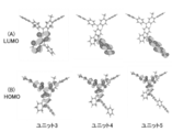
- FIG. 6 is a diagram showing an electronic state of electronic polymerization units 3 to 5 in the example (halftone image).
- the polymer of the embodiment according to the first aspect is a polymer having a structure represented by the following formula (1).
- this polymer is also referred to as polymer 1.
- G represents an aromatic hydrocarbon group which may have a substituent, an aromatic heterocyclic group which may have a substituent, or a C atom, an N atom, a B atom or a P atom
- Ar 2 to Ar 4 each independently have a divalent aromatic hydrocarbon group which may have a substituent, an aromatic heterocyclic group which may have a substituent, or a substituent.
- An aromatic hydrocarbon group which may have an aromatic heterocyclic group which may have a substituent represents a divalent group in which a plurality of groups are linked directly or via a linking group
- Ar 5 is an aromatic hydrocarbon group which may have a substituent, an aromatic heterocyclic group which may have a substituent, or an aromatic hydrocarbon group which may have a substituent or an aromatic group.
- Ar 6 represents a hydrogen atom or a substituent.
- "-*" in Ar 1 is a site (bonding position) to be bonded to G in the formula (1).
- G is an aromatic hydrocarbon group which may have a substituent, an aromatic heterocyclic group which may have a substituent, or a C atom, Represents an N atom, a B atom or a P atom.
- G has a benzene ring which may have a substituent and a substituent, from the viewpoint of excellent charge transportability and the fact that LUMO distributed in the 9-position of the carbazole ring and HOMO distributed in the main chain are localized.
- a triazine ring which may have, a fluorene ring which may have a substituent, a spirofluorene ring which may have a substituent, and a carbazole ring which may have a substituent are preferable, and the following scheme
- the structure shown in 1 is more preferable.
- the following structure may have a substituent.
- “ ⁇ *” represents a bonding position with Ar 3 .
- substituent group Z an aralkyl group having 7 to 40 carbon atoms, or a heterocyclic aralkyl group having 4 to 37 carbon atoms, or a combination thereof. Is preferred.
- the viewpoint of charge transportability it is preferably the same or different each time it appears, and is preferably an aromatic hydrocarbon group having 6 to 24 carbon atoms or an aromatic heterocyclic group having 3 to 24 carbon atoms. More preferably, it is a group, a naphthyl group, a fluorenyl group, a carbazolyl group, an indolocarbazolyl group, an indenocarbazolyl group, or an indenofluorenyl group.
- G is preferably an N atom (nitrogen atom) from the viewpoint of excellent charge transportability.
- Ar 2 to Ar 4 each independently have a divalent aromatic hydrocarbon group which may have a substituent or a substituent.
- a divalent aromatic heterocyclic group which may be substituted, or an aromatic hydrocarbon group which may have a substituent or an aromatic heterocyclic group which may have a plurality of substituents are directly or through a linking group. Represents a divalent group in which they are linked together.
- the aromatic hydrocarbon group preferably has 6 or more and 60 or less carbon atoms, and specific examples thereof include benzene ring, naphthalene ring, anthracene ring, phenanthrene ring, perylene ring, tetracene ring, pyrene ring, benzpyrene ring and chrysene ring.
- a divalent group having 2 to 10 linkages is mentioned, and a divalent group having 2 to 5 linkages is preferable.
- the aromatic heterocyclic group preferably has 3 or more and 60 or less carbon atoms, specifically, a furan ring, a benzofuran ring, a thiophene ring, a benzothiophene ring, a pyrrole ring, a pyrazole ring, an imidazole ring, an oxadiazole ring.
- the divalent group in which a plurality of aromatic hydrocarbon groups which may have a substituent or aromatic heterocyclic groups which may have a substituent are linked directly or via a linking group
- the same group can be used. May be a group in which a plurality of groups are linked, or a group in which a plurality of different groups are linked.
- a divalent group having 2 to 10 linkages is mentioned, and a divalent group having 2 to 5 linkages is preferable.
- Ar 2 is a divalent aromatic hydrocarbon group which may have a substituent and a divalent aromatic heterocyclic group which may have a substituent, from the viewpoint of excellent charge transportability and excellent durability.
- a divalent group in which one or more groups selected from ring groups are bonded directly or via a linking group is preferable, and the linking group is preferably an oxygen atom or a carbonyl group.
- an aromatic hydrocarbon group which may have a substituent is preferable, and a phenylene group which may have a substituent or a substituent
- a divalent fluorene group which may have a group is more preferable, and a phenylene group which may have a substituent is particularly preferable.
- a fluorene ring or a carbazole ring is preferably bonded to the phenylene ring directly bonded to the nitrogen atom, and one or more phenylene groups are further provided between the phenylene ring directly bonded to the nitrogen atom and the fluorene ring or carbazole ring. Structures in which are linked are also preferred. Further, a structure in which phenylene rings are linked by an oxygen atom or a carbonyl group is also preferable.
- the substituent that Ar 2 may have is the same as the substituent that G 2 may have when it is an aromatic hydrocarbon group or an aromatic heterocyclic group.
- Ar 3 has 1 to 6 divalent aromatic hydrocarbon groups which may have a substituent, from the viewpoint of being localized with LUMO distributed in the 9-position of the carbazole ring and HOMO distributed in the main chain.
- a group in which two or four divalent aromatic hydrocarbon groups which may have a substituent are linked is more preferable, and a phenylene ring which may have a substituent is one to one.
- a group in which four are linked is more preferable, and a biphenylene in which two phenylene rings which may have a substituent are linked is particularly preferable.
- the substituent which Ar 3 may have is the same as the above-mentioned substituent of Ar 2 .
- Ar 4 is preferably a group in which one or more divalent aromatic hydrocarbon groups, which may be the same or different, are linked from the viewpoint of excellent charge transportability and excellent durability.
- the group hydrocarbon group may have a substituent.
- the number of linkages is large, but from the viewpoints of charge transportability and film stability, the number of linkages is preferably small. preferable.
- Preferred aromatic hydrocarbon structures are a benzene ring, a naphthalene ring, an anthracene ring and a fluorene ring, more preferably a benzene ring and a fluorene ring.
- the group in which a plurality of phenylene rings may be substituted may be a group in which 1 to 4 phenylene rings that may have a substituent are linked, or a phenylene ring that may have a substituent and a substituent.
- a group in which a fluorene ring is linked is preferable. From the viewpoint of widening LUMO, biphenylene in which two phenylene rings which may have a substituent are linked is particularly preferable.
- any one of the substituent groups Z described later or a combination thereof can be used. From the viewpoint of inhibiting the spread of LUMO, it is preferably other than N-carbazolyl group, indolocarbazolyl group, and indenocarbazolyl group, and more preferable substituents are phenyl group, naphthyl group, and fluorenyl group. is there. Further, it is also preferable not to have a substituent.
- Ar 5 is an aromatic hydrocarbon group which may have a substituent, an aromatic heterocyclic group which may have a substituent, or an aromatic hydrocarbon group which may have a substituent, and
- the group selected from the aromatic heterocyclic groups which may have a substituent is a monovalent group in which a plurality of groups are linked directly or via a linking group.
- a divalent group having 2 to 10 linkages is mentioned, and a divalent group having 2 to 5 linkages is preferable.
- the aromatic hydrocarbons and aromatic heterocycles the aromatic hydrocarbon structures and aromatic heterocycle structures described above for Ar2 to Ar4, which are monovalent structures, can be used.
- a structure represented by any one of the following schemes 2 at the 9-position of the carbazole ring specified in Ar 1 of the formula (1). Further, it is selected from a-1 to a-4, b-1 to b-9, c-1 to c-5, d-1 to d-16, and e1 to e4 from the viewpoint of distributing the LUMO of the molecule. Preferred structure. Further, from the viewpoint of promoting the spread of LUMO of the molecule by having an electron-withdrawing group, a-1 to a-4, b-1 to b-9, d-1 to d-13, and e1 to e4. Structures selected from are preferred.
- a structure selected from a-1 to a-4, d-1 to d-13, and e1 to e4 is preferable from the viewpoint of the effect of confining excitons formed in the light emitting layer, which has a higher triplet level. .. It is also preferably a phenyl group. Further, these structures may have a substituent.
- “ ⁇ *” represents the bonding position with Ar 4, and when there are a plurality of “ ⁇ *”, one of them represents the bonding position with Ar 4 .
- any one of the substituent groups Z described later or a combination thereof can be used. From the viewpoint of durability and charge transportability, it is preferable to be selected from the same substituents that Ar 4 may have.
- Ar 6 represents a hydrogen atom or a substituent.
- Ar 6 is a substituent, it is not particularly limited, but is preferably an aromatic hydrocarbon group which may have a substituent or an aromatic heterocyclic group which may have a substituent.
- a preferable structure is a monovalent structure similar to the aromatic hydrocarbon structure and the aromatic heterocyclic structure described in Ar 2 to Ar 4 .
- Ar 6 is preferably bonded to the 3-position of carbazole from the viewpoint of improving durability.
- Ar 6 is preferably a hydrogen atom from the viewpoint of ease of synthesis and charge transportability.
- Ar 6 is preferably an aromatic hydrocarbon group which may have a substituent or an aromatic heterocyclic group which may have a substituent, from the viewpoint of improving durability and charge transporting property. More preferably, it is an aromatic hydrocarbon group which may have a substituent.
- Substituents when Ar 6 is an aromatic hydrocarbon group which may have a substituent or an aromatic heterocyclic group which may have a substituent are included in the substituent group Z described later. It is the same as the substituent or the crosslinkable group described later, the preferred substituents are also the same, and the substituents which these substituents may further have are also the same. Further, from the viewpoint of insolubilization, it is preferable that at least one crosslinkable group described below is contained as a substituent.
- the formula (1) is more preferably a repeating unit represented by any of the following formulas (2)-1 to (2)-3.
- Ar 1 is the same as Ar 1 of formula (1), X represents -C(R 5 )(R 6 )-, -N(R 7 )- or -C(R 11 )(R 12 )-C(R 13 )(R 14 )-, R 1 to R 4 each independently represent an alkyl group which may have a substituent, an alkoxy group which may have a substituent, or an aralkyl group which may have a substituent, R 5 to R 7 and R 11 to R 14 are each independently an alkyl group which may have a substituent, an alkoxy group which may have a substituent, or a substituent which may have a substituent.
- An aralkyl group or represents an aromatic hydrocarbon group which may have a substituent
- a and b are each independently an integer of 0 to 4
- c1 and c2 are each independently an integer of 1 to 3
- d1 and d2 are each independently an integer of 0 to 4
- R 1 , R 2 , R 3 and R 4 may be the same or different.
- (X) X is either -C(R 5 )(R 6 )-, -N(R 7 )- or -C(R 11 )(R 12 )-C(R 13 )(R 14 )-. From the viewpoint of durability, -C(R 5 )(R 6 )- and -N(R 7 )- are preferable.
- R 1 and R 2 in the repeating units represented by the above formulas (2)-1 to (2)-3 are each independently linear, branched or cyclic alkyl which may have a substituent. It is preferably a group.
- the number of carbon atoms of the alkyl group is not particularly limited, but in order to maintain the solubility of the polymer, the number of carbon atoms is preferably 1 or more and 6 or less, more preferably 3 or less, and further preferably a methyl group or an ethyl group. ..
- R 1 and R 2 may be the same or different, but the charge can be uniformly distributed around the nitrogen atom, Further, since it is easy to synthesize, it is preferable that all R 1 and R 2 are the same group.
- R 3 and R 4 in the repeating units represented by the above formulas (2)-1 to (2)-3 are each independently linear, branched or cyclic alkyl which may have a substituent. It is preferably a group.
- the number of carbon atoms of the alkyl group is not particularly limited, but in order to maintain the solubility of the polymer, the number of carbon atoms is preferably 1 or more, more preferably 4 or more, preferably 12 or less, and further preferably 8 It is below, and it is especially preferable that it is a hexyl group.
- R 5 to R 7 and R 11 to R 14 are each independently an alkyl group which may have a substituent, an alkoxy group which may have a substituent, or a substituent which may have a substituent. It is preferably an aralkyl group or an aromatic hydrocarbon group which may have a substituent.
- the alkyl group is not particularly limited, but a longer one is preferable in order to improve the solubility of the polymer, and a shorter one is preferable in order to improve the stability of the film and the charge transport property.
- the carbon number is preferably 1 or more and 24 or less, more preferably 12 or less, further preferably 8 or less, particularly preferably 6 or less, more preferably 2 or more, further preferably 3 or more, particularly preferably 4 or more. It may also have a linear, branched or cyclic structure.
- the alkoxy group is not particularly limited, but since it tends to improve the solubility of the polymer, it preferably has 1 or more and 24 or less carbon atoms, more preferably 12 or less, more preferably 8 or less, particularly preferably 6 or less, 2 or more is more preferable, 3 or more is further preferable, and 4 or more is particularly preferable. Specific examples thereof include methoxy group, ethoxy group, n-propoxy group, i-propoxy group, n-butoxy group, i-butoxy group, tert-butoxy group and hexyloxy group.
- the aralkyl group is not particularly limited, but since it tends to improve the solubility of the polymer, it preferably has 5 or more and 60 or less carbon atoms, more preferably 40 or less, more preferably 7 or more, still more preferably 10 or more, Particularly preferred is 12 or more.
- 1,1-dimethyl-1-phenylmethyl group 1,1-di(n-butyl)-1-phenylmethyl group, 1,1-di(n-hexyl)-1-phenylmethyl group , 1,1-di(n-octyl)-1-phenylmethyl group, phenylmethyl group, phenylethyl group, 3-phenyl-1-propyl group, 4-phenyl-1-n-butyl group, 1-methyl- 1-phenylethyl group, 5-phenyl-1-n-propyl group, 6-phenyl-1-n-hexyl group, 6-naphthyl-1-n-hexyl group, 7-phenyl-1-n-heptyl group, Examples include 8-phenyl-1-n-octyl group and 4-phenylcyclohexyl group.
- the aromatic hydrocarbon group is not particularly limited, but since it tends to improve the solubility of the polymer, it preferably has 6 or more and 60 or less carbon atoms, more preferably 30 or less, and still more preferably 24 or less, 14 The following are particularly preferred.
- a 6-membered ring such as a benzene ring, a naphthalene ring, an anthracene ring, a phenanthrene ring, a perylene ring, a tetracene ring, a pyrene ring, a benzpyrene ring, a chrysene ring, a triphenylene ring, an acenaphthene ring, a fluoranthene ring, or a fluorene ring.
- Examples thereof include a monocyclic group or a monovalent group of 2 to 5 condensed rings, or a group in which a ring structure selected from these is linked in 2 to 8, and a monocyclic group or a group in which 2 to 4 or less are linked is preferable.
- R 5 to R 7 are preferably alkyl groups or aromatic hydrocarbon groups, R 5 and R 6 are more preferably alkyl groups, and R 7 is aromatic hydrocarbon.
- a group is more preferable, and the preferable carbon number is as described above.
- R 5 and R 6 are preferably an alkyl group having 3 or more and 8 or less carbon atoms or an aralkyl group having 9 or more and 40 or less carbon atoms from the viewpoint of improving solubility and excellent charge transportability.
- the alkyl group of R 1 to R 4 , the alkyl group, alkoxy group, aralkyl group and aromatic hydrocarbon group of R 5 to R 7 and R 11 to R 14 may have a substituent.
- the substituent which may be possessed is the group mentioned as the preferable group of the alkyl group, alkoxy group, aralkyl group and aromatic hydrocarbon group of R 5 to R 7 and R 11 to R 14 , or the crosslinkable group which will be described later. Groups.
- the alkyl group represented by R 1 to R 4, the alkyl group represented by R 5 to R 7 and the alkyl group represented by R 11 to R 14 , an aralkyl group and an aromatic hydrocarbon group have a substituent from the viewpoint of lowering the voltage. Most preferably not.
- the substituent which R 5 to R 7 and R 11 to R 14 may have is a solvent when the polymer of this embodiment is formed into a film and then another layer is formed by coating.
- a crosslinkable group described later is preferable.
- a and b are each independently an integer of 0 to 4. Further, a+b is preferably 1 or more. Further, each of a and b is preferably 2 or less, and more preferably both a and b are 1.
- c1 and c2 are each independently an integer of 1 to 3, and d1 and d2 are independently 0 to 4 Is an integer.
- Each of c1, c2, d1 and d2 is preferably 2 or less, more preferably equal to c1, c2, d1 and d2, and all of c1, c2, d1 and d2 are 1 or 2. Is more preferable, and it is particularly preferable that all of c1, c2, d1 and d2 are 1.
- substituent group Z examples include the following structures. For example, methyl group, ethyl group, n-propyl group, i-propyl group, n-butyl group, i-butyl group, sec-butyl group, tert-butyl group, n-hexyl group, cyclohexyl group, dodecyl group, etc.
- substituent group Z the above-mentioned alkyl group, alkoxy group, aromatic hydrocarbon group and aromatic heterocyclic group are preferable. From the viewpoint of charge transportability, it is more preferable that the compound does not have a substituent.
- each substituent of the above substituent group Z may further have a substituent.
- substituents include the same ones as the above-mentioned substituents (substituent group Z) or the crosslinkable groups described later.
- it is an alkyl group having 6 or less carbon atoms, an alkoxy group having 6 or less carbon atoms, a phenyl group, or a crosslinkable group described later, which has no further substituent. From the viewpoint of charge transportability, it is more preferable not to have an additional substituent.
- the terminal group refers to the structure of the terminal portion of the polymer, which is formed by the end cap agent used at the end of polymerization of the polymer.
- the terminal group of the polymer of this embodiment is usually a hydrocarbon group. From the viewpoint of charge transportability, the hydrocarbon group preferably has 1 or more and 60 or less carbon atoms, more preferably 1 or more and 40 or less, and still more preferably 1 or more and 30 or less.
- hydrocarbon groups may further have a substituent, and the substituent which may further have is preferably an alkyl group or an aromatic hydrocarbon group, and there are plural substituents which may further have these. In this case, they may be bonded to each other to form a ring. From the viewpoint of charge transportability and durability, an alkyl group or an aromatic hydrocarbon group is preferable, and an aromatic hydrocarbon group is more preferable.
- the polymer of the present embodiment preferably has a soluble group in order to exhibit solubility in a solvent.
- the soluble group in the present embodiment is a group having a linear or branched alkyl group or alkylene group having 3 to 24 carbon atoms, preferably 12 carbon atoms or less.
- an alkyl group, an alkoxy group, or an aralkyl group is preferable, and examples thereof include an n-propyl group, a 2-propyl group, an n-butyl group, and an isobutyl group. More preferably, it is an n-hexyl group or an n-octyl group.
- the soluble group may have a substituent. When one or more of R 1 to R 7 and R 11 to R 14 have these structures, those groups are considered to be soluble groups. Further, when the substituents in the present embodiment satisfy the condition of the soluble group, those substituents are regarded as soluble groups.
- the polymer of the present embodiment has a large amount of soluble groups from the viewpoint of easily obtaining a polymer solution that can be used in the wet film formation method.
- the thinner the thickness is the less the thickness is reduced by dissolving the layer in the solvent when another layer is formed by the wet film formation method on the formed layer.
- the number of soluble groups contained in the polymer of the present embodiment can be represented by the number of moles per 1 g of the polymer.
- the number of soluble groups possessed by the polymer of the present embodiment is represented by the number of moles per 1 g of the polymer, it is usually 4.0 mmol or less, preferably 3.0 mmol or less, and more preferably 1 mmol per 1 g of the polymer. It is 2.0 mmol or less, and usually 0.1 mmol or more, preferably 0.5 mmol or more.
- the number of soluble groups is within the above range, the polymer is easily dissolved in the solvent, and a composition containing the polymer suitable for the wet film formation method is easily obtained. Further, since the density of the soluble group is moderate, the solubility in the organic solvent after drying with the heating solvent is sufficient, so that the multilayer laminated structure can be formed by the wet film forming method.
- the number of soluble groups per 1 g of the polymer can be calculated from the molar ratio of the charged monomers at the time of synthesis, excluding the terminal group from the polymer, and the structural formula.
- the molecular weight of the repeating unit excluding the terminal group in the polymer 1 is 767 on average, and the hexyl group which is a soluble group is The average is 2 per repeating unit.
- the number of soluble groups per 1 g of molecular weight is calculated to be 2.09 mmol.
- the polymer of the present embodiment may have a crosslinkable group as a substituent.
- the crosslinkable group in the polymer of the present embodiment may be present in the repeating unit represented by the formula (1), or may be present in a repeating unit different from the repeating unit represented by the formula (1). You may have.
- the side chain Ar 1 has a crosslinkable group because the crosslink reaction easily proceeds. By having a crosslinkable group, it is possible to cause a large difference in solubility in an organic solvent before and after a reaction (hardly soluble reaction) that occurs due to heat and/or irradiation with an active energy ray.
- the crosslinkable group is a group which reacts with a group constituting another molecule located in the vicinity of the crosslinkable group by irradiation of heat and/or an active energy ray to form a new chemical bond.
- the reactive group may be the same as or different from the crosslinkable group.
- the crosslinkable group is preferably a group containing a cyclobutene ring condensed to an aromatic ring or an alkenyl group bonded to the aromatic ring, and more preferably a group selected from the following crosslinkable group group T.
- the crosslinkable group is preferably further substituted with the substituent contained in each structure.
- Crosslinkable group T The crosslinkable group group T has the structure shown below.
- R 21 to R 23 each independently represent a hydrogen atom or an alkyl group.
- R 24 to R 26 each independently represent an alkyl group or an alkoxy group.
- p represents an integer of 1 to 4
- q represents an integer of 1 to 5
- r represents an integer of 1 to 7.
- p 2 or more
- a plurality of R 24 s may be the same or different, and adjacent R 24 s may combine with each other to form a ring.
- plural R 25 s may be the same or different, and adjacent R 25 s may be bonded to each other to form a ring.
- r is 2 or more, a plurality of R 26's may be the same or different.
- Ar 21 and Ar 22 represent an aromatic hydrocarbon group or an aromatic heterocyclic group which may have a substituent.
- Examples of the alkyl group of R 21 to R 26 include a linear or branched chain alkyl group having 6 or less carbon atoms. Examples thereof include a methyl group, an ethyl group, an n-propyl group, a 2-propyl group, an n-butyl group and an isobutyl group. More preferably, it is a methyl group or an ethyl group.
- the carbon number of R 21 to R 26 is 6 or less, the cross-linking reaction is not sterically hindered and insolubilization of the film tends to occur.
- alkoxy group of R 24 to R 26 examples include a linear or branched chain alkoxy group having 6 or less carbon atoms, for example, a methoxy group, an ethoxy group, an n-propoxy group, a 2-propoxy group, An n-butoxy group and the like. More preferably, it is a methoxy group or an ethoxy group.
- the carbon number of R 24 to R 26 is 6 or less, the crosslinking reaction is not sterically hindered, and insolubilization of the film tends to occur.
- the aromatic hydrocarbon group which may have a substituent of Ar 21 and Ar 22 is, for example, a 6-membered monocyclic ring having one free valence, such as a benzene ring or a naphthalene ring, or 2 to 5 condensed rings can be mentioned. Particularly preferred is a benzene ring having one free valence.
- Ar 22 may be a group in which two or more aromatic hydrocarbon groups that may have a substituent are bonded. Examples of such a group include a biphenylene group and a terphenylene group, and a 4,4′-biphenylene group is preferable.
- the substituents that Ar 21 and Ar 22 may have are the same as those in the above-mentioned substituent group Z.
- a group that undergoes an addition reaction is preferable because it further improves the electrochemical stability of the device.
- a cyclobutene ring condensed to an aromatic ring having a monovalent free valence and a 1,2-dihydro having a monovalent free valence are preferable because the structure after the crosslinking is particularly stable.
- a group containing a cyclobuta[a]naphthalene ring is preferable, and a benzocyclobutene ring or a 1,2-dihydrocyclobuta[a]naphthalene ring having a monovalent free valence is more preferable, and the crosslinking reaction temperature is low.
- a 1,2-dihydrocyclobuta[a]naphthalene ring having a monovalent free valence is particularly preferred.
- the crosslinkable group contained in the polymer of the present embodiment is preferably insoluble because it becomes sufficiently insoluble by crosslinking and it becomes easy to form another layer thereon by a wet film forming method.
- the number of crosslinkable groups is small in that the formed layer is less likely to be cracked, unreacted crosslinkable groups are less likely to remain, and the organic electroluminescent element is likely to have a long life.
- the number of crosslinkable groups present in one polymer chain is preferably 1 or more, more preferably 2 or more, and preferably 200 or less, more preferably 100 or less.
- the number of crosslinkable groups that the polymer of the present embodiment has can be represented by the number per 1000 molecular weight of the polymer.
- the number of crosslinkable groups possessed by the polymer of the present embodiment is represented by the number per 1000 of the molecular weight of the polymer, it is usually 3.0 or less, preferably 2.0 or less, more preferably 1000 per 1000 of the molecular weight. It is 1.0 or less, and usually 0.01 or more, preferably 0.05 or more.
- the number of crosslinkable groups is within the above range, cracks are less likely to occur, and a flat film is easily obtained. Further, since the crosslink density is appropriate, there are few unreacted crosslinkable groups remaining in the layer after the crosslinking reaction, and it is difficult to affect the life of the obtained device. Further, since the poor solubility in the organic solvent after the crosslinking reaction is sufficient, it is easy to form a multilayer laminated structure by a wet film forming method.
- the number of crosslinkable groups per 1000 molecular weight of the polymer can be calculated from the molar ratio of the charged monomers at the time of synthesis and the structural formula, excluding the terminal group from the polymer.
- the molecular weight of the repeating unit excluding the terminal group is 816 on average, and the crosslinkable group is 0. It is 138.
- the number of crosslinkable groups per 1,000 molecular weight is calculated to be 0.15.
- the content of the repeating unit represented by the formula (1) is not particularly limited, but usually 50 mol% or more and preferably 60 mol% or more are contained in the polymer, 70 It is more preferably contained in an amount of mol% or more, particularly preferably in an amount of 80 mol% or more.
- the repeating unit may be composed of only the repeating unit represented by the formula (1), but for the purpose of balancing various performances when the organic electroluminescent device is used, the formula ( It may have a repeating unit other than 1), in which case the content of the repeating unit represented by the formula (1) in the polymer is usually 95 mol% or more, preferably 99 mol% That is all.
- the polymer of the present embodiment preferably further contains a repeating unit represented by any of the following (3)-1 to formula (3)-3.
- Ar 7 has, independently of each repeating unit, an aromatic hydrocarbon group which may have a substituent, an aromatic heterocyclic group which may have a substituent, or a substituent which may have a substituent.
- a good aromatic hydrocarbon group or an aromatic heterocyclic group which may have a substituent represents a divalent group in which a plurality of groups are linked directly or via a linking group
- X represents -C(R 5 )(R 6 )-, -N(R 7 )- or -C(R 11 )(R 12 )-C(R 13 )(R 14 )-
- R 1 to R 4 each independently represent an alkyl group which may have a substituent, an alkoxy group which may have a substituent, or an aralkyl group which may have a substituent
- R 5 to R 7 and R 11 to R 14 are each independently an alkyl group which may have a substituent, an alkoxy group which may have a substituent, or a substituent which
- An aralkyl group or represents an aromatic hydrocarbon group which may have a substituent
- a and b are each independently an integer of 0 to 4
- c1 and c2 are each independently an integer of 1 to 3
- d1 and d2 are each independently an integer of 0 to 4
- R 1 , R 2 , R 3 and R 4 may be the same or different.
- Ar 7 is independently an aromatic hydrocarbon group which may have a substituent or a substituent in each repeating unit. Represents an aromatic heterocyclic group which may have a group.
- the aromatic hydrocarbon group preferably has 6 or more and 60 or less carbon atoms, and specific examples thereof include benzene ring, naphthalene ring, anthracene ring, phenanthrene ring, perylene ring, tetracene ring, pyrene ring, benzpyrene ring and chrysene ring.
- a divalent group having 2 to 10 linkages is mentioned, and a divalent group having 2 to 5 linkages is preferable.
- the aromatic heterocyclic group preferably has 3 or more and 60 or less carbon atoms, specifically, a furan ring, a benzofuran ring, a thiophene ring, a benzothiophene ring, a pyrrole ring, a pyrazole ring, an imidazole ring, an oxadiazole ring.
- Ar 7 is preferably an aromatic hydrocarbon group which may have a substituent, from the viewpoints of excellent charge transportability and excellent durability, and among them, a benzene ring or a fluorene ring which may have a substituent.
- a monovalent group that is, a phenyl group which may have a substituent or a fluorenyl group is more preferable, a fluorenyl group which may have a substituent is more preferable, and a substituent may be given.
- the 2-fluorenyl group is particularly preferred.
- the substituent that the aromatic hydrocarbon group or aromatic heterocyclic group of Ar 7 may have is not particularly limited as long as it does not significantly reduce the properties of the polymer of the present embodiment.
- a group selected from the substituent group Z or the crosslinkable group is exemplified, and an alkyl group, an alkoxy group, an aromatic hydrocarbon group, an aromatic heterocyclic group or the crosslinkable group is preferable, and an alkyl group is more preferable. preferable.
- Ar 7 is preferably a fluorenyl group substituted with an alkyl group having 1 to 24 carbon atoms, and particularly preferably a 2-fluorenyl group substituted with an alkyl group having 4 to 12 carbon atoms. preferable. Furthermore, a 9-alkyl-2-fluorenyl group in which an alkyl group is substituted at the 9-position of a 2-fluorenyl group is preferable, and a 9,9-dialkyl-2-fluorenyl group in which an alkyl group is 2-substituted is particularly preferable.
- the solubility in a solvent and the durability of the fluorene ring tend to be improved. Furthermore, since both the 9-position and the 9'-position are fluorenyl groups substituted with an alkyl group, the solubility in a solvent and the durability of the fluorene ring tend to be further improved. Further, it is preferable that Ar 7 contains the above-mentioned crosslinkable group, since insolubility in a solvent is improved when the film is formed and laminated and applied.
- the polymer preferably contains a repeating unit represented by Formula (3)-1 to Formula (3)-3, which contains at least one crosslinkable group described above as a further substituent, It is preferable that the crosslinkable group is further substituted with a substituent which the aromatic hydrocarbon group represented by Ar 7 or the aromatic heterocyclic group may have. From the viewpoint of durability or low voltage of the element when used in an organic electroluminescent element, it is preferable to include a repeating unit represented by the formula (3)-1 or the formula (3)-2.
- the weight average molecular weight (Mw) of the polymer of the present embodiment is usually 3,000,000 or less, preferably 1,000,000 or less, more preferably 500,000 or less, further preferably 200,000 or less, particularly preferably Is 100,000 or less. It is usually 10,000 or more, preferably 20,000 or more, more preferably 30,000 or more.
- the weight average molecular weight of the polymer When the weight average molecular weight of the polymer is equal to or less than the above upper limit, solubility in a solvent is obtained and film forming property tends to be excellent. Further, when the weight average molecular weight of the polymer is at least the above lower limit, the decrease in the glass transition temperature, melting point and vaporization temperature of the polymer may be suppressed, and the heat resistance may be improved. In addition, the insolubility of the coating film after the crosslinking reaction in the organic solvent may be sufficient.
- the number average molecular weight (Mn) of the polymer of the present embodiment is usually 2,500,000 or less, preferably 750,000 or less, more preferably 400,000 or less, and particularly preferably 100,000 or less. Further, it is usually 2,000 or more, preferably 4,000 or more, more preferably 8,000 or more, and further preferably 20,000 or more.
- the dispersity (Mw/Mn) in the polymer of the present embodiment is preferably 3.5 or less, more preferably 2.5 or less, and particularly preferably 2.0 or less.
- the dispersity of the polymer is not more than the above upper limit, purification is easy, and solubility in a solvent and charge transporting ability are good.
- the weight average molecular weight and number average molecular weight of a polymer are determined by SEC (size exclusion chromatography) measurement.
- SEC size exclusion chromatography
- using the calibration curve calculated from the elution time of polystyrene (standard sample) of known molecular weight By converting, the weight average molecular weight and the number average molecular weight are calculated.
- the polymer of the present embodiment may further contain a repeating unit represented by the formula (4) or the formula (5) from the viewpoint of charge transportability and durability.
- the repeating unit represented by the following formula (4) is a repeating unit represented by the above formula (1), formula (2)-1 to formula (2)-3 and formula (3)-1 to formula (3)-3. It is a structure of a repeating unit which may be a part of the structural unit in the unit but is different from them.
- Ar 8 represents an aromatic hydrocarbon group which may have a substituent or an aromatic heterocyclic group which may have a substituent
- Ar 9 may have a divalent aromatic hydrocarbon group which may have a substituent, a divalent aromatic heterocyclic group which may have a substituent, or may have the substituent. It represents a divalent group in which a plurality of groups selected from a good aromatic hydrocarbon group and an aromatic heterocyclic group which may have the substituent are linked directly or via a linking group.
- Ar 10 may have a divalent aromatic hydrocarbon group which may have a substituent, a divalent aromatic heterocyclic group which may have a substituent, or may have the substituent. It represents a divalent group in which a plurality of groups selected from an aromatic hydrocarbon group and an aromatic heterocyclic group which may have the substituent are linked directly or via a linking group.
- Ar 8 is an aromatic hydrocarbon group or an aromatic heterocyclic group which Ar 6 of the formula (1) can take.
- Ar 9 and Ar 10 are groups selected from the same group, and Ar 9 and Ar 10 are groups selected from the same groups as the aromatic hydrocarbon group and the aromatic heterocyclic group that can be taken by the formula (1) Ar 2.
- the substituent which may be present is preferably the same as the above-mentioned Substituent Group Z or the above-mentioned crosslinkable group.
- the polymer of this embodiment is most preferably a repeating unit represented by any of the following formulas (6).
- Ar T represents the above Ar 1 or the above Ar 7, and a plurality of Ar T in each polymer may be the same or different, and at least one of the Ar T in each polymer is the above Ar 1 .
- Represents X, R 1 , R 2 , R 3 and R 4 are the same as those in the above formulas (2)-1 to (2)-3.
- n and m represent the number of repetitions.
- the polymer according to another embodiment of the first aspect of the present invention is a polymer having a structure represented by the following formula (12) or the following formula (13).
- G, Ar 2 , Ar 4 and Ar 6 are respectively the same as G, Ar 2 and Ar 4 in formula (1), Ar 55 is selected from a-1 to a-4, b-1 to b-9, c-1 to c-5, d-1 to d-16, and e1 to e4 shown in Scheme 2 below. Represents either structure.
- "-*" in Ar 12 is a site (bonding position) to be bonded to G in the formula (12).
- the preferable range of Ar 55 is the same as the preferable range of Ar 5 in the above formula (1), and the substituent which it may have is the same as Ar 5 in the above formula (1). Is.
- G, Ar 2 , Ar 4 and Ar 6 are respectively the same as G, Ar 2 and Ar 4 in the above formula (1), Ar 33 and Ar 34 each independently have a divalent aromatic hydrocarbon group which may have a substituent, an aromatic heterocyclic group which may have a substituent, or a substituent.
- An aromatic hydrocarbon group which may have an aromatic heterocyclic group which may have a substituent represents a divalent group in which a plurality of groups are linked directly or via a linking group
- Ar 555 is a hydrogen atom, an aromatic hydrocarbon group which may have a substituent, an aromatic heterocyclic group which may have a substituent, or an aromatic hydrocarbon which may have a substituent. It represents a monovalent group in which a plurality of hydrogen groups or aromatic heterocyclic groups are linked directly or via a linking group.
- "-*" in Ar 13 is a site (bonding position) to be bonded to G in the formula (13).
- the preferred ranges of Ar 33 and Ar 34 , and the substituents that they may have are the same as those of Ar 2 and Ar 4 in the above formula (1), and a plurality of them are connected.
- the preferable range in this case is also the same.
- the preferred range of Ar 555 is the same as the preferred range of Ar 5 in the above formula (1).
- the substituent which it may have is the same as Ar 5 in the formula (1).
- polymers of this embodiment are shown below, but the polymer is not limited to these.
- the numbers in the chemical formulas represent the molar ratio of repeating units.
- These polymers may be random copolymers, alternating copolymers, block copolymers, graft copolymers, or the like, and the order of arranging the monomers is not limited.
- the method for producing the polymer of this embodiment is not particularly limited.
- it can be produced by a polymerization method by Suzuki reaction, a polymerization method by Grignard reaction, a polymerization method by Yamamoto reaction, a polymerization method by Ullmann reaction, a polymerization method by Buchwald-Hartwig reaction, and the like.
- the dihalogenated aryl represented by the formula (1a) (Y represents a halogen atom such as I, Br, Cl, F) and the formula (1).
- the polymer of this embodiment is synthesized by reacting with the primary aminoaryl represented by 1b) and further reacting with 2a.
- Ar 1 , R 1 to R 2 , X, a, and b have the same meanings as in formulas (2)-1 to (2)-3, respectively.
- c and d have the same meanings as c1 or c2 and d1 or d2 in the formulas (2)-1 to (2)-3, respectively.
- n and m represent the number of repetitions.
- the reaction for forming an N-aryl bond is usually carried out in the presence of a base such as potassium carbonate, sodium tert-butoxy, triethylamine or the like. It can also be carried out in the presence of a transition metal catalyst such as copper or palladium complex.
- An organic electroluminescent device is an organic electroluminescent device having an anode, a cathode, and an organic layer between the anode and the cathode, wherein the organic layer is a hole.
- the hole transport layer contains the polymer 1 represented by the formula (1) or a polymer obtained by crosslinking the polymer 1,
- a material having a partial structure represented by the following formula (CzP) in which both the polymer 1 or the polymer obtained by crosslinking the polymer 1 and at least one of the materials contained in the light emitting layer have a carbazole ring (the following formula (CzP)
- the organic electroluminescence device contains a compound having a partial structure represented by Regarding the description of “material” in the present specification, a description that can be replaced with “compound” may be replaced with “compound”.
- both the material contained in the hole transport layer and the material contained in the light emitting layer include a material having a partial structure represented by the formula (CzP), and the material contained in the hole transport layer or the One of the materials contained in the light emitting layer contains a material having two or more partial structures represented by the formula (CzP), and more preferably, the material contained in the light emitting layer is represented by the formula (CzP). It is to include a material (compound) having two or more partial structures represented by the formula (CzP), and it is particularly preferable that the material contained in the hole transport layer and the material contained in the light emitting layer are both represented by the formula (CzP). Is to include a material (compound) having two or more of.
- Such a combination is expected to be driven at a lower voltage, emit light with high efficiency, and have a long life. It is also preferable that at least one of the hole transport layer and the light emitting layer contains two or more kinds of materials having a partial structure represented by the formula (CzP), and particularly, the light emitting layer is represented by the formula (CzP). It is preferable to include two or more kinds of materials having a partial structure. Even in such a combination, driving at a lower voltage, high-efficiency light emission, and long life are expected.
- the material contained in the hole transport layer having the partial structure represented by the formula (CzP) is not particularly limited, but is preferably a polymer compound.
- the polymer compound is preferably a polymer compound having an arylamine structure.
- the arylamine polymer compound is more preferably a polymer having a repeating unit represented by the following formula (20).
- the material contained in the light emitting layer having the partial structure represented by the formula (CzP) is not particularly limited, but is preferably a low molecular weight compound.
- the number of formula (CzP) contained in the polymer compound is the number of formula (CzP) contained in the repeating unit of the polymer compound. It is preferably at least a number.
- the number of formula (CzP) contained in the polymer compound is twice the number of repeating units of the polymer compound.
- the polymer compound has a plurality of repeating units, at least one repeating unit may have the formula (CzP).
- Formula (CzP) may have a substituent.
- the coupling method between the material contained in the hole transport layer or the material contained in the light emitting layer and the formula (CzP) is not particularly limited.
- the carbazole moiety and the material contained in the hole transport layer or the material contained in the light emitting layer may be bonded, and the benzene moiety and the material contained in the hole transport layer or the material contained in the light emitting layer are combined. May be combined.
- Formula (CzP) can be used for the light emitting material used for the light emitting layer or the low molecular weight compound used as the host material, and in the case of the host material, for example,
- *1, *2 and *3 are bond positions with the skeleton of the host material, and it is sufficient that at least one of *1, *2 and *3 is bonded.
- the skeleton of the host material may be directly bonded or may be bonded via another structure.
- Formula (CzP-2) may have a substituent.
- the other structure which may be interposed is not particularly limited, but is preferably an aromatic hydrocarbon group which may have a substituent, an aromatic heterocyclic group which may have a substituent, or a substituent. Examples of the structure include a structure in which two or more groups selected from an aromatic hydrocarbon group which may have a substituent and an aromatic heterocyclic group which may have a substituent are linked to each other.
- a structure in which a plurality of two or more groups selected from an aromatic hydrocarbon group which may have a substituent and an aromatic heterocyclic group which may have a substituent can be used may be used.
- the substituents and preferable ranges are also the same.
- a group selected from the aforementioned substituent group Z can be used.
- Charge transfer between the hole-transporting layer and the light-emitting layer adjacent to the hole-transporting layer is mainly performed between the material forming the hole-transporting layer and the host material in the light-emitting layer.
- the host material used has the formula (CzP) and/or the formula (CzP-2), the hole transport property at the interface can be particularly improved.
- the skeleton of the host material is preferably selected from those having an electron transporting property, a hole transporting property, and both an electron transporting property and a hole transporting property.
- the skeleton having excellent charge transportability specifically, an aromatic structure, an aromatic amine structure, a triarylamine structure, a dibenzofuran structure, a naphthalene structure, a phenanthrene structure, a phthalocyanine structure, a porphyrin structure, a thiophene structure, a benzylphenyl structure, Examples thereof include those having a fluorene structure, a quinacridone structure, a triphenylene structure, a carbazole structure, a pyrene structure, an anthracene structure, a phenanthroline structure, a quinoline structure, a pyridine structure, a pyrimidine structure, a triazine structure, an oxadiazole structure or an imidazole structure.
- the electron-transporting material a compound having a pyridine structure, a pyrimidine structure, and a triazine structure is more preferable, and a compound having a pyrimidine structure and a triazine structure is more preferable, from the viewpoint of a material having an excellent electron-transporting property and a relatively stable structure. More preferably,
- the hole-transporting material is a compound having a structure having an excellent hole-transporting property, and the skeleton having an excellent charge-transporting property has a carbazole structure, a dibenzofuran structure, a triarylamine structure, a naphthalene structure, a phenanthrene structure or pyrene. Those having a structure can be used, and among these, those having a carbazole structure, a dibenzofuran structure or a triarylamine structure are particularly preferable.
- the host material of the light emitting layer preferably has a condensed ring structure of 3 or more rings, and more preferably a compound having 2 or more condensed ring structures of 3 or more rings or a compound having at least one condensed ring of 5 or more rings. preferable.
- the rigidity of the molecule is increased, and the effect of suppressing the degree of molecular motion in response to heat is easily obtained.
- the condensed ring having 3 or more rings and the condensed ring having 5 or more rings preferably have an aromatic hydrocarbon ring or an aromatic heterocycle from the viewpoints of charge transportability and material durability.
- condensed ring structure having 3 or more rings examples include anthracene structure, phenanthrene structure, pyrene structure, chrysene structure, naphthacene structure, triphenylene structure, fluorene structure, benzofluorene structure, indenofluorene structure, indolofluorene structure, Examples thereof include a carbazole structure, an indenocarbazole structure, an indolocarbazole structure, a dibenzofuran structure and a dibenzothiophene structure.
- a carbazole structure or an indolocarbazole structure is more preferable from the viewpoint of durability against electric charges.
- At least one of the host materials of the light emitting layer is preferably a material having a pyrimidine skeleton or a triazine skeleton.
- a material having a pyrimidine skeleton or a triazine skeleton As the structure used between the skeleton of the host material and the formula (CzP-2), for example, an arylene group can be used. Examples of the arylene group include phenylene, biphenylene and triphenylene, which may have a branch.
- the host material of the light emitting layer is preferably a polymer material from the viewpoint of excellent flexibility.
- a light emitting layer formed using a material having excellent flexibility is preferable as a light emitting layer of an organic electroluminescent device formed on a flexible substrate.
- the molecular weight is preferably 5,000 or more and 1,000,000 or less, more preferably 10,000 or more and 500,000 or less, and more preferably 10,000. The above is 100,000 or less.
- the compound having a partial structure represented by the formula (CzP), particularly the low molecular weight compound, contained in the light emitting layer is represented by any one of the following formula (14), the following formula (15), or the following formula (16). It is preferable that it is a compound.
- A is a partial structure represented by the above formula (CzP) and may have a substituent.
- B represents a single bond or an arbitrary partial structure. When there are a plurality of A's, they may be the same or different from each other. When there are a plurality of Bs, they may be the same or different.
- na, nb and nc each independently represent an integer of 1 or more and 5 or less, The molecular weight of the compounds represented by the formulas (14) to (16) is 5,000 or less.
- the substituent which A may have is preferably selected from the above-mentioned substituent group Z, and the preferable group and the substituent which may further have the same.
- (B) B in the above formulas (14) to (16) is not particularly limited, but is preferably a functional group which may have a substituent, an aromatic hydrocarbon group which may have a substituent, a substituent An aromatic heterocyclic group which may have a substituent, or two or more groups selected from an aromatic hydrocarbon group which may have a substituent and an aromatic heterocyclic group which may have a substituent.
- any one of the above-mentioned substituent groups Z or a combination thereof can be used.
- the monovalent group in which a plurality of two or more groups selected from an aromatic hydrocarbon group, an aromatic heterocyclic group, an aromatic hydrocarbon group and an aromatic heterocyclic group are linked is Ar in the above formula (1).
- a structure similar to 2 is preferred.
- the position of A to which B is bonded is preferably a benzene ring bonded to a carbon atom of the carbazole ring or a nitrogen atom of the carbazole ring, and at least one B is bonded to N of the carbazole ring in the partial structure A. More preferably, it is a benzene ring.
- the low molecular weight compound having a partial structure represented by the formula (CzP) is preferably a charge transport material in the light emitting layer.
- the low molecular weight compound having a partial structure represented by the formula (CzP) contained in the light emitting layer is preferably the formula (14) or the formula (16).
- the compound represented by the formula (14) is preferably a compound represented by the following formula (17), and the compound represented by the formula (16) is represented by the formula (19) described below. It is preferably a compound represented.
- Q represents a nitrogen atom or a trivalent substituent represented by the following structural formulas (18-1), (18-2) and (18-3),
- Xb 1 , Yb 1 and Zb 1 are each independently a divalent hydrocarbon aromatic ring group having 6 to 30 carbon atoms which may have a substituent, or a carbon which may have a substituent.
- Yb 2 when q13 is 0 and Zb 2 when r13 is 0 are each independently a hydrogen atom, a monovalent hydrocarbon aromatic ring group having 6 to 30 carbon atoms which may have a substituent, Or a monovalent heteroaromatic ring group having 3 to 30 carbon atoms, which may have a substituent, Yb2 when q13 is 1 is a direct bond, Zb2 when r13 is 1 is a direct bond.
- Xc 1 and Yc 1 are each independently a divalent hydrocarbon aromatic ring group having 6 to 30 carbon atoms which may have a substituent, or 3 to 30 carbon atoms which may have a substituent.
- Represents a divalent heteroaromatic ring group of Xc 2 and Yc 2 are each independently a hydrogen atom, a monovalent hydrocarbon aromatic ring group having 6 to 30 carbon atoms which may have a substituent, or a carbon number which may have a substituent.
- the hydrocarbon aromatic ring having 6 to 30 carbon atoms is preferably a 6-membered single ring or 2 to 5 condensed rings.
- Specific examples thereof include a benzene ring, a naphthalene ring, an anthracene ring, a phenanthrene ring, a fluorene ring, a perylene ring, a tetracene ring, a pyrene ring, a benzpyrene ring, a chrysene ring, a triphenylene ring, and a fluoranthene ring.
- it is a single ring or 2 to 3 condensed rings, and specific examples thereof include a benzene ring, a naphthalene ring, an anthracene ring, a phenanthrene ring and a fluorene ring.
- a benzene ring, a naphthalene ring, a phenanthrene ring and a fluorene ring are preferable, and a benzene ring and a fluorene ring are more preferable.
- the heteroaromatic ring having 3 to 30 carbon atoms is preferably a 5- or 6-membered monocyclic ring or a 2 to 5 condensed ring thereof.
- thiophene ring preferably thiophene ring, pyrrole ring, imidazole ring, pyridine ring, pyrimidine ring, triazine ring, quinoline ring, quinazoline ring, carbazole ring, dibenzofuran ring, dibenzothiophene ring, indolocarbazole ring, phenanthroline ring, or indolocarbazole ring.
- it is a pyridine ring, a pyrimidine ring, a triazine ring, a quinoline ring, a quinazoline ring, a carbazole ring, a dibenzofuran ring, a dibenzothiophene ring, or an indolocarbazole ring, More preferably, it is a carbazole ring, a dibenzofuran ring, a dibenzothiophene ring, or an indolocarbazole ring.
- a benzene ring, a naphthalene ring or a phenanthrene ring, and a particularly preferred aromatic heterocycle is a dibenzofuran ring, a dibenzothiophene ring or an indolocarbazole ring.
- the substituent which the formula (CzP) represented by A may have is preferably an aromatic hydrocarbon group having 6 to 30 carbon atoms or a substituent which may have a substituent. It is an optionally substituted aromatic heterocyclic group having 3 to 30 carbon atoms. From the viewpoint of improving durability and charge transporting property, an aromatic hydrocarbon group which may have a substituent is more preferable. Further, it is preferable that a substituent is bonded to the 3- or 6-position of carbazole in the partial structure A from the viewpoint of improving durability.
- the above Xb 1 , Yb 1 , Zb 1 , Yb 2 , Zb 2 , Xc 1 , Xc 2 , Yc 1 and Yc 2 may have a substituent, the above-mentioned hydrocarbon aromatic ring having 6 to 30 carbon atoms.
- the substituent which may have, the substituent which the heteroaromatic ring having 3 to 30 carbon atoms may have, and the substituent which the substituent which A may further have, are It is the same as the substituents or the crosslinkable groups included in the substituent group Z in the polymer represented by the above formula (1), and the preferable substituents and the substituents which may be further included are also the same. is there.
- the compound represented by the above formula (17) is more preferably a compound represented by any of the following formulas (17-1) to (17-6).
- p12' represents an integer of 1 or more and 5 or less
- q12′ and r12′ each independently represent an integer of 0 or more and 5 or less
- p14 is 12 when q13 is 1, does not exist when q13 is
- r14 is 12 when r13 is 1
- q15 and r15 are each independently 4 or 5
- R 31 and R 32 are each independently a hydrogen atom or a substituent
- Xb 1 , Yb 1 , Zb 1 , q13, and r13 are the same as in the above formula (17), respectively.
- the substituent R 31 is the same as the hydrogen atom or the substituent which A may have, the same as the preferable substituent, and the same as the substituent which may further have.
- R 32 which is a substituent, is the same as the hydrogen atom, the substituents included in the substituent group Z in the polymer represented by the formula (1) or the crosslinkable group, and preferable substituents, The same applies to the substituents that may be possessed.
- the compound represented by the formula (19) is more preferably a compound represented by the following general formula (19-1).
- R 31 is a hydrogen atom or a substituent
- u11 represents 11
- Xc 1 , Yc 1 , Xc 1 , Yc 1 , t11, and s11 are the same as in the above formula (19).
- R 31 is the same as the substituent or the crosslinkable group included in the substituent group Z in the polymer represented by the formula (1), and a preferable substituent and further The same applies to the substituents that may be present.
- the host material (compound) of the light emitting layer is easy to synthesize and purify, easy to design the electron transporting property and hole transporting property, and easy to adjust the viscosity when dissolved in a solvent. It is preferably a low molecule.
- the molecular weight is preferably 5,000 or less, more preferably 4,000 or less, particularly preferably 3,000 or less, and most preferably 2, 000 or less, usually 300 or more, preferably 350 or more, more preferably 400 or more.
- Examples of the host material having the above formula (CzP-2) include the following compounds.
- the low molecular weight compound examples include a light emitting material, and a light emitting material having a formula (CzP) can be used.
- a light emitting material the phosphorescent light emitting materials mentioned later can be used, and those having the formula (CzP) in these structures can be used.
- An embodiment of the third gist of the present invention is an organic electroluminescence device having an anode, a cathode, and an organic layer between the anode and the cathode on a substrate, wherein the organic layer is a hole transport layer. And a light emitting layer adjacent to the hole transport layer, and both the material contained in the hole transport layer and the material contained in the light emitting layer have a partial structure represented by the following formula (CzP) having a carbazole ring. It is an organic electroluminescent element containing a material.
- both the material contained in the hole transport layer and the material contained in the light emitting layer include a material having a partial structure represented by the formula (CzP), and the material contained in the hole transport layer or the light emission.
- One of the materials contained in the layer contains a material having two or more partial structures represented by the formula (CzP), and particularly preferably, the material contained in the hole transport layer and the light emitting layer.
- Both of the materials include a material having two or more partial structures represented by the formula (CzP). Such a combination is expected to be driven at a lower voltage and have a longer life.
- the material contained in the hole transport layer having the partial structure represented by the formula (CzP) is not particularly limited, but is preferably a polymer compound.
- the polymer compound is preferably a polymer compound having an arylamine structure.
- the arylamine polymer compound is more preferably a polymer having a repeating unit represented by the following formula (20) or a polymer having a repeating unit represented by the following formula (30).
- a polymer having a repeating unit represented by the following formula (20) will be referred to as a polymer 2
- a polymer having a below-described formula (30) as a side chain will be referred to as a polymer 3.
- the material contained in the light emitting layer having the partial structure represented by the formula (CzP) is not particularly limited, but is preferably a low molecular weight compound.
- the number of formula (CzP) contained in the polymer compound is the number of formula (CzP) contained in the repeating unit of the polymer compound. It is preferably at least a number.
- the number of formula (CzP) contained in the polymer compound is the repeating unit of the polymer compound ⁇ 2.
- the polymer compound has a plurality of repeating units, at least one repeating unit may have the formula (CzP).
- Formula (CzP) may have a substituent.
- the coupling method between the material contained in the hole transport layer or the material contained in the light emitting layer and the formula (CzP) is not particularly limited.
- the carbazole moiety and the material contained in the hole transport layer or the material contained in the light emitting layer may be bonded, and the benzene moiety and the material contained in the hole transport layer or the material contained in the light emitting layer are combined. May be combined.
- Ar 1 ′ represents an aromatic hydrocarbon group which may have a substituent or an aromatic heterocyclic group which may have a substituent, and at least one of Ar 1 ′ has the following formula (21).
- Is represented by X is, -C (R 3 ') ( R 4') -, - N (R 5 ') - or -C (R 11') (R 12 ') -C (R 13'),
- R 3 ′ to R 5 ′ and R 11 ′ to R 14 ′ each independently have an alkyl group which may have a substituent, an aralkyl group which may have a substituent, or a substituent.
- R 1 ′ and R 2 ′ may be the same or different.
- Ar 11 ′ and Ar 12 ′ each independently represent a divalent aromatic hydrocarbon group or aromatic heterocyclic group which may have a substituent
- Ar 13 ′ to Ar 15 ′ each independently represent a hydrogen atom or a substituent. * Represents a binding position.
- At least one of Ar 11 ′ to Ar 15 ′ may have the following formula (CzP-1) as the formula (CzP) in addition to the formula (21).
- *1, *2 and *3 are bond positions with the skeleton of the polymer, and it is sufficient that at least one of *1, *2 and *3 is bonded. It may be directly bonded to the skeleton of the polymer or may be bonded via another structure.
- Formula (CzP-1) may have a substituent. As the substituent, for example, the same groups as the above Ar 13 ′ to Ar 15 ′ can be used.
- R 1 'and R 2' R 1 ′ and R 2 ′ in the repeating unit represented by the above formula (20) each independently represent an alkyl group which may have a substituent.
- the number of carbon atoms of the alkyl group is not particularly limited, but in order to maintain the solubility of the polymer, the number of carbon atoms is preferably 1 or more and 6 or less, more preferably 3 or less, and further preferably a methyl group or an ethyl group. .. Further, the alkyl group may have a linear, branched or cyclic structure.
- R 1 and R 2 may be the same or different, but the charge may be uniformly distributed around the nitrogen atom. It is preferable that all R 1 and R 2 are the same group because they can be prepared and the synthesis is easy.
- R 3 ′ to R 5 ′ and R 11 ′ to R 14 each independently have an alkyl group which may have a substituent, an aralkyl group which may have a substituent, or a substituent. Represents an optionally substituted aromatic hydrocarbon group.
- the alkyl group is not particularly limited, but since it tends to improve the solubility of the polymer, it preferably has 1 to 24 carbon atoms, and more preferably 6 or less carbon atoms. It may also have a linear, branched or cyclic structure. Specifically, methyl group, ethyl group, n-propyl group, i-propyl group, n-butyl group, i-butyl group, sec-butyl group, tert-butyl group, n-hexyl group, n-octyl group , Cyclohexyl group, dodecyl group and the like.
- the aralkyl group is not particularly limited, but since it tends to improve the solubility of the polymer, it preferably has 5 or more and 60 or less carbon atoms, and more preferably 40 or less carbon atoms.
- the aromatic hydrocarbon ring group is not particularly limited, but since it tends to improve the solubility of the polymer, it preferably has 6 or more and 60 or less carbon atoms, and more preferably 30 or less carbon atoms.
- a 6-membered ring such as benzene ring, naphthalene ring, anthracene ring, phenanthrene ring, perylene ring, tetracene ring, pyrene ring, benzpyrene ring, chrysene ring, triphenylene ring, acenaphthene ring, fluoranthene ring, fluorene ring, etc.
- Examples thereof include a monocyclic group or a monovalent group of 2 to 5 condensed rings, or a group in which a plurality of these groups are linked.
- R 3 ′ to R 5 ′ are preferably methyl groups or aromatic hydrocarbon groups, and R 3 ′ and R 4 ′ are more preferably methyl groups, and R 5 ′. Is more preferably a phenyl group. From the viewpoint of improving solubility and excellent charge transportability, R 3 ′ and R 4 ′ are preferably an alkyl group having 3 to 6 carbon atoms or an aralkyl group having 9 to 40 carbon atoms.
- the alkyl group of R 1 ′ and R 2 ′, the alkyl group of R 3 ′ to R 5 ′ and R 11 ′ to R 14 ′, the aralkyl group and the aromatic hydrocarbon group may have a substituent. ..
- the substituent which may be possessed is the group mentioned as the preferable group of the alkyl group of R 3 ′ to R 5 ′ and R 11 ′ to R 14 ′, the aralkyl group and the aromatic hydrocarbon group, or the crosslinking group described later. And a sexual group.
- the alkyl groups of R 1 ′ and R 2 ′, the alkyl groups of R 3 ′ to R 5 ′ and R 11 ′ to R 14 ′, the aralkyl group and the aromatic hydrocarbon group are substituted from the viewpoint of lowering the voltage. Most preferably it has no groups.
- the alkyl group, aralkyl group and aromatic hydrocarbon group of R 3 ′ to R 5 ′ and R 11 ′ to R 14 ′ are, as a substituent, at least one crosslinkable group described later. It is preferable that the repeating unit represented by the above formula (20) is included.
- a′ and b′ are each independently an integer of 0 to 4, and a′+b′ is 1 or more. Further, each of a′ and b′ is preferably 2 or less, and more preferably both a′ and b′ are 1.
- c′ is an integer of 1 to 3 and d′ is an integer of 0 to 4.
- c′ and d′ are each preferably 2 or less, more preferably c′ and d′ are the same, both c′ and d′ are 1 or both c′ and d′ are More preferably, it is 2.
- both c′ and d′ are 1, or both c′ and d′ are 2, and both a′ and b′ are 2 or
- R 1 ′ and R 2 ′ are bonded to each other at symmetrical positions.
- “R 1 'and R 2' and are attached to the positions symmetrical with each other” binding position of relative fluorene ring or carbazole ring in Formula (20), R 1 'and R 2' are symmetrical That is.
- R 1a ′ and R 2a ′ are target positions
- R 1b ′ and R 2b ′ are target positions.
- 180-degree rotation about the main chain is regarded as the same structure.
- the formula (20a) and the formula (20b) can be regarded as the same structure.
- Ar 1 ′ is an aromatic hydrocarbon group which may have a substituent, an aromatic heterocyclic group which may have a substituent, or It represents a group represented by formula (21).
- the aromatic hydrocarbon ring group preferably has 6 or more and 60 or less carbon atoms, and specific examples thereof include benzene ring, naphthalene ring, anthracene ring, phenanthrene ring, perylene ring, tetracene ring, pyrene ring, benzpyrene ring, chrysene.
- Examples thereof include a monovalent 6-membered ring or a monovalent group of 2 to 5 condensed rings such as a ring, a triphenylene ring, an acenaphthene ring, a fluoranthene ring, and a fluorene ring, or a group in which a plurality of these are linked.
- the aromatic heterocyclic group preferably has 3 or more and 60 or less carbon atoms, specifically, a furan ring, a benzofuran ring, a thiophene ring, a benzothiophene ring, a pyrrole ring, a pyrazole ring, an imidazole ring, an oxadiazole ring.
- Ar 1 ′ is preferably an aromatic hydrocarbon ring group which may have a substituent, from the viewpoints of excellent charge transportability and excellent durability, and among them, a benzene ring which may have a substituent or A monovalent group of a fluorene ring, that is, a phenyl group which may have a substituent or a fluorenyl group is more preferable, a fluorenyl group which may have a substituent is further preferable, and a substituent may be given. Particularly preferred is the 2-fluorenyl group.
- the substituent that the aromatic hydrocarbon ring group or aromatic heterocyclic group of Ar 1 ′ may have is not particularly limited as long as it does not significantly reduce the characteristics of the present polymer.
- a group selected from the following substituent group Z′ or a crosslinkable group described below is included, and an alkyl group, an arulucoxy group, an aromatic hydrocarbon ring group, an aromatic heterocyclic group or a crosslinkable group described below is used.
- an alkyl group is more preferable.
- Ar 1 ′ is preferably a fluorenyl group substituted with an alkyl group having 1 to 24 carbon atoms, particularly a 2-fluorenyl group substituted with an alkyl group having 4 to 12 carbon atoms, from the viewpoint of solubility in a coating solvent. Is preferred. Furthermore, a 9-alkyl-2-fluorenyl group in which an alkyl group is substituted at the 9-position of a 2-fluorenyl group is preferable, and a 9,9-dialkyl-2-fluorenyl group in which an alkyl group is 2-substituted is particularly preferable.
- the solubility in a solvent and the durability of the fluorene ring tend to be improved. Furthermore, since both the 9-position and the 9'-position are fluorenyl groups substituted with an alkyl group, the solubility in a solvent and the durability of the fluorene ring tend to be further improved.
- Ar 1 is a formula (21) '
- Ar 1 ′ is a group represented by the following formula (21).
- Ar 11 ′ and Ar 12 ′ each independently represent a divalent aromatic hydrocarbon group or aromatic heterocyclic group which may have a substituent
- Ar 13 ′ to Ar 15 ′ each independently represent a hydrogen atom or a substituent.
- substituent group Z' As the substituent, for example, a substituent selected from the following substituent group Z′ can be used. Examples of the substituent group Z'include the following structures.
- each substituent of the above-mentioned substituent group Z′ may further have a substituent.
- substituents include the same ones as the above-mentioned substituents (substituent group Z′) or the crosslinkable groups described later.
- it is an alkyl group having 6 or less carbon atoms, an alkoxy group having 6 or less carbon atoms, a phenyl group, or a crosslinkable group described later, which has no further substituent. From the viewpoint of charge transportability, it is more preferable not to have an additional substituent.
- the aromatic hydrocarbon ring group or aromatic heterocyclic group is further substituted with a substituent that the aromatic hydrocarbon ring group or aromatic heterocyclic group may have.
- Ar 13 ′ to Ar 15 ′ each independently represent a hydrogen atom or a substituent.
- Ar 13 ′ to Ar 15 ′ is a substituent, it is not particularly limited, but is preferably an aromatic hydrocarbon group which may have a substituent or an aromatic heterocycle which may have a substituent. It is a base.
- the preferred structure is the same as the group mentioned for Ar 1 ′.
- Ar 13 ′ to Ar 15 ′ are substituents, it is preferable that they are bonded to the 3-position or 6-position of each carbazole from the viewpoint of improving durability.
- Ar 13 ′ to Ar 15 ′ are preferably hydrogen atoms from the viewpoint of ease of synthesis and charge transportability.
- Ar 13 ′ to Ar 15 ′ are aromatic hydrocarbon groups which may have a substituent or aromatic heterocyclic groups which may have a substituent. Is preferred, and an aromatic hydrocarbon group which may have a substituent is more preferred.
- Ar 13 ′ to Ar 15 ′ is an aromatic hydrocarbon group which may have a substituent or an aromatic heterocyclic group which may have a substituent
- the substituent is, It is the same as the substituents represented by Z′ or the crosslinkable group described later, the preferred substituents are also the same, and the substituents which these substituents may further have are also the same.
- the substituent include a group represented by the formula (21) containing at least one crosslinkable group described below.
- the crosslinking group is not included as a substituent.
- Ar 12 ' Ar 12 'are aromatic or divalent optionally substituted hydrocarbon group, or, have a an aromatic hydrocarbon group which may divalent be substituted substituent
- the aromatic hydrocarbon group preferably has 6 or more and 60 or less carbon atoms, more preferably 10 or more and 50 or less carbon atoms, and particularly preferably 12 or more and 40 or less carbon atoms.
- a 6-membered ring such as benzene ring, naphthalene ring, anthracene ring, phenanthrene ring, perylene ring, tetracene ring, pyrene ring, benzpyrene ring, chrysene ring, triphenylene ring, acenaphthene ring, fluoranthene ring, fluorene ring, etc.
- Examples thereof include monocyclic or divalent groups having 2 to 5 condensed rings, or groups in which a plurality of these groups are linked. When a plurality of these are linked, it is preferably a group in which a plurality of linked divalent aromatic hydrocarbon groups are conjugated.
- the aromatic heterocyclic group preferably has 3 or more and 60 or less carbon atoms, specifically, a furan ring, a benzofuran ring, a thiophene ring, a benzothiophene ring, a pyrrole ring, a pyrazole ring, an imidazole ring, an oxadiazole ring.
- Substituents which these aromatic hydrocarbon groups or aromatic heterocyclic groups may have are the alkyl group, aralkyl group and aromatic group mentioned above in R 3 ′ to R 5 ′ and R 11 ′ to R 14 ′.
- Group hydrocarbon groups are mentioned, and the preferable range is also the same.
- a specific preferred structure is a divalent group of a benzene ring, a naphthalene ring, an anthracene ring, a fluorene ring or a group in which a plurality of these groups are linked, more preferably a divalent group in a benzene ring or a group in which these groups are linked. More preferably, the benzene ring is a 1,4 phenylene group in which the 1,4 position is divalently linked, a 2,7 fluorenylene group in which the 2,7 position of the fluorene ring is divalently linked, or a plurality thereof.
- a linked group most preferably a group containing a 1,4 phenylene group-2,7 fluorenylene group-1,4 phenylene group-.
- the phenylene group does not have a substituent other than the linking position, because twisting of Ar 12 ′ due to the steric effect of the substituent does not occur.
- the fluorenylene group preferably has a substituent at the 9,9'-position from the viewpoint of improving solubility and durability of the fluorene structure.
- Ar 12 ' is that it is a structure as described above, it is an aromatic hydrocarbon group between the nitrogen atoms of the two carbazole structures conjugated structure, LUMO is easily distributed on the aromatic hydrocarbon groups this conjugate .. Therefore, it is considered that the LUMO is less likely to spread around the nitrogen atom of the main chain, which is weak against electrons and excitons, and thus the durability is improved. Further, when the aromatic heterocyclic group is contained, the electron withdrawing property is improved and the LUMO is easily distributed, so that the LUMO is less likely to spread around the nitrogen atom of the main chain, which is weak to electrons and excitons, and the durability is considered to be improved. ..
- Ar 11 ′ is a divalent group linked to the nitrogen atom of the main chain amine in formula (20).
- Ar 11 ′ is not particularly limited, but a divalent aromatic hydrocarbon group which may have a substituent or a divalent aromatic heterocyclic group which may have a substituent is preferable.
- the aromatic hydrocarbon group of Ar 11 ′ preferably has 6 or more and 60 or less carbon atoms, more preferably 10 or more and 50 or less carbon atoms, and particularly preferably 12 or more and 40 or less carbon atoms.
- a 6-membered ring such as benzene ring, naphthalene ring, anthracene ring, phenanthrene ring, perylene ring, tetracene ring, pyrene ring, benzpyrene ring, chrysene ring, triphenylene ring, acenaphthene ring, fluoranthene ring, fluorene ring, etc.
- Examples thereof include monocyclic or divalent groups having 2 to 5 condensed rings, or groups in which a plurality of these groups are linked.
- the aromatic heterocyclic group for Ar 11 ′ preferably has 3 or more and 60 or less carbon atoms.
- Substituents which these aromatic hydrocarbon groups or aromatic heterocyclic groups may have include alkyl groups, aralkyl groups and aromatic groups mentioned in R 3 ′ to R 5 ′ and R 11 ′ to R 14 ′.
- the same group as the hydrocarbon group can be mentioned, and the preferable range is also the same.
- a plurality of these divalent aromatic hydrocarbon groups or divalent aromatic heterocyclic groups are linked, it is preferably a group in which a plurality of linked divalent aromatic hydrocarbon groups are linked so as not to be conjugated.
- LUMO distributed on Ar 12 ′ is less likely to spread in the main chain, LUMO is less likely to be distributed around the nitrogen atom of the main chain, which is weak against electrons and excitons, and durability is improved. Conceivable.
- the polymer having the repeating unit represented by the above formula (20) of the present embodiment when there are a plurality of Ar 1 ′, R 1 ′, R 2 ′ and X′, they may be the same or different. May be.
- the polymer contains a plurality of repeating units having the same structure as the repeating unit represented by the formula (20).
- the HOMO of the repeating unit Since the LUMOs are the same, it is considered that the charges do not concentrate in a specific shallow level and become traps, the charge transportability is excellent, and the durability is improved.
- the repeating unit represented by the above formula (20) is most preferably the repeating unit represented by any of the following formula (20-I).
- R 1 ′ and R 2 ′ are the same, and R 1 ′ and R 2 ′ are bonded at symmetrical positions.
- the terminal group refers to the structure of the terminal portion of the polymer, which is formed by the end cap agent used at the end of polymerization of the polymer.
- the terminal group of the polymer having the repeating unit represented by the formula (20) is preferably a hydrocarbon group. From the viewpoint of charge transportability, the hydrocarbon group preferably has 1 or more and 60 or less carbon atoms, more preferably 1 or more and 40 or less, and still more preferably 1 or more and 30 or less.
- hydrocarbon groups may further have a substituent, and the substituent which may further have is preferably an alkyl group or an aromatic hydrocarbon ring group, and the substituent which may further have plural substituents. In some cases, they may combine with each other to form a ring. From the viewpoint of charge transportability and durability, it is preferably an alkyl group or an aromatic hydrocarbon ring group, and more preferably an aromatic hydrocarbon ring group.
- the polymer having the repeating unit represented by the formula (20) may further include a repeating unit different from the repeating unit represented by the formula (20).
- a repeating unit represented by the following formula (22) is preferable in terms of charge transportability and durability.
- the repeating unit represented by the following formula (22) may correspond to a part of the structural portion in the repeating unit of the above formula (20), but here, it is only represented by the formula (20). Is a structure other than the repeating unit described above.
- Ar 3 ' represents which may have aromatic hydrocarbon group or an aromatic heterocyclic group substituents
- Ar 4 ′ is a divalent aromatic hydrocarbon group which may have a substituent, a divalent aromatic heterocyclic group, or a group in which the aromatic hydrocarbon group and the aromatic heterocyclic group are direct or linking groups. Represents a divalent group connected in plural.
- Ar 3 ′ is the same group as Ar 1 ′ in formula (20), and Ar 4 ′ is Ar in formula (20).
- 1 ′ represents a divalent group which is the same as 1 ′.
- the substituent which it may have is preferably the same group as the aforementioned substituent group Z′ or the crosslinkable group described later, and the substituent which it may further have is the same as the aforementioned substituent group Z′. is there.
- Ar 4 ′ in the above formula (22) is a group represented by the following formula (23), in terms of excellent charge transportability and durability, and excellent hole injection from the anode side.
- k′ and n′ each independently represent an integer of 0 to 3, k′+n′ is 1 or more, m′ represents an integer of 0 or 1.
- X′ is the same as in formula (20), and *1 and *2 represent the bonding position with the adjacent structure.
- k′+n′ is preferably 2 and more preferably 3 from the viewpoint of excellent electronic durability.
- k′ is preferably 1 or more, and is preferably bonded to N in the formula (22) in *1. Further, it is more preferable that both k′ and n′ are 1 or both k′ and n′ are 2 or more. From the viewpoint of excellent solubility of the polymer in a solvent, m′ is more preferably 1.
- the linking group is specifically, for example, an —O— group. , —C( ⁇ O)— group, and —CH 2 — group in which a hydrogen atom may be substituted, in an arbitrary order of 1 to 30, preferably 1 to 5 and more preferably 1. Examples thereof include a divalent linking group formed by linking 3 to 3.
- a linking group represented by the following formula (24) in terms of excellent hole injection into the light emitting layer.
- it is preferably an aromatic heterocyclic group.
- R 8 ′ and R 9 ′ each independently represent a hydrogen atom or an alkyl group which may have a substituent, an aromatic hydrocarbon group, or an aromatic heterocyclic group. When there are a plurality of R 8 ′ and R 9 ′, they may be the same or different.
- the alkyl group for R 8 ′ and R 9 ′ is the same group as the alkyl group mentioned for R 1 ′, and the aromatic hydrocarbon group and the aromatic heterocyclic group are the aromatic groups mentioned for Ar 1 ′. It is a group similar to a hydrocarbon group and an aromatic heterocyclic group.
- the substituent which these groups may have is preferably the same group as the above-mentioned substituent group Z′ or the crosslinkable group described later, and the substituent which may further have the above-mentioned substituent group Z′. Is the same as.
- Another repeating unit contained in the polymer having the repeating unit represented by the formula (20) is preferably a repeating unit represented by the following formula (25).
- the excited singlet energy level and excited triplet energy level tend to increase due to the twist of the aromatic ring.
- the solubility of the polymer in a solvent is excellent, and the coating film formed by the wet film formation method and subjected to heat treatment tends to be insoluble in the solvent.
- Ar 2 ' represents which may have aromatic hydrocarbon group or an aromatic heterocyclic group substituents
- R 17 ′ to R 19 ′ each independently represents an optionally substituted alkyl group, alkoxy group, aralkyl group, aromatic hydrocarbon group or aromatic heterocyclic group
- f′, g′, and h′ each independently represent an integer of 0 to 4
- f′+g′+h′ is 1 or more
- the aromatic hydrocarbon group and aromatic heterocyclic group in Ar 2 ′ and R 17 ′ to R 19 ′ are independently the same groups as those mentioned in Ar 1 ′ above.
- the substituent which it may have is preferably the same group as the substituent group Z′ or the crosslinkable group described later.
- the alkyl group and aralkyl group for R 17 ′ to R 19 ′ are preferably the same groups as those mentioned above for R 7 ′, and the substituents which may be possessed are also preferably the same groups as for R 7 ′. ..
- the alkoxy group in R 17 ′ to R 19 ′ is preferably the alkoxy group mentioned in the above substituent group Z′, and the substituents which it may have are the same as those in the above substituent group Z′.
- f′, g′, and h′ each independently represent an integer of 0 to 4, and f′+g′+h′ is 1 or more.
- f′+h′ is preferably 1 or more, More preferably, f′+h′ is 1 or more, and f′, g′ and h′ are 2 or less, More preferably, f′+h′ is 1 or more, and f′ and h′ are 1 or less, Most preferably, both f′ and h′ are 1.
- both f′ and h′ are 1, it is preferable that R 17 ′ and R 19 ′ are bonded at positions symmetrical to each other.
- R 17 ′ and R 19 ′ are the same, More preferably, g′ is 2.
- g′ is 2, it is most preferred that the two R 18 ′ are bound to each other in the para position, Most preferably, when g′ is 2, the two R 18 ′ are the same.
- R 17 ′ and R 19 ′ are bonded at positions symmetrical to each other means the following bonding positions. However, for the sake of description, 180° rotation about the main chain is regarded as the same structure.
- repeating unit represented by the above formula (22) is preferably a repeating unit represented by the following formula (26).
- the bonding positions are the 2nd and 5th positions.
- the steric hindrance is a benzene ring to which two R 18 ′ are bonded. It is possible to connect R 17 ′ and R 19 ′ in a position symmetrical to each other.
- the repeating unit represented by the formula (26) is more preferably a repeating unit represented by the following formula (27).
- g′ 0 or 2.
- the bonding positions are the 2nd and 5th positions.
- g′ 2 and the bonding positions are the 2 and 5 positions
- the steric hindrance is a benzene ring to which two R 18 ′ are bonded. It is possible to connect R 7 ′ and R 9 ′ at positions diagonal to each other and at positions symmetrical to each other.
- the content of the repeating unit represented by the formula (20) is not particularly limited, but is usually 10 mol% or more and 30 mol% in the polymer. It is preferably contained in the above amount, more preferably 40 mol% or more, and particularly preferably 50 mol% or more.
- the repeating unit may be composed of only the repeating unit represented by the formula (20), but various performances when the organic electroluminescent device is used.
- it may have a repeating unit different from the formula (20), in which case the content of the repeating unit represented by the formula (20) in the polymer is usually 99 mol. % Or less, preferably 95 mol% or less.
- the ratio of the repeating unit represented by the formula (20) to the repeating unit represented by the formula (25) is The number of moles)/(the number of moles of the repeating unit represented by the formula (20)) is preferably 0.1 or more, more preferably 0.3 or more, further preferably 0.5 or more, and more preferably 0.9 or more. More preferably, 1.0 is particularly preferable. Moreover, 2.0 or less is preferable, 1.5 or less is more preferable, and 1.2 or less is further preferable.
- the combination of repeating units of the polymer is not particularly limited, but includes a repeating unit represented by the formula (20) and a repeating unit in which Ar 4 of the formula (22) is the formula (23). It is preferable to have the repeating unit represented from the viewpoint of improving charge transportability and durability.
- Ar 1 ′, Ar 3 ′, X′, R 1 ′, R 2 ′, a′, b′, c′, d′, k′, m′ and n′ are represented by formula (20) and formula (22). And the same as in formula (23).
- a biphenyl skeleton connected to a phenylene ring having a substituent, a carbazole ring, or an ethylene group, which is close to a phenylene ring having a substituent is connected to a fluorene ring, a carbazole ring, or an ethylene group having a substituent group close to phenylene.
- the biphenyl skeleton is B, A having a bond that is not conjugated with an amine is not conjugated with an amine, so that LUMO is less likely to be distributed and durability tends to be improved.
- B conjugated with an amine has a wider conjugation, the hole transporting property tends to be improved and stable.
- X′ of A and X′ of B are —C(R 3 ′)(R 4 ′)—, or X′ of A and X′ of B are —N(R 5 ′). )-, or X'of A and X'of B are -C(R 11 ′)(R 12 ′)-C(R 13 ′)(R 14 ′)-.
- R 3 ′, R 4 ′, R 5 ′, R 11 ′, R 12 ′, R 13 ′ and R 14 ′ of A and B may be the same or different.
- X′ of A and X′ of B are —C(R 3 ′)(R 4 ′)—, X′ of A and X′ of B are —NR 5 ′—, or X of A Since'and X'of B are -C(R 11 ')(R 12 ')-C(R 13 ')(R 14 ')-, the repeating basic skeleton contained in the polymer is the same. Therefore, it can be considered that a level that serves as a charge trap is hard to be formed, the charge transport property is excellent, and the durability is excellent.
- a and B are the same, and even more preferably X′ of A and B is —C(R 3 ′)(R 4 ′)—, particularly preferably X′ of A. And X′ of B are —C(R 3 ′)(R 4 ′)— and the same.
- the polymer 3 that can be used in the hole transport layer in the present embodiment has a structure represented by the following formula (30) in the side chain.
- Ar 31 ' represents a divalent group linking the main chain
- Ar 12 ′ represents a divalent aromatic hydrocarbon group which may have a substituent or a divalent aromatic heterocyclic group which may have a substituent
- Ar 13 ′ to Ar 15 ′ each independently represent a hydrogen atom or a substituent. * Represents a binding position.
- Ar 31 ' represents a divalent group linking the main chain. Although not particularly limited, it is preferably the same as Ar 11 ′ in the formula (21), and the preferred range, the substituents which it may have and the like are also the same.
- Ar 12 ' ⁇ Ar 15' is the same as Ar 12 ' ⁇ Ar 15' of formula (21), a preferred range is also the same, such as the substituent which may have.
- Ar 11 ′ and Ar 12 ′ each independently represent a divalent aromatic hydrocarbon group or aromatic heterocyclic group which may have a substituent
- Ar 13 ′ to Ar 15 ′ each independently represent a hydrogen atom or a substituent.
- the polymer having a structure represented by the formula (21) in the side chain is preferably a polymer having a structure represented by the following formula (31).
- Ar 13 ' to Ar 15 ', Ar 31 ' are the same as in formula (21), Ar 16 ′ represents a structure that constitutes the main chain of the polymer.
- the polymer having a structure represented by the formula (21) in the side chain is a polymer containing a repeating unit represented by the formula (22), and Ar 3 ′ is a structure represented by the formula (20). It is also preferable that the polymer is a polymer containing a repeating unit represented by the above formula (25) and Ar 3 ′ has a structure represented by the formula (20).
- the polymer of the present embodiment having the partial structure represented by the formula (CzP) preferably has a soluble group in order to exhibit solubility in a solvent.
- the soluble group in the present embodiment is a group having a linear or branched alkyl group or alkylene group having 3 to 24 carbon atoms, preferably 12 carbon atoms or less.
- an alkyl group, an alkoxy group, or an aralkyl group is preferable, and examples thereof include an n-propyl group, a 2-propyl group, an n-butyl group, and an isobutyl group. More preferably, it is an n-hexyl group or an n-octyl group.
- the soluble group may have a substituent.
- the soluble group contained in the polymer of the present embodiment having the partial structure represented by the formula (CzP) is preferably large in that the polymer solution that can be used in the wet film formation method is easily obtained.
- the smaller the thickness is the less the thickness is reduced by dissolving the layer in the solvent when another layer is formed by the wet film formation method on the formed layer.
- the number of soluble groups contained in the polymer of the present embodiment having the partial structure represented by the formula (CzP) can be represented by the number of moles per 1 g of the polymer.
- the number of soluble groups contained in the polymer of the present embodiment having the partial structure represented by the formula (CzP) is represented by the number of moles per 1 g of the polymer, usually 4.0 mmol or less per 1 g of the polymer, It is preferably 3.0 mmol or less, more preferably 2.0 mmol or less, and usually 0.1 mmol or more, preferably 0.5 mmol or more.
- the number of soluble groups is within the above range, the polymer is easily dissolved in the solvent, and a composition containing the polymer suitable for the wet film formation method is easily obtained. Further, since the density of the soluble group is moderate, the solubility in the organic solvent after drying with the heating solvent is sufficient, so that the multilayer laminated structure can be formed by the wet film forming method.
- the number of soluble groups per 1 g of the polymer can be calculated from the molar ratio of the charged monomers at the time of synthesis, excluding the terminal group from the polymer, and the structural formula.
- the molecular weight of the repeating unit excluding the terminal group is 650 on average, and the number of soluble groups is 1 on average per repeating unit. It is an individual. When this is calculated by simple proportionality, the number of soluble groups per 1 g of molecular weight is calculated to be 1.54 mmol.
- the polymer of the present embodiment having the partial structure represented by the formula (CzP) may have a crosslinkable group.
- the crosslinkable group that the polymer of the present embodiment having a partial structure represented by formula (CzP) may have may be present in the repeating unit represented by formula (20), and ) May be present in a repeating unit different from the repeating unit represented by.
- the side chain Ar 1 ′ has a crosslinkable group because the crosslink reaction easily proceeds.
- the crosslinkable group is a group which reacts with a group constituting another molecule located in the vicinity of the crosslinkable group by irradiation of heat and/or an active energy ray to form a new chemical bond.
- the reactive group may be the same as or different from the crosslinkable group.
- the crosslinkable group is preferably a group containing a cyclobutene ring condensed to an aromatic ring or an alkenyl group bonded to the aromatic ring, and more preferably a group selected from the following crosslinkable group group T′.
- the crosslinkable group is preferably further substituted with the substituent contained in each structure.
- Crosslinkable group T' The crosslinkable group T'has a structure shown below.
- R 21 ′ to R 23 ′ each independently represent a hydrogen atom or an alkyl group.
- R 24 ′, R 25 ′ and R 26 ′ each independently represent a hydrogen atom, an alkyl group or an alkoxy group.
- p′ represents an integer of 1 to 4
- q′ represents an integer of 1 to 5
- r′ represents an integer of 1 to 7.
- p′ is 2 or more, a plurality of R 24 ′ may be the same or different and adjacent R 24 ′ may combine with each other to form a ring.
- R 25 ′'s When q′ is 2 or more, a plurality of R 25 ′'s may be the same or different, and adjacent R 25 ′'s may combine with each other to form a ring. When r′ is 2 or more, plural R 26 ′ may be the same or different.
- Ar 21 ' and Ar 22 ' represent an aromatic hydrocarbon group or an aromatic heterocyclic group which may have a substituent.
- Examples of the alkyl group of R 21 ′ to R 26 ′ include a linear or branched chain alkyl group having 6 or less carbon atoms. Examples thereof include a methyl group, an ethyl group, an n-propyl group, a 2-propyl group, an n-butyl group and an isobutyl group. More preferably, it is a methyl group or an ethyl group.
- the carbon number of R 21 ′ to R 26 ′ is 6 or less, the crosslinking reaction is not sterically hindered, and the insolubilization of the film tends to occur.
- Examples of the alkoxy group of R 25 ′ and R 26 ′ include a linear or branched chain alkoxy group having 6 or less carbon atoms, for example, a methoxy group, an ethoxy group, an n-propoxy group, a 2-propoxy group. , N-butoxy group and the like. More preferably, it is a methoxy group or an ethoxy group.
- the carbon number of R 25 ′ and R 26 ′ is 6 or less, the crosslinking reaction is not sterically hindered, and the insolubilization of the film tends to occur.
- the aromatic hydrocarbon ring group which may have a substituent for R 21 ′ and R 22 ′ is, for example, a 6-membered ring having one free valence, such as a benzene ring and a naphthalene ring. A single ring or 2 to 5 condensed rings may be mentioned. Particularly preferred is a benzene ring having one free valence.
- Ar 22 ′ may be a group in which two or more aromatic hydrocarbon ring groups that may have a substituent are bonded. Examples of such a group include a biphenylene group and a terphenylene group, and a 4,4′-biphenylene group is preferable.
- the substituents that Ar 21 ′ and Ar 22 ′ may have are the same as those of the above-mentioned substituent group Z′.
- Cyclization of an aryl vinyl carbonyl group such as a cinnamoyl group as a crosslinkable group, a benzocyclobutene ring having a monovalent free valence, a 1,2-dihydrocyclobuta[a]naphthalene ring having a monovalent free valence, etc.
- a group that undergoes an addition reaction is preferable because it further improves the electrochemical stability of the device.
- a cyclobutene ring condensed to an aromatic ring having a monovalent free valence and a 1,2-dihydro having a monovalent free valence are preferable because the structure after crosslinking is particularly stable.
- a group containing a cyclobuta[a]naphthalene ring is preferable, and a benzocyclobutene ring or a 1,2-dihydrocyclobuta[a]naphthalene ring having a monovalent free valence is more preferable, and the crosslinking reaction temperature is low.
- a 1,2-dihydrocyclobuta[a]naphthalene ring having a monovalent free valence is particularly preferred.
- the crosslinkable group contained in the polymer of the present embodiment having the partial structure represented by the formula (CzP) is sufficiently insolubilized by crosslinking, and another layer can be easily formed thereon by a wet film formation method. Then, a larger number is preferable. On the other hand, it is preferable that the number of crosslinkable groups is small in that the formed layer is less likely to be cracked, unreacted crosslinkable groups are less likely to remain, and the organic electroluminescent element is likely to have a long life.
- the crosslinkable group present in one polymer chain is preferably 1 or more, more preferably 2 or more, and preferably 200. Or less, more preferably 100 or less.
- the number of crosslinkable groups contained in the polymer having the partial structure represented by the formula (CzP) can be represented by the number per 1000 of the molecular weight of the polymer.
- the number of crosslinkable groups possessed by the polymer of the present embodiment having a partial structure represented by the formula (CzP) is represented by the number per 1000 molecular weight of the polymer, usually 3.0 or less per 1000 molecular weight, It is preferably 2.0 or less, more preferably 1.0 or less, and usually 0.01 or more, preferably 0.05 or more.
- the number of crosslinkable groups is within the above range, cracks are less likely to occur, and a flat film is easily obtained. Further, since the crosslink density is appropriate, there are few unreacted crosslinkable groups remaining in the layer after the crosslinking reaction, and it is difficult to affect the life of the obtained device.
- the number of crosslinkable groups per 1000 molecular weight of the polymer can be calculated from the molar ratio of the charged monomers at the time of synthesis and the structural formula, excluding the terminal group from the polymer.
- the average molecular weight of the repeating unit excluding the terminal group is 868
- the crosslinkable group is 0. It is 114 pieces.
- the weight average molecular weight of the polymer having a partial structure represented by the formula (CzP) is usually 3,000,000 or less, preferably 1,000,000 or less, more preferably 500,000 or less, further preferably 200,000. The following is particularly preferable, and it is 100,000 or less. It is usually 2,500 or more, preferably 5,000 or more, more preferably 10,000 or more, further preferably 20,000 or more, and particularly preferably 30,000 or more.
- the weight average molecular weight of the polymer When the weight average molecular weight of the polymer is equal to or less than the above upper limit, solubility in a solvent is obtained and film forming property tends to be excellent. Further, when the weight average molecular weight of the polymer is at least the above lower limit, the decrease in the glass transition temperature, melting point and vaporization temperature of the polymer may be suppressed, and the heat resistance may be improved. In addition, the insolubility of the coating film after the crosslinking reaction in the organic solvent may be sufficient.
- the number average molecular weight (Mn) of the polymer having a partial structure represented by the formula (CzP) is usually 2,500,000 or less, preferably 750,000 or less, more preferably 400,000 or less, and particularly preferably. It is 100,000 or less. Further, it is usually 2,000 or more, preferably 4,000 or more, more preferably 8,000 or more, and further preferably 20,000 or more.
- the dispersity (Mw/Mn) in the polymer having the partial structure represented by the formula (CzP) is preferably 3.5 or less, more preferably 2.5 or less, and particularly preferably 2.0 or less. is there.
- the dispersity of the polymer is not more than the above upper limit, purification is easy, and solubility in a solvent and charge transporting ability are good.
- the weight average molecular weight of a polymer is determined by SEC (size exclusion chromatography) measurement.
- SEC size exclusion chromatography
- the weight average molecular weight is calculated by the conversion.
- polymers having the partial structure represented by the formula (CzP) are shown below, but the polymer having the partial structure represented by the formula (CzP) is not limited thereto.
- the numbers in the chemical formulas represent the molar ratio of repeating units.
- These polymers may be random copolymers, alternating copolymers, block copolymers, graft copolymers, or the like, and the order of arranging the monomers is not limited.
- the method for producing the polymer having the partial structure represented by the formula (CzP) is not particularly limited, and is arbitrary as long as the polymer having the partial structure represented by the formula (CzP) can be obtained.
- it can be produced by a polymerization method by Suzuki reaction, a polymerization method by Grignard reaction, a polymerization method by Yamamoto reaction, a polymerization method by Ullmann reaction, a polymerization method by Buchwald-Hartwig reaction, and the like.
- a dihalogenated aryl represented by the formula (1a′) (X′ represents a halogen atom such as I, Br, Cl and F).
- a polymer having a partial structure represented by the formula (CzP) is synthesized by reacting with a primary aminoaryl represented by the formula (1b′).
- Y represents a halogen atom
- Ar 1 ′, R 1 ′ to R 4 ′, and X have the same meanings as in the above formula (20).
- the reaction for forming an N-aryl bond is usually carried out in the presence of a base such as potassium carbonate, sodium tert-butoxy, triethylamine or the like. It can also be carried out in the presence of a transition metal catalyst such as copper or palladium complex.
- the second aspect of the present invention when the material containing the formula (CzP), which is a specific structure having a carbazole ring, contained in the light emitting layer as a partial structure is a low molecular weight material, the second aspect of the present invention It is the same as the above-mentioned low molecular weight compound contained in the light emitting layer. That is, the host material having the formula (CzP-2) is preferable, and the preferable range is also the same.
- the hole transporting layer and the light emitting layer adjacent to the hole transporting layer of the organic electroluminescent device according to the embodiments of the second and third aspects of the present invention are formed of a solvent having a material having the formula (CzP) as a partial structure Wet film formation can be performed using the composition dissolved in.
- the composition for organic electroluminescent element for forming the hole transport layer preferably contains any one of the above-mentioned polymers 1 to 3, and the composition for organic electroluminescent element for forming the light emitting layer. It is preferable that the product contains the above-mentioned low molecular weight compound.
- the content of the material having the formula (CzP) as a partial structure in the composition is usually 0.01 to 70% by mass, preferably 0.1 to 60% by mass, more preferably 0.5 to 50% by mass. is there. Within the above range, defects are less likely to occur in the formed organic layer and unevenness in film thickness is less likely to occur, which is preferable.
- the composition usually contains a solvent.
- This solvent preferably dissolves a material having the partial structure of formula (CzP).
- a solvent that dissolves a material having the partial structure of formula (CzP) at room temperature is usually 0.05% by mass or more, preferably 0.5% by mass or more, and more preferably 1% by mass or more. ..
- the solvent include aromatic solvents such as toluene, xylene, mesitylene and cyclohexylbenzene; halogen-containing solvents such as 1,2-dichloroethane, chlorobenzene and o-dichlorobenzene; ethylene glycol dimethyl ether, ethylene glycol diethyl ether, propylene.
- Aliphatic ethers such as glycol-1-monomethyl ether acetate (PGMEA), 1,2-dimethoxybenzene, 1,3-dimethoxybenzene, anisole, phenetole, 2-methoxytoluene, 3-methoxytoluene, 4-methoxytoluene, Ether-based solvents such as aromatic ethers such as 2,3-dimethylanisole and 2,4-dimethylanisole; Aliphatic ester-based solvents such as ethyl acetate, n-butyl acetate, ethyl lactate and n-butyl lactate; phenyl acetate, Ester solvents such as aromatic esters such as phenyl propionate, methyl benzoate, ethyl benzoate, isopropyl benzoate, propyl benzoate, n-butyl benzoate, etc.; organic solvents such as; other hole injection layer formation described below Examples of the organic solvent used
- the solvent contained in the composition for organic electroluminescent element is preferably a solvent having a surface tension at 20° C. of usually less than 40 dyn/cm, preferably 36 dyn/cm or less, and more preferably 33 dyn/cm or less.
- the composition used in the wet film forming method is required to have a low surface tension so that a uniform coating film having a higher leveling property can be formed. Therefore, it is preferable to use a solvent having a low surface tension as described above because a uniform layer containing a material having the partial structure of formula (CzP) can be formed.
- the low surface tension solvent include aromatic solvents such as toluene, xylene, mesitylene, and cyclohexylbenzene described above, ester solvents such as ethyl benzoate, ether solvents such as anisole, trifluoromethoxyanisole, penta. Examples thereof include fluoromethoxybenzene, 3-(trifluoromethyl)anisole, ethyl (pentafluorobenzoate) and the like.
- the solvent contained in the composition preferably has a vapor pressure at 25° C. of usually 10 mmHg or less, preferably 5 mmHg or less, and usually 0.1 mmHg or more.
- a composition for an organic electroluminescent device which is suitable for a process of manufacturing an organic electroluminescent device by a wet film-forming method and suitable for the property of a material having the formula (CzP) as a partial structure, is provided. It can be prepared.
- Such a solvent include the above-mentioned aromatic solvents such as toluene, xylene and mesitylene, ether solvents and ester solvents.
- aromatic solvents such as toluene, xylene and mesitylene
- ether solvents and ester solvents include the above-mentioned aromatic solvents such as toluene, xylene and mesitylene, ether solvents and ester solvents.
- moisture may cause performance deterioration of the organic electroluminescence device, and in particular, may promote luminance reduction during continuous driving. Therefore, in order to reduce the water content remaining during wet film formation as much as possible, among the above solvents, those having a solubility of water at 25° C. of 1% by mass or less are preferable, and a solvent having a solubility of 0.1% by mass or less. Is more preferable.
- the content of the solvent contained in the composition for organic electroluminescent element is usually 10% by mass or more, preferably 30% by mass or more, more preferably 50% by mass or more, and particularly preferably 80% by mass or more.
- the content of the solvent is not less than the above lower limit, the flatness and uniformity of the formed layer can be improved.
- the composition for organic electroluminescent elements preferably further contains an electron-accepting compound from the viewpoint of lowering the resistance.
- an electron-accepting compound is preferably a compound having an oxidizing power and having an ability to accept one electron from the above-mentioned polymer.
- a compound having an electron affinity of 4 eV or more is preferable, and a compound having a electron affinity of 5 eV or more is more preferable.
- Examples of such an electron-accepting compound include triarylboron compounds, metal halides, Lewis acids, organic acids, onium salts, salts of arylamines with metal halides, and salts of arylamines with Lewis acids. Examples include one or more compounds selected from the group consisting of:
- organic group-substituted onium salts such as 4-isopropyl-4′-methyldiphenyliodonium tetrakis(pentafluorophenyl)borate and triphenylsulfonium tetrafluoroborate (WO2005/089024), ( International Publication No. 2017/164268); iron(III) chloride (JP-A No.
- high-valence inorganic compounds such as ammonium peroxodisulfate; cyano compounds such as tetracyanoethylene; tris(pentafluorophenyl) Aromatic boron compounds such as borane (JP-A-2003-31365); fullerene derivatives, iodine and the like.
- the composition for organic electroluminescent device may contain one type of the electron-accepting compound as described above, or may contain two or more types in any combination and ratio.
- the content of the electron-accepting compound in the composition for organic electroluminescent elements is usually 0.0005 mass% or more, preferably 0.001 mass% or more. Yes, it is usually 20% by mass or less, preferably 10% by mass or less.
- the ratio of the electron-accepting compound to the polymer in the composition for organic electroluminescence device is usually 0.5% by mass or more, preferably 1% by mass or more, more preferably 3% by mass or more, and usually 80% by mass.
- the electron acceptor accepts an electron from the polymer, and the formed organic layer has a low resistance, which is preferable or less. It is preferable that it is because the formed organic layer is less likely to have defects and the film thickness is less likely to be uneven.
- the composition for organic electroluminescence device may further contain a cation radical compound.
- the cation radical compound is preferably an ionic compound composed of a cation radical, which is a chemical species obtained by removing one electron from a hole transporting compound, and a counter anion.
- the cation radical when the cation radical is derived from a hole-transporting polymer compound, the cation radical has a structure in which one electron is removed from the repeating unit of the polymer compound.
- the cation radical is preferably a chemical species obtained by removing one electron from the hole-transporting compound described below.
- a chemical species obtained by removing one electron from a compound preferable as a hole transporting compound is preferable in terms of amorphousness, visible light transmittance, heat resistance, solubility, and the like.
- the cation radical compound can be produced by mixing the hole-transporting compound described below and the electron-accepting compound described above. That is, by mixing the hole-transporting compound and the electron-accepting compound, electron transfer occurs from the hole-transporting compound to the electron-accepting compound, and the cation radical and counter anion of the hole-transporting compound are formed. A cation ionic compound is produced.
- the content of the cation radical compound in the composition for organic electroluminescent element is usually 0.0005 mass% or more, preferably 0.001 mass% or more, It is usually 40% by mass or less, preferably 20% by mass or less.
- the content of the cation radical compound is at least the lower limit, the formed organic layer has a low resistance, which is preferable, and when it is at most the upper limit, defects are less likely to occur in the formed organic layer and uneven film thickness is less likely to occur, which is preferable.
- the composition for organic electroluminescent element contains the components contained in the composition for forming hole injection layer or the composition for forming hole transport layer described later in the content described below. May be.
- the organic electroluminescent element in the present invention is an organic electroluminescent element having an anode, a cathode, and an organic layer between the anode and the cathode on a substrate.
- the organic layer has a layer containing the above-mentioned polymer 1 or a polymer obtained by crosslinking the polymer 1.
- the organic layer has a hole transport layer and a light emitting layer adjacent to the hole transport layer, and the hole transport layer is the above-mentioned.
- the polymer 1 or a polymer obtained by crosslinking the polymer 1 is contained, and the light emitting layer contains a material having a partial structure represented by the above formula (CzP).
- An organic electroluminescent device includes a hole transport layer and a light emitting layer adjacent to the hole transport layer, and is included in the hole transport layer and the light emitting layer. At least one of the materials includes a material (compound) having a partial structure represented by the above formula (CzP) having a carbazole ring together.
- the material having a partial structure represented by the formula (CzP) contained in the hole transport layer is the polymer 2 or a polymer obtained by crosslinking the polymer 2, or the polymer.
- the polymer 3 or the polymer 3 is preferably a crosslinked polymer.
- the method for manufacturing the organic electroluminescent element in the embodiment of the present invention is not particularly limited, but at least one layer out of the layers constituting the organic layer is formed by wet film formation using the above composition for organic electroluminescent element. It is preferably manufactured by a method including a film forming step of forming by a method.
- a known method can be used for laminating the plurality of layers.
- the organic layer has a hole injection layer and a hole transport layer, and at least one of the hole injection layer and the hole transport layer is a layer formed by a wet film formation method (The organic layer formed in the film-forming step) is preferable, and in particular, the organic layer has a hole injection layer, a hole transport layer, and a light emitting layer, and these hole injection layer, hole transport layer, and light emitting layer are included. It is preferable that all the layers are layers formed by a wet film formation method.
- the wet film forming method in the present embodiment means a film forming method, that is, a coating method, for example, a spin coating method, a dip coating method, a die coating method, a bar coating method, a blade coating method, a roll coating method, a spray coating method,
- a coating method for example, a spin coating method, a dip coating method, a die coating method, a bar coating method, a blade coating method, a roll coating method, a spray coating method
- a method of forming a film by using a wet method such as a capillary coating method, an inkjet method, a nozzle printing method, a screen printing method, a gravure printing method, a flexographic printing method, etc., and drying the applied film is referred to.
- a spin coating method, a spray coating method, an inkjet method, a nozzle printing method and the like are preferable.
- FIG. 1 shows a schematic view (cross section) of a structural example of the organic electroluminescent device 10.
- 1 is a substrate
- 2 is an anode
- 3 is a hole injection layer
- 4 is a hole transport layer
- 5 is a light emitting layer
- 6 is a hole blocking layer
- 7 is an electron transport layer
- 8 is an electron injection layer
- 9 represents a cathode, respectively.
- an example of an embodiment such as a layer structure of an organic electroluminescent element and a general method for forming the same will be described with reference to FIG.
- the substrate 1 serves as a support for the organic electroluminescence device, and is usually a quartz or glass plate, a metal plate or metal foil, a plastic film or sheet, or the like. Of these, glass plates and transparent synthetic resin plates such as polyester, polymethacrylate, polycarbonate, and polysulfone are preferable.
- the substrate is preferably made of a material having a high gas barrier property, because deterioration of the organic electroluminescent element due to the outside air is unlikely to occur. Therefore, particularly when a material having a low gas barrier property such as a synthetic resin substrate is used, it is preferable to provide a dense silicon oxide film on at least one surface of the substrate to improve the gas barrier property.
- the anode 2 has a function of injecting holes into the layer on the light emitting layer 5 side.
- the anode 2 is usually a metal such as aluminum, gold, silver, nickel, palladium, platinum; a metal oxide such as an oxide of indium and/or tin; a metal halide such as copper iodide; carbon black and poly(3 -Methylthiophene), polypyrrole, polyaniline, and other conductive polymers.
- the anode 2 is usually formed by a dry method such as a sputtering method or a vacuum vapor deposition method.
- a dry method such as a sputtering method or a vacuum vapor deposition method.
- an anode using fine particles of metal such as silver, fine particles of copper iodide, carbon black, fine particles of conductive metal oxide, fine particles of conductive polymer, etc.
- a suitable binder resin solution used by dispersing and coating on a substrate.
- a conductive polymer a thin film can be directly formed on a substrate by electrolytic polymerization, or a conductive polymer can be applied on the substrate to form an anode (Appl. Phys. Lett., 60). Vol. 2711, 1992).
- the anode 2 usually has a single-layer structure, but may have an appropriately laminated structure.
- different conductive materials may be laminated on the first layer of the anode.
- the thickness of the anode 2 may be determined according to the required transparency and material. When particularly high transparency is required, the thickness at which the visible light transmittance is 60% or more is preferable, and the thickness at which it is 80% or more is more preferable.
- the thickness of the anode 2 is usually 5 nm or more, preferably 10 nm or more, and usually 1000 nm or less, preferably 500 nm or less. On the other hand, when transparency is not required, the thickness of the anode 2 may be arbitrarily set according to the required strength, etc.
- the anode 2 may have the same thickness as the substrate.
- impurities such as ultraviolet/ozone, oxygen plasma, and argon plasma are removed before the film is formed to remove impurities on the anode 2 and its ionization potential is also increased. Is preferably adjusted to improve the hole injection property.
- the layer having a function of transporting holes from the anode 2 side to the light emitting layer 5 side is usually called a hole injection transport layer or a hole transport layer.
- the layer closer to the anode side may be referred to as the hole injection layer 3.
- the hole injection layer 3 is preferably formed in order to enhance the function of transporting holes from the anode 2 to the light emitting layer 5 side.
- the hole injection layer 3 is usually formed on the anode 2.
- the thickness of the hole injection layer 3 is usually 1 nm or more, preferably 5 nm or more, and usually 1000 nm or less, preferably 500 nm or less.
- the hole injection layer may be formed by either a vacuum vapor deposition method or a wet film forming method. From the viewpoint of excellent film forming property, it is preferable to form by a wet film forming method.
- the hole injection layer 3 preferably contains a hole transporting compound, and more preferably contains a hole transporting compound and an electron accepting compound. Further, the hole injection layer preferably contains a cation radical compound, and particularly preferably contains a cation radical compound and a hole transporting compound.
- a general method for forming a hole injection layer will be described.
- the hole injection layer may be formed by a wet film formation method using the composition for an organic electroluminescent device. preferable.
- the composition for forming a hole injection layer usually contains a hole transporting compound which becomes the hole injection layer 3. Further, in the case of the wet film forming method, a solvent is usually further contained.
- the composition for forming a hole injection layer preferably has a high hole transporting property and can efficiently transport the injected holes. For this reason, it is preferable that the hole mobility is high and impurities that serve as traps are unlikely to be generated during manufacturing or use. Further, it is preferable that it is excellent in stability, has a small ionization potential, and has high transparency to visible light. In particular, when the hole injection layer is in contact with the light emitting layer, those that do not quench the light emitted from the light emitting layer and those that form an exciplex with the light emitting layer and do not reduce the light emission efficiency are preferable.
- the hole transporting compound is preferably a compound having an ionization potential of 4.5 eV to 6.0 eV from the viewpoint of a charge injection barrier from the anode to the hole injection layer.
- the hole transporting compound include aromatic amine compounds, phthalocyanine compounds, porphyrin compounds, oligothiophene compounds, polythiophene compounds, benzylphenyl compounds, compounds in which a tertiary amine is linked with a fluorene group, and hydrazone. System compounds, silazane compounds, quinacridone compounds and the like.
- aromatic amine compounds are preferable, and aromatic tertiary amine compounds are particularly preferable, from the viewpoints of amorphousness and visible light transmittance.
- the aromatic tertiary amine compound is a compound having an aromatic tertiary amine structure and also includes a compound having a group derived from an aromatic tertiary amine.
- the kind of the aromatic tertiary amine compound is not particularly limited, but a polymer compound having a weight average molecular weight of 1,000 or more and 1,000,000 or less (a polymerization type compound in which repeating units are continuous is preferable because a uniform light emission is easily obtained due to the surface smoothing effect. ) Is preferably used.
- the hole injection layer 3 contains the above-mentioned electron-accepting compound and the above-mentioned cation radical compound because the conductivity of the hole-injecting layer can be improved by oxidizing the hole-transporting compound. It is preferable.
- Cation radical compounds derived from polymer compounds such as PEDOT/PSS (Adv. Mater., 2000, 12 volumes, page 481) and emeraldine hydrochloride (J. Phys. Chem., 1990, volume 94, 7716) are It is also produced by oxidative polymerization (dehydrogenation polymerization).
- the oxidative polymerization referred to here is to chemically oxidize a monomer in an acidic solution using peroxodisulfate or the like, or electrochemically.
- the monomer is polymerized by being oxidized, and a cation radical having one electron removed from the repeating unit of the polymer, which has an anion derived from an acidic solution as a counter anion, is generated. To generate.
- a material for forming the hole injection layer is usually mixed with a soluble solvent (solvent for hole injection layer) to form a composition for film formation (holes).
- a soluble solvent solvent for hole injection layer
- composition for forming an injection layer is prepared, and the composition for forming a hole injection layer is applied onto a layer (usually an anode) corresponding to a lower layer of the hole injection layer to form a film, followed by drying.
- the concentration of the hole-transporting compound in the composition for forming a hole-injection layer is arbitrary as long as the effect of the present invention is not significantly impaired, but in terms of uniformity of film thickness, lower one is preferred. From the viewpoint that the hole injection layer is less likely to have defects, the higher one is preferable. Specifically, it is preferably 0.01% by mass or more, more preferably 0.1% by mass or more, particularly preferably 0.5% by mass or more, and 70% by mass on the other hand. The amount is preferably the following, more preferably 60% by mass or less, and particularly preferably 50% by mass or less.
- the solvent examples include ether solvents, ester solvents, aromatic hydrocarbon solvents, amide solvents and the like.
- ether solvent include aliphatic ethers such as ethylene glycol dimethyl ether, ethylene glycol diethyl ether, propylene glycol-1-monomethyl ether acetate (PGMEA), 1,2-dimethoxybenzene, 1,3-dimethoxybenzene, and anisole.
- aromatic ethers such as phenetole, 2-methoxytoluene, 3-methoxytoluene, 4-methoxytoluene, 2,3-dimethylanisole, and 2,4-dimethylanisole.
- ester solvent examples include aromatic esters such as phenyl acetate, phenyl propionate, methyl benzoate, ethyl benzoate, propyl benzoate and n-butyl benzoate.
- aromatic hydrocarbon solvent examples include toluene, xylene, cyclohexylbenzene, 3-isopropylbiphenyl, 1,2,3,4-tetramethylbenzene, 1,4-diisopropylbenzene, cyclohexylbenzene and methylnaphthalene.
- the formation of the hole injection layer 3 by a wet film formation method is usually performed by preparing a composition for forming a hole injection layer and then applying the composition onto a layer corresponding to a lower layer of the hole injection layer 3 (usually the anode 2). It is carried out by applying and forming a film on, and drying. After forming the hole injection layer 3, the coating film is usually dried by heating or drying under reduced pressure.
- the hole injection layer 3 is formed by a vacuum vapor deposition method
- one or more kinds of the constituent materials of the hole injection layer 3 are vacuumed.
- the crucible installed in the container when using two or more kinds of materials, usually put them in separate crucibles
- evacuate the inside of the vacuum container with a vacuum pump to about 10 ⁇ 4 Pa and then heat the crucible.
- heat each crucible when using two or more kinds of materials, usually heat each crucible
- evaporate while controlling the evaporation amount of the materials in the crucible when using two or more kinds of materials, each is usually independent.
- a mixture of them may be put in a crucible and heated and evaporated to form a hole injection layer.
- the degree of vacuum during vapor deposition is not limited as long as the effect of the present invention is not significantly impaired, but is usually 0.1 ⁇ 10 ⁇ 6 Torr (0.13 ⁇ 10 ⁇ 4 Pa) or more and 9.0 ⁇ 10 ⁇ 6 Torr( 12.0 ⁇ 10 ⁇ 4 Pa) or less.
- the vapor deposition rate is not limited as long as the effect of the present invention is not significantly impaired, but is usually 0.1 ⁇ /sec or more and 5.0 ⁇ /sec or less.
- the film forming temperature during vapor deposition is not limited as long as the effect of the present invention is not significantly impaired, but is preferably 10° C. or higher and 50° C. or lower.
- the hole injection layer 3 may be cross-linked like the hole transport layer 4 described later.
- the hole transport layer 4 is a layer having a function of transporting holes from the anode 2 side to the light emitting layer 5 side.
- the hole transport layer 4 and the light emitting layer 5 are in contact with each other, and the hole transport layer 4 is a layer containing a material having a partial structure represented by the formula (CzP).
- the hole transport layer 4 is usually formed between the anode 2 and the light emitting layer 5. Further, when the above hole injection layer 3 is present, it is formed between the hole injection layer 3 and the light emitting layer 5.
- the thickness of the hole transport layer 4 is usually 5 nm or more, preferably 10 nm or more, while it is usually 300 nm or less, preferably 100 nm or less.
- the method of forming the hole transport layer 4 may be a vacuum deposition method or a wet film forming method. From the viewpoint of excellent film forming property, it is preferable to form by a wet film forming method. Although a general method for forming a hole transport layer will be described below, in the organic electroluminescent device, the hole transport layer is preferably formed by a wet film formation method using the composition for an organic electroluminescent device. ..
- the hole transport layer containing the material having the partial structure represented by formula (CzP) in the organic electroluminescent device may contain a hole transporting compound other than the material having the partial structure represented by formula (CzP).
- the hole transport layer 4 usually contains a hole transport compound.
- the hole-transporting compound contained in the hole-transporting layer 4 is preferably the above-mentioned polymer, or a polymer obtained by crosslinking the polymer when the above-mentioned polymer has a crosslinkable group. Further, in addition to the polymer, it contains two or more tertiary amines represented by the above hole-transporting compound, 4,4′-bis[N-(1-naphthyl)-N-phenylamino]biphenyl.
- Aromatic amine compound having a burst structure J. Lumin., 72-74, p. 985, 1997), aromatic amine compound consisting of tetramer of triphenylamine (Chem. Commun., p. 2175, 1996) ), 2,2′,7,7′-tetrakis-(diphenylamino)-9,9′-spirobifluorene and other spiro compounds (Synth.
- Carbazole derivatives such as -N,N'-dicarbazole biphenyl are preferred.
- polyvinylcarbazole, polyvinyltriphenylamine (JP-A-7-53353), polyarylene ether sulfone containing tetraphenylbenzidine Polym. Adv. Tech., Vol. 7, p. 33, 1996), etc. May be included.
- the hole injection layer is usually formed in place of the composition for forming the hole injection layer in the same manner as when forming the hole injection layer by the wet film formation method. It is formed using the composition for forming a transport layer.
- the composition for forming the hole transport layer usually further contains a solvent.
- the solvent used for the composition for forming the hole transport layer the same solvent as the solvent used for the composition for forming the hole injection layer can be used.
- the concentration of the hole transporting compound in the composition for forming a hole transport layer can be in the same range as the concentration of the hole transporting compound in the composition for forming a hole injection layer.
- the formation of the hole transport layer by the wet film formation method can be performed in the same manner as the above-described hole injection layer film formation method.
- the hole transport layer is usually used instead of the composition for forming a hole transport layer. It can be formed using a layer forming composition.
- the film formation conditions such as the degree of vacuum during the evaporation, the evaporation rate and the temperature can be formed under the same conditions as those for the vacuum evaporation of the hole injection layer.
- the light emitting layer 5 is a layer having a function of being excited by the recombination of holes injected from the anode 2 and electrons injected from the cathode 9 and emitting light when an electric field is applied between the pair of electrodes. ..
- the light emitting layer 5 is a layer formed between the anode 2 and the cathode 9.
- the light emitting layer is formed between the hole injection layer and the cathode when the hole injection layer is formed on the anode. If there is a hole transport layer on top of it, it is formed between the hole transport layer and the cathode.
- the thickness of the light emitting layer 5 is arbitrary as long as the effect of the present invention is not significantly impaired, but it is preferable that the thickness is thick from the viewpoint that defects are unlikely to occur in the film, and on the other hand, thin is preferable because a low driving voltage is easily achieved. .. Therefore, the thickness is preferably 3 nm or more, more preferably 5 nm or more, and is usually preferably 200 nm or less, more preferably 100 nm or less.
- the light emitting layer 5 preferably contains a light emitting material described later or a host material having at least one of hole transporting property and electron transporting property, such as a compound having a partial structure represented by the formal (CzP) described above, In particular, it is preferable to contain at least a material having a light emitting property (light emitting material), and preferably to include a material having a charge transporting property (host material). A phosphorescent material or a fluorescent material can be used as the light emitting material.
- the light emitting layer includes a material having a partial structure represented by the formula (CzP).
- the light emitting layer may include a material other than the material having the partial structure represented by the formula (CzP).
- the light emitting layer is a phosphorescent light emitting layer, the following materials are preferable as the phosphorescent light emitting material.
- a phosphorescent light emitting material refers to a material that emits light from an excited triplet state.
- a metal complex compound having Ir, Pt, Eu, or the like is a typical example thereof, and a material structure containing a metal complex is preferable.
- a phosphorescent organic metal complex that emits light via a triplet state As a phosphorescent organic metal complex that emits light via a triplet state, a long-periodic periodic table (hereinafter, unless otherwise specified, a long-periodic periodic table is used.
- a Werner-type complex or an organometallic complex compound containing a metal selected from Groups 7 to 11 as a central metal is mentioned.
- a compound represented by the following formula (201) or a compound represented by the formula (205) is preferable, and a compound represented by the formula (201) is more preferable.
- Ring A1 represents an aromatic hydrocarbon ring structure which may have a substituent or an aromatic heterocyclic structure which may have a substituent.
- Ring A2 represents an aromatic heterocyclic structure which may have a substituent.
- R 201 and R 202 each independently have a structure represented by the formula (202), and “*” in the formula (202) represents a bond with the ring A1 or the ring A2.
- R 201 and R 202 may be the same or different, and when plural R 201 and R 202 are present, they may be the same or different.
- Ar 201 and Ar 203 each independently represent an aromatic hydrocarbon ring structure which may have a substituent, or an aromatic heterocyclic structure which may have a substituent.
- Ar 202 is an aromatic hydrocarbon ring structure which may have a substituent, an aromatic heterocyclic ring structure which may have a substituent, or an aliphatic hydrocarbon structure which may have a substituent. Represents. The substituents bonded to the ring A 201 , the substituents bonded to the ring A 2 , or the substituents bonded to the ring A 1 and the substituents bonded to the ring A 2 are bonded to each other to form a ring. Good.
- B 201 -L 200 -B 202 represents an anionic bidentate ligand.
- B 201 and B 202 each independently represent a carbon atom, an oxygen atom or a nitrogen atom, and these atoms may be atoms constituting a ring.
- L 200 represents a single bond or an atomic group that constitutes a bidentate ligand together with B 201 and B 202 .
- B 201 -L 200 -B 202 When there are a plurality of B 201 -L 200 -B 202 , they may be the same or different.
- i1 and i2 each independently represent an integer of 0 or more and 12 or less.
- i3 is an integer of 0 or more with the upper limit being the number that can be replaced with Ar 202 .
- j is an integer of 0 or more with the upper limit being the number that can be replaced with Ar 201 .
- k1 and k2 are each independently an integer of 0 or more with the upper limit being the number of substitutable substituents on ring A1 and ring A2.
- v is an integer of 1 to 3.
- the substituent that may be possessed is preferably a group selected from the following substituent group Z2.
- An aryloxy group preferably an aryloxy group having 6 to 20 carbon atoms, more preferably an aryloxy group having 6 to 14 carbon atoms, still more preferably an aryloxy group having 6 to 12 carbon atoms, particularly preferably 6 carbon atoms.
- a heteroaryloxy group preferably a heteroaryloxy group having 3 to 20 carbon atoms, and more preferably a heteroaryloxy group having 3 to 12 carbon atoms.
- An alkylamino group preferably an alkylamino group having 1 to 20 carbon atoms, and more preferably an alkylamino group having 1 to 12 carbon atoms.
- -Arylamino group preferably an arylamino group having 6 to 36 carbon atoms, and more preferably an arylamino group having 6 to 24 carbon atoms.
- An aralkyl group preferably an aralkyl group having 7 to 40 carbon atoms, more preferably an aralkyl group having 7 to 18 carbon atoms, and further preferably an aralkyl group having 7 to 12 carbon atoms.
- a heteroaralkyl group preferably a heteroaralkyl group having 7 to 40 carbon atoms, more preferably a heteroaralkyl group having 7 to 18 carbon atoms, -Alkenyl group, preferably alkenyl group having 2 to 20 carbon atoms, more preferably alkenyl group having 2 to 12 carbon atoms, further preferably alkenyl group having 2 to 8 carbon atoms, particularly preferably alkenyl group having 2 to 6 carbon atoms. ..
- An alkynyl group preferably an alkynyl group having 2 to 20 carbon atoms, and more preferably an alkynyl group having 2 to 12 carbon atoms.
- An aryl group preferably an aryl group having 6 to 30 carbon atoms, more preferably an aryl group having 6 to 24 carbon atoms, further preferably an aryl group having 6 to 18 carbon atoms, particularly preferably an aryl group having 6 to 14 carbon atoms. ..
- a heteroaryl group preferably a heteroaryl group having 3 to 30 carbon atoms, more preferably a heteroaryl group having 3 to 24 carbon atoms, further preferably a heteroaryl group having 3 to 18 carbon atoms, particularly preferably 3 to 14 heteroaryl groups.
- An alkylsilyl group preferably an alkylsilyl group having 1 to 20 carbon atoms in the alkyl group, and more preferably an alkylsilyl group having 1 to 12 carbon atoms in the alkyl group.
- An arylsilyl group preferably an arylsilyl group having 6 to 20 carbon atoms, and more preferably an arylsilyl group having 6 to 14 carbon atoms.
- An alkylcarbonyl group preferably an alkylcarbonyl group having 2 to 20 carbon atoms.
- -Arylcarbonyl group preferably an arylcarbonyl group having 7 to 20 carbon atoms.
- one or more hydrogen atoms may be replaced by fluorine atoms, or one or more hydrogen atoms may be replaced by deuterium atoms.
- aryl is an aromatic hydrocarbon and heteroaryl is an aromatic heterocycle.
- substituent groups Z2 preferably, an alkyl group, an alkoxy group, an aryloxy group, an arylamino group, an aralkyl group, an alkenyl group, an aryl group, a heteroaryl group, an alkylsilyl group, an arylsilyl group, and these groups.
- substituent groups Z2 preferably, an alkyl group, an alkoxy group, an aryloxy group, an arylamino group, an aralkyl group, an alkenyl group, an aryl group, a heteroaryl group, an alkylsilyl group, an arylsilyl group, and these groups.
- Is a group in which one or more hydrogen atoms are replaced by a fluorine atom, a fluorine atom, a cyano group, or -SF5 more preferably an alkyl group, an arylamino group, an aralkyl group, an alkenyl group, an ary
- An aryl group most preferably an alkyl group, an arylamino group, an aralkyl group, an aryl group, or a heteroaryl group.
- the substituent group Z2 may further have a substituent selected from the substituent group Z2 as a substituent.
- the preferable group, the more preferable group, the further preferable group, the particularly preferable group and the most preferable group of the substituent which may be possessed are the same as the preferable group in Substituent Group Z2.
- Ring A1 represents an aromatic hydrocarbon ring structure which may have a substituent or an aromatic heterocyclic structure which may have a substituent.
- the aromatic hydrocarbon ring is preferably an aromatic hydrocarbon ring having 6 to 30 carbon atoms, specifically, a benzene ring, a naphthalene ring, an anthracene ring, a triphenylyl ring, an acenaphthene ring, a fluoranthene ring and a fluorene ring.
- the aromatic heterocycle is preferably an aromatic heterocycle having 3 to 30 carbon atoms and containing a nitrogen atom, an oxygen atom or a sulfur atom as a hetero atom, more preferably a furan ring, a benzofuran ring or a thiophene ring. , A benzothiophene ring.
- the ring A1 is more preferably a benzene ring, a naphthalene ring or a fluorene ring, particularly preferably a benzene ring or a fluorene ring, and most preferably a benzene ring.
- Ring A2 represents an aromatic heterocyclic structure which may have a substituent.
- the aromatic heterocycle is preferably an aromatic heterocycle having 3 to 30 carbon atoms, which contains any of a nitrogen atom, an oxygen atom or a sulfur atom as a hetero atom, and specific examples include a pyridine ring and a pyrimidine ring.
- a preferable combination of the ring A1 and the ring A2 is represented by (ring A1-ring A2): (benzene ring-pyridine ring), (benzene ring-quinoline ring), (benzene ring-quinoxaline ring), (benzene ring- Quinazoline ring), (benzene ring-imidazole ring), and (benzene ring-benzothiazole ring).
- the substituents that the ring A1 and ring A2 may have can be arbitrarily selected, but one or more kinds of substituents selected from the substituent group Z2 are preferable.
- Ar 201 and Ar 203 each independently represent an aromatic hydrocarbon ring structure which may have a substituent, or an aromatic heterocyclic structure which may have a substituent.
- Ar 202 is an aromatic hydrocarbon ring structure which may have a substituent, an aromatic heterocyclic ring structure which may have a substituent, or an aliphatic hydrocarbon structure which may have a substituent. Represents.
- the aromatic hydrocarbon ring structure is preferably an aromatic hydrocarbon group having 6 to 30 carbon atoms.
- a hydrocarbon ring specifically, a benzene ring, a naphthalene ring, an anthracene ring, a triphenylyl ring, an acenaphthene ring, a fluoranthene ring, and a fluorene ring are preferable, more preferably a benzene ring, a naphthalene ring, and a fluorene ring.
- a benzene ring is preferred.
- any of Ar 201 , Ar 202 and Ar 203 is a fluorene ring which may have a substituent
- the 9-position and 9′-position of the fluorene ring have a substituent or are bonded to an adjacent structure.
- Ar 201 , Ar 202 , and Ar 203 is an aromatic heterocyclic structure which may have a substituent
- the aromatic heterocyclic structure is preferably a nitrogen atom, an oxygen atom, or a hetero atom.
- An aromatic heterocycle having 3 to 30 carbon atoms containing any of sulfur atoms specifically, a pyridine ring, a pyrimidine ring, a pyrazine ring, a triazine ring, an imidazole ring, an oxazole ring, a thiazole ring, a benzothiazole ring , Benzoxazole ring, benzimidazole ring, quinoline ring, isoquinoline ring, quinoxaline ring, quinazoline ring, naphthyridine ring, phenanthridine ring, carbazole ring, dibenzofuran ring, dibenzothiophene ring, more preferably pyridine ring, pyrimidine
- Ar 201 , Ar 202 and Ar 203 is a carbazole ring which may have a substituent
- the N-position of the carbazole ring may have a substituent or be bonded to an adjacent structure.
- Ar 2 is an aliphatic hydrocarbon structure which may have a substituent, it is an aliphatic hydrocarbon structure having a linear, branched or cyclic structure, preferably having 1 to 24 carbon atoms. Yes, the carbon number is more preferably 1 or more and 12 or less, and further preferably the carbon number is 1 or more and 8 or less.
- i1 represents an integer of 0 to 12, preferably 1 to 12, more preferably 1 to 8, and further preferably 1 to 6. Within this range, improvement in solubility and improvement in charge transportability are expected.
- i3 preferably represents an integer of 0 to 5, more preferably 0 to 2, and further preferably 0 or 1.
- j preferably represents an integer of 0 to 2, and more preferably 0 or 1.
- k1 and k2 each preferably represent an integer of 0 to 3, more preferably 1 to 3, more preferably 1 or 2, and particularly preferably 1.
- the substituent that Ar 201 , Ar 202 and Ar 203 may have can be arbitrarily selected, but is preferably one or more kinds of substituents selected from the above-mentioned substituent group Z2, and the preferable group is also the above-mentioned substituent.
- a hydrogen atom, an alkyl group and an aryl group are more preferable, a hydrogen atom and an alkyl group are particularly preferable, and an unsubstituted (hydrogen atom) is most preferable.
- a material having the following structure is preferable.
- Ar 201 is preferably the above aromatic hydrocarbon structure, more preferably a structure in which 1 to 5 benzene rings are linked, and more preferably one benzene ring. This structure is expected to improve solubility and charge transportability.
- Ar 201 and Ar 202 are benzene ring structures
- Ar 203 is a biphenyl or terphenyl structure
- i1 and i2 are 1 to 6
- i3 is 2
- j is 2.
- B 201 -L 200 -B 202 represents an anionic bidentate ligand.
- B 201 and B 202 each independently represent a carbon atom, an oxygen atom or a nitrogen atom, and these atoms may be atoms constituting a ring.
- L 200 represents a single bond or an atomic group that constitutes a bidentate ligand together with B 201 and B 202 .
- B 201 -L 200 -B 202 When there are a plurality of B 201 -L 200 -B 202 , they may be the same or different.
- a structure represented by the following formula (203) or (204) is preferable.
- R 211 , R 212 , and R 213 each represent a substituent.
- this substituent a group selected from the above-mentioned substituent group Z2 is preferable.
- ring B3 represents an aromatic heterocyclic structure containing a nitrogen atom, which may have a substituent.
- Ring B3 is preferably a pyridine ring.
- the substituent which this may have a group selected from the above-mentioned substituent group Z2 is preferable.
- the phosphorescent material represented by the formula (201) is not particularly limited, but specific examples include the following structures.
- a compound represented by the formula (205) can be used in addition to the formula (201).
- M 2 represents a metal
- T represents a carbon atom or a nitrogen atom.
- R 92 to R 95 each independently represent a substituent. However, when T is a nitrogen atom, R94 and R95 are absent.
- M 2 represents a metal. Specific examples thereof include the metals described above as the metals selected from Groups 7 to 11 of the periodic table. Among them, ruthenium, rhodium, palladium, silver, rhenium, osmium, iridium, platinum or gold is preferable, and divalent metals such as platinum and palladium are particularly preferable.
- R 92 and R 93 are each independently a hydrogen atom, a halogen atom, an alkyl group, an aralkyl group, an alkenyl group, a cyano group, an amino group, an acyl group, an alkoxycarbonyl group, a carboxyl group, It represents an alkoxy group, an alkylamino group, an aralkylamino group, a haloalkyl group, a hydroxyl group, an aryloxy group, an aromatic hydrocarbon group or an aromatic heterocyclic group.
- R 94 and R 95 each independently represent a substituent represented by the same examples as R 92 and R 93 . Further, when T is a nitrogen atom, R 94 or R 95 directly bonded to the T does not exist. Further, R 92 to R 95 may further have a substituent. As the substituent, the above-mentioned substituents can be used. Further, any two or more groups out of R 92 to R 95 may be linked to each other to form a ring.
- the molecular weight of the phosphorescent material is preferably 5000 or less, more preferably 4000 or less, and particularly preferably 3000 or less.
- the molecular weight of the phosphorescent material is usually 800 or more, preferably 1000 or more, more preferably 1200 or more. It is considered that when the molecular weight is within this range, the phosphorescent materials can be uniformly mixed with the charge transport material without aggregating, and a light emitting layer having high luminous efficiency can be obtained.
- the molecular weight of the phosphorescent material is high in Tg, melting point, decomposition temperature, etc., and the phosphorescent material and the formed light emitting layer are excellent in heat resistance, and film quality due to gas generation, recrystallization, molecule migration, and the like. It is preferable that it is large in that it is hard to cause a decrease in temperature and an increase in impurity concentration due to thermal decomposition of the material. On the other hand, the molecular weight of the phosphorescent material is preferably small in that the organic compound can be easily purified.
- an organic electroluminescent device using a polymer as a charge transporting material for forming at least one of a hole injection layer and a hole transport layer when the light emitting layer is a phosphorescent material, the following materials are used as the host material. preferable.
- ⁇ Host material (compound)> As the host material (compound) of the light emitting layer, those having the above-described formula (CzP) and formula (CzP-2) can be used. In the case where the light-emitting material or another host material has the formula (CzP), a host material that does not have the formula (CzP) or the formula (CzP-2) can be used as appropriate. In this case, the skeleton, molecular weight, substituents, etc. are the same as described above.
- the light emitting layer is a fluorescent light emitting material
- it is a blue fluorescent light emitting material described below. It is preferable.
- the light emitting material for the blue fluorescent light emitting layer is not particularly limited, but a compound represented by the following formula (211) is preferable.
- Ar 241 represents an aromatic hydrocarbon condensed ring structure which may have a substituent
- Ar 242 and Ar 243 each independently represent an alkyl group which may have a substituent, an aromatic hydrocarbon group or a group in which these are bonded.
- n41 is 1 to 4.
- Ar 241 preferably represents an aromatic hydrocarbon condensed ring structure having 10 to 30 carbon atoms, and specific examples thereof include naphthalene, acenaphthene, fluorene, anthracene, phenatrene, fluoranthene, pyrene, tetracene, chrysene, perylene and the like.
- it is an aromatic hydrocarbon condensed ring structure having 12 to 20 carbon atoms, and specific examples thereof include acenaphthene, fluorene, anthracene, phenatrene, fluoranthene, pyrene, tetracene, chrysene and perylene.
- n41 is 1 to 4, preferably 1 to 3, more preferably 1 to 2, and most preferably 2.
- the substituent which Ar 241 , Ar 242 and Ar 243 may have is preferably a group selected from the above substituent group Z2, more preferably a hydrocarbon group contained in the substituent group Z2, and further preferably Is a hydrocarbon group among the groups preferred as the substituent group Z2.
- the host material for the blue fluorescent light emitting layer is not particularly limited, but a compound represented by the following formula (212) is preferable.
- R 241 and R 242 each independently have a structure represented by formula (213), R 243 represents a substituent, and when there are a plurality of R 243 , they may be the same or different, n43 is 0 to 8. ]
- Ar 244 and Ar 245 each independently represent an aromatic hydrocarbon structure which may have a substituent, or a heteroaromatic ring structure which may have a substituent, When a plurality of Ar 244 and Ar 245 are present, they may be the same or different, n44 is 1 to 5, and n45 is 0 to 5.
- Ar 244 is preferably an aromatic hydrocarbon structure which may have a substituent and is a monocyclic or condensed ring having 6 to 30 carbon atoms, and more preferably it may have a substituent.
- the aromatic hydrocarbon structure is a monocyclic or condensed ring having 6 to 12 carbon atoms.
- Ar 245 is preferably an aromatic hydrocarbon structure which may have a substituent and is a monocyclic or condensed ring having 6 to 30 carbon atoms, or an optionally substituted aromatic hydrocarbon structure having 6 carbon atoms.
- An aromatic heterocyclic structure which is a condensed ring having 30 to 30 carbon atoms, more preferably an aromatic hydrocarbon structure having a monocyclic or condensed ring having 6 to 12 carbon atoms, which may have a substituent, or It is an aromatic heterocyclic structure which is a condensed ring having 12 carbon atoms and which may have a substituent.
- n44 is preferably 1 to 3, more preferably 1 or 2
- n45 is preferably 0 to 3, and more preferably 0 to 2.
- the substituent that R 243 and Ar 244 and Ar 245 which are the substituents may have is preferably a group selected from the above-mentioned substituent group Z, and more preferably a hydrocarbon group contained in the substituent group Z. And more preferably a hydrocarbon group among the groups preferable as the substituent group Z.
- the molecular weight of the light emitting material for the blue fluorescent light emitting layer and the host material is preferably 5,000 or less, more preferably 4,000 or less, particularly preferably 3,000 or less, and most preferably 2,000 or less, It is usually 300 or more, preferably 350 or more, more preferably 400 or more.
- the method for forming the light emitting layer may be either a vacuum vapor deposition method or a wet film forming method, but the wet film forming method is preferable, and the spin coating method and the ink jet method are more preferable because of excellent film forming properties.
- the wet film formation method is used because lamination by the wet film formation method is easy. It is preferable to adopt.
- a light emitting layer is formed instead of the composition for forming the hole injection layer.
- the material for forming a light emitting layer is prepared by mixing the material described above with a soluble solvent (solvent for the light emitting layer).
- the solvent examples include ether-based solvents, ester-based solvents, aromatic hydrocarbon-based solvents, amide-based solvents, alkane-based solvents, halogenated aromatic hydrocarbon-based solvents, and fats mentioned for forming the hole injection layer.
- examples thereof include group alcohol-based solvents, alicyclic alcohol-based solvents, aliphatic ketone-based solvents, alicyclic ketone-based solvents, and the like. Specific examples of the solvent are shown below, but the solvent is not limited thereto unless the effects of the present invention are impaired.
- aliphatic ether solvents such as ethylene glycol dimethyl ether, ethylene glycol diethyl ether, propylene glycol-1-monomethyl ether acetate (PGMEA); 1,2-dimethoxybenzene, 1,3-dimethoxybenzene, anisole, phenetole, 2 -Aromatic ether solvents such as methoxytoluene, 3-methoxytoluene, 4-methoxytoluene, 2,3-dimethylanisole, 2,4-dimethylanisole and diphenyl ether; phenyl acetate, phenyl propionate, methyl benzoate, benzoic acid Aromatic ester solvents such as ethyl, propyl benzoate and n-butyl benzoate; toluene, xylene, mesitylene, cyclohexylbenzene, tetralin, 3-iropropylbiphenyl, 1,2,3,4
- a hole blocking layer 6 may be provided between the light emitting layer 5 and an electron injection layer 8 described later.
- the hole blocking layer 6 is a layer laminated on the light emitting layer 5 so as to be in contact with the interface of the light emitting layer 5 on the cathode 9 side.
- the hole blocking layer 6 has a role of blocking the holes moving from the anode 2 from reaching the cathode 9 and a role of efficiently transporting the electrons injected from the cathode 9 toward the light emitting layer 5.
- the physical properties required for the material forming the hole blocking layer 6 are high electron mobility and low hole mobility, large energy gap (difference between HOMO and LUMO), and excited triplet level (T1). Is high.
- Examples of the material of the hole blocking layer which satisfies such conditions include bis(2-methyl-8-quinolinolato)(phenolato)aluminum, bis(2-methyl-8-quinolinolato)(triphenylsilanolato)aluminum, and the like.
- Triazole derivatives such as styryl compounds (JP-A-11-242996), 3-(4-biphenylyl)-4-phenyl-5-(4-tert-butylphenyl)-1,2,4-triazole 7-41759), phenanthroline derivatives such as bathocuproin (JP-A-10-79297), and the like.
- the compound having at least one pyridine ring substituted at the 2,4,6 position described in WO 2005/022962 is also preferable as the material for the hole blocking layer.
- the method of forming the hole blocking layer 6. it can be formed by a wet film forming method, a vapor deposition method, or another method.
- the thickness of the hole blocking layer 6 is arbitrary as long as the effect of the present invention is not significantly impaired, but is usually 0.3 nm or more, preferably 0.5 nm or more, and usually 100 nm or less, preferably 50 nm or less. is there.
- the electron transport layer 7 is provided between the light emitting layer 5 and the electron injection layer 8 for the purpose of further improving the current efficiency of the device.
- the electron transport layer 7 is formed of a compound that can efficiently transport the electrons injected from the cathode 9 toward the light emitting layer 5 between the electrodes to which an electric field is applied.
- the electron-transporting compound used for the electron-transporting layer 7 has a high electron-injection efficiency from the cathode 9 or the electron-injecting layer 8 and a high electron mobility, and can efficiently transport the injected electrons. It must be a compound that can.
- the electron-transporting compound used in the electron-transporting layer include metal complexes such as aluminum complexes of 8-hydroxyquinoline (JP-A-59-194393) and 10-hydroxybenzo[h]quinoline.
- Metal complexes such as aluminum complexes of 8-hydroxyquinoline (JP-A-59-194393) and 10-hydroxybenzo[h]quinoline.
- Metal complexes oxadiazole derivatives, distyrylbiphenyl derivatives, silole derivatives, 3-hydroxyflavone metal complexes, 5-hydroxyflavone metal complexes, benzoxazole metal complexes, benzothiazole metal complexes, trisbenzimidazolylbenzene (US Pat. No.
- the thickness of the electron transport layer 7 is usually 1 nm or more, preferably 5 nm or more, and is usually 300 nm or less, preferably 100 nm or less.
- the electron transport layer 7 is formed by laminating on the hole blocking layer 6 by a wet film forming method or a vacuum evaporation method in the same manner as described above. Usually, a vacuum vapor deposition method is used.
- the electron injection layer 8 plays a role of efficiently injecting the electrons injected from the cathode 9 into the electron transport layer 7 or the light emitting layer 5.
- the material forming the electron injection layer 8 is preferably a metal having a low work function.
- alkali metals such as sodium and cesium, alkaline earth metals such as barium and calcium, etc. are used.
- the film thickness is usually preferably 0.1 nm or more and 5 nm or less.
- an organic electron transport material represented by a nitrogen-containing heterocyclic compound such as bathophenanthroline or a metal complex such as an aluminum complex of 8-hydroxyquinoline is doped with an alkali metal such as sodium, potassium, cesium, lithium or rubidium ( JP-A-10-270171, JP-A-2002-100475, JP-A-2002-100482, etc.) also improves electron injection/transport properties and makes it possible to achieve both excellent film quality. preferable.
- the thickness of the electron injection layer 8 is usually 5 nm or more, preferably 10 nm or more, and usually 200 nm or less, preferably 100 nm or less.
- the electron injection layer 8 is formed by laminating on the light emitting layer 5 or the hole blocking layer 6 or the electron transport layer 7 thereon by a wet film forming method or a vacuum vapor deposition method. The details of the wet film formation method are the same as those of the above-described light emitting layer.
- the cathode 9 plays a role of injecting electrons into a layer (electron injection layer or light emitting layer) on the light emitting layer 5 side.
- a metal having a low work function in order to efficiently inject electrons, for example, tin or magnesium.
- Metals such as indium, indium, calcium, aluminum and silver, or alloys thereof are used. Specific examples include low work function alloy electrodes such as magnesium-silver alloy, magnesium-indium alloy, and aluminum-lithium alloy.
- the cathode made of a low work function metal by laminating a metal layer having a high work function and stable to the atmosphere on the cathode.
- the metal to be laminated include metals such as aluminum, silver, copper, nickel, chromium, gold and platinum.
- the film thickness of the cathode is usually the same as that of the anode.
- the organic electroluminescent element may further have another layer as long as the effect of the present invention is not significantly impaired. That is, it may have any other layer described above between the anode and the cathode.
- the organic electroluminescent device has a structure opposite to that described above, that is, a cathode, an electron injection layer, an electron transport layer, a hole blocking layer, a light emitting layer, a hole transport layer, a hole injection layer, and an anode on a substrate. It is also possible to stack them in order.
- the organic electroluminescent device When the organic electroluminescent device is applied to an organic electroluminescent device, it may be used as a single organic electroluminescent device or a plurality of organic electroluminescent devices arranged in an array, and may be used as an anode and a cathode. May be arranged in an XY matrix to be used.
- An organic EL display device (organic electroluminescent element display device) which is still another embodiment of the present invention includes the above-mentioned organic electroluminescent element.
- the type and structure of the organic EL display device is not particularly limited, and the organic EL display device can be assembled according to a conventional method using an organic electroluminescence device. For example, to form an organic EL display device by a method as described in "Organic EL Display” (Ohm Co., published on August 20, 2004, by Shizushi Tokito, Chihaya Adachi, Hideyuki Murata). You can
- the organic EL lighting which is another embodiment of the present invention includes the above-mentioned organic electroluminescent element.
- the type and structure of the organic EL lighting are not particularly limited, and the organic EL lighting device can be assembled according to a conventional method.
- 3-nitrophenylboronic acid (30.1 g, 180.3 mmol), 1-bromo-3-iodobenzene (56.0 g, 197.94 mmol), potassium phosphate (95.5 g, 450 mmol), and toluene (350 ml), Ethanol (150 ml) and water (225 ml) were charged into the flask, the system was thoroughly replaced with nitrogen, and the mixture was heated to 60°C. Tetrakis(triphenylphosphine)palladium(0) (5.2 g, 4.5 mmol) was added, and the mixture was stirred at 85°C for 5 hours. Water was added to the reaction solution, and extraction was performed with toluene.
- reaction solution was filtered under reduced pressure, the filtrate was extracted with toluene, dried over anhydrous magnesium sulfate, and roughly purified with activated clay.
- Compound 20 was synthesized in the same manner as the synthesis of compound 19, using 1-bromo-4-iodobenzene instead of 5-bromo-2-iodotoluene.
- reaction solution was filtered under reduced pressure, the filtrate was extracted with toluene, dried over anhydrous magnesium sulfate, and roughly purified with activated clay.
- Compound 31 was synthesized in the same manner as compound 28, using compound 30 in place of compound 27.
- Solution B1 was added to solution A1 in a nitrogen stream, and the mixture was heated and refluxed for 1.0 hour. After confirming that Compound 19 disappeared, Compound 20 (1.49 g, 2.95 mmol) was added. After heating under reflux for 2 hours, bromobenzene (0.66 g, 4.2 mmol) was added, and the mixture was heated under reflux for 2 hours. The reaction solution was allowed to cool, 73 ml of toluene was added, and the mixture was added dropwise to an ethanol/water (500 ml/90 ml) solution to obtain a crude polymer end-capped.
- the end-capped crude polymer was dissolved in toluene and reprecipitated in acetone, and the precipitated polymer was separated by filtration.
- the obtained polymer was dissolved in toluene, washed with diluted hydrochloric acid, and reprecipitated with ammonia-containing ethanol.
- the polymer collected by filtration was purified by column chromatography to obtain the target Polymer 1 (2.2 g).
- Solution B2 was added to solution A2 in a nitrogen stream, and the mixture was heated and refluxed for 1.0 hour. After confirming that Compound 19 disappeared, Compound 20 (1.51 g, 2.99 mmol) was added. After heating under reflux for 2 hours, bromobenzene (0.66 g, 4.2 mmol) was added, and the mixture was heated under reflux for 2 hours. The reaction solution was allowed to cool, 73 ml of toluene was added, and the mixture was added dropwise to an ethanol/water (500 ml/90 ml) solution to obtain a crude polymer end-capped.
- the end-capped crude polymer was dissolved in toluene and reprecipitated in acetone, and the precipitated polymer was separated by filtration.
- the obtained polymer was dissolved in toluene, washed with diluted hydrochloric acid, and reprecipitated with ammonia-containing ethanol.
- the polymer collected by filtration was purified by column chromatography to obtain the target Polymer 2 (2.6 g).
- Solution B3 was added to solution A3 in a nitrogen stream, and the mixture was heated and refluxed for 1.0 hour. After confirming that Compound 19 disappeared, Compound 17 (0.91 g, 1.74 mmol) was added. After heating under reflux for 2 hours, bromobenzene (0.83 g, 5.3 mmol) was added, and the mixture was heated under reflux for 2 hours. The reaction solution was allowed to cool and added dropwise to an ethanol/water (200 ml/20 ml) solution to obtain a crude polymer end-capped.
- the end-capped crude polymer was dissolved in toluene and reprecipitated in acetone, and the precipitated polymer was separated by filtration.
- the obtained polymer was dissolved in toluene, washed with diluted hydrochloric acid, and reprecipitated with ammonia-containing ethanol.
- the polymer collected by filtration was purified by column chromatography to obtain the target Polymer 3 (1.2 g).
- Solution B4 was added to solution A4 in a nitrogen stream, and the mixture was heated and refluxed for 1.0 hour. After confirming that Compound 19 disappeared, Compound 20 (1.33 g, 2.6 mmol) was added. After heating under reflux for 2 hours, bromobenzene (1.77 g, 11.3 mmol) was added, and the mixture was heated under reflux for 2 hours. The reaction solution was allowed to cool and then added dropwise to an ethanol/water (315 ml/50 ml) solution to obtain a crude polymer end-capped.
- the crude polymer with this end cap was dissolved in toluene and reprecipitated in acetone, and the precipitated polymer was filtered off.
- the obtained polymer was dissolved in toluene, washed with diluted hydrochloric acid, and reprecipitated with ammonia-containing ethanol.
- the polymer collected by filtration was purified by column chromatography to obtain the target Polymer 4 (2.8 g).
- the molecular weight and the like of the obtained polymer 4 were as follows.
- Solution B5 was added to solution A5 in a nitrogen stream, and the mixture was heated and refluxed for 1.0 hour. After confirming that the compound 19 disappeared, the compound 20 (0.81 g, 1.61 mmol) was added, and after heating under reflux for 1.5 hours, the compound 19 (0.63 g, 1.18 mmol) was added. After heating under reflux for 2 hours, bromobenzene (0.65 g, 4.14 mmol) was added, and the mixture was heated under reflux for 2 hours. After allowing the reaction solution to cool, 58 ml of toluene was added and added dropwise to an ethanol/water (270 ml/43 ml) solution to obtain an end-capped crude polymer.
- the end-capped crude polymer was dissolved in toluene and reprecipitated in acetone, and the precipitated polymer was separated by filtration.
- the obtained polymer was dissolved in toluene, washed with diluted hydrochloric acid, and reprecipitated with ammonia-containing ethanol.
- the polymer collected by filtration was purified by column chromatography to obtain the target polymer 5 (2.7 g).
- Solution B6 was added to solution A6 in a nitrogen stream, and the mixture was heated and refluxed for 1.0 hour. After confirming that Compound 19 disappeared, Compound 20 (1.12 g, 2.22 mmol) was added. After heating under reflux for 2 hours, bromobenzene (0.35 g, 2.23 mmol) was added, and the mixture was heated under reflux for 2 hours for reaction. The reaction solution was allowed to cool, 57 ml of toluene was added, and the mixture was added dropwise to an ethanol/water (240 ml/50 ml) solution to obtain a crude polymer end-capped.
- the end-capped crude polymer was dissolved in toluene and reprecipitated in acetone, and the precipitated polymer was separated by filtration.
- the obtained polymer was dissolved in toluene, washed with diluted hydrochloric acid, and reprecipitated with ammonia-containing ethanol.
- the polymer collected by filtration was purified by column chromatography to obtain the target Polymer 6 (1.8 g).
- An organic electroluminescent device was produced by the following method.
- a 50 mm thick indium tin oxide (ITO) transparent conductive film deposited on a glass substrate (manufactured by Sanyo Vacuum Co., Ltd., sputtered film product) is 2 mm wide using ordinary photolithography technology and hydrochloric acid etching.
- ITO indium tin oxide
- the substrate thus patterned with ITO was cleaned in the order of ultrasonic cleaning with a surfactant aqueous solution, water cleaning with ultrapure water, ultrasonic cleaning with ultrapure water, and water cleaning with ultrapure water, and then dried with compressed air. Finally, ultraviolet ozone cleaning was performed.
- composition for forming a hole injection layer 3.0% by weight of a hole transporting polymer compound having a repeating structure represented by the following formula (P1) and 0.6% by weight of an oxidizing agent (HI-1) were mixed with benzoin. A composition dissolved in ethyl acid was prepared.
- This solution was spin-coated on the above-mentioned substrate in the air, and dried in the air on a hot plate at 240° C. for 30 minutes to form a uniform thin film having a film thickness of 40 nm to form a hole injection layer.
- 100 parts by mass of the charge-transporting polymer compound having the following polymer 5 was dissolved in cyclohexylbenzene to prepare a 1.5 wt% solution.
- This solution was spin-coated in a nitrogen glove box on the substrate on which the hole injection layer was applied and dried, and dried at 230° C. for 30 minutes on a hot plate in the nitrogen glove box to form a uniform thin film having a film thickness of 25 nm. It was formed and used as a hole transport layer.
- This solution was spin-coated in a nitrogen glove box on the substrate coated with the hole transport layer and dried at 120° C. for 20 minutes on a hot plate in the nitrogen glove box to form a uniform thin film having a thickness of 40 nm. It was formed and used as a light emitting layer.
- the substrate on which the light emitting layer was formed was placed in a vacuum vapor deposition apparatus, and the inside of the apparatus was evacuated to 2 ⁇ 10 ⁇ 4 Pa or less.
- the following structural formula (HB-1) and 8-hydroxyquinolinolato lithium were co-deposited on the light emitting layer at a rate of 1 ⁇ /sec on the light emitting layer by a vapor deposition method at a film thickness ratio of 2:3 to form a film.
- a hole blocking layer having a thickness of 30 nm was formed.
- a 2 mm wide striped shadow mask was attached as a mask for cathode vapor deposition to the substrate so as to be orthogonal to the ITO stripe of the anode, and was placed in another vacuum vapor deposition apparatus.
- aluminum was heated by a molybdenum boat to form an aluminum layer having a film thickness of 80 nm at a vapor deposition rate of 1 to 8.6 ⁇ /sec to form a cathode.
- an organic electroluminescent device having a 2 mm ⁇ 2 mm size light emitting area portion was obtained.
- Example 9 An element was produced in the same manner as in Example 1 except that the hole transport layer was Polymer 1.
- the relative luminous efficiency is obtained by measuring the current luminous efficiency (cd/A) when light is emitted at a luminance of 1000 cd/m 2 , and dividing the current luminous efficiency of the example by the current luminous efficiency of the comparative example to obtain a relative value. It was a relative value when the comparative example was 100. When it exceeds 100, the current luminous efficiency is high.
- the relative voltage is a difference (V) when the voltage (V) when light is emitted at a current density of 10 mA/cm 2 is measured and the voltage of Comparative Example 1 is used as a reference. A negative value indicates that the voltage has been lowered. It was found that the organic electric field element having the hole transport layer containing the polymer of the first point of the present invention has improved efficiency and lower voltage than the organic electric field element of the comparative example.
- the hole transport layer was a thin film of polymer 5 with a thickness of 25 nm
- a device was prepared in the same manner as in Example 1 except that the film was 70 nm thick. (H-4) and (H-5) are shown below.
- the relative current efficiency was a relative value when the current efficiency (cd/A) when light was emitted at a brightness of 1000 cd/m 2 was measured and Reference Example 1 was set to 100.
- As the relative voltage a voltage (V) when light was emitted at a current density of 10 mA/cm 2 was measured, and the relative voltage was defined as a difference (V) when the voltage of Reference Example 1 was used as a reference.
- V voltage
- the organic electroluminescent device containing the polymer, which is the first gist of the present invention, in the hole transport layer has improved efficiency.
- the characteristics of the obtained organic electroluminescent elements of Reference Example 2 and Comparative Example 3 are summarized in Table 4.
- the relative current efficiency was a relative value when the current efficiency (cd/A) when light was emitted at a luminance of 1000 cd/m 2 was measured and Comparative Example 3 was set to 100.
- As the relative voltage a voltage (V) when light was emitted at a current density of 10 mA/cm 2 was measured, and the relative voltage was defined as a difference (V) when the voltage of Comparative Example 3 was used as a reference.
- V voltage
- the characteristics of the obtained organic electroluminescent elements of Example 10 and Reference Example 2 are summarized in Table 5.
- the relative current efficiency was a relative value when the current efficiency (cd/A) when light was emitted at a brightness of 1000 cd/m 2 was measured and Reference Example 2 was set to 100.
- As the relative voltage a voltage (V) when light was emitted at a current density of 10 mA/cm 2 was measured, and the relative voltage was defined as a difference (V) when the voltage of Reference Example 2 was used as a reference.
- the efficiency is improved. I found out that
- the characteristics of the obtained organic electroluminescent elements of Example 10, Reference Example 1 and Comparative Example 3 are summarized in Table 6.
- the relative current efficiency was a relative value when the current efficiency (cd/A) when light was emitted at a luminance of 1000 cd/m 2 was measured and Comparative Example 3 was set to 100.
- As the relative voltage a voltage (V) when light was emitted at a current density of 10 mA/cm 2 was measured, and the relative voltage was defined as a difference (V) when the voltage of Comparative Example 3 was used as a reference.
- Solution B8 was added to solution A8 in a nitrogen stream, and the mixture was heated and refluxed for 1.0 hour. After confirming that Compound 19 disappeared, Compound 20 (1.22 g, 2.4 mmol) was added. After heating under reflux for 2 hours, bromobenzene (1.24 g, 7.9 mmol) was added, and the mixture was heated under reflux for 2 hours. The reaction solution was allowed to cool, 40 ml of toluene was added, and the mixture was added dropwise to an ethanol/water (500 ml/90 ml) solution to obtain an end-capped crude polymer.
- the end-capped crude polymer was dissolved in toluene and reprecipitated in acetone, and the precipitated polymer was separated by filtration.
- the obtained polymer was dissolved in toluene, washed with diluted hydrochloric acid, and reprecipitated with ammonia-containing ethanol.
- the polymer collected by filtration was purified by column chromatography to obtain the target Polymer 8 (2.1 g).
- the polymer 1 which did not have carbazole had a higher T1 rank than the polymer 8 which had Ar 5 terminated with carbazole. It is considered that when the number of carbazoles is one, the conjugation length is shorter than that when two carbazoles are conjugated, the energy cap of the molecule is widened, and the T1 level is increased. It is considered that when T1 is high, energy from the light emitting layer is hard to be transferred to the hole transporting layer, and an organic EL element having high light emitting efficiency can be realized.
- An organic electroluminescent device was produced by the following method.
- a transparent conductive film of indium tin oxide (ITO) deposited on a glass substrate to a thickness of 130 nm (manufactured by Sanyo Vacuum Co., Ltd., a sputtered film product) is 2 mm wide using ordinary photolithography technology and hydrochloric acid etching.
- To form an anode The ITO-patterned substrate was cleaned in the order of ultrasonic cleaning with an aqueous surfactant solution, washing with ultrapure water, ultrasonic cleaning with ultrapure water, and washing with ultrapure water, and then dried with compressed air. Finally, ultraviolet ozone cleaning was performed.
- composition for forming a hole injection layer 100 parts by weight of a hole transporting polymer having a repeating structure represented by the following formula (P1) and 10 parts by weight of a compound represented by the following formula (HI-1) were weighed, and benzoin was added.
- a 3.0 wt% composition was prepared by dissolving in ethyl acetate.
- This solution was spin-coated on the above-mentioned substrate in the air, and dried in the air on a hot plate at 230° C. for 30 minutes to form a uniform thin film having a film thickness of 40 nm to form a hole injection layer.
- 100 parts by mass of the charge transporting polymer which is the polymer 7 was dissolved in cyclohexylbenzene to prepare a 3.0 wt% solution.
- This solution was spin-coated in a nitrogen glove box on the substrate coated with the hole injection layer and dried at 230° C. for 30 minutes on a hot plate in the nitrogen glove box to form a uniform thin film having a thickness of 40 nm. It was formed and used as a hole transport layer.
- This solution was spin-coated in a nitrogen glove box on the substrate coated with the hole transport layer and dried at 130° C. for 20 minutes on a hot plate in the nitrogen glove box to form a uniform thin film having a thickness of 80 nm. It was formed and used as a light emitting layer.
- the substrate on which the light emitting layer was formed was placed in a vacuum vapor deposition apparatus, and the inside of the apparatus was evacuated to 2 ⁇ 10 ⁇ 4 Pa or less.
- a stripe-shaped shadow mask having a width of 2 mm was closely attached to the substrate as a mask for cathode vapor deposition so as to be orthogonal to the ITO stripe of the anode, and placed in another vacuum vapor deposition apparatus.
- aluminum was heated by a molybdenum boat to form an aluminum layer having a film thickness of 80 nm at a vapor deposition rate of 1 to 8.6 ⁇ /sec to form a cathode.
- an organic electroluminescent device having a 2 mm ⁇ 2 mm size light emitting area portion was obtained. This device contains a material having the formula (Cz-P) as a partial structure in the hole transport layer and the light emitting layer.
- the structural formula of (H-3) is shown below.
Landscapes
- Chemical & Material Sciences (AREA)
- Organic Chemistry (AREA)
- Chemical Kinetics & Catalysis (AREA)
- Medicinal Chemistry (AREA)
- Polymers & Plastics (AREA)
- Health & Medical Sciences (AREA)
- Engineering & Computer Science (AREA)
- Physics & Mathematics (AREA)
- Optics & Photonics (AREA)
- Materials Engineering (AREA)
- Manufacturing & Machinery (AREA)
- Electroluminescent Light Sources (AREA)
- Polyoxymethylene Polymers And Polymers With Carbon-To-Carbon Bonds (AREA)
- Macromolecular Compounds Obtained By Forming Nitrogen-Containing Linkages In General (AREA)
Abstract
Description
有機電界発光素子は発光層や電荷注入層、電荷輸送層など複数の層を積層することにより製造される。現在、有機電界発光素子の多くは、有機材料を真空下で蒸着することにより製造されているが、真空蒸着法では、蒸着プロセスが煩雑となり、生産性に劣る。真空蒸着法で製造された有機電界発光素子では照明やディスプレイのパネルの大型化が極めて難しい。
湿式成膜法の、真空蒸着法に対する利点として、1つの層により多くの材料種を使用することができる点が挙げられる。真空蒸着法では材料種が増加すると蒸着速度を一定にコントロールすることが困難になるのに対して、湿式成膜法では材料種が増加しても各材料が有機溶媒に溶解しさえすれば、一定の成分比のインクが作成可能である。
特許文献7では、アリールアミンポリマー又はオリゴマーの主鎖アミンの窒素原子間に、置換基を有するフェニレン基が連結されている化合物が開示されている。
特許文献8では、重合可能な置換基を有するアリールアミンポリマー又はオリゴマーを含む混合層を正孔輸送層とすることが開示されている。さらに、ポリマー又はオリゴマーを重合することによって層の熱的安定性を改善することができること、および、さらにその上に発光層を塗布する際に重合層が溶解しないことが効果として記載されている。
特許文献7で開示されている化合物は、主鎖にフルオレン環またはカルバゾール構造を含まないため、電子耐久性に劣るという問題がある。
特許文献8には、主鎖にフルオレニル基またはカルバゾール基を有するアリールアミンポリマー又はオリゴマーが開示されているが、素子の耐久性は不十分であった。
また、本発明は、駆動電圧が低く、寿命が長い有機電界発光素子を提供することを第2の課題とする。
[1]下記式(1)で表される繰り返し単位を含む重合体。

(式(1)中、
Gは置換基を有していてもよい芳香族炭化水素基、置換基を有していてもよい芳香族複素環基、又はC原子、N原子、B原子若しくはP原子を表し、
Ar2~Ar4は、それぞれ独立に、置換基を有していてもよい二価の芳香族炭化水素基、置換基を有していてもよい芳香族複素環基、又は置換基を有していてもよい芳香族炭化水素基若しくは置換基を有していてもよい芳香族複素環基が直接若しくは連結基を介して複数個連結した二価の基を表し、
Ar5は置換基を有していてもよい芳香族炭化水素基、置換基を有していてもよい芳香族複素環基、又は置換基を有していてもよい芳香族炭化水素基及び置換基を有していてもよい芳香族複素環基から選択される基が直接若しくは連結基を介して複数個連結した一価の基を表し、
Ar6は水素原子又は置換基を表す。Ar1中の“-*”が式(1)中Gとの結合位置を表す。)
[3]Ar5は、下記a-1~e-4のいずれかで表される、[1]または[2]に記載の重合体。

(a-1~e-4において、“-*”はAr4との結合位置を表わし、“-*”が複数ある場合はいずれか一つがAr4との結合位置を表す。)
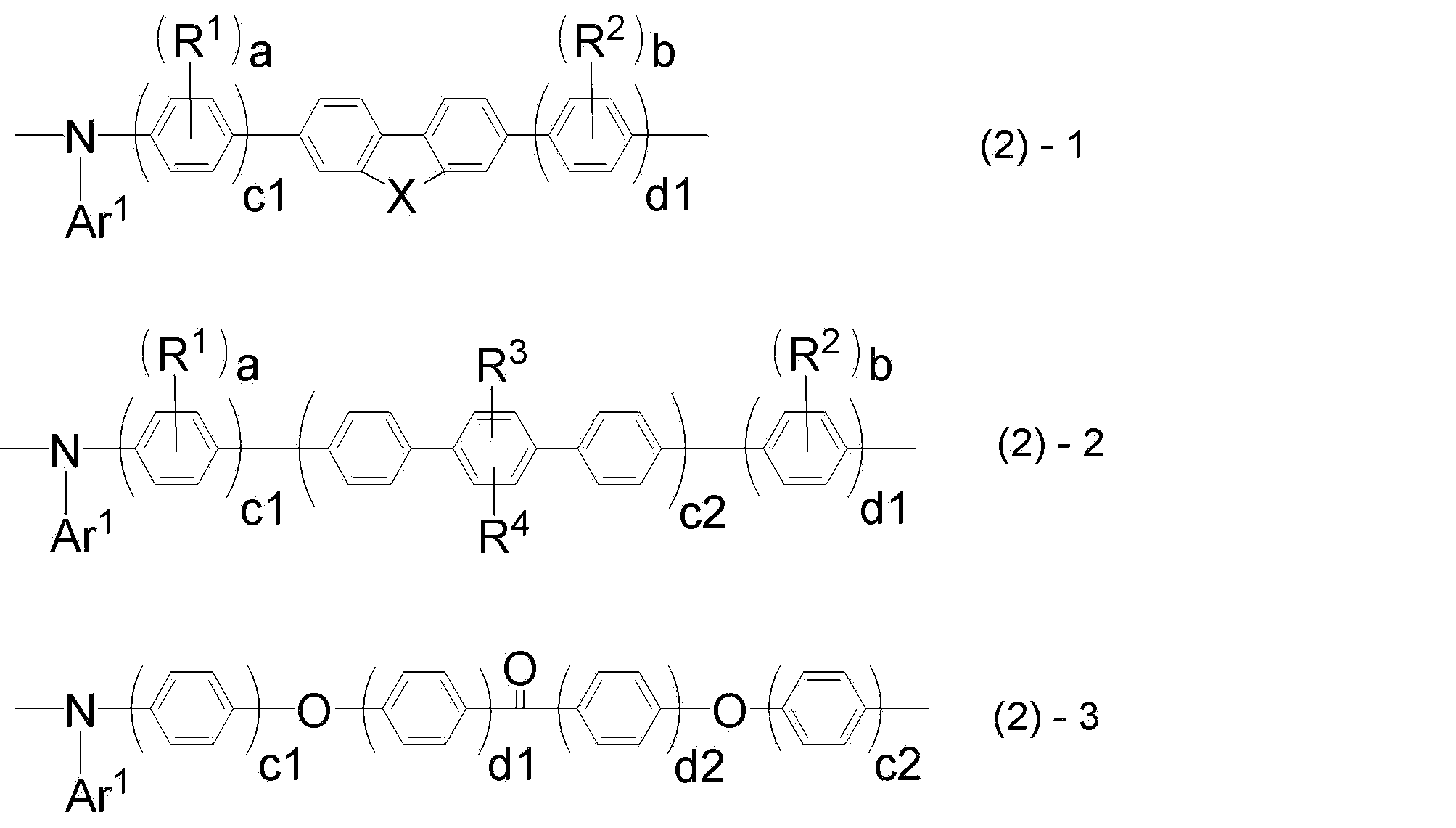
(式(2)-1~式(2)-3中、
Ar1は前記式(1)のAr1と同じであり、
Xは、-C(R5)(R6)-、-N(R7)-または-C(R11)(R12)-C(R13)(R14)-を表し、
R1~R4は、各々独立に、置換基を有していてもよいアルキル基、置換基を有していてもよいアルコキシ基、又は置換基を有していてもよいアラルキル基を表し、
R5~R7及びR11~R14は、各々独立に、置換基を有していてもよいアルキル基、置換基を有していてもよいアルコキシ基、置換基を有していてもよいアラルキル基、または置換基を有していてもよい芳香族炭化水素基を表し、
a、bは、各々独立に、0~4の整数であり、
c1、c2は、各々独立に、1~3の整数であり、
d1、d2は、各々独立に、0~4の整数であり、
R1、R2、R3、R4が該繰り返し単位中に複数ある場合は、R1、R2、R3、R4は同一であっても異なっていてもよい。)
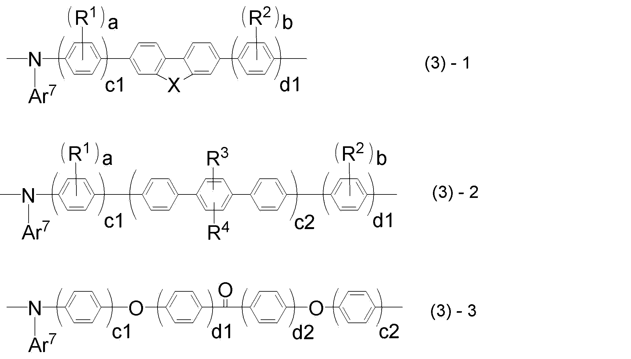
(式(3)-1~(3)-3中、
Ar7は、それぞれの繰り返し単位において独立に、置換基を有していてもよい芳香族炭化水素基、置換基を有していてもよい芳香族複素環基、又は置換基を有していてもよい芳香族炭化水素基若しくは置換基を有していてもよい芳香族複素環基が直接若しくは連結基を介して複数個連結した二価の基を表し、
X、R1、R2、R3、R4、a、b、c1、c2、d1、d2は、それぞれ前記式(2)-1~(2)-3と同じである。)
[7]前記重合体の重量平均分子量(Mw)が10,000以上であり、且つ、分散度(Mw/Mn)が3.5以下である、[1]~[6]のいずれかに記載の重合体。
[8][1]~[7]のいずれかに記載の重合体を含有する、有機電界発光素子用組成物。
[9]基板上に、陽極、陰極、及び該陽極と該陰極との間に有機層を有する有機電界発光素子の製造方法であって、
[8]に記載の有機電界発光素子用組成物を用いて、湿式成膜法により、該有機層を構成する層のうち少なくとも1層を形成する成膜ステップを含む、有機電界発光素子の製造方法。
[10]前記有機層が正孔注入層及び正孔輸送層を有し、該正孔注入層及び正孔輸送層のうちの少なくとも一つの層が、前記成膜ステップで形成される層である、[9]に記載の有機電界発光素子の製造方法。
[11]前記有機層がさらに、発光層を有し、
前記正孔注入層、正孔輸送層及び発光層が、前記成膜ステップで形成される層である、[9]又は[10]に記載の有機電界発光素子の製造方法。
[12]基板上に、陽極、陰極、及び該陽極と該陰極との間に有機層を有し、該有機層が[1]~[7]のいずれかに記載の重合体又は該重合体が架橋した重合体を含有する層を有する、有機電界発光素子。

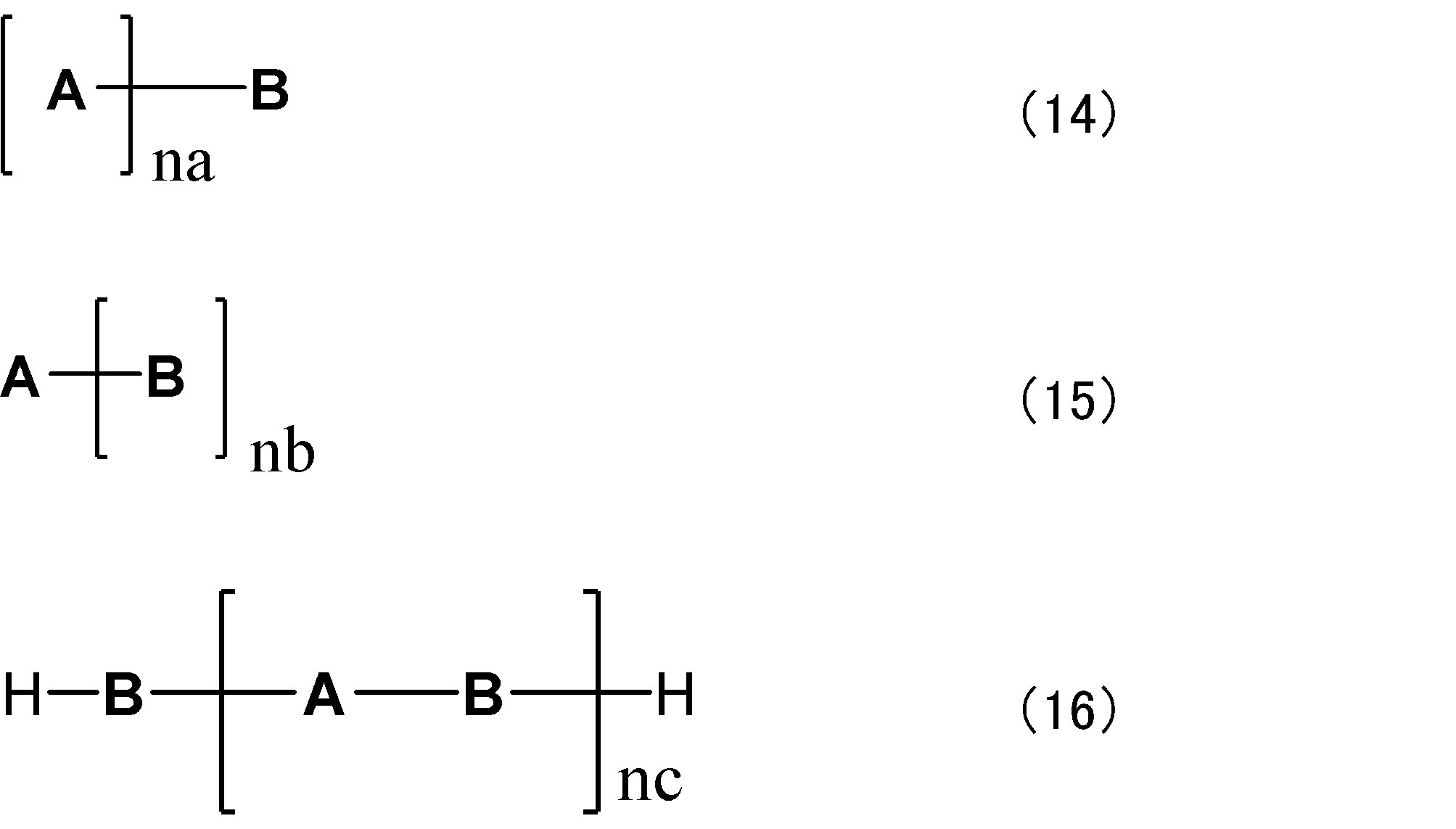
(式(14)~(16)中、
Aは前記式(CzP)で表される部分構造であり、置換基を有していてもよい。
Bは単結合または任意の部分構造を表す。
Aが複数存在する場合、同一であっても互いに異なっていてもよい。
Bが複数存在する場合、同一であっても互いに異なっていてもよい。
na、nb及びncは、それぞれ独立に、1以上、5以下の整数を表す。)
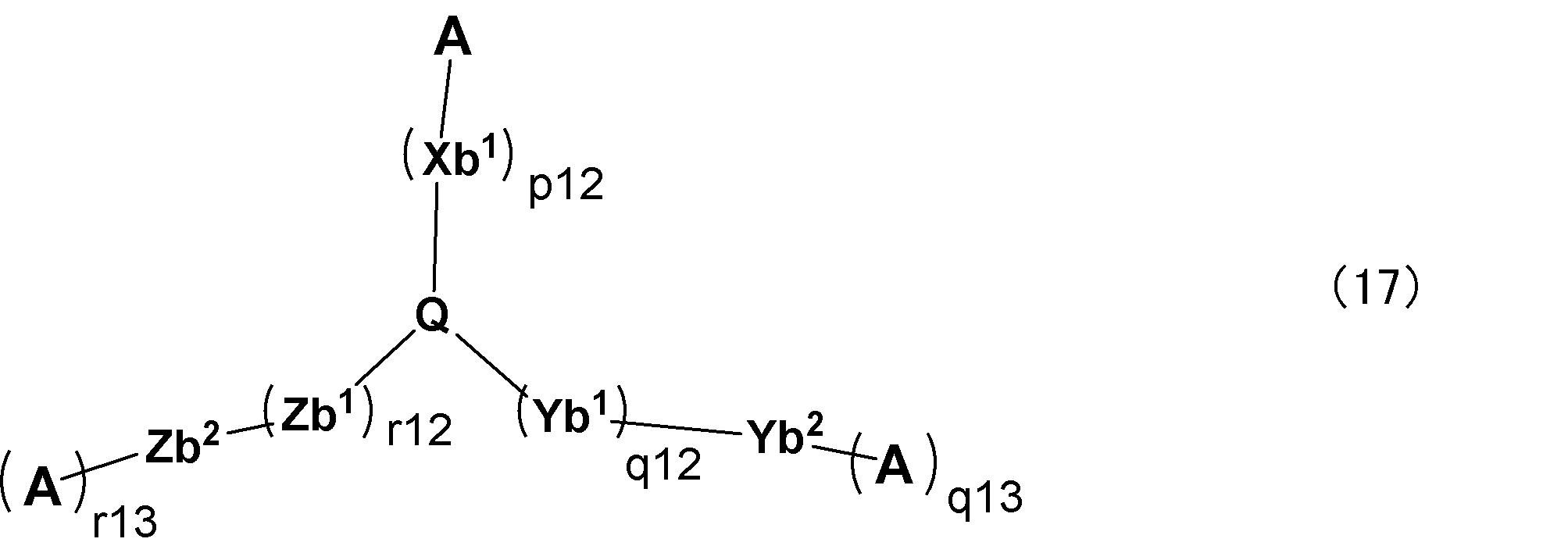
(上記式(17)において、
Qは、窒素原子または、下記構造式(18-1)~(18-3)のいずれかで表される3価の置換基のいずれかを表し、
Xb1、Yb1、及びZb1は、各々独立に、置換基を有していてもよい炭素数6~30の二価の炭化水素芳香環基、又は置換基を有していてもよい炭素数3~30の二価の複素芳香環基を表し、Xb1、Yb1、及びZb1のそれぞれはが複数存在する場合は同一であっても異なっていてもよく、
Aは、前記式(CzP)で表される部分構造であり、置換基を有していてもよく、かつ、複数存在するAは互いに同一であっても異なっていてもよく、
p12、q12、及びr12は、各々独立に、0以上6以下の整数を表し、
q13、r13は、各々独立に、0または1を表し、
q13が0の場合のYb2及び、r13が0の場合のZb2は各々独立に、水素原子、置換基を有していてもよい炭素数6~30の一価の炭化水素芳香環基、又は置換基を有していてもよい炭素数3~30の一価の複素芳香環基を表し、
q13が1の場合のYb2は直接結合であり、
r13が1の場合のZb2は直接結合であり
式(18-1)~(18-3)において、一つの構造式中の3つの*は、それぞれXb1、Yb1、又はZb1のいずれか基との結合位置を表す。)
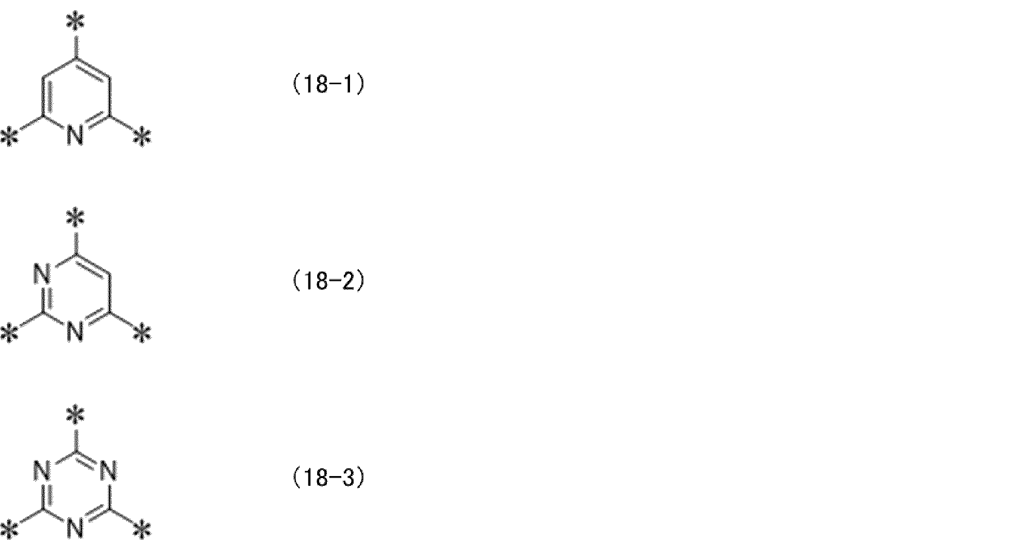

(上記式(19)中、
Xc1及びYc1は、各々独立に、置換基を有していてもよい炭素数6~30の二価の炭化水素芳香環基、又は置換基を有していてもよい炭素数3~30の二価の複素芳香環基を表し、
Xc2及びYc2は、各々独立に、水素原子、置換基を有していてもよい一価の炭素数6~30の炭化水素芳香環基、又は置換基を有していてもよい炭素数3~30の一価の複素芳香環基を表し、
Xc1及びYc1のそれぞれは複数存在する場合は同一であっても異なっていてもよく、
Aは前記式(CzP)で表される部分構造であり、置換基を有していてもよく、
s11及びt11は、各々独立に、0以上6以下の整数を表し、
ncは、1以上、5以下の整数を表す。)
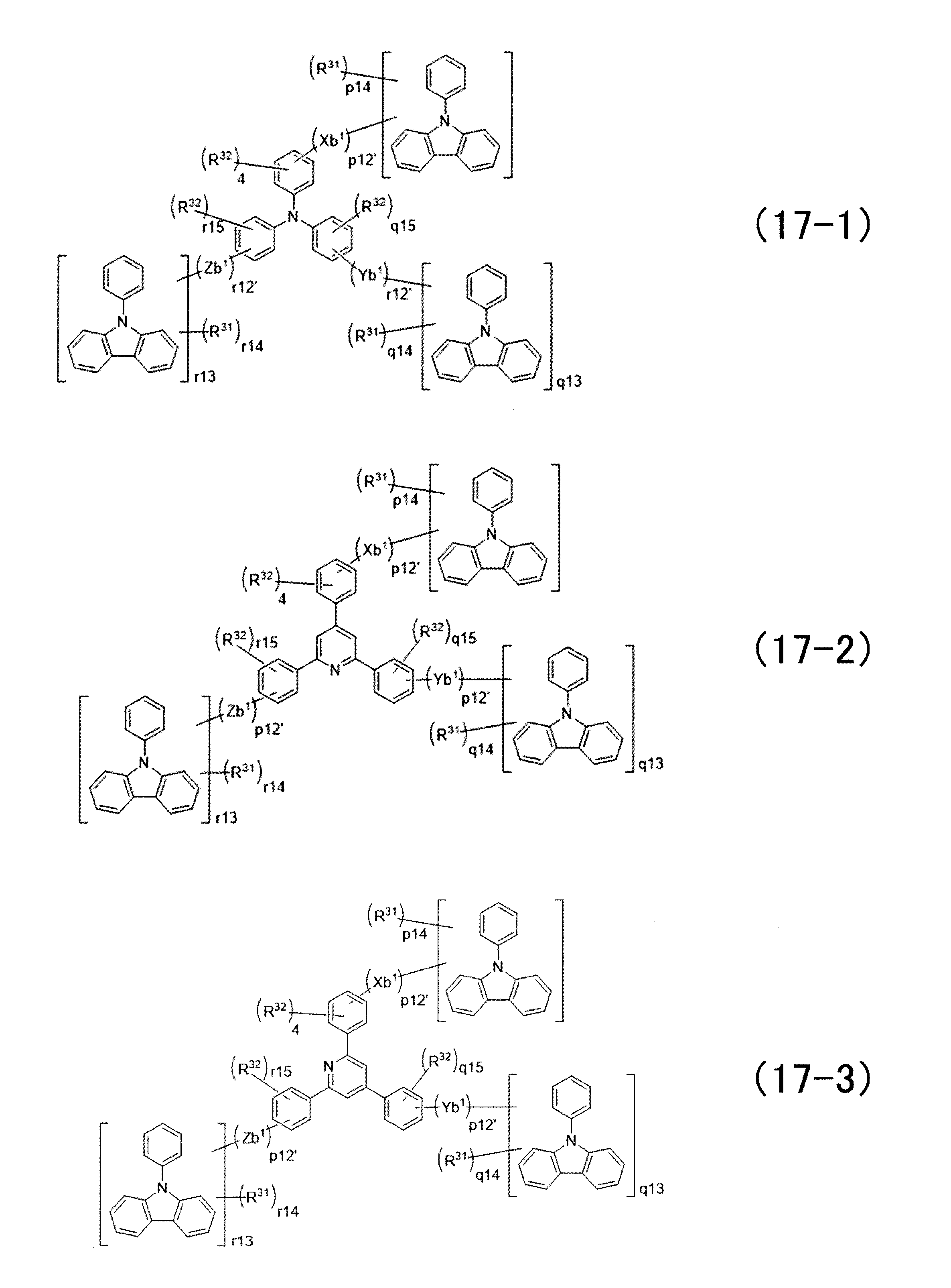
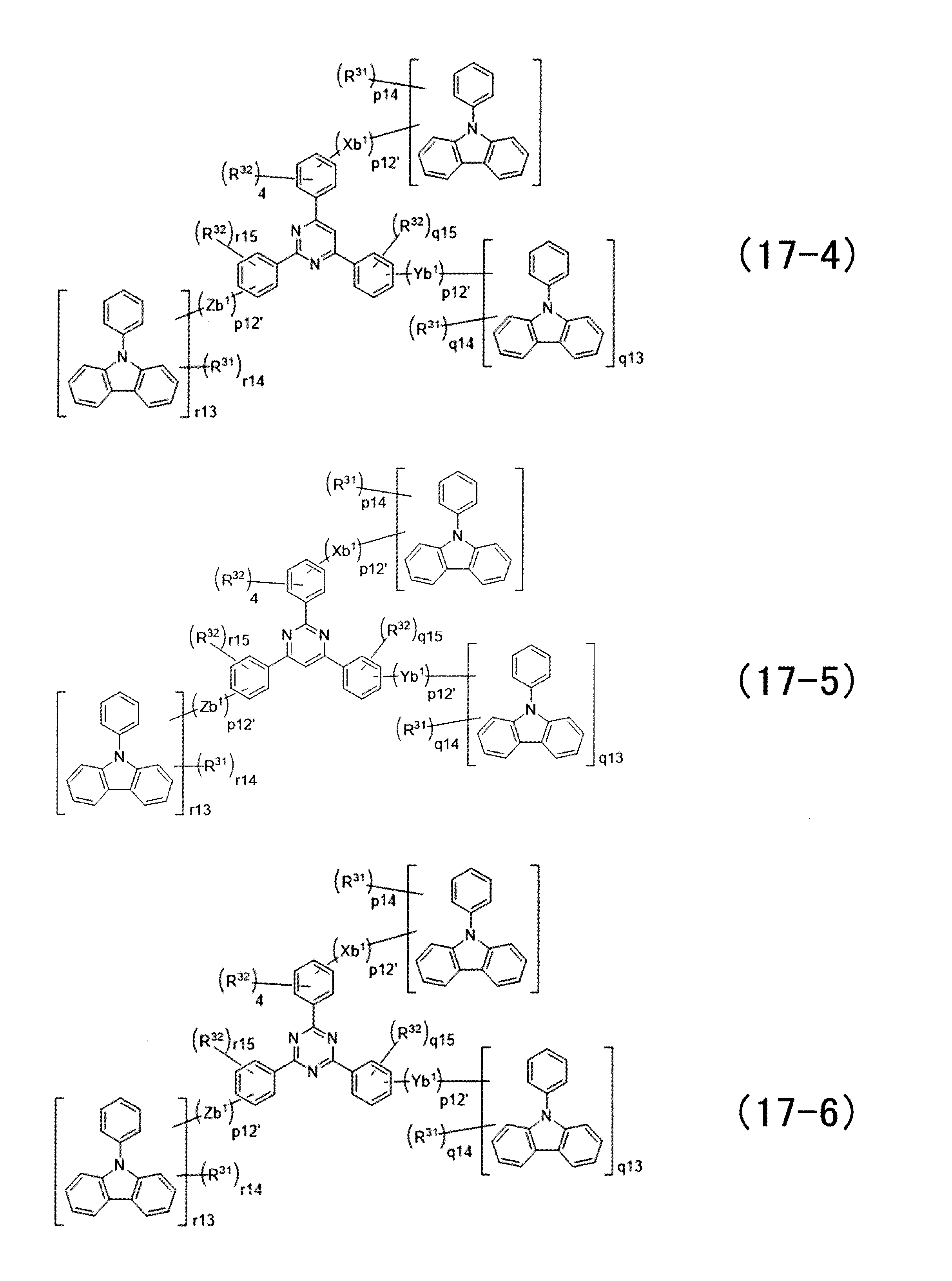
(上記一般式(17-1)~(17-6)中、
p12’は、1以上5以下の整数を表し、
q12’及びr12’は、各々独立に、0以上5以下の整数を表し、
p14は12であり、
q14はq13が1の場合は12であり、q13が0の場合は存在せず、
r14はr13が1の場合は12であり、r13が0の場合は存在せず、
q15及びr15は、各々独立に、4又は5であり、
R31及びR32は、各々独立に、水素原子または置換基であり、
Xb1、Yb1、Zb1、q13、r13は、それぞれ前記式(17)と同じである。)
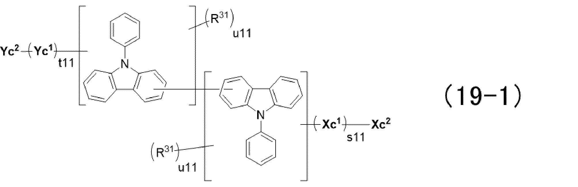
(上記一般式(19-1)において、
R31は、水素原子または置換基であり、
u11は、11を表し、
Xc1、Yc1、Xc1、Yc1、t11、及びs11は、それぞれ前記式(19)と同じである。)
[22][12]~[20]のいずれかに記載の有機電界発光素子を備える、有機EL照明。
また、本実施形態の重合体の主鎖にフェニレンと酸素原子と交互結合する構造を含むことによりπ共役系の広がりが阻害された主鎖構造を有するため、励起一重項エネルギー準位(S1)および励起三重項エネルギー準位(T1)が高い性質があり、発光励起子からのエネルギー移動による消光が抑制されるため発光効率に優れる。
これに対して、本実施形態のように発光層にある発光材料の励起子のエネルギー準位より高いエネルギー準位を有する電荷輸送材料は、発光材料の励起子を閉じ込める効果が高く好ましい。
また、本発明の実施形態にかかる有機電界発光素子は、電気化学的安定性に優れる為、上記の重合体を用いて形成された層を含む素子は、フラットパネル・ディスプレイ(例えばOAコンピュータ用や壁掛けテレビ)、車載表示素子、携帯電話表示や面発光体としての特徴を生かした光源(例えば、複写機の光源、液晶ディスプレイや計器類のバックライト光源)、表示板、標識灯への応用が考えられ、その技術的価値は大きいものである。
また、本明細書において、「~」を用いて表される数値範囲は、「~」の前後に記載された数値を下限値及び上限値として含む範囲を意味し、「A~B」は、A以上B以下であることを意味する。
また、本明細書において、2つ以上の対象を併せて説明する際に用いる「独立して」とは、それらの2つ以上の対象が同じであっても異なっていてもよいという意味で使用される。
<重合体>
第1の要旨に係る実施形態の重合体は、下記式(1)で表される構造を含む重合体である。本明細書では、この重合体を重合体1とも称する。

式(1)中、
Gは置換基を有していてもよい芳香族炭化水素基、置換基を有していてもよい芳香族複素環基、又はC原子、N原子、B原子若しくはP原子を表し、
Ar2~Ar4は、それぞれ独立に、置換基を有していてもよい二価の芳香族炭化水素基、置換基を有していてもよい芳香族複素環基、又は置換基を有していてもよい芳香族炭化水素基若しくは置換基を有していてもよい芳香族複素環基が直接若しくは連結基を介して複数個連結した二価の基を表し、
Ar5は置換基を有していてもよい芳香族炭化水素基、置換基を有していてもよい芳香族複素環基、又は置換基を有していてもよい芳香族炭化水素基若しくは芳香族複素環基が直接若しくは連結基を介して複数個連結した一価の基を表し、
Ar6は水素原子又は置換基を表す。
なお、Ar1中の“-*”が式(1)中Gと結合する部位(結合位置)である。
前記式(1)で表される繰り返し単位中において、Gは置換基を有していてもよい芳香族炭化水素基、置換基を有していてもよい芳香族複素環基、又はC原子、N原子、B原子若しくはP原子を表す。電荷輸送性が優れる点、カルバゾール環の9位に分布のLUMOと主鎖に分布したHOMOとが局在化される観点から、Gは置換基を有していてもよいベンゼン環、置換基を有していてもよいトリアジン環、置換基を有していてもよいフルオレン環、置換基を有していてもよいスピロフルオレン環、置換基を有していてもよいカルバゾール環が好ましく、下記スキーム1に示す構造がより好ましい。なお、下記構造は置換基を有していてもよい。また、図中、“-*”はAr3との結合位置を表わす。
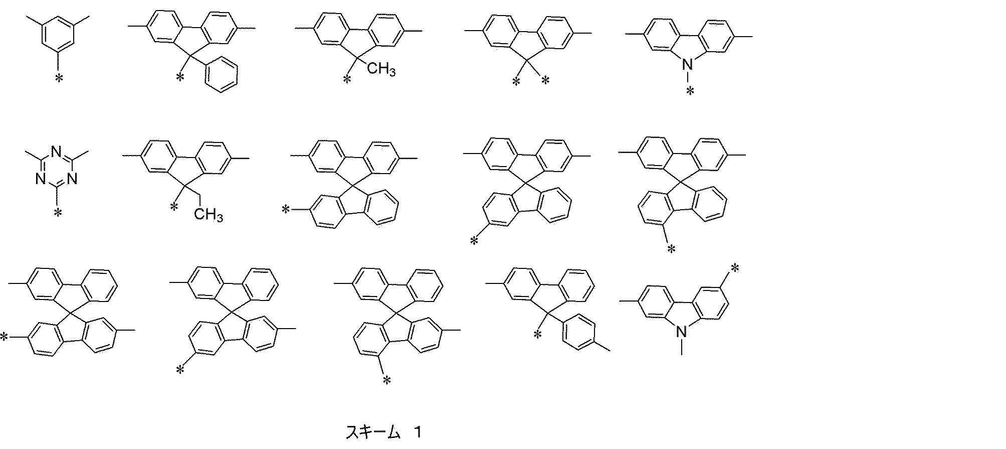
炭素数1~12のアルキル基、炭素数7~30のアラルキル基、炭素数3~27のヘテロ環のアラルキル基、炭素数6~24の芳香族炭化水素基、又は、炭素数3~24の芳香族複素環基であることがより好ましく、
炭素数6~24のアリール基であることが更に好ましい。
電荷輸送性の観点からは、出現する毎に同一であるかまたは異なり、炭素数6~24の芳香族炭化水素基、又は炭素数3~24の芳香族複素環基であることが好ましく、フェニル基、ナフチル基、フルオレニル基、カルバゾリル基、インドロカルバゾリル基、インデノカルバゾリル基、又はインデノフルオレニル基であることがさらに好ましい。
前記式(1)で表される繰り返し単位中において、Ar2~Ar4は、それぞれ独立に、置換基を有していてもよい二価の芳香族炭化水素基、置換基を有していてもよい二価の芳香族複素環基、又は置換基を有していてもよい芳香族炭化水素基若しくは置換基を有していてもよい芳香族複素環基が直接若しくは連結基を介して複数個連結した二価の基を表す。
芳香族炭化水素基としては、炭素数が6以上、60以下が好ましく、具体的には、ベンゼン環、ナフタレン環、アントラセン環、フェナントレン環、ペリレン環、テトラセン環、ピレン環、ベンズピレン環、クリセン環、トリフェニレン環、アセナフテン環、フルオランテン環、フルオレン環等の、6員環の単環若しくは2~5縮合環の二価の基またはこれらが複数連結した二価の基が挙げられる。
上記の二価の基が複数個連結される場合は、2~10連結した二価の基が挙げられ、2~5連結した二価の基であることが好ましい。
上記の二価の基が複数個連結される場合は、2~10連結した二価の基が挙げられ、2~5連結した二価の基であることが好ましい。
上記の二価の基が複数個連結される場合は、2~10連結した二価の基が挙げられ、2~5連結した二価の基であることが好ましい。
Ar5は、置換基を有していてもよい芳香族炭化水素基、置換基を有していてもよい芳香族複素環基、又は置換基を有していてもよい芳香族炭化水素基及び該置換基を有していてもよい芳香族複素環基から選択される基が直接若しくは連結基を介して複数個連結した一価の基である。複数個連結する場合は、2~10連結した二価の基が挙げられ、2~5連結した二価の基であることが好ましい。芳香族炭化水素、芳香族複素環としては、前記Ar2~Ar4で挙げた芳香族炭化水素構造、芳香族複素環構造であって一価である構造を用いることができる。式(1)のAr1に明記されているカルバゾール環の9位に、下記スキーム2のいずれかで表される構造を有することが好ましい。更には、分子のLUMOを分布させる観点からa-1~a-4、b-1~b-9、c-1~c-5、d-1~d-16、及びe1~e4から選択される構造が好ましい。更に電子求引性基を有することにより分子のLUMOが広がることに促進する観点から、a-1~a-4、b-1~b-9、d-1~d-13、及びe1~e4から選択される構造が好ましい。更に三重項レベルが高い、発光層に形成された励起子を閉じ込む効果の観点から、a-1~a-4、d-1~d-13、及びe1~e4から選択される構造が好ましい。また、フェニル基であることも好ましい。更にこれら構造に置換基を有していてもよい。なお、図中“-*”はAr4との結合位置を表わし、“-*”が複数ある場合はいずれか一つがAr4との結合位置を表す。
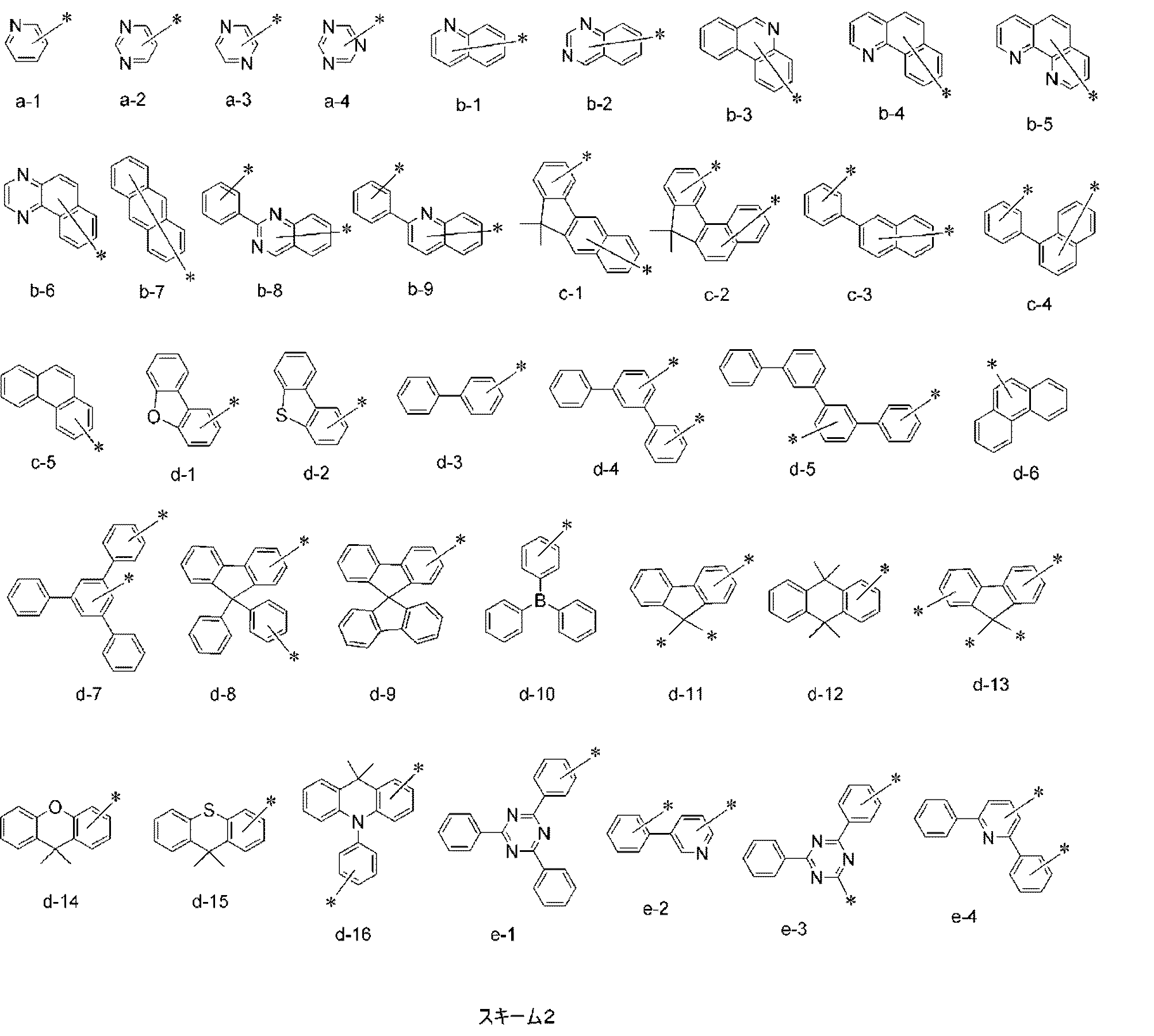
Ar6は、水素原子または置換基を表す。Ar6が置換基である場合、特に限定はされないが、好ましくは置換基を有していてもよい芳香族炭化水素基又は置換基を有していてもよい芳香族複素環基である。好ましい構造としては、前記Ar2~Ar4で挙げた芳香族炭化水素構造、芳香族複素環構造と同様であって一価である構造である。
Ar6が置換基である場合、カルバゾールの3位に結合していることが、耐久性向上の観点から好ましい。Ar6は、合成のし易さ及び電荷輸送性の観点からは、水素原子であることが好ましい。Ar6は、耐久性向上及び電荷輸送性の観点からは、置換基を有していてもよい芳香族炭化水素基又は置換基を有していてもよい芳香族複素環基であることが好ましく、置換基を有していてもよい芳香族炭化水素基であることがさらに好ましい。
中でも、前記式(1)は、下記式(2)-1~式(2)-3のいずれかで表される繰り返し単位であることがより好ましい。
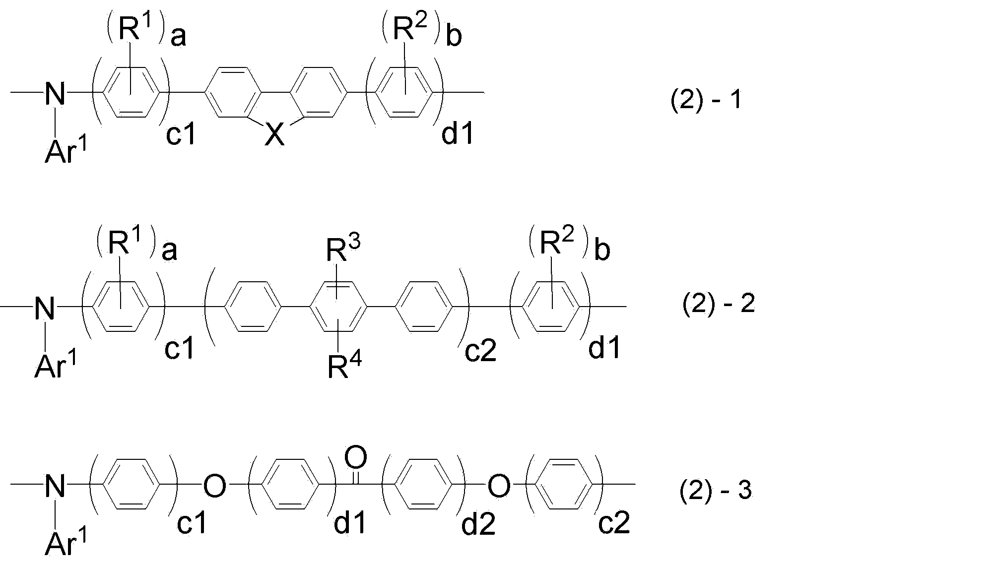
Ar1は、式(1)のAr1と同じであり、
Xは、-C(R5)(R6)-、-N(R7)-または-C(R11)(R12)-C(R13)(R14)-を表し、
R1~R4は、各々独立に、置換基を有していてもよいアルキル基、置換基を有していてもよいアルコキシ基、置換基を有していてもよいアラルキル基を表し、
R5~R7及びR11~R14は、各々独立に、置換基を有していてもよいアルキル基、置換基を有していてもよいアルコキシ基、置換基を有していてもよいアラルキル基、または置換基を有していてもよい芳香族炭化水素基を表し、
a、bは、各々独立に、0~4の整数であり、
c1、c2は、各々独立に、1~3の整数であり、
d1、d2は、各々独立に、0~4の整数であり、
R1、R2、R3、R4が該繰り返し単位中に複数ある場合は、R1、R2、R3、R4は同一であっても異なっていてもよい。
Xは、-C(R5)(R6)-、-N(R7)-または-C(R11)(R12)-C(R13)(R14)-のいずれかである。耐久性の観点から好ましくは-C(R5)(R6)-、-N(R7)-である。
上記式(2)-1~式(2)-3で表される繰り返し単位中のR1及びR2は、各々独立に、置換基を有していてもよい直鎖、分岐又は環状のアルキル基であることが好ましい。アルキル基の炭素数は特に限定されないが、重合体の溶解性を維持するために、炭素数が1以上、6以下が好ましく、3以下がより好ましく、メチル基又はエチル基であることがさらに好ましい。
R1及びR2が該繰り返し単位中に複数ある場合は、R1及びR2は同一であっても異なっていてもよいが、電荷を均一的に窒素原子の周りに分布することができ、さらに合成も容易であることから、全てのR1及びR2は同一の基であることが好ましい。
上記式(2)-1~式(2)-3で表される繰り返し単位中のR3及びR4は、各々独立に、置換基を有していてもよい直鎖、分岐又は環状のアルキル基であることが好ましい。アルキル基の炭素数は特に限定されないが、重合体の溶解性を維持するために、炭素数が1以上であることが好ましく、4以上がより好ましく、炭素数12以下が好ましく、さらに好ましくは8以下であり、ヘキシル基であることが特に好ましい。
R5~R7及びR11~R14は、各々独立に、置換基を有していてもよいアルキル基、置換基を有していてもよいアルコキシ基、置換基を有していてもよいアラルキル基、又は置換基を有していてもよい芳香族炭化水素基であることが好ましい。
具体的には、メチル基、エチル基、n-プロピル基、i-プロピル基、n-ブチル基、i-ブチル基、sec-ブチル基、tert-ブチル基、n-ヘキシル基、n-オクチル基、シクロヘキシル基、ドデシル基等が挙げられる。
具体的には、メトキシ基、エトキシ基、n-プロポキシ基、i-プロポキシ基、n-ブトキシ基、i-ブトキシ基、tert-ブトキシ基、ヘキシルオキシ基等が挙げられる。
具体的には、1,1-ジメチル-1-フェニルメチル基、1,1-ジ(n-ブチル)-1-フェニルメチル基、1,1-ジ(n-ヘキシル)-1-フェニルメチル基、1,1-ジ(n-オクチル)-1-フェニルメチル基、フェニルメチル基、フェニルエチル基、3-フェニル-1-プロピル基、4-フェニル-1-n-ブチル基、1-メチル-1-フェニルエチル基、5-フェニル-1-n-プロピル基、6-フェニル-1-n-ヘキシル基、6-ナフチル-1-n-ヘキシル基、7-フェニル-1-n-ヘプチル基、8-フェニル-1-n-オクチル基、4-フェニルシクロヘキシル基等が挙げられる。
具体的には、ベンゼン環、ナフタレン環、アントラセン環、フェナントレン環、ペリレン環、テトラセン環、ピレン環、ベンズピレン環、クリセン環、トリフェニレン環、アセナフテン環、フルオランテン環、フルオレン環等の、6員環の単環又は2~5縮合環の一価の基、またはこれらから選ばれる環構造が2~8連結した基が挙げられ、好ましくは単環又は2乃至4以下連結した基である。
溶解性を向上しつつ電荷輸送性に優れる点では、R5及びR6は炭素数3以上8以下のアルキル基又は炭素数9以上40以下のアラルキル基が好ましい。
前記R1~R4のアルキル基、R5~R7及びR11~R14のアルキル基、アルコキシ基、アラルキル基及び芳香族炭化水素基は、低電圧化の観点からは、置換基を有さないことが最も好ましい。
前記式(2)-1~式(2)-3で表される繰り返し単位中において、a及びbは各々独立に、0~4の整数である。また、a+bは1以上であることが好ましい。さらに、a及びbは、各々2以下であることが好ましく、aとbの両方が1であることがさらに好ましい。
ここで、R1とR2とが互いに対称な位置に結合するということについて、前記式(2)-1においてX=Cである場合を例にとり、下記式にて説明する。すなわち、下記式における主鎖のフルオレン環に対して、R1とR2の結合位置が対象であることをいう。このとき、主鎖を軸とする180度回転は同一構造とみなす。例えば、式(1a)において、RaとRbとが対象、Ra’とRb’とが対象であり、式(1a)と式(1b)とは同一構造とみなす。
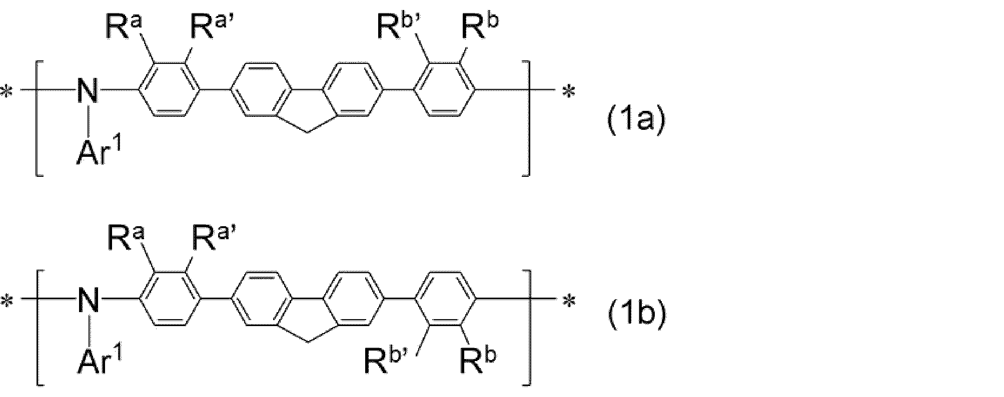
置換基群Zとして、以下の構造が挙げられる。
例えば、メチル基、エチル基、n-プロピル基、i-プロピル基、n-ブチル基、i-ブチル基、sec-ブチル基、tert-ブチル基、n-ヘキシル基、シクロヘキシル基、ドデシル基等の、炭素数が通常1以上であり、好ましくは4以上であり、通常24以下、好ましくは12以下である、直鎖、分岐、又は環状のアルキル基;
例えば、ビニル基等の、炭素数が通常2以上であり、通常24以下、好ましくは12以下であるアルケニル基;
例えば、エチニル基等の、炭素数が通常2以上であり、通常24以下、好ましくは12以下であるアルキニル基;
例えば、メトキシ基、エトキシ基等の、炭素数が通常1以上であり、通常24以下、好ましくは12以下であるアルコキシ基;
例えば、フェノキシ基、ナフトキシ基、ピリジルオキシ基等の、炭素数が通常4以上、好ましくは5以上であり、通常36以下、好ましくは24であるアリールオキシ基若しくはヘテロアリールオキシ基;
例えば、メトキシカルボニル基、エトキシカルボニル基等の、炭素数が通常2以上であり、通常24以下、好ましくは12以下であるアルコキシカルボニル基;
例えば、ジメチルアミノ基、ジエチルアミノ基等の、炭素数が通常2以上であり、通常24以下、好ましくは12以下であるジアルキルアミノ基;
例えば、ジフェニルアミノ基、ジトリルアミノ基、N-カルバゾリル基等の、炭素数が通常10以上、好ましくは12以上であり、通常36以下、好ましくは24以下のジアリールアミノ基;
例えば、フェニルメチルアミノ基等の、炭素数が通常7以上であり、通常36以下、好ましくは24以下であるアリールアルキルアミノ基;
例えば、アセチル基、ベンゾイル基等の、炭素数が通常2以上であり、通常24以下、好ましくは12以下であるアシル基;
例えば、フッ素原子、塩素原子等のハロゲン原子;
例えば、トリフルオロメチル基等の、炭素数が通常1以上であり、通常12以下、好ましくは6以下のハロアルキル基;
例えば、メチルチオ基、エチルチオ基等の、炭素数が通常1以上であり、通常24以下、好ましくは12以下のアルキルチオ基;
例えば、フェニルチオ基、ナフチルチオ基、ピリジルチオ基等の、炭素数が通常4以上、好ましくは5以上であり、通常36以下、好ましくは24以下であるアリールチオ基;
例えば、トリメチルシリル基、トリフェニルシリル基等の、炭素数が通常2以上、好ましくは3以上であり、通常36以下、好ましくは24以下であるシリル基;
例えば、トリメチルシロキシ基、トリフェニルシロキシ基等の、炭素数が通常2以上、好ましくは3以上であり、通常36以下、好ましくは24以下であるシロキシ基;
シアノ基;
例えば、フェニル基、ナフチル基等の、炭素数が通常6以上であり、通常36以下、好ましくは24以下である芳香族炭化水素基;
例えば、チエニル基、ピリジル基等の、炭素数が通常3以上、好ましくは4以上であり、通常36以下、好ましくは24以下である芳香族複素環基。
上記の置換基群Zの中でも、好ましくは、前記アルキル基、アルコキシ基、芳香族炭化水素基、芳香族複素環基である。電荷輸送性の観点からは、置換基を有さないことがさらに好ましい。
本実施形態において、末端基とは、重合体の重合終了時に用いたエンドキャップ剤によって形成された、重合体の末端部の構造のことを指す。本実施形態の重合体の末端基は、通常炭化水素基である。炭化水素基としては、電荷輸送性の観点から、炭素数1以上60以下が好ましく、1以上40以下がより好ましく、1以上30以下がさらに好ましい。
例えば、メチル基、エチル基、n-プロピル基、i-プロピル基、n-ブチル基、i-ブチル基、sec-ブチル基、tert-ブチル基、n-ヘキシル基、シクロヘキシル基、ドデシル基等の、炭素数が通常1以上であり、好ましくは4以上であり、通常24以下、好ましくは12以下である、直鎖、分岐、又は環状のアルキル基;
例えば、ビニル基等の、炭素数が通常2以上であり、通常24以下、好ましくは12以下であるアルケニル基;
例えば、エチニル基等の、炭素数が通常2以上であり、通常24以下、好ましくは12以下であるアルキニル基;
例えば、フェニル基、ナフチル基等の、炭素数が通常6以上であり、通常36以下、好ましくは24以下である芳香族炭化水素環基;
が挙げられる。
これら炭化水素基はさらに置換基を有していてもよく、さらに有していてもよい置換基はアルキル基又は芳香族炭化水素基が好ましく、これらさらに有していてもよい置換基が複数ある場合は互いに結合して環を形成していてもよい。
好ましくは、電荷輸送性および耐久性の観点から、アルキル基又は芳香族炭化水素基であり、更に好ましくは芳香族炭化水素基である。
本実施形態の重合体は、溶媒への可溶性発現のため可溶性基を有することが好ましい。本実施形態における可溶性基は、炭素数3以上24以下、好ましくは炭素数12以下の、直鎖又は分岐のアルキル基またはアルキレン基を有する基である。これらの中でも好ましくは、アルキル基、アルコキシ基、またはアラルキル基であり、例えば、n-プロピル基、2-プロピル基、n-ブチル基、イソブチル基等である。より好ましくはn-ヘキシル基又はn-オクチル基である。可溶性基は置換基を有していてもよい。前記R1~R7及びR11~R14の一つ又は複数がこれらの構造である場合、それらの基は可溶性基であるとみなす。また、本実施形態における置換基が前記可溶性基の条件を満たす場合、それらの置換基は可溶性基であるとみなす。
本実施形態の重合体が有する可溶性基は、湿式成膜法に利用可能な重合体溶液を得やすくなる点では、多い方が好ましい。一方で、成膜した層の上に湿式成膜法で他の層を形成した際に層が溶媒に溶解してしまうことによる膜厚減少が少ない点では、少ない方が好ましい。
本実施形態の重合体が有する可溶性基の数を、重合体の1gあたりのモル数で表した場合、重合体1gあたり、通常4.0ミリモル以下、好ましくは3.0ミリモル以下、さらに好ましくは2.0ミリモル以下であり、また通常0.1ミリモル以上、好ましくは0.5ミリモル以上である。
可溶性基の数が上記範囲内であると、重合体が溶媒に溶解しやすく、湿式成膜法に適した重合体を含む組成物が得られ易い。また、可溶性基密度が適度であるため、加熱溶媒乾燥後の有機溶媒に対する難溶性が十分であるため、湿式成膜法での多層積層構造が形成可能となる。
以下に示す、後述の実施例1で合成した重合体1の場合で説明すると、重合体1において、末端基を除いた繰り返し単位の分子量は平均767であり、また可溶性基であるヘキシル基は、1繰り返し単位当たり平均2個である。これを単純比例により計算すると、分子量1gあたりの可溶性基の数は、2.09ミリモルと算出される。
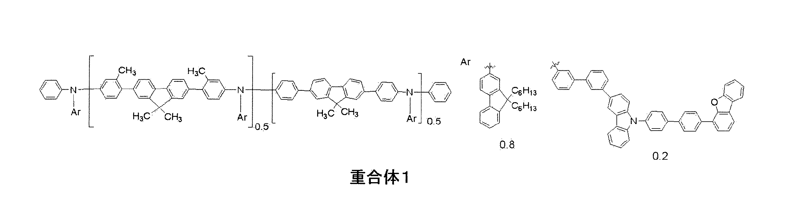
本実施形態の重合体は、置換基として架橋性基を有していてもよい。本実施形態の重合体における架橋性基は、式(1)で表される繰り返し単位中に存在していてもよく、式(1)で表される繰り返し単位とは別の繰り返し単位中に存在していてもよい。特に、側鎖であるAr1に架橋性基を有することが、架橋反応が進行しやすいため好ましい。
架橋性基を有することで、熱及び/又は活性エネルギー線の照射により起こる反応(難溶化反応)の前後で、有機溶媒に対する溶解性に大きな差を生じさせることができる。
架橋性基としては、芳香族環に縮環したシクロブテン環、芳香族環に結合したアルケニル基を含む基が好ましく、更に好ましくは下記架橋性基群Tから選ばれる基である。架橋性基は、前記各構造が有する置換基にさらに置換していることが好ましい。
架橋性基群Tは、以下に示す構造である。
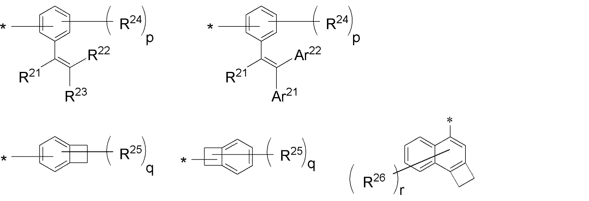
R21~R23は、各々独立に、水素原子又はアルキル基を表す。
R24~R26は、各々独立に、アルキル基又はアルコキシ基を表す。pは1~4の整数、qは1~5の整数、rは1~7の整数を表す。
pが2以上のとき、複数のR24は同じであっても異なっていてもよく、隣接するR24同士が結合して環を形成してもよい。
qが2以上のとき、複数のR25は同じであっても異なっていてもよく、隣接するR25同士が結合して環を形成してもよい。
rが2以上のとき、複数のR26は同じであっても異なっていてもよい。
Ar21、Ar22は置換基を有していてもよい、芳香族炭化水素基又は芳香族複素環基を表す。
Ar22は、置換基を有していてもよい芳香族炭化水素基を2以上結合させた基であってもよい。このような基としては、ビフェニレン基、ターフェニレン基等が挙げられ、4,4’-ビフェニレン基が好ましい。
Ar21、Ar22が有していてもよい置換基は前述の置換基群Zと同様である。
また、架橋性基の中でも、架橋後の構造が特に安定な点で、一価の遊離原子価を有する芳香族環に縮環したシクロブテン環、一価の遊離原子価を有する1,2-ジヒドロシクロブタ〔a〕ナフタレン環を含む基が好ましく、中でもベンゾシクロブテン環または一価の遊離原子価を有する1,2-ジヒドロシクロブタ〔a〕ナフタレン環が更に好ましく、架橋反応温度が低い点で一価の遊離原子価を有する1,2-ジヒドロシクロブタ〔a〕ナフタレン環が特に好ましい。
本実施形態の重合体が有する架橋性基は、架橋することにより十分に不溶化し、その上に湿式成膜法で他の層を形成しやすくなる点では、多い方が好ましい。一方で、形成された層にクラックが生じ難く、未反応架橋性基が残りにくく、有機電界発光素子が長寿命になりやすい点では、架橋性基は少ないことが好ましい。
また、本実施形態の重合体が有する架橋性基の数は、重合体の分子量1000あたりの数で表すことができる。
本実施形態の重合体が有する架橋性基の数を、重合体の分子量1000あたりの数で表した場合、分子量1000あたり、通常3.0個以下、好ましくは2.0個以下、さらに好ましくは1.0個以下であり、また通常0.01個以上、好ましくは0.05個以上である。
架橋性基の数が上記範囲内であると、クラック等が起き難く、平坦な膜が得られ易い。また、架橋密度が適度であるため、架橋反応後の層内に残る未反応の架橋性基が少なく、得られる素子の寿命に影響し難い。
さらに、架橋反応後の、有機溶媒に対する難溶性が十分であるため、湿式成膜法での多層積層構造が形成し易い。
例えば、後述の実施例で合成した重合体3の場合で説明すると、重合体3において、末端基を除いた繰り返し単位の分子量は平均816であり、また架橋性基は、1繰り返し単位当たり0.138個である。これを単純比例により計算すると、分子量1000あたりの架橋性基の数は、0.15個と算出される。
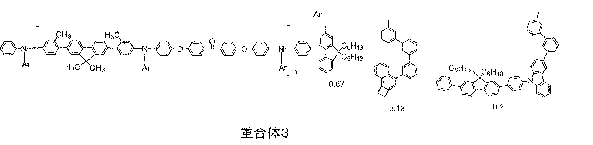
本実施形態の重合体において、式(1)で表される繰り返し単位の含有量は特に制限されないが、通常重合体中に50モル%以上含まれ、60モル%以上含まれることが好ましく、70モル%以上含まれることがさらに好ましく、80モル%以上含まれることが特に好ましい。本実施形態の重合体は、繰り返し単位が、式(1)で表される繰り返し単位のみから構成されていてもよいが、有機電界発光素子とした場合の諸性能をバランスさせる目的から、式(1)とは別の繰り返し単位を有していてもよく、その場合、重合体中の式(1)で表される繰り返し単位の含有量は、通常、95モル%以上、好ましくは99モル%以上である。
本実施形態の重合体は、さらに下記(3)-1~式(3)-3のいずれかで表わされる繰り返し単位を含むことも好ましい。
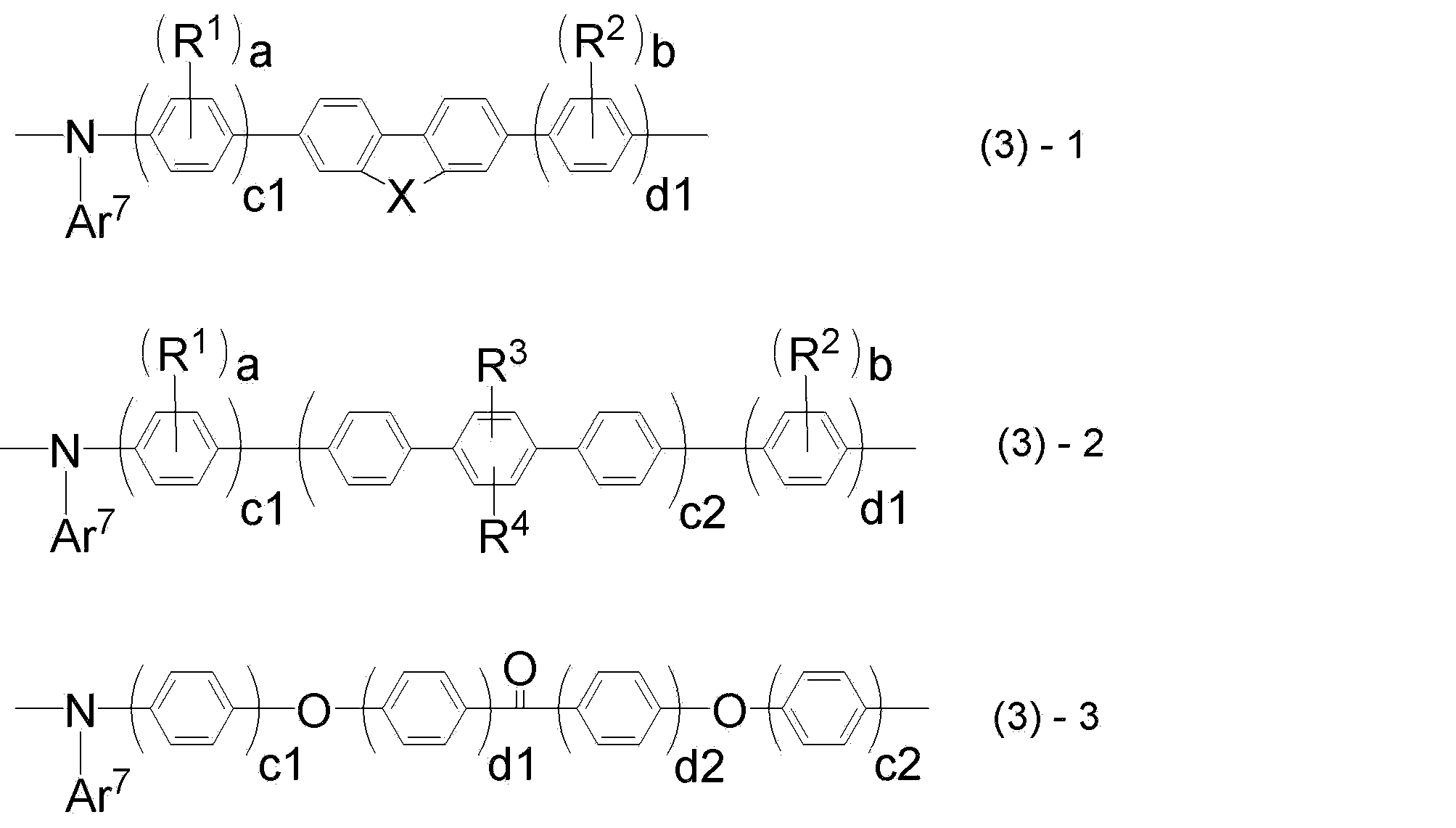
Ar7は、それぞれの繰り返し単位において独立に、置換基を有していてもよい芳香族炭化水素基、置換基を有していてもよい芳香族複素環基、又は置換基を有していてもよい芳香族炭化水素基若しくは置換基を有していてもよい芳香族複素環基が直接若しくは連結基を介して複数個連結した二価の基を表し、
Xは、-C(R5)(R6)-、-N(R7)-または-C(R11)(R12)-C(R13)(R14)-を表し、
R1~R4は、各々独立に、置換基を有していてもよいアルキル基、置換基を有していてもよいアルコキシ基、置換基を有していてもよいアラルキル基を表し、
R5~R7及びR11~R14は、各々独立に、置換基を有していてもよいアルキル基、置換基を有していてもよいアルコキシ基、置換基を有していてもよいアラルキル基、または置換基を有していてもよい芳香族炭化水素基を表し、
a、bは、各々独立に、0~4の整数であり、
c1、c2は、各々独立に、1~3の整数であり、
d1、d2は、各々独立に、0~4の整数であり、
R1、R2、R3、R4が該繰り返し単位中に複数ある場合は、R1、R2、R3、R4は同一であっても異なっていてもよい。
前記式(3)-1~(3)-3で表される繰り返し単位中において、Ar7は、それぞれの繰り返し単位において独立に、置換基を有していてもよい芳香族炭化水素基又は置換基を有していてもよい芳香族複素環基を表す。
芳香族炭化水素基としては、炭素数が6以上、60以下が好ましく、具体的には、ベンゼン環、ナフタレン環、アントラセン環、フェナントレン環、ペリレン環、テトラセン環、ピレン環、ベンズピレン環、クリセン環、トリフェニレン環、アセナフテン環、フルオランテン環、フルオレン環等の、6員環の単環若しくは2~5縮合環またはこれらが複数連結した一価の基が挙げられる。
上記の二価の基が複数個連結される場合は、2~10連結した二価の基が挙げられ、2~5連結した二価の基であることが好ましい。
上記の二価の基が複数個連結される場合は、2~10連結した二価の基が挙げられ、2~5連結した二価の基であることが好ましい。
また、Ar7は前述の架橋性基を含むことが、成膜後、積層塗布する際に溶媒に対する不溶性が向上するため好ましい。
有機電界発光素子に用いた場合の素子の耐久性または低電圧化の観点から、式(3)-1または式(3)-2で表される繰り返し単位を含むことが好ましい。
本実施形態の重合体の重量平均分子量(Mw)は、通常3,000,000以下、好ましくは1,000,000以下、より好ましくは500,000以下、さらに好ましくは200,000以下、特に好ましくは100,000以下である。また、通常10,000以上、好ましくは20,000以上、より好ましくは30,000以上である。
本実施形態の重合体は、電荷輸送性及び耐久性の点で、さらに式(4)または式(5)で表される繰り返し単位を含んでいてもよい。下記式(4)で表される繰り返し単位は、上記式(1)、式(2)-1~式(2)-3及び式(3)-1~式(3)-3で表わされる繰り返し単位中の一部の構造部分と一致しうるが、それらとは別の繰り返し単位の構造である。
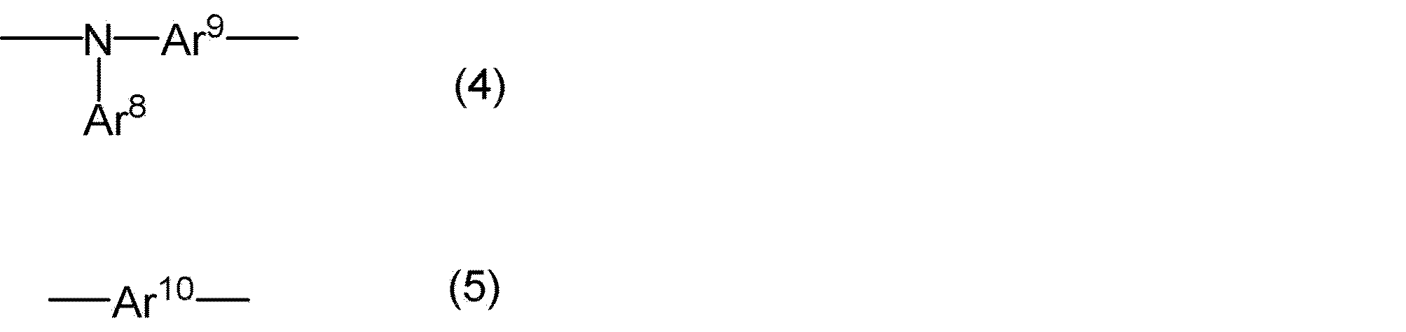
Ar8は、置換基を有していてもよい芳香族炭化水素基又は置換基を有していてもよい芳香族複素環基を表し、
Ar9は、置換基を有していてもよい二価の芳香族炭化水素基、置換基を有していてもよい二価の芳香族複素環基、又は該置換基を有していてもよい芳香族炭化水素基及び該置換基を有していてもよい芳香族複素環基から選ばれる複数の基が直接若しくは連結基を介して複数個連結した二価の基を表す。
Ar10は置換基を有していてもよい二価の芳香族炭化水素基、置換基を有していてもよい二価の芳香族複素環基、又は該置換基を有していてもよい芳香族炭化水素基及び該置換基を有していてもよい芳香族複素環基から選ばれる複数の基が直接若しくは連結基を介して複数個連結した二価の基を表す。
Ar8、Ar9及びAr10における芳香族炭化水素基及び芳香族複素環基としては、Ar8は式(1)のAr6が取ることのできる芳香族炭化水素基及び芳香族複素環基と同様の基から選択される基であり、Ar9及びAr10は式(1)Ar2が取ることのできる芳香族炭化水素基及び芳香族複素環基と同様の基から選択される基であって二価である基を表す。これらの二価の基が複数個連結される場合も同様に2~10が好ましく、2~5がさらに好ましい。有していてもよい置換基は前記置換基群Zまたは前記架橋性基と同様の基が好ましい。
本実施形態の重合体は、下記式(6)内のいずれかで示される繰り返し単位であることが最も好ましい。
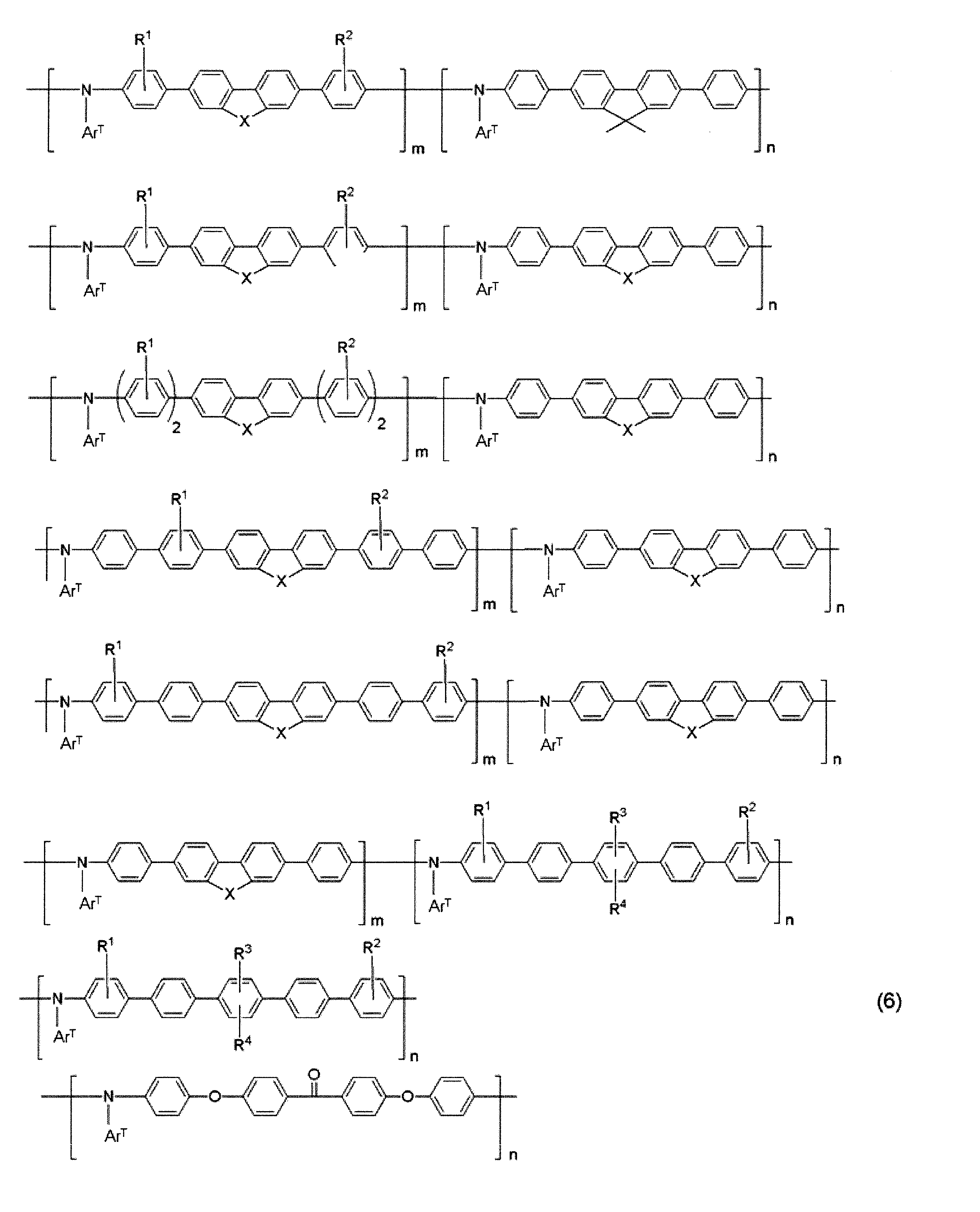
ArTは前記Ar1または前記Ar7を表し、各重合体中の複数のArTは同じであっても異なっていてもよく、各重合体中のArTの少なくとも一つは前記Ar1を表し、
X、R1、R2、R3、R4は前記式(2)-1~式(2)-3と同様である。
n、mは繰り返し数を表す。
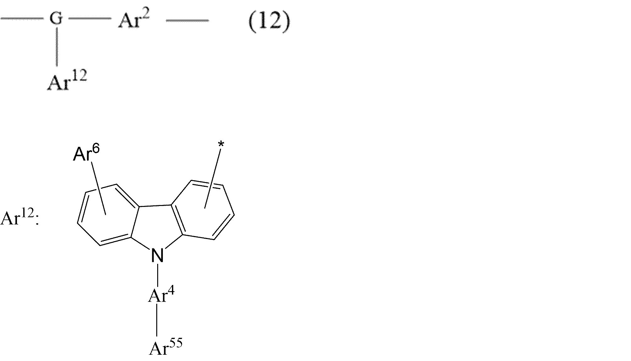
G、Ar2、Ar4、及びAr6は、式(1)におけるG、Ar2、及びAr4とそれぞれ同様であり、
Ar55は、下記のスキーム2に示すa-1~a-4、b-1~b-9、c-1~c-5、d-1~d-16、及びe1~e4から選択されるいずれかの構造を表す。
なお、Ar12中の“-*”が式(12)中Gと結合する部位(結合位置)である。
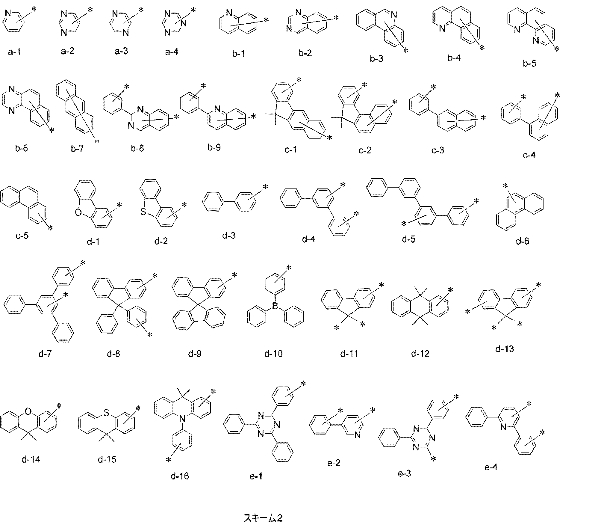

G、Ar2、Ar4、及びAr6は、上述の式(1)におけるG、Ar2、及びAr4とそれぞれ同様であり、
Ar33、及びAr34は、それぞれ独立に、置換基を有していてもよい二価の芳香族炭化水素基、置換基を有していてもよい芳香族複素環基、又は置換基を有していてもよい芳香族炭化水素基若しくは置換基を有していてもよい芳香族複素環基が直接若しくは連結基を介して複数個連結した二価の基を表し、
Ar555は、水素原子、置換基を有していてもよい芳香族炭化水素基、置換基を有していてもよい芳香族複素環基、又は置換基を有していてもよい芳香族炭化水素基若しくは芳香族複素環基が直接若しくは連結基を介して複数個連結した一価の基を表す。
なお、Ar13中の“-*”が式(13)中Gと結合する部位(結合位置)である。
本実施形態の重合体の具体例を以下に示すが、これらに限定されるものではない。なお、化学式中の数字は繰返し単位のモル比を表す。
これらの重合体は、ランダム共重合体、交互共重合体、ブロック共重合体、又はグラフト共重合体等のいずれでもよく、単量体の配列順序は限定されない。

本実施形態の重合体の製造方法は特には制限されない。例えば、Suzuki反応による重合方法、Grignard反応による重合方法、Yamamoto反応による重合方法、Ullmann反応による重合方法、Buchwald-Hartwig反応による重合方法等などによって製造できる。
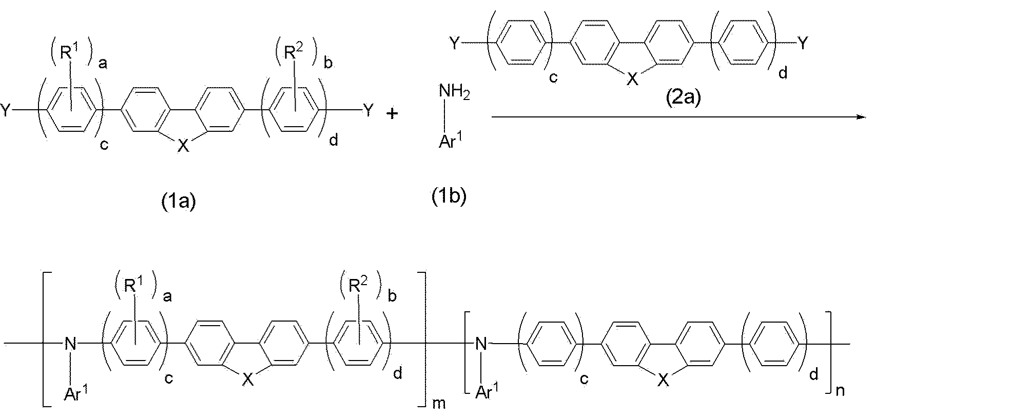
なお、前記の重合方法において、通常、N-アリール結合を形成する反応は、例えば炭酸カリウム、tert-ブトキシナトリウム、トリエチルアミン等の塩基存在下で行う。また、例えば銅やパラジウム錯体等の遷移金属触媒存在下で行うこともできる。
<同一の部分構造>
本発明の第2の要旨の実施形態である有機電界発光素子は、陽極、陰極、及び該陽極と該陰極の間に有機層を有する有機電界発光素子であって、該有機層は、正孔輸送層と、正孔輸送層に隣接する発光層とを有し、正孔輸送層が前記式(1)で表される重合体1又は該重合体1が架橋した重合体を含み、該重合体1又は該重合体1が架橋した重合体と、発光層に含まれる材料の少なくとも一つとが、ともにカルバゾール環を有する下記式(CzP)で表わされる部分構造を有する材料(下記式(CzP)で表わされる部分構造を有する化合物)を含む、有機電界発光素子であることが好ましい。なお、本明細書における「材料」の記載について、「化合物」と置き換えることができる記載は「化合物」と置き換えてもよい。

式(CzP)で表わされる部分構造を有する材料が高分子化合物である場合、高分子化合物に含まれる式(CzP)の数としては、高分子化合物の繰り返し単位中に含まれる式(CzP)の数以上であることが好ましい。繰り返し単位中に式(CzP)が二つ存在する場合、高分子化合物に含まれる式(CzP)の数は高分子化合物の繰り返し単位の2倍となる。高分子化合物が複数の繰り返し単位を有する場合、少なくとも一つの繰り返し単位が式(CzP)を有していればよい。式(CzP)は置換基を有していてもよい。
次に、本実施形態の素子に含まれる式(CzP)で表わされる部分構造を有する材料が、低分子化合物である場合について説明する。発光層に用いられる発光材料またはホスト材料として用いられる低分子化合物に式(CzP)が用いることができ、ホスト材料の場合は、例えば以下である。

置換基としては、前述の置換基群Zから選ばれる基を用いることができる。
正孔輸送層と正孔輸送層に隣接する発光層との間の電荷の授受は主に正孔輸送層を形成する材料と発光層中のホスト材料との間で行われるため、発光層に用いられるホスト材料が、式(CzP)、及び/又は式(CzP-2)を有することで特に界面での正孔輸送性を向上することができる。
電荷輸送性に優れる骨格としては、具体的には、芳香族構造、芳香族アミン構造、トリアリールアミン構造、ジベンゾフラン構造、ナフタレン構造、フェナントレン構造、フタロシアニン構造、ポルフィリン構造、チオフェン構造、ベンジルフェニル構造、フルオレン構造、キナクリドン構造、トリフェニレン構造、カルバゾール構造、ピレン構造、アントラセン構造、フェナントロリン構造、キノリン構造、ピリジン構造、ピリミジン構造、トリアジン構造、オキサジアゾール構造又はイミダゾール構造等を有するものが挙げられる。
正孔輸送性材料は、正孔輸送性に優れた構造を有する化合物であり、前記電荷輸送性に優れた骨格としては、カルバゾール構造、ジベンゾフラン構造、トリアリールアミン構造、ナフタレン構造、フェナントレン構造又はピレン構造を有するものを用いることができ、この中でもカルバゾール構造、ジベンゾフラン構造又はトリアリールアミン構造を有するものが特に好ましい。
ホスト材料の骨格と式(CzP-2)との間に用いられる構造としては、例えばアリーレン基を用いることができる。アリーレン基としては、例えば、フェニレン、ビフェニレン、トリフェニレンが挙げられ、分岐を有していてもよい。
発光層に含まれる、式(CzP)で表される部分構造を有する化合物、特に低分子化合物は、下記式(14)、下記式(15)、又は下記式(16)のいずれかで表される化合物であることが好ましい。
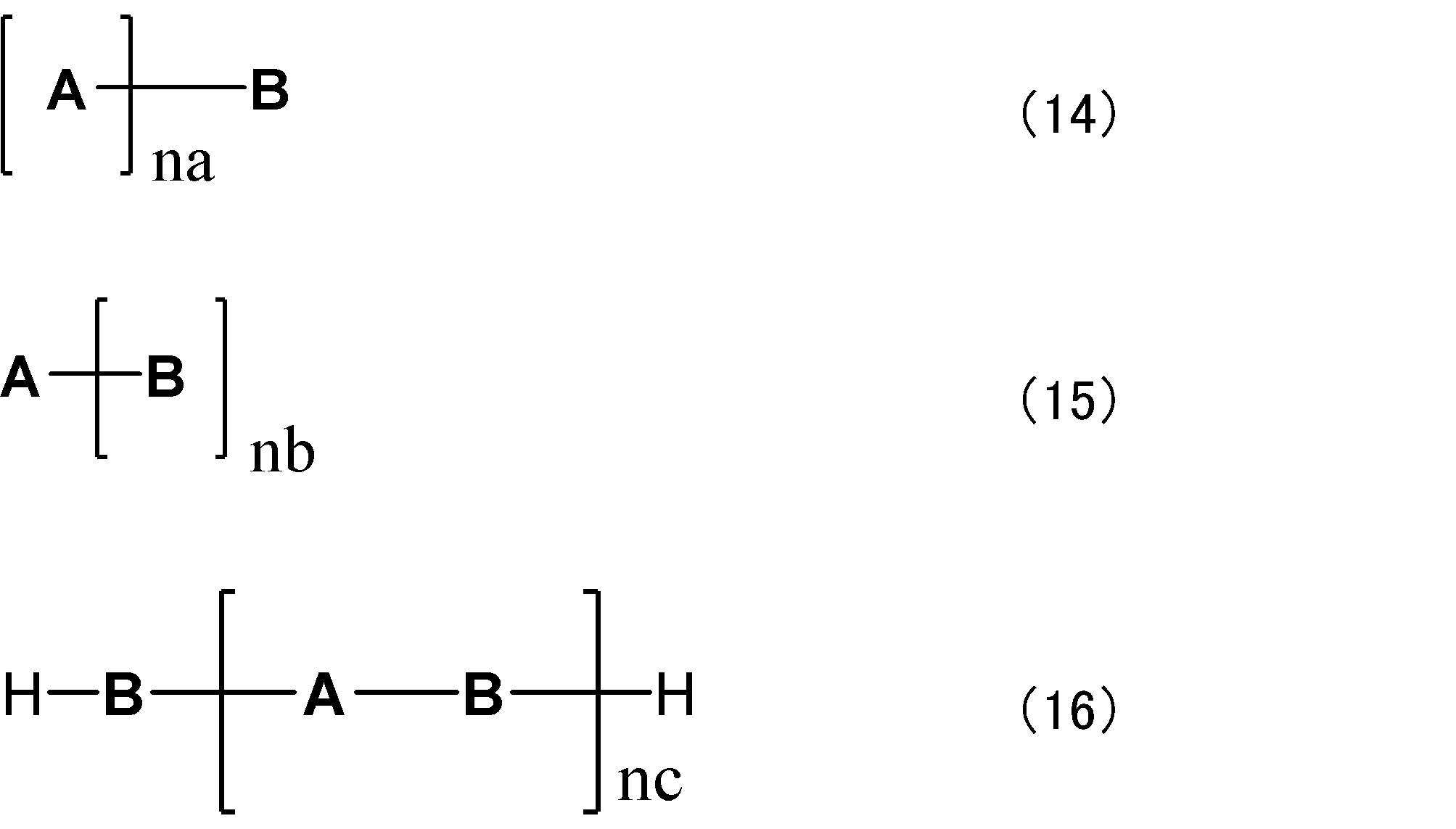
Aは前記式(CzP)で表される部分構造であり、置換基を有していてもよい。
Bは単結合または任意の部分構造を表す。
Aが複数存在する場合、同一であっても互いに異なっていてもよい。
Bが複数存在する場合、同一であっても互いに異なっていてもよい。
na、nb及びncはそれぞれ独立に1以上、5以下の整数を表し、
前記式(14)~(16)で表される化合物の分子量は5,000以下である。
Aにおける有していてもよい置換基は、前記置換基群Zから選ばれることが好ましく、好ましい基およびさらに有してよい置換基も同様である。
前記式(14)~(16)におけるBは、特に限定されないが、好ましくは置換基を有していてもよい機能性基、置換基を有していてもよい芳香族炭化水素基、置換基を有していてもよい芳香族複素環基、又は置換基を有していてもよい芳香族炭化水素基および置換基を有していてもよい芳香族複素環基から選ばれる2以上の基が複数個連結した構造を表す。これらの有していてもよい置換基としては、上述した置換基群Zのいずれかまたは、これらの組み合わせを用いることができる。
機能性基としては、正孔輸送性を有する構造、電子輸送性を有する構造、電荷輸送を抑制する構造、有機溶剤への可溶性を付与する構造、結晶化を阻害しアモルファス性を向上させる構造、又は発光性を有する構造が好ましい。
芳香族炭化水素基、芳香族複素環基、芳香族炭化水素基および芳香族複素環基から選ばれる2以上の基が複数個連結した一価の基としては、上述の式(1)におけるAr2と同様の構造が好ましい。複数個連結する場合も同様に、2~10連結することが好ましく、2~5連結することがさらに好ましい。
Bが結合するAの位置としては、カルバゾール環の炭素原子またはカルバゾール環の窒素原子に結合しているベンゼン環であることが好ましく、少なくとも一つのBが部分構造Aにおけるカルバゾール環のNに結合しているベンゼン環であることがより好ましい。
式(CzP)で表される部分構造を有する低分子化合物は、好ましくは発光層中の電荷輸送材料である。
発光層に含まれる、式(CzP)で表される部分構造を有する低分子化合物は、好ましくは前記式(14)又は前記式(16)である。
さらに、前記式(14)で表される化合物は、下記式(17)で表される化合物であることが好ましく、また、式(16)で表される化合物は、後述の式(19)で表される化合物であることが好ましい。
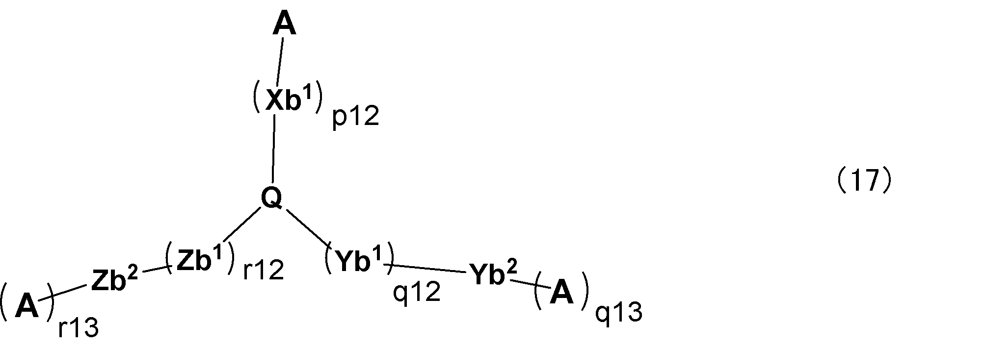
Qは、窒素原子または、下記構造式(18-1)、(18-2)及び(18-3)で表される3価の置換基のいずれかを表し、
Xb1、Yb1、及びZb1は、各々独立に、置換基を有していてもよい炭素数6~30の二価の炭化水素芳香環基、又は置換基を有していてもよい炭素数3~30の二価の複素芳香環基を表し、Xb1、Yb1、及びZb1のそれぞれは複数存在する場合は同一であっても異なっていてもよく、
Aは前記式(CzP)で表される部分構造であり、置換基を有していてもよく、かつ、複数存在するAは互いに同一であっても異なっていてもよく、
p12、q12、及びr12は、各々独立に、0以上6以下の整数を表し、
q13、r13は、各々独立に、0または1を表し、
q13が0の場合のYb2及び、r13が0の場合のZb2は各々独立に、水素原子、置換基を有していてもよい炭素数6~30の一価の炭化水素芳香環基、又は置換基を有していてもよい炭素数3~30の一価の複素芳香環基を表し、
q13が1の場合のYb2は直接結合であり、
r13が1の場合のZb2は直接結合である。
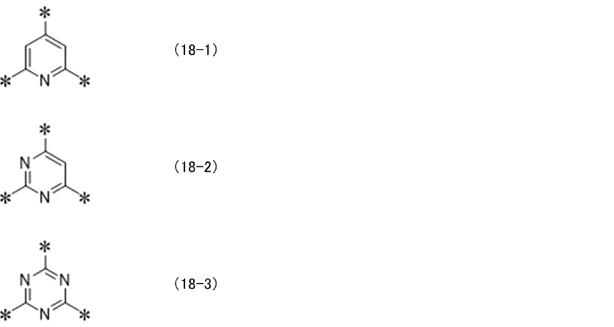

Xc1及びYc1は、各々独立に、置換基を有していてもよい炭素数6~30の二価の炭化水素芳香環基、又は置換基を有していてもよい炭素数3~30の二価の複素芳香環基を表し、
Xc2及びYc2は、各々独立に、水素原子、置換基を有していてもよい一価の炭素数6~30の炭化水素芳香環基、又は置換基を有していてもよい炭素数3~30の一価の複素芳香環基を表し、
Xc1及びYc1のそれぞれは、複数存在する場合は同一であっても異なっていてもよく、
Aは前記式(CzP)で表される部分構造であり、置換基を有していてもよく、
s11及びt11は、各々独立に、0以上6以下の整数を表し、
ncは、1以上、5以下の整数を表す。
中でも好ましくはチオフェン環、ピロール環、イミダゾール環、ピリジン環、ピリミジン環、トリアジン環、キノリン環、キナゾリン環、カルバゾール環、ジベンゾフラン環、ジベンゾチオフェン環、インドロカルバゾール環、フェナントロリン環、又はインドロカルバゾール環であり、
さらに好ましくは、ピリジン環、ピリミジン環、トリアジン環、キノリン環、キナゾリン環、カルバゾール環、ジベンゾフラン環、ジベンゾチオフェン環、又はインドロカルバゾール環であり、
さらに好ましくはカルバゾール環、ジベンゾフラン環、ジベンゾチオフェン環、又はインドロカルバゾール環である。
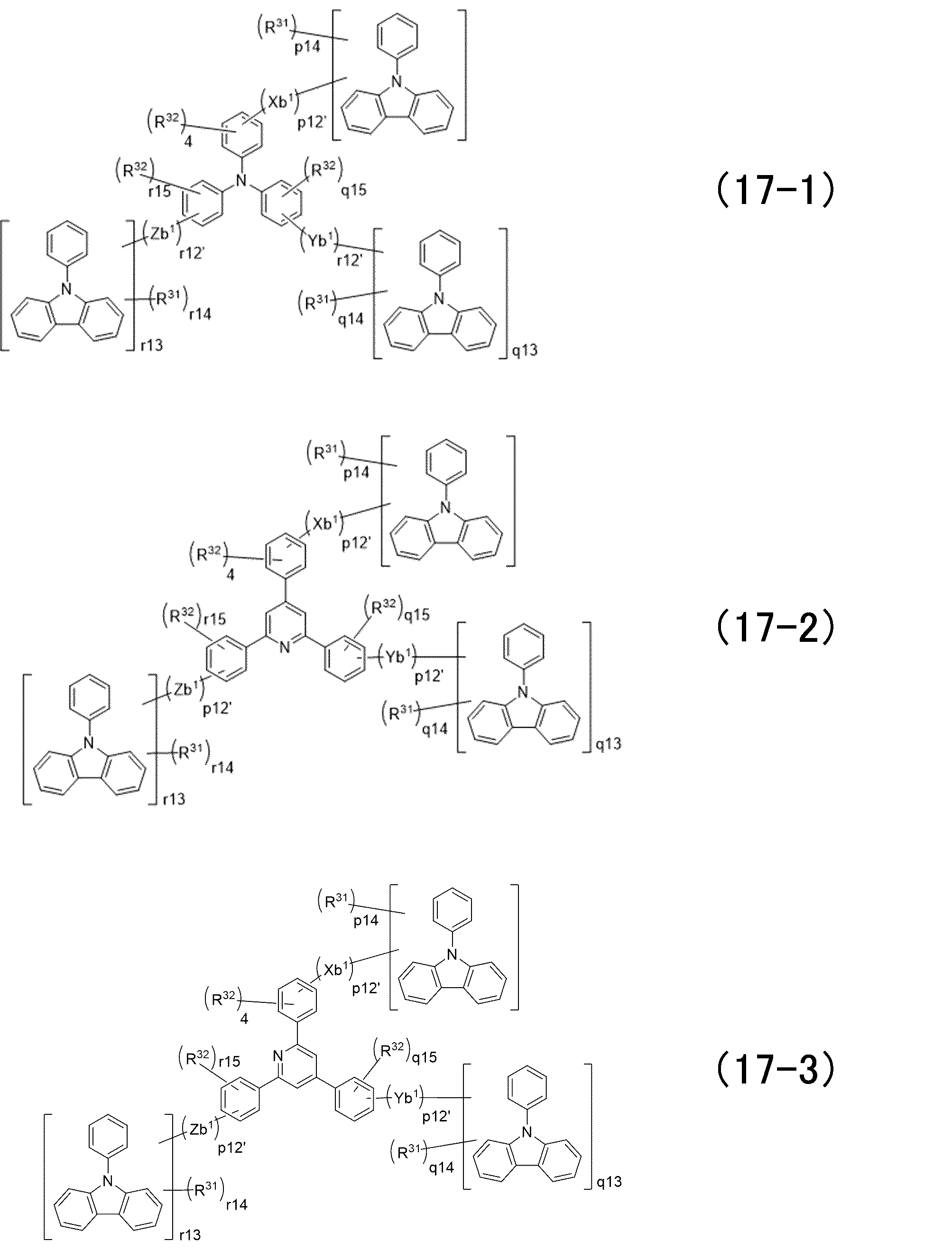

p12’は、1以上5以下の整数を表し、
q12’及びr12’は、それぞれ独立に、0以上5以下の整数を表し、
p14は12であり、
q14はq13が1の場合は12であり、q13が0の場合は存在せず、
r14はr13が1の場合は12であり、r13が0の場合は存在せず、
q15及びr15は、それぞれ独立に、4又は5であり、
R31及びR32は、それぞれ独立に、水素原子または置換基であり、
Xb1、Yb1、Zb1、q13、r13は、それぞれ前記式(17)と同じである。
置換基であるR31としては、水素原子、又は前記Aが有してよい置換基と同様であり、好ましい置換基としても同様であり、さらに有していてもよい置換基も同様である。
置換基であるR32としては、水素原子、又は前記式(1)で表される重合体における前記置換基群Zに挙げられる置換基または前記架橋性基と同様であり、好ましい置換基及び、さらに有していてもよい置換基も同様である。
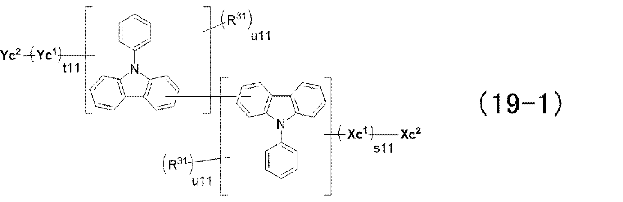
R31は、水素原子または置換基であり、
u11は、11を表し、
Xc1、Yc1、Xc1、Yc1、t11、及びs11は、それぞれ前記式(19)と同じである。
置換基である場合のR31は、上述の式(1)で表される重合体における前記置換基群Zに挙げられる置換基または前記架橋性基と同様であり、好ましい置換基及び、さらに有していてもよい置換基も同様である。
上述の式(CzP-2)を有するホスト材料としては例えば以下の化合物が挙げられる。
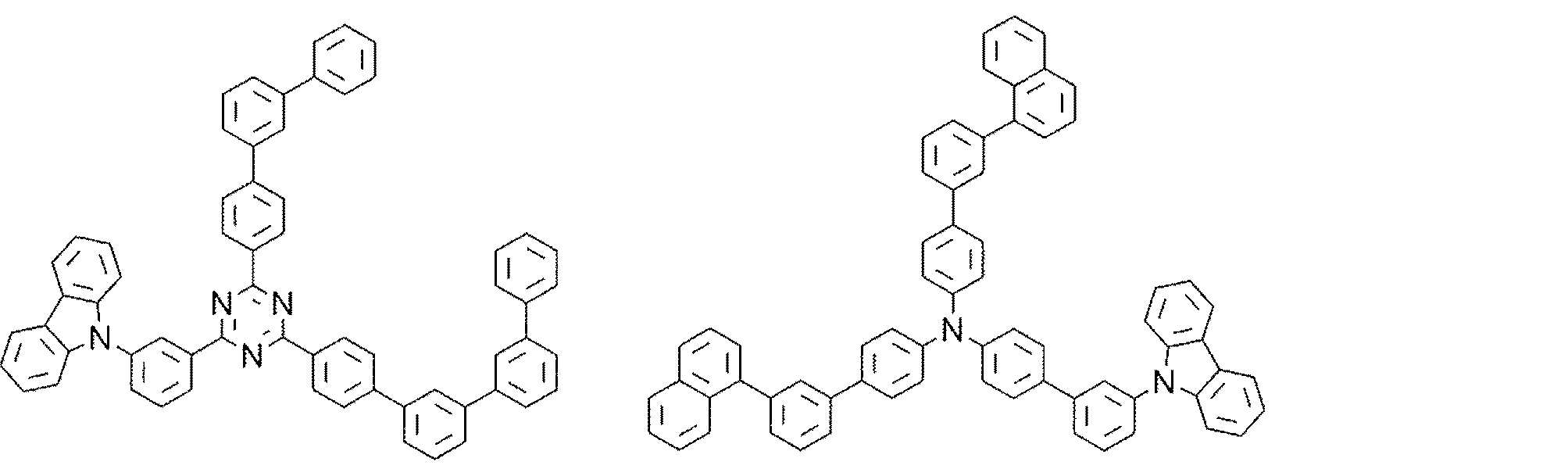
本発明の第3の要旨の実施形態は、基板上に、陽極、陰極、及び該陽極と該陰極の間に有機層を有する有機電界発光素子であって、該有機層は、正孔輸送層と、正孔輸送層に隣接する発光層とを有し、正孔輸送層に含まれる材料と発光層に含まれる材料とがともにカルバゾール環を有する下記式(CzP)で表わされる部分構造を有する材料を含む、有機電界発光素子である。

式(CzP)で表わされる部分構造を有する材料が高分子化合物である場合、高分子化合物に含まれる式(CzP)の数としては、高分子化合物の繰り返し単位中に含まれる式(CzP)の数以上であることが好ましい。繰り返し単位中に式(CzP)が二つ存在する場合、高分子化合物に含まれる式(CzP)の数は高分子化合物の繰り返し単位×2となる。高分子化合物が複数の繰り返し単位を有する場合、少なくとも一つの繰り返し単位が式(CzP)を有していればよい。式(CzP)は置換基を有していてもよい。
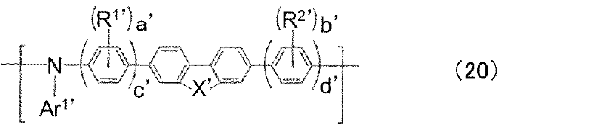
Ar1’は、置換基を有していてもよい芳香族炭化水素基又は置換基を有していてもよい芳香族複素環基を表し、Ar1’の少なくとも一つは下記式(21)で表され、
Xは、-C(R3’)(R4’)-、-N(R5’)-または-C(R11’)(R12’)-C(R13’)、(R14’)-を表し、
R1’及びR2’は、各々独立に、置換基を有していてもよいアルキル基を表し、
R3’~R5’及びR11’~R14’は、各々独立に、置換基を有していてもよいアルキル基、置換基を有していてもよいアラルキル基、又は置換基を有していてもよい芳香族炭化水素基を表し、
a、bは、各々独立に、0~4の整数であり、a+bは1以上であり、
cは1~3の整数であり、
dは0~4の整数であり、
R1’及びR2’が該繰り返し単位中に複数ある場合は、R1’及びR2’は同一であっても異なっていてもよい。

Ar11’及びAr12’は、それぞれ独立に、置換基を有していてもよい二価の芳香族炭化水素基又は芳香族複素環基を表し、
Ar13’~Ar15’は、それぞれ独立に、水素原子又は置換基を表す。
*は結合位置を表す。
Ar11’~Ar15’の少なくとも一つは式(21)の他に式(CzP)として、下記式(CzP-1)を有するものであってもよい。

置換基としては、例えば、上述のAr13’~Ar15’と同様のものを用いることができる。
上記式(20)で表される繰り返し単位中のR1’及びR2’は、各々独立に、置換基を有していてもよいアルキル基を表す。アルキル基の炭素数は特に限定されないが、重合体の溶解性を維持するために、炭素数が1以上、6以下が好ましく、3以下がより好ましく、メチル基又はエチル基であることがさらに好ましい。また、該アルキル基は、直鎖、分岐又は環状の各構造であってもよい。
R3’~R5’及びR11’~R14は、各々独立に、置換基を有していてもよいアルキル基、置換基を有していてもよいアラルキル基、又は置換基を有していてもよい芳香族炭化水素基を表す。
具体的には、メチル基、エチル基、n-プロピル基、i-プロピル基、n-ブチル基、i-ブチル基、sec-ブチル基、tert-ブチル基、n-ヘキシル基、n-オクチル基、シクロヘキシル基、ドデシル基等が挙げられる。
具体的には、1,1-ジメチル-1-フェニルメチル基、1,1-ジ(n-ブチル)-1-フェニルメチル基、1,1-ジ(n-ヘキシル)-1-フェニルメチル基、1,1-ジ(n-オクチル)-1-フェニルメチル基、フェニルメチル基、フェニルエチル基、3-フェニル-1-プロピル基、4-フェニル-1-n-ブチル基、1-メチル-1-フェニルエチル基、5-フェニル-1-n-プロピル基、6-フェニル-1-n-ヘキシル基、6-ナフチル-1-n-ヘキシル基、7-フェニル-1-n-ヘプチル基、8-フェニル-1-n-オクチル基、4-フェニルシクロヘキシル基等が挙げられる。
具体的には、ベンゼン環、ナフタレン環、アントラセン環、フェナントレン環、ペリレン環、テトラセン環、ピレン環、ベンズピレン環、クリセン環、トリフェニレン環、アセナフテン環、フルオランテン環、フルオレン環等の、6員環の単環又は2~5縮合環の一価の基、またはこれらが複数連結した基等が挙げられる。
溶解性を向上しつつ電荷輸送性に優れる点では、R3’及びR4’は炭素数3以上6以下のアルキル基又は炭素数9以上40以下のアラルキル基が好ましい。
前記R1’及びR2’のアルキル基、R3’~R5’及びR11’~R14’のアルキル基、アラルキル基及び芳香族炭化水素基は、低電圧化の観点からは、置換基を有さないことが最も好ましい。
前記式(20)で表される繰り返し単位中において、a’及びb’は各々独立に、0~4の整数であり、a’+b’は1以上である。さらに、a’及びb’は、各々2以下であることが好ましく、a’とb’の両方が1であることがさらに好ましい。
前記式(20)で表される繰り返し単位中において、c’は1~3の整数であり、d’は0~4の整数である。c’及びd’は、各々2以下であることが好ましく、c’とd’は等しいことがさらに好ましく、c’とd’の両方が1であるか、又はc’とd’の両方が2であることがさらに好ましい。
ここで、「R1’とR2’とが互いに対称な位置に結合する」とは、式(20)におけるフルオレン環またはカルバゾール環に対して、R1’とR2’の結合位置が対称であることをいう。例えば、式(20)に含まれる以下式(20a)において、R1a’とR2a’とが対象の位置、R1b’とR2b’とが対象の位置と言える。また、このとき、主鎖を軸とする180度回転は同一構造とみなす。例えば、以下、式(20a)と式(20b)とは同一構造とみなすことができる。
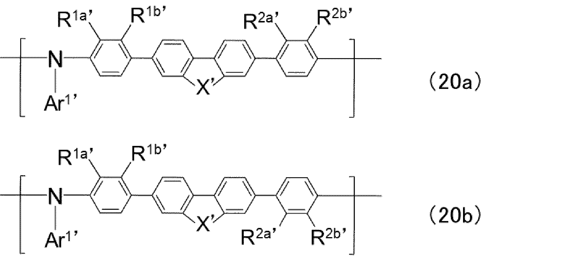
前記式(20)で表される繰り返し単位中において、Ar1’は、置換基を有していてもよい芳香族炭化水素基、置換基を有していてもよい芳香族複素環基又は下記式(21)で表される基を表す。
芳香族炭化水素環基としては、炭素数が6以上、60以下が好ましく、具体的には、ベンゼン環、ナフタレン環、アントラセン環、フェナントレン環、ペリレン環、テトラセン環、ピレン環、ベンズピレン環、クリセン環、トリフェニレン環、アセナフテン環、フルオランテン環、フルオレン環等の、6員環の単環又は2~5縮合環の一価の基またはこれらが複数連結した基が挙げられる。
前記式(20)で表される繰り返し単位におけるAr1’の少なくとも一つは、下記式(21)で表される基である。
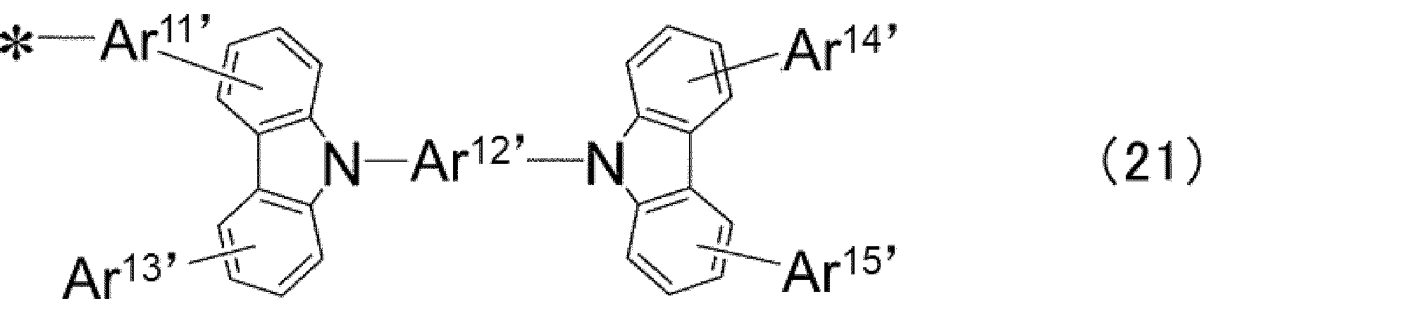
Ar11’及びAr12’は、それぞれ独立に、置換基を有していてもよい二価の芳香族炭化水素基又は芳香族複素環基を表し、
Ar13’~Ar15’は、それぞれ独立に、水素原子又は置換基を表す。
置換基としては、例えば以下置換基群Z’から選択される置換基を用いることができる。置換基群Z’として、以下の構造が挙げられる。
例えば、ビニル基等の、炭素数が通常2以上であり、通常24以下、好ましくは12以下であるアルケニル基;
例えば、エチニル基等の、炭素数が通常2以上であり、通常24以下、好ましくは12以下であるアルキニル基;
例えば、メトキシ基、エトキシ基等の、炭素数が通常1以上であり、通常24以下、好ましくは12以下であるアルコキシ基;
例えば、フェノキシ基、ナフトキシ基、ピリジルオキシ基等の、炭素数が通常4以上、好ましくは5以上であり、通常36以下、好ましくは24であるアリールオキシ基;
例えば、メトキシカルボニル基、エトキシカルボニル基等の、炭素数が通常2以上であり、通常24以下、好ましくは12以下であるアルコキシカルボニル基;
例えば、ジメチルアミノ基、ジエチルアミノ基等の、炭素数が通常2以上であり、通常24以下、好ましくは12以下であるジアルキルアミノ基;
例えば、ジフェニルアミノ基、ジトリルアミノ基、N-カルバゾリル基等の、炭素数が通常10以上、好ましくは12以上であり、通常36以下、好ましくは24以下のジアリールアミノ基;
例えば、フェニルメチルアミノ基等の、炭素数が通常7であり、通常36以下、好ましくは24以下であるアリールアルキルアミノ基;
例えば、アセチル基、ベンゾイル基等の、炭素数が通常2であり、通常24以下、好ましくは12であるアシル基;
例えば、フッ素原子、塩素原子等のハロゲン原子;
例えば、トリフルオロメチル基等の、炭素数が通常1以上であり、通常12以下、好ましくは6以下のハロアルキル基;
例えば、メチルチオ基、エチルチオ基等の、炭素数が通常1以上であり、通常24以下、好ましくは12以下のアルキルチオ基;
例えば、フェニルチオ基、ナフチルチオ基、ピリジルチオ基等の、炭素数が通常4以上、好ましくは5以上であり、通常36以下、好ましくは24以下であるアリールチオ基;
例えば、トリメチルシリル基、トリフェニルシリル基等の、炭素数が通常2以上、好ましくは3以上であり、通常36以下、好ましくは24以下であるシリル基;
例えば、トリメチルシロキシ基、トリフェニルシロキシ基等の、炭素数が通常2以上、好ましくは3以上であり、通常36以下、好ましくは24以下であるシロキシ基;
シアノ基;
例えば、フェニル基、ナフチル基等の、炭素数が通常6以上であり、通常36以下、好ましくは24以下である芳香族炭化水素環基;
例えば、チエニル基、ピリジル基等の、炭素数が通常3以上、好ましくは4以上であり、通常36以下、好ましくは24以下である芳香族複素環基。
また、上記置換基群Z’の各置換基は更に置換基を有していてもよい。それら置換基としては、上記置換基(置換基群Z’)と同じのもの又は後述の架橋性基が挙げられる。好ましくは、更なる置換基は有さないか、炭素数6以下のアルキル基、炭素数6以下のアルコキシ基、フェニル基又は後述の架橋性基である。電荷輸送性の観点からは、さらなる置換基を有さないことがより好ましい。
Ar13’~Ar15’は、各々独立に、水素原子または置換基を表す。Ar13’~Ar15’が置換基である場合、特に限定はされないが、好ましくは置換基を有していてもよい芳香族炭化水素基又は置換基を有していてもよい芳香族複素環基である。好ましい構造としては、前記Ar1’で挙げた基と同様である。
Ar13’~Ar15’は、合成のし易さ及び電荷輸送性の観点からは、水素原子であることが好ましい。
Ar13’~Ar15’は、耐久性向上及び電荷輸送性の観点からは、置換基を有していてもよい芳香族炭化水素基又は置換基を有していてもよい芳香族複素環基であることが好ましく、置換基を有していてもよい芳香族炭化水素基であることがさらに好ましい。
また、不溶化の観点からは、置換基として、少なくとも一つの後述の架橋性基を含む式(21)で表される基を含むことが好ましい。
一方、成膜後の未架橋残基による発光層への悪影響が無い観点からは、置換基として架橋基を含まないことが好ましい。
Ar12’は、置換基を有していてもよい二価の芳香族炭化水素基、又は、置換基を有していてもよい二価の芳香族炭化水素基と置換基を有していてもよい二価の芳香族複素環基とが任意に連結した二価の基であって、式(21)を構成する2つのカルバゾール環のうち少なくとも一方のカルバゾール環のNに結合する構造がフェニレン基である。
また、芳香族複素環基を含む場合、電子吸引性が向上してLUMOが分布しやすいため、電子や励起子に弱い主鎖の窒素原子周辺にLUMOが広がりにくく、耐久性が向上すると考えられる。
Ar11’は、式(20)における主鎖のアミンの窒素原子と連結する二価の基である。Ar11’は特に限定されないが、置換基を有していてもよい二価の芳香族炭化水素基又は置換基を有していてもよい二価の芳香族複素環基が好ましい。
Ar11’の芳香族炭化水素基としては、炭素数が6以上、60以下が好ましく、更に好ましくは炭素数10以上50以下であり、特に好ましくは炭素数12以上40以下である。具体的には、ベンゼン環、ナフタレン環、アントラセン環、フェナントレン環、ペリレン環、テトラセン環、ピレン環、ベンズピレン環、クリセン環、トリフェニレン環、アセナフテン環、フルオランテン環、フルオレン環等の、6員環の単環又は2~5縮合環の二価の基またはこれらが複数連結した基が挙げられる。
これら二価の芳香族炭化水素基または二価の芳香族複素環基が複数連結する場合、好ましくは複数連結した二価の芳香族炭化水素基が共役しないように結合した基である。具体的には、1,3フェニレン基、又は置換基を有し置換基の立体効果によって捻じれ構造となる基を含むことが好ましい。このような連結基を含むことにより、Ar12’上に分布するLUMOが主鎖に広がりにくくなり、電子や励起子に弱い主鎖の窒素原子周辺にLUMOが分布しにくく、耐久性が向上すると考えられる。
前記式(20)で表される繰り返し単位は、下記式(20-I)内のいずれかで示される繰り返し単位であることが最も好ましい。

本実施形態において、末端基とは、重合体の重合終了時に用いたエンドキャップ剤によって形成された、重合体の末端部の構造のことを指す。式(20)で表される繰り返し単位を有する重合体の末端基は炭化水素基であることが好ましい。炭化水素基としては、電荷輸送性の観点から、炭素数1以上60以下が好ましく、1以上40以下がより好ましく、1以上30以下がさらに好ましい。
例えば、メチル基、エチル基、n-プロピル基、i-プロピル基、n-ブチル基、i-ブチル基、sec-ブチル基、tert-ブチル基、n-ヘキシル基、シクロヘキシル基、ドデシル基等の、炭素数が通常1以上であり、好ましくは4以上であり、通常24以下、好ましくは12以下である、直鎖、分岐、又は環状のアルキル基;
例えば、ビニル基等の、炭素数が通常2以上であり、通常24以下、好ましくは12以下であるアルケニル基;
例えば、エチニル基等の、炭素数が通常2以上であり、通常24以下、好ましくは12以下であるアルキニル基;
例えば、フェニル基、ナフチル基等の、炭素数が通常6以上であり、通常36以下、好ましくは24以下である芳香族炭化水素環基;
が挙げられる。
好ましくは、電荷輸送性および耐久性の観点から、アルキル基又は芳香族炭化水素環基であり、更に好ましくは芳香族炭化水素環基である。
上記式(20)で表される繰り返し単位を有する重合体は、上記式(20)で表される繰り返し単位とは別の繰り返し単位を、さらに含んでいてもよい。
別の繰り返し単位としては、電荷輸送性及び耐久性の点で、下記式(22)で表される繰り返し単位が好ましい。なお、ここで、下記式(22)で表される繰り返し単位は、上記式(20)の繰り返し単位中の一部の構造部分と一致しうるが、ここでは、あくまでも、式(20)で表される繰り返し単位以外の構造であることを意味する。

Ar3’は、置換基を有していてもよい芳香族炭化水素基又は芳香族複素環基を表し、
Ar4’は、置換基を有していてもよい二価の芳香族炭化水素基、二価の芳香族複素環基、又は該芳香族炭化水素基及び芳香族複素環基が直接若しくは連結基を介して複数個連結した二価の基を表す。
Ar3’及びAr4’における芳香族炭化水素基及び芳香族炭化水素環基としては、Ar3’は式(20)のAr1’と同様の基、Ar4’は式(20)におけるAr1’と同様の基であって二価である基を表す。また、有していてもよい置換基は前記置換基群Z’または後述の架橋性基と同様の基が好ましく、さらに有していてよい置換基も前記置換基群Z’と同様と同様である。
電荷輸送性、耐久性の他、陽極側からの正孔注入に優れる点で、上記式(22)中のAr4’が、下記式(23)で表される基であることがさらに好ましい。

k’及びn’は、各々独立に、0~3の整数を表し、k’+n’は1以上であり、
m’は、0又は1の整数を表す。
X’は、式(20)と同様であり、*1、*2は隣接する構造との結合位置を表す。
式(23)において、電子耐久性に優れる点で、k’+n’は2が好ましく、3が更に好ましい。
重合体の溶媒への溶解性が優れる点で、m’は1であることがより好ましい。
前記式(22)において、芳香族炭化水素基及び芳香族複素環基が、連結基を介して複数個連結したものである場合の連結基としては、具体的には、例えば、-O-基、-C(=O)-基、及び水素原子が置換されていてもよい-CH2-基から選ばれる基を任意の順番で1~30個、好ましくは1~5個、更に好ましくは1~3個連結してなる二価の連結基等が挙げられる。

p’は1~10の整数を表し、
R8’及びR9’は、各々独立して、水素原子又は置換基を有していてもよいアルキル基、芳香族炭化水素基、又は芳香族複素環基を表す。
R8’及びR9’が複数個存在する場合、同じであっても異なっていてもよい。
R8’及びR9’におけるアルキル基は、前記R1’で挙げたアルキル基と同様の基であり、芳香族炭化水素基及び芳香族複素環基は、前記Ar1’で挙げた芳香族炭化水素基及び芳香族複素環基と同様の基である。また、これらの基が有していてもよい置換基は、前記置換基群Z’又は後述の架橋性基と同様の基が好ましく、さらに有していてよい置換基も前記置換基群Z’と同様である。

Ar2’は、置換基を有していてもよい芳香族炭化水素基又は芳香族複素環基を表し、
R17’~R19’は、各々独立に、置換基を有していてもよいアルキル基、アルコキシ基、アラルキル基、芳香族炭化水素基又は芳香族複素環基を表し、
f’、g’、h’は、各々独立して、0~4の整数を表し、f’+g’+h’は1以上であり、
e’は0~3の整数を表す。
Ar2’及びR17’~R19’における芳香族炭化水素基、芳香族複素環基は、各々独立に、前記Ar1’で挙げたものと同様の基である、また、これらの基が有していてもよい置換基は、前記置換基群Z’又は後述の架橋性基と同様の基が好ましい。
R17’~R19’におけるアルキル基及びアラルキル基は、前記R7’で挙げたものと同様の基が好ましく、さらに有していてもよい置換基も前記R7’と同様の基が好ましい。
R17’~R19’におけるアルコキシ基は、前記置換基群Z’で挙げたアルコキシ基が好ましく、さらに有していてもよい置換基も前記置換基群Z’と同様である。
f’、g’、h’は、各々独立して、0~4の整数を表し、f’+g’+h’は1以上である。
f’+h’は1以上であることが好ましく、
f’+h’は1以上、且つ、f’、g’及びh’は2以下であることがより好ましく、
f’+h’は1以上、且つ、f’、h’は1以下であることがさらに好ましく、
f’、h’はいずれも1であることが最も好ましい。
f’及びh’がいずれも1である場合、R17’とR19’は互いに対称な位置に結合していることが好ましい。
g’は2であることがより好ましい。
g’が2である場合、2つのR18’は互いにパラ位に結合していることが最も好ましく、
g’が2である場合、2つのR18’は同一であることが最も好ましい。
ここで、R17’とR19’が互いに対称な位置に結合するとは、下記の結合位置のことを言う。ただし、表記上、主鎖を軸とする180度回転は同一構造とみなす。
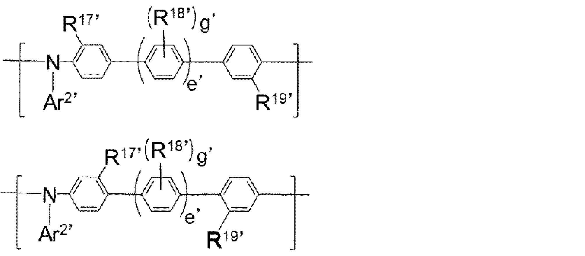

また、前記式(26)で表される繰り返し単位は下記式(27)で示される繰り返し単位であることがさらに好ましい。
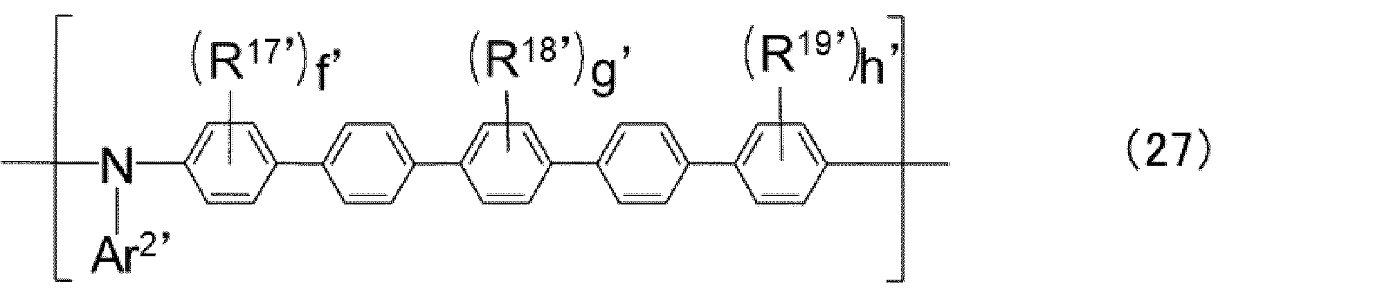
式(20)で表される繰り返し単位を有する重合体において、式(20)で表される繰り返し単位の含有量は特に制限されないが、通常重合体中に10モル%以上含まれ、30モル%以上含まれることが好ましく、40モル%以上含まれることがさらに好ましく、50モル%以上含まれることが特に好ましい。式(20)で表される繰り返し単位を有する重合体は、繰り返し単位が、式(20)で表される繰り返し単位のみから構成されていてもよいが、有機電界発光素子とした場合の諸性能をバランスさせる目的から、式(20)とは別の繰り返し単位を有していてもよく、その場合、重合体中の式(20)で表される繰り返し単位の含有量は、通常、99モル%以下、好ましくは95モル%以下である。
重合体の繰り返し単位の組み合わせは特に限定されないが、式(20)で表される繰り返し単位及び式(22)のAr4が式(23)である繰り返し単位をと含む、下記式(28)で表される繰り返し単位を有することが、電荷輸送性向上および耐久性向上の観点から好ましい。

Ar1’、Ar3’、X’、R1’、R2’、a’、b’、c’、d’、k’、m’及びn’は、式(20)、式(22)及び式(23)におけるものと各々同様である。
好ましい構造、範囲等も、式(20)、式(22)及び式(23)におけるものと同様である。
更に好ましくは、c’=d’=k’=n’及びm’=1である。
AのX’及びBのX’が-C(R3’)(R4’)-であるか、AのX’およびBのX’が-NR5’-であるか、又はAのX’及びBのX’が-C(R11’)(R12’)-C(R13’)(R14’)-であることによって、重合体中に含まれる繰り返しの基本骨格が同じであることから、電荷のトラップとなるような準位が形成されにくく、電荷輸送性に優れ、かつ耐久性に優れると考えらえる。
本実施形態において正孔輸送層に用いることができる重合体3は、側鎖に下記式(30)で表される構造を有するものである。
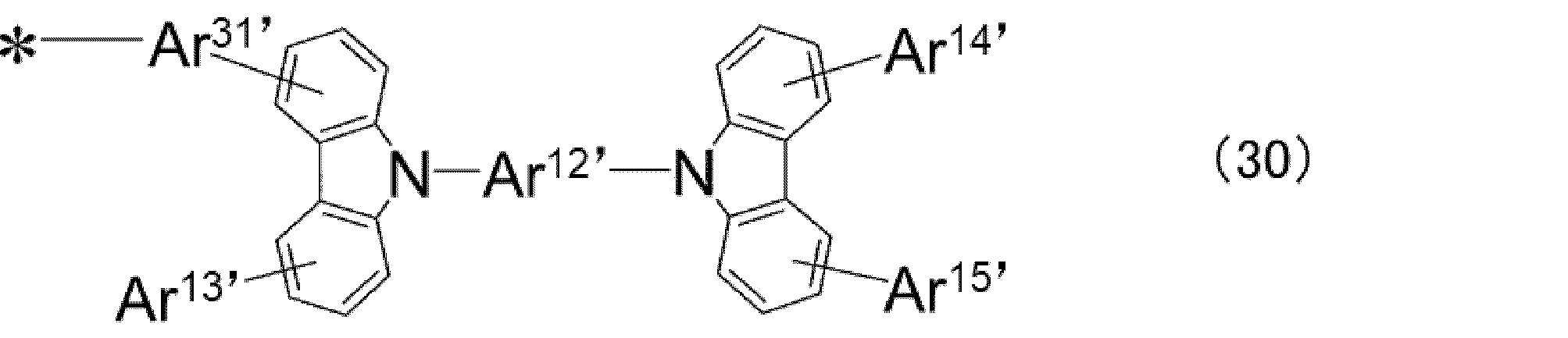
Ar31’は主鎖と連結する二価の基を表し、
Ar12’は、置換基を有していてもよい二価の芳香族炭化水素基又は置換基を有していてもよい二価の芳香族複素環基を表し、
Ar13’~Ar15’は、各々独立に、水素原子または置換基を表す。
*は結合位置を表す。
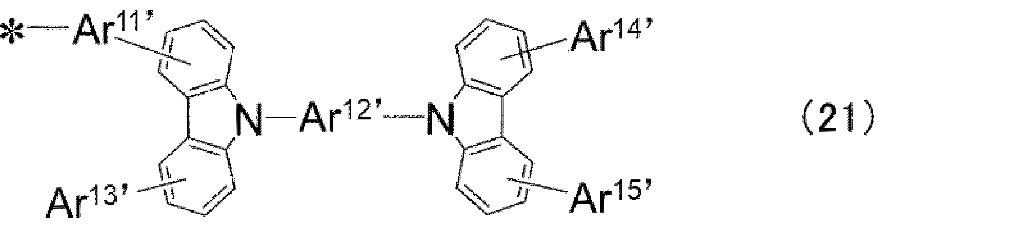
Ar11’及びAr12’は、それぞれ独立に、置換基を有していてもよい二価の芳香族炭化水素基又は芳香族複素環基を表し、
Ar13’~Ar15’は、それぞれ独立に、水素原子又は置換基を表す。
上記側鎖に式(21)で表される構造を有する重合体は、下記式(31)で表される構造を有するものであることが好ましい。
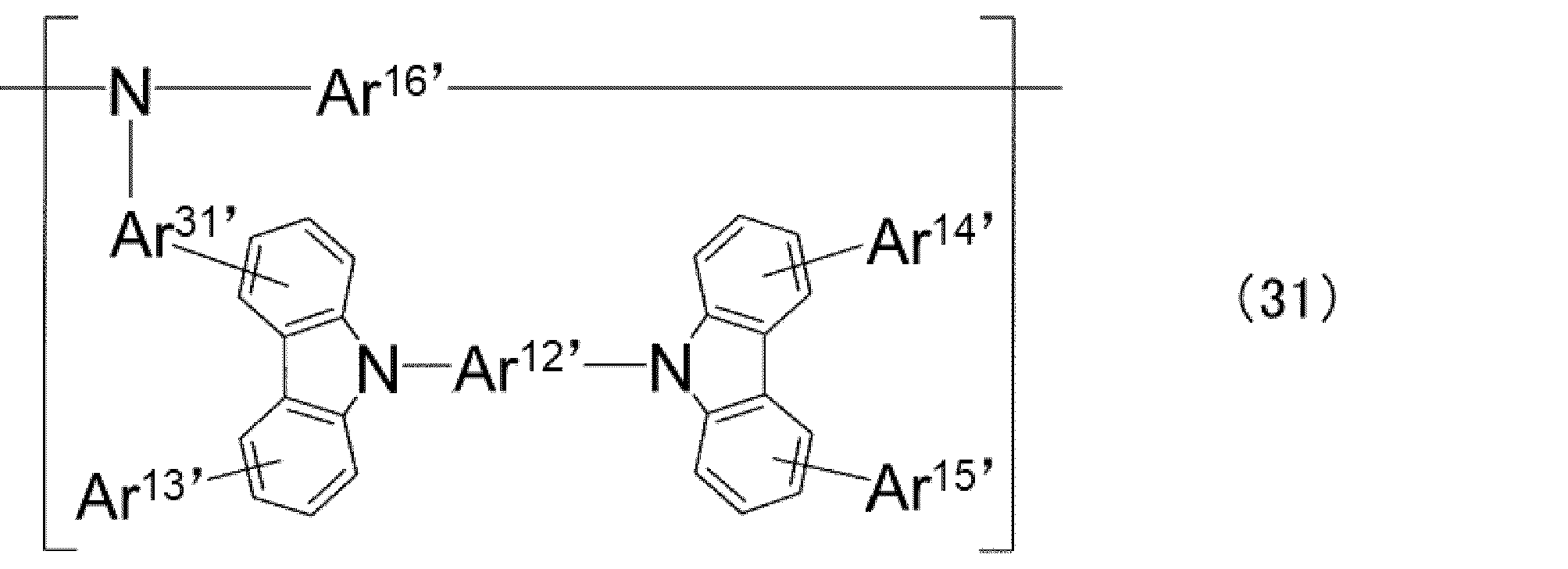
Ar13’~Ar15’、Ar31’は式(21)と同様であり、
Ar16’は、重合体の主鎖を構成する構造を表す。
式(CzP)で表わされる部分構造を有する本実施形態の重合体は、溶媒への可溶性発現のため可溶性基を有することが好ましい。本実施形態における可溶性基は、炭素数3以上24以下、好ましくは炭素数12以下の、直鎖又は分岐のアルキル基またはアルキレン基を有する基である。これらの中でも好ましくは、アルキル基、アルコキシ基、またはアラルキル基であり、例えば、n-プロピル基、2-プロピル基、n-ブチル基、イソブチル基等である。より好ましくはn-ヘキシル基又はn-オクチル基である。可溶性基は置換基を有していてもよい。
式(CzP)で表わされる部分構造を有する本実施形態の重合体が有する可溶性基は、湿式成膜法に利用可能な重合体溶液を得やすくなる点では、多い方が好ましい。一方で、成膜した層の上に湿式成膜法で他の層を形成した際に層が溶媒に溶解してしまうことによる膜厚減少が少ない点では、少ない方が好ましい。
式(CzP)で表わされる部分構造を有する本実施形態の重合体が有する可溶性基の数を、重合体の1gあたりのモル数で表した場合、重合体1gあたり、通常4.0ミリモル以下、好ましくは3.0ミリモル以下、さらに好ましくは2.0ミリモル以下であり、また通常0.1ミリモル以上、好ましくは0.5ミリモル以上である。
ここで、重合体の1gあたりの可溶性基の数は、重合体からその末端基を除いて、合成時の仕込みモノマーのモル比と、構造式から算出することができる。

式(CzP)で表わされる部分構造を有する本実施形態の重合体は、架橋性基を有していてもよい。式(CzP)で表わされる部分構造を有する本実施形態の重合体が有してもよい架橋性基は、式(20)で表される繰り返し単位中に存在していてもよく、式(20)で表される繰り返し単位とは別の繰り返し単位中に存在していてもよい。特に、側鎖であるAr1’に架橋性基を有することが、架橋反応が進行しやすいため好ましい。
架橋性基とは、熱及び/又は活性エネルギー線の照射により、該架橋性基の近傍に位置する他の分子を構成している基と反応して、新規な化学結合を生成する基のことをいう。この場合、反応する基は架橋性基と同一の基でも異なった基でもよい。
架橋性基としては、芳香族環に縮環したシクロブテン環、芳香族環に結合したアルケニル基を含む基が好ましく、更に好ましくは下記架橋性基群T’から選ばれる基である。
架橋性基は、前記各構造が有する置換基にさらに置換していることが好ましい。
架橋性基群T’は、以下に示す構造である。
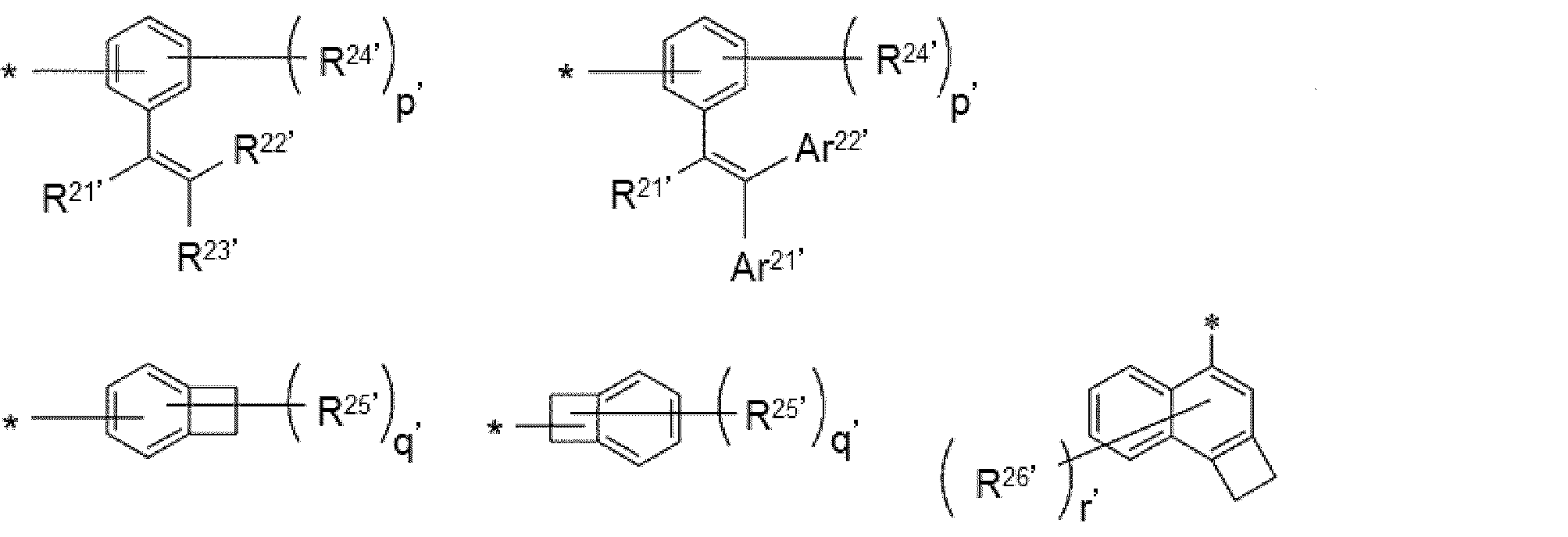
p’が2以上のとき、複数のR24’は同じであっても異なっていてもよく、隣接するR24’同士が結合して環を形成してもよい。
r’が2以上のとき、複数のR26’は同じであっても異なっていてもよい。
Ar21’、Ar22’は置換基を有していてもよい、芳香族炭化水素基又は芳香族複素環基を表す。
Ar22’は、置換基を有していてもよい芳香族炭化水素環基を2以上結合させた基であってもよい。このような基としては、ビフェニレン基、ターフェニレン基等が挙げられ、4,4’-ビフェニレン基が好ましい。
架橋性基として、シンナモイル基などアリールビニルカルボニル基、一価の遊離原子価を有するベンゾシクロブテン環、一価の遊離原子価を有する1,2-ジヒドロシクロブタ〔a〕ナフタレン環等の環化付加反応する基が、素子の電気化学的安定性をさらに向上させる点で好ましい。
式(CzP)で表わされる部分構造を有する本実施形態の重合体が有する架橋性基は、架橋することにより十分に不溶化し、その上に湿式成膜法で他の層を形成しやすくなる点では、多い方が好ましい。一方で、形成された層にクラックが生じ難く、未反応架橋性基が残りにくく、有機電界発光素子が長寿命になりやすい点では、架橋性基は少ないことが好ましい。
また、式(CzP)で表わされる部分構造を有する重合体が有する架橋性基の数は、重合体の分子量1000あたりの数で表すことができる。
架橋性基の数が上記範囲内であると、クラック等が起き難く、平坦な膜が得られ易い。また、架橋密度が適度であるため、架橋反応後の層内に残る未反応の架橋性基が少なく、得られる素子の寿命に影響し難い。
ここで、重合体の分子量1000あたりの架橋性基の数は、重合体からその末端基を除いて、合成時の仕込みモノマーのモル比と、構造式から算出することができる。
例えば、後述の実施例で合成した重合体3の場合で説明すると、重合体3において、末端基を除いた繰り返し単位の分子量は平均868であり、また架橋性基は、1繰り返し単位当たり0.114個である。これを単純比例により計算すると、分子量1000あたりの架橋性基の数は、0.132個と算出される。
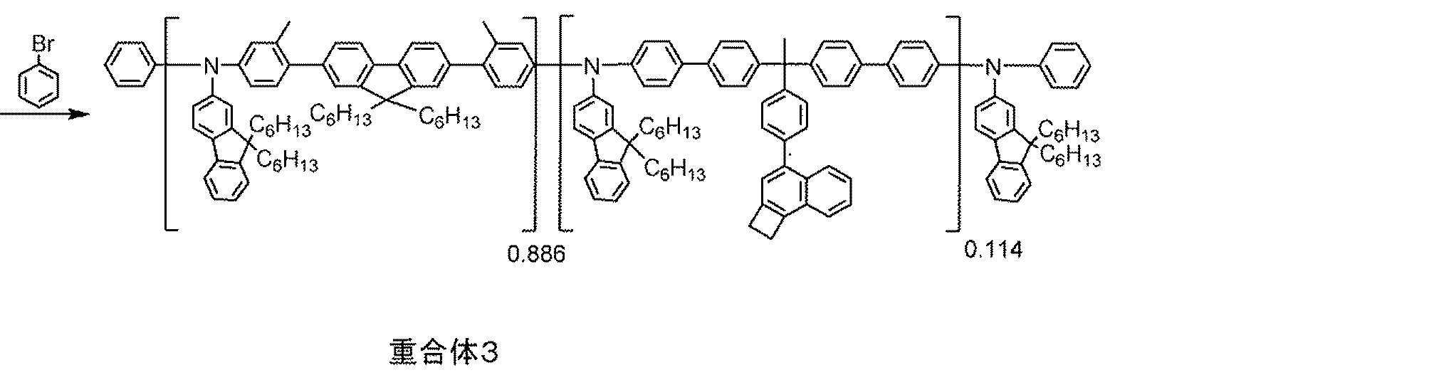
式(CzP)で表わされる部分構造を有する重合体の重量平均分子量は、通常3,000,000以下、好ましくは1,000,000以下、より好ましくは500,000以下、さらに好ましくは200,000以下、特に好ましくは100,000以下である。また、通常2,500以上、好ましくは5,000以上、より好ましくは10,000以上、さらに好ましくは20,000以上、特に好ましくは30,000以上である。
式(CzP)で表わされる部分構造を有する重合体の具体例を以下に示すが、式(CzP)で表わされる部分構造を有する重合体はこれらに限定されるものではない。なお、化学式中の数字は繰返し単位のモル比を表す。
これらの重合体は、ランダム共重合体、交互共重合体、ブロック共重合体、又はグラフト共重合体等のいずれでもよく、単量体の配列順序には限定されない。
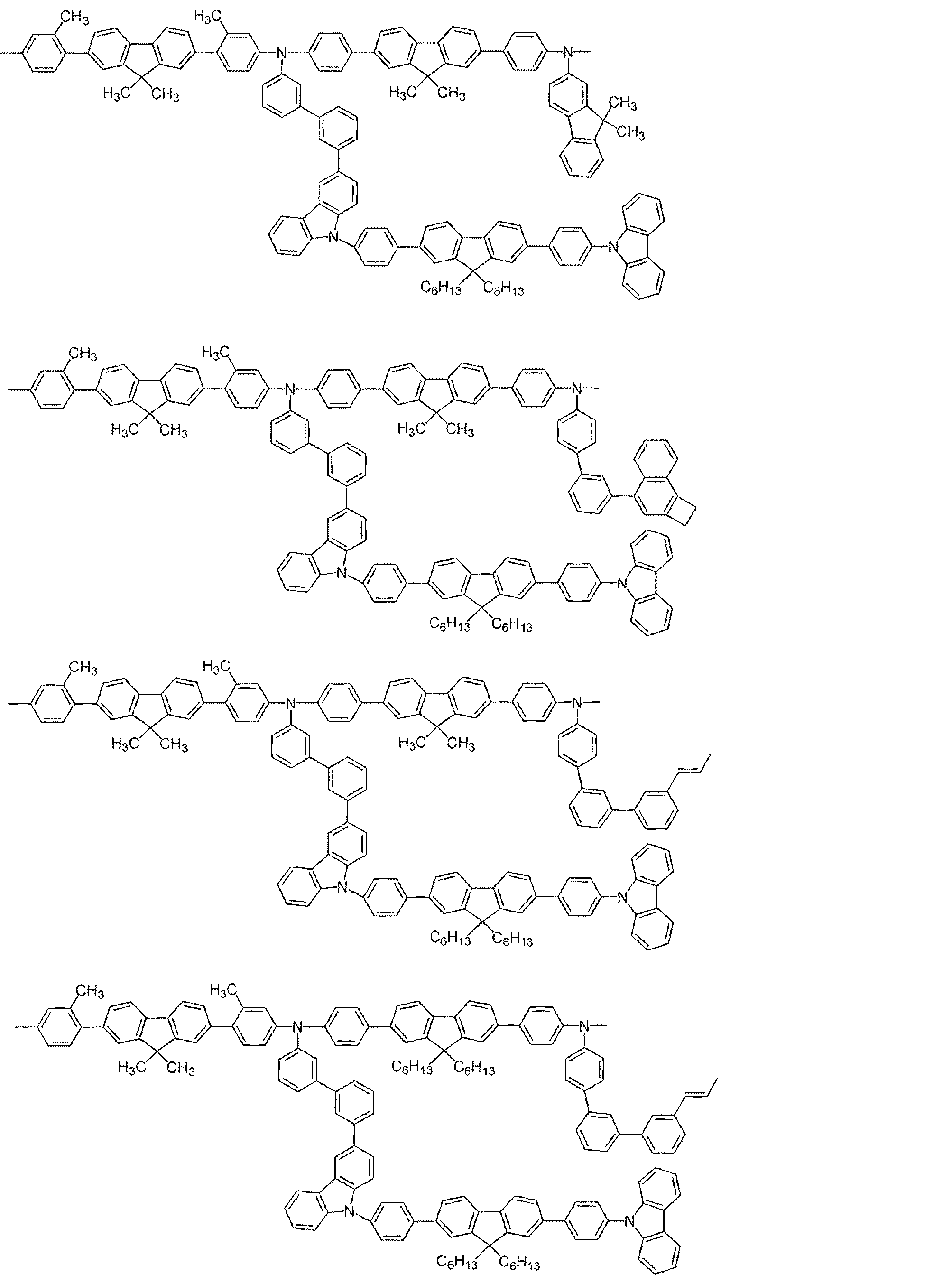

式(CzP)で表わされる部分構造を有する重合体の製造方法は特には制限されず、式(CzP)で表わされる部分構造を有する重合体が得られる限り任意である。例えば、Suzuki反応による重合方法、Grignard反応による重合方法、Yamamoto反応による重合方法、Ullmann反応による重合方法、Buchwald-Hartwig反応による重合方法等などによって製造できる。
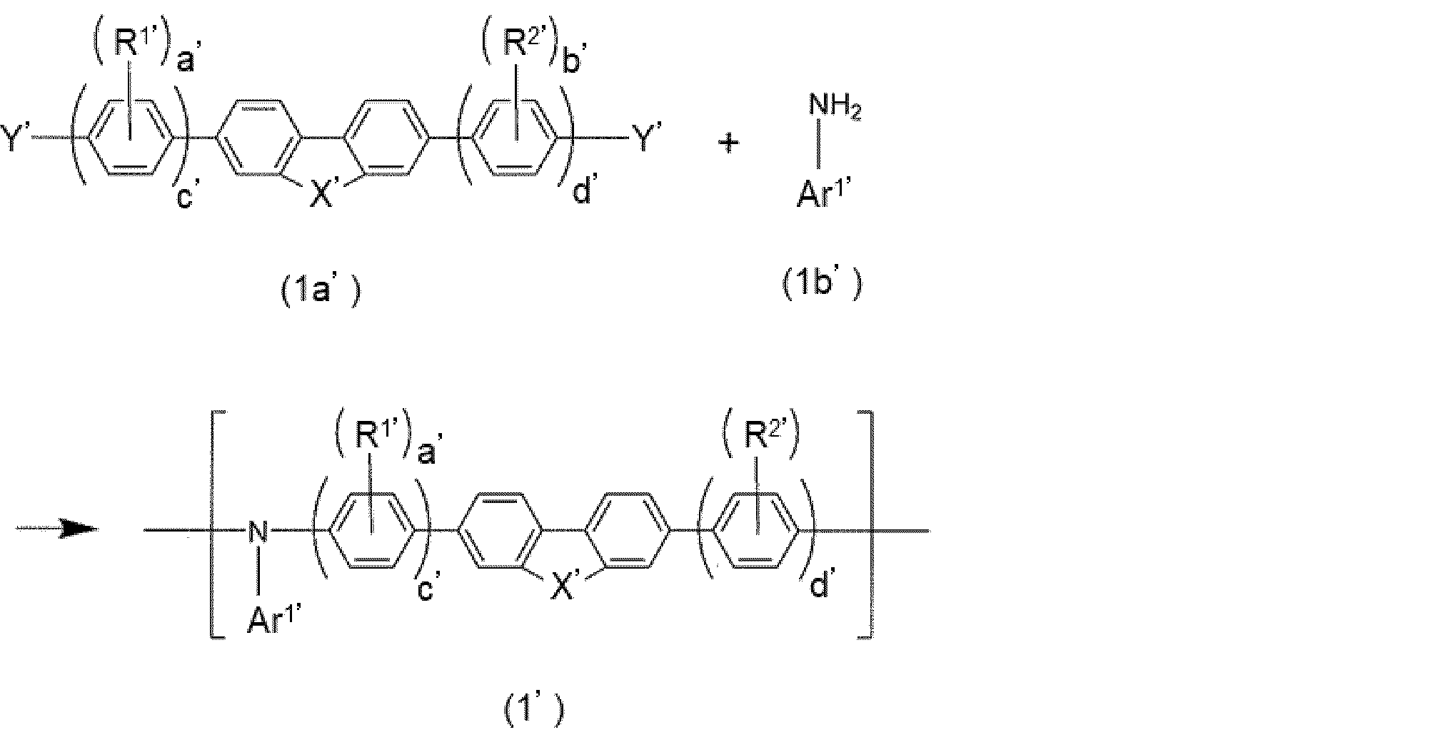
る。
なお、前記の重合方法において、通常、N-アリール結合を形成する反応は、例えば炭酸カリウム、tert-ブトキシナトリウム、トリエチルアミン等の塩基存在下で行う。また、例えば銅やパラジウム錯体等の遷移金属触媒存在下で行うこともできる。
本発明の第3の要旨における、発光層に含まれるカルバゾール環を有する特定の構造である前記式(CzP)を部分構造として含む材料が低分子材料である場合、本発明の第2の要旨における発光層に含まれる上述の低分子化合物と同様である。すなわち、前記式(CzP-2)を有するホスト材料であることが好ましく、好ましい範囲も同様である。
本発明の第2の要旨及び第3の要旨の実施形態である有機電界発光素子の正孔輸送層および正孔輸送層に隣接する発光層は、式(CzP)を部分構造として有する材料を溶媒に溶解した組成物を用いて、湿式成膜することができる。
正孔輸送層を形成するための有機電界発光素子用組成物は、上述の重合体1~重合体3のいずれかを含有することが好ましく、発光層を形成するための有機電界発光素子用組成物は、上述の低分子化合物を含有することが好ましい。
前記組成物中の式(CzP)を部分構造として有する材料の含有量は、通常0.01~70質量%、好ましくは0.1~60質量%、さらに好ましくは0.5~50質量%である。
上記範囲内であると、形成した有機層に欠陥が生じ難く、また膜厚ムラが生じ難いため好ましい。
前記組成物は、通常、溶媒を含有する。この溶媒は、式(CzP)を部分構造として有する材料を溶解するものが好ましい。具体的には、式(CzP)を部分構造として有する材料を、室温で通常0.05質量%以上、好ましくは0.5質量%以上、さらに好ましくは1質量%以上溶解する溶媒が好適である。
中でも、有機電界発光素子用組成物に含有される溶媒としては、20℃における表面張力が、通常40dyn/cm未満、好ましくは36dyn/cm以下、より好ましくは33dyn/cm以下である溶媒が好ましい。
低表面張力の溶媒の具体例としては、前述したトルエン、キシレン、メシチレン、シクロヘキシルベンゼン等の芳香族系溶媒、安息香酸エチル等のエステル系溶媒、アニソール等のエーテル系溶媒、トリフルオロメトキシアニソール、ペンタフルオロメトキシベンゼン、3-(トリフルオロメチル)アニソール、エチル(ペンタフルオロベンゾエート)等が挙げられる。
ところで、水分は有機電界発光素子の性能劣化を引き起こす可能性があり、中でも特に連続駆動時の輝度低下を促進する可能性がある。そこで、湿式成膜中に残留する水分をできる限り低減するために、前記の溶媒の中でも、25℃における水の溶解度が1質量%以下であるものが好ましく、0.1質量%以下である溶媒がより好ましい。
有機電界発光素子用組成物は、低抵抗化する点で、さらに電子受容性化合物を含有することが好ましい。特に、有機電界発光素子用組成物を正孔注入層を形成するために用いる場合には電子受容性化合物を含有することが好ましい。
電子受容性化合物としては、酸化力を有し、上述の重合体から一電子受容する能力を有する化合物が好ましい。具体的には、電子親和力が4eV以上である化合物が好ましく、5eV以上の化合物である化合物がさらに好ましい。
このような電子受容性化合物としては、例えば、トリアリールホウ素化合物、ハロゲン化金属、ルイス酸、有機酸、オニウム塩、アリールアミンとハロゲン化金属との塩、及び、アリールアミンとルイス酸との塩よりなる群から選ばれる1種又は2種以上の化合物等が挙げられる。
有機電界発光素子用組成物が電子受容性化合物を含む場合、有機電界発光素子用組成物の電子受容性化合物の含有量は、通常0.0005質量%以上、好ましくは0.001質量%以上であり、通常20質量%以下、好ましくは10質量%以下である。また、有機電界発光素子用組成物中の重合体に対する電子受容性化合物の割合は、通常0.5質量%以上、好ましくは1質量%以上、より好ましくは3質量%以上であり、通常80質量%以下、好ましくは60質量%以下、さらに好ましくは40質量%以下である。
有機電界発光素子用組成物中の電子受容性化合物の含有量が上記下限以上であると重合体から電子受容体が電子を受容し、形成した有機層が低抵抗化するため好ましく、上記上限以下であると形成した有機層に欠陥が生じ難く、また膜厚ムラが生じ難いため好ましい。
有機電界発光素子用組成物は、更にカチオンラジカル化合物を含有していてもよい。
カチオンラジカル化合物としては、正孔輸送性化合物から一電子取り除いた化学種であるカチオンラジカルと、対アニオンとからなるイオン化合物が好ましい。但し、カチオンラジカルが正孔輸送性の高分子化合物由来である場合、カチオンラジカルは高分子化合物の繰り返し単位から一電子取り除いた構造となる。
また、カチオンラジカルとしては、後述の正孔輸送性化合物から一電子取り除いた化学種であることが好ましい。正孔輸送性化合物として好ましい化合物から一電子取り除いた化学種であることが、非晶質性、可視光の透過率、耐熱性、及び溶解性等の点から好適である。
なお、有機電界発光素子用組成物には、上記の成分以外に、後述の正孔注入層形成用組成物や正孔輸送層形成用組成物に含まれる成分を、後述の含有量で含有していてもよい。
本発明における有機電界発光素子は、基板上に、陽極、陰極、及び該陽極と該陰極の間に有機層を有する有機電界発光素子である。本発明の第1の要旨の実施形態における有機電界発光素子は、有機層が、上述の重合体1又は該重合体1が架橋した重合体を含有する層を有する。本発明の第2の要旨の実施形態における有機電界発光素子は、該有機層が、正孔輸送層と、正孔輸送層に隣接する発光層とを有し、該正孔輸送層が上述の重合体1又は該重合体1が架橋した重合体を含有し、該発光層が上述の式(CzP)で表わされる部分構造を有する材料を含む。本発明の第3の要旨の実施形態における有機電界発光素子は、正孔輸送層と、正孔輸送層に隣接する発光層とを有し、該正孔輸送層と、該発光層に含まれる材料の少なくとも一つとがともにカルバゾール環を有する上述の式(CzP)で表わされる部分構造を有する材料(化合物)を含む。第3の要旨の実施形態においては、正孔輸送層に含まれる式(CzP)で表わされる部分構造を有する材料が、前記重合体2又は前記重合体2が架橋した重合体、又は、前記重合体3又は前記重合体3が架橋した重合体であることが好ましい。
上記の各実施形態に係る有機電界発光素子におけるそれぞれの条件や態様は任意に組み合わせることができる。これらの有機電界発光素子に適用し得る製造方法や特性の具体的な説明を以下に示す。
以下、有機電界発光素子の層構成及びその一般的形成方法等の実施の形態の一例を、図1を参照して説明する。
基板1は、有機電界発光素子の支持体となるものであり、通常、石英やガラスの板、金属板や金属箔、プラスチックフィルムやシート等が用いられる。これらのうち、ガラス板や、ポリエステル、ポリメタクリレート、ポリカーボネート、ポリスルホン等の透明な合成樹脂の板が好ましい。基板は、外気による有機電界発光素子の劣化が起こり難いことからガスバリア性の高い材質とするのが好ましい。このため、特に合成樹脂製の基板等のようにガスバリア性の低い材質を用いる場合は、基板の少なくとも片面に緻密なシリコン酸化膜等を設けてガスバリア性を上げるのが好ましい。
陽極2は、発光層5側の層に正孔を注入する機能を担う。
陽極2は、通常、アルミニウム、金、銀、ニッケル、パラジウム、白金等の金属;インジウム及び/又はスズの酸化物等の金属酸化物;ヨウ化銅等のハロゲン化金属;カーボンブラック及びポリ(3-メチルチオフェン)、ポリピロール、ポリアニリン等の導電性高分子等により構成される。
陽極2の厚みは、必要とされる透明性と材質等に応じて決めればよい。特に高い透明性が必要とされる場合は、可視光の透過率が60%以上となる厚みが好ましく、80%以上となる厚みが更に好ましい。陽極2の厚みは、通常5nm以上、好ましくは10nm以上であり、また、通常1000nm以下、好ましくは500nm以下とするのが好ましい。一方、透明性が不要な場合は、陽極2の厚みは必要な強度等に応じて任意に厚みとすればよく、この場合、陽極2は基板と同一の厚みでもよい。
陽極2の表面に他の層を成膜する場合は、成膜前に、紫外線/オゾン、酸素プラズマ、アルゴンプラズマ等の処理を施すことにより、陽極2上の不純物を除去すると共に、そのイオン化ポテンシャルを調整して正孔注入性を向上させておくことが好ましい。
陽極2側から発光層5側に正孔を輸送する機能を担う層は、通常、正孔注入輸送層又は正孔輸送層と呼ばれる。そして、陽極2側から発光層5側に正孔を輸送する機能を担う層が2層以上ある場合に、より陽極側に近い方の層を正孔注入層3と呼ぶことがある。正孔注入層3は、陽極2から発光層5側に正孔を輸送する機能を強化する点で、形成することが好ましい。正孔注入層3を形成する場合、通常、正孔注入層3は、陽極2上に形成される。
正孔注入層の形成方法は、真空蒸着法でも、湿式成膜法でもよい。成膜性が優れる点では、湿式成膜法により形成することが好ましい。
正孔注入層3は、正孔輸送性化合物を含むことが好ましく、正孔輸送性化合物と電子受容性化合物とを含むことがより好ましい。更には、正孔注入層中にカチオンラジカル化合物を含むことが好ましく、カチオンラジカル化合物と正孔輸送性化合物とを含むことが特に好ましい。
以下に、一般的な正孔注入層の形成方法について説明するが、有機電界発光素子において、正孔注入層は、有機電界発光素子用組成物を用いて湿式成膜法により形成されることが好ましい。
正孔注入層形成用組成物は、通常、正孔注入層3となる正孔輸送性化合物を含有する。また、湿式成膜法の場合は、通常、更に溶媒も含有する。正孔注入層形成用組成物は、正孔輸送性が高く、注入された正孔を効率よく輸送できるのが好ましい。このため、正孔移動度が大きく、トラップとなる不純物が製造時や使用時等に発生し難いことが好ましい。また、安定性に優れ、イオン化ポテンシャルが小さく、可視光に対する透明性が高いことが好ましい。特に、正孔注入層が発光層と接する場合は、発光層からの発光を消光しないものや発光層とエキサイプレックスを形成して、発光効率を低下させないものが好ましい。
芳香族三級アミン化合物の種類は、特に制限されないが、表面平滑化効果により均一な発光を得やすい点から、重量平均分子量が1000以上、1000000以下の高分子化合物(繰り返し単位が連なる重合型化合物)を用いることが好ましい。
PEDOT/PSS(Adv.Mater.,2000年,12巻,481頁)やエメラルジン塩酸塩(J.Phys.Chem.,1990年,94巻,7716頁)等の高分子化合物由来のカチオンラジカル化合物は、酸化重合(脱水素重合)することによっても生成する。
湿式成膜法により正孔注入層3を形成する場合、通常、正孔注入層となる材料を可溶な溶媒(正孔注入層用溶媒)と混合して成膜用の組成物(正孔注入層形成用組成物)を調製し、この正孔注入層形成用組成物を正孔注入層の下層に該当する層(通常は、陽極)上に塗布して成膜し、乾燥させることにより形成する。
エーテル系溶媒としては、例えば、エチレングリコールジメチルエーテル、エチレングリコールジエチルエーテル、プロピレングリコール-1-モノメチルエーテルアセタート(PGMEA)等の脂肪族エーテル及び1,2-ジメトキシベンゼン、1,3-ジメトキシベンゼン、アニソール、フェネトール、2-メトキシトルエン、3-メトキシトルエン、4-メトキシトルエン、2,3-ジメチルアニソール、2,4-ジメチルアニソール等の芳香族エーテル等が挙げられる。
芳香族炭化水素系溶媒としては、例えば、トルエン、キシレン、シクロヘキシルベンゼン、3-イソプロピルビフェニル、1,2,3,4-テトラメチルベンゼン、1,4-ジイソプロピルベンゼン、シクロヘキシルベンゼン、メチルナフタレン等が挙げられる。
これらの他、ジメチルスルホキシド等も用いることができる。
正孔注入層3の湿式成膜法による形成は、通常、正孔注入層形成用組成物を調製後に、これを、正孔注入層3の下層に該当する層(通常は、陽極2)上に塗布成膜し、乾燥することにより行われる。
正孔注入層3は、通常、成膜後に、加熱や減圧乾燥等により塗布膜を乾燥させる。
真空蒸着法により正孔注入層3を形成する場合には、通常、正孔注入層3の構成材料(前述の正孔輸送性化合物、電子受容性化合物等)の1種類又は2種類以上を真空容器内に設置された坩堝に入れ(2種類以上の材料を用いる場合は、通常各々を別々の坩堝に入れ)、真空容器内を真空ポンプで10-4Pa程度まで排気した後、坩堝を加熱して(2種類以上の材料を用いる場合は、通常各々の坩堝を加熱して)、坩堝内の材料の蒸発量を制御しながら蒸発させ(2種類以上の材料を用いる場合は、通常各々独立に蒸発量を制御しながら蒸発させ)、坩堝に向き合って置かれた基板上の陽極上に正孔注入層を形成する。なお、2種類以上の材料を用いる場合は、それらの混合物を坩堝に入れ、加熱、蒸発させて正孔注入層を形成することもできる。
なお、正孔注入層3は、後述の正孔輸送層4と同様に架橋されていてもよい。
正孔輸送層4は、陽極2側から発光層5側に正孔を輸送する機能を担う層である。本実施形態においては正孔輸送層4と発光層5は接しており、正孔輸送層4が式(CzP)で表わされる部分構造を有する材料を含む層である。正孔輸送層4を形成する場合、通常、正孔輸送層4は、陽極2と発光層5の間に形成される。また、上述の正孔注入層3がある場合は、正孔注入層3と発光層5の間に形成される。
正孔輸送層4の形成方法は、真空蒸着法でも、湿式成膜法でもよい。成膜性が優れる点では、湿式成膜法により形成することが好ましい。
以下に一般的な正孔輸送層の形成方法について説明するが、有機電界発光素子において、正孔輸送層は、有機電界発光素子用組成物を用いて湿式成膜法により形成されることが好ましい。
正孔輸送層4は、通常、正孔輸送性化合物を含有する。正孔輸送層4に含まれる正孔輸送性化合物としては、上述の重合体、または上述の重合体が架橋性基を有する場合は重合体が架橋した重合体が好ましい。さらに、重合体の他に、前記正孔輸送性化合物、4,4’-ビス[N-(1-ナフチル)-N-フェニルアミノ]ビフェニルで代表される、2個以上の3級アミンを含み2個以上の縮合芳香族環が窒素原子に置換した芳香族ジアミン(特開平5-234681号公報)、4,4’,4’’-トリス(1-ナフチルフェニルアミノ)トリフェニルアミン等のスターバースト構造を有する芳香族アミン化合物(J.Lumin.,72-74巻、985頁、1997年)、トリフェニルアミンの四量体から成る芳香族アミン化合物(Chem.Commun.,2175頁、1996年)、2,2’,7,7’-テトラキス-(ジフェニルアミノ)-9,9’-スピロビフルオレン等のスピロ化合物(Synth.Metals,91巻、209頁、1997年)、4,4’-N,N’-ジカルバゾールビフェニル等のカルバゾール誘導体等が好ましいものとして挙げられる。また、例えばポリビニルカルバゾール、ポリビニルトリフェニルアミン(特開平7-53953号公報)、テトラフェニルベンジジンを含有するポリアリーレンエーテルサルホン(Polym.Adv.Tech.,7巻、33頁、1996年)等を含んでもよい。
湿式成膜法で正孔輸送層を形成する場合は、通常、上述の正孔注入層を湿式成膜法で形成する場合と同様にして、正孔注入層形成用組成物の代わりに正孔輸送層形成用組成物を用いて形成させる。
湿式成膜法で正孔輸送層を形成する場合は、通常、正孔輸送層形成用組成物は、更に溶媒を含有する。正孔輸送層形成用組成物に用いる溶媒は、上述の正孔注入層形成用組成物で用いる溶媒と同様の溶媒を使用することができる。
正孔輸送層形成用組成物中における正孔輸送性化合物の濃度は、正孔注入層形成用組成物中における正孔輸送性化合物の濃度と同様の範囲とすることができる。
正孔輸送層の湿式成膜法による形成は、前述の正孔注入層成膜法と同様に行うことができる。
真空蒸着法で正孔輸送層を形成する場合についても、通常、上述の正孔注入層を真空蒸着法で形成する場合と同様にして、正孔注入層形成用組成物の代わりに正孔輸送層形成用組成物を用いて形成させることができる。蒸着時の真空度、蒸着速度及び温度等の成膜条件などは、前記正孔注入層の真空蒸着時と同様の条件で成膜することができる。
発光層5は、一対の電極間に電界が与えられた時に、陽極2から注入される正孔と陰極9から注入される電子が再結合することにより励起され、発光する機能を担う層である。発光層5は、陽極2と陰極9の間に形成される層であり、発光層は、陽極の上に正孔注入層がある場合は、正孔注入層と陰極の間に形成され、陽極の上に正孔輸送層がある場合は、正孔輸送層と陰極の間に形成される。
発光材料は燐光発光材料または蛍光発光材料を用いることができる。
本発明の第2の要旨及び第3の要旨にかかる実施形態における有機電界発光素子においては、発光層は式(CzP)で表わされる部分構造を有する材料を含む。発光層は、式(CzP)で表わされる部分構造を有する材料以外の材料を含んでもよい。
発光層が燐光発光層である場合、燐光発光材料としては以下の材料が好ましい。
燐光発光材料とは、励起三重項状態から発光を示す材料をいう。例えば、Ir、Pt、Euなどを有する金属錯体化合物がその代表例であり、材料の構造として、金属錯体を含むものが好ましい。
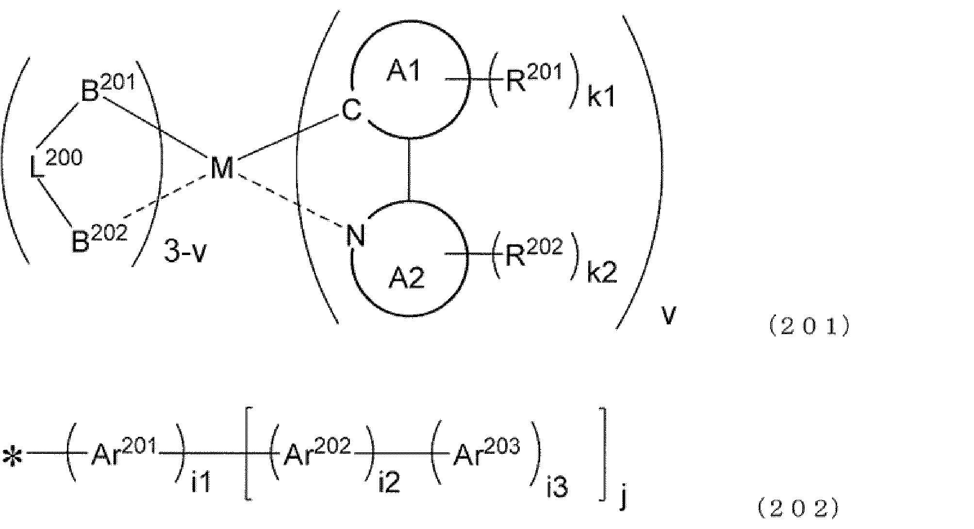
環A2は置換基を有していてもよい芳香族複素環構造を表す。
R201、R202は各々独立に式(202)で表わされる構造であり、式(202)における“*”は環A1または環A2との結合を表す。R201、R202は同じであっても異なっていてもよく、R201、R202がそれぞれ複数存在する場合、それらは同じであっても異なっていてもよい。
Ar202は、置換基を有していてもよい芳香族炭化水素環構造、置換基を有していてもよい芳香族複素環構造、または置換基を有していてもよい脂肪族炭化水素構造を表す。
環A201に結合する置換基どうし、環A2に結合する置換基どうし、または環A1に結合する置換基と環A2に結合する置換基どうしは、互いに結合して環を形成してもよい。
i3は、Ar202に置換可能な数を上限とする0以上の整数である。
jは、Ar201に置換可能な数を上限とする0以上の整数である。
k1、k2はそれぞれ独立に、環A1、環A2に置換可能な数を上限とする0以上の整数である。
vは1~3の整数である。
式(201)及び(202)における各基について、特に指定が無い場合、有していてもよい置換基としては、次の置換基群Z2から選ばれる基が好ましい。
・アルキル基、好ましくは炭素数1~20のアルキル基、より好ましくは炭素数1~12のアルキル基、さらに好ましくは炭素数1~8のアルキル基、特に好ましくは炭素数1~6のアルキル基。
・アルコキシ基、好ましくは炭素数1~20のアルコキシ基、より好ましくは炭素数1~12のアルコキシ基、さらに好ましくは炭素数1~6のアルコキシ基。
・アリールオキシ基、好ましくは炭素数6~20のアリールオキシ基、より好ましくは炭素数6~14のアリールオキシ基、さらに好ましくは炭素数6~12のアリールオキシ基、特に好ましくは炭素数6のアリールオキシ基。
・ヘテロアリールオキシ基、好ましくは炭素数3~20のヘテロアリールオキシ基、より好ましくは炭素数3~12のヘテロアリールオキシ基。
・アルキルアミノ基、好ましくは炭素数1~20のアルキルアミノ基、より好ましくは炭素数1~12のアルキルアミノ基。
・アリールアミノ基、好ましくは炭素数6~36のアリールアミノ基、より好ましくは炭素数6~24のアリールアミノ基。
・アラルキル基、好ましくは炭素数7~40のアラルキル基、より好ましくは炭素数7~18のアラルキル基、さらに好ましくは炭素数7~12のアラルキル基。
・ヘテロアラルキル基、好ましくは炭素数7~40のヘテロアラルキル基、より好ましくは炭素数7~18のヘテロアラルキル基、
・アルケニル基、好ましくは炭素数2~20のアルケニル基、より好ましくは炭素数2~12のアルケニル基、さらに好ましくは炭素数2~8のアルケニル基、特に好ましくは炭素数2~6のアルケニル基。
・アルキニル基、好ましくは炭素数2~20のアルキニル基、より好ましくは炭素数2~12のアルキニル基。
・アリール基、好ましくは炭素数6~30のアリール基、より好ましくは炭素数6~24のアリール基、さらに好ましくは炭素数6~18のアリール基、特に好ましくは炭素数6~14のアリール基。
・ヘテロアリール基、好ましくは炭素数3~30のヘテロアリール基、より好ましくは炭素数3~24のヘテロアリール基、さらに好ましくは炭素数3~18のヘテロアリール基、特に好ましくは炭素数3~14のヘテロアリール基。
・アルキルシリル基、好ましくはアルキル基の炭素数が1~20であるアルキルシリル基、より好ましくはアルキル基の炭素数が1~12であるアルキルシリル基。
・アリールシリル基、好ましくはアリール基の炭素数が6~20であるアリールシリル基、より好ましくはアリール基の炭素数が6~14であるアリールシリル基。
・アルキルカルボニル基、好ましくは炭素数2~20のアルキルカルボニル基。
・アリールカルボニル基、好ましくは炭素数7~20のアリールカルボニル基。
特に断りのない限り、アリールは芳香族炭化水素であり、ヘテロアリールは芳香族複素環である。
・水素原子、重水素原子、フッ素原子、シアノ基、または、-SF5。
これら置換基群Z2のうち、好ましくは、アルキル基、アルコキシ基、アリールオキシ基、アリールアミノ基、アラルキル基、アルケニル基、アリール基、ヘテロアリール基、アルキルシリル基、アリールシリル基、およびこれらの基の一つ以上の水素原子がフッ素原子で置き換えられている基、フッ素原子、シアノ基、または、-SF5であり、より好ましくはアルキル基、アリールアミノ基、アラルキル基、アルケニル基、アリール基、ヘテロアリール基であり、およびこれらの基の一つ以上の水素原子がフッ素原子で置き換えられている基、フッ素原子、シアノ基、または、-SF5であり、さらに好ましくは、アルキル基、アルコキシ基、アリールオキシ基、アリールアミノ基、アラルキル基、アルケニル基、アリール基、ヘテロアリール基、アルキルシリル基、アリールシリル基であり、特に好ましくはアルキル基、アリールアミノ基、アラルキル基、アルケニル基、アリール基、ヘテロアリール基であり、最も好ましくはアルキル基、アリールアミノ基、アラルキル基、アリール基、ヘテロアリール基である。
環A1は置換基を有していてもよい芳香族炭化水素環構造または置換基を有していてもよい芳香族複素環構造を表す。
芳香族複素環としては、ヘテロ原子として窒素原子、酸素原子、または硫黄原子のいずれかを含む、炭素数3~30の芳香族複素環が好ましく、さらに好ましくは、フラン環、ベンゾフラン環、チオフェン環、ベンゾチオフェン環である。
環A2は置換基を有していてもよい芳香族複素環構造を表す。
芳香族複素環としては、好ましくはヘテロ原子として窒素原子、酸素原子、または硫黄原子のいずれかを含む、炭素数3~30の芳香族複素環であり、具体的には、ピリジン環、ピリミジン環、ピラジン環、トリアジン環、イミダゾール環、オキサゾール環、チアゾール環、ベンゾチアゾール環、ベンゾオキサゾール環、ベンゾイミダゾール環、キノリン環、イソキノリン環、キノキサリン環、キナゾリン環、ナフチリジン環、フェナントリジン環が挙げられ、さらに好ましくは、ピリジン環、ピラジン環、ピリミジン環、イミダゾール環、ベンゾチアゾール環、ベンゾオキサゾール環、キノリン環、イソキノリン環、キノキサリン環、キナゾリン環であり、より好ましくは、ピリジン環、イミダゾール環、ベンゾチアゾール環、キノリン環、イソキノリン環、キノキサリン環、キナゾリン環であり、最も好ましくは、ピリジン環、イミダゾール環、ベンゾチアゾール環、キノリン環、キノキサリン環、キナゾリン環である。
環A1、環A2が有していてもよい置換基は任意に選択できるが、好ましくは前記置換基群Z2から選ばれる1種または複数種の置換基である。
Ar202は、置換基を有していてもよい芳香族炭化水素環構造、置換基を有していてもよい芳香族複素環構造、または置換基を有していてもよい脂肪族炭化水素構造を表す。
Ar201、Ar202、Ar203のいずれかが置換基を有していてもよい芳香族炭化水素環構造である場合、芳香族炭化水素環構造としては、好ましくは炭素数6~30の芳香族炭化水素環であり、具体的には、ベンゼン環、ナフタレン環、アントラセン環、トリフェニリル環、アセナフテン環、フルオランテン環、フルオレン環が好ましく、より好ましくは、ベンゼン環、ナフタレン環、フルオレン環が好ましく、最も好ましくはベンゼン環である。
Ar201、Ar202、Ar203のいずれかが置換基を有していてもよいベンゼン環である場合、少なくとも一つのベンゼン環がオルト位またはメタ位で隣接する構造と結合していることが好ましく、少なくとも一つのベンゼン環がメタ位で隣接する構造と結合していることがより好ましい。
Ar2が置換基を有していてもよい脂肪族炭化水素構造である場合、直鎖、分岐鎖、または環状構造を有する脂肪族炭化水素構造であり、好ましくは炭素数が1以上24以下であり、さらに好ましくは炭素数が1以上12以下であり、より好ましくは炭素数が1以上8以下である。
i3は好ましくは0~5の整数を表し、さらに好ましくは0~2、より好ましくは0または1である。
k1、k2は好ましくは0~3の整数を表し、さらに好ましくは1~3であり、より好ましくは1または2であり、特に好ましくは1である。
Ar201、Ar202、Ar203が有していてもよい置換基は任意に選択できるが、好ましくは前記置換基群Z2から選ばれる1種または複数種の置換基であり、好ましい基も前記置換基群Z2の通りであるが、より好ましくは水素原子、アルキル基、アリール基であり、特に好ましくは水素原子、アルキル基、であり、最も好ましくは無置換(水素原子)である。
B201-L200-B202は、アニオン性の2座配位子を表す。B201およびB202は、それぞれ独立に、炭素原子、酸素原子または窒素原子を表し、これらの原子は環を構成する原子であってもよい。L200は、単結合、または、B201およびB202とともに2座配位子を構成する原子団を表す。B201-L200-B202が複数存在する場合、それらは同一でも異なっていてもよい。
B201-L200-B202であらわされる構造のうち、好ましくは下記式(203)または(204)であらわされる構造である。
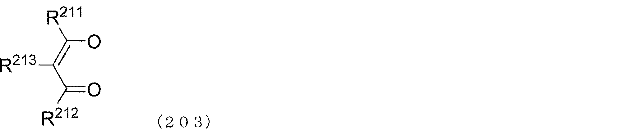
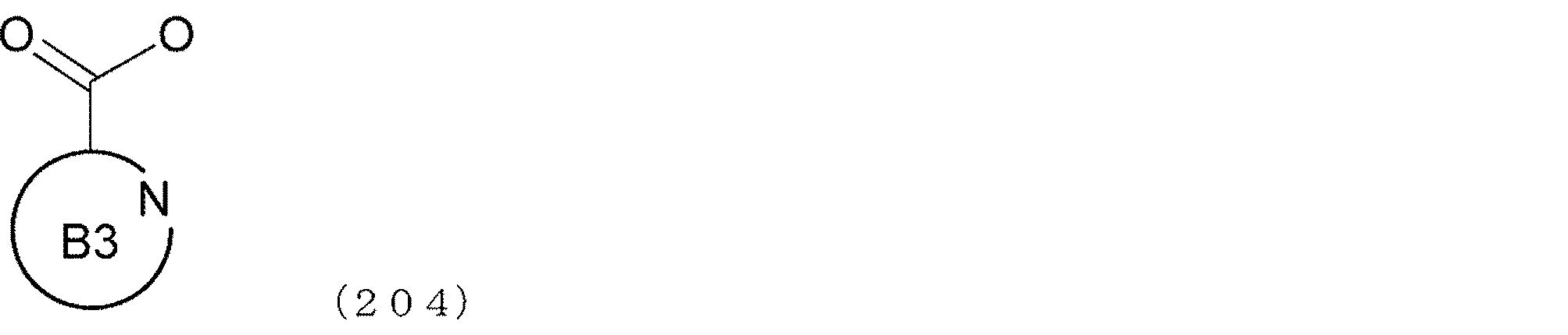
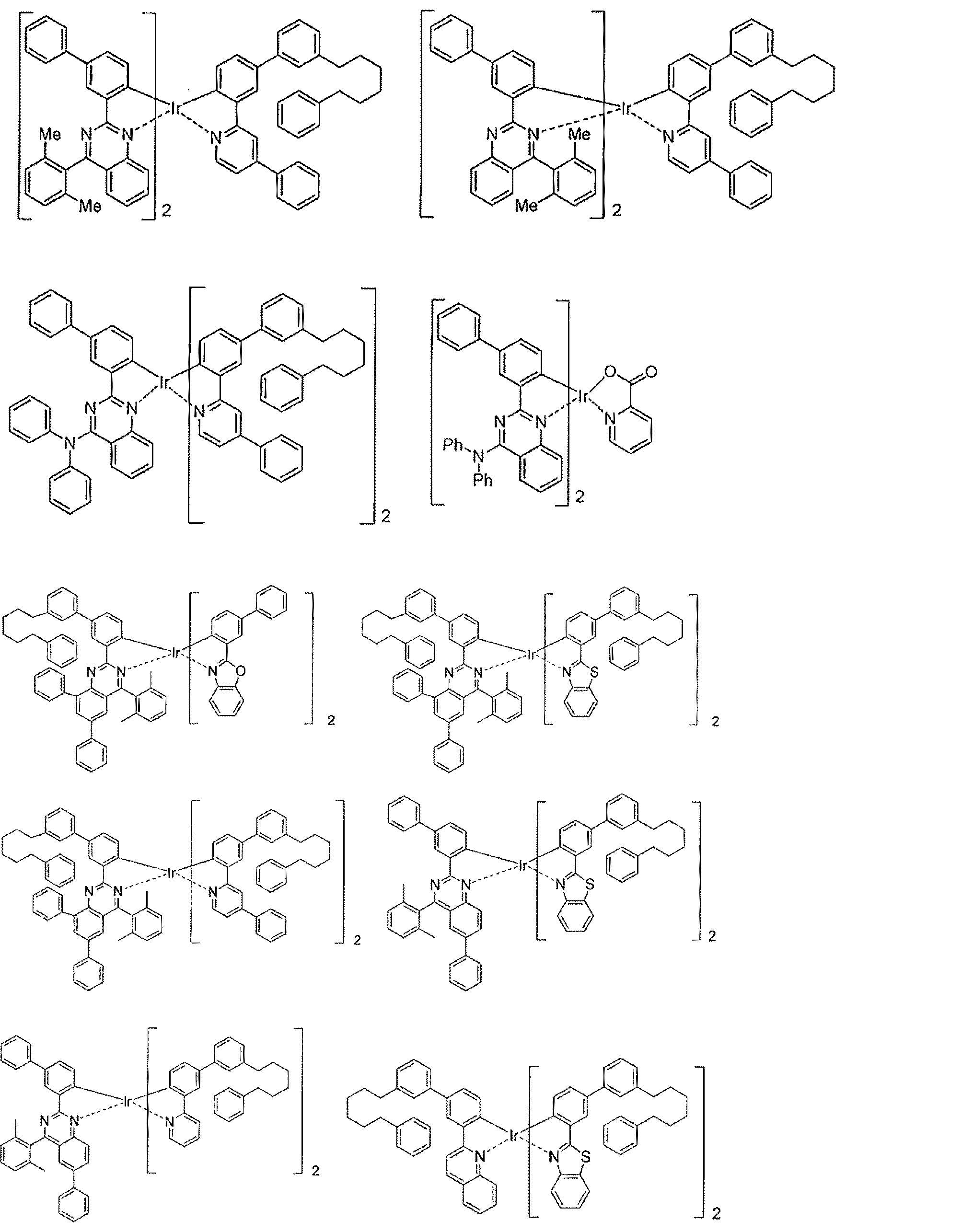
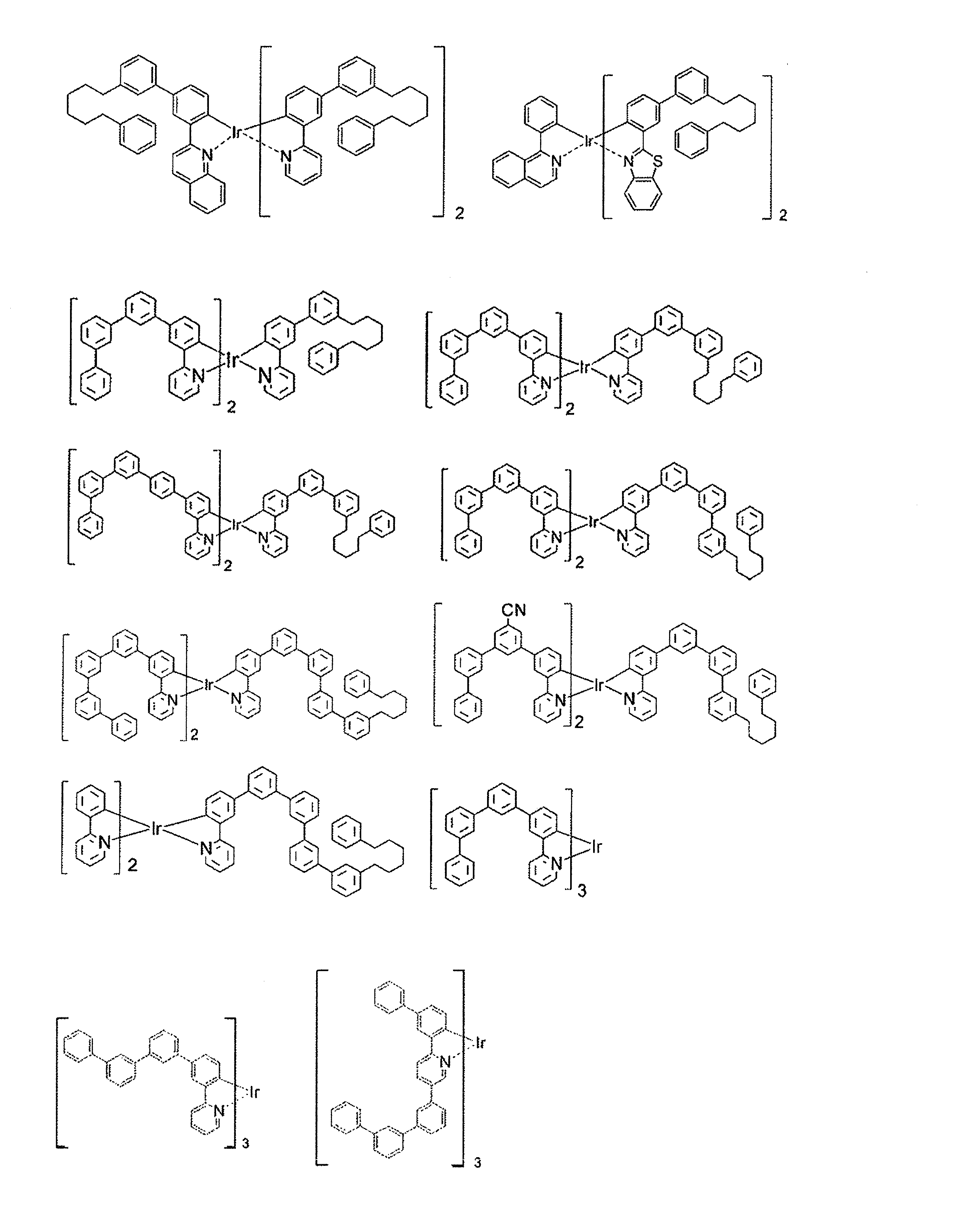
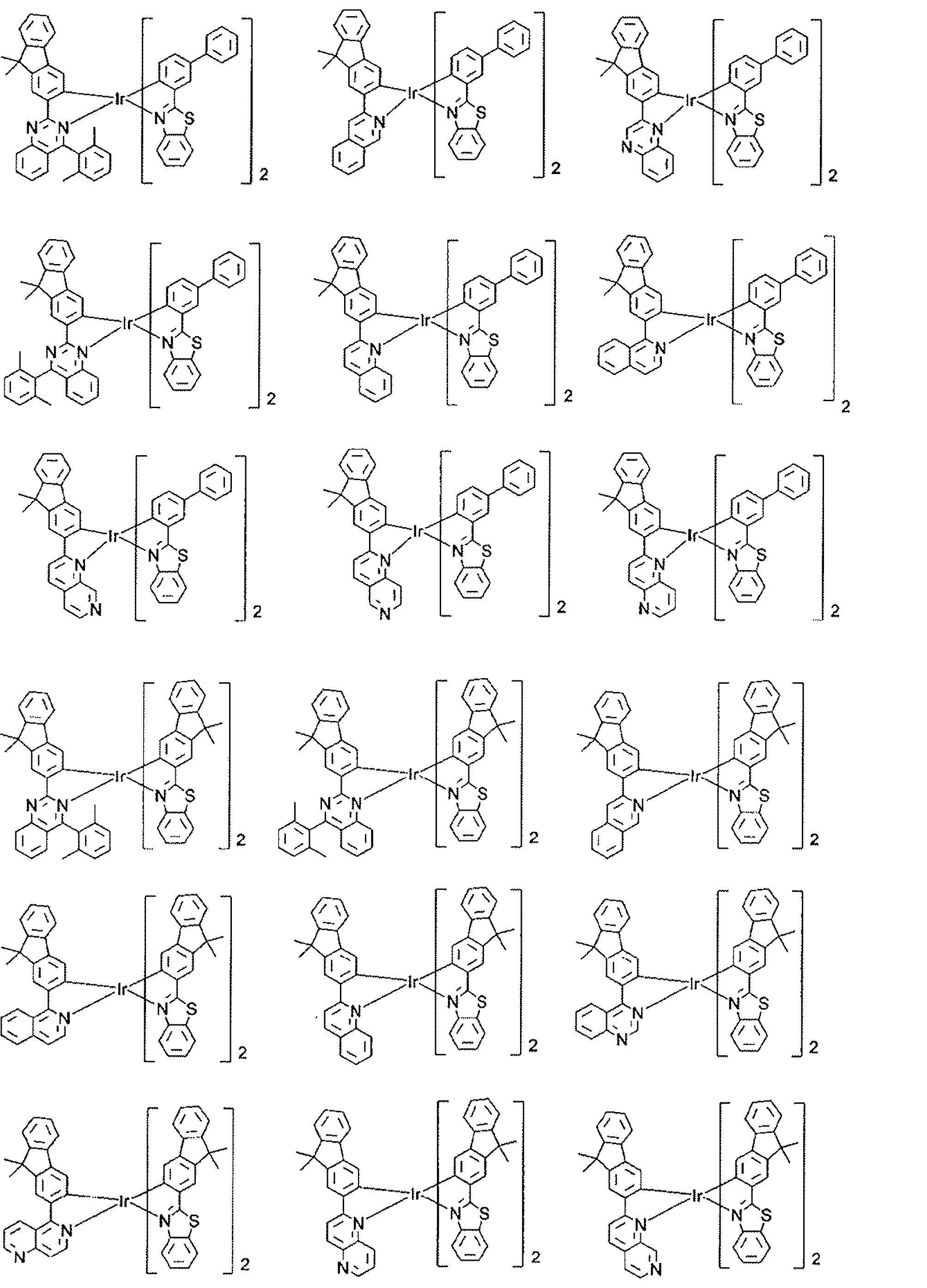
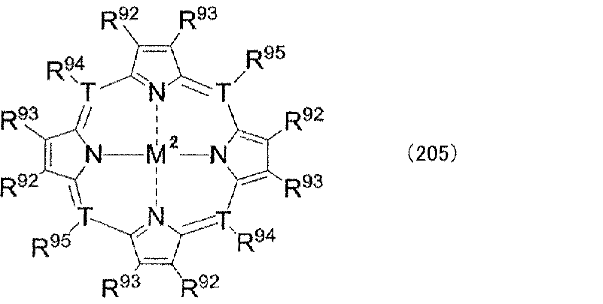
式(205)中、M2は金属を表す。具体例としては、周期表第7~11族から選ばれる金属として前述した金属が挙げられる。中でも好ましくは、ルテニウム、ロジウム、パラジウム、銀、レニウム、オスミウム、イリジウム、白金または金が挙げられ、特に好ましくは、白金、パラジウム等の二価の金属が挙げられる。
重合体を、正孔注入層及び正孔輸送層の少なくとも一方を形成する電荷輸送性材料として用いた有機電界発光素子において、発光層が燐光発光材料である場合、ホスト材料としては以下の材料が好ましい。
発光層のホスト材料(化合物)としては、前述した、式(CzP)、式(CzP-2)を有するものを用いることができる。また、発光材や、他のホスト材料が式(CzP)を有している場合は、適宜、式(CzP)、式(CzP-2)を有さないホスト材料を用いることもできる。この場合、骨格、分子量、置換基等は前述と同様である。
青蛍光発光層用発光材料としては特に限定されないが、下記式(211)で表される化合物が好ましい。

Ar241は置換基を有していてもよい芳香族炭化水素縮合環構造を表し、
Ar242、Ar243は、各々独立に、置換基を有していてもよいアルキル基、芳香族炭化水素基またはこれらが結合した基を表す。
n41は1~4である。
さらに好ましくは炭素数12~20の芳香族炭化水素縮合環構造であり、具体的な構造としては、アセナフテン、フルオレン、アントラセン、フェナトレン、フルオランテン、ピレン、テトラセン、クリセン、ペリレンがあげられる。より好ましくは炭素数16~18の芳香族炭化水素縮合環構造であり、具体的な構造としては、フルオランテン、ピレン、クリセンがあげられる。
Ar241、Ar242、Ar243が有していてもよい置換基は、前記置換基群Z2から選ばれる基が好ましく、より好ましくは置換基群Z2に含まれる、炭化水素基であり、さらに好ましくは置換基群Z2として好ましい基の中の炭化水素基である。
青蛍光発光層用ホスト材料としては特に限定されないが、下記式(212)で表される化合物が好ましい。
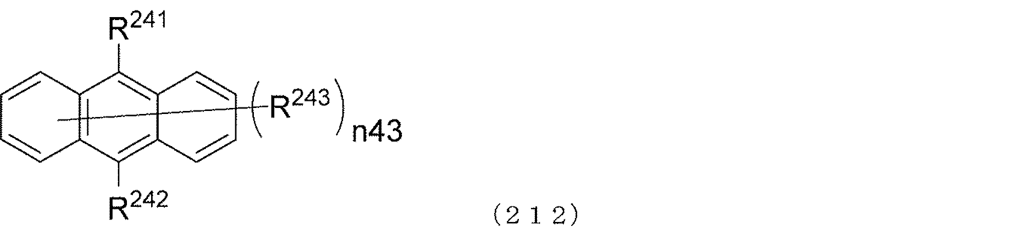
R241、R242はそれぞれ独立に式(213)で表わされる構造であり、
R243は置換基を表し、R243は複数ある場合同一であっても異なっていてもよく、
n43は0~8である。]

Ar244、Ar245はそれぞれ、複数存在する場合、同一であっても異なっていてもよく、
n44は1~5、n45は0~5である。
Ar245は好ましくは、置換基を有していてもよい、炭素数6~30の単環または縮合環である芳香族炭化水素構造、または、置換基を有していてもよい、炭素数6~30の縮合環である芳香族複素環構造であり、より好ましくは、置換基を有していてもよい、炭素数6~12の単環または縮合環である芳香族炭化水素構造、または、置換基を有していてもよい、炭素数12の縮合環である芳香族複素環構造である。
n45は好ましくは0~3であり、より好ましくは0~2である。
置換基であるR243および、Ar244およびAr245が有していてもよい置換基は、前記置換基群Zから選ばれる基が好ましく、より好ましくは置換基群Zに含まれる、炭化水素基であり、さらに好ましくは置換基群Zとして好ましい基の中の炭化水素基である。
発光層の形成方法は、真空蒸着法でも、湿式成膜法でもよいが、成膜性に優れることから、湿式成膜法が好ましく、スピンコート法及びインクジェット法が更に好ましい。特に、有機電界発光素子用組成物を用いて、発光層の下層となる正孔注入層又は正孔輸送層を形成すると、湿式成膜法による積層化が容易であるため、湿式成膜法を採用することが好ましい。湿式成膜法により発光層を形成する場合は、通常、上述の正孔注入層を湿式成膜法で形成する場合と同様にして、正孔注入層形成用組成物の代わりに、発光層となる材料を可溶な溶媒(発光層用溶媒)と混合して調製した発光層形成用組成物を用いて形成する。
発光層5と後述の電子注入層8との間に、正孔阻止層6を設けてもよい。正孔阻止層6は、発光層5の上に、発光層5の陰極9側の界面に接するように積層される層である。
この正孔阻止層6は、陽極2から移動してくる正孔を陰極9に到達するのを阻止する役割と、陰極9から注入された電子を効率よく発光層5の方向に輸送する役割とを有する。正孔阻止層6を構成する材料に求められる物性としては、電子移動度が高く正孔移動度が低いこと、エネルギーギャップ(HOMO、LUMOの差)が大きいこと、励起三重項準位(T1)が高いことが挙げられる。
正孔阻止層6の膜厚は、本発明の効果を著しく損なわない限り任意であるが、通常0.3nm以上、好ましくは0.5nm以上であり、また、通常100nm以下、好ましくは50nm以下である。
電子輸送層7は素子の電流効率をさらに向上させることを目的として、発光層5と電子注入層8との間に設けられる。
電子輸送層7は、電界を与えられた電極間において陰極9から注入された電子を効率よく発光層5の方向に輸送することができる化合物より形成される。電子輸送層7に用いられる電子輸送性化合物としては、陰極9又は電子注入層8からの電子注入効率が高く、かつ、高い電子移動度を有し、注入された電子を効率よく輸送することができる化合物であることが必要である。
電子輸送層7の膜厚は、通常1nm以上、好ましくは5nm以上であり、また、通常300nm以下、好ましくは100nm以下である。
電子輸送層7は、前記と同様にして湿式成膜法、或いは真空蒸着法により正孔阻止層6上に積層することにより形成される。通常は、真空蒸着法が用いられる。
電子注入層8は、陰極9から注入された電子を効率よく、電子輸送層7又は発光層5へ注入する役割を果たす。
電子注入を効率よく行うには、電子注入層8を形成する材料は、仕事関数の低い金属が好ましい。例としては、ナトリウムやセシウム等のアルカリ金属、バリウムやカルシウム等のアルカリ土類金属等が用いられる。その膜厚は通常0.1nm以上、5nm以下が好ましい。
更に、バソフェナントロリン等の含窒素複素環化合物や8-ヒドロキシキノリンのアルミニウム錯体等の金属錯体に代表される有機電子輸送材料に、ナトリウム、カリウム、セシウム、リチウム、ルビジウム等のアルカリ金属をドープする(特開平10-270171号公報、特開2002-100478号公報、特開2002-100482号公報等に記載)ことも、電子注入・輸送性が向上し優れた膜質を両立させることが可能となるため好ましい。
電子注入層8は、湿式成膜法或いは真空蒸着法により、発光層5又はその上の正孔阻止層6や電子輸送層7上に積層することにより形成される。
湿式成膜法の場合の詳細は、前述の発光層の場合と同様である。
陰極9は、発光層5側の層(電子注入層又は発光層など)に電子を注入する役割を果たす。
陰極9の材料としては、前記の陽極2に使用される材料を用いることが可能であるが、効率よく電子注入を行なう上では、仕事関数の低い金属を用いることが好ましく、例えば、スズ、マグネシウム、インジウム、カルシウム、アルミニウム、銀等の金属又はそれらの合金等が用いられる。具体例としては、例えば、マグネシウム-銀合金、マグネシウム-インジウム合金、アルミニウム-リチウム合金等の低仕事関数の合金電極等が挙げられる。
陰極の膜厚は通常、陽極と同様である。
有機電界発光素子は、本発明の効果を著しく損なわなければ、更に他の層を有していてもよい。すなわち、陽極と陰極との間に、上述の他の任意の層を有していてもよい。
有機電界発光素子は、上述の説明とは逆の構造、即ち、基板上に陰極、電子注入層、電子輸送層、正孔阻止層、発光層、正孔輸送層、正孔注入層、陽極の順に積層することも可能である。
有機電界発光素子を有機電界発光装置に適用する場合は、単一の有機電界発光素子として用いても、複数の有機電界発光素子がアレイ状に配置された構成にして用いても、陽極と陰極がX-Yマトリックス状に配置された構成にして用いてもよい。
本発明のさらに別の実施形態である有機EL表示装置(有機電界発光素子表示装置)は、上述の有機電界発光素子を備えたものである。有機EL表示装置の型式や構造については特に制限はなく、有機電界発光素子を用いて常法に従って組み立てることができる。
例えば、「有機ELディスプレイ」(オーム社、平成16年8月20日発行、時任静士、安達千波矢、村田英幸著)に記載されているような方法で、有機EL表示装置を形成することができる。
本発明のさらに別の実施形態である有機EL照明(有機電界発光素子照明)は、上述の有機電界発光素子を備えたものである。有機EL照明の型式や構造については特に制限はなく、有機電界発光素子を用いて常法に従って組み立てることができる。
<中間体の合成>
[化合物3の合成]

ビス(トリフェニルホスフィン)パラジウム(II)ジクロリド(0.086g、0.122mmol)を加え、60℃で3時間攪拌した。反応液に水を加え、トルエンで抽出を行った。有機層を無水硫酸マグネシウムで乾燥して活性白土より粗精製した。粗精製品をカラムクロマトグラフィー(展開液:ヘキサン/塩化メチレン=85/15)により精製し、化合物3(4.4g、収率55.8%)を得た。

純水を滴下して反応液を減圧濾過し、濾液がトルエンで抽出し、無水硫酸マグネシウムで乾燥して活性白土により粗精製した。更に粗精製品をカラムクロマトグラフィー(展開液:ヘキサン/酢酸エチル=90/10)により精製し、化合物4(5.0g、収率98%)を得た。

ビス(トリフェニルホスフィン)パラジウム(II)ジクロリド(0.048g、0.069mmol)を加え、60℃で2時間攪拌した。反応液に水を加え、トルエンで抽出を行った。有機層を無水硫酸マグネシウムで乾燥して活性白土より粗精製した。粗精製品をカラムクロマトグラフィー(展開液:ヘキサン/塩化メチレン=85/15)により精製し、化合物6(6.3g、収率81.0%)を得た。

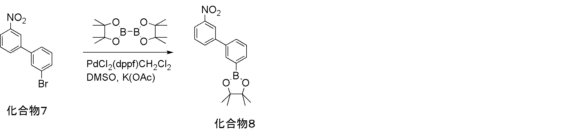
純水を滴下して反応液を減圧濾過し、濾液がトルエンで抽出し、無水硫酸マグネシウムで乾燥して活性白土により粗精製した。更に粗精製品をカラムクロマトグラフィー(展開液:ヘキサン/塩化メチレン=1/1)により精製し、化合物8(19.1g、収率84%)を得た。
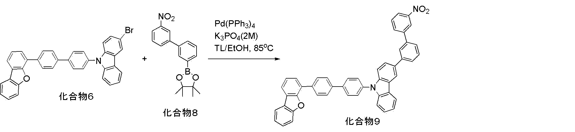
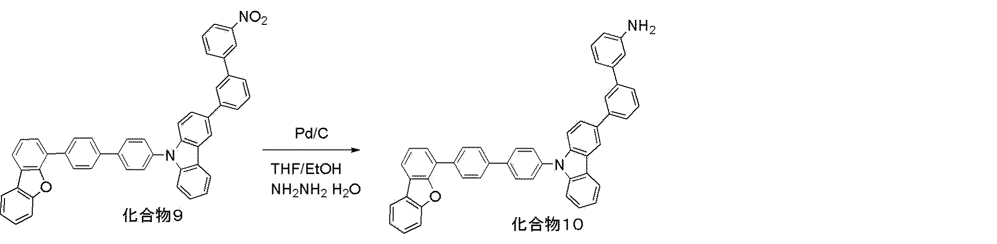
反応液を水湿のセライトで減圧濾過し、濾液を濃縮し、メタノールで洗って精製し、化合物10(3.0g、収率91%)を得た。

ビス(トリフェニルホスフィン)パラジウム(II)ジクロリド(0.033g、0.046mmol)を加え、65℃で3時間攪拌した。反応液に水を加え、トルエンで抽出を行った。有機層を無水硫酸マグネシウムで乾燥して活性白土より粗精製した。粗精製品をカラムクロマトグラフィー(展開液:ヘキサン/塩化メチレン=85/15)により精製し、化合物12(4.1g、収率90.3%)を得た。

反応液を減圧濾過し、濾液がトルエンで抽出し、無水硫酸マグネシウムで乾燥して活性白土により粗精製した。更に粗精製品をカラムクロマトグラフィー(展開液:ヘキサン/酢酸エチル=90/10)により精製し、化合物13(4.5g、収率97%)を得た。
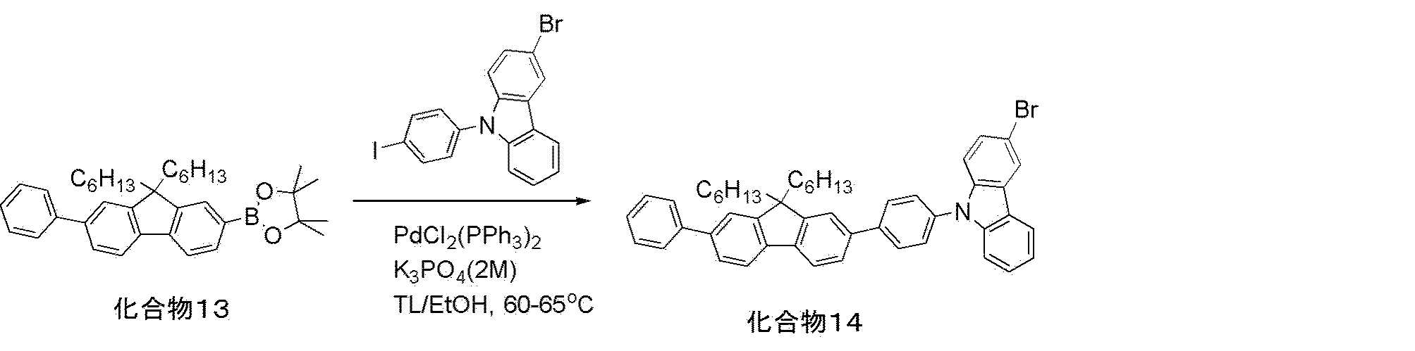
ビス(トリフェニルホスフィン)パラジウム(II)ジクロリド(0.030g、0.042mmol)を加え、65℃で3時間攪拌した。反応液に水を加え、トルエンで抽出を行った。有機層を無水硫酸マグネシウムで乾燥して活性白土より粗精製した。粗精製品をカラムクロマトグラフィー(展開液:ヘキサン/塩化メチレン=75/25)により精製し、化合物14(2.2g、収率35.9%)を得た。

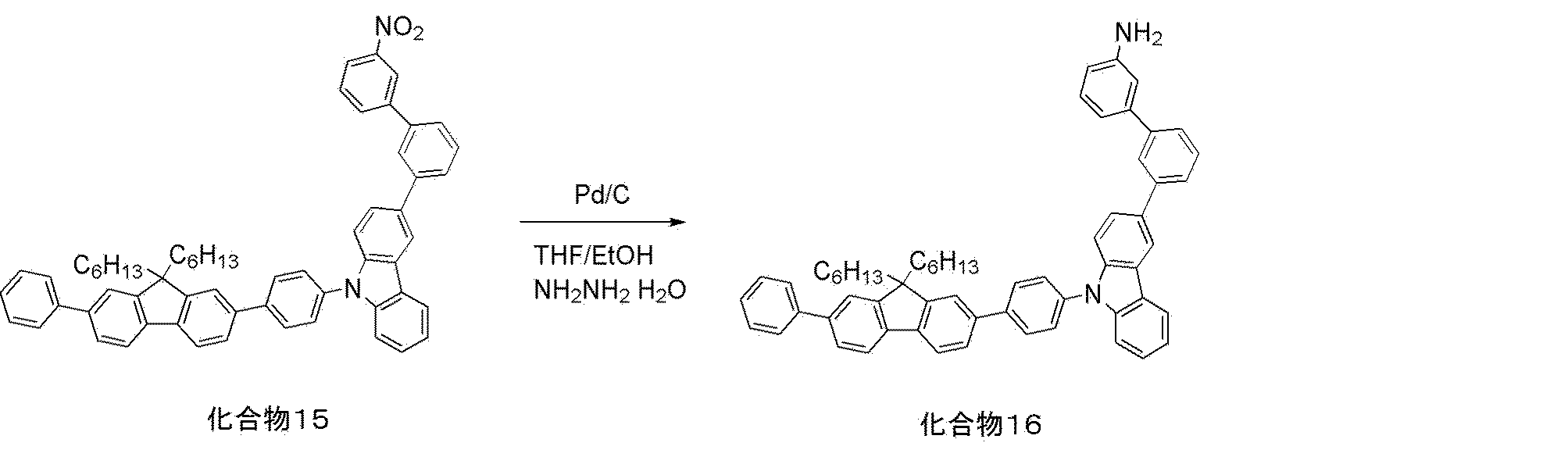
反応液を水湿のセライトで減圧濾過し、濾液を濃縮し、エタノールで再結晶により精製し、化合物16(0.9g、収率53.3%)を得た。




窒素気流下、化合物21(17.8g、33.0mmol)、4-(9H-カルバゾール-9-イル)フェニルボロン酸(9.5g、33.0mmol)、リン酸カリウム(21.0g、99.0mmol)、トルエン(100ml)、エタノール(50ml)及び水(50ml)をフラスコに仕込み、系内を十分に窒素置換して65℃まで加温した。
ビス(トリフェニルホスフィン)パラジウム(II)ジクロリド(0.12g、0.17mmol)を加え、65℃で3時間攪拌した。反応液に水を加え、トルエンで抽出を行った。有機層を無水硫酸マグネシウムで乾燥して活性白土より粗精製した。粗精製品をカラムクロマトグラフィー(展開液:ヘキサン/塩化メチレン=80/20)により精製し、化合物22(18.4g、収率85.2%)を得た。

反応液を減圧濾過し、濾液がトルエンで抽出し、無水硫酸マグネシウムで乾燥して活性白土により粗精製した。更に粗精製品をカラムクロマトグラフィー(展開液:ヘキサン/酢酸エチル=90/10)により精製し、化合物23(17.7g、収率90.7%)を得た。
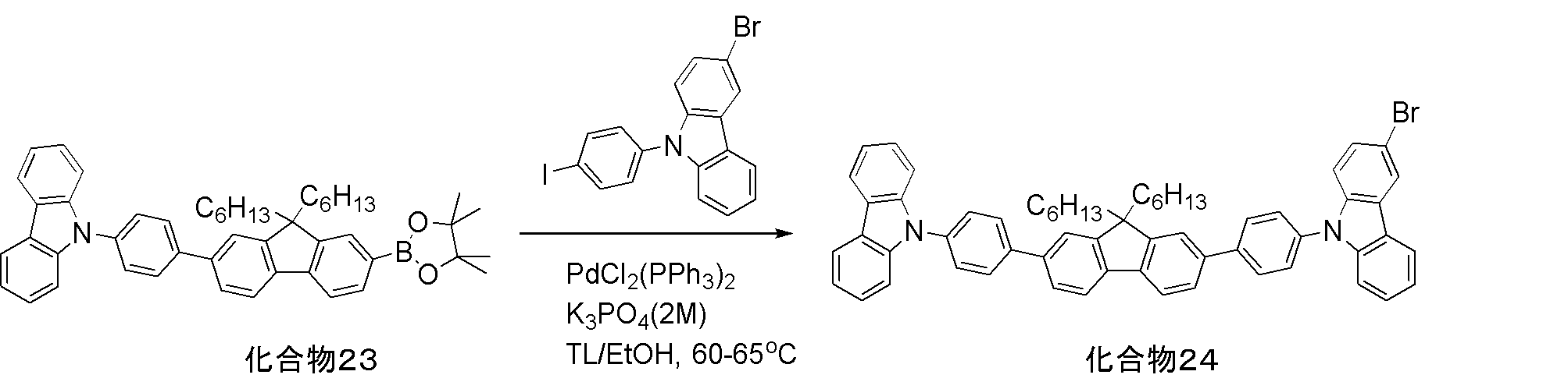
ビス(トリフェニルホスフィン)パラジウム(II)ジクロリド(0.052g、0.073mmol)を加え、65℃で3時間攪拌した。反応液に水を加え、トルエンで抽出を行った。有機層を無水硫酸マグネシウムで乾燥して活性白土より粗精製した。粗精製品をカラムクロマトグラフィー(展開液:ヘキサン/塩化メチレン=75/25)により精製し、化合物24(4.8g、収率76.0%)を得た。
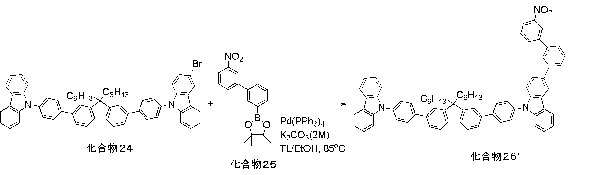
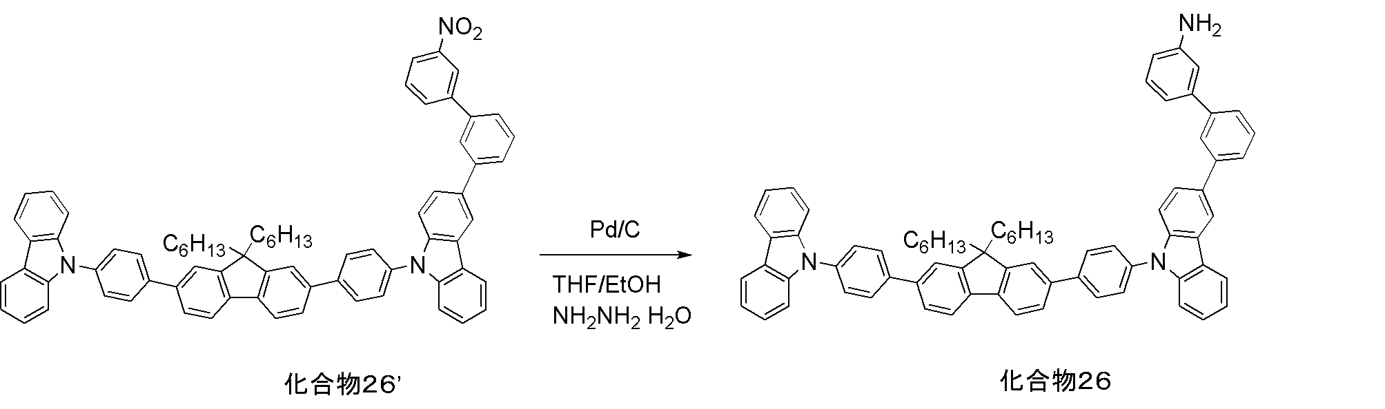
反応液を水湿のセライトで減圧濾過し、濾液を濃縮し、エタノールで再結晶により精製し、化合物26(3.3g、収率87.2%)を得た。

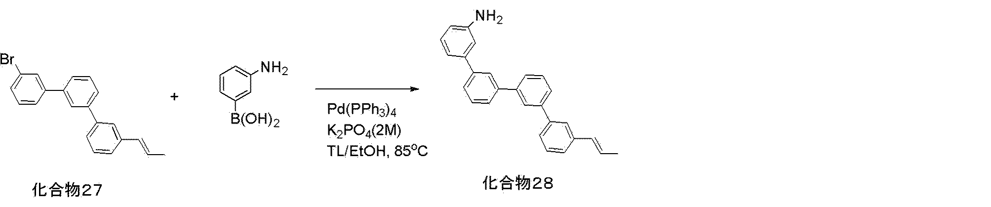

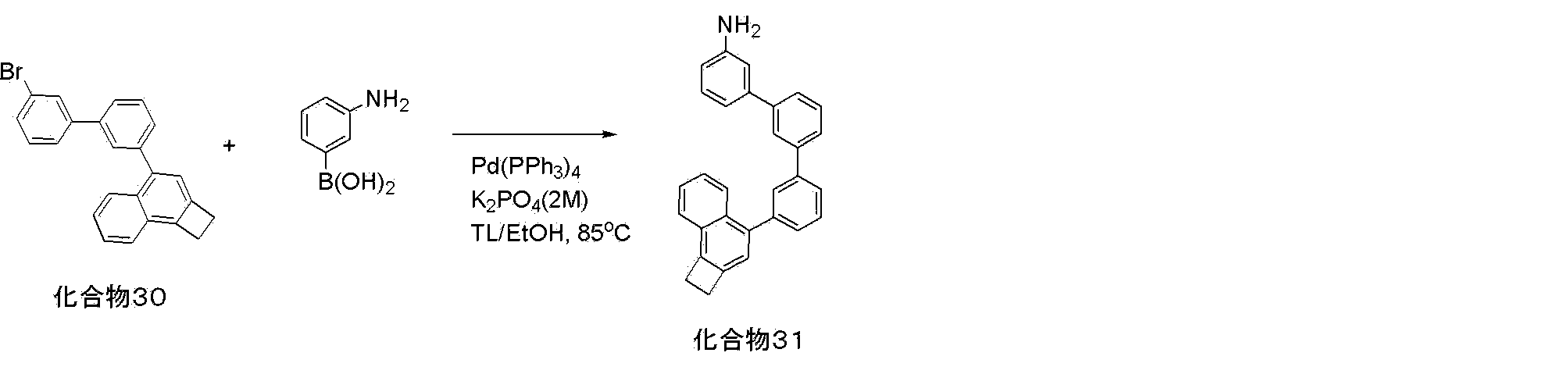
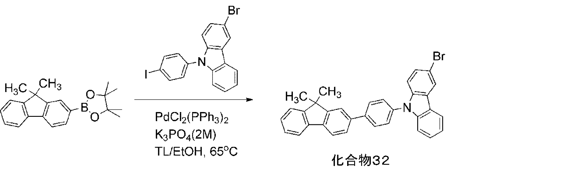
ビス(トリフェニルホスフィン)パラジウム(II)ジクロリド(0.030g、0.042mmol)を加え、65℃で3時間攪拌した。反応液に水を加え、トルエンで抽出を行った。有機層を無水硫酸マグネシウムで乾燥して活性白土より粗精製した。粗精製品をカラムクロマトグラフィー(展開液:ヘキサン/塩化メチレン=75/25)により精製し、化合物32(2.2g、収率35.9%)を得た。
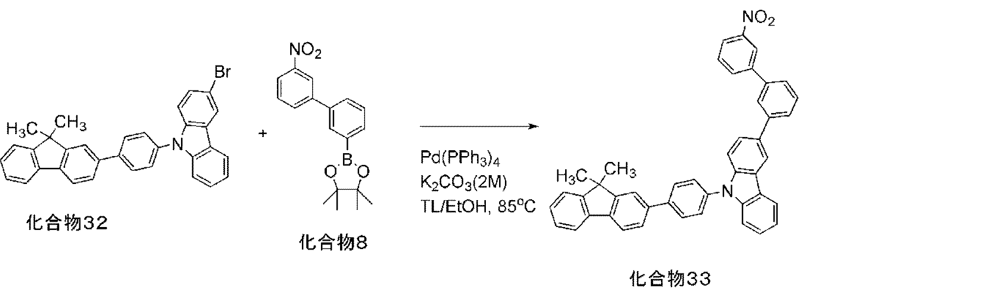

反応液を水湿のセライトで減圧濾過し、濾液を濃縮し、エタノールで再結晶により精製し、化合物34(0.9g、収率53.3%)を得た。

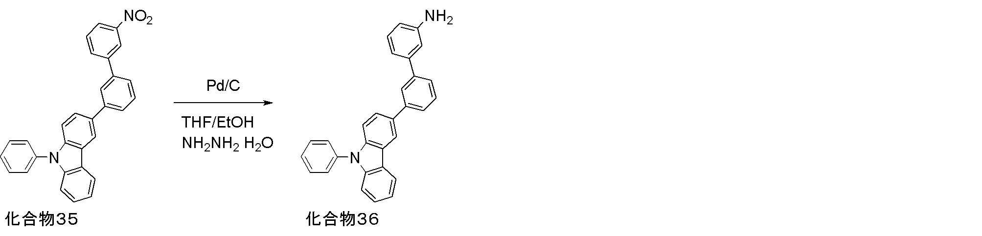
反応液を水湿のセライトで減圧濾過し、濾液を濃縮し、メタノールで洗って精製し、化合物36(3.0g、収率91%)を得た。
[重合体1の合成]
以下の反応式に従い、重合体1を合成した。
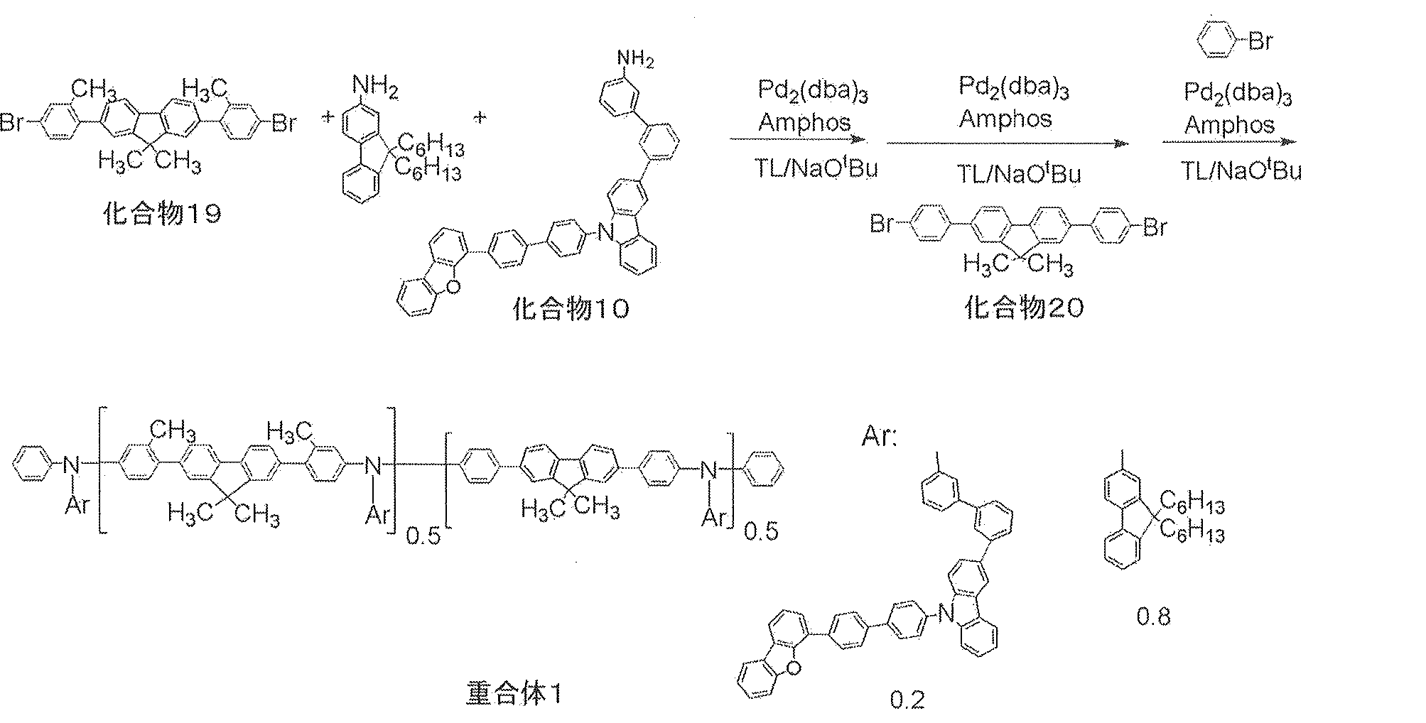
トリス(ジベンジリデンアセトン)ジパラジウム錯体(0.062g、0.07mmol)のトルエン11ml溶液に、[4-(N,N-ジメチルアミノ)フェニル]ジ-tert-ブチルホスフィン(Amphos)(0.14g、0.5mmol)を加え、60℃まで加温した(溶液B1)。
重量平均分子量(Mw)=40000
数平均分子量(Mn)=29850
分散度(Mw/Mn)=1.34
[重合体2の合成]
以下の反応式に従い、重合体2を合成した。
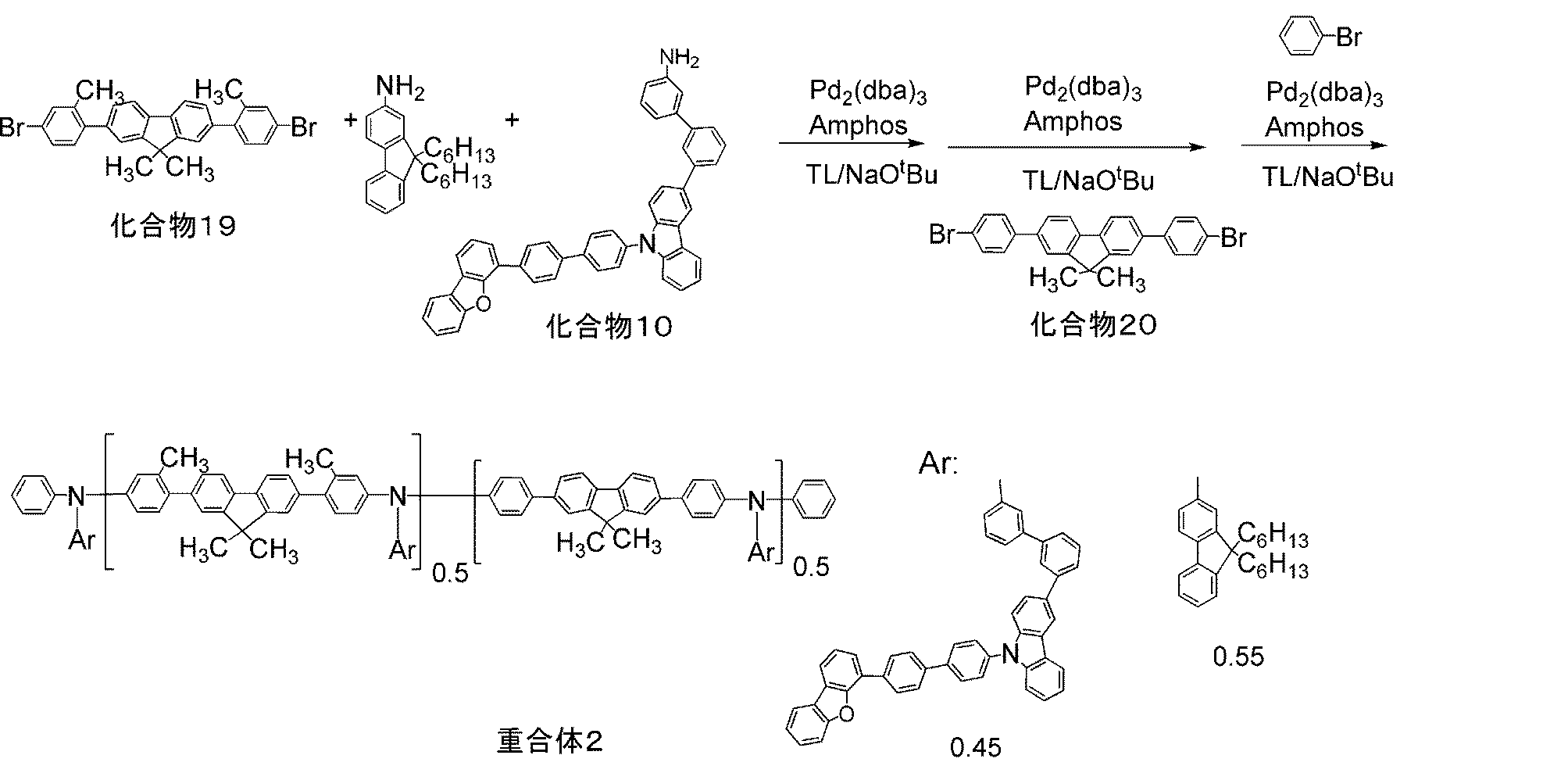
重量平均分子量(Mw)=39000
数平均分子量(Mn)=27080
分散度(Mw/Mn)=1.44
[重合体3の合成]
以下の反応式に従い、重合体3を合成した。

重量平均分子量(Mw)=19500
数平均分子量(Mn)=14770
分散度(Mw/Mn)=1.32
[重合体4の合成]
以下の反応式に従い、重合体4を合成した。
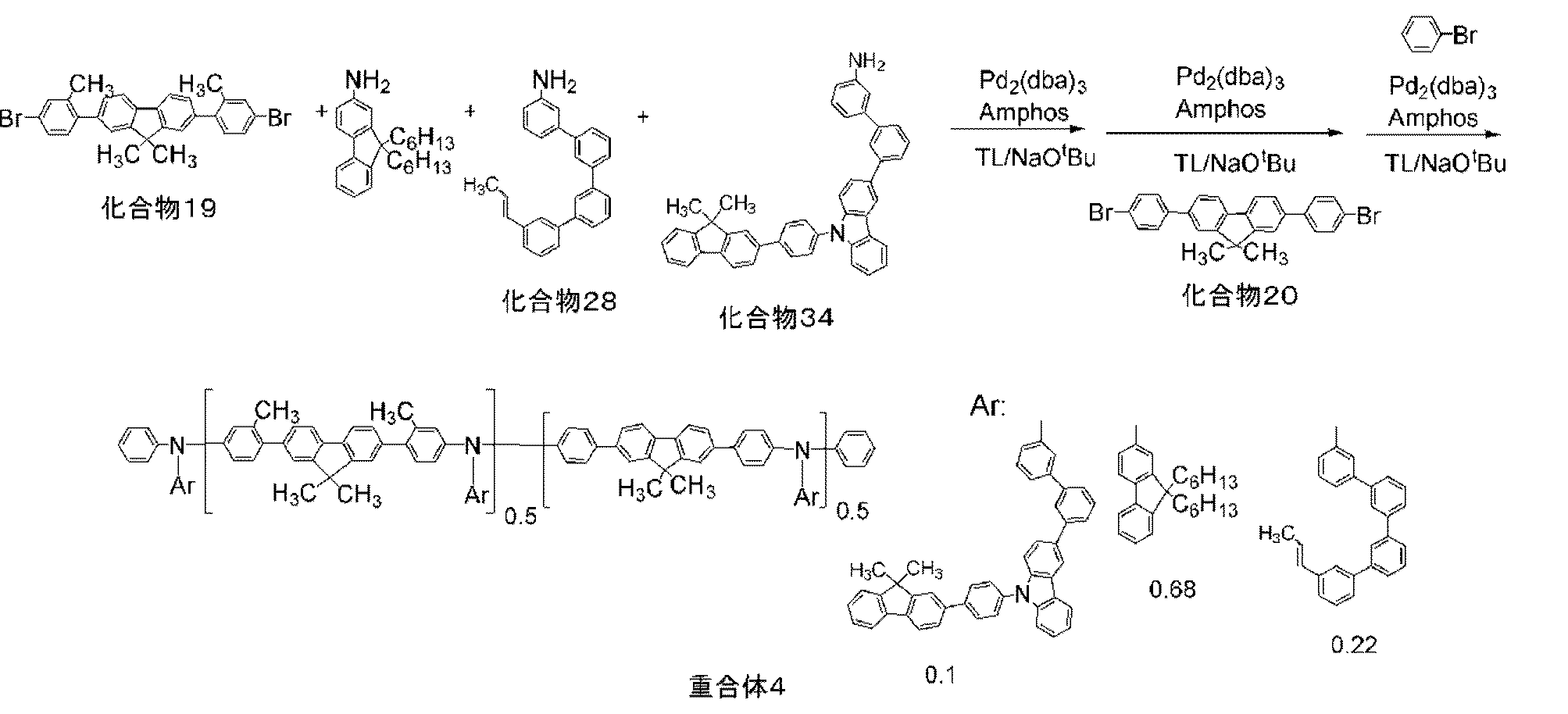
トリス(ジベンジリデンアセトン)ジパラジウム錯体(0.069g、0.075mmol)のトルエン11.9ml溶液に、[4-(N,N-ジメチルアミノ)フェニル]ジ-tert-ブチルホスフィン(Amphos)(0.16g、0.6mmol)を加え、60℃まで加温した(溶液B4)。
数平均分子量(Mn)=11100
分散度(Mw/Mn)=1.36
[重合体5の合成]
以下の反応式に従い、重合体5を合成した。
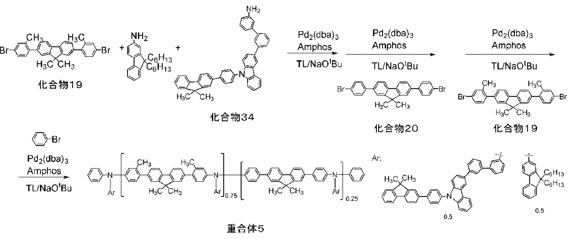
トリス(ジベンジリデンアセトン)ジパラジウム錯体(0.059g、0.06mmol)のトルエン10ml溶液に、[4-(N,N-ジメチルアミノ)フェニル]ジ-tert-ブチルホスフィン(Amphos)(0.136g、0.51mmol)を加え、60℃まで加温した(溶液B5)。
重量平均分子量(Mw)=38840
数平均分子量(Mn)=28990
分散度(Mw/Mn)=1.34
実施例で調製した重合体を用いて、シクロヘキシルベンゼン、安息香酸ブチルに対する不溶化実験を行った。重合体1、2及び5をアニソールに溶解し塗布組成物を調製した。塗布組成物を用いてスライドガラス基板上でスピンコートにより110nm~130nmの膜を作製した。さらに、該膜を230℃、30分間熱処理した。その後、室温でそれぞれの膜の厚みを測定した。
さらに、それぞれの膜をシクロヘキシルベンゼンまたは安息香酸ブチルでリンス処理した。リンス処理は、溶媒130μlを塗布膜上に滴下して90秒静置した後、基板をスピンして実施した。リンス処理した膜をスライドガラス基板ごと加熱処理し、スライドガラス基板上の残留膜の膜厚を測定した。リンス処理前後の膜厚の比率(不溶化率)を表1に示した。
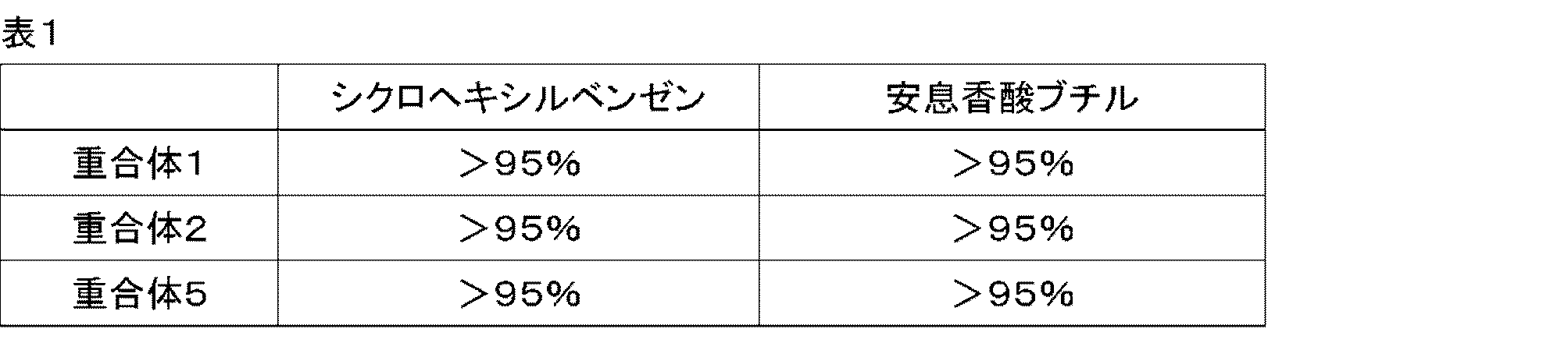
<実施例6>
[重合体6の合成]
以下の反応式に従い、重合体6を合成した。
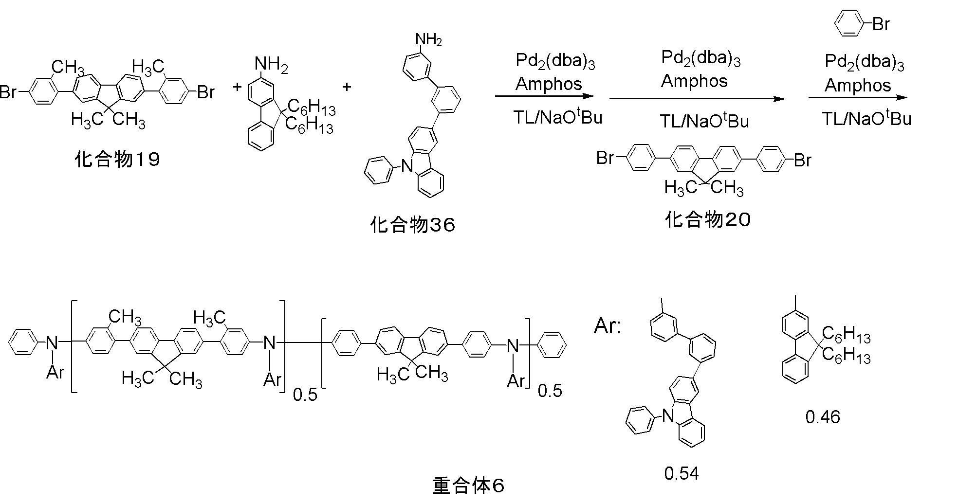
トリス(ジベンジリデンアセトン)ジパラジウム錯体(0.045g、0.05mmol)のトルエン7ml溶液に、[4-(N,N-ジメチルアミノ)フェニル]ジ-tert-ブチルホスフィン(Amphos)(0.11g、0.42mmol)を加え、60℃まで加温した(溶液B6)。
重量平均分子量(Mw)=41300
数平均分子量(Mn)=30150
分散度(Mw/Mn)=1.37
[重合体7の合成]
以下の反応式に従い、重合体7を合成した。
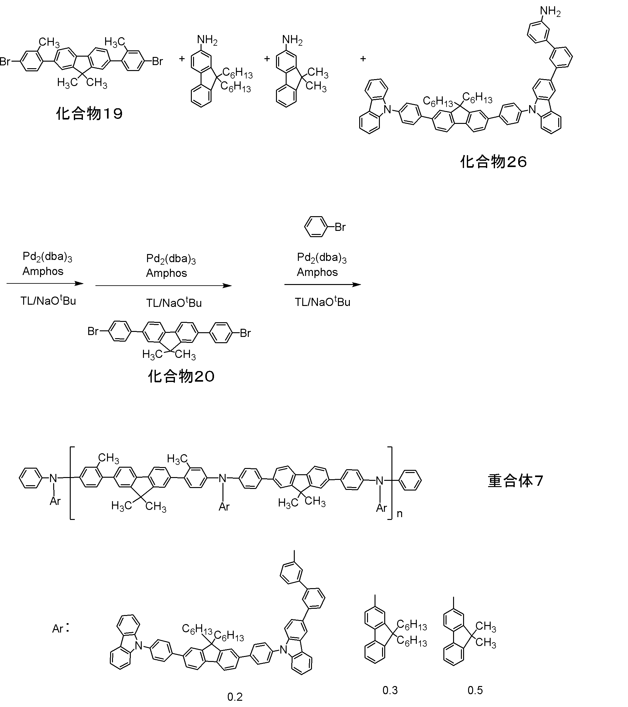
トリス(ジベンジリデンアセトン)ジパラジウム錯体(0.052g、0.06mmol)のトルエン3.3ml溶液に、[4-(N,N-ジメチルアミノ)フェニル]ジ-tert-ブチルホスフィン(Amphos)(0.12g、0.5mmol)を加え、60℃まで加温した(溶液B3)。
窒素気流中、溶液A3に溶液B3を添加し、1.0時間、加熱還流反応した。化合物19が消失したことを確認し、化合物20(1.30g、2.6mmol)を添加した。2時間加熱還流後、ブロモベンゼン(0.44g、2.8mmol)を添加し、2時間加熱還流反応した。反応液を放冷し、トルエン40mlを添加して、エタノール/水(500ml/90ml)溶液に滴下し、エンドキャップした粗ポリマーを得た。
このエンドキャップした粗ポリマーをトルエンに溶解し、アセトンに再沈殿し、析出したポリマーを濾別した。得られたポリマーをトルエンに溶解させ、希塩酸にて洗浄し、アンモニア含有エタノールにて再沈殿した。濾取したポリマーをカラムクロマトグラフィーにより精製し、目的物である重合体7を得た(1.7g)。得られた重合体7の分子量等は以下の通りであった。
数平均分子量(Mn)=29600
分散度(Mw/Mn)=1.35
以下、重合体1、5、6、7および、重合体HT-1を用いて素子を作成しその性能を評価した結果を示す。本発明は以下の実施例に限定されるものではなく、本発明はその要旨を逸脱しない限り任意に変更して実施できる。
有機電界発光素子を以下の方法で作製した。
ガラス基板上にインジウム・スズ酸化物(ITO)透明導電膜を50nmの厚さに堆積したもの(三容真空社製、スパッタ成膜品)を通常のフォトリソグラフィー技術と塩酸エッチングを用いて2mm幅のストライプにパターニングして陽極を形成した。このようにITOをパターン形成した基板を、界面活性剤水溶液による超音波洗浄、超純水による水洗、超純水による超音波洗浄、超純水による水洗の順で洗浄後、圧縮空気で乾燥させ、最後に紫外線オゾン洗浄を行った。
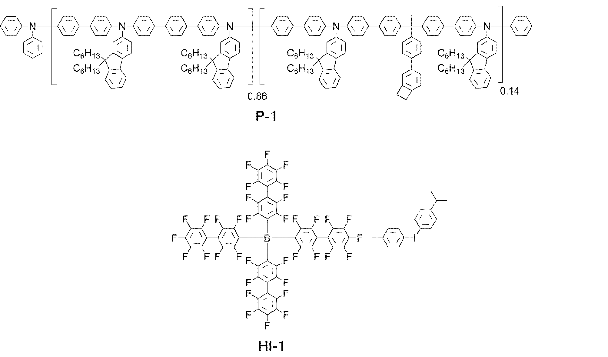
次に、下記の重合体5を有する電荷輸送性高分子化合物100質量部を、シクロヘキシルベンゼンに溶解させ、1.5wt%の溶液を調製した。
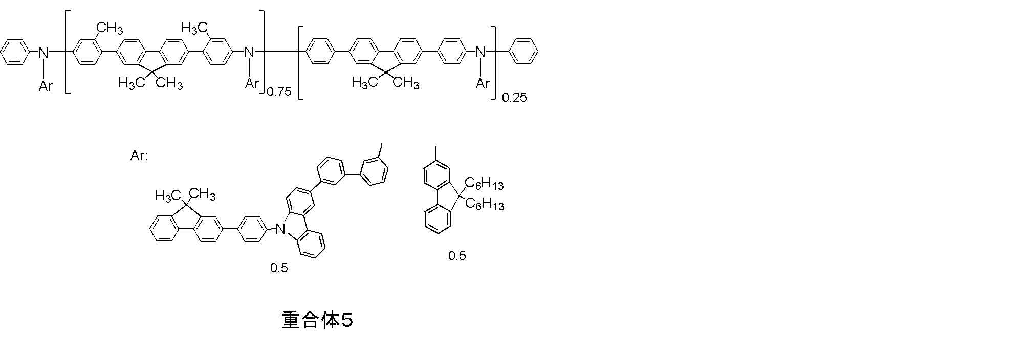
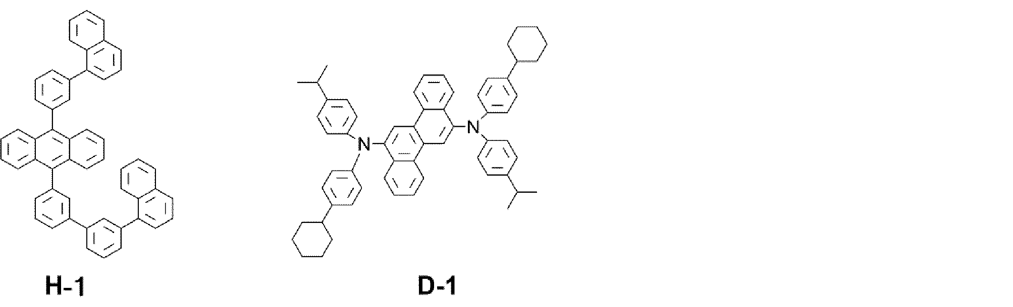
発光層までを成膜した基板を真空蒸着装置に設置し、装置内を2×10⁻⁴Pa以下になるまで排気した。
次に、下記の構造式(HB-1)および8-ヒドロキシキノリノラトリチウムを2:3の膜厚比で、発光層上に真空蒸着法にて1Å/秒の速度で共蒸着し、膜厚30nmの正孔阻止層を形成した。
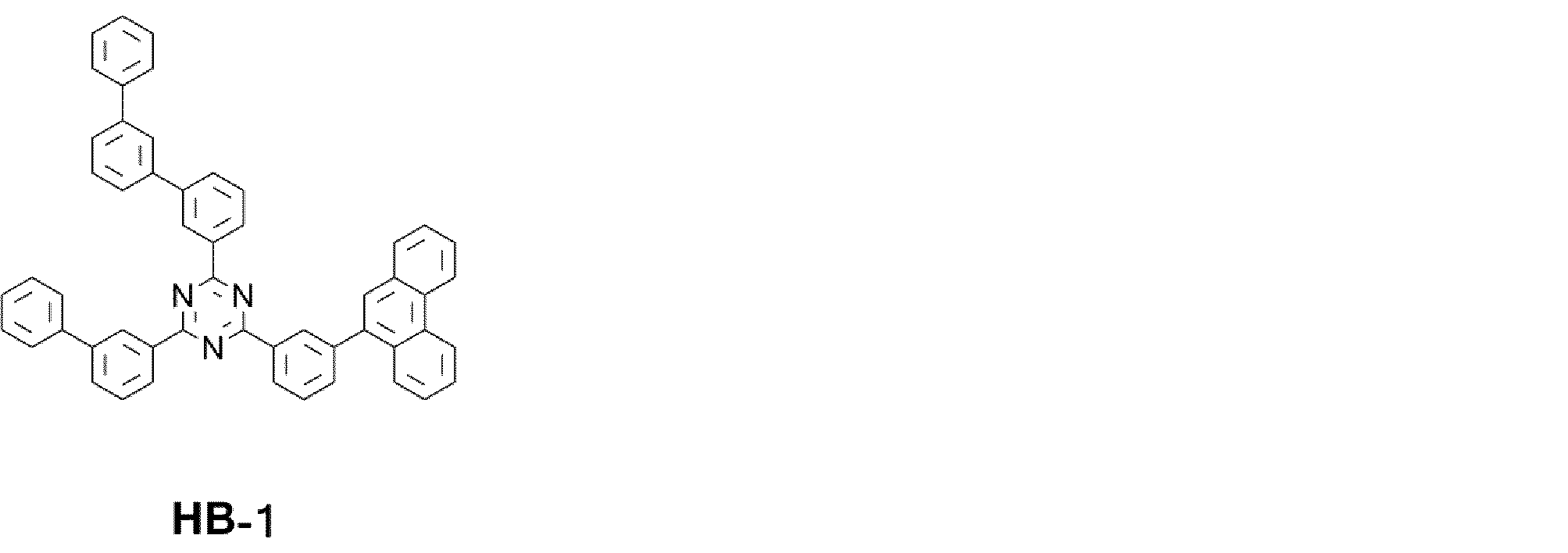
正孔輸送層を、重合体1としたこと以外は、実施例1と同様にして素子を作製した。

正孔輸送層を、(HT-1)としたこと以外は、実施例1と同様にして素子を作製した。

得られた実施例1-2、および比較例1の有機電界発光素子の特性を表1にまとめた。相対発光効率は、輝度1000cd/m2で発光させたときの電流発光効率(cd/A)を測定し、比較例の電流発光効率で実施例の電流発光効率を除して相対値を求め、比較例を100としたときの相対値とした。100を超えていることは電流発光効率が高いことを示す。相対電圧は、電流密度10mA/cm2で発光させたときの電圧(V)を測定し、比較例1の電圧を基準としたときの差(V)である。負の値であることは低電圧化していることを示す。本発明の要旨1の重合体を含む正孔輸送層を有する有機電界素子は、比較例の有機電界素子より、効率が向上し、かつ低電圧化することが分かった。
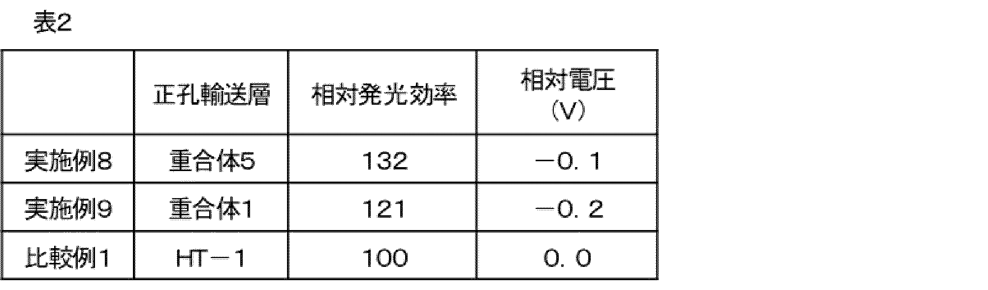
正孔輸送層を重合体5とし、発光層組成を(H-2):(H-3):(D-2)=60:40:15の膜厚75nmの薄膜としたこと以外は、実施例1と同様にして素子を作製した。(H-2)、(H-3)および(D-2)を下記に示す。
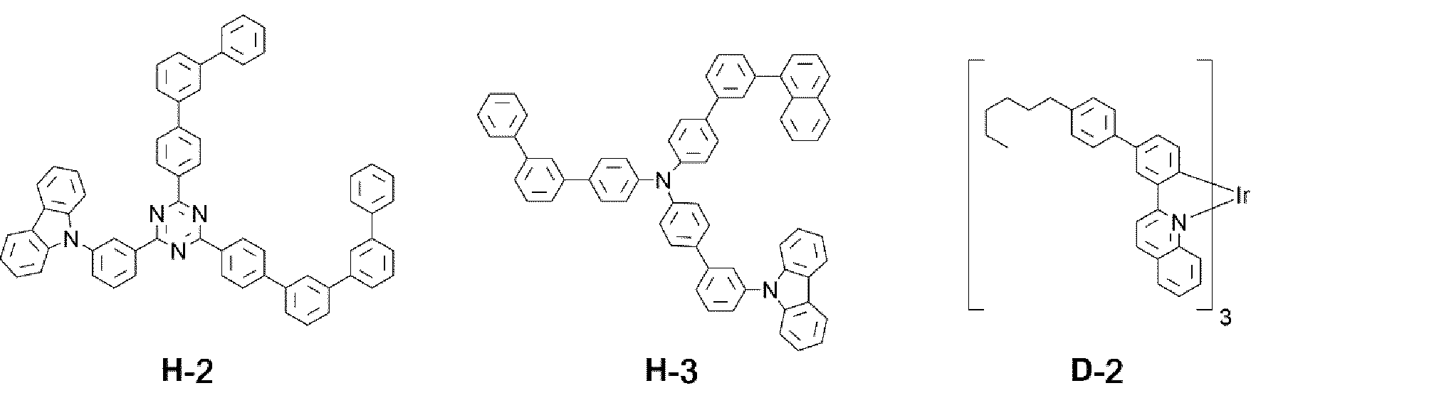
正孔輸送層を(HT-1)としたこと以外は、実施例3と同様にして素子を作製した。
得られた実施例10、および比較例2の有機電界発光素子の特性を表2にまとめた。相対電流効率および相対電圧は、表1と同義である。表2の結果に表すが如く、第2の要旨である、本発明の正孔輸送層および発光層組成を有する有機電界素子は、比較例の有機電界素子より、効率が向上し、かつ低電圧化することが分かった。

正孔注入層を(P1):(HI-1)=100:20の膜厚60nmの薄膜とし、正孔輸送層を重合体5の膜厚25nmの薄膜とし、発光層組成を(H-4):(H-5):(D-2)=60:40:15の膜厚70nmの薄膜としたこと以外は、実施例1と同様にして素子を作製した。(H-4)、(H-5)を下記に示す。
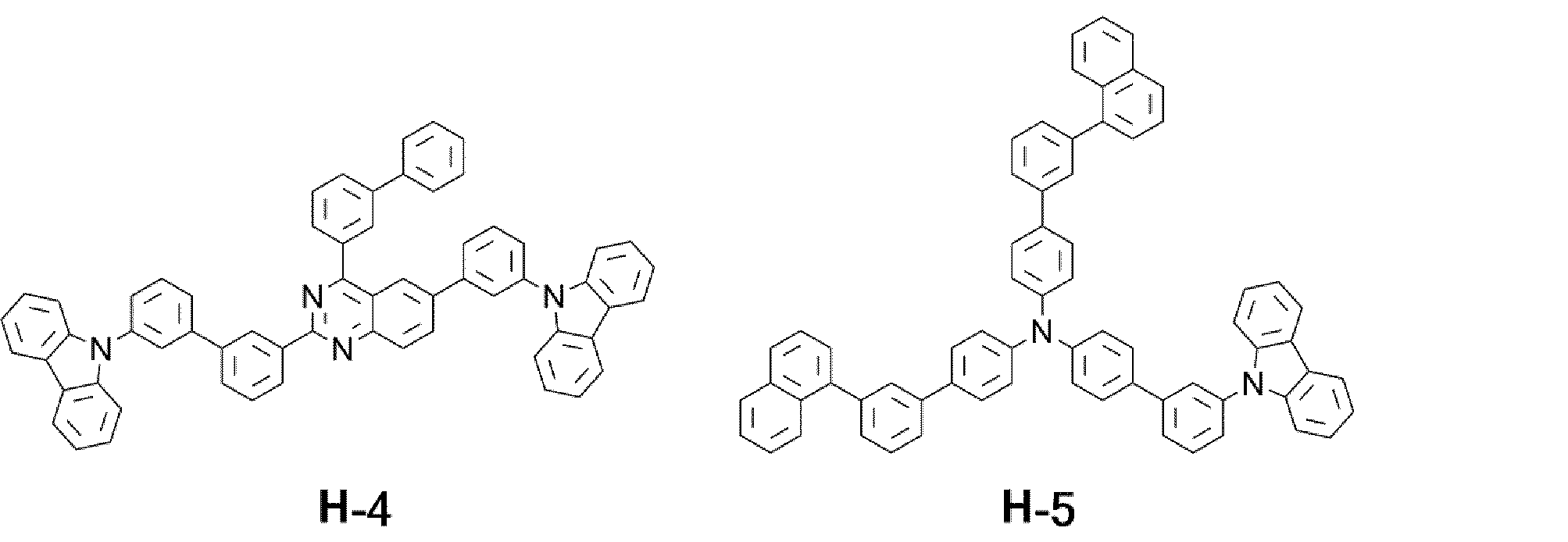
正孔輸送層を重合体6とし、発光層組成を(H-6):(H-7):(D-2)=60:40:15の膜厚70nmの薄膜としたこと以外は、実施例4と同様にして素子を作製した。(H-6)、(H-7)を下記に示す。
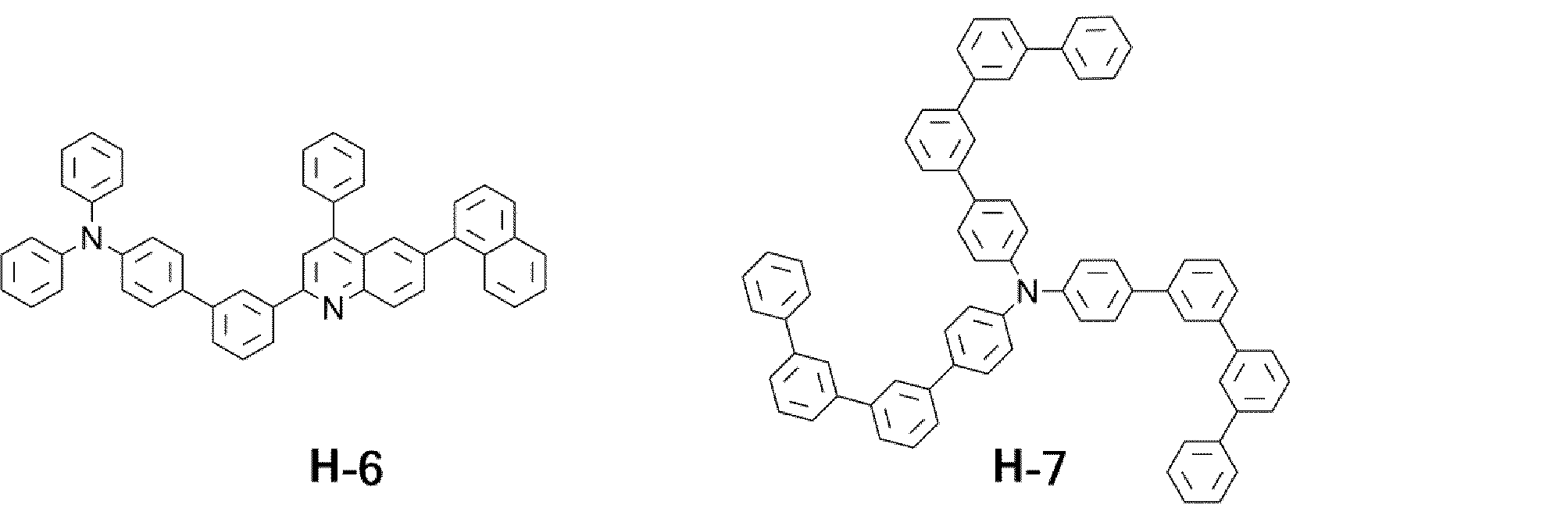
正孔輸送層を重合体6とし、発光層組成を実施例4と同様にしたこと以外は、実施例4と同様にして素子を作製した。
正孔輸送層を重合体5とし、発光層組成を比較例3と同様にしたこと以外は、実施例4と同様にして素子を作製した。
得られた実施例10と参考例1の有機電界発光素子の特性を表3にまとめた。相対電流効率は、輝度1000cd/m2で発光させたときの電流効率(cd/A)を測定し、参考例1を100としたときの相対値とした。相対電圧は、電流密度10mA/cm2で発光させたときの電圧(V)を測定し、参考例1の電圧を基準としたときの差(V)とした。表3の結果に表すが如く、本発明の第1の要旨である重合体を正孔輸送層に含む有機電界素子は、効率が向上することが分かった。
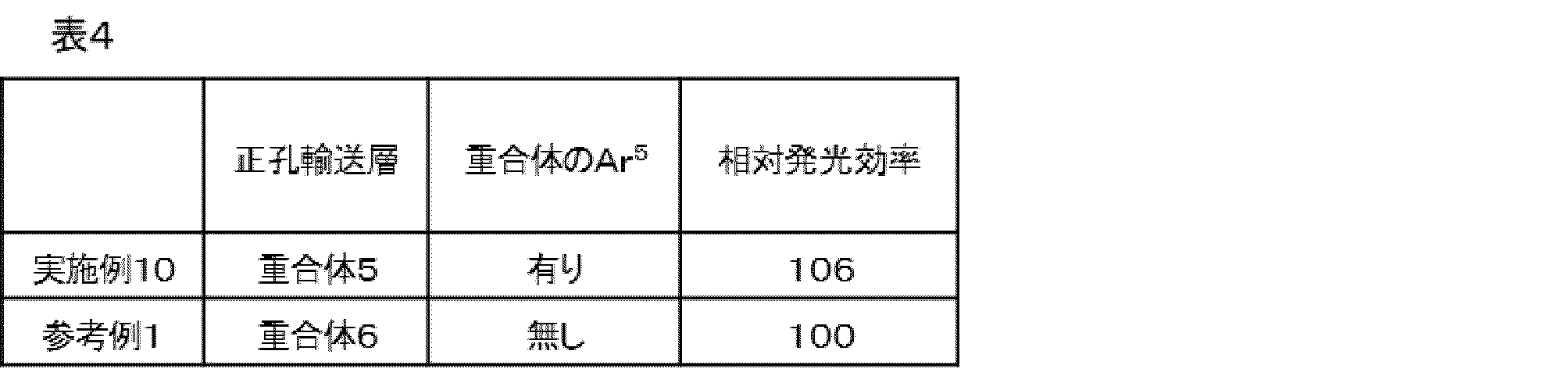
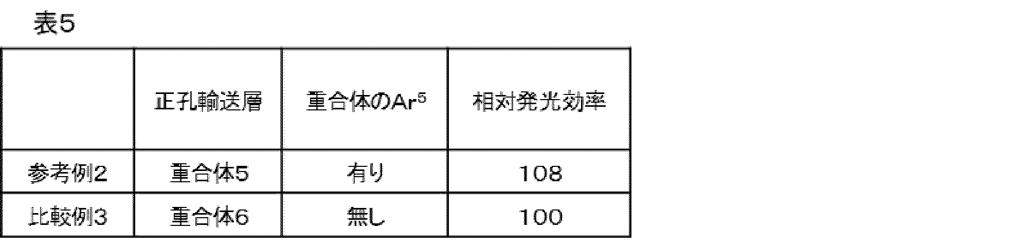
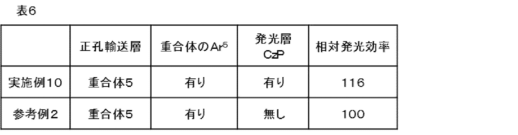

[重合体8の合成]
以下の反応式に従い、重合体8を合成した。

重量平均分子量(Mw)=39800
数平均分子量(Mn)=29920
分散度(Mw/Mn)=1.33
各重合体1と重合体8を2-メチルテトラヒドロフランに溶解させて濃度1重量%溶液を調製した。この溶液試料を蛍光分光光度計(日立 蛍光分光光度計F-4500)で励起波長350nm、液体窒素による冷却条件下で蛍光発光スペクトルおよびリン光発光スペクトルを測定した。得られた蛍光発光スペクトル、リン光発光スペクトルにおいて最も短波長側にある発光ピークのピークトップ波長からS1準位、T1準位を得た。測定結果を表2に示す。
Ar5の末端がカルバゾールである重合体8よりもカルバゾールでない重合体1の方が、T1順位が高い結果となった。これは、カルバゾールが一つの場合、2つのカルバゾール同士が共役している場合と比較して共役長が短くなることにより、分子のエネルギーキャップが広くなり、T1レベルが高くなると考えられる。T1が高いことで、発光層からのエネルギーが正孔輸送層に移りにくく、発光効率が高い有機EL素子を実現できると考えられる。
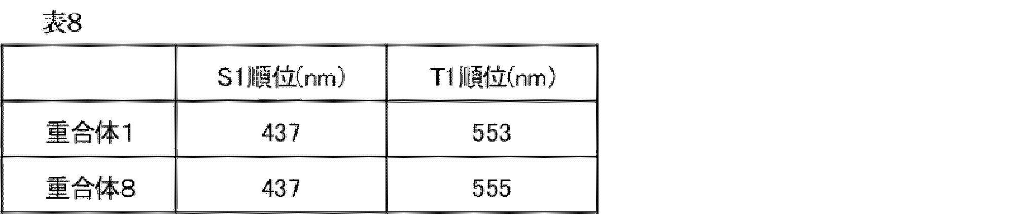
計算により、以下重合体ユニット1~5の電子状態を確認した。
電子状態の計算には、ソフトウェアGaussian 09, Revision B.01,(下記※参照)を用いた。その際、量子化学計算法として、密度汎関数法(Density Functional Theory)を採用し、汎関数にはB3LYPを用い、基底関数としては6-31Gを用いて基底状態の構造最適化計算を実施した。HOMO、LUMOの表示(関数値0.03 a.u.)にはソフトウェア MolStudio R4.0 Rev 2.0 Pprogram(NEC Corporaion)を利用した。
本計算の結果は、図2~4に示す。図2、3から、重合体ユニット1、2では、HOMOが主鎖のN近傍に存在し、LUMOが側鎖の末端側に局在していることがわかる。また、図4から、HOMOは、ユニット3~ユニット5いずれも主鎖のN近傍に存在しており、LUMOは、式(1)のAr5が存在し、環が多いほど、カルバゾール環よりもより末端側に分布し、局在化することがわかる。
M.J.Frisch, G.W.Trucks, H.B.Schlegel, G.E.Scuseria, M.A.Robb, J.R.Cheeseman, G.Scalmani, V.Barone, B.Mennucci, G.A.Petersson, H.Nakatsuji, M.Caricato, X.Li, H.P.Hratchian, A.F.Izmaylov, J.Bloino, G.Zheng, J.L.Sonnenberg, M.Hada, M.Ehara, K.Toyota, R.Fukuda, J.Hasegawa, M.Ishida, T.Nakajima, Y.Honda, O.Kitao, H.Nakai, T.Vreven, J.A.Montgomery,Jr., J.E.Peralta, F.Ogliaro, M.Bearpark, J.J.Heyd, E.Brothers, K.N.Kudin, V.N.Staroverov, T.Keith, R.Kobayashi, J.Normand, K.Raghavachari, A.Rendell, J.C.Burant, S.S.Iyengar, J.Tomasi, M.Cossi, N.Rega, J.M.Millam, M.Klene, J.E.Knox, J.B.Cross, V.Bakken, C.Adamo, J.Jaramillo, R.Gomperts, R.E.Stratmann, O.Yazyev, A.J.Austin, R.Cammi, C.Pomelli, J.W.Ochterski, R.L.Martin, K.Morokuma, V.G.Zakrzewski, G.A.Voth, P.Salvador, J.J.Dannenberg, S.Dapprich, A.D.Daniels, O.Farkas, J.B.Foresman, J.V.Ortiz, J.Cioslowski, and D.J.Fox, Gaussian, Inc., Wallingford CT, 2010.
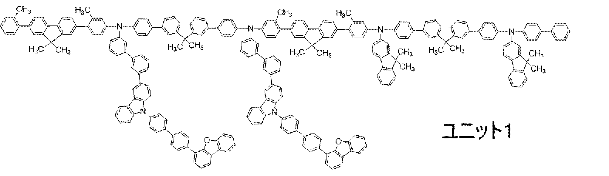
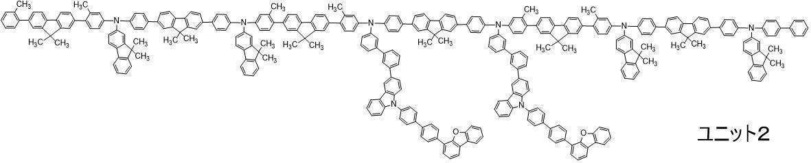
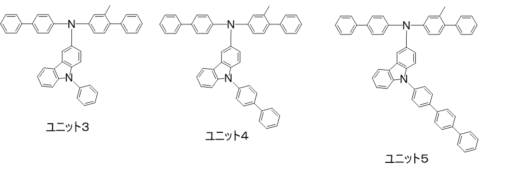
<実施例13>
有機電界発光素子を以下の方法で作製した。
ガラス基板上にインジウム・スズ酸化物(ITO)透明導電膜を130nmの厚さに堆積したもの(三容真空社製、スパッタ成膜品)を通常のフォトリソグラフィー技術と塩酸エッチングを用いて2mm幅のストライプにパターニングして陽極を形成した。このようにITOをパターン形成した基板を、界面活性剤水溶液による超音波洗浄、超純水による水洗、超純水による超音波洗浄、超純水による水洗の順で洗浄後、圧縮空気で乾燥させ、最後に紫外線オゾン洗浄を行った。

次に、重合体7である電荷輸送性重合体100質量部を、シクロヘキシルベンゼンに溶解させ、3.0wt%の溶液を調製した。
この溶液を、上記正孔注入層を塗布成膜した基板上に窒素グローブボックス中でスピンコートし、窒素グローブボックス中のホットプレートで230℃、30分間乾燥させ、膜厚40nmの均一な薄膜を形成し、正孔輸送層とした。
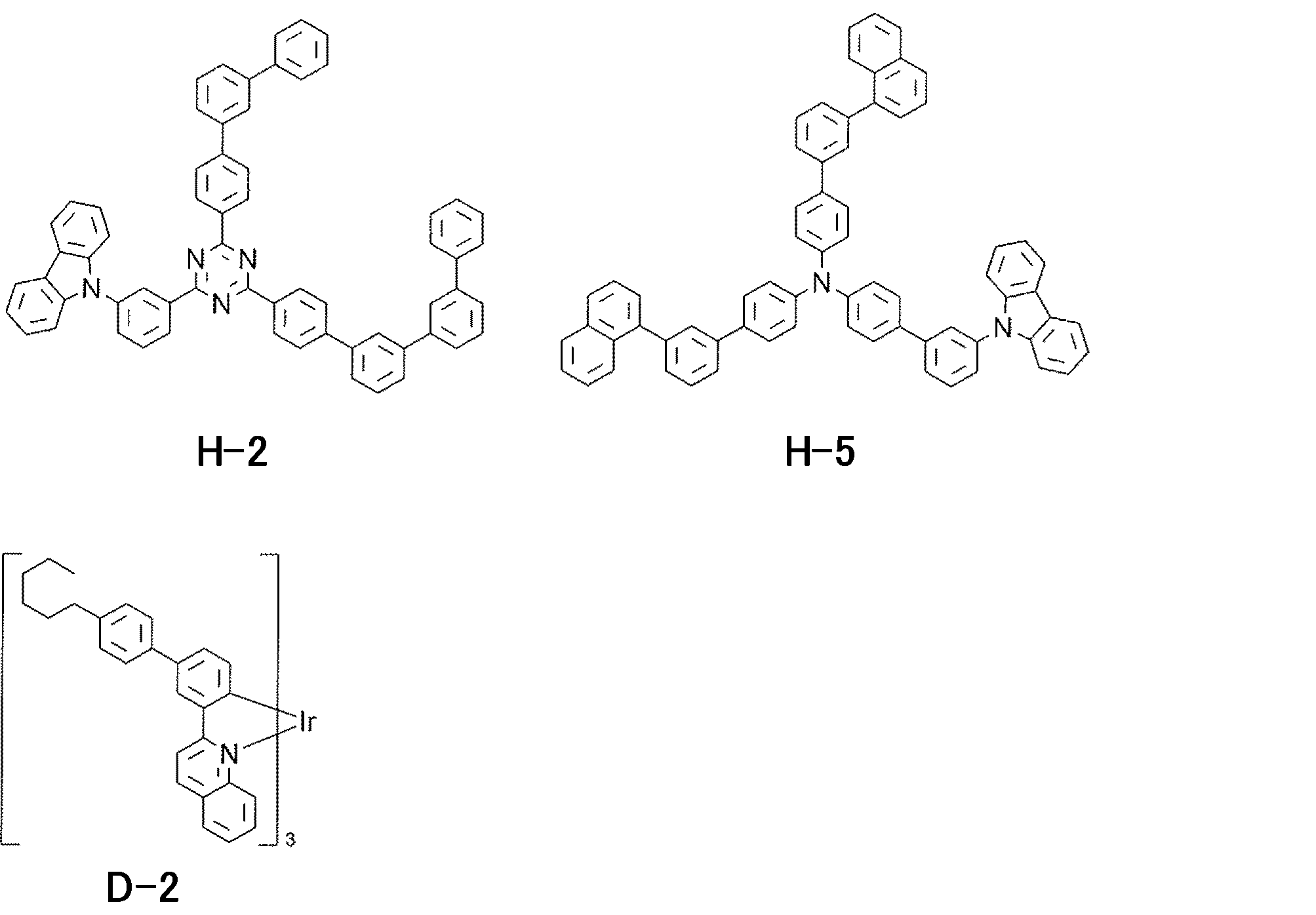
発光層までを成膜した基板を真空蒸着装置に設置し、装置内を2×10⁻⁴Pa以下になるまで排気した。

この素子は、正孔輸送層および発光層に、式(Cz-P)を部分構造として有する材料を含有する。
正孔輸送層化合物を、重合体7からHT-2に変更したこと以外は、実施例13と同様にして素子を作製した。
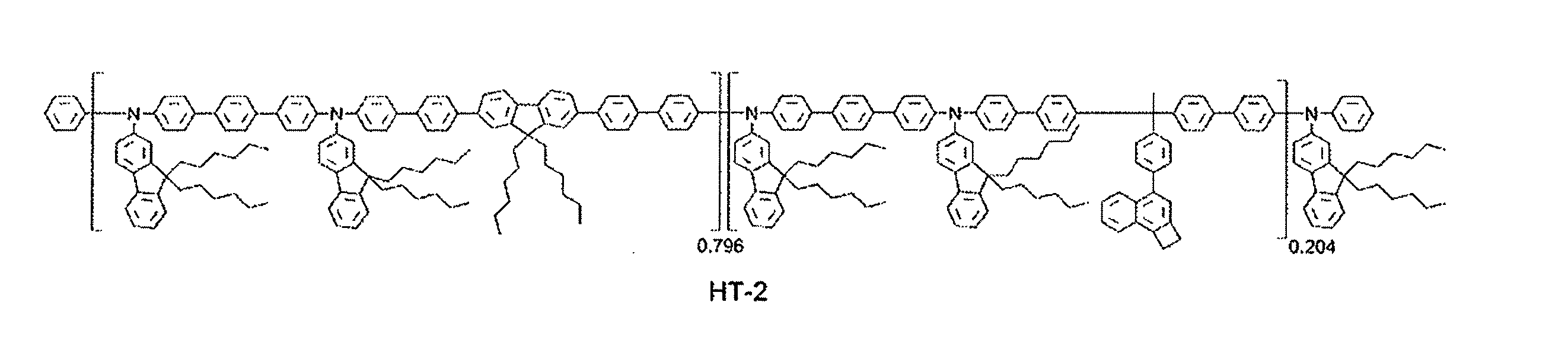
実施例13および比較例4で得られた有機電界発光素子の電圧および駆動寿命の評価を行った結果を表※に示す。電圧は10mA/cm2通電した時の電圧を測定し、比較例4の素子の電圧を基準として実施例13の素子の電圧と比較例4の素子の電圧との差を求め、相対電圧[V]とした。また、素子を40mA/cm2で駆動させ、15%輝度減衰寿命(LT85)を測定し、比較例4の15%減衰寿命を基準として1とした場合の比を相対寿命として求めた。それらを、表7に示す。表7の結果に表すが如く、正孔輸送層(HTL)および発光層(EML)発光層の両方に式(CzP)を部分構造として有する材料を含有する材料を用いた有機電界発光素子では、電圧が低く、寿命が長いことが分かる。

発光層組成を(H-8):(H-5):(D-2)=40:60:20としたこと以外は、実施例13と同様にして素子を作製した。(H-3)の構造式を下記に示す。
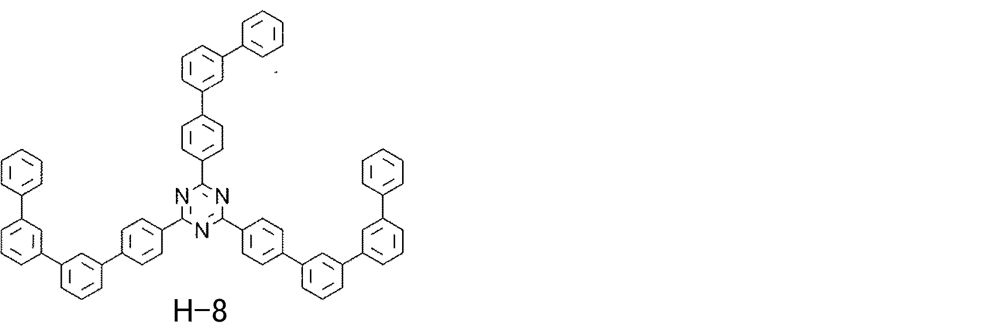
発光層組成を(H-8):(H-9):(D-2)=40:60:20としたこと以外は、実施例13と同様にして素子を作製した。
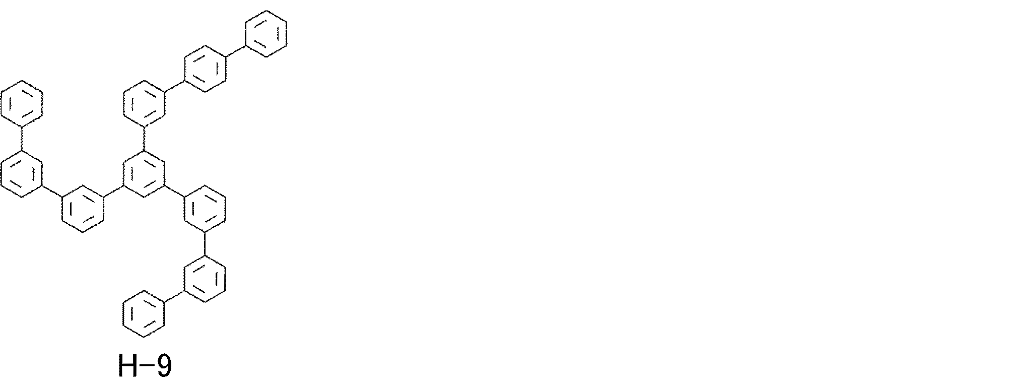
正孔輸送層をHT-2、発光層組成を(H-8):(H-9):(D-2)=40:6
0:20としたこと以外は、実施例13と同様にして素子を作製した。
得られた実施例14、比較例5、および比較例6の有機電界発光素子を、実施例13、比較例4と同様にして相対電圧、相対寿命を求めた。このとき、比較例6を基準とした。それらを、表8に示す。表8の結果に表すが如く、正孔輸送層および発光層の両方に式(CzP)を部分構造として有する材料を含有する材料を用いた有機電界発光素子では、電圧が低く、かつ寿命が長いことが分かる。
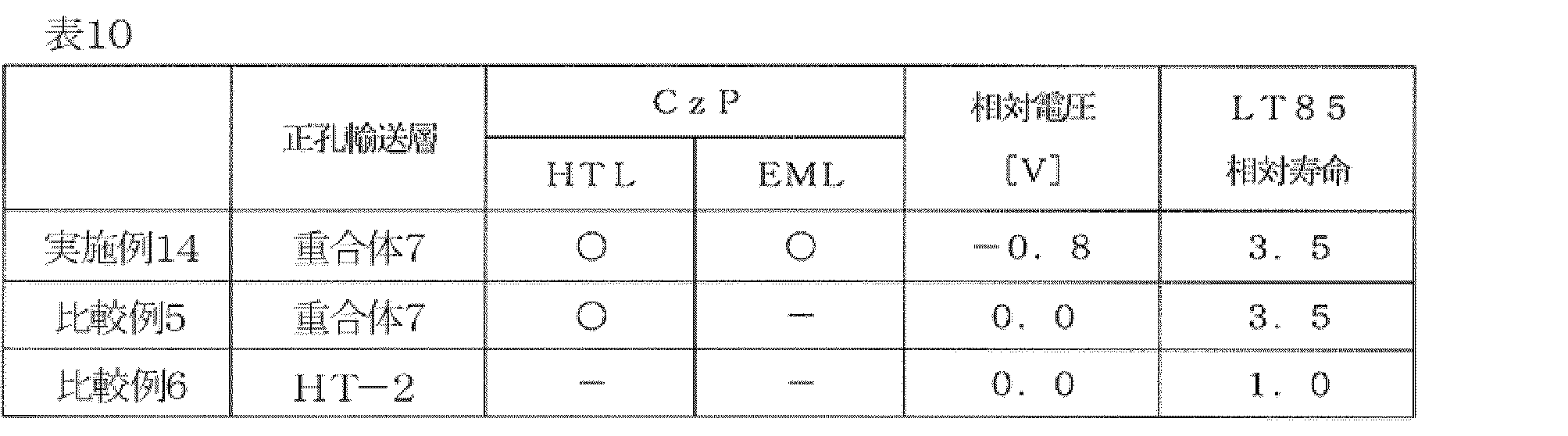
2 陽極
3 正孔注入層
4 正孔輸送層
5 発光層
6 正孔阻止層
7 電子輸送層
8 電子注入層
9 陰極
10 有機電界発光素子
Claims (22)
- 下記式(1)で表される繰り返し単位を含む重合体。

(式(1)中、
Gは置換基を有していてもよい芳香族炭化水素基、置換基を有していてもよい芳香族複素環基、又はC原子、N原子、B原子若しくはP原子を表し、
Ar2~Ar4は、それぞれ独立に、置換基を有していてもよい二価の芳香族炭化水素基、置換基を有していてもよい芳香族複素環基、又は置換基を有していてもよい芳香族炭化水素基若しくは置換基を有していてもよい芳香族複素環基が直接若しくは連結基を介して複数個連結した二価の基を表し、
Ar5は置換基を有していてもよい芳香族炭化水素基、置換基を有していてもよい芳香族複素環基、又は置換基を有していてもよい芳香族炭化水素基及び置換基を有していてもよい芳香族複素環基から選択される基が直接若しくは連結基を介して複数個連結した一価の基を表し、
Ar6は水素原子又は置換基を表す。Ar1中の“-*”が式(1)中Gとの結合位置を表す。) - 前記GはN原子である、請求項1に記載の重合体。
- Ar5は、下記a-1~e-4のいずれかで表される、請求項1又は2に記載の重合体。
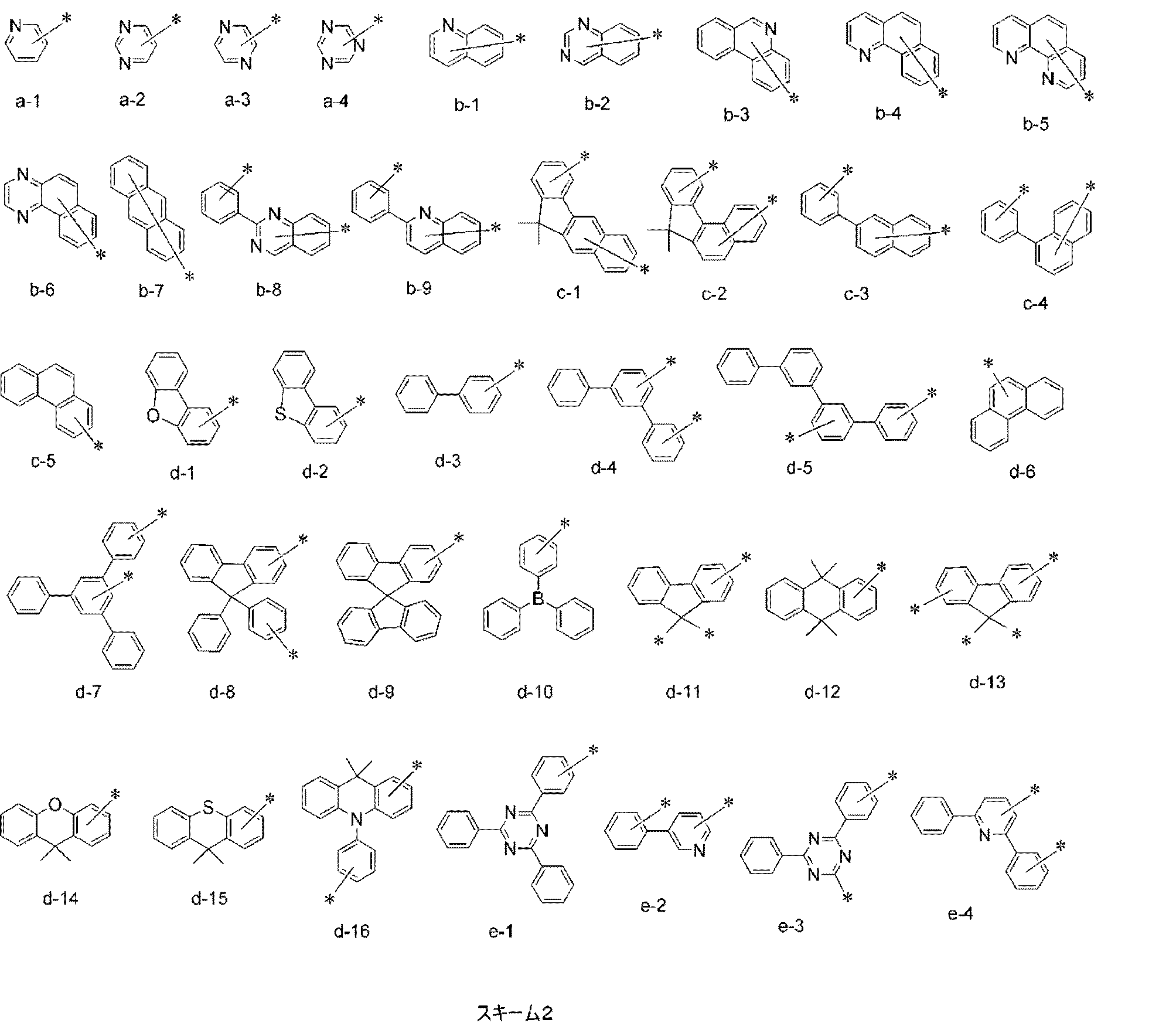
(a-1~e-4において、“-*”はAr4との結合位置を表わし、“-*”が複数ある場合はいずれか一つがAr4との結合位置を表す。) - 前記式(1)が下記式(2)-1~(2)-3のいずれかで表わされる繰り返し単位である、請求項1又は2に記載の重合体。
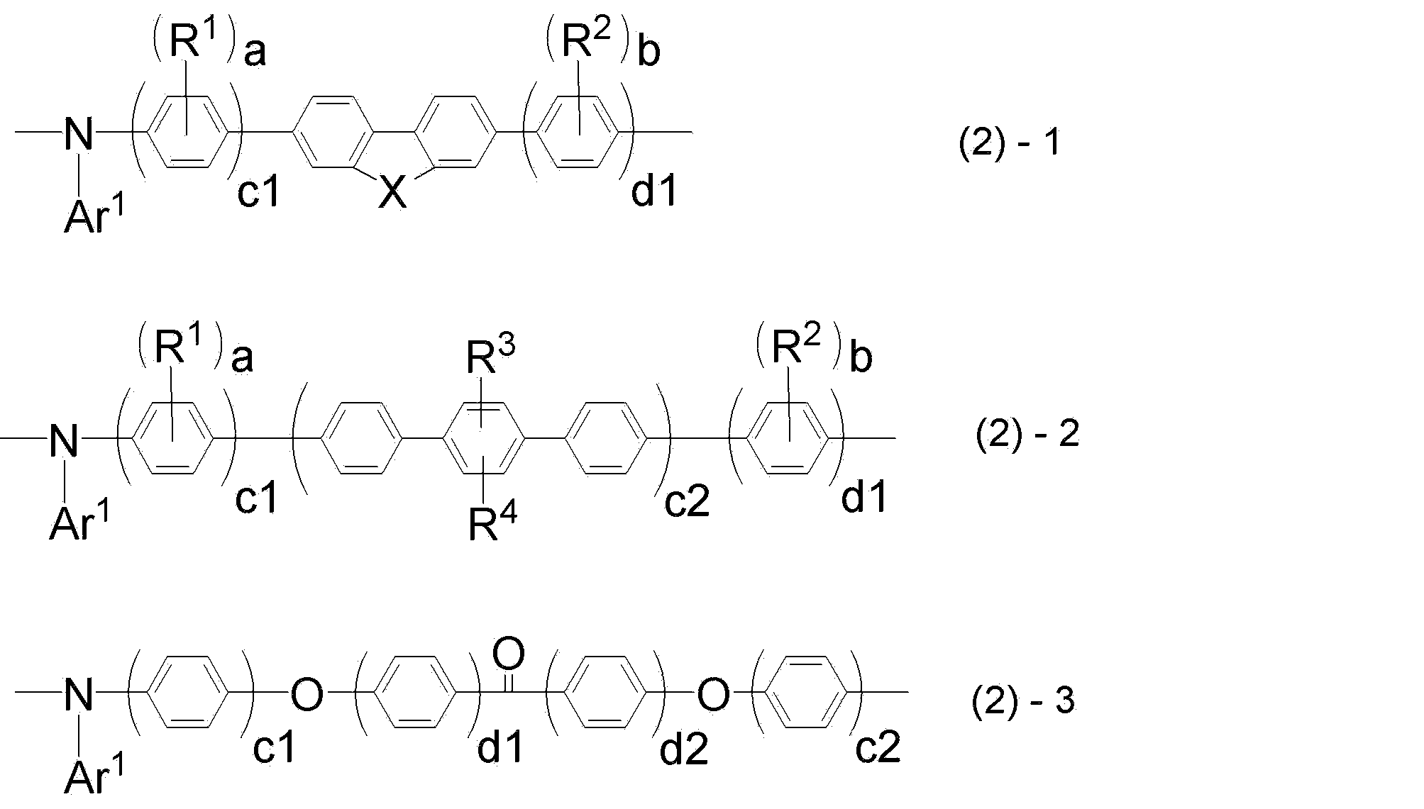
(式(2)-1~式(2)-3中、
Ar1は前記式(1)のAr1と同じであり、
Xは、-C(R5)(R6)-、-N(R7)-または-C(R11)(R12)-C(R13)(R14)-を表し、
R1~R4は、各々独立に、置換基を有していてもよいアルキル基、置換基を有していてもよいアルコキシ基、又は置換基を有していてもよいアラルキル基を表し、
R5~R7及びR11~R14は、各々独立に、置換基を有していてもよいアルキル基、置換基を有していてもよいアルコキシ基、置換基を有していてもよいアラルキル基、または置換基を有していてもよい芳香族炭化水素基を表し、
a、bは、各々独立に、0~4の整数であり、
c1、c2は、各々独立に、1~3の整数であり、
d1、d2は、各々独立に、0~4の整数であり、
R1、R2、R3、R4が該繰り返し単位中に複数ある場合は、R1、R2、R3、R4は同一であっても異なっていてもよい。) - さらに、下記(3)-1~(3)-3のいずれかで表わされる繰り返し単位を含む、請求項1~4のいずれか1項に記載の重合体。
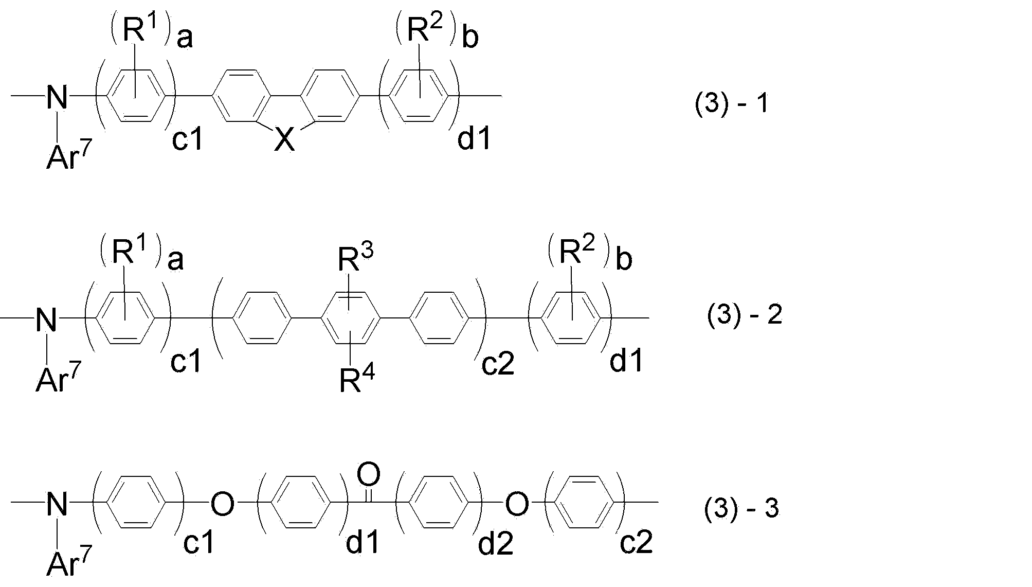
(式(3)-1~(3)-3中、
Ar7は、それぞれの繰り返し単位において独立に、置換基を有していてもよい芳香族炭化水素基、置換基を有していてもよい芳香族複素環基、又は置換基を有していてもよい芳香族炭化水素基若しくは置換基を有していてもよい芳香族複素環基が直接若しくは連結基を介して複数個連結した二価の基を表し、
X、R1、R2、R3、R4、a、b、c1、c2、d1、d2は、それぞれ前記式(2)-1~(2)-3と同じである。) - 前記重合体が、置換基として架橋性基を有する、請求項1~5のいずれか1項に記載の重合体。
- 前記重合体の重量平均分子量(Mw)が10,000以上であり、且つ、分散度(Mw/Mn)が3.5以下である、請求項1~6のいずれか1項に記載の重合体。
- 請求項1~7のいずれか1項に記載の重合体を含有する、有機電界発光素子用組成物。
- 基板上に、陽極、陰極、及び該陽極と該陰極との間に有機層を有する有機電界発光素子の製造方法であって、
請求項8に記載の有機電界発光素子用組成物を用いて、湿式成膜法により、該有機層を構成する層のうち少なくとも1層を形成する成膜ステップを含む、有機電界発光素子の製造方法。 - 前記有機層が正孔注入層及び正孔輸送層を有し、該正孔注入層及び正孔輸送層のうちの少なくとも一つの層が、前記成膜ステップで形成される層である、請求項9に記載の有機電界発光素子の製造方法。
- 前記有機層がさらに、発光層を有し、
前記正孔注入層、正孔輸送層及び発光層が、前記成膜ステップで形成される層である、請求項9又は10に記載の有機電界発光素子の製造方法。 - 基板上に、陽極、陰極、及び該陽極と該陰極との間に有機層を有し、該有機層が請求項1~7のいずれか1項に記載の重合体又は該重合体が架橋した重合体を含有する層を有する、有機電界発光素子。
- 前記重合体又は該重合体が架橋した重合体を含有する層が正孔輸送層であり、前記有機層がさらに発光層を有し、該発光層が該正孔輸送層に接しており、該発光層に含まれる材料の少なくとも一つが下記式(CzP)で表わされる部分構造を有する化合物を含む、請求項12に記載の有機電界発光素子。

- 前記式(CzP)で表わされる部分構造を有する化合物を含む前記発光層に含まれる材料は、正孔輸送性または電子輸送性の少なくともいずれかを有するホスト材料、または、発光材料である、請求項13に記載の有機電界発光素子。
- 前記ホスト材料の骨格は、芳香族構造、芳香族アミン構造、トリアリールアミン構造、ジベンゾフラン構造、ナフタレン構造、フェナントレン構造、フタロシアニン構造、ポルフィリン構造、チオフェン構造、ベンジルフェニル構造、フルオレン構造、キナクリドン構造、トリフェニレン構造、カルバゾール構造、ピレン構造、アントラセン構造、フェナントロリン構造、キノリン構造、ピリジン構造、ピリミジン構造、トリアジン構造、オキサジアゾール構造又はイミダゾール構造、カルバゾール構造、ジベンゾフラン構造、トリアリールアミン構造、ナフタレン構造、フェナントレン構造、ピレン構造のいずれかを有するものである請求項14に記載の有機電界発光素子。
- 前記発光層に含まれる、前記式(CzP)で表される部分構造を有する化合物が、下記式(14)~(16)のいずれかで表される低分子化合物であり、かつ、該低分子化合物の分子量が5,000以下である、請求項13~15のいずれか1項に記載の有機電界発光素子。
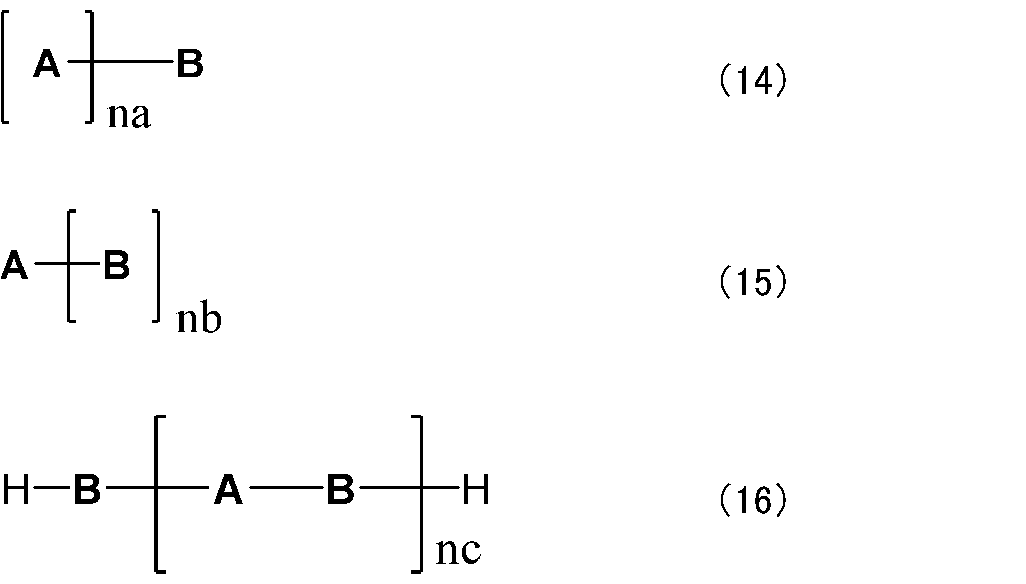
(式(14)~(16)中、
Aは前記式(CzP)で表される部分構造であり、置換基を有していてもよい。
Bは単結合または任意の部分構造を表す。
Aが複数存在する場合、同一であっても互いに異なっていてもよい。
Bが複数存在する場合、同一であっても互いに異なっていてもよい。
na、nb及びncは、それぞれ独立に、1以上、5以下の整数を表す。) - 前記式(14)で表される低分子化合物が、下記式(17)で表される低分子化合物である、請求項16に記載の有機電界発光素子。
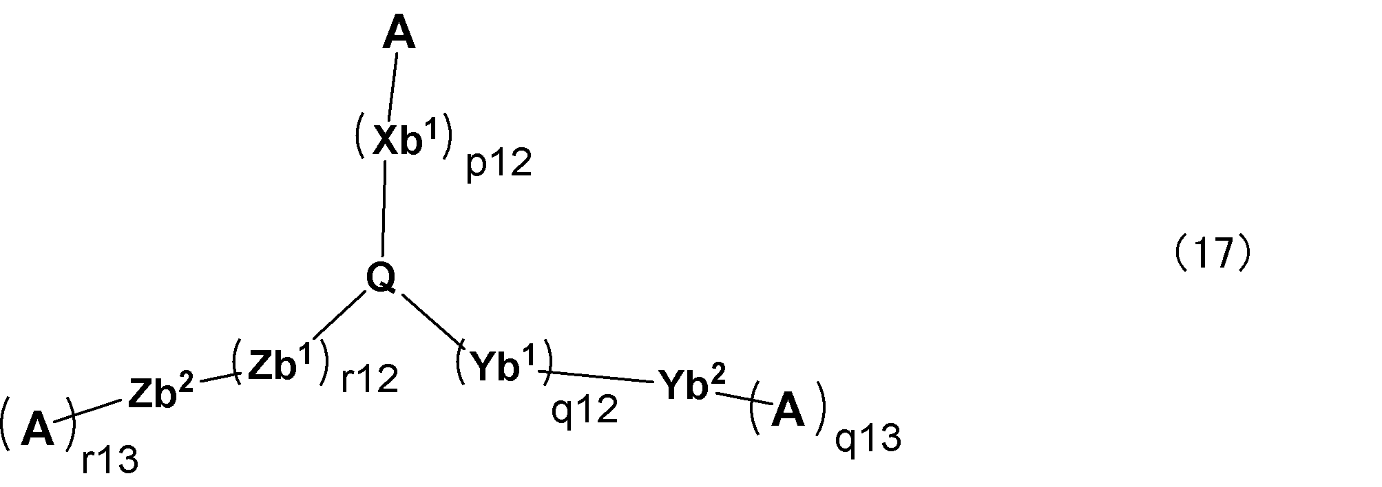
(上記式(17)において、
Qは、窒素原子または、下記構造式(18-1)~(18-3)のいずれかで表される3価の置換基のいずれかを表し、
Xb1、Yb1、及びZb1は、各々独立に、置換基を有していてもよい炭素数6~30の二価の炭化水素芳香環基、又は置換基を有していてもよい炭素数3~30の二価の複素芳香環基を表し、Xb1、Yb1、及びZb1のそれぞれはが複数存在する場合は同一であっても異なっていてもよく、
Aは、前記式(CzP)で表される部分構造であり、置換基を有していてもよく、かつ、複数存在するAは互いに同一であっても異なっていてもよく、
p12、q12、及びr12は、各々独立に、0以上6以下の整数を表し、
q13、r13は、各々独立に、0または1を表し、
q13が0の場合のYb2及び、r13が0の場合のZb2は各々独立に、水素原子、置換基を有していてもよい炭素数6~30の一価の炭化水素芳香環基、又は置換基を有していてもよい炭素数3~30の一価の複素芳香環基を表し、
q13が1の場合のYb2は直接結合であり、
r13が1の場合のZb2は直接結合であり
式(18-1)~(18-3)において、一つの構造式中の3つの*は、それぞれXb1、Yb1、又はZb1のいずれか基との結合位置を表す。)
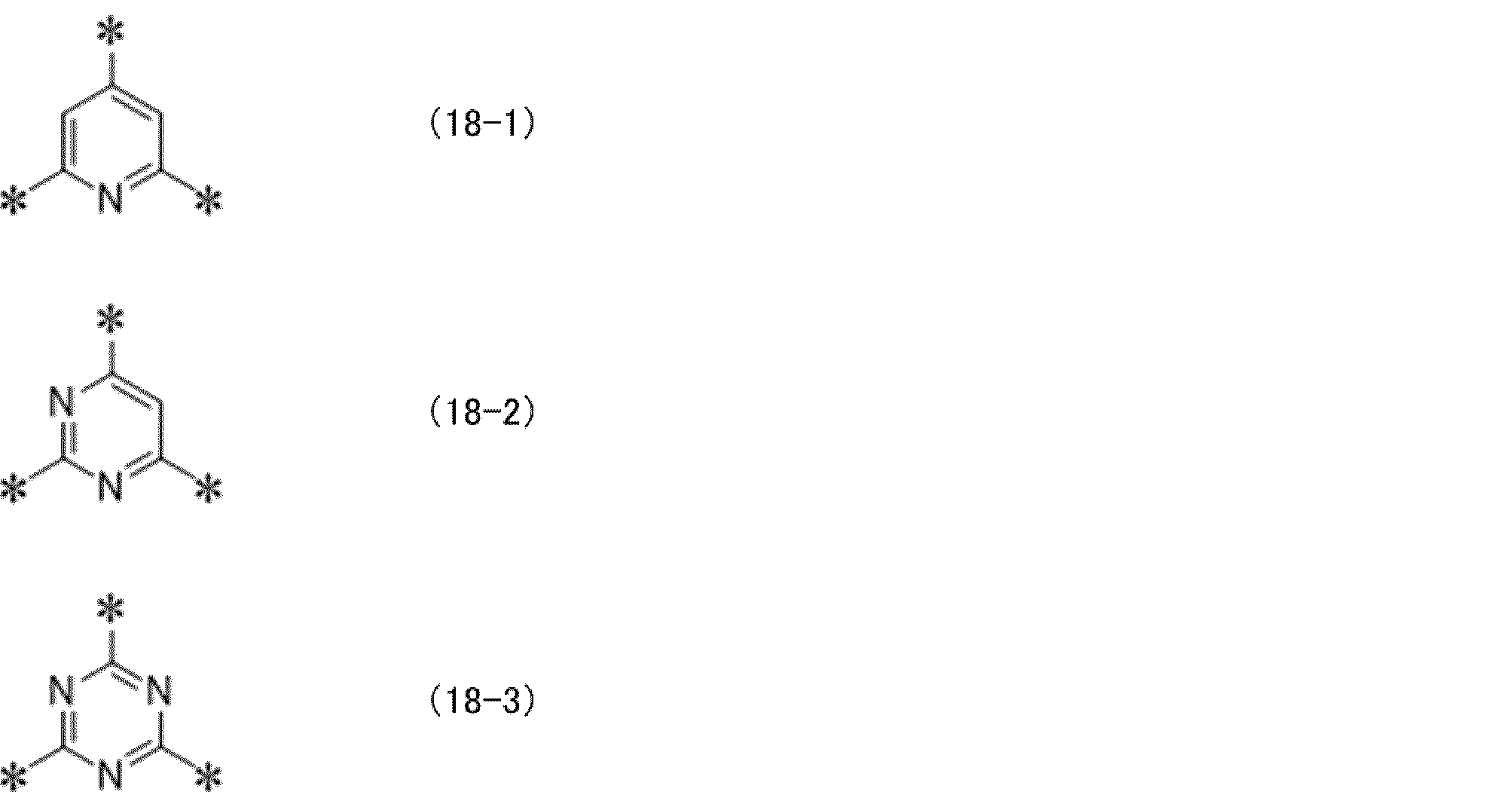
- 前記式(16)で表される低分子化合物が、下記式(19)で表される低分子化合物である、請求項16に記載の有機電界発光素子。

(上記式(19)中、
Xc1及びYc1は、各々独立に、置換基を有していてもよい炭素数6~30の二価の炭化水素芳香環基、又は置換基を有していてもよい炭素数3~30の二価の複素芳香環基を表し、
Xc2及びYc2は、各々独立に、水素原子、置換基を有していてもよい一価の炭素数6~30の炭化水素芳香環基、又は置換基を有していてもよい炭素数3~30の一価の複素芳香環基を表し、
Xc1及びYc1のそれぞれは複数存在する場合は同一であっても異なっていてもよく、
Aは前記式(CzP)で表される部分構造であり、置換基を有していてもよく、
s11及びt11は、各々独立に、0以上6以下の整数を表し、
ncは、1以上、5以下の整数を表す。) - 前記式(17)で表される低分子化合物が、下記式(17-1)~(17-6)のいずれかで表される化合物である、請求項17に記載の有機電界発光素子。
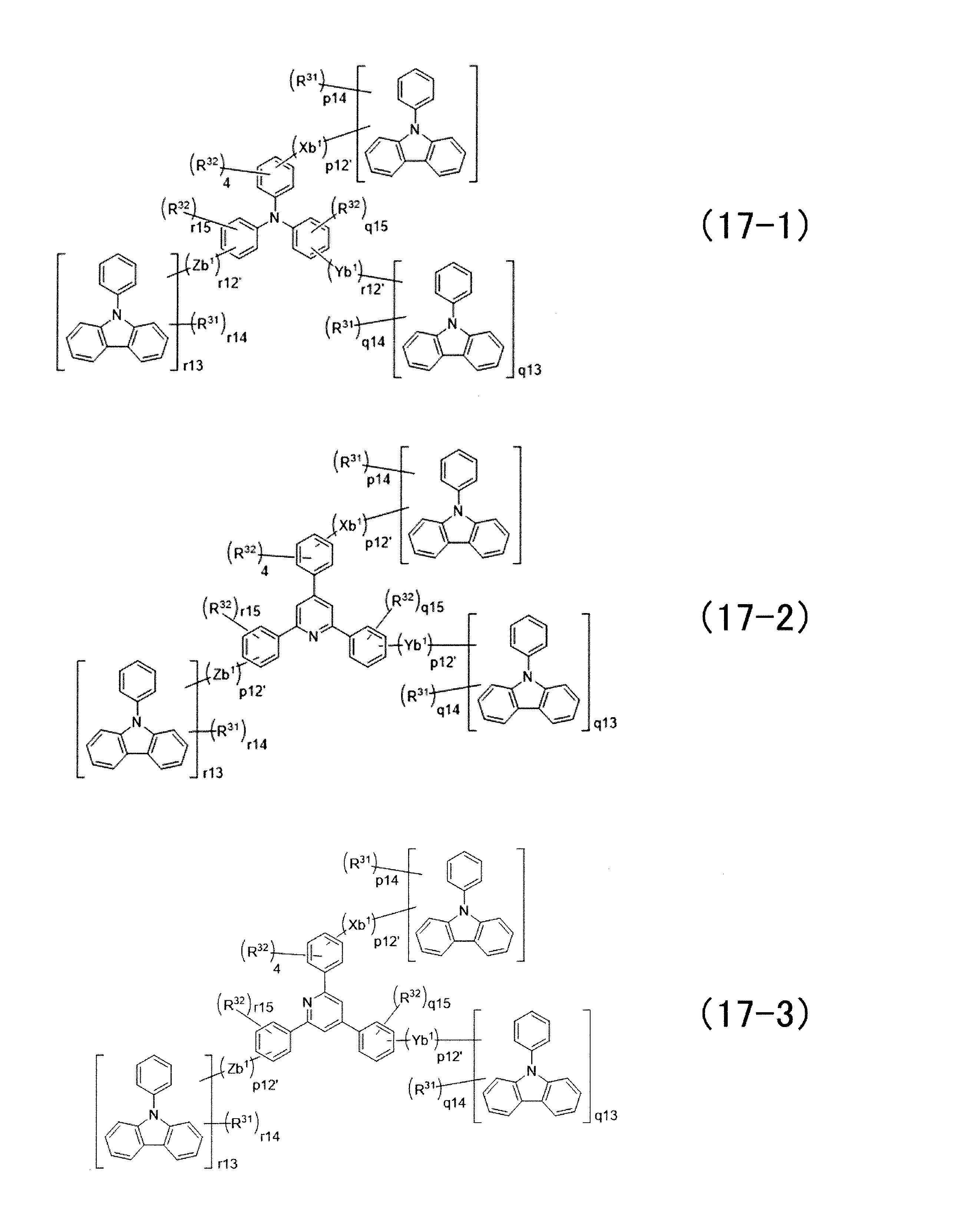
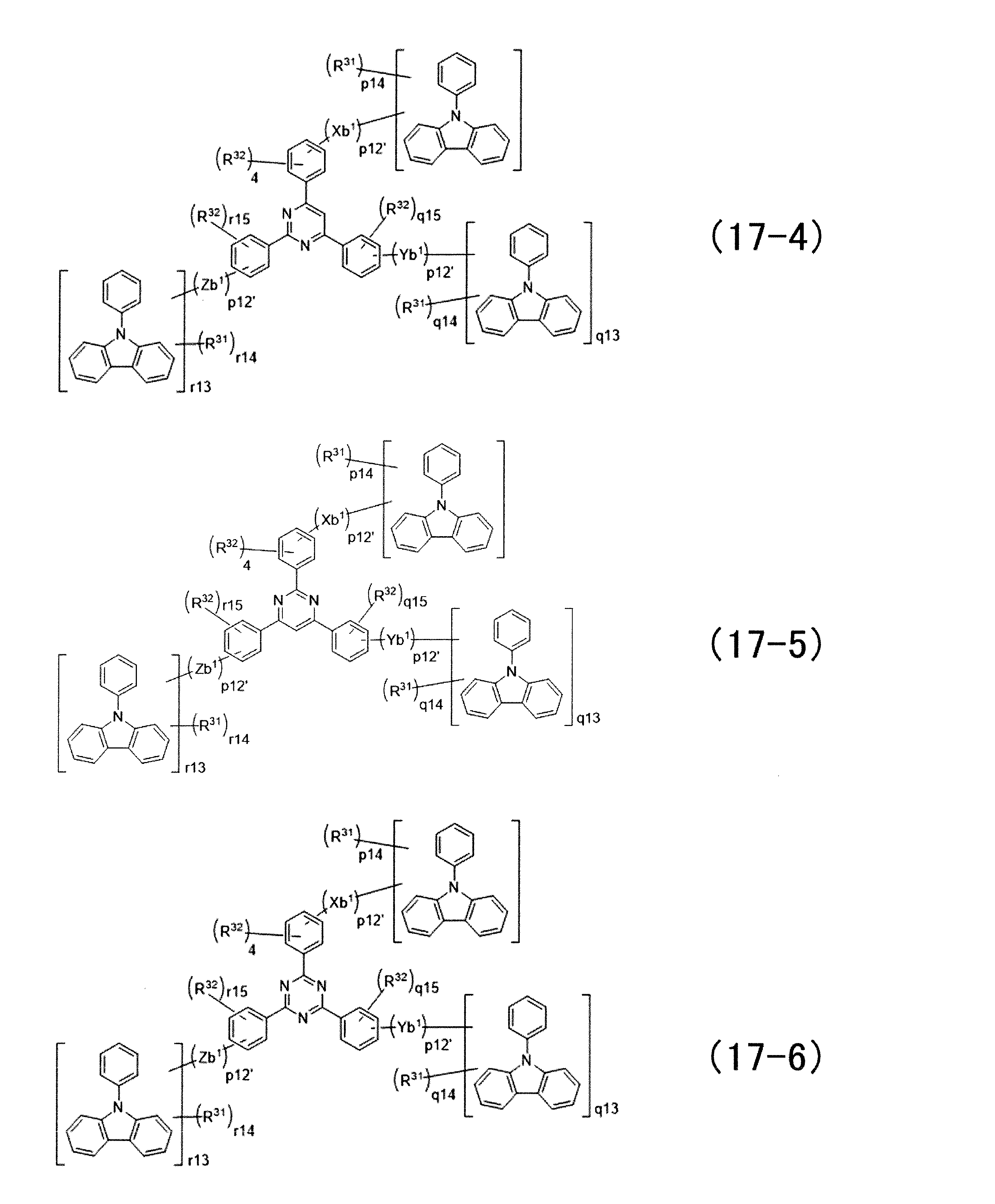
(上記一般式(17-1)~(17-6)中、
p12’は、1以上5以下の整数を表し、
q12’及びr12’は、各々独立に、0以上5以下の整数を表し、
p14は12であり、
q14はq13が1の場合は12であり、q13が0の場合は存在せず、
r14はr13が1の場合は12であり、r13が0の場合は存在せず、
q15及びr15は、各々独立に、4又は5であり、
R31及びR32は、各々独立に、水素原子または置換基であり、
Xb1、Yb1、Zb1、q13、r13は、それぞれ前記式(17)と同じである。) - 前記式(19)で表される低分子化合物が、下記式(19-1)で表される化合物である、請求項18に記載の有機電界発光素子。
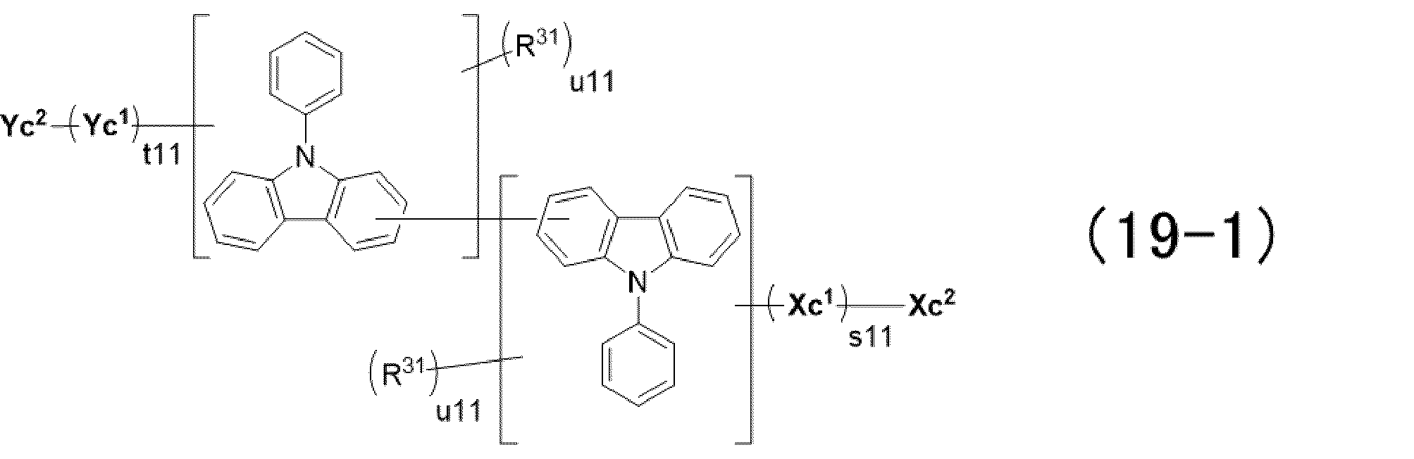
(上記一般式(19-1)において、
R31は、水素原子または置換基であり、
u11は、11を表し、
Xc1、Yc1、Xc1、Yc1、t11、及びs11は、それぞれ前記式(19)と同じである。) - 請求項12~20のいずれか1項に記載の有機電界発光素子を備える、有機EL表示装置。
- 請求項12~20のいずれか1項に記載の有機電界発光素子を備える、有機EL照明。
Priority Applications (3)
| Application Number | Priority Date | Filing Date | Title |
|---|---|---|---|
| JP2021502161A JP7501517B2 (ja) | 2019-02-20 | 2020-02-20 | 重合体、有機電界発光素子、有機el表示装置及び有機el照明 |
| CN202080015786.8A CN113454141B (zh) | 2019-02-20 | 2020-02-20 | 聚合物、有机电致发光元件、有机el显示装置和有机el照明 |
| KR1020217028596A KR102888035B1 (ko) | 2019-02-20 | 2020-02-20 | 중합체, 유기 전계 발광 소자, 유기 el 표시 장치 및 유기 el 조명 |
Applications Claiming Priority (6)
| Application Number | Priority Date | Filing Date | Title |
|---|---|---|---|
| JP2019027989 | 2019-02-20 | ||
| JP2019-049585 | 2019-03-18 | ||
| JP2019049585 | 2019-03-18 | ||
| JP2019-158088 | 2019-08-30 | ||
| JP2019158088 | 2019-08-30 | ||
| JP2019-027989 | 2019-12-17 |
Publications (1)
| Publication Number | Publication Date |
|---|---|
| WO2020171190A1 true WO2020171190A1 (ja) | 2020-08-27 |
Family
ID=72143625
Family Applications (1)
| Application Number | Title | Priority Date | Filing Date |
|---|---|---|---|
| PCT/JP2020/006946 Ceased WO2020171190A1 (ja) | 2019-02-20 | 2020-02-20 | 重合体、有機電界発光素子、有機el表示装置及び有機el照明 |
Country Status (5)
| Country | Link |
|---|---|
| JP (1) | JP7501517B2 (ja) |
| KR (1) | KR102888035B1 (ja) |
| CN (1) | CN113454141B (ja) |
| TW (2) | TWI832973B (ja) |
| WO (1) | WO2020171190A1 (ja) |
Cited By (6)
| Publication number | Priority date | Publication date | Assignee | Title |
|---|---|---|---|---|
| JPWO2021166900A1 (ja) * | 2020-02-20 | 2021-08-26 | ||
| JPWO2022059725A1 (ja) * | 2020-09-18 | 2022-03-24 | ||
| JP2022098834A (ja) * | 2020-12-22 | 2022-07-04 | 三星電子株式会社 | 共重合体、ならびに当該共重合体を用いるエレクトロルミネッセンス素子材料およびエレクトロルミネッセンス素子 |
| WO2022230821A1 (ja) * | 2021-04-28 | 2022-11-03 | 三菱ケミカル株式会社 | 有機半導体素子の製造方法 |
| JP2023051507A (ja) * | 2021-09-30 | 2023-04-11 | 三菱ケミカル株式会社 | 有機電界発光素子用組成物、及び有機電界発光素子の製造方法 |
| WO2025099795A1 (ja) * | 2023-11-06 | 2025-05-15 | シャープディスプレイテクノロジー株式会社 | 発光素子、発光素子の製造方法、表示装置及び表示装置の製造方法 |
Citations (5)
| Publication number | Priority date | Publication date | Assignee | Title |
|---|---|---|---|---|
| WO2009110360A1 (ja) * | 2008-03-05 | 2009-09-11 | 出光興産株式会社 | 高分子化合物及びそれを用いた有機エレクトロルミネッセンス素子 |
| JP2010196040A (ja) * | 2009-01-29 | 2010-09-09 | Sumitomo Chemical Co Ltd | 高分子化合物及びそれを用いる発光素子 |
| WO2011099531A1 (ja) * | 2010-02-10 | 2011-08-18 | 三菱化学株式会社 | 重合体、有機電界発光素子材料、有機電界発光素子用組成物、有機電界発光素子、表示装置及び照明装置 |
| JP2012104536A (ja) * | 2010-11-08 | 2012-05-31 | Konica Minolta Holdings Inc | 有機エレクトロルミネッセンス素子、照明装置及び表示装置 |
| WO2016031639A1 (ja) * | 2014-08-28 | 2016-03-03 | 住友化学株式会社 | 高分子化合物およびそれを用いた発光素子 |
Family Cites Families (9)
| Publication number | Priority date | Publication date | Assignee | Title |
|---|---|---|---|---|
| GB0329364D0 (en) | 2003-12-19 | 2004-01-21 | Cambridge Display Tech Ltd | Optical device |
| TW200906909A (en) | 2007-04-04 | 2009-02-16 | Mitsui Chemicals Inc | Polymers containing sulfo group and intermediate thereof, and organic electroluminescent element containing the polymer |
| US8692234B2 (en) | 2008-04-02 | 2014-04-08 | Mitsubishi Chemical Corporation | Polymer compound, net-like polymer compound produced by crosslinking the polymer compound, composition for organic electroluminescence element, organic electroluminescence element, organic EL display, and organic EL lighting |
| JP2010034496A (ja) | 2008-06-25 | 2010-02-12 | Hitachi Chem Co Ltd | 有機エレクトロルミネセンス素子、並びにこれを備えた表示素子、照明装置、及び表示装置 |
| TW201204687A (en) | 2010-06-17 | 2012-02-01 | Du Pont | Electroactive materials |
| JP5874242B2 (ja) | 2011-08-26 | 2016-03-02 | 東洋インキScホールディングス株式会社 | 有機エレクトロルミネッセンス素子用材料およびその用途 |
| JP6090317B2 (ja) | 2012-06-19 | 2017-03-08 | 住友化学株式会社 | 高分子化合物およびそれを用いた発光素子 |
| JP6442977B2 (ja) | 2014-10-22 | 2018-12-26 | 三菱ケミカル株式会社 | 重合体、有機電界発光素子用組成物、有機電界発光素子、有機el表示装置及び有機el照明 |
| JP6866576B2 (ja) * | 2015-06-05 | 2021-04-28 | 三菱ケミカル株式会社 | 重合体、有機電界発光素子用組成物、有機電界発光素子、有機el表示装置及び有機el照明 |
-
2020
- 2020-02-20 KR KR1020217028596A patent/KR102888035B1/ko active Active
- 2020-02-20 CN CN202080015786.8A patent/CN113454141B/zh active Active
- 2020-02-20 JP JP2021502161A patent/JP7501517B2/ja active Active
- 2020-02-20 TW TW109105562A patent/TWI832973B/zh active
- 2020-02-20 TW TW113101792A patent/TW202426541A/zh unknown
- 2020-02-20 WO PCT/JP2020/006946 patent/WO2020171190A1/ja not_active Ceased
Patent Citations (5)
| Publication number | Priority date | Publication date | Assignee | Title |
|---|---|---|---|---|
| WO2009110360A1 (ja) * | 2008-03-05 | 2009-09-11 | 出光興産株式会社 | 高分子化合物及びそれを用いた有機エレクトロルミネッセンス素子 |
| JP2010196040A (ja) * | 2009-01-29 | 2010-09-09 | Sumitomo Chemical Co Ltd | 高分子化合物及びそれを用いる発光素子 |
| WO2011099531A1 (ja) * | 2010-02-10 | 2011-08-18 | 三菱化学株式会社 | 重合体、有機電界発光素子材料、有機電界発光素子用組成物、有機電界発光素子、表示装置及び照明装置 |
| JP2012104536A (ja) * | 2010-11-08 | 2012-05-31 | Konica Minolta Holdings Inc | 有機エレクトロルミネッセンス素子、照明装置及び表示装置 |
| WO2016031639A1 (ja) * | 2014-08-28 | 2016-03-03 | 住友化学株式会社 | 高分子化合物およびそれを用いた発光素子 |
Cited By (16)
| Publication number | Priority date | Publication date | Assignee | Title |
|---|---|---|---|---|
| WO2021166900A1 (ja) * | 2020-02-20 | 2021-08-26 | 三菱ケミカル株式会社 | 有機電界発光素子、有機el表示装置及び有機el照明 |
| JPWO2021166900A1 (ja) * | 2020-02-20 | 2021-08-26 | ||
| JP7647737B2 (ja) | 2020-02-20 | 2025-03-18 | 三菱ケミカル株式会社 | 有機電界発光素子、有機el表示装置及び有機el照明 |
| CN116194981A (zh) * | 2020-09-18 | 2023-05-30 | 三菱化学株式会社 | 聚合物 |
| JPWO2022059725A1 (ja) * | 2020-09-18 | 2022-03-24 | ||
| WO2022059725A1 (ja) * | 2020-09-18 | 2022-03-24 | 三菱ケミカル株式会社 | 重合体 |
| JP7882110B2 (ja) | 2020-09-18 | 2026-06-30 | 三菱ケミカル株式会社 | 重合体 |
| JP2022098834A (ja) * | 2020-12-22 | 2022-07-04 | 三星電子株式会社 | 共重合体、ならびに当該共重合体を用いるエレクトロルミネッセンス素子材料およびエレクトロルミネッセンス素子 |
| JP7651296B2 (ja) | 2020-12-22 | 2025-03-26 | 三星電子株式会社 | 共重合体、ならびに当該共重合体を用いるエレクトロルミネッセンス素子材料およびエレクトロルミネッセンス素子 |
| CN117296451A (zh) * | 2021-04-28 | 2023-12-26 | 三菱化学株式会社 | 有机半导体元件的制造方法 |
| JPWO2022230821A1 (ja) * | 2021-04-28 | 2022-11-03 | ||
| JP7878301B2 (ja) | 2021-04-28 | 2026-06-23 | 三菱ケミカル株式会社 | 有機半導体素子の製造方法 |
| WO2022230821A1 (ja) * | 2021-04-28 | 2022-11-03 | 三菱ケミカル株式会社 | 有機半導体素子の製造方法 |
| JP2023051507A (ja) * | 2021-09-30 | 2023-04-11 | 三菱ケミカル株式会社 | 有機電界発光素子用組成物、及び有機電界発光素子の製造方法 |
| JP7864986B2 (ja) | 2021-09-30 | 2026-05-26 | 三菱ケミカル株式会社 | 有機電界発光素子用組成物、及び有機電界発光素子の製造方法 |
| WO2025099795A1 (ja) * | 2023-11-06 | 2025-05-15 | シャープディスプレイテクノロジー株式会社 | 発光素子、発光素子の製造方法、表示装置及び表示装置の製造方法 |
Also Published As
| Publication number | Publication date |
|---|---|
| TW202426541A (zh) | 2024-07-01 |
| TWI832973B (zh) | 2024-02-21 |
| CN113454141B (zh) | 2024-03-26 |
| KR20210127956A (ko) | 2021-10-25 |
| CN113454141A (zh) | 2021-09-28 |
| KR102888035B1 (ko) | 2025-11-18 |
| JP7501517B2 (ja) | 2024-06-18 |
| TW202041569A (zh) | 2020-11-16 |
| JPWO2020171190A1 (ja) | 2021-12-23 |
Similar Documents
| Publication | Publication Date | Title |
|---|---|---|
| JP5793878B2 (ja) | 重合体、有機電界発光素子材料、有機電界発光素子用組成物、有機電界発光素子、表示装置及び照明装置 | |
| JP7513069B2 (ja) | 重合体、有機電界発光素子用組成物、有機電界発光素子、有機el表示装置、有機el照明及び有機電界発光素子の製造方法 | |
| KR102229736B1 (ko) | 모노아민 화합물, 전하 수송 재료, 전하 수송막용 조성물, 유기 전계 발광 소자, 유기 el 표시 장치 및 유기 el 조명 | |
| JP7501517B2 (ja) | 重合体、有機電界発光素子、有機el表示装置及び有機el照明 | |
| JP2019218550A (ja) | 重合体、有機電界発光素子用組成物、有機電界発光素子、有機el表示装置及び有機el照明 | |
| JP7574805B2 (ja) | 重合体、有機電界発光素子用組成物、正孔輸送層又は正孔注入層形成用組成物、有機電界発光素子、有機el表示装置及び有機el照明 | |
| JP7647737B2 (ja) | 有機電界発光素子、有機el表示装置及び有機el照明 | |
| WO2022059725A1 (ja) | 重合体 | |
| JPWO2021166900A5 (ja) | ||
| JP2021127325A (ja) | 芳香族ジアミン誘導体 |
Legal Events
| Date | Code | Title | Description |
|---|---|---|---|
| 121 | Ep: the epo has been informed by wipo that ep was designated in this application |
Ref document number: 20758830 Country of ref document: EP Kind code of ref document: A1 |
|
| ENP | Entry into the national phase |
Ref document number: 2021502161 Country of ref document: JP Kind code of ref document: A |
|
| NENP | Non-entry into the national phase |
Ref country code: DE |
|
| ENP | Entry into the national phase |
Ref document number: 20217028596 Country of ref document: KR Kind code of ref document: A |
|
| 122 | Ep: pct application non-entry in european phase |
Ref document number: 20758830 Country of ref document: EP Kind code of ref document: A1 |