WO2020171176A1 - 吸収体及びそれを備える吸収性物品 - Google Patents
吸収体及びそれを備える吸収性物品 Download PDFInfo
- Publication number
- WO2020171176A1 WO2020171176A1 PCT/JP2020/006868 JP2020006868W WO2020171176A1 WO 2020171176 A1 WO2020171176 A1 WO 2020171176A1 JP 2020006868 W JP2020006868 W JP 2020006868W WO 2020171176 A1 WO2020171176 A1 WO 2020171176A1
- Authority
- WO
- WIPO (PCT)
- Prior art keywords
- sap
- base material
- liquid
- absorber
- sheet
- Prior art date
- Legal status (The legal status is an assumption and is not a legal conclusion. Google has not performed a legal analysis and makes no representation as to the accuracy of the status listed.)
- Ceased
Links
Images

















Classifications
-
- A—HUMAN NECESSITIES
- A61—MEDICAL OR VETERINARY SCIENCE; HYGIENE
- A61F—FILTERS IMPLANTABLE INTO BLOOD VESSELS; PROSTHESES; DEVICES PROVIDING PATENCY TO, OR PREVENTING COLLAPSING OF, TUBULAR STRUCTURES OF THE BODY, e.g. STENTS; ORTHOPAEDIC, NURSING OR CONTRACEPTIVE DEVICES; FOMENTATION; TREATMENT OR PROTECTION OF EYES OR EARS; BANDAGES, DRESSINGS OR ABSORBENT PADS; FIRST-AID KITS
- A61F13/00—Bandages or dressings; Absorbent pads
- A61F13/15—Absorbent pads, e.g. sanitary towels, swabs or tampons for external or internal application to the body; Supporting or fastening means therefor; Tampon applicators
- A61F13/53—Absorbent pads, e.g. sanitary towels, swabs or tampons for external or internal application to the body; Supporting or fastening means therefor; Tampon applicators characterised by the absorbing medium
-
- A—HUMAN NECESSITIES
- A61—MEDICAL OR VETERINARY SCIENCE; HYGIENE
- A61F—FILTERS IMPLANTABLE INTO BLOOD VESSELS; PROSTHESES; DEVICES PROVIDING PATENCY TO, OR PREVENTING COLLAPSING OF, TUBULAR STRUCTURES OF THE BODY, e.g. STENTS; ORTHOPAEDIC, NURSING OR CONTRACEPTIVE DEVICES; FOMENTATION; TREATMENT OR PROTECTION OF EYES OR EARS; BANDAGES, DRESSINGS OR ABSORBENT PADS; FIRST-AID KITS
- A61F13/00—Bandages or dressings; Absorbent pads
- A61F13/15—Absorbent pads, e.g. sanitary towels, swabs or tampons for external or internal application to the body; Supporting or fastening means therefor; Tampon applicators
- A61F13/53—Absorbent pads, e.g. sanitary towels, swabs or tampons for external or internal application to the body; Supporting or fastening means therefor; Tampon applicators characterised by the absorbing medium
- A61F13/534—Absorbent pads, e.g. sanitary towels, swabs or tampons for external or internal application to the body; Supporting or fastening means therefor; Tampon applicators characterised by the absorbing medium having an inhomogeneous composition through the thickness of the pad
-
- A—HUMAN NECESSITIES
- A61—MEDICAL OR VETERINARY SCIENCE; HYGIENE
- A61F—FILTERS IMPLANTABLE INTO BLOOD VESSELS; PROSTHESES; DEVICES PROVIDING PATENCY TO, OR PREVENTING COLLAPSING OF, TUBULAR STRUCTURES OF THE BODY, e.g. STENTS; ORTHOPAEDIC, NURSING OR CONTRACEPTIVE DEVICES; FOMENTATION; TREATMENT OR PROTECTION OF EYES OR EARS; BANDAGES, DRESSINGS OR ABSORBENT PADS; FIRST-AID KITS
- A61F13/00—Bandages or dressings; Absorbent pads
- A61F13/15—Absorbent pads, e.g. sanitary towels, swabs or tampons for external or internal application to the body; Supporting or fastening means therefor; Tampon applicators
- A61F13/53—Absorbent pads, e.g. sanitary towels, swabs or tampons for external or internal application to the body; Supporting or fastening means therefor; Tampon applicators characterised by the absorbing medium
- A61F13/534—Absorbent pads, e.g. sanitary towels, swabs or tampons for external or internal application to the body; Supporting or fastening means therefor; Tampon applicators characterised by the absorbing medium having an inhomogeneous composition through the thickness of the pad
- A61F13/535—Absorbent pads, e.g. sanitary towels, swabs or tampons for external or internal application to the body; Supporting or fastening means therefor; Tampon applicators characterised by the absorbing medium having an inhomogeneous composition through the thickness of the pad inhomogeneous in the plane of the pad, e.g. core absorbent layers being of different sizes
-
- A—HUMAN NECESSITIES
- A61—MEDICAL OR VETERINARY SCIENCE; HYGIENE
- A61F—FILTERS IMPLANTABLE INTO BLOOD VESSELS; PROSTHESES; DEVICES PROVIDING PATENCY TO, OR PREVENTING COLLAPSING OF, TUBULAR STRUCTURES OF THE BODY, e.g. STENTS; ORTHOPAEDIC, NURSING OR CONTRACEPTIVE DEVICES; FOMENTATION; TREATMENT OR PROTECTION OF EYES OR EARS; BANDAGES, DRESSINGS OR ABSORBENT PADS; FIRST-AID KITS
- A61F13/00—Bandages or dressings; Absorbent pads
- A61F13/15—Absorbent pads, e.g. sanitary towels, swabs or tampons for external or internal application to the body; Supporting or fastening means therefor; Tampon applicators
- A61F13/53—Absorbent pads, e.g. sanitary towels, swabs or tampons for external or internal application to the body; Supporting or fastening means therefor; Tampon applicators characterised by the absorbing medium
- A61F13/534—Absorbent pads, e.g. sanitary towels, swabs or tampons for external or internal application to the body; Supporting or fastening means therefor; Tampon applicators characterised by the absorbing medium having an inhomogeneous composition through the thickness of the pad
- A61F13/537—Absorbent pads, e.g. sanitary towels, swabs or tampons for external or internal application to the body; Supporting or fastening means therefor; Tampon applicators characterised by the absorbing medium having an inhomogeneous composition through the thickness of the pad characterised by a layer facilitating or inhibiting flow in one direction or plane, e.g. a wicking layer
Definitions
- the present invention relates to an absorber including SAP that is a superabsorbent polymer.
- Absorbent articles such as disposable diapers, urine pads, and sanitary products are equipped with absorbent bodies that absorb liquids such as urine and body fluids.
- Pulp or super absorbent polymer (Super Absorbent Polymer: SAP) is used as the absorber.
- SAP Super Absorbent Polymer
- the absorber is formed into a thin sheet shape, a mat shape, or the like.
- Patent Document 1 discloses an absorbent composite in which SAP particles are fixed to a non-woven fabric substrate or the like using a binder such as a thermoplastic resin.
- the absorber in which SAP particles are fixed to the nonwoven fabric substrate absorbs and holds the liquid by SAP.
- the liquid that has moved to the end of the nonwoven fabric through the surface or inside of the nonwoven fabric base material may leak from the absorber without being absorbed by SAP.
- an object of the present invention is to provide a technique capable of suppressing liquid leakage.
- an SAP layer containing particles of SAP which is a superabsorbent polymer, is provided on the front surface and the back surface of a substrate formed of a nonwoven fabric.
- the present invention relates to an absorbent body, which comprises a base material formed of a non-woven fabric, and a superabsorbent polymer which is disposed on both sides in the width direction of the surface of the base material along the longitudinal direction of the base material. And a second SAP layer that is disposed on the back surface of the base material and that includes SAP particles.
- a groove extending in the longitudinal direction of the base material may be formed on the front surface side of the base material and in the widthwise central portion of the base material.
- the absorber may include a first nonwoven fabric sheet arranged to cover the front surface of the base material and a second nonwoven fabric sheet arranged to cover the back surface of the base material.
- the absorbent body includes a core wrap sheet that covers the outer periphery of an absorbent composite including the base material, the first SAP layer, the second SAP layer, the first nonwoven fabric sheet, and the second nonwoven fabric sheet. May be.
- the present invention is an absorbent article that absorbs urine discharged by a wearer, a liquid-impermeable backsheet, a liquid-permeable topsheet joined to the backsheet, and the backsheet.
- the absorber according to any one of the above, which is arranged between the top sheet and the absorbent article.
- liquid leakage can be suppressed.
- FIG. 1 is a plan view of the absorber according to the first embodiment.
- FIG. 2 is a cross-sectional view of the absorber according to the first embodiment.
- FIG. 3 is a sectional view of the absorber according to the first embodiment.
- FIG. 4 is a plan view of the absorber according to the first embodiment.
- FIG. 5 is a sectional view of the absorber according to the first embodiment.
- FIG. 6 is a cross-sectional view of the absorber according to the first embodiment.
- FIG. 7 is a plan view of the absorber according to the second embodiment.
- FIG. 8 is a cross-sectional view of the absorber according to the second embodiment.
- FIG. 9 is a plan view of the absorber according to the second embodiment.
- FIG. 1 is a plan view of the absorber according to the first embodiment.
- FIG. 2 is a cross-sectional view of the absorber according to the first embodiment.
- FIG. 3 is a sectional view of the absorber according to the first embodiment.
- FIG. 10 is a cross-sectional view of the absorbent body according to the second embodiment.
- FIG. 11 is a cross-sectional view of the absorber according to the second embodiment.
- FIG. 12 is a plan view of the absorber according to the third embodiment.
- FIG. 13 is a cross-sectional view of the absorber according to the third embodiment.
- FIG. 14 is a plan view of the absorber according to the third embodiment.
- FIG. 15 is a sectional view of the absorber according to the third embodiment.
- FIG. 16 is a cross-sectional view of the absorber according to the third embodiment.
- FIG. 17 is a plan view of the absorber according to the third embodiment.
- FIG. 18 is a cross-sectional view of the absorber according to the third embodiment.
- FIG. 19 is a plan view of the absorber according to the fourth embodiment.
- 20 is a cross-sectional view of the absorbent body cut along the AA cross section shown in FIG. 19.
- 21 is a cross-sectional view of an absorber similar to FIG.
- FIG. 22 is a diagram showing a first example of a portion that is water repellent.
- FIG. 23 is a diagram showing a second example of a portion that has been subjected to water repellent finishing.
- FIG. 24 is a cross-sectional view of the absorber taken along the line BB shown in FIG.
- FIG. 25: is sectional drawing of the absorber similar to FIG.
- FIG. 26 is a plan view of the absorber according to the fifth embodiment.
- FIG. 27 is a sectional view of the absorber according to the fifth embodiment.
- FIG. 28 is a plan view of the absorber according to the fifth embodiment.
- FIG. 29 is a cross-sectional view of the absorber according to the fifth embodiment.
- FIG. 30 is a cross-sectional view of the absorber according to the fifth embodiment.
- FIG. 31 is a perspective view of a tape-type disposable diaper.
- FIG. 32 is an exploded perspective view of the diaper.
- FIG. 33 is a cross-sectional view when the crotch region is cut in the width direction.
- FIG. 34 is a cross-sectional view when the crotch region is cut in the width direction.
- the absorber according to the first embodiment of the present invention will be described.
- the absorber in which the SAP particles are fixed to the nonwoven fabric substrate absorbs and holds the liquid by SAP.
- SAP absorbs urine
- the absorbent body expands as a whole.
- the position facing the urethral meatus absorbs and swells urine in an early stage of the urination period as compared with other regions. If the position of the absorbent body facing the urethral meatus expands at an early stage of the urination period, then the excreted urine may flow in the width direction of the absorbent body. If a liquid such as urine flows in the width direction of the absorber, the liquid may leak.
- the present embodiment aims to provide a technique capable of suppressing liquid leakage.
- the liquid diffusion layer is formed on the surface of the liquid diffusion layer formed of a non-woven fabric, and on both sides in the width direction along the center portion in the width direction of the liquid diffusion layer.
- a SAP layer extending in the longitudinal direction.
- the present embodiment is an absorber, which is a liquid diffusion layer formed of a non-woven fabric, and an SAP layer containing particles of SAP that is a superabsorbent polymer. And a SAP layer that is arranged on both sides in the width direction along the center in the width direction of the liquid diffusion layer and that extends in the longitudinal direction of the liquid diffusion layer.
- a groove may be formed on the surface side of the liquid diffusion layer in the widthwise central portion and along the SAP layers on both sides.
- the absorbent body may include a first nonwoven fabric sheet arranged to cover the surface of the liquid diffusion layer and a second nonwoven fabric sheet arranged to cover the back surface of the liquid diffusion layer.
- the absorbent body may include a core wrap sheet that covers the outer periphery of an absorbent composite including the liquid diffusion layer, the SAP layer, the first nonwoven fabric sheet, and the second nonwoven fabric sheet.
- the absorbent article absorbs the liquid discharged by the wearer, the absorbent article absorbs the liquid discharged by the wearer, and the liquid impermeable backsheet is joined to the backsheet.
- a liquid-permeable topsheet and the absorber arranged between the backsheet and the topsheet may be provided.
- liquid leakage can be suppressed.
- FIG. 1 is a plan view of the absorber according to the first embodiment.
- the absorber 6A is formed in a sheet shape having a rectangular shape in a plan view.
- FIG. 1 shows a state in which the absorber 6A is viewed from the surface side, which is the skin facing surface side facing the wearer's skin when the absorber 6A is arranged in an absorbent article such as a diaper.
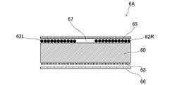
- FIG. 2 is a cross-sectional view of the absorbent body 6A taken along the line AA shown in FIG. 1 (a cross section along the width direction of the absorbent body 6A).
- the absorber 6A has a uniform cross section over the entire longitudinal direction. Note that, in FIG. 2, gaps are provided between the constituent elements in order to make the constituent elements of the absorber 6A easy to understand, but in reality, almost no gap is formed between the constituent elements.
- the absorber 6A includes a liquid diffusion layer 60.
- the liquid diffusion layer 60 is formed in a rectangular sheet shape.
- a bulky nonwoven fabric having a thickness of about 1 mm to 10 mm manufactured by an air-through method or a needle punch method is used.
- the absorber 6A is disposed on the surface of the liquid diffusion layer 60, and is provided with SAP layers 62L and 62R containing particles of SAP (Super Absorbent Polymer) which is a superabsorbent polymer.
- SAP Super Absorbent Polymer
- the surface of the liquid diffusion layer 60 is arranged on the skin facing surface side, and the back surface of the liquid diffusion layer 60 is the skin non-facing surface opposite to the skin facing surface side. Placed on the side.
- the SAP layers 62L and 62R are arranged on the surface of the liquid diffusion layer 60, on both sides in the width direction along the center portion of the liquid diffusion layer 60 in the width direction, and extend in the longitudinal direction of the liquid diffusion layer 60.
- the longitudinal direction of the liquid diffusion layer 60 is orthogonal to the width direction of the liquid diffusion layer 60.
- the SAP layer 62L is located on the left side of the wearer of the absorbent article, and the SAP layer 62R is located on the right side of the wearer of the absorbent article.
- the SAP layers 62L and 62R are formed by attaching a plurality of SAP particles to the surface of the liquid diffusion layer 60 with an adhesive. In the SAP layers 62L and 62R, the SAP particles are arranged substantially uniformly.
- the liquid diffusion layer 60 holds the SAP layers 62L and 62R.
- the SAP layers 62L and 62R extend over the entire length of the liquid diffusion layer 60 in the longitudinal direction.
- SAP absorbs 10 to 100 times its own weight of liquid.
- SAP for example, a granular material in a state before liquid absorption is used.
- the SAP layers 62L and 62R absorb and hold the liquid diffused by the liquid diffusion layer 60.
- FIG. 3 is a cross-sectional view of the absorber 6A similar to FIG. 2, showing a state where the SAP layers 62L and 62R have absorbed liquid and expanded. During urination, the SAP layers 62L and 62R that have absorbed and expanded urine serve as banks.
- the grooves 67 extend along the SAP layers 62L and 62R (banks) in the widthwise center of the liquid diffusion layer 60, that is, the grooves 67 that extend in the longitudinal direction of the liquid diffusion layer 60. Is formed.
- the groove 67 is located at a position facing the urethral opening of the absorbent article so that the urine excreted by the wearer can easily flow into the absorbent article 6A when the absorbent body 6A is placed on the absorbent article (hereinafter, “urethral opening facing position”). Is called).
- the absorber 6A causes the groove 67 to diffuse the urine in the longitudinal direction of the liquid diffusion layer 60.
- the absorber 6A diffuses urine throughout the liquid diffusion layer 60, so that the absorption rate and the diffusion rate can be maintained even in the subsequent urination. Furthermore, when the wearer of the absorbent article is a male, a groove 67 can be formed at the position of the male genital area facing the urethral opening, and the direction of urination from the urethral opening can be guided by the groove 67.
- the absorber 6A diffuses urine in the entire liquid diffusion layer 60 by the liquid diffusion layer 60, the SAP layers 62L and 62R are allowed to absorb the urine evenly so that the SAP layers 62L and 62R are substantially uniformly expanded. You can As a result, the absorbent body 6A prevents only a part of the SAP layers 62L and 62R from expanding, thereby forming a dent in the bank formed by the SAP layers 62L and 62R and preventing a hole from being formed in the bank. It is possible to prevent the leakage of urine, thereby suppressing the leakage of urine.
- the absorber 6A temporarily holds the urine diffused in the entire liquid diffusion layer 60 in the liquid diffusion layer 60, and the urine is absorbed and held in the SAP layers 62L and 62R with the passage of time. As a result, the absorber 6A can cause the SAP layers 62L and 62R to evenly absorb and retain urine.
- the absorber 6A is provided on the back surface of the liquid diffusion layer 60, and includes the SAP layer 63 containing SAP particles.
- the SAP layer 63 is formed on almost the entire back surface of the liquid diffusion layer 60.
- the SAP layer 63 is formed by attaching a plurality of SAP particles to the back surface of the liquid diffusion layer 60 with an adhesive. In the SAP layer 63, the SAP particles are arranged substantially uniformly.
- the liquid diffusion layer 60 holds the SAP layer 63.
- the absorber 6A increases the liquid absorption and holding amount as a whole. Note that SAP particles may be included in the gaps in the liquid diffusion layer 60.
- the absorbent body 6A includes a first nonwoven fabric sheet 65 arranged to cover the surface of the liquid diffusion layer 60 and a second nonwoven fabric sheet 66 arranged to cover the back surface of the liquid diffusion layer 60. There is.
- a liquid-permeable nonwoven fabric is used for the first nonwoven fabric sheet 65 and the second nonwoven fabric sheet 66.
- air-laid non-woven fabric is used for the first non-woven fabric sheet 65 and the second non-woven fabric sheet 66.
- the first nonwoven fabric sheet 65 and the second nonwoven fabric sheet 66 diffuse the liquid in the width direction and the longitudinal direction of the absorber 6A.
- the absorber 6A prevents the liquid such as urine discharged by the wearer from concentrating on the center of the absorber 6A in the width direction or the center of the absorber 6A in the longitudinal direction. Further, by providing the first nonwoven fabric sheet 65, the wearer's feeling of wearing the absorbent article can be improved.
- the liquid diffusion layer 60 may have grooves formed in advance.
- FIG. 4 is a plan view similar to FIG.
- FIG. 5 is a cross-sectional view when cut along the BB cross section (cross section along the width direction of the absorber 6A) shown in FIG.
- a groove 67 is formed at the center portion in the width direction of the liquid diffusion layer 60 and along the SAP layers 62L and 62R on both sides.
- the groove 67 is formed at a position facing the urethral opening so that the urine excreted by the wearer can easily flow in when the absorbent body 6A is arranged in the absorbent article.
- the groove 67 is formed by pressing the groove forming region from the surface side of the liquid diffusion layer 60 after the liquid diffusion layer 60 is formed.
- the groove 67 may be formed by reducing the basis weight of the non-woven fabric in the groove forming region when the liquid diffusion layer 60 is manufactured.
- the groove 67 is made deeper when the SAP layers 62L and 62R expand and form a bank.
- the volume of the groove 67 can be increased, and a larger amount of urine can be guided in the groove 67.
- the absorber 6A can diffuse a large amount of urine through the entire liquid diffusion layer 60, and can suppress leakage of urine even when a large amount of urine is discharged.
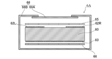
- FIG. 6 is a sectional view of the absorber 6A similar to that of FIG.
- the core wrap sheet 68 includes a first sheet 68A that covers the first non-woven fabric sheet 65 side, a widthwise end of the first non-woven fabric sheet 65, a side surface of the liquid diffusion layer 60, and a second non-woven fabric sheet 66. And a second sheet 68B covering the side.
- the first sheet 68A and the second sheet 68B are joined and integrated to wrap the entire absorbent composite.
- the core wrap sheet 68 for example, thin paper such as liquid-permeable tissue paper or non-woven fabric is used.
- the core wrap sheet 68 can diffuse the liquid discharged by the wearer throughout the absorber 6A.
- the core wrap sheet 68 may be composed of a single sheet.
- the absorber according to the second embodiment of the present invention will be described.
- the absorbent preferably holds the liquid distal to the wearer's skin.
- the SAP particles are fixed to the non-woven fabric base material, if the SAP particles necessary for absorbing and retaining a predetermined amount of liquid are arranged only on the back surface side of the base material that is distal from the wearer's skin, Since the SAP density on the side becomes too high, the SAP tends to cause gel blocking after absorbing the liquid.
- the SAP disposed on the surface of the nonwoven fabric substrate becomes a gel
- the liquid permeability on the surface side is reduced and the liquid diffuses throughout the absorber. And it causes liquid leakage. Therefore, it is required that the surface of the nonwoven fabric substrate in the absorbent body has both liquid absorbability and liquid permeability. Furthermore, if the SAP becomes gel and the amount of liquid retained decreases, the liquid once absorbed by the absorber will come back to the skin side of the wearer, which will cause a reversion.
- the present embodiment aims to provide a technique capable of suppressing liquid leakage and backflow.
- the liquid permeability of the upper SAP layer is increased and the liquid absorbability of the lower SAP layer is increased.
- the present embodiment is an absorber, which is formed of a non-woven fabric, and includes a substrate that is permeable to liquid, and an upper portion that is disposed on the surface of the substrate and that includes particles of SAP that is a superabsorbent polymer.
- An SAP layer and a lower SAP layer that is disposed on the back surface of the base material and that includes particles of SAP that is a superabsorbent polymer, and the upper SAP layer has a liquid permeability of 30 (ml/min) or more.
- the lower SAP layer has a liquid absorbency of 35 (g/g) or more.
- the upper SAP layer may be arranged on both sides in the width direction along the center portion in the width direction of the base material and may extend in the longitudinal direction of the base material.
- a groove may be formed on the front surface side of the base material so as to extend along the center portion in the width direction and along the upper SAP layers on both sides.
- the absorbent body may include a first nonwoven fabric sheet arranged so as to cover the front surface of the base material, and a second nonwoven fabric sheet arranged so as to cover the back surface of the base material.
- the absorbent body includes a core wrap sheet that covers the outer periphery of an absorbent composite including the base material, the upper SAP layer, the lower SAP layer, the first nonwoven fabric sheet, and the second nonwoven fabric sheet. May be.
- an absorbent article that absorbs the liquid discharged by the wearer, a liquid-impermeable backsheet, a liquid-permeable topsheet joined to the backsheet, the backsheet and the topsheet. And the above-mentioned absorber arranged between.
- FIG. 7 is a plan view of the absorber according to the second embodiment.
- the absorber 6 is formed in a sheet shape having a rectangular shape in a plan view.
- FIG. 7 shows a state in which the absorber 6 is viewed from the surface side, which is the skin facing surface side facing the wearer's skin when the absorber 6 is arranged in an absorbent article such as a diaper.
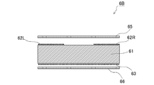
- FIG. 8 is a cross-sectional view of the absorbent body 6 taken along the line AA shown in FIG. 7 (a cross section taken along the width direction of the absorbent body 6 ).
- the absorber 6 has a uniform cross section in the entire longitudinal direction. It should be noted that in FIG. 8, gaps are provided between the constituent elements in order to make the constituent elements of the absorber 6 easy to understand, but in reality, almost no gap is formed between the constituent elements.
- the absorber 6 includes a base material 61.
- the base material 61 is formed in a rectangular sheet shape.
- As the base material 61 a bulky nonwoven fabric having a thickness of about 1 mm to 10 mm manufactured by an air-through method or a needle punch method is used.
- the base material 61 penetrates and diffuses the liquid.
- the absorber 6 is disposed on the surface of the base material 61, and is provided with SAP layers 62L and 62R (an example of “upper SAP layer”) including particles of SAP (Super Absorbent Polymer) that is a superabsorbent polymer.
- SAP Super Absorbent Polymer
- the front surface of the base material 61 is arranged on the skin facing surface side
- the back surface of the base material 61 is on the skin non-facing surface side opposite to the skin facing surface side. Will be placed.
- the SAP layers 62L and 62R are arranged on the front surface of the base material 61, on both sides in the width direction along the center portion of the base material 61 in the width direction, and extend in the longitudinal direction of the base material 61.
- the longitudinal direction of the base material 61 is orthogonal to the width direction of the base material 61.
- the SAP layer 62L is located on the left side of the wearer of the absorbent article, and the SAP layer 62R is located on the right side of the wearer of the absorbent article.
- the SAP layers 62L and 62R are formed by attaching a plurality of SAP particles to the surface of the base material 61 with an adhesive. In the SAP layers 62L and 62R, the SAP particles are arranged substantially uniformly.
- the base material 61 holds the SAP layers 62L and 62R.
- the SAP layers 62L and 62R extend over the entire longitudinal direction of the base material 61.
- the absorber 6 is disposed on the back surface of the base material 61, and includes the SAP layer 63 containing SAP particles (an example of a “lower SAP layer”).
- the SAP layer 63 is formed on substantially the entire back surface of the base material 61.
- the SAP layer 63 is formed by attaching a plurality of SAP particles to the back surface of the base material 61 with an adhesive. In the SAP layer 63, the SAP particles are arranged substantially uniformly.
- the base material 61 holds the SAP layer 63.
- the absorber 6 increases the liquid absorption and holding amount as a whole. Note that SAP particles may be included in the gaps in the base material 61.
- SAP absorbs 10 to 100 times its own weight of liquid.
- SAP for example, a granular material in a state before liquid absorption is used.
- the SAP layers 62L and 62R have higher liquid permeability than the SAP layer 63, and the SAP layer 63 has higher liquid absorbency than the SAP layers 62L and 62R. These can be set depending on the type of SAP arranged in each SAP layer.
- Liquid permeability is defined as the volume (ml) of liquid that permeates in 1 minute.
- a biocolumn having an inner diameter of 25.4 mm (Biocolumn CF-30K etc. manufactured by AS ONE Co., Ltd.) equipped with a filter (Biocolumn filter 30SUS manufactured by AS ONE Co., Ltd.) is prepared.
- Biocolumn filter 30SUS manufactured by AS ONE Co., Ltd. those with marks on the liquid volumes of 60 ml and 40 ml, or those with marks on the liquid volumes of 60 ml and 40 ml are used.
- the cock of the biocolumn is opened, the liquid level is lowered until the liquid level in the biocolumn tube is about 5 cm above the 60 ml line, and the state is waited for 1 minute.
- the cock of the biocolumn is opened, and the time (T1) required for the liquid level to drop from the 60 ml line to the 40 ml line is measured.
- the same test is performed with no SAP, and the time (T0) is measured.
- a SAP having a liquid permeability of 30 (ml/min) or more is used for the SAP layers 62L and 62R. Therefore, the SAP layers 62L and 62R have a liquid permeability of 30 (ml/min) or more.
- the SAP layer 63 has a liquid permeability lower than 30 (ml/min).
- the liquid absorbency is defined by the amount (g) of liquid absorbed per 1 g of SAP.
- a nylon sheet with an opening of 57 ⁇ m is cut into a size of 10 cm in length and 40 cm in width, the cut nylon sheet is folded in half in the longitudinal direction, and both ends are heat-sealed to form a bag of 10 cm ⁇ 20 cm to form a nylon bag.
- To do. Put 1.00 g ( ⁇ 0.01 g) of SAP in this nylon bag. Then, the nylon bag is placed in a physiological saline solution having a concentration of 0.900% ( ⁇ 0.009%) and a temperature of 25° C. ( ⁇ 2° C.) and immersed for 1 hour.
- the nylon bag is pulled up and drained for 15 minutes. Then, the centrifugal force is set to 150 G with a centrifugal dehydrator, dehydration is performed for 90 seconds, and the weight (A) of the nylon bag is measured. Also, a similar nylon bag containing no SAP is prepared and the same test is performed to measure the weight (B) of the nylon bag.
- the SAP layer 63 is made of SAP having a liquid absorbency of 35 (g/g) or more. Therefore, the SAP layer 63 has a liquid absorbency of 35 (g/g) or more.
- the SAP layers 62L and 62R have a liquid absorbency smaller than 35 (g/g).
- the SAP closer to the wearer's skin absorbs a larger amount of urine. Therefore, after the absorbent absorbs urine a plurality of times, the SAP closer to the wearer's skin swells and the liquid permeability decreases, and the inside of the absorbent and the non-skin-facing surface side (lower side) are absorbed. It is difficult for urine to enter, and this urine may flow on the skin-facing surface side of the absorbent body and leak.
- the SAP layers 62L and 62R are located on the skin facing surface side, and the SAP layer 63 is located on the skin non-facing surface side.
- the SAP layer 63 is arranged more distal to the wearer's skin than the SAP layers 62L and 62R.
- the SAP layers 62L and 62R have a liquid permeability of 30 (ml/min) or more. Therefore, the absorbent body 6 ensures the liquid permeability of the SAP layers 62L and 62R arranged closer to the wearer's skin even after absorbing the urine a plurality of times, and the inside of the base material 61 and the SAP layer are secured.
- the SAP layer 63 has a liquid absorbency of 35 (g/g) or more. Since the absorbent body 6 according to the present embodiment holds a relatively large amount of urine in the SAP layer 63 disposed distally from the wearer's skin, it suppresses the feeling of wetting the skin surface and suppresses the deterioration of the feeling of wearing. it can.
- SAP layers are arranged on the front surface and the back surface of the base material 61, and SAP required for absorbing and retaining a predetermined amount of liquid may be separately arranged in the SAP layers 62L, 62R, 63.
- the absorbent body 6 can prevent the SAP in the SAP layers 62L, 62R, 63 from being gelled, and can prevent the SAP layers 62L, 62R, 63 from absorbing and holding the liquid, thereby preventing the SAP from being absorbed once. It is possible to prevent the liquid from returning to the skin side of the wearer.
- SAP is not provided in the central portion in the width direction, and SAP layers 62L and 62R are arranged on both sides in the width direction.
- the central portion in the front side width direction of the base material 61 is arranged at a position facing the urethral opening (hereinafter, referred to as “urethral opening facing position”) when the absorbent body 6 is arranged on the absorbent article.
- urethral opening facing position a position facing the urethral opening
- the SAP layer may be formed on the entire surface of the base material 61.
- the absorber 6 also includes a first nonwoven fabric sheet 65 arranged to cover the front surface of the base material 61 and a second nonwoven fabric sheet 66 arranged to cover the back surface of the base material 61.
- a liquid-permeable nonwoven fabric is used for the first nonwoven fabric sheet 65 and the second nonwoven fabric sheet 66.
- air-laid non-woven fabric is used for the first non-woven fabric sheet 65 and the second non-woven fabric sheet 66.
- the first nonwoven fabric sheet 65 and the second nonwoven fabric sheet 66 diffuse the liquid in the width direction and the longitudinal direction of the absorber 6.
- the absorbent body 6 prevents liquid such as urine discharged by the wearer from being concentrated in the widthwise center or the longitudinal center of the absorbent body 6.
- the wearer's feeling of wearing the absorbent article can be improved.
- FIG. 9 is a plan view similar to FIG. 7.
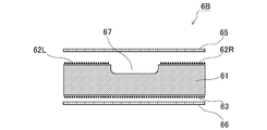
- FIG. 10 is a cross-sectional view when cut along the BB cross section (cross section along the width direction of the absorber 6) shown in FIG. 9.
- a groove 67 is formed in the center portion in the width direction of the base material 61 and along the SAP layers 62L and 62R on both sides. The groove 67 is formed at a position facing the urethral opening so that the urine excreted by the wearer can easily flow in when the absorbent body 6 is arranged in the absorbent article.
- the groove 67 is formed by pressing the groove forming region from the front surface side of the base material 61 after the base material 61 is formed.
- the groove 67 may be formed by reducing the basis weight of the non-woven fabric in the groove forming region when the base material 61 is manufactured.
- FIG. 11 is a cross-sectional view of the absorber 6 similar to FIG.
- the core wrap sheet 68 includes a first sheet 68A that covers the first non-woven fabric sheet 65 side, a widthwise end of the first non-woven fabric sheet 65, a side surface of the base material 61, and a second non-woven fabric sheet 66 side. And a second sheet 68B that covers the.
- the first sheet 68A and the second sheet 68B are joined and integrated to wrap the entire absorbent composite.
- the core wrap sheet 68 for example, thin paper such as liquid-permeable tissue paper or non-woven fabric is used.
- the core wrap sheet 68 can diffuse the liquid discharged by the wearer throughout the absorbent body 6.
- the core wrap sheet 68 may be composed of a single sheet.
- the absorbent preferably holds the liquid distal to the wearer's skin.
- the SAP particles are fixed to the non-woven fabric base material, if the SAP particles necessary for absorbing and retaining a predetermined amount of liquid are arranged only on the back surface side of the base material that is distal from the wearer's skin, Since the SAP density on the side becomes too high, the SAP tends to cause gel blocking after absorbing the liquid.
- the SAP disposed on the surface of the nonwoven fabric substrate becomes a gel
- the liquid permeability on the surface side is reduced and the liquid diffuses throughout the absorber. And it causes liquid leakage. Therefore, it is required that the surface of the nonwoven fabric substrate in the absorbent body has both liquid absorbability and liquid permeability. Furthermore, if the SAP becomes gel and the amount of liquid retained decreases, the liquid once absorbed by the absorber will come back to the skin side of the wearer, which will cause a reversion.
- the present embodiment has an object to provide a technique capable of suppressing liquid leakage and backflow.
- the upper SAP layer has a smaller amount of SAP than the lower SAP layer.
- the present embodiment is an absorber, which is formed of a non-woven fabric, and includes a substrate that is permeable to liquid, and an upper portion that is disposed on the surface of the substrate and that includes particles of SAP that is a superabsorbent polymer.
- An SAP layer and a lower SAP layer disposed on the back surface of the base material and including particles of SAP that is a superabsorbent polymer, wherein the upper SAP layer has a lower amount of SAP than the lower SAP layer. ..
- the upper SAP layer is arranged on both sides in the width direction along the center portion in the width direction of the base material, extends in the longitudinal direction of the base material, and is provided on the front surface side of the base material. May have a groove formed in the center portion in the width direction and along the upper SAP layers on both sides.
- the upper SAP layer may have higher liquid permeability than the lower SAP layer.
- the absorbent body may include a first nonwoven fabric sheet arranged so as to cover the front surface of the base material, and a second nonwoven fabric sheet arranged so as to cover the back surface of the base material.
- the absorbent body includes a core wrap sheet that covers the outer periphery of an absorbent composite including the base material, the upper SAP layer, the lower SAP layer, the first nonwoven fabric sheet, and the second nonwoven fabric sheet. May be.
- the absorber may include a squeeze groove formed by compressing the core wrap sheet, the first nonwoven fabric sheet and the base material.
- an absorbent article that absorbs the liquid discharged by the wearer, a liquid-impermeable backsheet, a liquid-permeable topsheet joined to the backsheet, the backsheet and the topsheet. And the absorber disposed between the two.
- the absorbent article may include a squeeze groove formed by compressing a part of the base material of the absorber from the top sheet.
- FIG. 12 is a plan view of the absorber according to the third embodiment.
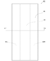
- the absorber 6C is formed in a sheet shape having a rectangular shape in a plan view.
- FIG. 12 shows a state in which the absorber 6C is viewed from the surface side which is the skin facing surface side facing the wearer's skin when the absorber 6C is arranged in an absorbent article such as a diaper.
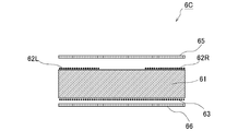
- FIG. 13 is a cross-sectional view of the absorber 6C taken along the line AA shown in FIG. 12 (cross section along the width direction of the absorber 6C).
- the absorber 6C has a uniform cross section in the entire longitudinal direction. Note that, in FIG. 13, gaps are provided between the constituent elements for easy understanding of the constituent elements of the absorber 6C, but in reality, almost no gap is formed between the constituent elements.
- the absorber 6C includes a base material 61.
- the base material 61 is formed in a rectangular sheet shape.
- As the base material 61 a bulky nonwoven fabric having a thickness of about 1 mm to 10 mm manufactured by an air-through method or a needle punch method is used.
- the base material 61 penetrates and diffuses the liquid.
- the absorber 6C is disposed on the surface of the base material 61, and is provided with SAP layers 62L and 62R (an example of “upper SAP layer”) including particles of SAP (Super Absorbent Polymer) that is a superabsorbent polymer.
- SAP Super Absorbent Polymer
- the front surface of the base material 61 is arranged on the skin-facing surface side
- the back surface of the base material 61 is on the skin-non-facing surface side opposite to the skin-facing surface side. Will be placed.
- the SAP layers 62L and 62R are arranged on the front surface of the base material 61, on both sides in the width direction along the center portion of the base material 61 in the width direction, and extend in the longitudinal direction of the base material 61.
- the longitudinal direction of the base material 61 is orthogonal to the width direction of the base material 61.
- the SAP layer 62L is located on the left side of the wearer of the absorbent article, and the SAP layer 62R is located on the right side of the wearer of the absorbent article.
- the SAP layers 62L and 62R are formed by attaching a plurality of SAP particles to the surface of the base material 61 with an adhesive. In the SAP layers 62L and 62R, the SAP particles are arranged substantially uniformly.
- the base material 61 holds the SAP layers 62L and 62R.
- the SAP layers 62L and 62R extend over the entire longitudinal direction of the base material 61.
- the absorber 6C is disposed on the back surface of the base material 61 and includes the SAP layer 63 containing SAP particles (an example of a “lower SAP layer”).
- the SAP layer 63 is formed on substantially the entire back surface of the base material 61.
- the SAP layer 63 is formed by attaching a plurality of SAP particles to the back surface of the base material 61 with an adhesive. In the SAP layer 63, the SAP particles are arranged substantially uniformly.
- the base material 61 holds the SAP layer 63.
- the absorber 6C increases the liquid absorption and holding amount as a whole. Note that SAP particles may be included in the gaps in the base material 61.
- SAP absorbs 10 to 100 times its own weight of liquid.
- SAP for example, a granular material in a state before liquid absorption is used.
- the SAP layers 62L and 62R have a smaller amount of SAP than the SAP layer 63.
- the liquid absorption amount (liquid holding amount) in the SAP layer is proportional to the amount of SAP.
- the absorber 6C according to the present embodiment is provided with the SAP layer 63 containing a larger amount of SAP than the SAP layers 62L and 63R, and thus suppresses liquid leakage without reducing the liquid absorption and retention amount as a whole. it can.
- the absorbent body 6C has the SAP layers 62L and 62R having a smaller amount of SAP than the SAP layer 63, so that the SAP layer 62L is disposed proximally from the wearer's skin when disposed in the absorbent article.
- the amount of SAP in the SAP layer may be defined by the basis weight or the amount of application (g).
- the SAP layers 62L and 62R may have higher liquid permeability than the SAP layer 63. These can be set depending on the type of SAP arranged in each SAP layer. Liquid permeability is defined as the volume (ml) of liquid that permeates in 1 minute.
- a biocolumn having an inner diameter of 25.4 mm (Biocolumn CF-30K etc. manufactured by AS ONE Co., Ltd.) equipped with a filter (Biocolumn filter 30SUS manufactured by AS ONE Co., Ltd.) is prepared.
- Biocolumn filter 30SUS manufactured by AS ONE Co., Ltd. those with marks on the liquid volumes of 60 ml and 40 ml, or those with marks on the liquid volumes of 60 ml and 40 ml are used.
- the cock of the biocolumn is opened, the liquid level is lowered until the liquid level in the biocolumn tube is about 5 cm above the 60 ml line, and the state is waited for 1 minute.
- the cock of the biocolumn is opened, and the time (T1) required for the liquid level to drop from the 60 ml line to the 40 ml line is measured.
- the same test is performed with no SAP, and the time (T0) is measured.
- SAP having a liquid permeability of 30 (ml/min) or more may be used.
- the SAP layers 62L and 62R have a liquid permeability of 30 (ml/min) or more than that of the SAP layer 63.
- the SAP layer 63 has a liquid permeability lower than 30 (ml/min).
- the SAP closer to the wearer's skin absorbs a larger amount of urine. Therefore, after the absorbent absorbs urine a plurality of times, the SAP closer to the wearer's skin swells and the liquid permeability decreases, and the inside of the absorbent and the non-skin-facing surface side (lower side) are absorbed. It is difficult for urine to enter, and this urine may flow on the skin-facing surface side of the absorbent body and leak.
- the SAP layers 62L and 62R are located on the skin facing surface side, and the SAP layer 63 is located on the skin non-facing surface side.
- the SAP layer 63 is arranged more distal to the wearer's skin than the SAP layers 62L and 62R.
- the SAP layers 62L and 62R have higher liquid permeability than the SAP layer 63. Therefore, the absorber 6C ensures the liquid permeability of the SAP layers 62L and 62R arranged closer to the wearer's skin even after absorbing the urine a plurality of times, and the inside of the base material 61 and the SAP layer are secured.
- SAP layers are arranged on the front surface and the back surface of the base material 61, and SAP required for absorbing and retaining a predetermined amount of liquid can be separately arranged in the SAP layers 62L, 62R, 63. Therefore, it is possible to prevent the SAP density in the SAP layers 62L, 62R, 63 from becoming too high, and prevent gel blocking from occurring. Further, the absorbent body 6C can prevent the SAP in the SAP layers 62L, 62R, 63 from being gelled, and can prevent the SAP layers 62L, 62R, 63 from decreasing in the amount of liquid absorbed and retained, thereby temporarily absorbing the liquid. It is possible to prevent the liquid from returning to the skin side of the wearer.
- SAP is not provided in the central portion in the width direction, and SAP layers 62L and 62R are arranged on both sides in the width direction.
- the front side widthwise central portion of the base material 61 is arranged at a position facing the urethral opening (hereinafter referred to as “urethral opening facing position”) when the absorbent body 6C is arranged on the absorbent article.
- urethral opening facing position a position facing the urethral opening
- the SAP is not provided at the position facing the urethral meatus, so that the discharged urine can be introduced into the base material 61 and diffused throughout.
- the SAP layer may be formed on the entire surface of the base material 61.
- the absorbent body 6C has a large liquid permeability of the SAP layer arranged closer to the wearer's skin as described above, urine easily enters the inside of the base material 61 and the SAP layer 63. Then, the leakage of this urine can be suppressed.
- the absorber 6C also includes a first nonwoven fabric sheet 65 arranged to cover the front surface of the base material 61 and a second nonwoven fabric sheet 66 arranged to cover the back surface of the base material 61.
- a liquid-permeable nonwoven fabric is used for the first nonwoven fabric sheet 65 and the second nonwoven fabric sheet 66.
- air-laid non-woven fabric is used for the first non-woven fabric sheet 65 and the second non-woven fabric sheet 66.
- the first nonwoven fabric sheet 65 and the second nonwoven fabric sheet 66 diffuse the liquid in the width direction and the longitudinal direction of the absorber 6C.
- the absorber 6C prevents the liquid such as urine discharged by the wearer from concentrating on the center in the width direction or the center in the longitudinal direction of the absorber 6C. Further, by providing the first nonwoven fabric sheet 65, the wearer's feeling of wearing the absorbent article can be improved.
- the base material 61 may have grooves formed therein.
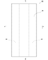
- FIG. 14 is a plan view similar to FIG.
- FIG. 15 is a cross-sectional view when cut along the BB cross section (cross section along the width direction of the absorber 6C) shown in FIG.
- a groove 67 is formed in the center portion in the width direction of the base material 61 and along the SAP layers 62L and 62R on both sides.
- the groove 67 is formed at a position opposite to the urethral opening so that the urine excreted by the wearer can easily flow in when the absorber 6C is arranged in the absorbent article.
- the groove 67 is formed by pressing the groove forming region from the front surface side of the base material 61 after the base material 61 is formed.
- the groove 67 may be formed by reducing the basis weight of the non-woven fabric in the groove forming region when the base material 61 is manufactured.
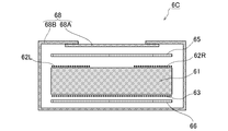
- FIG. 16 is a sectional view of the absorber 6C similar to that of FIG.
- the core wrap sheet 68 includes a first sheet 68A that covers the first non-woven fabric sheet 65 side, a widthwise end of the first non-woven fabric sheet 65, a side surface of the base material 61, and a second non-woven fabric sheet 66 side. And a second sheet 68B that covers the.
- the first sheet 68A and the second sheet 68B are joined and integrated to wrap the entire absorbent composite.
- the core wrap sheet 68 for example, thin paper such as liquid-permeable tissue paper or non-woven fabric is used.
- the core wrap sheet 68 can diffuse the liquid discharged by the wearer throughout the absorber 6C.
- the core wrap sheet 68 may be composed of a single sheet.
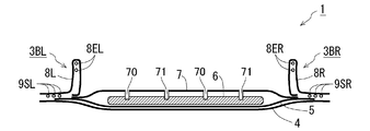
- FIG. 17 is a plan view of the absorbent core 6C seen from the first sheet 68a side of the core wrap sheet 68 shown in FIG.
- the first sheet 68a is placed on the skin facing surface side.
- Compressed grooves 70 and 71 are formed on the surface of the first sheet 68a.
- the compressed grooves 70 and 71 are formed in a plurality of straight lines that are inclined with respect to the longitudinal direction of the absorber 6C.
- a plurality of compression grooves 70 extend from the upper left to the lower right of the absorbent body 6C toward the paper surface and are formed in parallel to each other. Further, a plurality of compressed grooves 71 extend from the upper right side to the lower left side of the absorbent body 6C toward the paper surface and are formed in parallel to each other. The compressed groove 70 and the compressed groove 71 intersect at a substantially right angle. These compressed grooves 70, 71 are formed in a grid pattern as a whole.
- the formation pattern of the compressed grooves 70, 71 is not limited to this, and may be formed, for example, so as to extend along the longitudinal direction of the absorber 6C, or may be formed in a curved shape. ..
- FIG. 18 is a cross-sectional view when cut along the CC cross section (cross section along the width direction of the absorber 6C) shown in FIG.
- the compressed grooves 70, 71 are formed by compressing the core wrap sheet 68, the first nonwoven fabric sheet 65 and the base material 61. Further, the compressed grooves 70, 71 are formed to a depth that reaches a part of the base material 61 from the front surface side of the absorber 6C.
- the absorber 6C allows air to flow into the compressed grooves 70 and 71 to improve liquid permeability. Further, since the liquid flows in the compression grooves 70, 71, the diffusibility of the liquid is improved. In this way, the compressed grooves 70, 71 are provided to improve the liquid permeability and the liquid diffusivity of the absorber 6C.
- the compression grooves 70 and 71 are compressed by compressing the core wrap sheet 68 and the first nonwoven fabric sheet 65 toward the surface of the base material 61 by passing the absorber 6C through a press roll having a convex grid pattern. It is formed by being processed.
- the SAP layer when the SAP layer is formed on the surface of the base material 61, the SAP may break the core wrap sheet or the non-woven fabric sheet when the compression processing is performed from the surface side of the absorber 6C.
- the absorber 6C according to the present embodiment, the amount of SAP in the SAP layers 62L and 62R arranged on the surface side of the absorber 6C is reduced.
- the absorber 6C can improve the yield when the compression processing is performed.
- the present embodiment aims to provide a technique capable of suppressing liquid leakage.
- a water repellent processed area is provided on the surface of the base material, centering on the urethral opening facing the wearer's urethral opening.
- the present embodiment is an absorber, a base material formed of a non-woven fabric, an SAP layer disposed on the front and back surfaces of the base material, and containing SAP particles that are a superabsorbent polymer,
- the surface of the base material is provided with a water-repellent processed region centered on the urethral opening facing the wearer's urethral opening.
- the water repellent processed area may be provided so that the water repellency decreases as the distance from the urethral opening facing position increases.
- water-repellent processed regions are arranged alternately with the non-water-repellent processed regions in the longitudinal direction of the base material, and the ratio of the water-repellent processed region to the non-water-repellent processed region per unit area gradually increases. It may be provided so as to be small.
- a groove extending in the longitudinal direction of the base material may be formed on the front surface side of the base material and in the central portion in the width direction of the base material.
- the absorbent body may include a first nonwoven fabric sheet arranged so as to cover the front surface of the base material, and a second nonwoven fabric sheet arranged so as to cover the back surface of the base material.
- the absorbent body may include a core wrap sheet that covers the outer periphery of the absorbent composite including the base material, the SAP layer, the first nonwoven fabric sheet, and the second nonwoven fabric sheet.
- an absorbent article that absorbs urine discharged by the wearer, a liquid-impermeable backsheet, a liquid-permeable topsheet joined to the backsheet, the backsheet and the topsheet.
- the absorbent body according to any one of the above, which is disposed between the two.
- liquid leakage can be suppressed.
- FIG. 19 is a plan view of the absorber according to the fourth embodiment.
- the absorber 6D is formed in a sheet shape having a rectangular shape in a plan view.
- FIG. 19 shows a state in which the absorber 6D is viewed from the surface side which is the skin facing surface side facing the wearer's skin when the absorber 6D is arranged in an absorbent article such as a diaper.
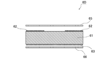
- FIG. 20 is a cross-sectional view of the absorbent body 6D taken along the line AA shown in FIG. 19 (cross section taken along the width direction of the absorbent body 6D).
- the absorber 6D has a uniform cross section in the entire longitudinal direction. Note that, in FIG. 20, gaps are provided between the constituent elements in order to facilitate understanding of the constituent elements of the absorber 6D, but in reality, almost no gap is formed between the constituent elements.
- the absorber 6D includes a base material 61.
- the base material 61 is formed in a rectangular sheet shape.
- As the base material 61 a bulky nonwoven fabric having a thickness of about 1 mm to 3 mm manufactured by an air-through method or a needle punch method is used.
- the absorber 6D is disposed on the front surface and the back surface of the base material 61, and is provided with a SAP layer containing particles of SAP (Super Absorbent Polymer) that is a superabsorbent polymer.
- SAP Super Absorbent Polymer
- the front surface of the base material 61 is arranged on the skin facing surface side
- the back surface of the base material 61 is on the skin non-facing surface side opposite to the skin facing surface side. Will be placed.
- the SAP layer 62 is arranged on the front surface of the base material 61
- the SAP layer 63 is arranged on the rear surface of the base material 61.
- the SAP layer 62 is formed by attaching a plurality of SAP particles to the surface of the base material 61 with an adhesive.
- the SAP layer 63 is formed by attaching a plurality of SAP particles to the back surface of the base material 61 with an adhesive.
- the SAP particles are arranged substantially uniformly.
- the base material 61 holds the SAP layers 62 and 63.
- the SAP layer 62 is arranged over the entire front surface side longitudinal direction of the base material 61.
- the SAP layer 63 is arranged on substantially the entire back surface of the base material 61. Note that SAP particles may be included in the gaps in the base material 61.
- SAP absorbs 10 to 100 times its own weight of liquid.
- SAP for example, a granular material in a state before liquid absorption is used.
- the SAP layers 62 and 63 absorb and hold the liquid diffused by the base material 61.
- the SAP layers 62 arranged on the surface of the base material 61 are arranged on both sides in the width direction of the base material 61 along the longitudinal direction of the base material 61.
- the urethral opening facing position which is the position facing the wearer's urethral opening, is arranged in the widthwise central portion of the base material 61. Therefore, if the SAP layers 62 are thus arranged on both sides in the width direction of the base material 61 along the longitudinal direction of the base material 61, urine excreted from the wearer is absorbed into the SAP layer 62 via the base material 61. Or, it is easily absorbed into the SAP layer 63 via the base material 61.
- the absorbent body 6D includes a first non-woven fabric sheet 65 arranged so as to cover the surface of the base material 61 and a second non-woven fabric sheet 66 arranged so as to cover the back surface of the base material 61.
- a liquid-permeable nonwoven fabric is used for the first nonwoven fabric sheet 65 and the second nonwoven fabric sheet 66.
- air-laid non-woven fabric is used for the first non-woven fabric sheet 65 and the second non-woven fabric sheet 66.
- the first nonwoven fabric sheet 65 and the second nonwoven fabric sheet 66 diffuse the liquid in the width direction and the longitudinal direction of the absorber 6D.
- the absorber 6D prevents the liquid discharged by the wearer from concentrating on the center of the absorber 6D in the width direction and the center of the absorber 6D in the longitudinal direction. Further, by providing the first nonwoven fabric sheet 65, the wearer's feeling of wearing the absorbent article can be improved.
- a groove may be formed in the base material 61.
- 21 is a cross-sectional view of the absorber 6D similar to FIG.
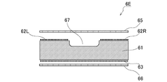
- a groove 67 extending in the longitudinal direction of the base material 61 is formed on the front surface side of the base material 61 and in the central portion in the width direction of the base material 61.
- the groove 67 is formed at a position facing the urethral opening so that the urine excreted by the wearer can easily flow in when the absorber 6D is arranged in the absorbent article.
- the groove 67 is formed by pressing the groove forming region from the front surface side of the base material 61 after the base material 61 is formed.
- the groove 67 may be formed by reducing the basis weight of the non-woven fabric in the groove forming region when the base material 61 is manufactured.
- the groove 67 immediately guides the liquid excreted from the wearer's urethral opening to the outside of the urethral opening facing position, and diffuses this liquid to the base material 61 in the region other than the urethral opening facing position.
- the absorber 6D can suppress lateral leakage of the liquid that leaks from the side surface of the base material 61.
- the surface of the base material 61 is treated to be water repellent.
- the water-repellent treatment means that the surface of the base material 61 is repelled by liquid, and the liquid is less likely to flow from the surface of the base material 61 into the base material 61 at the processed part.
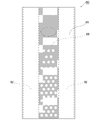
- FIG. 22 is a diagram showing a first example of a portion that is water repellent.
- the part surrounded by the alternate long and short dash line indicates the position facing the urethral meatus.
- the water repellency is highest near the urethral-opposite position on the surface of the base material 61, and gradually increases as the distance from the urethral-opposite position increases. The water repellency is reduced. That is, in the present embodiment, for example, as shown by hatching in FIG.
- the largest water-repellent processed area 69 is provided at the position facing the urethral meatus, and the non-water-repellent processed area not subjected to the water-repellent processing is provided.
- the water treatment regions 69 are alternately provided such that the area of the water repellent treatment regions 69 per unit area gradually decreases as the distance from the urethral orifice facing position increases. Therefore, in the example shown in FIG. 22, it can be said that the water-repellent processed area 69 is formed so as to draw a striped pattern along the longitudinal direction of the base material 61.
- the water-repellent treatment centering on the urethral-opposite position is not a concept intended to precisely decrease the water-repellent property from the urethral-opposite position as a strict central position, but mainly This is a concept that includes a water-repellent treatment in which the water repellency near the urethral orifice is slightly higher than the other.
- the water repellent finish is not limited to the striped water repellent finish region 69 as shown in FIG. 22, as long as the urine excreted by the wearer is diffused over the entire base material 61.
- the water-repellent treatment is continuously performed along the longitudinal direction of the base material 61, and the water-repellent force is highest near the urethral-mouth facing position, and gradually decreases as the distance from the urethral-mouth facing position increases.
- the size of the non-water-repellent regions discretely provided in the water-repellent region may be gradually increased with increasing distance from the urethral-opposite position.
- FIG. 23 is a diagram showing a second example of a portion that has been subjected to water repellent finishing.
- the water repellent treatment is performed along the longitudinal direction of the base material 61, and even if the non-water repellent region is provided in the water repellent treated region 69 like a polka dot pattern. Good.
- the water-repellent treatment can be realized, for example, by subjecting the surface of the base material 61 to physical treatment such as heat treatment or pressure treatment, or by performing chemical treatment such as application of water-repellent ink.
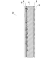
- FIG. 24 is a cross-sectional view of the absorbent body 6D taken along the line BB shown in FIG. 19 (cross section taken along the longitudinal direction of the absorbent body 6D).
- a white arrow shows how the water excreted from the urethral meatus flows.
- the surface of the base material 61 is subjected to the water repellent treatment for diffusing the urine excreted by the wearer over the entire base material 61, it is excreted from the urethral opening of the wearer. As shown by the outline arrow in FIG.
- the liquid does not diffuse into the base material 61 in the vicinity of the urethral opening facing position, and is guided to a position on the surface of the base material 61 away from the urethral opening facing position. In the water repellent area, this liquid is diffused over the entire base material 61.
- the liquid diffused from the surface of the base material 61 to the entire base material 61 through the non-water-repellent region is the SAP layer 62 provided on the front surface of the base material 61 or the SAP provided on the back surface of the base material 61. It is absorbed by the layer 63. As a result, the absorber 6D can suppress lateral leakage of the liquid that leaks from the side surface of the base material 61.
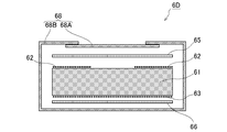
- FIG. 25 is sectional drawing of the absorber 6D similar to FIG.
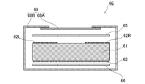
- the core wrap sheet 68 includes a first sheet 68A that covers the first non-woven fabric sheet 65, a widthwise end portion of the first non-woven fabric sheet 65, a side surface of the base material 61, and a second non-woven fabric sheet 66 side. And a second sheet 68B for covering.
- the first sheet 68A and the second sheet 68B are joined and integrated to wrap the entire absorbent composite.
- the core wrap sheet 68 for example, thin paper such as liquid-permeable tissue paper or non-woven fabric is used.
- the core wrap sheet 68 can diffuse the liquid discharged by the wearer throughout the absorber 6D.
- the core wrap sheet 68 may be composed of a single sheet.
- the present embodiment has an object to provide a technique capable of suppressing liquid leakage and backflow.
- the liquid absorption rate of the upper SAP layer is high, and the liquid absorbability of the lower SAP layer is increased.
- the present embodiment is an absorber, which is formed of a non-woven fabric, and includes a substrate that is permeable to liquid, and an upper portion that is disposed on the surface of the substrate and that includes particles of SAP that is a superabsorbent polymer.
- An SAP layer and a lower SAP layer disposed on the back surface of the substrate and containing particles of SAP that is a superabsorbent polymer, and a liquid absorption rate of 45 (sec) measured by the upper SAP layer vortex method.
- the liquid absorption property of the lower SAP layer is 35 (g/g) or more.
- the upper SAP layer may be arranged on both sides in the width direction along the center portion in the width direction of the base material and may extend in the longitudinal direction of the base material.
- a groove may be formed on the front surface side of the base material so as to extend along the center portion in the width direction and along the upper SAP layers on both sides.
- the absorbent body may include a first nonwoven fabric sheet arranged so as to cover the front surface of the base material, and a second nonwoven fabric sheet arranged so as to cover the back surface of the base material.
- the absorbent body includes a core wrap sheet that covers the outer periphery of an absorbent composite including the base material, the upper SAP layer, the lower SAP layer, the first nonwoven fabric sheet, and the second nonwoven fabric sheet. May be.
- an absorbent article that absorbs the liquid discharged by the wearer, a liquid-impermeable backsheet, a liquid-permeable topsheet joined to the backsheet, the backsheet and the topsheet. And the above-mentioned absorber arranged between.
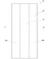
- FIG. 26 is a plan view of the absorber according to the fifth embodiment.
- the absorber 6E is formed in a sheet shape having a rectangular shape in a plan view.
- FIG. 26 shows a state in which the absorber 6E is viewed from the surface side, which is the skin-facing surface side facing the wearer's skin when the absorber 6E is arranged in an absorbent article such as a diaper.
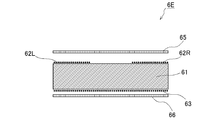
- FIG. 27 is a cross-sectional view of the absorbent body 6E taken along the line AA shown in FIG. 26 (cross section taken along the width direction of the absorbent body 6E).
- the absorber 6E has a uniform cross section in the entire longitudinal direction. Note that, in FIG. 27, gaps are provided between the constituent elements in order to make the constituent elements of the absorber 6E easy to understand, but in reality, almost no gap is formed between the constituent elements.
- the absorber 6E includes a base material 61.
- the base material 61 is formed in a rectangular sheet shape.
- As the base material 61 a bulky nonwoven fabric having a thickness of about 1 mm to 10 mm manufactured by an air-through method or a needle punch method is used.
- the base material 61 penetrates and diffuses the liquid.
- the absorber 6E is disposed on the surface of the base material 61 and includes SAP layers 62L and 62R (an example of “upper SAP layer”) including particles of SAP (Super Absorbent Polymer) that is a superabsorbent polymer.
- SAP Super Absorbent Polymer
- the front surface of the base material 61 is arranged on the skin-facing surface side
- the back surface of the base material 61 is on the skin-non-facing surface side opposite to the skin-facing surface side. Will be placed.
- the SAP layers 62L and 62R are arranged on the front surface of the base material 61, on both sides in the width direction along the center portion of the base material 61 in the width direction, and extend in the longitudinal direction of the base material 61.
- the longitudinal direction of the base material 61 is orthogonal to the width direction of the base material 61.
- the SAP layer 62L is located on the left side of the wearer of the absorbent article, and the SAP layer 62R is located on the right side of the wearer of the absorbent article.
- the SAP layers 62L and 62R are formed by attaching a plurality of SAP particles to the surface of the base material 61 with an adhesive. In the SAP layers 62L and 62R, the SAP particles are arranged substantially uniformly.
- the base material 61 holds the SAP layers 62L and 62R.
- the SAP layers 62L and 62R extend over the entire longitudinal direction of the base material 61.
- the absorber 6E is disposed on the back surface of the base material 61 and includes the SAP layer 63 containing SAP particles (an example of a “lower SAP layer”).
- the SAP layer 63 is formed on substantially the entire back surface of the base material 61.
- the SAP layer 63 is formed by attaching a plurality of SAP particles to the surface of the base material 61 with an adhesive. In the SAP layer 63, the SAP particles are arranged substantially uniformly.
- the base material 61 holds the SAP layer 63.
- the absorber 6E increases the liquid absorption and holding amount as a whole. Note that SAP particles may be included in the gaps in the base material 61.
- SAP absorbs 10 to 100 times its own weight of liquid.
- SAP for example, a granular material in a state before liquid absorption is used.
- the SAP layers 62L and 62R have a higher liquid absorption speed than the SAP layer 63, and the SAP layer 63 has a higher liquid absorption property than the SAP layers 62L and 62R. These can be set depending on the type of SAP arranged in each SAP layer.
- the liquid absorption rate of SAP can be measured by the vortex method.
- 50.0 ml ( ⁇ 0.5 ml) of physiological saline having a concentration of 0.900% ( ⁇ 0.009%) and a temperature of 25° C. ( ⁇ 2° C.) is placed in a beaker having a volume of 100 ml.
- the stirrer bar is rotated at 600 rpm ( ⁇ 30 rpm), and it is confirmed that the physiological saline in the beaker stably forms a vortex.
- measurement was started with a stopwatch, and the time until the vortex disappeared and the liquid surface became horizontal was measured.
- the liquid absorption rate of SAP is obtained by the vortex method described above.
- SAP whose liquid absorption rate measured by the vortex method is 45 (sec) or less is used. Therefore, the SAP layers 62L and 62R have a liquid absorption rate of 45 (sec) or less measured by the vortex method.
- the SAP layer 63 has a liquid absorption rate of greater than 45 (sec) measured by the vortex method.
- the liquid absorbency is defined by the amount (g) of liquid absorbed per 1 g of SAP.
- a nylon sheet with an opening of 57 ⁇ m is cut into a size of 10 cm in length and 40 cm in width, the cut nylon sheet is folded in half in the longitudinal direction, and both ends are heat-sealed to form a bag of 10 cm ⁇ 20 cm to form a nylon bag.
- To do. Put 1.00 g ( ⁇ 0.01 g) of SAP in this nylon bag. Then, the nylon bag is placed in a physiological saline solution having a concentration of 0.900% ( ⁇ 0.009%) and a temperature of 25° C. ( ⁇ 2° C.) and immersed for 1 hour.
- the nylon bag is pulled up and drained for 15 minutes. Then, the centrifugal force is set to 150 G with a centrifugal dehydrator, dehydration is performed for 90 seconds, and the weight (A) of the nylon bag is measured. Also, a similar nylon bag containing no SAP is prepared and the same test is performed to measure the weight (B) of the nylon bag.
- liquid absorbency of SAP is determined by applying the values of A and B obtained by the above test to the following equation (4).
- Liquid absorbency (g/g) (AB)/SAP collection amount...(4)
- the SAP layer 63 is made of SAP having a liquid absorbency of 35 (g/g) or more. Therefore, the SAP layer 63 has a liquid absorbency of 35 (g/g) or more.
- the SAP layers 62L and 62R have a liquid absorbency smaller than 35 (g/g).
- the SAP layers 62L and 62R are located on the skin facing surface side, and the SAP layer 63 is located on the skin non-facing surface side.
- the SAP layer 63 is arranged more distal to the wearer's skin than the SAP layers 62L and 62R.
- the SAP layers 62L and 62R have a liquid absorption rate of 45 (sec) or less. Therefore, the absorber 6E is disposed closer to the wearer's skin, and the SAP layers 62L and 62R having a relatively high liquid absorption rate can quickly absorb urine and prevent the urine from leaking.
- the SAP layer 63 has a liquid absorbency of 35 (g/g) or more. Since the absorbent body 6E according to the present embodiment holds a relatively large amount of urine by the SAP layer 63 disposed distally from the wearer's skin, it suppresses the feeling of wetness on the skin surface and suppresses the deterioration of the feeling of wearing. it can. Further, in the absorbent body, holding the liquid as far as possible is effective in suppressing the reversion of the liquid even when pressure or the like is applied to the absorbent body due to body weight or the like. Since the absorbent body 6E according to the present embodiment holds a relatively large amount of urine in the SAP layer 63 disposed distally from the wearer's skin, it is possible to prevent the liquid from returning back.
- the absorbent body 6E when the wearer takes a sleeping position while wearing absorbent articles, urine flows on the surface of the diaper during urination, which leads to leakage.
- the SAP layers 62L and 62R having a high liquid absorption rate are arranged on the skin facing surface side so that the urine flowing on the surface of the absorbent body 6E is absorbed by the SAP layers 62L and 62R. Therefore, urine leakage can be prevented.
- SAP is not provided in the central portion in the width direction, and SAP layers 62L and 62R are arranged on both sides in the width direction.
- the front side widthwise central portion of the base material 61 is arranged at a position facing the urethral opening (hereinafter, referred to as “urethral opening facing position”) when the absorbent body 6E is arranged on the absorbent article.
- SAP is not provided at the position facing the urethral meatus, so that the discharged urine can be introduced into the base material 61 and diffused throughout.
- the SAP layer may be formed on the entire surface of the base material 61.
- the absorber 6E includes a first non-woven fabric sheet 65 arranged so as to cover the surface of the base material 61 and a second non-woven fabric sheet 66 arranged so as to cover the back surface of the base material 61.
- a liquid-permeable nonwoven fabric is used for the first nonwoven fabric sheet 65 and the second nonwoven fabric sheet 66.
- air-laid non-woven fabric is used for the first non-woven fabric sheet 65 and the second non-woven fabric sheet 66.
- the first nonwoven fabric sheet 65 and the second nonwoven fabric sheet 66 diffuse the liquid in the width direction and the longitudinal direction of the absorber 6E.
- the absorber 6E prevents the liquid such as urine discharged by the wearer from concentrating on the center in the width direction or the center in the longitudinal direction of the absorber 6E. Further, by providing the first nonwoven fabric sheet 65, the wearer's feeling of wearing the absorbent article can be improved.
- the base material 61 may be provided with a groove.
- 28 is a plan view similar to FIG.
- FIG. 29 is a cross-sectional view when cut along the BB cross section (cross section along the width direction of the absorber 6E) shown in FIG.
- a groove 67 is formed in the center portion in the width direction of the base material 61 and along the SAP layers 62L and 62R on both sides.
- the groove 67 is formed at a position opposite to the urethral opening so that the urine excreted by the wearer can easily flow in when the absorber 6E is arranged in the absorbent article.
- the groove 67 is formed by pressing the groove forming region from the front surface side of the base material 61 after the base material 61 is formed.
- the groove 67 may be formed by reducing the basis weight of the non-woven fabric in the groove forming region when the base material 61 is manufactured.
- FIG. 30 is a sectional view of the absorber 6E similar to that of FIG.
- the core wrap sheet 68 is a second sheet 68B that covers the first non-woven fabric sheet 65 side, the widthwise end of the first non-woven fabric sheet 65, the side surface of the base material 61, and the second non-woven fabric sheet 66 side. And are equipped with.
- the first sheet 68A and the second sheet 68B are joined and integrated to wrap the entire absorbent composite.
- the core wrap sheet 68 for example, thin paper such as liquid-permeable tissue paper or non-woven fabric is used.
- the core wrap sheet 68 can diffuse the liquid discharged by the wearer over the entire absorbent body 6E.
- the core wrap sheet 68 may be composed of a single sheet.
- FIG. 31 is a perspective view of a tape-type disposable diaper (hereinafter, simply referred to as “diaper”) 1.
- the diaper 1 has a crotch region 1B that covers the wearer's pubic area in a worn state, a front body region 1F located on the front side of the crotch region 1B, and a back body region 1R located on the rear side of the crotch region 1B.
- Tapes 2L, 2R that can be attached to the front patch 2F provided on the non-wearer side surface of the front body region 1F are provided on the left and right edges of the rear body region 1R. Therefore, in the diaper 1, when the front body region 1F is arranged on the wearer's ventral side and the back body region 1R is arranged on the wearer's back side, the tapes 2L, 2R are attached to the front patch 2F. , It is fixed to the wearer's body while surrounding the wearer's abdominal circumference and thighs.
- an absorber capable of absorbing and holding a liquid is arranged mainly in the vicinity of the crotch region 1B.
- the absorber 6 is used as the absorber.
- the absorber 6 may be any of the absorbers 6A to 6E according to the first to fifth embodiments.
- three-dimensional gathers 3BL, 3BR are provided on the region surrounding the thigh of the wearer in order to suppress the formation of a gap serving as a liquid outflow route between the diaper 1 and the wearer's skin. Is provided, and the waist gather 3R is provided in a region surrounding the waist circumference of the wearer.
- the three-dimensional gathers 3BL and 3BR and the waist gather 3R are in close contact with the wearer's skin by the elastic force of the rubber thread. Therefore, the liquid discharged from the pubic area of the wearer is absorbed by the absorbent body of the diaper 1 with almost no leakage from the diaper 1.
- FIG. 32 is an exploded perspective view of the diaper 1. Further, FIG. 33 is a cross-sectional view when the crotch region 1B is cut in the width direction thereof.
- the diaper 1 has a cover sheet 4 which forms an outer surface in a worn state.
- the cover sheet 4 is a sheet-shaped member having a substantially rectangular outer shape in which constrictions 4KL and 4KR are provided in a portion corresponding to the long side.
- the constrictions 4KL and 4KR are provided at positions where the wearer's thighs are located.
- the cover sheet 4 is provided to reinforce the back sheet 5 and to improve the touch.
- a nonwoven fabric made of a liquid impermeable thermoplastic resin is used as the material. it can.
- the liquid-impermeable thermoplastic resin include polyethylene (PE) and polypropylene (PP).
- the diaper 1 has a back sheet 5, an absorbent body 6, and a top sheet 7, which are sequentially laminated on the wearer side surface of the cover sheet 4.
- Each of the back sheet 5, the absorber 6, and the top sheet 7 is a sheet-shaped member having a rectangular appearance, and is laminated in order on the cover sheet 4 in a state in which the longitudinal direction matches the longitudinal direction of the cover sheet 4. .
- the back sheet 5 is a sheet formed of a liquid-impermeable thermoplastic resin as a material in order to suppress the leakage of excrement.
- the top sheet 7 is a sheet-like member that is arranged on the wearer's skin surface side so as to cover the water absorbing surface (surface) of the absorber 6.
- the top sheet 7 is partially or wholly liquid-permeable. Therefore, in the state where the diaper 1 is worn, the liquid excreted from the wearer enters the absorber 6 through the top sheet 7 that can come into contact with the wearer's skin, and is absorbed there.
- a woven cloth, a nonwoven cloth, or a porous film can be used as the material of the top sheet 7.
- the top sheet 7 may also have hydrophilicity.
- the cover sheet 4 on which the back sheet 5, the absorber 6 and the top sheet 7 are laminated is used to cover the pubic area of the wearer, the back sheet 5, the absorber 6 and the top sheet 7 have their respective longitudinal ends.
- the state is located on the ventral side and the dorsal side of the wearer. That is, the wearer's genital area is in a state of being covered with the absorber 6 from the wearer's ventral side to the back side. Therefore, even if the wearer discharges the liquid out of the body in any of the posture in which the belly faces down and the posture in which the back faces down, the discharged liquid touches the absorber 6 through the top sheet 7. It will be.
- Diaper 1 also has elongated strip-shaped side sheets 8L and 8R for forming the above-mentioned three-dimensional gathers 3BL and 3BR.
- the side sheets 8L and 8R are provided on the long side portions of the top sheet 7. Similar to the three-dimensional gathers 3BL and 3BR of the diaper 1, the side seats 8L and 8R are provided with constrictions 8KL and 8KR at positions where the wearer's thighs are located. Thread rubbers 8EL and 8ER are knitted in the constrictions 8KL and 8KR along the longitudinal direction.
- the constrictions 8KL and 8KR are pulled in the longitudinal direction by the contracting force of the rubber threads 8EL and 8ER and are pulled from the top sheet 7. It becomes a three-dimensional gather that stands up and prevents the outflow of liquid.
- the rubber thread 9ER for forming the above-mentioned waist gather 3R is provided between the backsheet 5 and the topsheet 7 at a position further back than the end portion of the absorbent body 6.
- the rubber thread 9ER is provided between the backsheet 5 and the topsheet 7 in a direction in which the longitudinal direction that is the stretching direction is the left-right direction of the diaper 1. Therefore, when the tapes 2L and 2R provided on both the left and right sides of the thread rubber 9ER are attached to the front patch 2F on the wearer's abdominal side, the thread rubber 9ER exerts a contracting force on the wearer of the diaper 1. The close contact prevents the formation of a gap between the diaper 1 and the wearer's abdominal girth.
- thread rubbers 9SL and 9SR that prevent a gap from being formed between the diaper 1 and the wearer's abdominal circumference are also provided on both sides of the absorbent body 6.
- the absorbent body 6A according to the first embodiment is a liquid that is formed on the surface of the liquid diffusion layer 60 in which a bulky non-woven fabric is used as shown in FIGS. 1 to 6 and along the center portion in the width direction of the liquid diffusion layer 60.
- SAP layers 62L and 62R are provided on both sides in the width direction of the diffusion layer 60 and extend in the longitudinal direction of the liquid diffusion layer 60.
- the absorber 6 diffuses urine throughout the liquid diffusion layer 60, and causes the SAP layers 62L and 62R to uniformly absorb and retain urine.
- the SAP layers 62L and 62R that have absorbed and expanded urine serve as banks. Since the SAP layers 62L and 62R serve as banks, the grooves 67 extend along the SAP layers 62L and 62R (banks) in the widthwise center of the liquid diffusion layer 60, that is, the grooves 67 that extend in the longitudinal direction of the liquid diffusion layer 60. Is formed.
- the groove 67 is formed at a position facing the urethral opening so that the urine excreted by the wearer can easily flow in.
- the absorber 6 diffuses urine in the longitudinal direction of the liquid diffusion layer 60 by the groove 67.
- the diaper 1 diffuses urine throughout the liquid diffusion layer 60, so that the absorption rate and the diffusion rate can be maintained during the subsequent urination.
- a groove 67 can be formed at a position opposite to the urethral meatus at the tip of the male genitalia, and the urination direction from the urethral meatus can be guided by the groove 67.
- the SAP layers 62L and 62R can absorb the urine evenly and expand the SAP layers 62L and 62R substantially uniformly. it can.
- the absorbent body 6 prevents only a part of the SAP layers 62L and 62R from expanding, thereby forming a depression in the bank formed by the SAP layers 62L and 62R and preventing a hole from being formed in the bank. It is possible to prevent the leakage of urine, thereby suppressing the leakage of urine.
- the diaper 1 temporarily holds the urine diffused in the entire liquid diffusion layer 60 in the liquid diffusion layer 60, and absorbs and retains this urine in the SAP layers 62L and 62R with the passage of time. As a result, the diaper 1 allows the SAP layers 62L and 62R to evenly absorb and retain urine.
- the absorbent body 6B according to the second embodiment includes SAP layers 62L and 62R on the surface of a base material 61 using a bulky nonwoven fabric as shown in FIGS. 7 to 11.
- the absorbent body 6 secures the liquid permeability of the SAP layers 62L and 62R arranged closer to the wearer's skin even after absorbing the urine a plurality of times, and the inside of the base material 61 is secured. It is possible to make it easier for urine to enter the or SAP layer 63 and prevent the urine from leaking.
- the SAP layer 63 has a liquid absorbency of 35 (g/g) or more.
- the diaper 1 Since the diaper 1 according to the present embodiment retains a relatively large amount of urine by the SAP layer 63 arranged distally from the wearer's skin, it is possible to suppress a feeling of getting wet on the skin surface and a decrease in feeling of wearing. .. Further, the diaper 1 has SAP layers arranged on the front surface and the back surface of the base material 61, and the SAP required for absorbing and retaining a predetermined amount of liquid can be separately arranged in the SAP layers 62L, 62R, 63. , SAP layers 62L, 62R, and 63 can be prevented from becoming too high in density, and gel blocking can be prevented from occurring.
- the diaper 1 can prevent the SAP in the SAP layers 62L, 62R, 63 from being gelled, and can prevent the SAP layers 62L, 62R, 63 from absorbing and holding the liquid so that the SAP layers 62L, 62R, 63 are once absorbed. It is possible to prevent the liquid from returning to the skin side of the wearer.
- SAP layers 62L, 62R, 63 are arranged on a base material 61 using a bulky nonwoven fabric.
- the diaper 1 configured in this way, when the liquid is excreted from the wearer, the discharged liquid comes into contact with the absorbent body 6 via the top sheet 7. Then, as described above, the diaper 1 is provided with the SAP layer 63 containing a larger amount of SAP than the SAP layers 62L and 63R, thereby suppressing the liquid leakage without lowering the liquid absorption and retention amount as a whole. it can. Furthermore, the diaper 1 is arranged more distally from the skin than the SAP layer 62 arranged proximally from the wearer's skin by making the SAP layers 62L and 62R have a smaller amount of SAP than the SAP layer 63. A larger amount of liquid can be absorbed and retained by the SAP layer 63.
- the diaper 1 holds a relatively large amount of urine in the SAP layer 63 disposed distally from the wearer's skin, so that the feeling of getting wet on the skin surface can be suppressed and the deterioration of wearing comfort can be suppressed.
- the diaper 1 has SAP layers arranged on the front surface and the back surface of the base material 61, and the SAP required for absorbing and retaining a predetermined amount of liquid can be separately arranged in the SAP layers 62L, 62R, 63. , SAP layers 62L, 62R, and 63 can be prevented from becoming too high in density, and gel blocking can be prevented from occurring.
- the diaper 1 can prevent the SAP in the SAP layers 62L, 62R, 63 from being gelled, and can prevent the SAP layers 62L, 62R, 63 from absorbing and holding the liquid so that the SAP layers 62L, 62R, 63 are once absorbed. It is possible to prevent the liquid from returning to the skin side of the wearer.
- the absorbent body 6 may be formed with the compression grooves 70 and 71 similarly to the absorbent body 6C.
- the diaper 1 has a small amount of SAP in the SAP layers 62L and 62R arranged on the skin-facing surface side of the absorber 6. This can prevent the SAP from breaking through the first non-woven fabric sheet 65 and the first sheet 68a of the core wrap sheet 68 when the absorbent body 6 is pressed.
- the squeezing grooves 70, 71 are also formed on the central portion in the width direction of the base material 61 on the surface of the base material 61 where the SAP layer is not formed.
- the diaper 1 can improve the yield when it is pressed.
- the pressing grooves 70, 71 may be formed by compressing a part of the top sheet 7, the first sheet 68a of the core wrap sheet 68, the first nonwoven fabric sheet 65, and the base material 61. Similar to FIG. 33, FIG. 34 is a cross-sectional view when the crotch region 1B is cut in the width direction.
- the diaper 1 includes compression grooves 70 and 71 formed by compressing a part of the base material 61 of the absorber 6 from the top sheet 7.
- the formation pattern of the compressed grooves 70 and 71 may be the same as the example shown in FIG.
- the diaper 1 can improve the liquid permeability and the liquid diffusivity by including the compressed grooves 70 and 71.
- the diaper 1 including the absorber 6D when the liquid is excreted from the wearer, the discharged liquid comes into contact with the absorber 6D via the top sheet 7. Then, as described above, since the surface of the base material 61 is subjected to the water repellent treatment, the discharged liquid diffuses mainly along the longitudinal direction of the base material 61, and with the passage of time. This liquid is absorbed and retained by the SAP in the SAP layers 62 and 63. Thereby, the diaper 1 can suppress liquid leakage.
- the absorber 6E according to the fifth embodiment includes SAP layers 62L and 62R on the surface of a base material 61 using a bulky nonwoven fabric as shown in FIGS. 26 to 30.
- the absorber 6E when the liquid is excreted from the wearer, the discharged liquid contacts the absorber 6E via the top sheet 7. Then, as described above, in the absorber 6E, the liquid absorption speed of the SAP layers 62L and 62R is 45 (sec) or less than that of the SAP layer 63. Therefore, the absorber 6E is disposed closer to the wearer's skin, and the SAP layers 62L and 62R having a relatively high liquid absorption rate can quickly absorb urine and prevent the urine from leaking. In the absorber 6E, the SAP layer 63 has a liquid absorbency of 35 (g/g) or more than the SAP layers 62L and 62R.
- the diaper 1 according to the present embodiment retains a relatively large amount of urine by the SAP layer 63 arranged distally from the wearer's skin, it is possible to suppress a feeling of getting wet on the skin surface and a decrease in feeling of wearing. .. Further, in the absorbent article, holding the liquid as far as possible is effective in suppressing the liquid from returning even when pressure or the like is applied to the absorbent body due to the weight or the like.
- the diaper 1 according to the present embodiment retains a relatively large amount of urine in the SAP layer 63 arranged distally from the skin of the wearer, and therefore can prevent the liquid from returning back.
- the diaper 1 when the wearer takes a sleeping posture while wearing absorbent articles such as diapers, urine flows on the surface of the diaper during urination, which leads to leakage.
- the urine flowing on the surface of the diaper 1 (the surface of the top sheet 7) is disposed in the SAP layer 62L by disposing the SAP layers 62L and 62R having a high liquid absorption rate on the skin facing surface side. , 62R to prevent leakage of urine.
- the tape-type disposable diaper was illustrated, but the absorbent bodies 6A to 6E can be applied to other forms of absorbent articles.
- absorbent articles to which the absorbent bodies 6A to 6E can be applied include various types of absorbent articles with gathers such as pants-type disposable diapers, urine pads, and light incontinence pads, and flat absorbent articles without gathers. Can be mentioned.
- the absorber in the above embodiment is summarized as follows.
- a liquid diffusion layer formed of a non-woven fabric A SAP layer containing particles of SAP that is a superabsorbent polymer, the SAP layer being disposed on the surface of the liquid diffusion layer and on both sides in the width direction along the center portion in the width direction of the liquid diffusion layer.
- a SAP layer extending in the longitudinal direction of the diffusion layer, An absorber comprising.
- A2) On the surface side of the liquid diffusion layer, a groove is formed in the center portion in the width direction and along the SAP layers on both sides. The absorber according to A1.
- A5 An absorbent article that absorbs the liquid discharged by the wearer, Liquid impermeable backsheet, A liquid-permeable topsheet joined to the backsheet, The absorber according to any one of A1 to A4 arranged between the back sheet and the top sheet, An absorbent article comprising:
- (B1) A base material formed of a non-woven fabric and permeable to liquid, An upper SAP layer disposed on the surface of the substrate, the upper SAP layer including particles of SAP which is a superabsorbent polymer; A lower SAP layer disposed on the back surface of the substrate and containing particles of SAP, a superabsorbent polymer, Equipped with The upper SAP layer has a liquid permeability of 30 (ml/min) or more, The lower SAP layer has a liquid absorbency of 35 (g/g) or more, Absorber.
- the upper SAP layer is arranged on both sides in the width direction along the center of the base in the width direction, and extends in the longitudinal direction of the base. The absorber according to B1.
- (B3) On the front surface side of the base material, a groove is formed in the central portion in the width direction and along the upper SAP layers on both sides.
- the absorber according to B2. (B4) A first nonwoven sheet arranged so as to cover the surface of the base material; A second nonwoven sheet arranged to cover the back surface of the base material;
- the absorbent body according to any one of B1 to B3, comprising: (B5) B4, which comprises a core wrap sheet for covering the outer periphery of an absorbent composite including the base material, the upper SAP layer, the lower SAP layer, the first nonwoven fabric sheet and the second nonwoven fabric sheet. Absorber.
- An absorbent article that absorbs the liquid discharged by the wearer, Liquid impermeable backsheet, A liquid-permeable topsheet joined to the backsheet, The absorbent body according to any one of B1 to B5 arranged between the back sheet and the top sheet, An absorbent article comprising:
- (C1) A base material formed of a non-woven fabric and permeable to liquid, An upper SAP layer disposed on the surface of the substrate, the upper SAP layer including particles of SAP which is a superabsorbent polymer; A lower SAP layer disposed on the back surface of the substrate and containing particles of SAP, a superabsorbent polymer, Equipped with The upper SAP layer has a lower amount of SAP than the lower SAP layer, Absorber.
- the upper SAP layer is arranged on both sides in the width direction along the center portion in the width direction of the base material and extends in the longitudinal direction of the base material, On the front surface side of the base material, a groove is formed in the central portion in the width direction and along the upper SAP layers on both sides.
- the absorber according to C1.
- the upper SAP layer has greater liquid permeability than the lower SAP layer,
- C4 A first nonwoven sheet arranged so as to cover the surface of the base material;
- a second nonwoven sheet arranged to cover the back surface of the base material;
- the absorber according to any one of C1 to C3, comprising:
- C5 The core wrap sheet that covers the outer periphery of the absorbent composite including the base material, the upper SAP layer, the lower SAP layer, the first nonwoven fabric sheet, and the second nonwoven fabric sheet.
- Absorber. The absorbent body according to C5, comprising a squeeze groove formed by compressing the core wrap sheet, the first nonwoven fabric sheet, and the base material.
- (C7) An absorbent article that absorbs the liquid discharged by the wearer, Liquid impermeable backsheet, A liquid-permeable topsheet joined to the backsheet, The absorbent body according to any one of C1 to C6 arranged between the back sheet and the top sheet, An absorbent article comprising: (C8) The absorbent article according to C7, further comprising a compression groove formed by compressing a part of the base material of the absorber from the top sheet.
- (D1) A base material formed of a non-woven fabric, A SAP layer that is disposed on the front and back surfaces of the base material and that includes SAP particles that are a superabsorbent polymer; The surface of the base material is provided with a water repellent processed region centered on the urethral opening facing position facing the wearer's urethral opening. Absorber. (D2) The water-repellent processed region is provided so that the water-repellent property decreases as the distance from the urethral opening facing position increases, The absorber according to D1.
- the water-repellent processed areas are arranged alternately with the non-water-repellent processed areas in the longitudinal direction of the base material, and the ratio of the water-repellent processed area to the non-water-repellent processed area per unit area is gradually increased. Is designed to be small, The absorber according to D1 or D2.
- D4 A groove extending in the longitudinal direction of the base material is formed in the central portion in the width direction of the base material on the surface side of the base material, The absorber according to any one of D1 to D3.
- D5 A first nonwoven sheet arranged so as to cover the surface of the base material; A second non-woven sheet arranged so as to cover the back surface of the substrate, The absorber according to any one of D1 to D4.
- D6 A core wrap sheet that covers the outer periphery of an absorbent composite including the base material, the SAP layer, the first nonwoven fabric sheet, and the second nonwoven fabric sheet, The absorber according to D5.
- D7 An absorbent article that absorbs urine discharged by a wearer, Liquid impermeable backsheet, A liquid-permeable topsheet joined to the backsheet, The absorbent body according to any one of D1 to D6 arranged between the back sheet and the top sheet, Absorbent article.
- (E1) A base material formed of a non-woven fabric and permeable to liquid, An upper SAP layer disposed on the surface of the substrate, the upper SAP layer including particles of SAP which is a superabsorbent polymer; A lower SAP layer disposed on the back surface of the substrate and containing particles of SAP, a superabsorbent polymer, Equipped with The upper SAP layer has a liquid absorption rate of 45 (sec) or less measured by a vortex method, The lower SAP layer has a liquid absorbency of 35 (g/g) or more, Absorber.
- the upper SAP layer is arranged on both sides in the width direction along the center of the base in the width direction, and extends in the longitudinal direction of the base. The absorber according to E1.
- An absorbent article that absorbs the liquid discharged by the wearer, Liquid impermeable backsheet, A liquid-permeable topsheet joined to the backsheet, The absorbent body according to any one of E1 to E5 arranged between the back sheet and the top sheet, An absorbent article comprising:
Landscapes
- Health & Medical Sciences (AREA)
- Epidemiology (AREA)
- Engineering & Computer Science (AREA)
- Biomedical Technology (AREA)
- Heart & Thoracic Surgery (AREA)
- Vascular Medicine (AREA)
- Life Sciences & Earth Sciences (AREA)
- Animal Behavior & Ethology (AREA)
- General Health & Medical Sciences (AREA)
- Public Health (AREA)
- Veterinary Medicine (AREA)
- Absorbent Articles And Supports Therefor (AREA)
Abstract
本発明は、液体の漏れを抑制し得る技術を提供することを目的とする。吸収体は、不織布で形成された基材と、基材の長手方向に沿って該基材の表面の幅方向両側に配置され、高吸収性重合体であるSAPの粒子を含む第1SAP層と、基材の裏面に配置され、SAPの粒子を含む第2SAP層と、を備える。
Description
本発明は、高吸収性重合体であるSAPを備える吸収体に関する。
使い捨ておむつ、尿パッド、生理用品等の吸収性物品は、尿や体液等の液体を吸収する吸収体を備えている。吸収体には、パルプや高吸収性重合体(Super Absorbent Polymer:SAP)が用いられている。吸収体は薄いシート状、マット状等の形状に形成される。例えば特許文献1には、不織布基材等に、熱可塑性樹脂等の結合剤を用いてSAP粒子を固定させた吸収性複合体が開示されている。
SAP粒子を不織布基材に固定させた吸収体は、SAPによって液体を吸収し保持する。しかしながら、不織布基材の表面や内部を通って不織布の端部に移動した液体は、SAPに吸収されることなく、吸収体から漏れてしまう虞がある
そこで、本発明は、液体の漏れを抑制し得る技術を提供することを目的とする。
上記課題を解決するため、本発明では、不織布で形成された基材の表面及び裏面に高吸収性重合体であるSAPの粒子を含むSAP層を設けた。
詳細には、本発明は、吸収体であって、不織布で形成された基材と、前記基材の長手方向に沿って該基材の表面の幅方向両側に配置され、高吸収性重合体であるSAPの粒子を含む第1SAP層と、前記基材の裏面に配置され、SAPの粒子を含む第2SAP層と、を備える。
上記吸収体では、前記基材の前記表面側であって該基材の幅方向中央部には、該基材の長手方向に延在する溝が形成されていてもよい。
上記吸収体は、前記基材の表面を覆うように配置された第1不織布シートと、前記基材の裏面を覆うように配置された第2不織布シートと、を備えていてもよい。
上記吸収体は、前記基材、前記第1SAP層、前記第2SAP層、前記第1不織布シート及び前記第2不織布シートを含んで構成される吸収性複合体の外周を被覆するコアラップシートを備えていてもよい。
また、本発明は、着用者の排出した尿を吸収する吸収性物品であって、液不透過性のバックシートと、前記バックシートに接合される液透過性のトップシートと、前記バックシートと前記トップシートとの間に配置された上記のいずれかに記載の吸収体と、を備えていてもよい。
本発明によれば、液体の漏れを抑制し得る。
以下、本発明の実施形態について説明する。以下に示す実施形態は、本発明の実施形態の一例であり、本発明の技術的範囲を以下の態様に限定するものではない。
<実施形態1>
本発明の実施形態1に係る吸収体について説明する。SAP粒子を不織布基材に固定させた吸収体は、SAPによって液体を吸収し保持する。SAPが尿を吸収すると吸収体は全体的に膨張する。吸収体において、尿道口に対向する位置は他の領域と比較して排尿期間の早期の段階に尿を吸収し膨張する。吸収体において、尿道口に対向する位置が排尿期間の早期の段階で膨張してしまうと、その後、排泄された尿は吸収体の幅方向に流れてしまう虞がある。尿等の液体が吸収体の幅方向に流れてしまうと、液体の漏れが生じる虞がある。
本発明の実施形態1に係る吸収体について説明する。SAP粒子を不織布基材に固定させた吸収体は、SAPによって液体を吸収し保持する。SAPが尿を吸収すると吸収体は全体的に膨張する。吸収体において、尿道口に対向する位置は他の領域と比較して排尿期間の早期の段階に尿を吸収し膨張する。吸収体において、尿道口に対向する位置が排尿期間の早期の段階で膨張してしまうと、その後、排泄された尿は吸収体の幅方向に流れてしまう虞がある。尿等の液体が吸収体の幅方向に流れてしまうと、液体の漏れが生じる虞がある。
そこで、本実施形態は、液体の漏れを抑制し得る技術を提供することを目的とする。
上記課題を解決するため、本実施形態では、不織布で形成された液体拡散層の表面に、且つ、該液体拡散層の幅方向中央部に沿って該幅方向両側に配置され、該液体拡散層の長手方向に延在するSAP層を設けた。
詳細には、本実施形態は、吸収体であって、不織布で形成された液体拡散層と、高吸収性重合体であるSAPの粒子を含むSAP層であって、前記液体拡散層の表面に、且つ、該液体拡散層の幅方向中央部に沿って該幅方向両側に配置され、該液体拡散層の長手方向に延在するSAP層と、を備える。
上記吸収体では、前記液体拡散層の表面側には、前記幅方向中央部に、且つ、両側の前記SAP層に沿うように溝が形成されていてもよい。
上記吸収体では、前記液体拡散層の表面を覆うように配置された第1不織布シートと、前記液体拡散層の裏面を覆うように配置された第2不織布シートと、を備えていてもよい。
上記吸収体は、前記液体拡散層、前記SAP層、前記第1不織布シート及び前記第2不織布シートを含んで構成される吸収性複合体の外周を被覆するコアラップシートを備えていてもよい。
また、着用者の排出した液体を吸収する吸収性物品であって、着用者の排出した液体を吸収する吸収性物品であって、液不透過性のバックシートと、前記バックシートに接合される液透過性のトップシートと、前記バックシートと前記トップシートとの間に配置された上記吸収体と、を備えていてもよい。
本実施形態によれば、液体の漏れを抑制し得る。
図1は、実施形態1に係る吸収体の平面図である。吸収体6Aは、平面視において長方形状を有するシート状に形成されている。図1では、吸収体6Aをおむつ等の吸収性物品に配置した場合に着用者の肌に対向する肌対向面側となる表面側から吸収体6Aを見た状態を示している。
図2は、吸収体6Aを、図1に示すAA断面(吸収体6Aの幅方向に沿った断面)で切断した場合の断面図である。吸収体6Aは、長手方向の全体に亘って一様な断面を有している。なお、図2において、吸収体6Aの各構成要素を分かりやすくするために、各構成要素間に隙間を設けて図示しているが、実際には各構成要素間には隙間はほとんど形成されない。
吸収体6Aは、液体拡散層60を備えている。液体拡散層60は、長方形のシート状に形成されている。液体拡散層60には、エアスルー法やニードルパンチ法等で製造された厚さが約1mm~10mmの嵩高の不織布が用いられる。
吸収体6Aは、液体拡散層60の表面に配置され、高吸収性重合体であるSAP(Super Absorbent Polymer)の粒子を含むSAP層62L、62Rを備えている。ここで、吸収体6Aを吸収性物品に配置した場合に、液体拡散層60の表面は肌対向面側に配置され、液体拡散層60の裏面は肌対向面側と反対側の肌非対向面側に配置される。SAP層62L、62Rは、液体拡散層60の表面に、且つ、液体拡散層60の幅方向中央部に沿って幅方向両側に配置され、液体拡散層60の長手方向に延在する。なお、液体拡散層60の長手方向は、液体拡散層60の幅方向と直交する。
吸収体6Aが吸収性物品に配置された場合に、SAP層62Lは当該吸収性物品の着用者の左側に位置し、SAP層62Rは当該吸収性物品の着用者の右側に位置する。SAP層62L、62Rは、複数のSAP粒子が接着剤で液体拡散層60の表面に付着されることで形成される。SAP層62L、62R内において、SAP粒子は略均一に配置されている。液体拡散層60は、SAP層62L、62Rを保持する。SAP層62L、62Rは、液体拡散層60の長手方向全体に亘って延在している。
SAPは、自重の10~100倍程度の液体を吸収する。SAPには、例えば、液体吸収前の状態において粒状のものが用いられる。SAP層62L、62Rは、液体拡散層60によって拡散される液体を吸収して保持する。
このように、吸収体6Aの液体拡散層60の表面側(肌対向面側)において、幅方向中央部にSAPを設けず、幅方向両側にSAP層62L、62Rを配置する。図3は、図2と同様の吸収体6Aの断面図であり、SAP層62L、62Rが液体を吸収して膨張した状態を示している。排尿時において、尿を吸収して膨張したSAP層62L、62Rは、土手となる。SAP層62L、62Rが土手となることによって、液体拡散層60の幅方向中央においてSAP層62L、62R(土手)に沿って延在する、即ち液体拡散層60の長手方向に延在する溝67が形成される。溝67は、吸収体6Aが吸収性物品に配置された場合に、着用者が排泄した尿が流入し易いように当該吸収性物品における尿道口に対向する位置(以下、「尿道口対向位置」と称する)に形成される。当該排尿時の終盤や次回の排尿時において、吸収体6Aは溝67によって尿を液体拡散層60の長手方向に拡散させる。これにより、吸収体6Aは、液体拡散層60の全体に尿を拡散させるので、次回以降の排尿時においても吸収速度及び拡散速度を維持できる。更に、吸収性物品の着用者が男性である場合には、男性器先端の尿道口対向位置に溝67を形成することができ、尿道口からの排尿方向を溝67によって誘導できる。
更に、吸収体6Aは、液体拡散層60で尿を液体拡散層60の全体に拡散するので、SAP層62L、62Rに均等に尿を吸収させてSAP層62L、62Rを略均一に膨張させることができる。これによって、吸収体6Aは、SAP層62L、62Rの一部のみが膨張することでSAP層62L、62Rで形成する土手に凹みが生じて当該土手に穴が開くのを防ぎ、この穴から尿が漏れ出てしまうことを防止し、以て、尿の漏出を抑制できる。また、吸収体6Aは、液体拡散層60全体に拡散させた尿を一時的に液体拡散層60で保持し、この尿を時間の経過とともにSAP層62L、62Rで吸収し、保持する。これによって、吸収体6Aは、SAP層62L、62Rに均等に尿を吸収、保持させることができる。
また、吸収体6Aは、液体拡散層60の裏面に配置され、SAPの粒子を含むSAP層63を備えている。SAP層63は、液体拡散層60の裏面の略全域に形成されている。SAP層63は、複数のSAP粒子が接着剤で液体拡散層60の裏面に付着されることで形成される。SAP層63内において、SAP粒子は略均一に配置されている。液体拡散層60は、SAP層63を保持する。吸収体6Aは、SAP層63を設けることによって、全体としての液体の吸収、保持量を増大させる。なお、液体拡散層60内の隙間にSAPの粒子が含まれていてもよい。
また、吸収体6Aは、液体拡散層60の表面を覆うように配置された第1不織布シート65と、液体拡散層60の裏面を覆うように配置された第2不織布シート66と、を備えている。第1不織布シート65及び第2不織布シート66には液透過性の不織布が用いられる。例えば、第1不織布シート65及び第2不織布シート66にはエアレイド不織布が用いられる。第1不織布シート65及び第2不織布シート66は、液体を吸収体6Aの幅方向や長手方向に拡散する。これにより、吸収体6Aは、着用者の排出した尿等の液体が吸収体6Aの幅方向中央や長手方向中央に集中するのを防ぐ。また、第1不織布シート65を設けることによって、着用者の吸収性物品に対する着用感を向上させることができる。
更に吸収体6Aにおいて、液体拡散層60には溝が予め形成されていてもよい。図4は、図1と同様の平面図である。図5は、図4に示すBB断面(吸収体6Aの幅方向に沿った断面)で切断した場合の断面図である。液体拡散層60の表面側には、液体拡散層60の幅方向中央部に、且つ、両側のSAP層62L、62Rに沿うように溝67が形成されている。溝67は、吸収体6Aが吸収性物品に配置された場合に、着用者が排泄した尿が流入し易いように尿道口対向位置に形成されている。溝67は、液体拡散層60の形成後に、溝形成領域を液体拡散層60の表面側から押圧することにより形成される。なお、溝67は、液体拡散層60の製造時において溝形成領域内の不織布の目付けを減らすことで形成されてもよい。
このように、吸収体6Aの表面側(肌対向面側)において、溝67を予め設けておくことで、SAP層62L、62Rが膨張して土手を形成した場合に溝67をより深くして溝67の容積を大きくすることができ、溝67でより大量の尿を誘導することができる。これにより、吸収体6Aは、液体拡散層60の全体により大量の尿を拡散させることができ、大量の尿が排出された場合であっても、尿が漏れるのを抑制できる。
更に吸収体6Aは、液体拡散層60、SAP層62L、62R、63、及び第1不織布シート65及び第2不織布シート66を含んで構成される吸収性複合体の全体がコアラップシート68で被覆されている。図6は、図2と同様の吸収体6Aの断面図である。図6に示すように、コアラップシート68は、第1不織布シート65側を覆う第1シート68Aと、第1不織布シート65の幅方向端部、液体拡散層60の側面及び第2不織布シート66側を覆う第2シート68Bと、を備えている。第1シート68Aと第2シート68Bは接合されて一体的となって吸収性複合体の全体を包んでいる。コアラップシート68には、例えば、液透過性のティッシュペーパーのような薄葉紙や不織布等が用いられる。コアラップシート68は、着用者が排出した液体を吸収体6Aの全体に拡散することができる。なお、一枚のシートでコアラップシート68が構成されていてもよい。
<実施形態2>
本発明の実施形態2に係る吸収体について説明する。吸収体においては液体を着用者の肌から遠位で保持することが好ましい。しかしながら、SAP粒子を不織布基材に固定させた吸収体において、SAP粒子を着用者の肌から遠位の基材裏面側のみに所定量の液体の吸収保持に必要量なSAPを配置すると、裏面側におけるSAPの密度が高くなりすぎるため、SAPが液体を吸収した後にゲルブロッキングを起こしやすい。よって不織布基材の両面にSAPを配置することが好ましいが、不織布基材表面に配置されたSAPがゲル状になると、当該表面側の液体透過性を低下させて吸収体全体に液体が拡散するのを阻害し液体の漏れを生じさせてしまう。このため、吸収体における不織布基材表面では液体吸収性と液体透過性との両立が求められる。更に、SAPがゲル状になって液体の保持量が低下すると、吸収体が一旦吸収した液体が着用者の肌側に出でしまう逆戻りが生じてしまう。
本発明の実施形態2に係る吸収体について説明する。吸収体においては液体を着用者の肌から遠位で保持することが好ましい。しかしながら、SAP粒子を不織布基材に固定させた吸収体において、SAP粒子を着用者の肌から遠位の基材裏面側のみに所定量の液体の吸収保持に必要量なSAPを配置すると、裏面側におけるSAPの密度が高くなりすぎるため、SAPが液体を吸収した後にゲルブロッキングを起こしやすい。よって不織布基材の両面にSAPを配置することが好ましいが、不織布基材表面に配置されたSAPがゲル状になると、当該表面側の液体透過性を低下させて吸収体全体に液体が拡散するのを阻害し液体の漏れを生じさせてしまう。このため、吸収体における不織布基材表面では液体吸収性と液体透過性との両立が求められる。更に、SAPがゲル状になって液体の保持量が低下すると、吸収体が一旦吸収した液体が着用者の肌側に出でしまう逆戻りが生じてしまう。
そこで、本実施形態は、液体の漏れと逆戻りを抑制し得る技術を提供することを目的とする。
上記課題を解決するため、本実施形態では、上部SAP層の液体透過性を大きくし、下部SAP層の液体吸液性を大きくした。
詳細には、本実施形態は、吸収体であって、不織布で形成され、液体を透過する基材と、前記基材の表面に配置され、高吸収性重合体であるSAPの粒子を含む上部SAP層と、前記基材の裏面に配置され、高吸収性重合体であるSAPの粒子を含む下部SAP層と、を備え、前記上部SAP層は、液体透過性が30(ml/min)以上であり、前記下部SAP層は、液体吸液性が35(g/g)以上である。
上記吸収体では、前記上部SAP層は、前記基材の幅方向中央部に沿って該幅方向両側に配置され、該基材の長手方向に延在していてもよい。
上記吸収体では、前記基材の表面側には、前記幅方向中央部に、且つ、両側の前記上部SAP層に沿うように溝が形成されていてもよい。
上記吸収体は、前記基材の表面を覆うように配置された第1不織布シートと、前記基材の裏面を覆うように配置された第2不織布シートと、を備えていてもよい。
上記吸収体は、前記基材、前記上部SAP層、前記下部SAP層、前記第1不織布シート及び前記第2不織布シートを含んで構成される吸収性複合体の外周を被覆するコアラップシートを備えていてもよい。
また、着用者の排出した液体を吸収する吸収性物品であって、液不透過性のバックシートと、前記バックシートに接合される液透過性のトップシートと、前記バックシートと前記トップシートとの間に配置された上記吸収体と、を備えていてもよい。
本実施形態によれば、液体の漏れと逆戻りを抑制し得る。
図7は、実施形態2に係る吸収体の平面図である。吸収体6は、平面視において長方形状を有するシート状に形成されている。図7では、吸収体6をおむつ等の吸収性物品に配置した場合に着用者の肌に対向する肌対向面側となる表面側から吸収体6を見た状態を示している。
図8は、吸収体6を、図7に示すAA断面(吸収体6の幅方向に沿った断面)で切断した場合の断面図である。吸収体6は、長手方向の全体に亘って一様な断面を有している。なお、図8において、吸収体6の各構成要素を分かりやすくするために、各構成要素間に隙間を設けて図示しているが、実際には各構成要素間には隙間はほとんど形成されない。
吸収体6は、基材61を備えている。基材61は、長方形のシート状に形成されている。基材61には、エアスルー法やニードルパンチ法等で製造された厚さが約1mm~10mmの嵩高の不織布が用いられる。基材61は、液体を透過して拡散する。
吸収体6は、基材61の表面に配置され、高吸収性重合体であるSAP(Super Absorbent Polymer)の粒子を含むSAP層62L、62R(「上部SAP層」の一例)を備えている。ここで、吸収体6を吸収性物品に配置した場合に、基材61の表面は肌対向面側に配置され、基材61の裏面は肌対向面側と反対側の肌非対向面側に配置される。SAP層62L、62Rは、基材61の表面に、且つ、基材61の幅方向中央部に沿って幅方向両側に配置され、基材61の長手方向に延在する。なお、基材61の長手方向は、基材61の幅方向と直交する。
吸収体6が吸収性物品に配置された場合に、SAP層62Lは当該吸収性物品の着用者の左側に位置し、SAP層62Rは当該吸収性物品の着用者の右側に位置する。SAP層62L、62Rは、複数のSAP粒子が接着剤で基材61の表面に付着されることで形成される。SAP層62L、62R内において、SAP粒子は略均一に配置されている。基材61は、SAP層62L、62Rを保持する。SAP層62L、62Rは、基材61の長手方向全体に亘って延在している。
また、吸収体6は、基材61の裏面に配置され、SAPの粒子を含むSAP層63(「下部SAP層」の一例)を備えている。SAP層63は、基材61の裏面の略全域に形成されている。SAP層63は、複数のSAP粒子が接着剤で基材61の裏面に付着されることで形成される。SAP層63内において、SAP粒子は略均一に配置されている。基材61は、SAP層63を保持する。吸収体6は、SAP層63を設けることによって、全体としての液体の吸収、保持量を増大させる。なお、基材61内の隙間にSAPの粒子が含まれていてもよい。
SAPは、自重の10~100倍程度の液体を吸収する。SAPには、例えば、液体吸収前の状態において粒状のものが用いられる。
SAP層62L、62Rの方が、SAP層63よりも液体透過性が大きく、SAP層63の方が、SAP層62L、62Rよりも液体吸液性が大きい。これらは各SAP層に配置されるSAPの種類によって設定できる。
まず、液体透過性の測定方法について説明する。液体透過性は、1分間に透過する液体の容積(ml)で規定される。まず、フィルター(アズワン株式会社製バイオカラムフィルター30SUS等)を装着した内径が25.4mmのバイオカラム(アズワン株式会社製バイオカラムCF-30K等)を準備する。バイオカラムには、液量60ml及び40mlに印があるもの、又は、液量60ml及び40mlに印を付したものを用いる。次いで、容量が200mlのビーカーに濃度が0.900%(±0.009%)、温度が25℃(±2℃)の生理食塩水を150.0ml(±1.5ml)入れる。次いで、当該ビーカーにSAPを0.320g(±0.003g)を入れ、攪拌しつつ30分間浸漬させる。次いで、ビーカーの内容物を全てバイオカラムに入れた後、目開き150μm、直径25mmの金網を先端に備えた直径2mmの円柱棒をバイオカラム内筒に挿入して、金網がSAPに接するようにし、さらにSAPに0.3psiの荷重が加わるように円柱棒におもりを載せる。次いで、バイオカラムのコックを開き、バイオカラム管内の液面が60mlラインの約5cm上となるまで液面を下げ、その状態で1分間待つ。次いで、バイオカラムのコックを開き、液面が60mlラインから40mlラインまで下がるのに必要な時間(T1)を計測する。また、SAPを入れない状態で同様の試験を行い、時間(T0)を計測する。
SAPの液体透過性は、上記試験によって得られたT1、T0の値を次の式(1)に当てはめることによって求められる。
液体透過性(ml/min)=20/(T1-T0)・・・(1)
液体透過性(ml/min)=20/(T1-T0)・・・(1)
SAP層62L、62Rには、液体透過性が30(ml/min)以上であるSAPが用いられる。このため、SAP層62L、62Rは、液体透過性が30(ml/min)以上である。なお、SAP層63は、液体透過性が30(ml/min)より小さい。
次に、液体吸液性の測定方法について説明する。液体吸液性は、SAP1gあたりの液体の吸収量(g)で規定される。まず、目開き57μmのナイロンシートを縦10cm横×40cmのサイズに裁断し、裁断したナイロンシートを長手方向に2つ折りにし、両端をヒートシールして10cm×20cmの袋状にしてナイロン袋を作成する。このナイロン袋にSAP1.00g(±0.01g)を入れる。次いで、濃度が0.900%(±0.009%)、温度が25℃(±2℃)の生理食塩水に、ナイロン袋を入れ1時間浸漬する。次いで、ナイロン袋を引き上げ、水切りを15分間行う。次いで、遠心脱水機で遠心力150Gに設定して90秒間の脱水を行いナイロン袋の重量(A)を測定する。また、SAPの入っていない同様のナイロン袋を作成して同様の試験を行い当該ナイロン袋の重量(B)を測定する。
SAPの液体吸液性(液体吸収量)は、上記試験によって得られたA、Bの値を次の式(2)に当てはめることによって求められる。
液体吸液性(g/g)=(A-B)/SAP採取量・・・(2)
液体吸液性(g/g)=(A-B)/SAP採取量・・・(2)
SAP層63には、液体吸液性が35(g/g)以上であるSAPが用いられる。このため、SAP層63は、液体吸液性が35(g/g)以上である。なお、SAP層62L,62Rは、液体吸液性が35(g/g)より小さい。
一般的にSAPを備える吸収体においては着用者の肌に近い方のSAPがより大量の尿を吸収する。このため、吸収体が尿を複数回吸収した後は、着用者の肌に近い方のSAPが膨潤して液体透過性が低下し、吸収体の内部や肌非対向面側(下側)に尿が入りこみ難くなり、この尿が吸収体の肌対向面側上を流れて尿が漏れる虞がある。
本実施形態に係る吸収体6は吸収性物品に配置された場合に、SAP層62L、62Rは肌対向面側に位置し、SAP層63は肌非対向面側に位置する。言い換えると、SAP層63は、SAP層62L、62Rよりも着用者の肌の遠位に配置される。そして吸収体6において、SAP層62L、62Rは、液体透過性が30(ml/min)以上である。このため、吸収体6は、尿を複数回吸収した後においても、着用者の肌に近い方に配置されるSAP層62L、62Rの液体透過性を確保し、基材61の内部やSAP層63に尿が入りこみ易くして、この尿が漏れるのを抑制できる。また、吸収体6において、SAP層63は、液体吸液性が35(g/g)以上である。本実施形態に係る吸収体6は、相対的に大量の尿を着用者の肌から遠位に配置されるSAP層63で保持するので、肌面の濡れ感を抑え、着用感の低下を抑制できる。また、吸収体6は、基材61の表面及び裏面にSAP層を配置しており、所定量の液体の吸収保持に必要量なSAPをSAP層62L、62R、63に分けて配置することができ、SAP層62L、62R、63におけるSAPの密度が高くなりすぎるのを防いで、ゲルブロッキングが起こるのを防ぐことができる。更に、吸収体6は、SAP層62L、62R、63におけるSAPがゲル状になるのを防ぐことができ、SAP層62L、62R、63における液体の吸収保持量の低下を防ぐことで、一旦吸収した液体が着用者の肌側に出でしまう逆戻りを抑制できる。
また、基材61の表面側(肌対向面側)において、幅方向中央部にSAPを設けず、幅方向両側にSAP層62L、62Rを配置する。基材61の表面側幅方向中央部は、吸収体6が吸収性物品に配置された場合に、尿道口に対向する位置(以下、「尿道口対向位置」と称する)に配置される。吸収体6において、尿道口対向位置にSAPを設けないことにより、排出された尿を基材61に導入して全体に拡散することができる。なお、基材61の表面側全体にSAP層を形成してもよい。この場合であっても、吸収体6は、着用者の肌に近い方に配置されるSAP層の液体透過性が上記の通り大きいので、基材61の内部やSAP層63に尿が入りこみ易くして、この尿が漏れるのを抑制できる。
また、吸収体6は、基材61の表面を覆うように配置された第1不織布シート65と、基材61の裏面を覆うように配置された第2不織布シート66と、を備えている。第1不織布シート65及び第2不織布シート66には液透過性の不織布が用いられる。例えば、第1不織布シート65及び第2不織布シート66にはエアレイド不織布が用いられる。第1不織布シート65及び第2不織布シート66は、液体を吸収体6の幅方向や長手方向に拡散する。これにより、吸収体6は、着用者の排出した尿等の液体が吸収体6の幅方向中央や長手方向中央に集中するのを防ぐ。また、第1不織布シート65を設けることによって、着用者の吸収性物品に対する着用感を向上させることができる。
更に吸収体6において、基材61には溝が形成されていてもよい。図9は、図7と同様の平面図である。図10は、図9に示すBB断面(吸収体6の幅方向に沿った断面)で切断した場合の断面図である。基材61の表面側には、基材61の幅方向中央部に、且つ、両側のSAP層62L、62Rに沿うように溝67が形成されている。溝67は、吸収体6が吸収性物品に配置された場合に、着用者が排泄した尿が流入し易いように尿道口対向位置に形成されている。溝67は、基材61の形成後に、溝形成領域を基材61の表面側から押圧することにより形成される。なお、溝67は、基材61の製造時において溝形成領域内の不織布の目付けを減らすことで形成されてもよい。
このように、吸収体6の表面側(肌対向面側)において、溝67を設けておくことで、基材61の長手方向全体に尿を拡散させることができ、大量の尿が排出された場合であっても、尿が漏れるのを抑制できる。
更に吸収体6は、基材61、SAP層62L、62R、63、及び第1不織布シート65及び第2不織布シート66を含んで構成される吸収性複合体の全体がコアラップシート68で被覆されている。図11は、図8と同様の吸収体6の断面図である。図11に示すように、コアラップシート68は、第1不織布シート65側を覆う第1シート68Aと、第1不織布シート65の幅方向端部、基材61の側面及び第2不織布シート66側を覆う第2シート68Bと、を備えている。第1シート68Aと第2シート68Bは接合されて一体的となって吸収性複合体の全体を包んでいる。コアラップシート68には、例えば、液透過性のティッシュペーパーのような薄葉紙や不織布等が用いられる。コアラップシート68は、着用者が排出した液体を吸収体6の全体に拡散することができる。なお、一枚のシートでコアラップシート68が構成されていてもよい。
<実施形態3>
本発明の実施形態3に係る吸収体について説明する。吸収体においては液体を着用者の肌から遠位で保持することが好ましい。しかしながら、SAP粒子を不織布基材に固定させた吸収体において、SAP粒子を着用者の肌から遠位の基材裏面側のみに所定量の液体の吸収保持に必要量なSAPを配置すると、裏面側におけるSAPの密度が高くなりすぎるため、SAPが液体を吸収した後にゲルブロッキングを起こしやすい。よって不織布基材の両面にSAPを配置することが好ましいが、不織布基材表面に配置されたSAPがゲル状になると、当該表面側の液体透過性を低下させて吸収体全体に液体が拡散するのを阻害し液体の漏れを生じさせてしまう。このため、吸収体における不織布基材表面では液体吸収性と液体透過性との両立が求められる。更に、SAPがゲル状になって液体の保持量が低下すると、吸収体が一旦吸収した液体が着用者の肌側に出でしまう逆戻りが生じてしまう。
本発明の実施形態3に係る吸収体について説明する。吸収体においては液体を着用者の肌から遠位で保持することが好ましい。しかしながら、SAP粒子を不織布基材に固定させた吸収体において、SAP粒子を着用者の肌から遠位の基材裏面側のみに所定量の液体の吸収保持に必要量なSAPを配置すると、裏面側におけるSAPの密度が高くなりすぎるため、SAPが液体を吸収した後にゲルブロッキングを起こしやすい。よって不織布基材の両面にSAPを配置することが好ましいが、不織布基材表面に配置されたSAPがゲル状になると、当該表面側の液体透過性を低下させて吸収体全体に液体が拡散するのを阻害し液体の漏れを生じさせてしまう。このため、吸収体における不織布基材表面では液体吸収性と液体透過性との両立が求められる。更に、SAPがゲル状になって液体の保持量が低下すると、吸収体が一旦吸収した液体が着用者の肌側に出でしまう逆戻りが生じてしまう。
そこで、本実施形態は、液体の漏れと逆戻りを抑制し得る技術を提供することを目的とする。
上記課題を解決するため、本実施形態では、上部SAP層は、下部SAP層よりもSAPの量を少なくした。
詳細には、本実施形態は、吸収体であって、不織布で形成され、液体を透過する基材と、前記基材の表面に配置され、高吸収性重合体であるSAPの粒子を含む上部SAP層と、前記基材の裏面に配置され、高吸収性重合体であるSAPの粒子を含む下部SAP層と、を備え、前記上部SAP層は、前記下部SAP層よりもSAPの量が少ない。
上記吸収体では、前記上部SAP層は、前記基材の幅方向中央部に沿って該幅方向両側に配置され、該基材の長手方向に延在しており、前記基材の表面側には、前記幅方向中央部に、且つ、両側の前記上部SAP層に沿うように溝が形成されていてもよい。
上記吸収体では、前記上部SAP層は、前記下部SAP層よりも液体透過性が大きくてもよい。
上記吸収体は、前記基材の表面を覆うように配置された第1不織布シートと、前記基材の裏面を覆うように配置された第2不織布シートと、を備えていてもよい。
上記吸収体は、前記基材、前記上部SAP層、前記下部SAP層、前記第1不織布シート及び前記第2不織布シートを含んで構成される吸収性複合体の外周を被覆するコアラップシートを備えていてもよい。
上記吸収体は、前記コアラップシート、前記第1不織布シート及び前記基材を圧縮して形成された圧搾溝を備えていてもよい。
また、着用者の排出した液体を吸収する吸収性物品であって、液不透過性のバックシートと、前記バックシートに接合される液透過性のトップシートと、前記バックシートと前記トップシートとの間に配置された上記吸収体と、を備えている。
上記吸収性物品は、前記トップシートから前記吸収体の基材の一部を圧縮して形成された圧搾溝を備えていてもよい。
本実施形態によれば、液体の漏れと逆戻りを抑制し得る。
図12は、実施形態3に係る吸収体の平面図である。吸収体6Cは、平面視において長方形状を有するシート状に形成されている。図12では、吸収体6Cをおむつ等の吸収性物品に配置した場合に着用者の肌に対向する肌対向面側となる表面側から吸収体6Cを見た状態を示している。
図13は、吸収体6Cを、図12に示すAA断面(吸収体6Cの幅方向に沿った断面)で切断した場合の断面図である。吸収体6Cは、長手方向の全体に亘って一様な断面を有している。なお、図13において、吸収体6Cの各構成要素を分かりやすくするために、各構成要素間に隙間を設けて図示しているが、実際には各構成要素間には隙間はほとんど形成されない。
吸収体6Cは、基材61を備えている。基材61は、長方形のシート状に形成されている。基材61には、エアスルー法やニードルパンチ法等で製造された厚さが約1mm~10mmの嵩高の不織布が用いられる。基材61は、液体を透過して拡散する。
吸収体6Cは、基材61の表面に配置され、高吸収性重合体であるSAP(Super Absorbent Polymer)の粒子を含むSAP層62L、62R(「上部SAP層」の一例)を備えている。ここで、吸収体6Cを吸収性物品に配置した場合に、基材61の表面は肌対向面側に配置され、基材61の裏面は肌対向面側と反対側の肌非対向面側に配置される。SAP層62L、62Rは、基材61の表面に、且つ、基材61の幅方向中央部に沿って幅方向両側に配置され、基材61の長手方向に延在する。なお、基材61の長手方向は、基材61の幅方向と直交する。
吸収体6Cが吸収性物品に配置された場合に、SAP層62Lは当該吸収性物品の着用者の左側に位置し、SAP層62Rは当該吸収性物品の着用者の右側に位置する。SAP層62L、62Rは、複数のSAP粒子が接着剤で基材61の表面に付着されることで形成される。SAP層62L、62R内において、SAP粒子は略均一に配置されている。基材61は、SAP層62L、62Rを保持する。SAP層62L、62Rは、基材61の長手方向全体に亘って延在している。
また、吸収体6Cは、基材61の裏面に配置され、SAPの粒子を含むSAP層63(「下部SAP層」の一例)を備えている。SAP層63は、基材61の裏面の略全域に形成されている。SAP層63は、複数のSAP粒子が接着剤で基材61の裏面に付着されることで形成される。SAP層63内において、SAP粒子は略均一に配置されている。基材61は、SAP層63を保持する。吸収体6Cは、SAP層63を設けることによって、全体としての液体の吸収、保持量を増大させる。なお、基材61内の隙間にSAPの粒子が含まれていてもよい。
SAPは、自重の10~100倍程度の液体を吸収する。SAPには、例えば、液体吸収前の状態において粒状のものが用いられる。
ここで、SAP層62L、62Rの方が、SAP層63よりもSAPの量を少なくする。SAP層における液体吸収量(液体保持量)は、SAPの量に比例する。本実施形態に係る吸収体6Cは、SAP層62L、63Rよりも大量のSAPを含むSAP層63を備えることで、全体としての液体の吸収、保持量を低下させることがなく液体の漏れを抑制できる。更に、吸収体6Cは、SAP層62L、62RをSAP層63よりもSAPの量を少なくすることで、吸収性物品に配置された場合に着用者の肌から近位に配置されるSAP層62L、62Rよりも当該肌から遠位に配置されるSAP層63でより大量の液体を吸収して、保持することができる。これにより、吸収体6Cは、相対的に大量の尿を着用者の肌から遠位に配置されるSAP層63で保持するので、肌面の濡れ感を抑え、着用感の低下を抑制できる。なお、SAP層におけるSAPの量は、目付けで規定してもよいし、散布量(g)で規定してもよい。
また、SAP層62L、62Rの方が、SAP層63よりも液体透過性を大きくしてもよい。これらは各SAP層に配置されるSAPの種類によって設定できる。液体透過性は、1分間に透過する液体の容積(ml)で規定される。まず、フィルター(アズワン株式会社製バイオカラムフィルター30SUS等)を装着した内径が25.4mmのバイオカラム(アズワン株式会社製バイオカラムCF-30K等)を準備する。バイオカラムには、液量60ml及び40mlに印があるもの、又は、液量60ml及び40mlに印を付したものを用いる。次いで、容量が200mlのビーカーに濃度が0.900%(±0.009%)、温度が25℃(±2℃)の生理食塩水を150.0ml(±1.5ml)入れる。次いで、当該ビーカーにSAPを0.320g(±0.003g)を入れ、攪拌しつつ30分間浸漬させる。次いで、ビーカーの内容物を全てバイオカラムに入れた後、目開き150μm、直径25mmの金網を先端に備えた直径2mmの円柱棒をバイオカラム内筒に挿入して、金網がSAPに接するようにし、さらにSAPに0.3psiの荷重が加わるように円柱棒におもりを載せる。次いで、バイオカラムのコックを開き、バイオカラム管内の液面が60mlラインの約5cm上となるまで液面を下げ、その状態で1分間待つ。次いで、バイオカラムのコックを開き、液面が60mlラインから40mlラインまで下がるのに必要な時間(T1)を計測する。また、SAPを入れない状態で同様の試験を行い、時間(T0)を計測する。
SAPの液体透過性は、上記試験によって得られたT1、T0の値を次の式(3)に当てはめることによって求められる。
液体透過性(ml/min)=20/(T1-T0)・・・(3)
液体透過性(ml/min)=20/(T1-T0)・・・(3)
SAP層62L、62Rは、液体透過性が30(ml/min)以上であるSAPが用いられてもよい。この場合、SAP層62L、62Rは、SAP層63よりも液体透過性が30(ml/min)以上である。なお、SAP層63は、液体透過性が30(ml/min)より小さい。
一般的にSAPを備える吸収体においては着用者の肌に近い方のSAPがより大量の尿を吸収する。このため、吸収体が尿を複数回吸収した後は、着用者の肌に近い方のSAPが膨潤して液体透過性が低下し、吸収体の内部や肌非対向面側(下側)に尿が入りこみ難くなり、この尿が吸収体の肌対向面側上を流れて尿が漏れる虞がある。
本実施形態に係る吸収体6Cは吸収性物品に配置された場合に、SAP層62L、62Rは肌対向面側に位置し、SAP層63は肌非対向面側に位置する。言い換えると、SAP層63は、SAP層62L、62Rよりも着用者の肌の遠位に配置される。そして吸収体6Cにおいて、SAP層62L、62Rの方が、SAP層63よりも液体透過性が大きい。このため、吸収体6Cは、尿を複数回吸収した後においても、着用者の肌に近い方に配置されるSAP層62L、62Rの液体透過性を確保し、基材61の内部やSAP層63に尿が入りこみ易くして、この尿が漏れるのを抑制できる。また、吸収体6Cは、基材61の表面及び裏面にSAP層を配置しており、所定量の液体の吸収保持に必要量なSAPをSAP層62L、62R、63に分けて配置することができ、SAP層62L、62R、63におけるSAPの密度が高くなりすぎるのを防いで、ゲルブロッキングが起こるのを防ぐことができる。更に、吸収体6Cは、SAP層62L、62R、63におけるSAPがゲル状になるのを防ぐことができ、SAP層62L、62R、63における液体の吸収保持量の低下を防ぐことで、一旦吸収した液体が着用者の肌側に出でしまう逆戻りを抑制できる。
また、基材61の表面側(肌対向面側)において、幅方向中央部にSAPを設けず、幅方向両側にSAP層62L、62Rを配置する。基材61の表面側幅方向中央部は、吸収体6Cが吸収性物品に配置された場合に、尿道口に対向する位置(以下、「尿道口対向位置」と称する)に配置される。吸収体6Cにおいて、尿道口対向位置にSAPを設けないことにより、排出された尿を基材61に導入して全体に拡散することができる。なお、基材61の表面側全体にSAP層を形成してもよい。この場合であっても、吸収体6Cは、着用者の肌に近い方に配置されるSAP層の液体透過性が上記の通り大きいので、基材61の内部やSAP層63に尿が入りこみ易くして、この尿が漏れるのを抑制できる。
また、吸収体6Cは、基材61の表面を覆うように配置された第1不織布シート65と、基材61の裏面を覆うように配置された第2不織布シート66と、を備えている。第1不織布シート65及び第2不織布シート66には液透過性の不織布が用いられる。例えば、第1不織布シート65及び第2不織布シート66にはエアレイド不織布が用いられる。第1不織布シート65及び第2不織布シート66は、液体を吸収体6Cの幅方向や長手方向に拡散する。これにより、吸収体6Cは、着用者の排出した尿等の液体が吸収体6Cの幅方向中央や長手方向中央に集中するのを防ぐ。また、第1不織布シート65を設けることによって、着用者の吸収性物品に対する着用感を向上させることができる。
更に吸収体6Cにおいて、基材61には溝が形成れていてもよい。図14は、図12と同様の平面図である。図15は、図14に示すBB断面(吸収体6Cの幅方向に沿った断面)で切断した場合の断面図である。基材61の表面側には、基材61の幅方向中央部に、且つ、両側のSAP層62L、62Rに沿うように溝67が形成されている。溝67は、吸収体6Cが吸収性物品に配置された場合に、着用者が排泄した尿が流入し易いように尿道口対向位置に形成されている。溝67は、基材61の形成後に、溝形成領域を基材61の表面側から押圧することにより形成される。なお、溝67は、基材61の製造時において溝形成領域内の不織布の目付けを減らすことで形成されてもよい。
このように、吸収体6Cの表面側(肌対向面側)において、溝67を設けておくことで、基材61の長手方向全体に尿を拡散させることができ、大量の尿が排出された場合であっても、尿が漏れるのを抑制できる。
更に吸収体6Cは、基材61、SAP層62L、62R、63、及び第1不織布シート65及び第2不織布シート66を含んで構成される吸収性複合体の全体がコアラップシート68で被覆されている。図16は、図13と同様の吸収体6Cの断面図である。図16に示すように、コアラップシート68は、第1不織布シート65側を覆う第1シート68Aと、第1不織布シート65の幅方向端部、基材61の側面及び第2不織布シート66側を覆う第2シート68Bと、を備えている。第1シート68Aと第2シート68Bは接合されて一体的となって吸収性複合体の全体を包んでいる。コアラップシート68には、例えば、液透過性のティッシュペーパーのような薄葉紙や不織布等が用いられる。コアラップシート68は、着用者が排出した液体を吸収体6Cの全体に拡散することができる。なお、一枚のシートでコアラップシート68が構成されていてもよい。
また、コアラップシート68及び第1不織布シート65を基材61の表面に向かって圧縮して形成した圧搾溝が形成されていてもよい。図17は、図16に示すコアラップシート68の第1シート68a側から見た吸収体6Cの平面図である。吸収体6Cが吸収性物品に配置された場合に、第1シート68aは肌対向面側に配置される。第1シート68aの表面には圧搾溝70、71が形成されている。圧搾溝70、71は、吸収体6Cの長手方向に対して傾斜して直線状に複数形成されている。紙面に向かって、圧搾溝70は、吸収体6Cの左上から右下に延在し、互いに平行となるように複数形成されている。また、紙面に向かって、圧搾溝71は、吸収体6Cの右上から左下に延在し、互いに平行となるように複数形成されている。圧搾溝70と圧搾溝71とは略直角に交差している。これらの圧搾溝70、71は、全体として、格子状パターンに形成されている。なお、圧搾溝70、71の形成パターンは、これに限られず、例えば、吸収体6Cの長手方向に沿って延在するように形成されていてもよいし、曲線状に形成されていてもよい。
図18は、図17に示すCC断面(吸収体6Cの幅方向に沿った断面)で切断した場合の断面図である。圧搾溝70、71は、コアラップシート68、第1不織布シート65及び基材61を圧縮して形成されている。また、圧搾溝70、71は、吸収体6Cの表面側から基材61の一部まで到達する深さに形成されている。吸収体6Cは、圧搾溝70、71内に空気を流がして通液性を向上させる。また、圧搾溝70、71内を液体が流れるので、液体の拡散性が向上する。このように、圧搾溝70、71は、吸収体6Cの通液性や液体の拡散性を向上するために設けられる。
圧搾溝70、71は、凸状の格子状パターンが形成されたプレスロールに吸収体6Cを通すことによって、コアラップシート68及び第1不織布シート65を基材61の表面に向かって圧縮する圧搾加工が施されることによって形成される。ここで、基材61の表面にSAP層を形成した場合、吸収体6Cの表面側から圧搾加工を施す際に、SAPがコアラップシートや不織布シートを破ってしまう虞がある。しかしながら、本実施形態に係る吸収体6Cは、吸収体6Cの表面側に配置されるSAP層62L、62RのSAPの量を少なくしている。これによって、圧搾加工を施す際に、SAPが第1不織布シート65やコアラップシート68の第1シート68aを突き破ることを抑制できる。また、圧搾溝70、71は、基材61の表面であってSAP層が形成されない基材61の幅方向中央部上にも形成されている。基材61の幅方向中央部上を圧搾加工する際にはSAP層がないのでSAPが第1不織布シート65やコアラップシート68の第1シート68aを突き破ることがない。このように、本実施形態に係る吸収体6Cは、圧搾加工をした場合の歩留まりを向上することができる。
<実施形態4>
本発明の実施形態4に係る吸収体について説明する。SAP粒子を不織布基材に固定させた吸収体は、SAPによって液体を吸収し保持する。しかしながら、SAP粒子を固定させる不織布基材は嵩高であるため、着用者から排泄される液体の平面方向における拡散性が低く、平面方向に広がるよりも不織布基材の内部、すなわち、不織布基材の厚み方向に液体が浸透する。この結果、不織布基材の内部に浸透した液体がSAP粒子に吸収されることなく、吸収体から漏れてしまう虞がある。
本発明の実施形態4に係る吸収体について説明する。SAP粒子を不織布基材に固定させた吸収体は、SAPによって液体を吸収し保持する。しかしながら、SAP粒子を固定させる不織布基材は嵩高であるため、着用者から排泄される液体の平面方向における拡散性が低く、平面方向に広がるよりも不織布基材の内部、すなわち、不織布基材の厚み方向に液体が浸透する。この結果、不織布基材の内部に浸透した液体がSAP粒子に吸収されることなく、吸収体から漏れてしまう虞がある。
そこで、本実施形態は、液体の漏れを抑制し得る技術を提供することを目的とする。
上記課題を解決するため、本実施形態では、基材の表面に、着用者の尿道口に対向する尿道口対向位置を中心とする撥水加工領域を設けることにした。
詳細には、本実施形態は、吸収体であって、不織布で形成された基材と、基材の表面及び裏面に配置され、高吸収性重合体であるSAPの粒子を含むSAP層と、を備え、基材の表面には、着用者の尿道口に対向する尿道口対向位置を中心とする撥水加工領域が設けられている。
なお、撥水加工領域は、尿道口対向位置から離れるに従って撥水性が低下するように設けられていてもよい。
また、撥水加工領域は、基材の長手方向に向かって非撥水加工領域と交互に配置されており、単位面積あたりに占める前記非撥水加工領域に対する前記撥水加工領域の比率が徐々に小さくなるように設けられていてもよい。
また、基材の表面側であって該基材の幅方向中央部には、該基材の長手方向に延在する溝が形成されていてもよい。
また、上記吸収体は、基材の表面を覆うように配置された第1不織布シートと、基材の裏面を覆うように配置された第2不織布シートと、を備えていてもよい。
また、上記吸収体は、基材、SAP層、第1不織布シート及び第2不織布シートを含んで構成される吸収性複合体の外周を被覆するコアラップシートを備えていてもよい。
また、着用者の排出した尿を吸収する吸収性物品であって、液不透過性のバックシートと、前記バックシートに接合される液透過性のトップシートと、前記バックシートと前記トップシートとの間に配置された上記いずれかに記載の吸収体と、を備えるものであってもよい。
本実施形態によれば、液体の漏れを抑制し得る。
図19は、実施形態4に係る吸収体の平面図である。吸収体6Dは、平面視において長方形状を有するシート状に形成されている。図19では、吸収体6Dをおむつ等の吸収性物品に配置した場合に着用者の肌に対向する肌対向面側となる表面側から吸収体6Dを見た状態を示している。
図20は、吸収体6Dを、図19に示すAA断面(吸収体6Dの幅方向に沿った断面)で切断した場合の断面図である。吸収体6Dは、長手方向の全体に亘って一様な断面を有している。なお、図20において、吸収体6Dの各構成要素を分かりやすくするために、各構成要素間に隙間を設けて図示しているが、実際には各構成要素間には隙間はほとんど形成されない。
吸収体6Dは、基材61を備えている。基材61は、長方形のシート状に形成されている。基材61には、エアスルー法やニードルパンチ法等で製造された厚さが約1mm~3mmの嵩高の不織布が用いられる。
吸収体6Dは、基材61の表面及び裏面に配置され、高吸収性重合体であるSAP(Super Absorbent Polymer)の粒子を含むSAP層を備えている。ここで、吸収体6Dを吸収性物品に配置した場合に、基材61の表面は肌対向面側に配置され、基材61の裏面は肌対向面側と反対側の肌非対向面側に配置される。基材61の表面にはSAP層62が配置され、基材61の裏面にはSAP層63が配置されている。SAP層62は、複数のSAP粒子が接着剤で基材61の表面に付着されることで形成される。同様に、SAP層63は、複数のSAP粒子が接着剤で基材61の裏面に付着されることで形成される。SAP層62、63内において、SAP粒子は略均一に配置されている。基材61は、SAP層62、63を保持する。SAP層62は、基材61の表面側長手方向全体に亘って配置されている。SAP層63は、基材61の裏面の略全域に配置されている。なお、基材61内の隙間にSAPの粒子が含まれていてもよい。
SAPは、自重の10~100倍程度の液体を吸収する。SAPには、例えば、液体吸収前の状態において粒状のものが用いられる。SAP層62、63は、基材61によって拡散される液体を吸収して保持する。
基材61の表面に配置されたSAP層62は、基材61の長手方向に沿って基材61の幅方向両側に配置されている。吸収体6Dが吸収性物品に配置された場合に、着用者の尿道口に対向する位置となる尿道口対向位置は、基材61の幅方向中央部に配置されることになる。よって、SAP層62がこのように基材61の長手方向に沿って基材61の幅方向両側に配置されていれば、着用者から排泄された尿が基材61経由でSAP層62へ吸収されたり、基材61経由でSAP層63へ吸収しやすくなる。
また、吸収体6Dは、基材61の表面を覆うように配置された第1不織布シート65と、基材61の裏面を覆うように配置された第2不織布シート66と、を備えている。第1不織布シート65及び第2不織布シート66には液透過性の不織布が用いられる。例えば、第1不織布シート65及び第2不織布シート66にはエアレイド不織布が用いられる。第1不織布シート65及び第2不織布シート66は、液体を吸収体6Dの幅方向や長手方向に拡散する。これにより、吸収体6Dは、着用者の排出した液体が吸収体6Dの幅方向中央や長手方向中央に集中するのを防ぐ。また、第1不織布シート65を設けることによって、着用者の吸収性物品に対する着用感を向上させることができる。
更に吸収体6Dにおいて、基材61には溝が形成されていてもよい。図21は、図20と同様の吸収体6Dの断面図である。基材61の表面側であって基材61の幅方向中央部には、基材61の長手方向に延在する溝67が形成されている。溝67は、吸収体6Dが吸収性物品に配置された場合に、着用者が排泄した尿が流入し易いように尿道口対向位置に形成されている。溝67は、基材61の形成後に、溝形成領域を基材61の表面側から押圧することにより形成される。なお、溝67は、基材61の製造時において溝形成領域内の不織布の目付けを減らすことで形成されてもよい。
溝67は、着用者の尿道口から排泄された液体を尿道口対向位置外へ即時に誘導し、尿道口対向位置以外の領域においてこの液体を基材61に拡散させる。これにより、吸収体6Dは、液体が基材61の側面側から漏れてしまう横漏れを抑制できる。
ところで、本実施形態では、着用者が排泄した尿を基材61全体へ拡散させるために、基材61の表面に撥水加工が施されている。撥水加工とは、基材61の表面が液体をはじくような加工を施すことをいい、当該加工が施された部位においては液体が基材61の表面から基材61内へ流れにくくなる。
図22は、撥水加工が施されている部位の第1例を示した図である。図22において一点鎖線で囲む部位は、尿道口対向位置を示している。本実施形態では、尿道口対向位置を中心に撥水加工が施されているため、基材61の表面において、尿道口対向位置付近が最も撥水性が高く、尿道口対向位置から離れるに従って徐々に撥水性が低下するようになっている。すなわち、本実施形態では、例えば、図22においてハッチングで示すように、尿道口対向位置に最も大きい撥水加工領域69が設けられ、撥水加工が施されていない非撥水加工の領域と撥水加工領域69が、尿道口対向位置から離れるに従って単位面積あたりの撥水加工領域69の面積が徐々に小さくなるようにして交互に設けられている。よって、図22に示す例では、撥水加工領域69が基材61の長手方向に沿って縞模様を描くように形成されていると言える。なお、尿道口対向位置を中心とする撥水加工とは、尿道口対向位置を厳密な中心位置として、その中心位置から撥水性が精密に低下するようなものを意図する概念ではなく、主に尿道口対向位置付近の撥水性が他より少々高い程度の撥水加工を含む概念である。
なお、撥水加工は、着用者が排泄した尿が基材61全体へ拡散するように施されていればよく、図22に示すような縞模様の撥水加工領域69に限定されない。撥水加工は、例えば、基材61の長手方向に沿って絶え間なく施されており、尿道口対向位置付近で撥水力が最も高く、尿道口対向位置付近から離れるに従って撥水力が徐々に下がるようになっていてもよいし、或いは、撥水加工が施されている領域に離散的に設けられた非撥水領域の大きさが尿道口対向位置から離れるに従って漸次大きくなるようにしてもよい。図23は、撥水加工が施されている部位の第2例を示した図である。撥水加工は、例えば、図23に示すように、基材61の長手方向に沿って施されており、非撥水領域が撥水加工領域69内に水玉模様のように設けられていてもよい。
撥水加工は、例えば、基材61の表面に熱処理や加圧処理等の物理的加工を施したり、或いは、撥水性のインクの塗布等の化学的加工を施すことにより実現できる。
図24は、吸収体6Dを、図19に示すBB断面(吸収体6Dの長手方向に沿った断面)で切断した場合の断面図である。図24では、尿道口から排泄された水分が流れる様子を白抜きの矢印で示している。本実施形態では、上述したように着用者が排泄した尿を基材61全体へ拡散させるための撥水加工が基材61の表面に施されているため、着用者の尿道口から排泄された液体は、図24において白抜きの矢印で示されるように、尿道口対向位置付近では基材61に拡散せずに、基材61の表面において尿道口対向位置から離れた位置へ誘導され、非撥水領域においてこの液体が基材61全体に拡散される。そして、基材61の表面から非撥水領域を通じて基材61全体に拡散された液体は、基材61の表面に設けられているSAP層62や、基材61の裏面に設けられているSAP層63によって吸収される。これにより、吸収体6Dは、液体が基材61の側面側から漏れてしまう横漏れを抑制できる。
吸収体6Dは、基材61、SAP層62、63、及び第1不織布シート65及び第2不織布シートを含んで構成される吸収性複合体の全体がコアラップシートで被覆されている。図25は、図20と同様の吸収体6Dの断面図である。図25に示すように、コアラップシート68は、第1不織布シート65を覆う第1シート68Aと、第1不織布シート65の幅方向端部、基材61の側面及び第2不織布シート66側を覆う第2シート68Bと、を備えている。第1シート68Aと第2シート68Bは接合されて一体的となって吸収性複合体の全体を包んでいる。コアラップシート68には、例えば、液透過性のティッシュペーパーのような薄葉紙や不織布等が用いられる。コアラップシート68は、着用者が排出した液体を吸収体6Dの全体に拡散することができる。なお、一枚のシートでコアラップシート68が構成されていてもよい。
<実施形態5>
本発明の実施形態5に係る吸収体について説明する。吸収体においては液体を着用者の肌からできるだけ遠位で保持することが液体の逆戻りを抑制し得る点では好ましい。しかしながら、SAP粒子を不織布基材に固定させた吸収体において、SAP粒子を着用者の肌から遠位の基材裏面側のみに配置すると、液体の吸収量が低下してしまう。吸収量の低下した吸収体では液体の漏れが生じる虞がある。
本発明の実施形態5に係る吸収体について説明する。吸収体においては液体を着用者の肌からできるだけ遠位で保持することが液体の逆戻りを抑制し得る点では好ましい。しかしながら、SAP粒子を不織布基材に固定させた吸収体において、SAP粒子を着用者の肌から遠位の基材裏面側のみに配置すると、液体の吸収量が低下してしまう。吸収量の低下した吸収体では液体の漏れが生じる虞がある。
そこで、本実施形態は、液体の漏れと逆戻りを抑制し得る技術を提供することを目的とする。
上記課題を解決するため、本実施形態では、上部SAP層の液体吸収速度を速く、下部SAP層の液体吸液性を大きくした。
詳細には、本実施形態は、吸収体であって、不織布で形成され、液体を透過する基材と、前記基材の表面に配置され、高吸収性重合体であるSAPの粒子を含む上部SAP層と、前記基材の裏面に配置され、高吸収性重合体であるSAPの粒子を含む下部SAP層と、を備え、前記上部SAP層ボルテックス法により測定した液体吸収速度が45(sec)以下であり、前記下部SAP層は、液体吸液性が35(g/g)以上である。
上記吸収体では、前記上部SAP層は、前記基材の幅方向中央部に沿って該幅方向両側に配置され、該基材の長手方向に延在していてもよい。
上記吸収体では、前記基材の表面側には、前記幅方向中央部に、且つ、両側の前記上部SAP層に沿うように溝が形成されていてもよい。
上記吸収体は、前記基材の表面を覆うように配置された第1不織布シートと、前記基材の裏面を覆うように配置された第2不織布シートと、を備えていてもよい。
上記吸収体は、前記基材、前記上部SAP層、前記下部SAP層、前記第1不織布シート及び前記第2不織布シートを含んで構成される吸収性複合体の外周を被覆するコアラップシートを備えていてもよい。
また、着用者の排出した液体を吸収する吸収性物品であって、液不透過性のバックシートと、前記バックシートに接合される液透過性のトップシートと、前記バックシートと前記トップシートとの間に配置された上記吸収体と、を備えていてもよい。
本実施形態によれば、液体の漏れと逆戻りを抑制し得る。
図26は、実施形態5に係る吸収体の平面図である。吸収体6Eは、平面視において長方形状を有するシート状に形成されている。図26では、吸収体6Eをおむつ等の吸収性物品に配置した場合に着用者の肌に対向する肌対向面側となる表面側から吸収体6Eを見た状態を示している。
図27は、吸収体6Eを、図26に示すAA断面(吸収体6Eの幅方向に沿った断面)で切断した場合の断面図である。吸収体6Eは、長手方向の全体に亘って一様な断面を有している。なお、図27において、吸収体6Eの各構成要素を分かりやすくするために、各構成要素間に隙間を設けて図示しているが、実際には各構成要素間には隙間はほとんど形成されない。
吸収体6Eは、基材61を備えている。基材61は、長方形のシート状に形成されている。基材61には、エアスルー法やニードルパンチ法等で製造された厚さが約1mm~10mmの嵩高の不織布が用いられる。基材61は、液体を透過して拡散する。
吸収体6Eは、基材61の表面に配置され、高吸収性重合体であるSAP(Super Absorbent Polymer)の粒子を含むSAP層62L、62R(「上部SAP層」の一例)を備えている。ここで、吸収体6Eを吸収性物品に配置した場合に、基材61の表面は肌対向面側に配置され、基材61の裏面は肌対向面側と反対側の肌非対向面側に配置される。SAP層62L、62Rは、基材61の表面に、且つ、基材61の幅方向中央部に沿って幅方向両側に配置され、基材61の長手方向に延在する。なお、基材61の長手方向は、基材61の幅方向と直交する。
吸収体6Eが吸収性物品に配置された場合に、SAP層62Lは当該吸収性物品の着用者の左側に位置し、SAP層62Rは当該吸収性物品の着用者の右側に位置する。SAP層62L、62Rは、複数のSAP粒子が接着剤で基材61の表面に付着されることで形成される。SAP層62L、62R内において、SAP粒子は略均一に配置されている。基材61は、SAP層62L、62Rを保持する。SAP層62L、62Rは、基材61の長手方向全体に亘って延在している。
また、吸収体6Eは、基材61の裏面に配置され、SAPの粒子を含むSAP層63(「下部SAP層」の一例)を備えている。SAP層63は、基材61の裏面の略全域に形成されている。SAP層63は、複数のSAP粒子が接着剤で基材61の表面に付着されることで形成される。SAP層63内において、SAP粒子は略均一に配置されている。基材61は、SAP層63を保持する。吸収体6Eは、SAP層63を設けることによって、全体としての液体の吸収、保持量を増大させる。なお、基材61内の隙間にSAPの粒子が含まれていてもよい。
SAPは、自重の10~100倍程度の液体を吸収する。SAPには、例えば、液体吸収前の状態において粒状のものが用いられる。
SAP層62L、62Rの方が、SAP層63よりも液体吸収速度が速く、SAP層63の方が、SAP層62L、62Rよりも液体吸液性が大きい。これらは各SAP層に配置されるSAPの種類によって設定できる。
まず、液体吸収速度の測定方法について説明する。SAPの液体吸収速度はボルテックス法により測定できる。まず、容積が100mlのビーカーに濃度が0.900%(±0.009%)、温度が25℃(±2℃)の生理食塩水を50.0ml(±0.5ml)を入れる。次いで、マグネットスターラー上にビーカーを置き、スターラーバーをビーカーの中に入れる。次いで、600rpm(±30rpm)でスターラーバーを回転させ、ビーカー内の生理食塩水が安定して渦を形成することを確かめる。次いで、SAPを2.00g(±0.02g)をビーカー内に入れた瞬間からストップウォッチで計測を開始し、渦が消え液面が水平になった時点までの時間を計測する。
SAPの液体吸収速度は、上記のボルテックス法によって得られる。SAP層62L、62Rには、ボルテックス法により測定した液体吸収速度が45(sec)以下であるSAPが用いられる。このため、SAP層62L、62Rは、ボルテックス法により測定した液体吸収速度が45(sec)以下である。なお、SAP層63は、ボルテックス法により測定した液体吸収速度が45(sec)より大きい。
次に、液体吸液性(液体吸収量)の測定方法について説明する。液体吸液性は、SAP1gあたりの液体の吸収量(g)で規定される。まず、目開き57μmのナイロンシートを縦10cm横×40cmのサイズに裁断し、裁断したナイロンシートを長手方向に2つ折りにし、両端をヒートシールして10cm×20cmの袋状にしてナイロン袋を作成する。このナイロン袋にSAP1.00g(±0.01g)を入れる。次いで、濃度が0.900%(±0.009%)、温度が25℃(±2℃)の生理食塩水に、ナイロン袋を入れ1時間浸漬する。次いで、ナイロン袋を引き上げ、水切りを15分間行う。次いで、遠心脱水機で遠心力150Gに設定して90秒間の脱水を行いナイロン袋の重量(A)を測定する。また、SAPの入っていない同様のナイロン袋を作成して同様の試験を行い当該ナイロン袋の重量(B)を測定する。
SAPの液体吸液性は、上記試験によって得られたA、Bの値を次の式(4)に当てはめることによって求められる。
液体吸液性(g/g)=(A-B)/SAP採取量・・・(4)
液体吸液性(g/g)=(A-B)/SAP採取量・・・(4)
SAP層63には、液体吸液性が35(g/g)以上であるSAPが用いられる。このため、SAP層63は、液体吸液性が35(g/g)以上である。なお、SAP層62L、62Rは、液体吸液性が35(g/g)より小さい。
本実施形態に係る吸収体6Eは吸収性物品に配置された場合に、SAP層62L、62Rは肌対向面側に位置し、SAP層63は肌非対向面側に位置する。言い換えると、SAP層63は、SAP層62L、62Rよりも着用者の肌の遠位に配置される。そして吸収体6Eにおいて、SAP層62L、62Rは、液体吸収速度が45(sec)以下である。このため、吸収体6Eは、着用者の肌に近い方に配置され、液体吸収速度が相対的に速いSAP層62L、62Rで迅速に尿を吸収し、この尿が漏れるのを抑制できる。また、吸収体6Eにおいて、SAP層63は、液体吸収性が35(g/g)以上である。本実施形態に係る吸収体6Eは、相対的に大量の尿を着用者の肌から遠位に配置されるSAP層63で保持するので、肌面の濡れ感を抑え、着用感の低下を抑制できる。また、吸収体において、液体をできるだけ遠位で保持することが吸収体に体重等で圧力等が掛かった場合にも液体の逆戻りを抑制するのに有効である。本実施形態に係る吸収体6Eは、相対的に大量の尿を着用者の肌から遠位に配置されるSAP層63で保持するので、液体の逆戻りを抑制できる。
また、一般的に吸収性物品を着用した状態で着用者が寝姿勢をとると、排尿時、尿はおむつの表面を流れ、この尿が漏れに繋がる。一方、本実施形態に係る吸収体6Eは、肌対向面側に液体吸収速度が速いSAP層62L、62Rを配置することで、吸収体6Eの表面を流れる尿をSAP層62L、62Rで吸収して、尿漏れを防ぐことができる。
また、基材61の表面側(肌対向面側)において、幅方向中央部にSAPを設けず、幅方向両側にSAP層62L、62Rを配置する。基材61の表面側幅方向中央部は、吸収体6Eが吸収性物品に配置された場合に、尿道口に対向する位置(以下、「尿道口対向位置」と称する)に配置される。吸収体6Eにおいて、尿道口対向位置にSAPを設けないことにより、排出された尿を基材61に導入して全体に拡散することができる。なお、基材61の表面側全体にSAP層を形成してもよい。
また、吸収体6Eは、基材61の表面を覆うように配置された第1不織布シート65と、基材61の裏面を覆うように配置された第2不織布シート66と、を備えている。第1不織布シート65及び第2不織布シート66には液透過性の不織布が用いられる。例えば、第1不織布シート65及び第2不織布シート66にはエアレイド不織布が用いられる。第1不織布シート65及び第2不織布シート66は、液体を吸収体6Eの幅方向や長手方向に拡散する。これにより、吸収体6Eは、着用者の排出した尿等の液体が吸収体6Eの幅方向中央や長手方向中央に集中するのを防ぐ。また、第1不織布シート65を設けることによって、着用者の吸収性物品に対する着用感を向上させることができる。
更に吸収体6Eにおいて、基材61には溝が形成されていてもよい。図28は、図26と同様の平面図である。図29は、図28に示すBB断面(吸収体6Eの幅方向に沿った断面)で切断した場合の断面図である。基材61の表面側には、基材61の幅方向中央部に、且つ、両側のSAP層62L、62Rに沿うように溝67が形成されている。溝67は、吸収体6Eが吸収性物品に配置された場合に、着用者が排泄した尿が流入し易いように尿道口対向位置に形成されている。溝67は、基材61の形成後に、溝形成領域を基材61の表面側から押圧することにより形成される。なお、溝67は、基材61の製造時において溝形成領域内の不織布の目付けを減らすことで形成されてもよい。
このように、吸収体6Eの表面側(肌対向面側)において、溝67を設けておくことで、基材61の長手方向全体に尿を拡散させることができ、大量の尿が排出された場合であっても、尿が漏れるのを抑制できる。
更に吸収体6Eは、基材61、SAP層62L、62R、63、及び第1不織布シート65及び第2不織布シートを含んで構成される吸収性複合体の全体がコアラップシート68で被覆されている。図30は、図27と同様の吸収体6Eの断面図である。図30に示すように、コアラップシート68は、第1不織布シート65側と、第1不織布シート65の幅方向端部、基材61の側面及び第2不織布シート66側を覆う第2シート68Bと、を備えている。第1シート68Aと第2シート68Bは接合されて一体的となって吸収性複合体の全体を包んでいる。コアラップシート68には、例えば、液透過性のティッシュペーパーのような薄葉紙や不織布等が用いられる。コアラップシート68は、着用者が排出した液体を吸収体6Eの全体に拡散することができる。なお、一枚のシートでコアラップシート68が構成されていてもよい。
<実施形態6>
<吸収体を用いた吸収性物品>
上記の吸収体6A~6Eを利用した吸収性物品の一例として、図31~図34に示すテープ型使い捨ておむつについて説明する。図31は、テープ型使い捨ておむつ(以下、単に「おむつ」という)1の斜視図である。おむつ1は、着用状態において着用者の陰部を覆う股下領域1Bと、股下領域1Bの前側に位置する前身頃領域1Fと、股下領域1Bの後ろ側に位置する後身頃領域1Rとを有する。後身頃領域1Rの左右両側の縁には、前身頃領域1Fの非着用者側の面に設けられたフロントパッチ2Fへ貼着可能なテープ2L、2Rが設けられている。よって、おむつ1は、前身頃領域1Fが着用者の腹側に配置され、後身頃領域1Rが着用者の背側に配置された状態でテープ2L、2Rがフロントパッチ2Fに貼着されると、着用者の腹囲と大腿部を取り巻く状態で着用者の身体に固定される。
<吸収体を用いた吸収性物品>
上記の吸収体6A~6Eを利用した吸収性物品の一例として、図31~図34に示すテープ型使い捨ておむつについて説明する。図31は、テープ型使い捨ておむつ(以下、単に「おむつ」という)1の斜視図である。おむつ1は、着用状態において着用者の陰部を覆う股下領域1Bと、股下領域1Bの前側に位置する前身頃領域1Fと、股下領域1Bの後ろ側に位置する後身頃領域1Rとを有する。後身頃領域1Rの左右両側の縁には、前身頃領域1Fの非着用者側の面に設けられたフロントパッチ2Fへ貼着可能なテープ2L、2Rが設けられている。よって、おむつ1は、前身頃領域1Fが着用者の腹側に配置され、後身頃領域1Rが着用者の背側に配置された状態でテープ2L、2Rがフロントパッチ2Fに貼着されると、着用者の腹囲と大腿部を取り巻く状態で着用者の身体に固定される。
おむつ1には、液体を吸収して保持することができる吸収体が主に股下領域1B付近を中心に配置されている。当該吸収体に吸収体6が用いられる。吸収体6は、上記実施形態1~5に係る吸収体6A~6Eのいずれであってもよい。また、おむつ1には、おむつ1と着用者の肌との間に液体の流出経路となる隙間が形成されるのを抑制するべく、着用者の大腿部を取り巻く部位に立体ギャザー3BL、3BRが設けられ、着用者の胴囲を取り巻く部位にウェストギャザー3Rが設けられている。立体ギャザー3BL、3BRとウェストギャザー3Rは、糸ゴムの弾性力で着用者の肌に密着する。よって、着用者の陰部から排出される液体は、おむつ1から殆ど漏出することなくおむつ1の吸収体に吸収される。
図32は、おむつ1の分解斜視図である。また、図33は、股下領域1Bをその幅方向に切断した場合の断面図である。おむつ1は、装着状態において外表面を形成するカバーシート4を有する。カバーシート4は、長辺に相当する部位に括れ4KL,4KRを設けた略長方形の外観を有するシート状の部材である。括れ4KL,4KRは、着用者の大腿部が位置する箇所に設けられる。カバーシート4は、バックシート5の補強や手触りの向上のために設けられ、例えば、排泄物の漏れを抑制するために、液不透過性の熱可塑性樹脂からなる不織布をその材料として用いることができる。液不透過性の熱可塑性樹脂としては、ポリエチレン(PE)やポリプロピレン(PP)等が例示できる。
そして、おむつ1は、カバーシート4の着用者側の面において順に積層されるバックシート5、吸収体6、トップシート7を有する。バックシート5、吸収体6、トップシート7は、何れも長方形の外観を有するシート状の部材であり、長手方向がカバーシート4の長手方向と一致する状態でカバーシート4に順に積層されている。バックシート5は、カバーシート4と同様に、排泄物の漏れを抑制するために液不透過性の熱可塑性樹脂を材料として形成されたシートである。また、トップシート7は、吸収体6の吸水面(表面)を被覆するように着用者の肌面側に配置される、シート状の部材である。このトップシート7は、その一部又は全部において液透過性を有する。そのため、おむつ1が装着された状態において、着用者から排泄された液体は、着用者の肌に接触し得るトップシート7を通って吸収体6に進入し、そこで吸収される。例えば、織布、不織布、多孔質フィルムがトップシート7の材料として材用できる。さらにトップシート7も親水性を有していてもよい。
そして、バックシート5と吸収体6とトップシート7が積層されているカバーシート4で着用者の陰部を覆うと、バックシート5と吸収体6とトップシート7の各長手方向の両端部は、着用者の腹側と背側に位置する状態となる。すなわち、着用者の陰部は、着用者の腹側から背側まで吸収体6に覆われる状態となる。したがって、着用者が腹を下へ向けた姿勢と背を下へ向けた姿勢の何れの姿勢で液体を体外へ排出しても、排出された液体はトップシート7を介して吸収体6に触れることになる。
また、おむつ1は、上述した立体ギャザー3BL,3BRを形成するための細長い帯状のサイドシート8L,8Rを有する。サイドシート8L,8Rは、トップシート7の長辺の部分に設けられる。サイドシート8L,8Rには、おむつ1の立体ギャザー3BL,3BRと同様、着用者の大腿部が位置する箇所に括れ8KL,8KRが設けられる。そして、括れ8KL,8KRには糸ゴム8EL,8ERが長手方向に沿って編み込まれている。よって、括れ8KL,8KRは、おむつ1が着用状態の形態、すなわち、おむつ1が側面視U字状の形態になると、糸ゴム8EL,8ERの収縮力で長手方向に引き寄せられてトップシート7から立ち上がり、液体の流出を防ぐ立体ギャザーとなる。
また、上述したウェストギャザー3Rを形成するための糸ゴム9ERは、吸収体6の端部よりも更に背側の位置において、バックシート5とトップシート7の間に設けられる。糸ゴム9ERは、伸縮方向となる長手方向がおむつ1の左右方向となる向きでバックシート5とトップシート7の間に設けられる。よって、糸ゴム9ERの左右両側に設けられるテープ2L,2Rが、着用者の腹側においてフロントパッチ2Fに貼着されると、糸ゴム9ERは、収縮力を発揮しておむつ1を着用者に密着させ、おむつ1と着用者の腹囲との間に隙間が形成されるのを防ぐ。なお、吸収体6の両側にも、おむつ1と着用者の腹囲との間に隙間が形成されるのを防ぐ糸ゴム9SL,9SRが設けられている。
上記実施形態1に係る吸収体6Aは、図1~図6に示すように嵩高の不織布が用いられた液体拡散層60の表面に、且つ、液体拡散層60の幅方向中央部に沿って液体拡散層60の幅方向両側に配置され、液体拡散層60の長手方向に延在するSAP層62L、62Rを備えている。
このように構成されるおむつ1において、着用者から液体が排泄されると、排出された液体はトップシート7を介して吸収体6に接触する。そして、上記の通り、吸収体6は、液体拡散層60の全体に尿を拡散させ、SAP層62L、62Rに均一に尿を吸収、保持させる。尿を吸収して膨張したSAP層62L、62Rは、土手となる。SAP層62L、62Rが土手となることによって、液体拡散層60の幅方向中央においてSAP層62L、62R(土手)に沿って延在する、即ち液体拡散層60の長手方向に延在する溝67が形成される。溝67は、着用者が排泄した尿が流入し易いように尿道口対向位置に形成される。当該排尿時の終盤や次回の排尿時において、吸収体6は溝67によって尿を液体拡散層60の長手方向に拡散させる。これにより、おむつ1は、液体拡散層60の全体に尿を拡散させるので、次回以降の排尿時においても吸収速度及び拡散速度を維持できる。更に、おむつ1の着用者が男性である場合には、男性器先端の尿道口対向位置に溝67を形成することができ、尿道口からの排尿方向を溝67によって誘導できる。
更に、おむつ1は、液体拡散層60で尿を液体拡散層60の全体に拡散するので、SAP層62L、62Rに均等に尿を吸収させてSAP層62L、62Rを略均一に膨張させることができる。これによって、吸収体6は、SAP層62L、62Rの一部のみが膨張することでSAP層62L、62Rで形成する土手に凹みが生じて当該土手に穴が開くのを防ぎ、この穴から尿が漏れ出てしまうことを防止し、以て、尿の漏出を抑制できる。また、おむつ1は、液体拡散層60全体に拡散させた尿を一時的に液体拡散層60で保持し、この尿を時間の経過とともにSAP層62L、62Rで吸収し、保持する。これによって、おむつ1は、SAP層62L、62Rに均等に尿を吸収、保持させることができる。
上記実施形態2に係る吸収体6Bは、図7~図11に示すように嵩高の不織布が用いられた基材61の表面にSAP層62L、62Rを備えている。
このように構成されるおむつ1において、着用者から液体が排泄されると、排出された液体はトップシート7を介して吸収体6に接触する。そして、上記の通り、吸収体6は、尿を複数回吸収した後においても、着用者の肌に近い方に配置されるSAP層62L、62Rの液体透過性を確保し、基材61の内部やSAP層63に尿が入りこみ易くして、この尿が漏れるのを抑制できる。また、吸収体6において、SAP層63は、液体吸液性が35(g/g)以上である。本実施形態に係るおむつ1は、相対的に大量の尿を着用者の肌から遠位に配置されるSAP層63で保持するので、肌面の濡れ感を抑え、着用感の低下を抑制できる。また、おむつ1は、基材61の表面及び裏面にSAP層を配置しており、所定量の液体の吸収保持に必要量なSAPをSAP層62L、62R、63に分けて配置することができ、SAP層62L、62R、63におけるSAPの密度が高くなりすぎるのを防いで、ゲルブロッキングが起こるのを防ぐことができる。更に、おむつ1は、SAP層62L、62R、63におけるSAPがゲル状になるのを防ぐことができ、SAP層62L、62R、63における液体の吸収保持量の低下を防ぐことで、一旦吸収した液体が着用者の肌側に出でしまう逆戻りを抑制できる。
上記実施形態3に係る吸収体6Cは、図12~図18に示すように嵩高の不織布が用いられた基材61にSAP層62L、62R、63が配置されている。
このように構成されるおむつ1において、着用者から液体が排泄されると、排出された液体はトップシート7を介して吸収体6に接触する。そして、上記の通り、おむつ1は、SAP層62L、63Rよりも大量のSAPを含むSAP層63を備えることで、全体としての液体の吸収、保持量を低下させることがなく液体の漏れを抑制できる。更に、おむつ1は、SAP層62L、62RをSAP層63よりもSAPの量を少なくすることで、着用者の肌から近位に配置されるSAP層62よりも当該肌から遠位に配置されるSAP層63でより大量の液体を吸収して、保持することができる。これにより、おむつ1は、相対的に大量の尿を着用者の肌から遠位に配置されるSAP層63で保持するので、肌面の濡れ感を抑え、着用感の低下を抑制できる。また、おむつ1は、基材61の表面及び裏面にSAP層を配置しており、所定量の液体の吸収保持に必要量なSAPをSAP層62L、62R、63に分けて配置することができ、SAP層62L、62R、63におけるSAPの密度が高くなりすぎるのを防いで、ゲルブロッキングが起こるのを防ぐことができる。更に、おむつ1は、SAP層62L、62R、63におけるSAPがゲル状になるのを防ぐことができ、SAP層62L、62R、63における液体の吸収保持量の低下を防ぐことで、一旦吸収した液体が着用者の肌側に出でしまう逆戻りを抑制できる。
また、吸収体6には、吸収体6Cと同様に圧搾溝70、71が形成されていてもよい。おむつ1は、吸収体6の肌対向面側に配置されるSAP層62L、62RのSAPの量を少なくしている。これによって、吸収体6に圧搾加工を施す際に、SAPが第1不織布シート65やコアラップシート68の第1シート68aを突き破ることを抑制できる。また、圧搾溝70、71は、基材61の表面であってSAP層が形成されない基材61の幅方向中央部上にも形成されている。基材61の幅方向中央部上を圧搾加工する際にはSAP層がないのでSAPが第1不織布シート65やコアラップシート68の第1シート68aを突き破ることがない。このように、本実施形態に係るおむつ1は、圧搾加工をした場合の歩留まりを向上することができる。
なお、圧搾溝70、71は、トップシート7、コアラップシート68の第1シート68a、第1不織布シート65及び基材61の一部を圧縮して形成されてもよい。図34は、図33と同様に、股下領域1Bをその幅方向に切断した場合の断面図である。おむつ1は、トップシート7から吸収体6の基材61の一部を圧縮して形成された圧搾溝70、71を備えている。なお、圧搾溝70、71の形成パターンは、図17に示す例と同じであってよい。おむつ1は、圧搾溝70、71を備えることで、通液性や液体の拡散性を向上することができる。
また上記実施形態4に係る吸収体6Dを備えるおむつ1において、着用者から液体が排泄されると、排出された液体はトップシート7を介して吸収体6Dに接触する。そして、上記の通り、基材61の表面には撥水加工が施されているため、排出された液体は、基材61の主に長手方向に沿って全体に拡散し、時間の経過とともこの液体をSAP層62、63内のSAPに吸収、保持させる。これにより、おむつ1は液体の漏れを抑制できる。
上記実施形態5に係る吸収体6Eは、図26~図30に示すように嵩高の不織布が用いられた基材61の表面にSAP層62L、62Rを備えている。
このように構成されるおむつ1において、着用者から液体が排泄されると、排出された液体はトップシート7を介して吸収体6Eに接触する。そして、上記の通り、吸収体6Eにおいて、SAP層62L、62Rの方が、SAP層63よりも液体吸収速度が45(sec)以下である。このため、吸収体6Eは、着用者の肌に近い方に配置され、液体吸収速度が相対的に速いSAP層62L、62Rで迅速に尿を吸収し、この尿が漏れるのを抑制できる。また、吸収体6Eにおいて、SAP層63の方が、SAP層62L、62Rよりも液体吸液性が35(g/g)以上である。本実施形態に係るおむつ1は、相対的に大量の尿を着用者の肌から遠位に配置されるSAP層63で保持するので、肌面の濡れ感を抑え、着用感の低下を抑制できる。また、吸収性物品において、液体をできるだけ遠位で保持することが吸収体に体重等で圧力等が掛かった場合にも液体の逆戻りを抑制するのに有効である。本実施形態に係るおむつ1は、相対的に大量の尿を着用者の肌から遠位に配置されるSAP層63で保持するので、液体の逆戻りを抑制できる。
また、一般的におむつ等の吸収性物品を着用した状態で着用者が寝姿勢をとると、排尿時、尿はおむつの表面を流れ、この尿が漏れに繋がる。一方、本実施形態に係るおむつ1は、肌対向面側に液体吸収速度が速いSAP層62L、62Rを配置することで、おむつ1の表面(トップシート7の表面)を流れる尿をSAP層62L、62Rで吸収して、尿漏れを防ぐことができる。
なお、上記実施形態では、テープ型の使い捨ておむつが例示されていたが、その他の形態の吸収性物品においても吸収体6A~6Eを適用可能である。吸収体6A~6Eを適用可能な吸収性物品としては、例えば、パンツ型の使い捨ておむつ、尿パッド、軽失禁パッドといったギャザー付きの各種形態の吸収性物品や、ギャザーの無いフラットな吸収性物品を挙げることができる。
上記実施形態における吸収体は、以下のようにまとめられる。
(A1)
不織布で形成された液体拡散層と、
高吸収性重合体であるSAPの粒子を含むSAP層であって、前記液体拡散層の表面に、且つ、該液体拡散層の幅方向中央部に沿って該幅方向両側に配置され、該液体拡散層の長手方向に延在するSAP層と、
を備える、吸収体。
(A2)
前記液体拡散層の表面側には、前記幅方向中央部に、且つ、両側の前記SAP層に沿うように溝が形成されている、
A1に記載の吸収体。
(A3)
前記液体拡散層の表面を覆うように配置された第1不織布シートと、
前記液体拡散層の裏面を覆うように配置された第2不織布シートと、
を備える、A1又はA2に記載の吸収体。
(A4)
前記液体拡散層、前記SAP層、前記第1不織布シート及び前記第2不織布シートを含んで構成される吸収性複合体の外周を被覆するコアラップシート
を備える、A3に記載の吸収体。
(A5)
着用者の排出した液体を吸収する吸収性物品であって、
液不透過性のバックシートと、
前記バックシートに接合される液透過性のトップシートと、
前記バックシートと前記トップシートとの間に配置されたA1からA4のいずれか一項に記載の吸収体と、
を備える、吸収性物品。
不織布で形成された液体拡散層と、
高吸収性重合体であるSAPの粒子を含むSAP層であって、前記液体拡散層の表面に、且つ、該液体拡散層の幅方向中央部に沿って該幅方向両側に配置され、該液体拡散層の長手方向に延在するSAP層と、
を備える、吸収体。
(A2)
前記液体拡散層の表面側には、前記幅方向中央部に、且つ、両側の前記SAP層に沿うように溝が形成されている、
A1に記載の吸収体。
(A3)
前記液体拡散層の表面を覆うように配置された第1不織布シートと、
前記液体拡散層の裏面を覆うように配置された第2不織布シートと、
を備える、A1又はA2に記載の吸収体。
(A4)
前記液体拡散層、前記SAP層、前記第1不織布シート及び前記第2不織布シートを含んで構成される吸収性複合体の外周を被覆するコアラップシート
を備える、A3に記載の吸収体。
(A5)
着用者の排出した液体を吸収する吸収性物品であって、
液不透過性のバックシートと、
前記バックシートに接合される液透過性のトップシートと、
前記バックシートと前記トップシートとの間に配置されたA1からA4のいずれか一項に記載の吸収体と、
を備える、吸収性物品。
(B1)
不織布で形成され、液体を透過する基材と、
前記基材の表面に配置され、高吸収性重合体であるSAPの粒子を含む上部SAP層と、
前記基材の裏面に配置され、高吸収性重合体であるSAPの粒子を含む下部SAP層と、
を備え、
前記上部SAP層は、液体透過性が30(ml/min)以上であり、
前記下部SAP層は、液体吸液性が35(g/g)以上である、
吸収体。
(B2)
前記上部SAP層は、前記基材の幅方向中央部に沿って該幅方向両側に配置され、該基材の長手方向に延在している、
B1に記載の吸収体。
(B3)
前記基材の表面側には、前記幅方向中央部に、且つ、両側の前記上部SAP層に沿うように溝が形成されている、
B2に記載の吸収体。
(B4)
前記基材の表面を覆うように配置された第1不織布シートと、
前記基材の裏面を覆うように配置された第2不織布シートと、
を備える、B1からB3のいずれか一項に記載の吸収体。
(B5)
前記基材、前記上部SAP層、前記下部SAP層、前記第1不織布シート及び前記第2不織布シートを含んで構成される吸収性複合体の外周を被覆するコアラップシート
を備える、B4に記載の吸収体。
(B6)
着用者の排出した液体を吸収する吸収性物品であって、
液不透過性のバックシートと、
前記バックシートに接合される液透過性のトップシートと、
前記バックシートと前記トップシートとの間に配置されたB1からB5のいずれか一項に記載の吸収体と、
を備える、吸収性物品。
不織布で形成され、液体を透過する基材と、
前記基材の表面に配置され、高吸収性重合体であるSAPの粒子を含む上部SAP層と、
前記基材の裏面に配置され、高吸収性重合体であるSAPの粒子を含む下部SAP層と、
を備え、
前記上部SAP層は、液体透過性が30(ml/min)以上であり、
前記下部SAP層は、液体吸液性が35(g/g)以上である、
吸収体。
(B2)
前記上部SAP層は、前記基材の幅方向中央部に沿って該幅方向両側に配置され、該基材の長手方向に延在している、
B1に記載の吸収体。
(B3)
前記基材の表面側には、前記幅方向中央部に、且つ、両側の前記上部SAP層に沿うように溝が形成されている、
B2に記載の吸収体。
(B4)
前記基材の表面を覆うように配置された第1不織布シートと、
前記基材の裏面を覆うように配置された第2不織布シートと、
を備える、B1からB3のいずれか一項に記載の吸収体。
(B5)
前記基材、前記上部SAP層、前記下部SAP層、前記第1不織布シート及び前記第2不織布シートを含んで構成される吸収性複合体の外周を被覆するコアラップシート
を備える、B4に記載の吸収体。
(B6)
着用者の排出した液体を吸収する吸収性物品であって、
液不透過性のバックシートと、
前記バックシートに接合される液透過性のトップシートと、
前記バックシートと前記トップシートとの間に配置されたB1からB5のいずれか一項に記載の吸収体と、
を備える、吸収性物品。
(C1)
不織布で形成され、液体を透過する基材と、
前記基材の表面に配置され、高吸収性重合体であるSAPの粒子を含む上部SAP層と、
前記基材の裏面に配置され、高吸収性重合体であるSAPの粒子を含む下部SAP層と、
を備え、
前記上部SAP層は、前記下部SAP層よりもSAPの量が少ない、
吸収体。
(C2)
前記上部SAP層は、前記基材の幅方向中央部に沿って該幅方向両側に配置され、該基材の長手方向に延在しており、
前記基材の表面側には、前記幅方向中央部に、且つ、両側の前記上部SAP層に沿うように溝が形成されている、
C1に記載の吸収体。
(C3)
前記上部SAP層は、前記下部SAP層よりも液体透過性が大きい、
C1又はC2に記載の吸収体。
(C4)
前記基材の表面を覆うように配置された第1不織布シートと、
前記基材の裏面を覆うように配置された第2不織布シートと、
を備える、C1からC3のいずれか一項に記載の吸収体。
(C5)
前記基材、前記上部SAP層、前記下部SAP層、前記第1不織布シート及び前記第2不織布シートを含んで構成される吸収性複合体の外周を被覆するコアラップシート
を備える、C4に記載の吸収体。
(C6)
前記コアラップシート、前記第1不織布シート及び前記基材を圧縮して形成された圧搾溝
を備える、C5に記載の吸収体。
(C7)
着用者の排出した液体を吸収する吸収性物品であって、
液不透過性のバックシートと、
前記バックシートに接合される液透過性のトップシートと、
前記バックシートと前記トップシートとの間に配置されたC1からC6のいずれか一項に記載の吸収体と、
を備える、吸収性物品。
(C8)
前記トップシートから前記吸収体の基材の一部を圧縮して形成された圧搾溝
を備える、C7に記載の吸収性物品。
不織布で形成され、液体を透過する基材と、
前記基材の表面に配置され、高吸収性重合体であるSAPの粒子を含む上部SAP層と、
前記基材の裏面に配置され、高吸収性重合体であるSAPの粒子を含む下部SAP層と、
を備え、
前記上部SAP層は、前記下部SAP層よりもSAPの量が少ない、
吸収体。
(C2)
前記上部SAP層は、前記基材の幅方向中央部に沿って該幅方向両側に配置され、該基材の長手方向に延在しており、
前記基材の表面側には、前記幅方向中央部に、且つ、両側の前記上部SAP層に沿うように溝が形成されている、
C1に記載の吸収体。
(C3)
前記上部SAP層は、前記下部SAP層よりも液体透過性が大きい、
C1又はC2に記載の吸収体。
(C4)
前記基材の表面を覆うように配置された第1不織布シートと、
前記基材の裏面を覆うように配置された第2不織布シートと、
を備える、C1からC3のいずれか一項に記載の吸収体。
(C5)
前記基材、前記上部SAP層、前記下部SAP層、前記第1不織布シート及び前記第2不織布シートを含んで構成される吸収性複合体の外周を被覆するコアラップシート
を備える、C4に記載の吸収体。
(C6)
前記コアラップシート、前記第1不織布シート及び前記基材を圧縮して形成された圧搾溝
を備える、C5に記載の吸収体。
(C7)
着用者の排出した液体を吸収する吸収性物品であって、
液不透過性のバックシートと、
前記バックシートに接合される液透過性のトップシートと、
前記バックシートと前記トップシートとの間に配置されたC1からC6のいずれか一項に記載の吸収体と、
を備える、吸収性物品。
(C8)
前記トップシートから前記吸収体の基材の一部を圧縮して形成された圧搾溝
を備える、C7に記載の吸収性物品。
(D1)
不織布で形成された基材と、
前記基材の表面及び裏面に配置され、高吸収性重合体であるSAPの粒子を含むSAP層と、を備え、
前記基材の表面には、着用者の尿道口に対向する尿道口対向位置を中心とする撥水加工領域が設けられている、
吸収体。
(D2)
前記撥水加工領域は、前記尿道口対向位置から離れるに従って撥水性が低下するように設けられている、
D1に記載の吸収体。
(D3)
前記撥水加工領域は、前記基材の長手方向に向かって非撥水加工領域と交互に配置されており、単位面積あたりに占める前記非撥水加工領域に対する前記撥水加工領域の比率が徐々に小さくなるように設けられている、
D1またはD2に記載の吸収体。
(D4)
前記基材の前記表面側であって該基材の幅方向中央部には、該基材の長手方向に延在する溝が形成されている、
D1からD3の何れか一項に記載の吸収体。
(D5)
前記基材の表面を覆うように配置された第1不織布シートと、
前記基材の裏面を覆うように配置された第2不織布シートと、を備える、
D1からD4の何れか一項に記載の吸収体。
(D6)
前記基材、前記SAP層、前記第1不織布シート及び前記第2不織布シートを含んで構成される吸収性複合体の外周を被覆するコアラップシートを備える、
D5に記載の吸収体。
(D7)
着用者の排出した尿を吸収する吸収性物品であって、
液不透過性のバックシートと、
前記バックシートに接合される液透過性のトップシートと、
前記バックシートと前記トップシートとの間に配置されたD1からD6のいずれか一項に記載の吸収体と、を備える、
吸収性物品。
不織布で形成された基材と、
前記基材の表面及び裏面に配置され、高吸収性重合体であるSAPの粒子を含むSAP層と、を備え、
前記基材の表面には、着用者の尿道口に対向する尿道口対向位置を中心とする撥水加工領域が設けられている、
吸収体。
(D2)
前記撥水加工領域は、前記尿道口対向位置から離れるに従って撥水性が低下するように設けられている、
D1に記載の吸収体。
(D3)
前記撥水加工領域は、前記基材の長手方向に向かって非撥水加工領域と交互に配置されており、単位面積あたりに占める前記非撥水加工領域に対する前記撥水加工領域の比率が徐々に小さくなるように設けられている、
D1またはD2に記載の吸収体。
(D4)
前記基材の前記表面側であって該基材の幅方向中央部には、該基材の長手方向に延在する溝が形成されている、
D1からD3の何れか一項に記載の吸収体。
(D5)
前記基材の表面を覆うように配置された第1不織布シートと、
前記基材の裏面を覆うように配置された第2不織布シートと、を備える、
D1からD4の何れか一項に記載の吸収体。
(D6)
前記基材、前記SAP層、前記第1不織布シート及び前記第2不織布シートを含んで構成される吸収性複合体の外周を被覆するコアラップシートを備える、
D5に記載の吸収体。
(D7)
着用者の排出した尿を吸収する吸収性物品であって、
液不透過性のバックシートと、
前記バックシートに接合される液透過性のトップシートと、
前記バックシートと前記トップシートとの間に配置されたD1からD6のいずれか一項に記載の吸収体と、を備える、
吸収性物品。
(E1)
不織布で形成され、液体を透過する基材と、
前記基材の表面に配置され、高吸収性重合体であるSAPの粒子を含む上部SAP層と、
前記基材の裏面に配置され、高吸収性重合体であるSAPの粒子を含む下部SAP層と、
を備え、
前記上部SAP層は、ボルテックス法により測定した液体吸収速度が45(sec)以下であり、
前記下部SAP層は、液体吸液性が35(g/g)以上である、
吸収体。
(E2)
前記上部SAP層は、前記基材の幅方向中央部に沿って該幅方向両側に配置され、該基材の長手方向に延在している、
E1に記載の吸収体。
(E3)
前記基材の表面側には、前記幅方向中央部に、且つ、両側の前記上部SAP層に沿うように溝が形成されている、
E2に記載の吸収体。
(E4)
前記基材の表面を覆うように配置された第1不織布シートと、
前記基材の裏面を覆うように配置された第2不織布シートと、
を備える、E1からE3のいずれか一項に記載の吸収体。
(E5)
前記基材、前記上部SAP層、前記下部SAP層、前記第1不織布シート及び前記第2不織布シートを含んで構成される吸収性複合体の外周を被覆するコアラップシート
を備える、E4に記載の吸収体。
(E6)
着用者の排出した液体を吸収する吸収性物品であって、
液不透過性のバックシートと、
前記バックシートに接合される液透過性のトップシートと、
前記バックシートと前記トップシートとの間に配置されたE1からE5のいずれか一項に記載の吸収体と、
を備える、吸収性物品。
不織布で形成され、液体を透過する基材と、
前記基材の表面に配置され、高吸収性重合体であるSAPの粒子を含む上部SAP層と、
前記基材の裏面に配置され、高吸収性重合体であるSAPの粒子を含む下部SAP層と、
を備え、
前記上部SAP層は、ボルテックス法により測定した液体吸収速度が45(sec)以下であり、
前記下部SAP層は、液体吸液性が35(g/g)以上である、
吸収体。
(E2)
前記上部SAP層は、前記基材の幅方向中央部に沿って該幅方向両側に配置され、該基材の長手方向に延在している、
E1に記載の吸収体。
(E3)
前記基材の表面側には、前記幅方向中央部に、且つ、両側の前記上部SAP層に沿うように溝が形成されている、
E2に記載の吸収体。
(E4)
前記基材の表面を覆うように配置された第1不織布シートと、
前記基材の裏面を覆うように配置された第2不織布シートと、
を備える、E1からE3のいずれか一項に記載の吸収体。
(E5)
前記基材、前記上部SAP層、前記下部SAP層、前記第1不織布シート及び前記第2不織布シートを含んで構成される吸収性複合体の外周を被覆するコアラップシート
を備える、E4に記載の吸収体。
(E6)
着用者の排出した液体を吸収する吸収性物品であって、
液不透過性のバックシートと、
前記バックシートに接合される液透過性のトップシートと、
前記バックシートと前記トップシートとの間に配置されたE1からE5のいずれか一項に記載の吸収体と、
を備える、吸収性物品。
1 :おむつ(テープ型使い捨ておむつ)
1F :前身頃領域
1R :後身頃領域
2F :フロントパッチ
2L :テープ
2R :テープ
3BL :立体ギャザー
3BR :立体ギャザー
3R :ウェストギャザー
4 :カバーシート
5 :バックシート
6 :吸収体
7 :トップシート
8EL :糸ゴム
8ER :糸ゴム
8L :サイドシート
8R :サイドシート
9ER :糸ゴム
9SL :糸ゴム
9SR :糸ゴム
60 :液体拡散層
61 :基材
62L :SAP層
62R :SAP層
62 :SAP層
63 :SAP層
65 :第1不織布シート
66 :第2不織布シート
67 :溝
68 :コアラップシート
69 :撥水加工領域
70 :圧搾溝
71 :圧搾溝
1F :前身頃領域
1R :後身頃領域
2F :フロントパッチ
2L :テープ
2R :テープ
3BL :立体ギャザー
3BR :立体ギャザー
3R :ウェストギャザー
4 :カバーシート
5 :バックシート
6 :吸収体
7 :トップシート
8EL :糸ゴム
8ER :糸ゴム
8L :サイドシート
8R :サイドシート
9ER :糸ゴム
9SL :糸ゴム
9SR :糸ゴム
60 :液体拡散層
61 :基材
62L :SAP層
62R :SAP層
62 :SAP層
63 :SAP層
65 :第1不織布シート
66 :第2不織布シート
67 :溝
68 :コアラップシート
69 :撥水加工領域
70 :圧搾溝
71 :圧搾溝
Claims (5)
- 不織布で形成された基材と、
前記基材の長手方向に沿って該基材の表面の幅方向両側に配置され、高吸収性重合体であるSAPの粒子を含む第1SAP層と、
前記基材の裏面に配置され、SAPの粒子を含む第2SAP層と、
を備える、吸収体。 - 前記基材の前記表面側であって該基材の幅方向中央部には、該基材の長手方向に延在する溝が形成されている、
請求項1に記載の吸収体。 - 前記基材の表面を覆うように配置された第1不織布シートと、
前記基材の裏面を覆うように配置された第2不織布シートと、を備える、
請求項1又は2に記載の吸収体。 - 前記基材、前記第1SAP層、前記第2SAP層、前記第1不織布シート及び前記第2不織布シートを含んで構成される吸収性複合体の外周を被覆するコアラップシートを備える、
請求項3に記載の吸収体。 - 着用者の排出した尿を吸収する吸収性物品であって、
液不透過性のバックシートと、
前記バックシートに接合される液透過性のトップシートと、
前記バックシートと前記トップシートとの間に配置された請求項1から4のいずれか一項に記載の吸収体と、を備える、
吸収性物品。
Priority Applications (4)
| Application Number | Priority Date | Filing Date | Title |
|---|---|---|---|
| CN202310268683.8A CN116370202B (zh) | 2019-02-20 | 2020-02-20 | 吸收体以及设置有吸收体的吸收性物品 |
| CN202310272382.2A CN116370203B (zh) | 2019-02-20 | 2020-02-20 | 吸收体以及设置有吸收体的吸收性物品 |
| CN202310262218.3A CN116370201B (zh) | 2019-02-20 | 2020-02-20 | 吸收体以及设置有吸收体的吸收性物品 |
| CN202080013901.8A CN113423372B (zh) | 2019-02-20 | 2020-02-20 | 吸收体以及设置有吸收体的吸收性物品 |
Applications Claiming Priority (10)
| Application Number | Priority Date | Filing Date | Title |
|---|---|---|---|
| JP2019028700A JP6631732B1 (ja) | 2019-02-20 | 2019-02-20 | 吸収体及びそれを備える吸収性物品 |
| JP2019028704A JP6631733B1 (ja) | 2019-02-20 | 2019-02-20 | 吸収体及びそれを備える吸収性物品 |
| JP2019-028699 | 2019-02-20 | ||
| JP2019028702A JP6583575B1 (ja) | 2019-02-20 | 2019-02-20 | 吸収体及びそれを備える吸収性物品 |
| JP2019-028700 | 2019-02-20 | ||
| JP2019-028704 | 2019-02-20 | ||
| JP2019-028698 | 2019-02-20 | ||
| JP2019028699A JP6631731B1 (ja) | 2019-02-20 | 2019-02-20 | 吸収体及びそれを備える吸収性物品 |
| JP2019028698A JP6590098B1 (ja) | 2019-02-20 | 2019-02-20 | 吸収体及びそれを備える吸収性物品 |
| JP2019-028702 | 2019-02-20 |
Publications (1)
| Publication Number | Publication Date |
|---|---|
| WO2020171176A1 true WO2020171176A1 (ja) | 2020-08-27 |
Family
ID=72144556
Family Applications (1)
| Application Number | Title | Priority Date | Filing Date |
|---|---|---|---|
| PCT/JP2020/006868 Ceased WO2020171176A1 (ja) | 2019-02-20 | 2020-02-20 | 吸収体及びそれを備える吸収性物品 |
Country Status (2)
| Country | Link |
|---|---|
| CN (4) | CN116370201B (ja) |
| WO (1) | WO2020171176A1 (ja) |
Citations (3)
| Publication number | Priority date | Publication date | Assignee | Title |
|---|---|---|---|---|
| JP2014068813A (ja) * | 2012-09-28 | 2014-04-21 | Daio Paper Corp | 吸収体及びこれを用いた吸収性物品 |
| JP2018057707A (ja) * | 2016-10-07 | 2018-04-12 | 日本製紙クレシア株式会社 | 吸収性物品 |
| JP2019022677A (ja) * | 2018-09-06 | 2019-02-14 | 王子ホールディングス株式会社 | 吸収性物品 |
Family Cites Families (11)
| Publication number | Priority date | Publication date | Assignee | Title |
|---|---|---|---|---|
| JP3457417B2 (ja) * | 1995-04-17 | 2003-10-20 | 花王株式会社 | 吸収紙、その製造方法及びそれを用いた吸収性物品 |
| JP2004024570A (ja) * | 2002-06-26 | 2004-01-29 | Daio Paper Corp | 吸収性物品 |
| EP1518567B1 (en) * | 2003-09-25 | 2017-06-28 | The Procter & Gamble Company | Absorbent articles comprising fluid acquisition zones with coated superabsorbent particles |
| US20060069367A1 (en) * | 2004-09-29 | 2006-03-30 | Andrew Waksmundzki | Absorbent core having two or more types of superabsorbent |
| WO2009005432A1 (en) * | 2007-07-05 | 2009-01-08 | Sca Hygiene Products Ab | Method of manufacturing absorbent articles containing elastics |
| KR101697384B1 (ko) * | 2009-03-19 | 2017-01-17 | 유니챰 가부시키가이샤 | 흡수성 물품 |
| JP5765910B2 (ja) * | 2010-09-30 | 2015-08-19 | ユニ・チャーム株式会社 | 吸収性物品 |
| JP6025736B2 (ja) * | 2011-03-04 | 2016-11-16 | ユニ・チャーム株式会社 | 使い捨ておむつ |
| CN109551043B (zh) * | 2013-04-09 | 2022-02-01 | 创元配件有限责任公司 | 拆除剪及拆除剪的刺尖插件和端头部配件 |
| JP6320785B2 (ja) * | 2014-02-12 | 2018-05-09 | 株式会社リブドゥコーポレーション | 吸収性物品 |
| NZ732546A (en) * | 2014-12-10 | 2018-05-25 | Oji Holdings Corp | Absorbent article |
-
2020
- 2020-02-20 WO PCT/JP2020/006868 patent/WO2020171176A1/ja not_active Ceased
- 2020-02-20 CN CN202310262218.3A patent/CN116370201B/zh active Active
- 2020-02-20 CN CN202080013901.8A patent/CN113423372B/zh not_active Expired - Fee Related
- 2020-02-20 CN CN202310272382.2A patent/CN116370203B/zh active Active
- 2020-02-20 CN CN202310268683.8A patent/CN116370202B/zh active Active
Patent Citations (3)
| Publication number | Priority date | Publication date | Assignee | Title |
|---|---|---|---|---|
| JP2014068813A (ja) * | 2012-09-28 | 2014-04-21 | Daio Paper Corp | 吸収体及びこれを用いた吸収性物品 |
| JP2018057707A (ja) * | 2016-10-07 | 2018-04-12 | 日本製紙クレシア株式会社 | 吸収性物品 |
| JP2019022677A (ja) * | 2018-09-06 | 2019-02-14 | 王子ホールディングス株式会社 | 吸収性物品 |
Also Published As
| Publication number | Publication date |
|---|---|
| CN116370201B (zh) | 2024-11-05 |
| CN116370202B (zh) | 2025-07-15 |
| CN116370203B (zh) | 2024-11-05 |
| CN113423372A (zh) | 2021-09-21 |
| CN116370203A (zh) | 2023-07-04 |
| CN113423372B (zh) | 2023-02-17 |
| CN116370201A (zh) | 2023-07-04 |
| CN116370202A (zh) | 2023-07-04 |
Similar Documents
| Publication | Publication Date | Title |
|---|---|---|
| EP2640331B1 (en) | Absorbent article | |
| JP5054454B2 (ja) | 吸収性物品 | |
| JP6399306B2 (ja) | 吸収性物品 | |
| JP2011502693A (ja) | 成形吸収用品 | |
| JP2000333992A (ja) | 便処理用の使い捨て着用物品 | |
| JP2008284190A (ja) | 吸収性物品 | |
| JP5318614B2 (ja) | 吸収性物品 | |
| JP2009519098A (ja) | 吸収性用品 | |
| CN105338937A (zh) | 吸收性物品 | |
| JP2007130504A (ja) | 吸収性物品 | |
| CN114305879B (zh) | 短裤型吸收性物品 | |
| KR102592392B1 (ko) | 흡수성 물품 | |
| KR102593672B1 (ko) | 흡수성 물품 | |
| JP2008289640A (ja) | 吸収性物品 | |
| JP6181068B2 (ja) | 流体流れ制御部材を有する吸収性物品 | |
| JP6631732B1 (ja) | 吸収体及びそれを備える吸収性物品 | |
| JP2007144101A (ja) | 吸収性物品 | |
| WO2020171176A1 (ja) | 吸収体及びそれを備える吸収性物品 | |
| JP6631731B1 (ja) | 吸収体及びそれを備える吸収性物品 | |
| JP6590098B1 (ja) | 吸収体及びそれを備える吸収性物品 | |
| JP2021129836A (ja) | 吸収体及びそれを備える吸収性物品 | |
| JP6631733B1 (ja) | 吸収体及びそれを備える吸収性物品 | |
| CN113164302A (zh) | 吸收性物品 | |
| JP7435251B2 (ja) | 吸収性物品 | |
| JP6583575B1 (ja) | 吸収体及びそれを備える吸収性物品 |
Legal Events
| Date | Code | Title | Description |
|---|---|---|---|
| 121 | Ep: the epo has been informed by wipo that ep was designated in this application |
Ref document number: 20758695 Country of ref document: EP Kind code of ref document: A1 |
|
| NENP | Non-entry into the national phase |
Ref country code: DE |
|
| 122 | Ep: pct application non-entry in european phase |
Ref document number: 20758695 Country of ref document: EP Kind code of ref document: A1 |