WO2020171042A1 - 車両用表示装置及びその表示制御プログラム - Google Patents
車両用表示装置及びその表示制御プログラム Download PDFInfo
- Publication number
- WO2020171042A1 WO2020171042A1 PCT/JP2020/006182 JP2020006182W WO2020171042A1 WO 2020171042 A1 WO2020171042 A1 WO 2020171042A1 JP 2020006182 W JP2020006182 W JP 2020006182W WO 2020171042 A1 WO2020171042 A1 WO 2020171042A1
- Authority
- WO
- WIPO (PCT)
- Prior art keywords
- display
- mark image
- vehicle
- display area
- image
- Prior art date
- Legal status (The legal status is an assumption and is not a legal conclusion. Google has not performed a legal analysis and makes no representation as to the accuracy of the status listed.)
- Ceased
Links
Images



Classifications
-
- G—PHYSICS
- G09—EDUCATION; CRYPTOGRAPHY; DISPLAY; ADVERTISING; SEALS
- G09G—ARRANGEMENTS OR CIRCUITS FOR CONTROL OF INDICATING DEVICES USING STATIC MEANS TO PRESENT VARIABLE INFORMATION
- G09G3/00—Control arrangements or circuits, of interest only in connection with visual indicators other than cathode-ray tubes
- G09G3/001—Control arrangements or circuits, of interest only in connection with visual indicators other than cathode-ray tubes using specific devices not provided for in groups G09G3/02 - G09G3/36, e.g. using an intermediate record carrier such as a film slide; Projection systems; Display of non-alphanumerical information, solely or in combination with alphanumerical information, e.g. digital display on projected diapositive as background
-
- B—PERFORMING OPERATIONS; TRANSPORTING
- B60—VEHICLES IN GENERAL
- B60K—ARRANGEMENT OR MOUNTING OF PROPULSION UNITS OR OF TRANSMISSIONS IN VEHICLES; ARRANGEMENT OR MOUNTING OF PLURAL DIVERSE PRIME-MOVERS IN VEHICLES; AUXILIARY DRIVES FOR VEHICLES; INSTRUMENTATION OR DASHBOARDS FOR VEHICLES; ARRANGEMENTS IN CONNECTION WITH COOLING, AIR INTAKE, GAS EXHAUST OR FUEL SUPPLY OF PROPULSION UNITS IN VEHICLES
- B60K35/00—Instruments specially adapted for vehicles; Arrangement of instruments in or on vehicles
- B60K35/20—Output arrangements, i.e. from vehicle to user, associated with vehicle functions or specially adapted therefor
- B60K35/21—Output arrangements, i.e. from vehicle to user, associated with vehicle functions or specially adapted therefor using visual output, e.g. blinking lights or matrix displays
- B60K35/23—Head-up displays [HUD]
-
- B—PERFORMING OPERATIONS; TRANSPORTING
- B60—VEHICLES IN GENERAL
- B60K—ARRANGEMENT OR MOUNTING OF PROPULSION UNITS OR OF TRANSMISSIONS IN VEHICLES; ARRANGEMENT OR MOUNTING OF PLURAL DIVERSE PRIME-MOVERS IN VEHICLES; AUXILIARY DRIVES FOR VEHICLES; INSTRUMENTATION OR DASHBOARDS FOR VEHICLES; ARRANGEMENTS IN CONNECTION WITH COOLING, AIR INTAKE, GAS EXHAUST OR FUEL SUPPLY OF PROPULSION UNITS IN VEHICLES
- B60K35/00—Instruments specially adapted for vehicles; Arrangement of instruments in or on vehicles
- B60K35/80—Arrangements for controlling instruments
- B60K35/81—Arrangements for controlling instruments for controlling displays
-
- G—PHYSICS
- G02—OPTICS
- G02B—OPTICAL ELEMENTS, SYSTEMS OR APPARATUS
- G02B27/00—Optical systems or apparatus not provided for by any of the groups G02B1/00 - G02B26/00, G02B30/00
- G02B27/01—Head-up displays
-
- G—PHYSICS
- G08—SIGNALLING
- G08G—TRAFFIC CONTROL SYSTEMS
- G08G1/00—Traffic control systems for road vehicles
- G08G1/16—Anti-collision systems
-
- G—PHYSICS
- G09—EDUCATION; CRYPTOGRAPHY; DISPLAY; ADVERTISING; SEALS
- G09G—ARRANGEMENTS OR CIRCUITS FOR CONTROL OF INDICATING DEVICES USING STATIC MEANS TO PRESENT VARIABLE INFORMATION
- G09G5/00—Control arrangements or circuits for visual indicators common to cathode-ray tube indicators and other visual indicators
-
- G—PHYSICS
- G09—EDUCATION; CRYPTOGRAPHY; DISPLAY; ADVERTISING; SEALS
- G09G—ARRANGEMENTS OR CIRCUITS FOR CONTROL OF INDICATING DEVICES USING STATIC MEANS TO PRESENT VARIABLE INFORMATION
- G09G5/00—Control arrangements or circuits for visual indicators common to cathode-ray tube indicators and other visual indicators
- G09G5/36—Control arrangements or circuits for visual indicators common to cathode-ray tube indicators and other visual indicators characterised by the display of a graphic pattern, e.g. using an all-points-addressable [APA] memory
Definitions
- the present invention relates to a display control device mounted on a vehicle such as an automobile and a display control program therefor.
- a head-up display adds information and the like to the real scene by displaying a superimposed image on the landscape in front of the vehicle to generate emphasized augmented reality (AR), and It is possible to contribute to safe and comfortable vehicle operation by appropriately providing desired information while suppressing the line of sight of the driving user as much as possible.
- HUD Head Up Display
- one of the images displayed by the HUD is known as a mark image that surrounds a specific object such as another vehicle in front of the vehicle, a pedestrian, a blind spot, etc., and emphasizes its position.
- a technique for allowing a user to recognize the existence of a specific target object using this mark image is described in, for example, Patent Document 1.
- the display area of the HUD is limited, it is not possible to highlight specific objects outside the display area.
- a specific object that was in the display area goes outside across the display area, a part of the mark image is missing, and it is superimposed only on a part of the specific object. Occurs. Therefore, the user feels a sense of discomfort, which adversely affects safe and comfortable vehicle operation.
- An object of the present invention is to provide a vehicular display device and a display control program for the vehicular display device, which eliminates a feeling of strangeness given to a user by eliminating the balance.
- the vehicle display control device is A display device for a vehicle that performs control to display a mark image indicating a position of a specific target object in a foreground of a vehicle by superimposing it on the specific target object, Display means for displaying an image in the display area, The mark image displayed following the movement of the specific object while maintaining a predetermined positional relationship with the specific object in the foreground of the vehicle is superimposed on the specific object, Control means for drawing in a display area and displaying on the display means, The control means is When at least a part of the specific object straddles the side edge in the width direction of the display area, the mark image whose length is determined based on the length in the width direction of the specific object A display limit range is set, a new mark image in which the display limit range is reflected is generated, the new mark image is superimposed in the vicinity of the specific object, and drawn in the display area. Then, the control for displaying on the display means is performed.
- the control unit determines the length of the specific object based on the length of the specific object in the width direction.
- Set a display limit range for the determined mark image generate a new mark image that reflects the display limit range, superimpose the new mark image near a specific object, and display it in the display area.
- the drawing is controlled and displayed on the display means. That is, different mark images can be displayed on the display means depending on whether the specific object is inside the display area or across the display area. In other words, the normal mark image is displayed when the specific object is in the display area, and the new mark image reflecting the display limit range is displayed when the specific object crosses the display area. To be done.
- the control means is The half of the first length from the first end to the second end of the mark image drawn in the display area, and the width of the center of the specific object from the center position in the display area. Comparing with the second length to the side edge, when half of the first length is longer than the second length, from the first end to the side edge of the display area, The length obtained by subtracting twice the length of the second length from the first length is set as the display limit range, and the width of the specific object outside the display area is set to the width direction. Accordingly, control is performed to superimpose the new mark image generated by reducing the length of the mark image below the specific object and draw the mark image in the display area.
- control unit controls the half length of the first length of the mark image drawn in the display area and the second length from the center position of the specific object in the width direction to the side edge of the display area. And when half of the first length is longer than the second length, the mark image drawn in the display area goes from the first end to the side edge of the display area, and The length obtained by subtracting twice the second length from the length is set as the display limit range, and the length of the mark image is set according to the length of the specific object outside the display area in the width direction. Control is performed to superimpose a new mark image generated by reduction on the lower side of a specific object and draw it in the display area.
- the length of the mark image is reduced according to the length of the specific object outside the display area in the width direction.
- the movement of the specific object can be tracked while maintaining a predetermined positional relationship with the specific object that captured the new mark image. Can be displayed.
- the mark image is displayed in a reduced size, so it is possible to eliminate the imbalance in the display of the mark image before and after the display restriction range is reflected, and to the user. The sense of incongruity given to you will disappear.
- the control means is The first end portion of the new mark image is offset toward the side edge in the width direction of the display area by the length of the mark image to which the set display limit is set, and the display area A side end in the width direction is set as a second end of the new mark image to generate a new mark image in which the limited range of the display is reflected, and the new mark image is set to the specific object. They are arranged symmetrically with respect to the center position.
- the control unit offsets toward the side edge in the width direction of the display area by the length of the mark image covered by the set display limit range, and the first edge of the new mark image.
- Part and the side edge of the display area in the width direction is set as the second end of the new mark image to generate a new mark image in which the display limit range is reflected, and the new mark image is specified as a specific target.
- the objects are arranged symmetrically with respect to the center of the object. Therefore, according to the third aspect, by arranging the new mark image in which the limited range of the display is reflected symmetrically with respect to the center position of the specific object, the specific vehicle is further displayed in the display area. It is possible to eliminate the imbalance of the display before and after the vehicle crosses over, and as a result, there is no discomfort in appearance given to the user, which can contribute to safe and comfortable vehicle operation.
- the control means is The respective shapes of the first end portion and the second end portion of the new mark image in which the display limit range is reflected are the first shape of the mark image before the display limit range is reflected. Control is performed to draw in the display area with the same shape as the shape of each of the end and the second end.
- the control means sets the shape of each of the first end portion and the second end portion of the new mark image to the first end portion of the mark image before the display limit range is reflected. And the control is performed to draw in the display area with the same shape as the respective shapes of the second end portion. In other words, the control means maintains the same end shape before and after the specific object crosses the display area and displays the same on the display means. Therefore, according to the fourth aspect, it is possible for the user to recognize the image as a mark image without a sense of discomfort as compared with the case where the end shape changes before and after the specific object straddles the display area.
- the display means is It is a head-up display that displays the mark image as a virtual image.
- the head-up display highlights the mark image displayed corresponding to the specific object in the foreground of the vehicle including the specific object in a virtual image. Therefore, according to the fifth aspect, it is possible to emphasize a specific object such as another vehicle, a pedestrian, or a blind spot existing in front of the own vehicle by the mark image (virtual image), and a user driving the vehicle. It is possible to accurately provide desired information (the position of a specific object) while suppressing the movement of the line of sight as much as possible. Therefore, it is possible to contribute to safe and comfortable vehicle operation.
- the display control program is The computer is operated as the vehicle display device according to any one of the first to fifth aspects.
- a software program for display control that eliminates an unbalanced display before and after at least a part of a specific object straddles the display area, and consequently eliminates a sense of discomfort given to the user. Can be realized with a simple structure.
- ADVANTAGE OF THE INVENTION when a specific target object crosses a display area, the unbalance of the display which arises because a part of the mark image which is an object of superimposition lacks is eliminated, and the unnatural feeling given to a user is eliminated.
- the vehicle display device and its display control program can be provided.
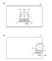
- FIG. 6 is a diagram showing a positional relationship between a front vehicle and a mark image visually recognized by a driver who is seated in a driver's seat of the own vehicle and facing forward, and a display area of a head-up display.
- FIG. 5A shows the positional relationship between the display area where the display range is not reflected in the mark image and the preceding vehicle
- FIG. 5B is the display area where the display range is reflected in the mark image.
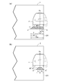
- FIG. 6 is a diagram illustrating a difference between the mark images depending on the presence or absence of the display limitation in the positional relationship between the display area in which the display limitation range can be reflected in the mark image of FIG. 5B and the preceding vehicle.
- FIG. 6A shows a mark image in which the display restriction is not reflected
- FIG. 6B shows a mark image in which the display restriction is reflected. It is the figure quoted in order to demonstrate the display method of the mark image before and behind the front vehicle straddling a display area.
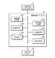
- FIG. 1 shows a configuration diagram of a vehicle display device 1 of the present embodiment.
- the vehicular display device 1 projects a stereo camera 10 (imaging means described later) that images the foreground of the own vehicle 2 and display light L that represents the virtual image V onto the windshield 2a of the own vehicle 2 to create a virtual image.
- a specific object such as a HUD 20 (display means described later) that allows the occupant (user) 3 of the own vehicle 2 to visually recognize V and another vehicle in front of the own vehicle imaged by the stereo camera 10 (hereinafter referred to as a front vehicle).
- the ECU 30 that superimposes the mark image displayed as the virtual image V on the front vehicle in accordance with the movement of the front vehicle while maintaining a predetermined positional relationship with the front vehicle and draws it in the display area and displays it on the HUD 20 ( Electrical Control Unit: a control unit described later).
- the “display area” has two sets of diagonal sizes equal to each other, or two sets of opposite sides having the same length, which are assigned so as to overlap the position of the windshield 2a of the vehicle. It refers to the effective screen area of a virtual image with a rectangular shape. In the display area, the position relative to the windshield 2a viewed from the occupant 3 and the position relative to the foreground through the windshield 2a change depending on the position of the viewpoint of the occupant 3.
- the HUD 20 directs the display light L to the display area of the windshield 2a to make the occupant 3 visually recognize the virtual image V in the display area.
- the ECU 30 can detect the viewpoint position of the occupant 3, and adjusts the position where the virtual image V is visually recognized based on the viewpoint position of the occupant 3. Thereby, the occupant 3 can visually recognize the virtual image V aligned with the front vehicle in the foreground of the own vehicle 2.
- the ECU 30 can analyze the presence or absence of the forward vehicle F (FIG. 5A) by performing image analysis on the imaged data acquired by the stereo camera 10 by, for example, a pattern matching method. Further, for example, the distance (relative positional relationship) between the front vehicle F and the host vehicle 2 can be calculated by image analysis based on the principle of triangulation, and further, the distance between the host vehicle 2 and the front vehicle F can be calculated. It is possible to calculate the relative speed of the front vehicle F with the speed of the host vehicle 2 as a reference by detecting the distance continuously or intermittently and comparing the time difference. It should be noted that the ECU 30 may obtain the relative positional relationship or the relative speed from the mutual vehicle positions and the temporal difference between the vehicle positions by vehicle-vehicle communication or road-vehicle communication via a communication infrastructure on the road.
- the ECU 30 includes a CPU, a graphic controller, a memory, and the like, and as will be described later, recognizes the front vehicle F from the foreground image of the vehicle 2 captured by the stereo camera 10 as the image capturing means, and at least a part of the front vehicle F is detected.
- the width of the front vehicle F in the width direction (first length in FIG. 6A) when straddling the side edge ER (FIG. 5B) in the width direction of the display area E (FIG. 5A).
- A is set as a reference
- a display limit range ⁇ (FIG. 6A) is set for the mark image M (virtual image V) whose length is determined, and a new display limit range ⁇ is reflected.
- a new mark image M′ (virtual image) is generated, the new mark image M′ (virtual image) is superimposed in the vicinity of the front vehicle F (for example, the lower portion), and is drawn in the display area E to be displayed on the HUD 20 as a display unit. Control to display.
- the ECU 30 for example, as shown in FIG. 2, the captured image acquisition unit 301, the image analysis unit 302, the storage unit 303, the display image generation unit 304, the image drawing unit 305, and the display control unit 306. And, it should be noted that the captured image acquisition unit 301, the image analysis unit 302, the display image generation unit 304, the image drawing unit 305, and the display control unit 306 are operated by the CPU configuring the ECU 30 and the graphic controller in cooperation with each other. By this, the respective functions of the respective blocks 301, 302, 304, 305, 306 described below are realized.
- the captured image acquisition unit 301 captures the foreground of the vehicle 2 captured by the stereo camera 10 as an image and outputs it to the image analysis unit 302.
- the image analysis unit 302 analyzes the image acquired by the captured image acquisition unit 301 by a pattern matching method to analyze the presence or absence of the forward vehicle F. Further, the distance (relative positional relationship) between the front vehicle F and the own vehicle 2 is calculated by image analysis based on the principle of triangulation and is output to the display image generation unit 304. Further, the distance between the host vehicle 2 and the preceding vehicle F is continuously or intermittently detected, and the relative speed of the preceding vehicle F is calculated based on the speed of the host vehicle 2 by comparing the time difference and the like, and a display image is displayed. Output to the generation unit 304.
- the display image generation unit 304 determines that the front vehicle F is present in the display area E based on the position information of the front vehicle F output from the image analysis unit 302, for example, FIG. As shown in, a mark image M (virtual image V) that moves following the movement of the front vehicle F (while maintaining a predetermined positional relationship t with the front vehicle F) is generated. On the other hand, for example, as shown in FIG. 5B described later, when it is detected that at least a part of the front vehicle F crosses the side edge ER in the width direction (right) of the display area E, the front vehicle is detected.
- a display limit range ⁇ is set for the mark image M (virtual image V) whose length is determined based on the widthwise length of F, and a new mark image M in which the display limit range ⁇ is reflected. '(FIG. 6B) is generated and output to the image drawing unit 305.
- the length in the width direction of the mark image M (virtual image) before the limited range ⁇ of the display is reflected is the same as the length in the width direction (vehicle width direction) of the front vehicle F, or The length is 110% or 90% of the length in the width direction (vehicle width direction).
- a trapezoid having a first end portion a and a second end portion b, which is longer than the vehicle width of the front vehicle F by about 110%, is long in the width direction.
- a shaped mark image M (virtual image) is generated.
- the display image generation unit 304 for example, as shown in FIG. 6A to be described later, is half the first length ⁇ (first end portion) of the mark image M (virtual image V) drawn in the display area E. a half of the length from a to the second end b (a-c)) and the second length ⁇ from the center position Xc in the width direction of the rear view of the front vehicle F to the side end ER of the display area E.
- a half of the length from a to the second end b (a-c)) and the second length ⁇ from the center position Xc in the width direction of the rear view of the front vehicle F to the side end ER of the display area E By comparing with, it is detected whether the vehicle in front is in the display area or whether the vehicle in front is outside the display area E across the side edge in the width direction.
- the display limit range ⁇ is set to the first end portion a toward the side end of the display region E by the first limit a.
- the length (2 ⁇ ) is set to a value obtained by subtracting twice the length (2 ⁇ ) of the second length, and the mark is set according to the width in the width direction of the rear view of the front vehicle F outside the display area E.
- a new mark image M′ (virtual image V) generated by reducing the length of the image M (virtual image V) is superimposed below the front vehicle F to generate a display image and output it to the image drawing unit 305. To do.
- the display image generation unit 304 offsets a new mark image toward the side edge ER in the width direction of the display area E by the amount ⁇ of the length of the mark image M (virtual image) to which the set display limit is applied.
- Limitation of display by setting the first end portion a′ of M′ (virtual image) and the side edge ER of the display area E in the width direction to the second end portion b′ of the new mark image M′ (virtual image).
- a new mark image M′ (virtual image) in which the range is reflected is generated.
- the new mark image M'(virtual image) is arranged symmetrically with respect to the center position of the front vehicle F (vehicle width center Xc). For example, as shown in FIG.
- a new mark image M′ (virtual image V) having the same dimensions for both LR and the vehicle width center Xc is generated. It should be noted that it is not essential to dispose the new mark image M′ (virtual image) symmetrically with respect to the center position (vehicle width center Xc) of the front vehicle F, and the longer one is reduced with reference to the center position Xc. You may arrange.
- the display image generation unit 304 determines the respective end shapes of the first end portion a′ and the second end portion b′ of the new mark image M′ (virtual image) in which the display limit range ⁇ is reflected. , The first end portion a and the second end portion b of the mark image M (virtual image V) before the limited range ⁇ of display is reflected are generated in the same shape.
- a mark having the same end shape, that is, a trapezoidal shape that is long in the width direction is displayed before and after the display limit range ⁇ is reflected. Images M and M'are generated.
- the image drawing unit 305 superimposes the mark image M (virtual image) or the new mark image M′ (virtual image) generated by the display image generating unit 304 in the vicinity (downward) of the front vehicle F and draws it in the display area E. Take control. Specifically, the image drawing unit 305 displays a display generated by the display image generation unit 304 on a display memory area that is allocated to a partial area of the storage unit 303 and has a storage capacity corresponding to the display area E. Transfer (write) images at high speed. Then, the display control unit 306 reads the display image written in the display memory area of the storage unit 303 in synchronization with the display timing of the HUD 20, and outputs the read image to the HUD 20 to obtain a desired display.
- the storage unit 303 includes a display control program executed by a CPU included in the ECU 30, a captured image of the foreground of the vehicle 2 captured by the stereo camera 10, the above-described display memory, or a display image generation unit 304.
- a work memory or the like in which information in the process of processing including an image before transfer of the mark image M (virtual image) or the like to be transferred to the display memory is allocated and stored, for example, dRAM (dynamic RAM) or static RAM, Alternatively, it is a semiconductor memory in which a flash RAM or the like is mounted.
- FIG. 5 and 7 are operation conceptual diagrams showing the operation of the vehicle display device 1 of the present embodiment on the display area E, and the relationship between the front vehicle F and the mark image M (virtual image) will be described.
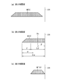
- FIG. 5 a display example of the mark image M (virtual image) when the front vehicle F straddles the display area E (FIG. 6), the mark image M before and after the front vehicle F straddles the display area E ( Virtual images) and M'(virtual images) are shown in each of the figures (FIG. 7) quoted to explain the display method.
- FIGS. 1 and 2 The operation of the vehicle display device 1 of the present embodiment shown in FIGS. 1 and 2 will be described in detail below with reference to FIGS. 5 to 7 and using the flowcharts of FIGS. 3 and 4.
- the captured image acquisition unit 301 of the ECU 30 acquires the foreground image of the own vehicle 2 captured by the stereo camera 10 stored in the storage unit 303. , To the image analysis unit 302 (step ST10). In response to this, the image analysis unit 302 analyzes the acquired image as described below (step S11).
- the image analysis unit 302 analyzes the presence or absence of the forward vehicle F included in the foreground of the host vehicle 2 by performing image analysis by the pattern matching method.
- the image analysis unit 302 further analyzes the front vehicle F and the host vehicle 2 by image analysis based on the principle of triangulation. The distance between them (relative positional relationship) is calculated, and the distance between the host vehicle 2 and the forward vehicle F is continuously or intermittently detected, and the speed of the host vehicle 2 is used as a reference by comparing the time difference.
- the relative speed of the preceding vehicle is calculated and output as the analysis information to the display image generation unit 304 (step ST13).
- the display image generation unit 304 refers to the analysis information output from the image analysis unit 302 and determines whether or not a part of the front vehicle F crosses the display area E (step ST14).
- the display image generation unit 304 will be described later, for example.
- a normal mark image M virtual image V that moves following the movement of the vehicle F in front is generated (step ST16).
- a display limit range is set for the mark image M (virtual image V) whose length is determined with reference to the length of the front vehicle F in the width direction, and the display limit is set.
- a new mark image M′ (FIG. 6B) in which the range is reflected is generated and output to the image drawing unit 305 (step ST15).
- the image drawing unit 305 superimposes the mark image M (virtual image) or the new mark image M′ (virtual image) generated by the display image generating unit 304 in the vicinity of the front vehicle F. Then, control is performed to draw in the display area E (display memory area of the storage unit 303). Then, the display control unit 306 reads the display image written in the display memory area of the storage unit 303 in synchronization with the display timing of the HUD 20, and outputs the read image to the HUD 20 to obtain a desired display (step ST17).
- FIG. 4 shows a detailed operation flow of "display of the mark image M'(V) in which the display limit range is set” in step ST15.
- the display image generation unit 304 first calculates the left and right ends Xs, Xe of the front vehicle from the rear view (or front view) of the front vehicle F by image processing (step ST151). Then, the center position (vehicle width center) of the front vehicle F is calculated (step ST152).
- the vehicle width center can be calculated by simply dividing the coordinates of the left and right ends by 2, or by using the tail lamp, the rear glass, the tire, etc. as a reference.
- the display image generation unit 304 for example, as shown in FIG. 6A, the first end portion a to the second end portion b of the mark image M (virtual image V) drawn in the display area E.
- the first length (horizontal width) up to the second length ⁇ from the center position Xc in the width direction of the rear view of the front vehicle F to the side edge ER of the display area E (step ST153).
- the display limit range ⁇ is set (step ST155).
- the display limit range ⁇ set here is offset from the first end a of the mark image M (virtual image V) drawn in the display area E toward the side edge ER of the display area E by 2 ⁇ . 2 ⁇ (the amount obtained by subtracting twice the length (2 ⁇ ) of the second length from the first length (2 ⁇ )).
- the display image generation unit 304 is newly generated by reducing the length of the mark image M (virtual image V) according to the width direction width of the rear view of the front vehicle F outside the display area E.
- the mark image M′ (virtual image V) is superimposed below the front vehicle F (step ST157).
- the display image generation unit 304 for example, as shown in FIG. 6A, displays the display area E by the amount ⁇ of the length of the mark image M (virtual image) that the set display limit extends.
- the first end portion a′ of the new mark image M′ (virtual image) is offset toward the side edge ER in the width direction, and the side edge ER in the width direction of the display area E is added to the new mark image M′ (virtual image).
- Second end b' a new mark image M'(virtual image) in which the display limit range is reflected is generated. Then, as shown in FIG. 6B, a new mark image M′ (virtual image) is arranged symmetrically with respect to the center position Xc of the front vehicle F.
- the display image generation unit 304 displays the respective shapes of the first end portion a′ and the second end portion b′ of the new mark image M′ (virtual image) in which the limited range of display is reflected. It is generated in the same shape as the respective shapes of the first end portion a and the second end portion b of the mark image before the restriction range is reflected.
- the same end shape (width) is obtained both before (FIG. 7A) and after (FIG. 7C) the display limit range is reflected.
- the mark images M and M′ are generated with a trapezoidal shape that is long in the direction.
- FIG. 7B it is possible to obtain an effect that a mark image can be recognized without a sense of discomfort as compared with a case where the side edge ER of the display area E has a different shape.
- the center position of the vehicle ahead (the center of the vehicle width) is located outside the side edge ER of the display area E, the mark image M (virtual image) is not displayed.
- the case where the front vehicle crosses the side edge ER in the width direction (right) of the display area E is exemplified only, but the limit range ⁇ of the display is set, but the reverse width direction of the display area E is illustrated. Similar control is performed when straddling the (left) side edge.
- the mark images M and M′ are generated as the trapezoidal shape that is long in the width direction has been shown, but it is not essential that the trapezoidal shape is used, and a rectangular shape or a linear shape that is long in the width direction is used. It may be.
- the front vehicle is illustrated as the specific object in front of the vehicle, a motorcycle, a pedestrian, a blind spot, etc. existing in front of the host vehicle 2 are arbitrarily described as the specific object.
- the width of the mark image M (virtual image) to be relatively long (about twice the width of a motorcycle or a pedestrian) as compared with the case of four wheels, so that the display area E is straddled. It is necessary to consider that the mark image M (virtual image) is reduced in size and displayed.
- the normal mark image is displayed when the specific object is in the display area, and when the specific object crosses the display area. Since a new mark image in which the display limit range is reflected is displayed, a part of the mark image to be superimposed is not chipped when a specific object crosses the display area. As a result, it is possible to eliminate the imbalance in the display of the mark image before and after the specific object straddles the display area, and eliminate the appearance discomfort given to the user, which can contribute to safe and comfortable vehicle operation. ..
- the vehicle display device 1 of the present embodiment when the specific object crosses the display area, the mark image of the specific object outside the display area is displayed according to the length in the width direction.
- the mark image By reducing the length and superimposing it as a new mark image below (or above) a specific object, a predetermined positional relationship with the specific object that has captured the new mark image can be obtained. It is possible to display while following the movement of a specific object while maintaining, and when the specific vehicle straddles the display area, the mark image is displayed in a reduced size, so the display limit range is limited. It is possible to eliminate the imbalance in the display of the mark image before and after the reflection, so that the user does not feel uncomfortable in appearance.
- the vehicle display device 1 of the present embodiment by arranging the new mark image in which the limited range of the display is reflected symmetrically with respect to the center position of the specific object, it is possible to further specify the new mark image.
- the unbalance of the display of the mark image before and after the vehicle crossing the display area can be eliminated, and as a result, the user does not feel discomfort in appearance, which contributes to safe and comfortable vehicle operation.
- the vehicle display device 1 of the present embodiment by displaying the same target object while maintaining the same edge shape before and after the specific object straddles the display area, it is possible to obtain different shapes at the side edges of the display area. In comparison with the above case, the user can recognize the image as a mark image without a feeling of strangeness.
- the mark image displayed corresponding to the specific target object on the foreground of the vehicle including the specific target object is displayed as a virtual image in the HUD 20 so as to be highlighted.
- the mark image virtual image
- display control program of the present embodiment display control that eliminates an unbalanced display before and after at least a part of a specific object straddles the display area, and consequently eliminates a feeling of strangeness given to the user. It can be realized by a software program with a simple configuration.
- the present invention relates to a vehicle display device 1 such as a HUD that displays a mark image indicating the position of a specific target object such as a vehicle, a pedestrian, or a blind spot existing in front of the host vehicle in a superimposed manner on the specific target object 1. Can be applied to.
- a vehicle display device 1 such as a HUD that displays a mark image indicating the position of a specific target object such as a vehicle, a pedestrian, or a blind spot existing in front of the host vehicle in a superimposed manner on the specific target object 1. Can be applied to.
- SYMBOLS 1 Vehicle display device, 10... Stereo camera (imaging means), 20... HUD (display means), 30... ECU (control means), 301... Captured image acquisition part, 302 ... image analysis section, 303... storage section, 304... display image generation section, 305... image drawing section, 306... display control section, E... display area, F... Forward vehicle (specific object), M... Mark image (virtual image V), M'... New mark image (virtual image V)
Landscapes
- Engineering & Computer Science (AREA)
- Physics & Mathematics (AREA)
- General Physics & Mathematics (AREA)
- Chemical & Material Sciences (AREA)
- Combustion & Propulsion (AREA)
- Transportation (AREA)
- Mechanical Engineering (AREA)
- Computer Hardware Design (AREA)
- Theoretical Computer Science (AREA)
- Optics & Photonics (AREA)
- Instrument Panels (AREA)
- Traffic Control Systems (AREA)
Abstract
特定の対象物が表示領域を跨ぐ際に、重畳の対象であるマーク画像の一部が欠けることにより生じるマーク画像の表示のアンバランスを解消する。 撮像手段(ステレオカメラ10)が撮像した特定の対象物との間で所定の位置関係を維持しながら特定の対象物の動きに追従して表示されるマーク画像を特定の対象物に重畳し、表示領域に描画して表示手段(HUD20)に表示する制御手段(ECU30)を有し、制御手段は、特定の対象物の少なくとも一部が、表示領域の幅方向の側端を跨った場合に、特定の対象物の幅方向の長さを基準にその長さが決定されるマーク画像に対して表示の制限範囲を設定し、表示の制限範囲が反映された新たなマーク画像を生成し、新たなマーク画像を特定の対象物の近傍に重畳し、表示領域に描画して表示手段に表示する制御を行う。
Description
本発明は、例えば、自動車等の車両に搭載される表示制御装置及びその表示制御プログラムに関する。
ヘッドアップディスプレイ(HUD:Head Up Display)は、車両前方の風景に重畳画像を重ねて表示することで実景に情報等を付加し、強調した拡張現実(AR:Argumented Reality)を生成し、車両を運転するユーザの視線移動を極力抑えつつ、所望の情報を的確に提供することで、安全で快適な車両運行に寄与することができるものである。
ところで、HUDが表示する画像の一つに、車両の前方に存在する他車両、歩行者、死角等、特定の対象物を囲んでその位置を強調するマーク画像が知られている。このマーク画像を用いてユーザに特定の対象物の存在を認識させる技術が、例えば、特許文献1に記載されている。
しかしながら、HUDは表示領域が限られているため、表示領域外にある特定の対象物については強調表示することができない。つまり、表示領域内にあった特定の対象物が表示領域を跨いで外側に外れた場合、マーク画像の一部が欠け、特定の対象物の一部にしか重畳されないため、表示のアンバランスが生じる。従って、ユーザに見た目の違和感を与えることから安全で快適な車両運行に悪影響を与える。
本発明は、上記した課題に着目してなされたものであり、特定の対象物が表示領域を跨ぐ際に、重畳の対象であるマーク画像の一部が欠けることにより生じるマーク画像の表示のアンバランスを解消することでユーザに与える見た目の違和感をなくした、車両用表示装置及びその表示制御プログラムを提供することを目的とする。
本発明の他の目的は、以下に例示する態様及び最良の実施形態、並びに添付の図面を参照することによって、当業者に明らかになるであろう。
以下に、本発明の概要を容易に理解するために、本発明に従う態様を例示する。
第1の態様において、車両用表示制御装置は、
車両の前景にある特定の対象物の位置を示すマーク画像を前記特定の対象物に重畳して表示する制御を行う車両用表示装置であって、
表示領域に画像を表示する表示手段と、
前記車両の前景にある特定の対象物との間で所定の位置関係を維持しながら前記特定の対象物の動きに追従して表示される前記マーク画像を前記特定の対象物に重畳し、前記表示領域に描画して前記表示手段に表示する制御手段と、を有し、
前記制御手段は、
前記特定の対象物の少なくとも一部が、前記表示領域の幅方向の側端を跨った場合に、前記特定の対象物の幅方向の長さを基準にその長さが決定される前記マーク画像に対して表示の制限範囲を設定し、前記表示の制限範囲が反映された新たなマーク画像を生成し、前記新たなマーク画像を前記特定の対象物の近傍に重畳し、前記表示領域に描画して前記表示手段に表示する制御を行う。
車両の前景にある特定の対象物の位置を示すマーク画像を前記特定の対象物に重畳して表示する制御を行う車両用表示装置であって、
表示領域に画像を表示する表示手段と、
前記車両の前景にある特定の対象物との間で所定の位置関係を維持しながら前記特定の対象物の動きに追従して表示される前記マーク画像を前記特定の対象物に重畳し、前記表示領域に描画して前記表示手段に表示する制御手段と、を有し、
前記制御手段は、
前記特定の対象物の少なくとも一部が、前記表示領域の幅方向の側端を跨った場合に、前記特定の対象物の幅方向の長さを基準にその長さが決定される前記マーク画像に対して表示の制限範囲を設定し、前記表示の制限範囲が反映された新たなマーク画像を生成し、前記新たなマーク画像を前記特定の対象物の近傍に重畳し、前記表示領域に描画して前記表示手段に表示する制御を行う。
第1の態様では、制御手段が、特定の対象物の少なくとも一部が表示領域の幅方向の側端を跨った場合に、特定の対象物の幅方向の長さを基準にその長さが決定されるマーク画像に対して表示の制限範囲を設定し、表示の制限範囲が反映された新たなマーク画像を生成し、新たなマーク画像を特定の対象物の近傍に重畳し、表示領域に描画して表示手段に表示する制御を行う。すなわち、特定の対象物が表示領域内にある場合と表示領域を跨る場合とで、表示手段に対して異なるマーク画像を表示することができる。換言すれば、特定の対象物が表示領域内にある場合に通常のマーク画像が表示され、特定の対象物が表示領域を跨った場合に表示の制限範囲が反映された新たなマーク画像が表示される。このため、特定の対象物が表示領域を跨いだ場合に重畳の対象であるマーク画像の一部が欠けることがなくなる。その結果、特定の対象物が表示領域を跨ぐ前後でのマーク画像の表示のアンバランスを解消することができ、その結果、ユーザに与える見た目の違和感がなくなるため、安全で快適な車両運行に寄与することができる。
第1の態様に従属する第2の態様において、
前記制御手段は、
前記表示領域に描画された前記マーク画像の第1の端部から第2の端部までの第1の長さの半分と、前記特定の対象物の幅方向の中心位置から前記表示領域の前記側端までの第2の長さとを比較し、前記第1の長さの半分が前記第2の長さより長くなった場合に、前記第1の端部から前記表示領域の側端に向かい、前記第1の長さから前記第2の長さの2倍の長さを減じた分を前記表示の制限範囲とし、前記表示領域の外側にある前記特定の対象物の幅方向の長さに応じて前記マーク画像の長さを縮小することにより生成される前記新たなマーク画像を前記特定の対象物の下方に重畳し、前記表示領域に描画する制御を行う。
前記制御手段は、
前記表示領域に描画された前記マーク画像の第1の端部から第2の端部までの第1の長さの半分と、前記特定の対象物の幅方向の中心位置から前記表示領域の前記側端までの第2の長さとを比較し、前記第1の長さの半分が前記第2の長さより長くなった場合に、前記第1の端部から前記表示領域の側端に向かい、前記第1の長さから前記第2の長さの2倍の長さを減じた分を前記表示の制限範囲とし、前記表示領域の外側にある前記特定の対象物の幅方向の長さに応じて前記マーク画像の長さを縮小することにより生成される前記新たなマーク画像を前記特定の対象物の下方に重畳し、前記表示領域に描画する制御を行う。
第2の態様では、制御手段が、表示領域に描画されたマーク画像の第1の長さの半分と、特定の対象物の幅方向の中心位置から表示領域の側端までの第2の長さとを比較し、第1の長さの半分が第2の長さより長くなった場合に、表示領域に描画されたマーク画像の第1の端部から表示領域の側端に向かい、第1の長さから第2の長さの2倍の長さを減じた分を表示の制限範囲とし、表示領域の外側にある特定の対象物の幅方向の長さに応じてマーク画像の長さを縮小することにより生成される新たなマーク画像を特定の対象物の下方に重畳し、表示領域に描画する制御を行う。従って、第2の態様によれば、特定の対象物が表示領域を跨った場合に、表示領域の外側にある特定の対象物の幅方向の長さに応じてマーク画像の長さを縮小し、新たなマーク画像として特定の対象物の下方に重畳することで、新たなマーク画像を撮像した特定の対象物との間で所定の位置関係を維持しながら特定の対象物の動きに追従して表示することができる。また、特定の車両が表示領域を跨いた場合に、マーク画像が縮小して表示されることから、表示の制限範囲が反映される前後でのマーク画像の表示のアンバランスを解消でき、ユーザに与える見た目の違和感がなくなる。
第1又は第2の態様に従属する第3の態様において、
前記制御手段は、
設定された前記表示の制限が及ぶ前記マーク画像の長さの分だけ前記表示領域の幅方向の側端に向かってオフセットして前記新たなマーク画像の第1の端部とし、前記表示領域の幅方向の側端を前記新たなマーク画像の第2の端部とすることにより前記表示の制限範囲が反映された新たなマーク画像を生成し、前記新たなマーク画像を前記特定の対象物の中心位置を基準に左右対称に配置する。
前記制御手段は、
設定された前記表示の制限が及ぶ前記マーク画像の長さの分だけ前記表示領域の幅方向の側端に向かってオフセットして前記新たなマーク画像の第1の端部とし、前記表示領域の幅方向の側端を前記新たなマーク画像の第2の端部とすることにより前記表示の制限範囲が反映された新たなマーク画像を生成し、前記新たなマーク画像を前記特定の対象物の中心位置を基準に左右対称に配置する。
第3の態様では、制御手段が、設定された表示の制限範囲が及ぶマーク画像の長さの分だけ表示領域の幅方向の側端に向かってオフセットして新たなマーク画像の第1の端部とし、表示領域の幅方向の側端を新たなマーク画像の第2の端部とすることにより表示の制限範囲が反映された新たなマーク画像を生成し、新たなマーク画像を特定の対象物の中心位置を基準に左右対称に配置する。従って、第3の態様によれば、表示の制限範囲が反映された新たなマーク画像を特定の対象物の中心位置を基準に左右対称に配置することで、より一層、特定の車両が表示領域を跨ぐ前後での表示のアンバランスを解消することができ、結果的にユーザに与える見た目の違和感がなくなることから安全で快適な車両運行に寄与することができる。
第1乃至第3の態様に従属する第4の態様において、
前記制御手段は、
前記表示の制限範囲が反映された前記新たなマーク画像の第1の端部と第2の端部のそれぞれの形状を、前記表示の制限範囲が反映される前の前記マーク画像の第1の端部と第2の端部のそれぞれの形状と同じ形状で前記表示領域に描画する制御を行う。
前記制御手段は、
前記表示の制限範囲が反映された前記新たなマーク画像の第1の端部と第2の端部のそれぞれの形状を、前記表示の制限範囲が反映される前の前記マーク画像の第1の端部と第2の端部のそれぞれの形状と同じ形状で前記表示領域に描画する制御を行う。
第4の態様では、制御手段が、新たなマーク画像の第1の端部と第2の端部のそれぞれの形状を、表示の制限範囲が反映される前のマーク画像の第1の端部と第2の端部のそれぞれの形状と同じ形状で表示領域に描画する制御を行う。換言すれば、制御手段は、特定の対象物が表示領域を跨ぐ前後のいずれにおいても同じ端形状を維持して表示手段に表示する。このため、第4の態様によれば、特定の対象物が表示領域を跨ぐ前後で端形状が変わる場合に比べてユーザにマーク画像として違和感なく認識させることができる。
第1乃至第4の態様に従属する第5の態様において、
前記表示手段は、
前記マーク画像を虚像で表示するヘッドアップディスプレイである。
前記表示手段は、
前記マーク画像を虚像で表示するヘッドアップディスプレイである。
第5の態様では、ヘッドアップディスプレイに、特定の対象物を含む車両の前景に特定の対象物に対応して表示されるマーク画像が虚像で重畳されて強調表示される。このため、第5の態様によれば、マーク画像(虚像)によって自車両の前方に存在する他車両、歩行者、あるいは死角等、特定の対象物を強調することができ、車両を運転するユーザの視線移動を極力抑えつつ所望の情報(特定の対象物の位置)を的確に提供することができる。従って、安全で快適な車両運行に寄与することができる。
第6の態様において、表示制御プログラムは、
コンピュータを、第1乃至第5の何れか1つの態様の車両用表示装置として動作させる。
コンピュータを、第1乃至第5の何れか1つの態様の車両用表示装置として動作させる。
第7の態様によれば、特定の対象物の少なくとも一部が表示領域を跨ぐ前後での表示のアンバランスを解消し、結果的にユーザに与える見た目の違和感を解消する表示制御をソフトウエアプログラムにより簡単な構成で実現することができる。
本発明によれば、特定の対象物が表示領域を跨ぐ際に、重畳の対象であるマーク画像の一部が欠けることにより生じる表示のアンバランスを解消することでユーザに与える見た目の違和感を無くした、車両用表示装置及びその表示制御プログラムを提供することができる。
当業者は、例示した本発明に従う態様が、本発明の精神を逸脱することなく、さらに変更され得ることを容易に理解できるであろう。
以下に説明する最良の実施形態は、本発明を容易に理解するために用いられている。従って、当業者は、本発明が、以下に説明される実施形態によって不当に限定されないことを留意すべきである。
(実施形態の構成)
図1に本実施形態の車両用表示装置1の構成図を示す。本実施形態の車両用表示装置1は、自車両2の前景を撮像するステレオカメラ10(後述する撮像手段)と、虚像Vを表す表示光Lを自車両2のフロントガラス2aに投影し、虚像Vを自車両2の乗員(ユーザ)3に視認させるHUD20(後述する表示手段)と、ステレオカメラ10により撮像される自車両の前方の他車両等の特定の対象物(以下、前方車両という)との間で所定の位置関係を維持しながら前方車両の動きに追従(同期)して虚像Vとして表示されるマーク画像を前方車両に重畳し、表示領域に描画してHUD20に表示するECU30(Electrical Control Unit:後述する制御手段)と、から構成される。
図1に本実施形態の車両用表示装置1の構成図を示す。本実施形態の車両用表示装置1は、自車両2の前景を撮像するステレオカメラ10(後述する撮像手段)と、虚像Vを表す表示光Lを自車両2のフロントガラス2aに投影し、虚像Vを自車両2の乗員(ユーザ)3に視認させるHUD20(後述する表示手段)と、ステレオカメラ10により撮像される自車両の前方の他車両等の特定の対象物(以下、前方車両という)との間で所定の位置関係を維持しながら前方車両の動きに追従(同期)して虚像Vとして表示されるマーク画像を前方車両に重畳し、表示領域に描画してHUD20に表示するECU30(Electrical Control Unit:後述する制御手段)と、から構成される。
なお、「表示領域」とは、自車両のフロントガラス2aの位置と重複するように割り当てられた、2組の対角の大きさがそれぞれ等しいか、あるいは2組の対辺の長さがそれぞれ等しい矩形形状からなる虚像の有効画面範囲のことをいう。なお、表示領域は、乗員3の視点の位置により、乗員3から見たフロントガラス2aとの相対的な位置、及びフロントガラス2aを介した前景との相対的な位置が変化する。
HUD20は、ECU30による制御の下、フロントガラス2aの表示領域に表示光Lを向けることで、表示領域内に虚像Vを乗員3に視認させる。なお、ECU30は、乗員3の視点位置を検出することができ、乗員3の視点位置に基づいて、虚像Vが視認される位置を調整する。これにより、乗員3は、自車両2の前景における前方車両に位置合わせされた虚像Vを視認することができる。
ECU30は、ステレオカメラ10で取得された撮像データを、例えば、パターンマッチング法により画像解析することで、前方車両F(図5(a))の有無を解析することができる。また、例えば、三角測量の原理に基づく画像解析により前方車両Fと自車両2との間の距離(相対的な位置関係)を算出することができ、更に、自車両2と前方車両Fとの距離を連続的または断続的に検出し、その時間差分などの比較により自車両2の速度を基準とした前方車両Fの相対速度を算出することができる。なお、ECU30は、車車間通信や路上の通信インフラを介した路車間通信等により、互いの車両位置とその時間的差分によって相対的な位置関係や相対速度を求めてもよい。
ECU30は、CPU,グラフィックコントローラ,メモリなどを含み、後述するように、撮像手段としてのステレオカメラ10が撮像した自車両2の前景画像から前方車両Fを認識し、前方車両Fの少なくとも一部が表示領域E(図5(a))の幅方向の側端ER(図5(b))を跨った場合に、前方車両Fの幅方向の長さ(図6(a)の第1の長さα)を基準にその長さが決定されるマーク画像M(虚像V)に対して表示の制限範囲γ(図6(a))を設定し、その表示の制限範囲γが反映された新たなマーク画像M’(虚像)を生成し、この新たなマーク画像M’(虚像)を前方車両Fの近傍(例えば、下部)に重畳し、表示領域Eに描画して表示手段としてのHUD20に表示する制御を行う。
このため、ECU30は、例えば、図2に示すように、撮像画像取得部301と、画像解析部302と、記憶部303と、表示画像生成部304と、画像描画部305と、表示制御部306と、により構成される。なお、撮像画像取得部301と、画像解析部302と、表示画像生成部304と、画像描画部305と、表示制御部306は、ECU30を構成するCPUとグラフックコントローラが協働して動作することにより、以下に説明するそれぞれのブロック301,302,304,305,306が有するそれぞれの機能を実現するものである。
撮像画像取得部301は、ステレオカメラ10により撮像される自車両2の前景を画像として取り込んで画像解析部302へ出力する。
画像解析部302は、撮像画像取得部301により取得された画像を、パターンマッチング法により画像解析することで、前方車両Fの有無を解析する。また、三角測量の原理に基づく画像解析により前方車両Fと自車両2との間の距離(相対的な位置関係)を算出して、表示画像生成部304へ出力する。また、自車両2と前方車両Fとの距離を連続的または断続的に検出し、その時間差分などの比較により自車両2の速度を基準とした前方車両Fの相対速度を算出して表示画像生成部304へ出力する。
表示画像生成部304は、画像解析部302から出力される前方車両Fの位置情報等に基づき、前方車両Fが表示領域E内に存在すると判定された場合、例えば、後述する図5(a)に示すように、前方車両Fの動きに追従(前方車両Fとの間で所定の位置関係tを維持しながら)して動くマーク画像M(虚像V)を生成する。一方、例えば、後述する図5(b)に示すように、前方車両Fの少なくとも一部が表示領域Eの幅方向(右)の側端ERを跨ったことが検出された場合に、前方車両Fの幅方向の長さを基準にその長さが決定されるマーク画像M(虚像V)に対して表示の制限範囲γを設定し、表示の制限範囲γが反映された新たなマーク画像M’(図6(b))を生成して、画像描画部305へ出力する。
なお、表示の制限範囲γが反映される前のマーク画像M(虚像)の幅方向の長さは、前方車両Fの幅方向(車幅方向)の長さと同じか、あるいは、前方車両Fの幅方向(車幅方向)の長さの110%,あるいは90%の長さで生成される。本実施形態では、後述する図5(a)に示すように、前方車両Fの車幅より110%ほど長い、第1の端部aと第2の端部bとを有する幅方向に長い台形形状のマーク画像M(虚像)が生成される。
表示画像生成部304は、例えば、後述する図6(a)に示すように、表示領域Eに描画されたマーク画像M(虚像V)の第1の長さの半分α(第1の端部aから第2の端部bまでの長さの半分(a-c))と、前方車両Fのリアビューの幅方向の中心位置Xcから表示領域Eの側端ERまでの第2の長さβとを比較することにより、前方車両が表示領域内にあるか、あるいは表示領域Eの幅方向の側端を跨って外側に出たかを検出する。そして、第1の長さの半分αが第2の長さβより長くなった場合に、表示の制限範囲γを、第1の端部aから表示領域Eの側端に向かって第1の長さ(2α)から第2の長さの2倍の長さ(2β)を減じた分に設定し、表示領域Eの外側にある前方車両Fのリアビューの幅方向の長さに応じてマーク画像M(虚像V)の長さを縮小することにより生成される新たなマーク画像M’(虚像V)を前方車両Fの下方に重畳することにより表示画像を生成して画像描画部305へ出力する。
表示画像生成部304は、例えば、設定された表示の制限が及ぶマーク画像M(虚像)の長さの分γだけ表示領域Eの幅方向の側端ERに向かってオフセットして新たなマーク画像M’(虚像)の第1の端部a’とし、表示領域Eの幅方向の側端ERを新たなマーク画像M’(虚像)の第2の端部b’とすることにより表示の制限範囲が反映された新たなマーク画像M’(虚像)を生成する。そして、新たなマーク画像M’(虚像)を前方車両Fの中心位置(車幅中心Xc)を基準に左右対称に配置する。例えば、図6(b)に示すように、車幅中心Xcを基準にLR共に同じ寸法を有する新たなマーク画像M’(虚像V)を生成する。なお、新たなマーク画像M’(虚像)を前方車両Fの中心位置(車幅中心Xc)を基準に左右対称に配置することは必須でなく、中心位置Xcを基準に長い方を縮小して配置してもよい。
このとき、表示画像生成部304は、表示の制限範囲γが反映された新たなマーク画像M’(虚像)の第1の端部a’と第2の端部b’のそれぞれの端形状を、表示の制限範囲γが反映される前のマーク画像M(虚像V)の第1の端部aと第2の端部bのそれぞれの形状と同じ形状で生成する。本実施形態では、例えば、図7(a)(c)に示すように、表示の制限範囲γが反映される前後のいずれにおいても、同じ端形状で、すなわち、幅方向に長い台形形状でマーク画像M,M’が生成される。
画像描画部305は、表示画像生成部304によって生成されるマーク画像M(虚像)又は新たなマーク画像M’(虚像)を前方車両Fの近傍(下方)に重畳し、表示領域Eに描画する制御を行う。具体的に、画像描画部305は、記憶部303の一部領域に割り当てられた、表示領域Eに相当する分の記憶容量を有する表示メモリ領域に対して表示画像生成部304により生成される表示画像を高速で転送(書き込む)する。そして、表示制御部306が、記憶部303の表示メモリ領域に書き込まれた表示画像をHUD20の表示タイミングに同期して読み出し、HUD20に出力することにより、所望の表示を得る。
記憶部303は、ECU30を構成するCPUが実行する表示制御プログラムの他に、ステレオカメラ10により撮像される自車両2の前景の撮像画像、上述した表示メモリ、あるいは、表示画像生成部304により生成されるマーク画像M(虚像)等を表示メモリへ転送する前の画像を含む処理途中の情報が記憶される作業メモリ等が割り当てられ、記憶される、例えば、dRAM(ダイナミックRAM)やスタティックRAM、あるいはフラッシュRAM等が実装された半導体メモリである。
(実施形態の動作)
図3,図4は、本実施形態の車両用表示装置1の動作を示すフローチャートであり、基本動作、詳細動作(図3のステップST15)のそれぞれを示す。また、図5~図7は、本実施形態の車両用表示装置1の動作を表示領域E上に示した動作概念図であり、前方車両Fとマーク画像M(虚像)との関係を説明するために引用した図(図5)、前方車両Fが表示領域Eを跨ぐ場合のマーク画像M(虚像)の表示例(図6)、前方車両Fが表示領域Eを跨ぐ前後のマーク画像M(虚像),M’(虚像)の表示の仕方を説明するために引用した図(図7)のそれぞれを示す。
図3,図4は、本実施形態の車両用表示装置1の動作を示すフローチャートであり、基本動作、詳細動作(図3のステップST15)のそれぞれを示す。また、図5~図7は、本実施形態の車両用表示装置1の動作を表示領域E上に示した動作概念図であり、前方車両Fとマーク画像M(虚像)との関係を説明するために引用した図(図5)、前方車両Fが表示領域Eを跨ぐ場合のマーク画像M(虚像)の表示例(図6)、前方車両Fが表示領域Eを跨ぐ前後のマーク画像M(虚像),M’(虚像)の表示の仕方を説明するために引用した図(図7)のそれぞれを示す。
以下、図5~図7を参照しながら、図3,図4のフローチャートを用いて図1,図2に示す本実施形態の車両用表示装置1の動作について詳細に説明する。
図3において、本実施形態の車両用表示装置1は、まず、ECU30の撮像画像取得部301が、記憶部303に記憶されたステレオカメラ10により撮像された自車両2の前景の画像を取得し、画像解析部302へ出力する(ステップST10)。これを受けて画像解析部302は、取得した画像を以下に説明するように解析する(ステップS11)。
画像解析部302は、パターンマッチング法により画像解析することで、自車両2の前景に含まれる前方車両Fの有無を解析する。画像解析部302は、自車両2の前方に「前方車両あり」と判定されると(ステップST12“YES”)、更に、三角測量の原理に基づく画像解析により前方車両Fと自車両2との間の距離(相対的な位置関係)を算出し、また、自車両2と前方車両Fとの距離を連続的または断続的に検出し、その時間差分などの比較により自車両2の速度を基準とした前方車両の相対速度を算出し、解析情報としてそれぞれ表示画像生成部304へ出力する(ステップST13)。
次に、表示画像生成部304は、画像解析部302から出力される解析情報を参照して前方車両Fの一部が表示領域Eを跨るか否かを判定する(ステップST14)。表示画像生成部304は、画像解析部302から出力される前方車両の位置情報等に基づき、前方車両が表示領域E内に存在すると判定された場合(ステップST14“NO”)、例えば、後述する図5(a)に示すように、前方車両Fの動きに追従して動く通常のマーク画像M(虚像V)を生成する(ステップST16)。
一方、例えば、後述する図5(b)に示すように、前方車両Fの少なくとも一部が表示領域Eの幅方向の側端ERを跨ったことが検出された場合に(ステップST14“YES”)、詳細が後述されるように、前方車両Fの幅方向の長さを基準にその長さが決定されるマーク画像M(虚像V)に対して表示の制限範囲を設定し、表示の制限範囲が反映された新たなマーク画像M’(図6(b))を生成して、画像描画部305へ出力する(ステップST15)。
上述したステップST15,ST16の処理の後、画像描画部305は、表示画像生成部304によって生成されるマーク画像M(虚像)又は新たなマーク画像M’(虚像)を前方車両Fの近傍に重畳し、表示領域E(記憶部303の表示メモリ領域)に描画する制御を行う。そして、表示制御部306が、記憶部303の表示メモリ領域に書き込まれた表示画像をHUD20の表示タイミングに同期して読み出し、HUD20に出力して所望の表示を得る(ステップST17)。
ステップST15の「表示の制限範囲が設定されたマーク画像M’(V)の表示」の詳細な動作の流れを図4に示す。図4において、表示画像生成部304は、まず、前方車両Fのリアビュー(あるいはフロントビュー)から前方車両の左右端Xs,Xeを画像処理によって算出し(ステップST151)。続いて、前方車両Fの中心位置(車幅中心)を算出する(ステップST152)。なお、車幅中心の算出は、左右端の座標を単純に2で除算するか、テールランプ、リアガラス、タイヤ等を基準にしても求めることができる。
次に、表示画像生成部304は、例えば、図6(a)に示すように、表示領域Eに描画されたマーク画像M(虚像V)の第1の端部aから第2の端部bまでの第1の長さ(横幅)の半分αと、前方車両Fのリアビューの幅方向の中心位置Xcから表示領域Eの側端ERまでの第2の長さβとを比較する(ステップST153)。比較の結果、前方車両Fが表示領域E内にあるか、あるいは表示領域Eの幅方向の側端ERを跨って外側に出たかを検出する。そして、第1の長さの半分αが第2の長さβより長くなった場合に(ステップST154“YES”)、表示の制限範囲γを設定する(ステップST155)。ここで設定される表示の制限範囲γは、表示領域Eに描画されたマーク画像M(虚像V)の第1の端部aから表示領域Eの側端ERに向かってオフセットされる、2α-2β(第1の長さ(2α)から第2の長さの2倍の長さ(2β)を減じた分)とする。
続いて、表示画像生成部304は、表示領域Eの外側にある前方車両Fのリアビューの幅方向の長さに応じてマーク画像M(虚像V)の長さを縮小することにより生成される新たなマーク画像M’(虚像V)を前方車両Fの下方に重畳する(ステップST157)。ステップST157の処理において、表示画像生成部304は、例えば、図6(a)に示すように、設定された表示の制限が及ぶマーク画像M(虚像)の長さの分γだけ表示領域Eの幅方向の側端ERに向かってオフセットして新たなマーク画像M’(虚像)の第1の端部a’とし、表示領域Eの幅方向の側端ERを新たなマーク画像M’(虚像)の第2の端部b’とすることにより表示の制限範囲が反映された新たなマーク画像M’(虚像)を生成する。そして、図6(b)に示すように、新たなマーク画像M’(虚像)を前方車両Fの中心位置Xcを基準に左右対称に配置する。
このとき、表示画像生成部304は、表示の制限範囲が反映された新たなマーク画像M’(虚像)の第1の端部a’と第2の端部b’のそれぞれの形状を、表示の制限範囲が反映される以前のマーク画像の第1の端部aと第2の端部bのそれぞれの形状と同じ形状で生成する。本実施形態では、例えば、図7に示すように、表示の制限範囲が反映される前(図7(a))と、後(図7(c))のいずれにおいても、同じ端形状(幅方向に長い台形形状)でマーク画像M,M’が生成される。図7(b)に示すように、表示領域Eの側端ERで異なる形状となる場合に比べて違和感なくマーク画像として認識できるという効果が得られる。
なお、前方車両の中心位置(車幅中心)が、表示領域Eの側端ERを跨って外側に位置する場合は、マーク画像M(虚像)は、表示されない。また、本実施形態では、前方車両が表示領域Eの幅方向(右)の側端ERを跨る場合に表示の制限範囲γを設定する場合についてのみ例示したが、表示領域Eの逆の幅方向(左)の側端を跨る場合も同様の制御が行なわれる。また、本実施形態では、マーク画像M,M’を幅方向に長い台形形状として生成する例のみ示したが、台形形状とすることは必須ではなく、幅方向に長い矩形形状、あるいは線形状であってもよい。また、車両の前方にある特定の対象物として、前方車両についてのみ例示したが、自車両2の前方に存在するバイク、歩行者、死角等も特定の対象物として任意記される。但し、バイクや歩行者の場合は、四輪に比べてマーク画像M(虚像)の幅を比較的長く(バイクや歩行者の2倍程度の幅)設定する必要があり、表示領域Eを跨ったときにそのマーク画像M(虚像)を縮小して表示する配慮が必要である。
(実施形態の効果)
以上説明のように本実施形態の車両用表示装置1によれば、特定の対象物が表示領域内にある場合に通常のマーク画像が表示され、特定の対象物が表示領域を跨った場合に表示の制限範囲が反映された新たなマーク画像が表示されるため、特定の対象物が表示領域を跨いだ場合に重畳の対象であるマーク画像の一部が欠けることがなくなる。その結果、特定の対象物が表示領域を跨ぐ前後におけるマーク画像の表示のアンバランスを解消することができ、ユーザに与える見た目の違和感がなくなるため、安全で快適な車両運行に寄与することができる。
以上説明のように本実施形態の車両用表示装置1によれば、特定の対象物が表示領域内にある場合に通常のマーク画像が表示され、特定の対象物が表示領域を跨った場合に表示の制限範囲が反映された新たなマーク画像が表示されるため、特定の対象物が表示領域を跨いだ場合に重畳の対象であるマーク画像の一部が欠けることがなくなる。その結果、特定の対象物が表示領域を跨ぐ前後におけるマーク画像の表示のアンバランスを解消することができ、ユーザに与える見た目の違和感がなくなるため、安全で快適な車両運行に寄与することができる。
また、本実施形態の車両用表示装置1によれば、特定の対象物が表示領域を跨った場合に、表示領域の外側にある特定の対象物の幅方向の長さに応じてマーク画像の長さを縮小し、新たなマーク画像として特定の対象物の下方(あるいは上方)に重畳して表示することで、新たなマーク画像を撮像した特定の対象物との間で所定の位置関係を維持しながら特定の対象物の動きに追従して表示することができ、また、特定の車両が表示領域を跨いた場合に、マーク画像が縮小して表示されることから、表示の制限範囲が反映される前後でのマーク画像の表示のアンバランスを解消でき、ユーザに与える見た目の違和感がなくなる。
また、本実施形態の車両用表示装置1によれば、表示の制限範囲が反映された新たなマーク画像を特定の対象物の中心位置を基準に左右対称に配置することで、より一層、特定の車両が表示領域を跨ぐ前後でのマーク画像の表示のアンバランスを解消でき、結果的にユーザに与える見た目の違和感がなくなることから安全で快適な車両運行に寄与することができる。
また、本実施形態の車両用表示装置1によれば、特定の対象物が表示領域を跨ぐ前後のいずれにおいても同じ端形状を維持して表示することで、表示領域の側端で異なる形状となる場合に比べてユーザにマーク画像として違和感なく認識させることができる。
また、本実施形態の車両用表示装置1によれば、HUD20に、特定の対象物を含む車両の前景に特定の対象物に対応して表示されるマーク画像が虚像で重畳されて強調表示されることで、マーク画像(虚像)によって自車両の前方に存在する他車両、歩行者、あるいは死角等、特定の対象物を強調することができ、車両を運転するユーザの視線移動を極力抑えつつ所望の情報(特定の対象物の位置)を的確に提供することができる。従って、安全で快適な車両運行に寄与することができる。
本実施形態の表示制御プログラムによれば、特定の対象物の少なくとも一部が表示領域を跨ぐ前後での表示のアンバランスを解消し、結果的にユーザに与える見た目の違和感を解消する表示制御をソフトウエアプログラムにより簡単な構成で実現することができる。
本発明は、上述した例示的な実施形態に限定されず、また、当業者は、上述の例示的な実施形態を特許請求の範囲に含まれる範囲まで、容易に変更することができるであろう。
本発明は、自車両の前方に存在する車両、歩行者、死角等、特定の対象物の位置を示すマーク画像をその特定の対象物に重畳して表示する、HUD等の車両用表示装置1に適用可能である。
1・・・車両用表示装置、10・・・ステレオカメラ(撮像手段)、20・・・HUD(表示手段)、30・・・ECU(制御手段)、301・・・撮像画像取得部、302・・・画像解析部、303・・・記憶部、304・・・表示画像生成部、305・・・画像描画部、306・・・表示制御部、E・・・表示領域、F・・・前方車両(特定の対象物)、M・・・マーク画像(虚像V)、M’・・・新たなマーク画像(虚像V)
Claims (6)
- 車両の前景にある特定の対象物の位置を示すマーク画像を前記特定の対象物に重畳して表示する制御を行う車両用表示装置であって、
表示領域に画像を表示する表示手段と、
前記車両の前景にある特定の対象物との間で所定の位置関係を維持しながら前記特定の対象物の動きに追従して表示される前記マーク画像を前記特定の対象物に重畳し、前記表示領域に描画して前記表示手段に表示する制御手段と、を有し、
前記制御手段は、
前記特定の対象物の少なくとも一部が、前記表示領域の幅方向の側端を跨った場合に、前記特定の対象物の幅方向の長さを基準にその長さが決定される前記マーク画像に対して表示の制限範囲を設定し、前記表示の制限範囲が反映された新たなマーク画像を生成し、前記新たなマーク画像を前記特定の対象物の近傍に重畳し、前記表示領域に描画して前記表示手段に表示する制御を行うことを特徴とする車両用表示装置。 - 前記制御手段は、
前記表示領域に描画された前記マーク画像の第1の端部から第2の端部までの第1の長さの半分と、前記特定の対象物の幅方向の中心位置から前記表示領域の前記側端までの第2の長さとを比較し、前記第1の長さの半分が前記第2の長さより長くなった場合に、前記第1の端部から前記表示領域の側端に向かい、前記第1の長さのから前記第2の長さの2倍の長さを減じた分を前記表示の制限範囲とし、前記表示領域の外側にある前記特定の対象物の幅方向の長さに応じて前記マーク画像の長さを縮小することにより生成される前記新たなマーク画像を前記特定の対象物の下方に重畳し、前記表示領域に描画する制御を行うことを特徴とする請求項1に記載の車両用表示装置。 - 前記制御手段は、
設定された前記表示の制限が及ぶマーク画像の長さの分だけ前記表示領域の幅方向の側端に向かってオフセットして前記新たなマーク画像の第1の端部とし、前記表示領域の幅方向の側端を前記新たなマーク画像の第2の端部とすることにより前記表示の制限範囲が反映された新たなマーク画像を生成し、前記新たなマーク画像を前記特定の対象物の中心位置を基準に左右対称に配置することを特徴とする請求項1又は2に記載の車両用表示装置。 - 前記制御手段は、
前記表示の制限範囲が反映された前記新たなマーク画像の第1の端部と第2の端部のそれぞれの形状を、前記表示の制限範囲が反映される前の前記マーク画像の第1の端部と第2の端部のそれぞれの形状と同じ形状で前記表示領域に描画する制御を行うことを特徴とする請求項1~3のいずれか1項に記載の車両用表示装置。 - 前記表示手段は、
前記マーク画像を虚像で表示するヘッドアップディスプレイであることを特徴とする請求項1~4のいずれか1項に記載の車両用表示装置。 - コンピュータを、請求項1~5のいずれか1項に記載の車両用表示装置として動作させることを特徴とする表示制御プログラム。
Applications Claiming Priority (2)
| Application Number | Priority Date | Filing Date | Title |
|---|---|---|---|
| JP2019027112 | 2019-02-19 | ||
| JP2019-027112 | 2019-02-19 |
Publications (1)
| Publication Number | Publication Date |
|---|---|
| WO2020171042A1 true WO2020171042A1 (ja) | 2020-08-27 |
Family
ID=72144634
Family Applications (1)
| Application Number | Title | Priority Date | Filing Date |
|---|---|---|---|
| PCT/JP2020/006182 Ceased WO2020171042A1 (ja) | 2019-02-19 | 2020-02-18 | 車両用表示装置及びその表示制御プログラム |
Country Status (1)
| Country | Link |
|---|---|
| WO (1) | WO2020171042A1 (ja) |
Citations (4)
| Publication number | Priority date | Publication date | Assignee | Title |
|---|---|---|---|---|
| US20140341434A1 (en) * | 2013-05-17 | 2014-11-20 | Industrial Technology Research Institute | Dymanic fusion method and device of images |
| WO2017046937A1 (ja) * | 2015-09-18 | 2017-03-23 | 日産自動車株式会社 | 車両用表示装置及び車両用表示方法 |
| WO2017056157A1 (ja) * | 2015-09-28 | 2017-04-06 | 日産自動車株式会社 | 車両用表示装置及び車両用表示方法 |
| JP2018103697A (ja) * | 2016-12-26 | 2018-07-05 | 日本精機株式会社 | 車両用表示装置 |
-
2020
- 2020-02-18 WO PCT/JP2020/006182 patent/WO2020171042A1/ja not_active Ceased
Patent Citations (4)
| Publication number | Priority date | Publication date | Assignee | Title |
|---|---|---|---|---|
| US20140341434A1 (en) * | 2013-05-17 | 2014-11-20 | Industrial Technology Research Institute | Dymanic fusion method and device of images |
| WO2017046937A1 (ja) * | 2015-09-18 | 2017-03-23 | 日産自動車株式会社 | 車両用表示装置及び車両用表示方法 |
| WO2017056157A1 (ja) * | 2015-09-28 | 2017-04-06 | 日産自動車株式会社 | 車両用表示装置及び車両用表示方法 |
| JP2018103697A (ja) * | 2016-12-26 | 2018-07-05 | 日本精機株式会社 | 車両用表示装置 |
Similar Documents
| Publication | Publication Date | Title |
|---|---|---|
| CA2999961C (en) | Vehicular display device and vehicular display method | |
| JP7523196B2 (ja) | 周辺画像表示装置 | |
| JP5369465B2 (ja) | 車両用画像処理装置、車両用画像処理方法、車両用画像処理プログラム | |
| JP7365594B2 (ja) | 表示システム | |
| JP6958163B2 (ja) | 表示制御装置 | |
| CN108352053A (zh) | 用于环绕监视系统的图像合成器 | |
| JP2020120327A (ja) | 周辺表示制御装置 | |
| CN104735403B (zh) | 车用障碍物侦测显示系统 | |
| JP2017033402A (ja) | 車載表示制御装置、車載表示制御方法 | |
| WO2018159019A1 (ja) | 俯瞰映像生成装置、俯瞰映像生成システム、俯瞰映像生成方法およびプログラム | |
| JP2019083385A (ja) | ヘッドアップディスプレイ装置 | |
| JP2019148935A (ja) | 表示制御装置及びヘッドアップディスプレイ装置 | |
| WO2014006793A1 (ja) | 車両周囲画像表示制御装置、車両周囲画像表示制御方法、当該方法を含む命令からなる持続的有形コンピュータ読み取り媒体 | |
| JP2012138876A (ja) | 画像生成装置、画像表示システム及び画像表示方法 | |
| JP2019054439A (ja) | 画像処理装置 | |
| JP7697539B2 (ja) | 表示制御方法、表示制御装置 | |
| JP7223283B2 (ja) | 画像処理ユニット及びそれを備えるヘッドアップディスプレイ装置 | |
| JP6759132B2 (ja) | ヘッドアップディスプレイ装置及び表示制御方法 | |
| JP2018019155A (ja) | 車両用表示制御装置、車両用表示システム、車両用表示制御方法およびプログラム | |
| JP7816050B2 (ja) | 表示制御装置、表示制御方法及びプログラム | |
| JP6136748B2 (ja) | 2次元3次元表示装置 | |
| JP2018142882A (ja) | 俯瞰映像生成装置、俯瞰映像生成システム、俯瞰映像生成方法およびプログラム | |
| JP7066271B2 (ja) | 画像処理装置、画像処理方法及びヘッドアップディスプレイシステム | |
| JP2020019369A (ja) | 車両用表示装置、方法、及びコンピュータ・プログラム | |
| JP2006279511A (ja) | 周辺監視システム |
Legal Events
| Date | Code | Title | Description |
|---|---|---|---|
| 121 | Ep: the epo has been informed by wipo that ep was designated in this application |
Ref document number: 20759023 Country of ref document: EP Kind code of ref document: A1 |
|
| NENP | Non-entry into the national phase |
Ref country code: DE |
|
| 122 | Ep: pct application non-entry in european phase |
Ref document number: 20759023 Country of ref document: EP Kind code of ref document: A1 |
|
| NENP | Non-entry into the national phase |
Ref country code: JP |