WO2020170953A1 - 軸受部品とそれに付着する異物を除去する方法と装置 - Google Patents
軸受部品とそれに付着する異物を除去する方法と装置 Download PDFInfo
- Publication number
- WO2020170953A1 WO2020170953A1 PCT/JP2020/005702 JP2020005702W WO2020170953A1 WO 2020170953 A1 WO2020170953 A1 WO 2020170953A1 JP 2020005702 W JP2020005702 W JP 2020005702W WO 2020170953 A1 WO2020170953 A1 WO 2020170953A1
- Authority
- WO
- WIPO (PCT)
- Prior art keywords
- bearing component
- bearing
- laser light
- foreign matter
- pulsed laser
- Prior art date
- Legal status (The legal status is an assumption and is not a legal conclusion. Google has not performed a legal analysis and makes no representation as to the accuracy of the status listed.)
- Ceased
Links
Images




Classifications
-
- B—PERFORMING OPERATIONS; TRANSPORTING
- B08—CLEANING
- B08B—CLEANING IN GENERAL; PREVENTION OF FOULING IN GENERAL
- B08B5/00—Cleaning by methods involving the use of air flow or gas flow
- B08B5/04—Cleaning by suction, with or without auxiliary action
-
- B—PERFORMING OPERATIONS; TRANSPORTING
- B08—CLEANING
- B08B—CLEANING IN GENERAL; PREVENTION OF FOULING IN GENERAL
- B08B7/00—Cleaning by methods not provided for in a single other subclass or a single group in this subclass
- B08B7/04—Cleaning by methods not provided for in a single other subclass or a single group in this subclass by a combination of operations
-
- B—PERFORMING OPERATIONS; TRANSPORTING
- B23—MACHINE TOOLS; METAL-WORKING NOT OTHERWISE PROVIDED FOR
- B23K—SOLDERING OR UNSOLDERING; WELDING; CLADDING OR PLATING BY SOLDERING OR WELDING; CUTTING BY APPLYING HEAT LOCALLY, e.g. FLAME CUTTING; WORKING BY LASER BEAM
- B23K26/00—Working by laser beam, e.g. welding, cutting or boring
- B23K26/08—Devices involving relative movement between laser beam and workpiece
-
- B—PERFORMING OPERATIONS; TRANSPORTING
- B23—MACHINE TOOLS; METAL-WORKING NOT OTHERWISE PROVIDED FOR
- B23K—SOLDERING OR UNSOLDERING; WELDING; CLADDING OR PLATING BY SOLDERING OR WELDING; CUTTING BY APPLYING HEAT LOCALLY, e.g. FLAME CUTTING; WORKING BY LASER BEAM
- B23K26/00—Working by laser beam, e.g. welding, cutting or boring
- B23K26/36—Removing material
-
- F—MECHANICAL ENGINEERING; LIGHTING; HEATING; WEAPONS; BLASTING
- F16—ENGINEERING ELEMENTS AND UNITS; GENERAL MEASURES FOR PRODUCING AND MAINTAINING EFFECTIVE FUNCTIONING OF MACHINES OR INSTALLATIONS; THERMAL INSULATION IN GENERAL
- F16C—SHAFTS; FLEXIBLE SHAFTS; ELEMENTS OR CRANKSHAFT MECHANISMS; ROTARY BODIES OTHER THAN GEARING ELEMENTS; BEARINGS
- F16C19/00—Bearings with rolling contact, for exclusively rotary movement
- F16C19/02—Bearings with rolling contact, for exclusively rotary movement with bearing balls essentially of the same size in one or more circular rows
- F16C19/04—Bearings with rolling contact, for exclusively rotary movement with bearing balls essentially of the same size in one or more circular rows for radial load mainly
- F16C19/06—Bearings with rolling contact, for exclusively rotary movement with bearing balls essentially of the same size in one or more circular rows for radial load mainly with a single row or balls
-
- F—MECHANICAL ENGINEERING; LIGHTING; HEATING; WEAPONS; BLASTING
- F16—ENGINEERING ELEMENTS AND UNITS; GENERAL MEASURES FOR PRODUCING AND MAINTAINING EFFECTIVE FUNCTIONING OF MACHINES OR INSTALLATIONS; THERMAL INSULATION IN GENERAL
- F16C—SHAFTS; FLEXIBLE SHAFTS; ELEMENTS OR CRANKSHAFT MECHANISMS; ROTARY BODIES OTHER THAN GEARING ELEMENTS; BEARINGS
- F16C33/00—Parts of bearings; Special methods for making bearings or parts thereof
- F16C33/30—Parts of ball or roller bearings
- F16C33/58—Raceways; Race rings
- F16C33/64—Special methods of manufacture
-
- F—MECHANICAL ENGINEERING; LIGHTING; HEATING; WEAPONS; BLASTING
- F16—ENGINEERING ELEMENTS AND UNITS; GENERAL MEASURES FOR PRODUCING AND MAINTAINING EFFECTIVE FUNCTIONING OF MACHINES OR INSTALLATIONS; THERMAL INSULATION IN GENERAL
- F16C—SHAFTS; FLEXIBLE SHAFTS; ELEMENTS OR CRANKSHAFT MECHANISMS; ROTARY BODIES OTHER THAN GEARING ELEMENTS; BEARINGS
- F16C33/00—Parts of bearings; Special methods for making bearings or parts thereof
- F16C33/72—Sealings
- F16C33/76—Sealings of ball or roller bearings
- F16C33/78—Sealings of ball or roller bearings with a diaphragm, disc, or ring, with or without resilient members
Definitions
- the present invention relates to a bearing component and a method and apparatus for removing foreign matter attached to the bearing component.
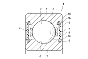
- Fig. 2 shows an example of a bearing with measures taken to prevent grease from scattering inside the bearing and intrusion of water and foreign substances from outside the bearing.
- the gap between the outer ring 1 and the inner ring 2 is sandwiched by a pair of bearing rings, which are seal members 3, from both ends in the axial direction.
- the seal groove portion 5 is formed on the outer peripheral surface of the inner ring 2 on the fixed side.
- the inner peripheral edge portion (seal lip portion 3a) of the annular seal member 3 is inserted into the seal groove portion 5.
- the sealed bearing 4 is prevented from leaking grease from the inside of the bearing and from entering water, foreign matter, or the like from the outside of the bearing.
- Patent Documents 1 to 4 Various methods have been proposed for removing foreign matter in such bearings (for example, Patent Documents 1 to 4).
- the forming tool is used for the cutting process before the heat treatment. This reduces burrs and burrs in the conventional bite feeding direction and makes it difficult for the surface layer to fall off or foreign matter to enter.
- barrel processing is performed to remove minute burrs and foreign substances.
- the inner ring is rotated while moving the high-pressure liquid jet injection pipe in parallel with the axis of the inner ring.
- the high-pressure liquid jet injection pipe is rotated around the inner ring, and the high-pressure liquid jet injected from the high-pressure liquid jet injection pipe is applied to the outer peripheral surface of the inner ring to clean the outer peripheral surface including the ball rolling surface of the inner ring.
- an ultrasonic vibration plate is provided in a cleaning tank filled with a cleaning liquid, and ultrasonic waves oscillated by the ultrasonic vibration plate are applied to a ring-shaped part arranged in the cleaning tank. A foreign object adhering to the ring-shaped part is removed by applying the ring.
- Japanese Patent Laid-Open No. 2004-100754 Japanese Patent Laid-Open No. 2003-326223 Japanese Patent Laid-Open No. 2002-59096 Japanese Patent Laid-Open No. 2018-35907
- Patent Document 2 In the ball bearing cleaning method of Patent Document 2, there is a risk that the equipment will be large because it injects fluid at high pressure and prevents fluid from leaking out of the cleaning equipment. Further, it is necessary to maintain the cleanliness of the cleaning fluid. Further, Patent Document 2 describes that pure water is used, which may increase running costs.
- An object of the present invention is to perform a foreign matter removal method for a bearing component, which can be operated inexpensively and stably without using a foreign matter generation source or large-scale equipment, and can reliably remove foreign matter even to a minute portion, and (EN) A foreign matter removing device and a bearing component from which foreign matter is removed by the method.
- the present invention has the following configurations. (1) A step of rotating a bearing component made of steel around an axis, Irradiating the rotating bearing component with pulsed laser light having an energy density of 0.3 to 4.0 J/cm 2 on the irradiation surface, A step of scanning the surface of the bearing part with the pulsed laser beam by relative movement of the bearing part and the pulsed laser beam along the axis to remove foreign matter on the surface of the bearing part. Foreign matter removal method. According to this foreign matter removing method for the bearing component, the rotating bearing component is irradiated with the pulsed laser light having an energy density of 0.3 to 4.0 J/cm 2 on the irradiation surface to scan the surface of the bearing component. ..
- (10) A bearing manufactured by using the method for removing foreign matter from a bearing component according to any one of (1) to (9).
- (11) A machine manufactured using the bearing described in (10).
- (12) A vehicle manufactured using the bearing according to (10).
- a chuck that detachably holds a bearing component made of steel, A rotating main shaft that rotationally drives the bearing component gripped by the chuck, A laser oscillator that generates pulsed laser light, A laser condensing head equipped with a condensing lens for condensing the pulsed laser light and irradiating the surface of the bearing component with the pulsed laser light with an energy density of 0.3 to 4.0 J/cm 2 on the irradiation surface.
- a foreign matter removing device for a bearing component which removes foreign matter on the surface of the bearing component by irradiation of the pulsed laser light.
- the bearing component gripped by the chuck is rotationally driven.
- the pulsed laser light emitted from the laser oscillator is applied to the surface of the rotating bearing component with an energy density on the irradiation surface of 0.3 to 4.0 J/cm 2 .
- the pulsed laser light is scanned on the surface of the bearing component by the relative movement of the laser focusing head and the bearing component by the feeding mechanism.
- foreign substances such as oxide film and dust on the non-processed surface of the surface layer are removed.
- it is possible to inexpensively and stably remove foreign matter without using large-scale equipment.
- the pulsed laser light is made into condensed light having a deep focal depth or parallel light, whereby the foreign matter can be efficiently removed regardless of the unevenness of the surface.
- the spiral scanning along the axis of the bearing component can be accurately and easily performed, and the tact time for removing the foreign matter can be improved by highly efficient scanning.
- the foreign matter removing device for a bearing component according to any one of (13) to (15), further including a dust collecting unit that sucks fumes generated from the bearing component by irradiation with the pulsed laser light.
- the foreign matter removing device for the bearing component can prevent the generated fumes from adhering to the surface of the bearing component again.
- a method of manufacturing a bearing component having a regular pattern of a large number of dots A step of rotating the bearing component made of steel around an axis; Irradiating the rotating bearing component with pulsed laser light having an energy density of 0.3 to 4.0 J/cm 2 on the irradiation surface, Scanning the pulsed laser light on the surface of the bearing component by relative movement of the bearing component and the pulsed laser light along the axis, and removing foreign matter on the surface of the bearing component; And a method of manufacturing a bearing component including.
- this bearing component manufacturing apparatus it is possible to efficiently remove foreign matter generated when the genuine product identification mark is formed on the bearing component.
- a manufacturing device of a bearing component having a regular pattern of a large number of dots A chuck for detachably gripping the bearing component made of steel, A rotating main shaft that rotationally drives the bearing component gripped by the chuck, A laser oscillator that generates pulsed laser light, A laser condensing head equipped with a condensing lens for condensing the pulsed laser light and irradiating the surface of the bearing component with the pulsed laser light with an energy density of 0.3 to 4.0 J/cm 2 on the irradiation surface.
- a feed mechanism that relatively moves the laser focusing head and the bearing component in the axial direction of the bearing component, and causes the pulsed laser light to scan the surface of the bearing component.
- a bearing component manufacturing apparatus for removing foreign matter on the surface of the bearing component by irradiation of the pulsed laser light (30) The apparatus for manufacturing a bearing component according to (29), wherein the pulsed laser light is condensed light or parallel light having a depth of focus of 0.1 mm or more. (31) The bearing component manufacturing apparatus according to (29) or (30), wherein the feeding mechanism moves the laser focusing head along an axis of the bearing component. (32) The apparatus for manufacturing a bearing component according to any one of (29) to (31), further including a dust collecting unit that sucks fumes generated from the bearing component by irradiation with the pulsed laser light. (33) The bearing component manufacturing apparatus according to (32), further including an air blower that blows gas to the dust collector.
- dots are formed with a desired density. Further, the pitch can be adjusted by the rotation speed of the bearing component, the laser scanning speed, the repetition frequency, the irradiation time, and the like.
- the todds can be densely arranged to remove the foreign matter more uniformly.
- a bearing comprising the bearing component according to any one of (34) to (39). (41) A machine having the bearing according to (40). (42) A vehicle having the bearing according to (40).
- the present invention it is possible to operate inexpensively and stably without using a source of foreign matter or large-scale equipment, and it is possible to reliably remove foreign matter even to a minute portion.
- FIG. 3 is a cross-sectional configuration diagram of a motor in which a bearing is applied to support a rotating shaft. It is a graph which shows the correlation of an energy density and the amount of removal. It is a schematic explanatory drawing which shows the example of the unit shape of the pattern formed in a bearing component to (A)-(D). It is a schematic explanatory drawing which shows the example of the pattern formed in a bearing component to (A)-(D).
- FIG. 1 is a schematic configuration diagram of a foreign matter removing device for a bearing component.
- the foreign matter removing device 100 for a bearing component of this configuration includes a rotating main shaft 11, a chuck 13, a laser oscillator 15, a laser focusing head 17, a feeding mechanism 19, and a dust cleaner 21 as a dust collecting portion. ..
- the bearing parts shown here are a pair of bearing rings that constitute the above-mentioned sealed bearing 4 of the outer ring rotating type shown in FIG. 2.
- the inner ring 2 which is one of the bearing rings is shown as a work W.
- the seal member 3 is attached to the axial end portions of the inner ring 2 and the outer ring 1 which is the other bearing ring so as to sandwich the inner ring 2 and the outer ring 1 from both sides in the axial direction. ..
- the pair of seal members 3 seal the bearing space between the inner ring 2 and the outer ring 1.
- the seal member 3 has a ring-shaped core metal 8 and a ring-shaped elastic portion 9 that covers the core metal 8.
- NBR acrylonitrile-butadiene rubber
- silicon rubber or the like is used.
- the seal lip portion 3a extends from the elastic portion 9, and a side surface lip facing the seal groove portion 5 formed in the inner ring 2 is formed at the extending tip of the seal lip portion 3a.
- the ring-shaped outer peripheral edge portion 3b of the seal member 3 is fixed to the inner peripheral groove 10 formed in the outer ring 1 on the rotating side.
- a seal groove portion 5 into which the seal lip portion 3a of the seal member 3 is inserted is formed on the outer peripheral surface of the inner ring 2.
- the seal member 3 may be a contact type in which the side surface side lip of the seal lip portion 3a is pressed against the inner wall of the seal groove portion 5 by the elastic force of the elastic portion 9, and is in a non-contact state with the seal groove portion 5 of the inner ring 2. It may be a contact type.
- the inner ring 2 will be described as an example of the bearing component, but the present invention is not limited to this, and the outer ring 1 and other bearing components such as a cage may be used. Further, in the following description, the inner ring 2 as a bearing component is referred to as a "work W", and the seal groove portion 5 is referred to as a "work groove portion 25". In this case, the foreign matter removing device 100 is used in a process of manufacturing a bearing in which a bearing component is processed and assembled, and removes foreign matter from the surface of the bearing component forming the bearing.
- the rotating main shaft 11 is rotatably supported by a supporting member such as a column erected on a base and is rotated at a high speed by a drive motor (not shown).
- the rotary spindle 11 supports the ring-shaped work W by the chuck 13 as in the spindle spindle device of a machine tool, for example.
- the chuck 13 is fixed to the rotating spindle 11, and holds the ring-shaped work W coaxially and detachably.
- the chuck 13 is provided with, for example, three grip claws 27 that are each movable in the radial direction at equal intervals in the circumferential direction.
- the gripping claw of the chuck 13 is expanded on the inner diameter side of the work W, so that the work W is gripped coaxially with the rotary spindle 11.
- the chuck 13 may be a gripping mechanism of another type such as an air chuck or a magnet chuck, in addition to the manual one described above.
- the laser oscillator 15 is preferably capable of outputting pulsed laser light with a pulse width of femtosecond order to 200 nanoseconds.
- a nanosecond laser oscillator is used as an example.
- the laser oscillator 15 only needs to be capable of generating a pulse having an energy density of 4.0 J/cm 2 or less, capable of performing heat mode exposure, and capable of emitting high-density energy light, such as a fiber laser, a solid-state laser, or a semiconductor laser. Can be used.
- a general nanosecond laser oscillator has a pulse width of several tens of nanoseconds and can generate a pulse of 0.3 to 4.0 J/cm 2 on the irradiation surface for the reason that the energy density will be described later. ..
- a laser oscillator capable of outputting picosecond, femtosecond, or attosecond-order ultrashort pulse laser light can be used as the laser oscillator 15.
- the pulsed laser light will be referred to as “short pulsed laser light”.
- the "short pulse laser light” includes picosecond, femtosecond, and attosecond order "ultrashort pulse laser light".
- the laser focusing head 17 is connected to the laser oscillator 15 via an optical fiber 31.
- the short pulse laser light output from the laser oscillator 15 is transmitted to the laser focusing head 17 through the optical fiber 31.
- the laser condenser head 17 includes a condenser lens 33.
- the condenser lens 33 condenses the short pulse laser light transmitted by the optical fiber 31 into a condensed light having a deep focal depth (large value) or a parallel light.
- the surface of the ring-shaped work W is irradiated with the obtained condensed light or parallel light.
- the short pulse laser beam 29 is applied to the work groove portion 25 as spot light having a diameter of, for example, about 50 to 100 ⁇ m. When the spot diameter is within the above range, it is possible to selectively irradiate a fine portion (work groove 25 or the like) on the surface of the work.
- the feed mechanism 19 is capable of relatively moving the laser focusing head 17 and the rotary spindle 11 at least in a direction (Z direction) along the rotation axis L of the rotary spindle 11 (axial center of the ring-shaped workpiece W).
- the feed mechanism 19 has a function of relatively moving in a direction (X direction) orthogonal to the rotation axis L of the rotary main shaft 11 as necessary, and a Y direction orthogonal to the Z direction and the X direction (the direction perpendicular to the paper surface of FIG. 1). It may have a function of swinging about (in the axial direction).
- the feeding mechanism 19 shown in FIG. 1 is configured to move the laser focusing head 17 with respect to the rotating main shaft 11 that is rotatably installed. That is, the moving table 35 is a stage capable of moving the above laser condensing head 17 in the Z direction with high accuracy.
- the moving table 35 is moved in the X direction for positioning adjustment of the laser focusing head 17, an orthogonal biaxial stage is used. Further, when the laser focusing head 17 is swung around the Y direction, a rotary stage is also used.
- the short pulse laser light 29 can be irradiated to the work W from a direction inclined from the X direction. In this case, the laser condensing head 17 can irradiate the short pulse laser light 29 to, for example, the end surfaces of the work W on both sides in the axial direction and the inner peripheral surface of the work W.
- the optical path of the short pulse laser light 29 can be changed by an optical means such as a galvanometer mirror, a polygon mirror, a condenser mirror.
- the dust cleaner 21 collects the fumes generated from the work surface by the irradiation of the spot light of the short pulse laser light 29.
- the dust cleaner 21 may be mounted on, for example, a drive device (not shown) that changes the direction of the suction port.
- the driving device moves the dust cleaner 21 in synchronization with, for example, the feeding mechanism 19 of the laser condensing head 17, thereby always arranging the suction port at an optimum position that is apart from the irradiation position of the spot light by a predetermined distance.
- the dust cleaner 21 can always suck the fumes with high efficiency and enhance the dust collection effect.
- the dust cleaner 21 blows a gas toward the dust collecting port to control the air flow in the field and can collect various objects such as smoke and spatter generated by laser processing.
- air may be blown near the laser processing point. According to this, it is possible to prevent the plasma or the like scattered in the air from reattaching to the surface of the work W.
- the above-mentioned gas may be the atmosphere or oxygen as long as it can create a flow of air. Further, since the spatter and the like blown by the blown air are collected, the dust after cooling by the blown air is collected and is less likely to be affected by heat.
- the foreign matter removing apparatus 100 includes a control unit 37 that integrally controls the above-described units.
- the control unit 37 is electrically connected to the drive unit of the rotary spindle 11, the laser oscillator 15, and the feed mechanism 19.
- the control unit 37 controls the output of the laser oscillator 15 to increase or decrease in synchronization with the rotation speed of the rotating spindle 11. Further, the control unit 37 controls on/off of driving of the feed mechanism 19, a moving direction, a moving speed, and the like.
- the laser condensing head 17 continuously irradiates the work groove portion 25 of the work W with spot light by the short pulse laser light 29 in a spiral shape by the movement in the Z direction by the feeding mechanism 19.
- control unit 37 appropriately determines the rotation speed of the bearing ring, the feed speed of the laser focusing head 17, and the repetition frequency of the short pulse laser in consideration of pulse overlap.
- the energy density Ed of the short pulse laser light is expressed by Ep/S, where Ep is the pulse energy of the laser and S is the irradiation area. Since there is an upper limit to the pulse energy Ep that can be irradiated by the foreign matter removing device, it is necessary to adjust the irradiation area S below a certain value in order to obtain the required energy density Ed. Therefore, in the foreign matter removing device having the above configuration, the irradiation area of the short-pulse laser light is set to be equal to or less than a certain irradiation area (limit irradiation area) capable of removing the foreign matter.
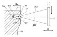
- the irradiation area S of the short pulsed laser light 29A on the work surface 39 is equal to or less than the limit irradiation area. Adjust so that This adjustment can be changed, for example, by selecting the condenser lens 33 (see FIG. 1) of the laser condenser head 17.
- the condenser lens 33 see FIG. 1 of the laser condenser head 17.
- the irradiation area S on the work surface 39 is the limit irradiation area, that is, the work surface 39 is the limit position of the depth of focus DF. It may be arranged within the range of the depth of focus DF, such as the center of the center.
- the short pulse laser light 29 does not have to be condensed light.
- a short pulse laser beam 29B composed of parallel light whose beam size perpendicular to the optical axis direction is equal to or smaller than the limit irradiation area may be used.
- the laser condensing head 17 is scanned in the direction perpendicular to the optical axis direction (X direction) from the state shown in FIG. 3A, and at the position of the groove 41 formed in the work W, Consider irradiating the short pulsed laser light 29A of condensed light.
- the short pulse laser beam 29A is irradiated toward the groove bottom 41a of the groove 41 having the depth Dw, but the irradiation spot spreads at the groove bottom 41a, and the irradiation area Sa at the groove bottom 41a exceeds the limit irradiation area. Will end up. In that case, the foreign matter on the groove bottom portion 41a cannot be removed.
- the depth of focus DF of the short pulse laser beam 29A it is preferable to preset the depth of focus DF of the short pulse laser beam 29A to a deep depth of focus DF that is equal to or greater than the groove depth Dw from the surface of the work W (the uneven width of the work).
- the short pulse laser beam 29A is always irradiated to the groove bottom 41a in an irradiation area equal to or less than the limit irradiation area, and the foreign matter on the work surface 39 and the groove bottom 41a can be removed.
- the short-pulse laser beam 29B of parallel light the irradiation area below the limit irradiation area is maintained regardless of the surface position of the work W.
- the distance Ds in the optical axis direction between the surface position of the work W irradiated with the short pulse laser light 29A and the focus position P of the short pulse laser light 29A that is the condensed light is considered. More preferably. Specifically, it is set so that the focal depth DF has a length of Dw/2 on one side with the focus position P of the short pulse laser light 29A as the center. Further, the depth of focus DF is set according to the surface shape of the work W. That is, when the irradiation position (X-direction position) on the work surface changes during scanning with the short pulse laser light 29A, the focal depth DF is set to a value equal to or larger than the maximum change width of the irradiation position.
- the irradiation surface of the short-pulse laser beam 29A can be reliably set within the focal depth DF, and the entire work W can be irradiated with an irradiation area that is less than or equal to the limit irradiation area. As a result, the foreign matter can be removed evenly.
- the depth of focus of the short pulse laser light 29 used in this configuration it is preferable to set to 0.1 mm or more.
- the depth of focus may be set to 10 mm or more, or 20 mm or more, depending on the uneven shape of the work. Further, when the depth of focus is made relatively shallow, the depth of focus may be 0.3 to 0.5 mm, or 2 to 3 mm.
- the laser focusing head 17 is moved as shown in FIG. 3C.
- the irradiation area S of the surface of the work W by the short pulse laser light 29A that is the condensed light is adjusted. That is, in the control unit 37 shown in FIG. 1, the positional change in the X direction of the work W to be a foreign matter removal target (surface unevenness, etc.) exceeds the allowable depth of focusing of the short pulse laser light 29 (limit irradiation area).
- the feeding mechanism 19 moves the laser condensing head 17 in the X direction in accordance with the amount of position change to change the condensing position.
- the movement of the laser condensing head 17 in the X direction is performed by focusing on the focus having the shorter moving distance (the focus on the rear side in the case of FIG. 3C) of the focus on the front and the rear of the optical path, depending on the position of the unevenness on the work surface. It is preferable to control the irradiation position. According to this control, the moving distance in the X direction can be shortened and the speed can be increased.
- the movement control in the X direction can be performed by the control unit 37 determining the movement amount of the laser focusing head 17 based on the shape data of the workpiece W input in advance.
- a sensor that detects the position of the surface of the workpiece in the X direction may be provided and the movement amount may be determined according to the output from the sensor.
- Such movement control in the X direction by the feed mechanism 19 is particularly effective when the unevenness of the work W is large.
- a ring-shaped work W is coaxially attached to the chuck 13 of the rotary spindle 11 shown in FIG. 1, and the work W is rotationally driven around the axis (rotational driving step).
- a pair of work groove portions 25 is recessed. In this configuration, the oxide film or oil film remaining in the work groove 25, or foreign matter such as burrs or dust is removed.
- the laser oscillator 15 outputs the short pulse laser light 29.
- the short pulse laser light 29 from the laser oscillator 15 is transmitted to the laser condensing head 17 through an optical fiber 31, and is converted into condensed light or parallel light by a condensing lens 33 of the laser condensing head 17, and the work is
- the W is irradiated in a spot shape.
- the output of the laser oscillator 15 is controlled by the control unit 37 so that the spot light obtained by focusing the short pulse laser light 29 has an energy density of 0.3 to 4.0 J/cm 2 , and the work W Irradiation (irradiation step of short pulse laser light).
- the control unit 37 rotationally drives the rotary spindle 11, while relatively moving the rotary spindle 11 and the laser condensing head 17 along the Z direction parallel to the rotation axis L, and spotting by the short pulse laser beam 29.
- the surface of the work W is scanned with light.
- the control unit 37 sets the rotation speed of the work W, the feed speed of the laser condensing head 17, and the pulse frequency of the short-pulse laser light 29 such that the overlap (overlap) of the pulses is a target value (for example, 30 to 70). %).
- the controller 37 drives the dust cleaner 21 to suck the generated fumes to collect the dust.
- the spot light of the short pulse laser light 29 is continuously irradiated onto the surface of the ring-shaped work W that is rotationally driven.
- foreign matter such as an oxide film, an oil film, burrs, and dust on the non-processed surface of the surface layer is ablated (evaporated or sublimated) by the short pulse laser light 29.
- the fumes generated by this are collected by the dust cleaner 21, and the floating fumes do not adhere to the work surface.
- the energy density Q of the spot light irradiating the work surface is set to 0.3 to 4.0 J/cm 2 , only the foreign matter can be selectively removed without damaging the base material.
- the means for removing the foreign matter is the laser beam, it becomes possible to irradiate spot-like light only to a minute portion such as the work groove 25 in particular. Therefore, foreign matter can be easily and surely removed even in a region where ultrasonic waves or the like are hard to reach.
- the spot light is scanned while rotating the work W, even if the surface to be removed is large, the spot light can be evenly irradiated and the foreign matter can be reliably removed. Further, by arbitrarily changing the scanning pattern of the spot light according to the part of the foreign matter removal target, the foreign matter can be easily removed in any area. For example, even when a portion of the work surface where irradiation with the short pulse laser light is not desired is mixed, the irradiation area can be arbitrarily selected by controlling the laser on/off. In barrel processing and shot blasting, it was necessary to mask the foreign matter removal unnecessary area on the surface of the work W, but when using a laser, it is only necessary to turn on/off the laser light, and masking is unnecessary. Therefore, the labor can be saved and the cost can be reduced.
- the feed mechanism 19 for moving the laser condensing head 17 is controlled only on the Z axis.
- the configuration and control of the foreign substance removing apparatus 100 can be simplified. According to this, it is possible to reduce the takt time of the foreign matter removing process by the foreign matter removing apparatus 100 and reduce the apparatus cost.
- the energy density on the irradiation surface of the short pulse laser light is set to 0.3 to 4.0 J/cm 2, and the condensed light or the parallel light having a deep focal depth is used, so that the non-uniformity or the thickness is caused. It is possible to reliably remove the oxide film on the processed surface and foreign matter that has adhered. Further, it is not affected by the unevenness of the work W, the rotation accuracy of the rotary shaft, and the centering accuracy when gripping the work.
- the foreign matter removing apparatus 100 having this configuration, it is possible to always perform stable foreign matter removal unless the laser oscillator 15 deteriorates.
- the laser light itself does not become a source of foreign matter generation, secondary foreign matter generation due to the laser light does not occur in regions other than the region where the foreign matter is removed by the laser light.
- the equipment can be simplified as compared with the foreign matter removing method using cleaning water, and the foreign matter can be safely applied to a minute portion such as the work groove portion 25. Can be removed.
- the cleaning liquid is unnecessary, it is not necessary to manage the cleanliness of the cleaning liquid. Further, there is no tool cost or solvent cost, and it can be operated at a low running cost with almost only power consumption.
- the foreign matter removing method using the foreign matter removing apparatus 100 described above removes foreign matter from the bearing surface such as the bearing 4 with a seal as shown in FIG. 2, whereby a high-quality bearing can be manufactured.
- the process of processing the seal groove portion of the inner ring has been described, but the area for removing foreign matter may be the outer peripheral surface other than the seal groove or the inner peripheral surface. It may also be the inner peripheral surface of the outer ring. Further, it may be the outer circumference of the inner ring of the bearing without the seal groove, or the inner circumference of the outer ring.
- the foreign matter removing apparatus 100 of this configuration it is possible to operate inexpensively and stably without using a source of foreign matter and large-scale equipment, and to reliably remove foreign matter even to minute parts. Further, since the machining is non-contact, no new foreign matter generation source is generated, no tool wear like a normal tool occurs, and machining can be performed under stable machining conditions. Further, by selecting the pulse width and the laser output value, it is possible to realize processing that does not damage the base material of the bearing ring, so that it is possible to reliably remove foreign matters and oxide films that could not be removed with a weak energy density. Moreover, it is possible to stably remove foreign matters and oxides even on the uneven surface.
- bearings with foreign matter removed The bearing from which the foreign matter has been removed by the foreign matter removing method described above can be suitably applied to, for example, the bearings 100A and 100B that support the rotating shaft 63 of the motor 61 shown in FIG.
- the motor 61 is a brushless motor, and has a cylindrical center housing 65 and a substantially disc-shaped front housing 67 that closes one open end of the center housing 65.
- a rotatable shaft 63 is supported inside the center housing 65 along the axis thereof via bearings 100A and 100B arranged at the bottom of the front housing 67 and the center housing 65.
- a rotor 69 for driving a motor is provided around the rotary shaft 63, and a stator 71 is fixed to the inner peripheral surface of the center housing 65.
- the motor 61 having the above-described configuration is generally mounted on a machine or a vehicle and rotationally drives a rotating shaft 63 supported by bearings 100A and 100B. That is, it is possible to manufacture a machine or a vehicle by using the bearing manufactured by the above-described method for removing foreign matter from the bearing ring.
- a machine having a rotating portion various manufacturing devices, for example, a screw device such as a ball screw device, and an actuator (a combination of a linear motion guide bearing and a ball screw, an XY table, etc.), etc.
- Rotation support part of a linear motion device a rotation support part of a steering device such as a steering column, a universal joint, an intermediate gear, a rack and pinion, an electric power steering device, and a worm speed reducer, and further, an automobile, a motorcycle, a railroad, etc.
- the rotation support part of the vehicle is mentioned.
- the bearing of this configuration can be suitably applied to a portion that relatively rotates, which can lead to improvement of product quality.
- the formation of the genuine product mark on the bearing component can be achieved by, for example, increasing the energy density of the laser light of the apparatus of FIG. 1 to a state necessary for mark formation, and along the trajectory of the laser light on the bearing component.
- a pattern composed of a large number of dots is formed.
- the pattern is preferably a pattern in which the same basic unit shape that is the basis is repeatedly formed regularly by shifting the position, but may be random.
- FIG. 6 is a schematic explanatory view showing an example of a unit shape of a pattern formed on a bearing part, which is shown in (A) to (D).
- (A) is a circle
- (B) is a square
- (C) is a rectangle
- (D) is a star.
- the unit shape is not limited to the above-mentioned shape, and any shape can be adopted.
- FIG. 7 is a schematic explanatory view showing examples (A) to (D) of patterns formed on bearing parts.
- FIG. 7A shows a pattern in which circular unit shapes are repeatedly arranged in a predetermined constant pitch in two directions orthogonal to each other (herein referred to as vertical and horizontal directions).
- (B) of FIG. 7 shows a pattern in which one side of a square, which is a unit shape, is arranged with vertical and horizontal pitches
- (C) of FIG. 7 shows the length of the short side of the rectangle with the horizontal pitch and the long side. It is a pattern in which a length shorter than the side is arranged as a vertical pitch.
- FIG. 7D shows a pattern in which the star-shaped unit shapes are arranged vertically and horizontally at a predetermined constant pitch.
- the pattern may be line-symmetric, point-symmetric, or not symmetrical.
- the unit shape of the pattern may be the same shape and provided at regular pitches, or a plurality of different basic shapes may be provided at predetermined pitches. Further, the unit shapes may be arranged vertically and horizontally at pitches having the same or different lengths. Then, the dots of the pattern may partially overlap or may be in contact with each other.
- the maximum width of the unit shape of such a pattern is preferably 10 mm or less, more preferably 5 mm or less, and further preferably 1 mm or less.
- the same basic shape described above can be generated using a laser scanning mechanism such as a galvano scanner, but it is preferable to generate only the mechanical feeding mechanism configured by a known technique using a cam or the like. ..
- the pattern pitch can be adjusted by the work rotation speed, laser scanning speed, repetition frequency, and irradiation time.
- the regular product mark having such a pattern can be provided on the chamfered portion of the bearing component, the inner diameter of the outer ring, or a part or the entire outer diameter of the inner ring.
- Table 1 shows the results of removing foreign matters with laser beams of various energy densities.
- FIG. 5 is a graph showing the correlation between the energy density and the amount of foreign matter removed.
- the removal amount data shown in FIG. 5 shows three types of data in which the pulse repetition frequency of the short pulse laser light is 100 kHz, 50 kHz, and 20 kHz.
- a fiber laser with a pulse width of 30 ns was used in this example.
- the foreign matter removal target was the seal groove portion of the inner ring of the deep groove ball bearing (bearing part number #6203).
- the inner ring is a steel material made of SUJ2 (high carbon chromium bearing steel material).
- the removal amount shown in FIG. 5 is a radius value measured using a non-contact type shape measuring machine (Taylor Hobson non-contact 3D profiler CCIMP-HS).
- the present invention is not limited to the above-described embodiments, and the configurations of the embodiments may be combined with each other, or may be modified and applied by those skilled in the art based on the description in the specification and well-known techniques.
- the invention is planned and is included in the scope of protection required.
- the irradiation spot of the short pulse laser light is not limited to a circular shape, and may be, for example, a square, a rectangle such as a rectangle, a line, a plurality of points or lines, or a surface.
- the present invention is not limited to the bearing with a seal groove, and is also suitable for a bearing without a seal groove and other types of bearings. Applicable to
Landscapes
- Engineering & Computer Science (AREA)
- General Engineering & Computer Science (AREA)
- Mechanical Engineering (AREA)
- Physics & Mathematics (AREA)
- Optics & Photonics (AREA)
- Plasma & Fusion (AREA)
- Manufacturing & Machinery (AREA)
- Laser Beam Processing (AREA)
Abstract
鋼材からなる軸受部品を軸芯回りに回転させる工程と、照射面におけるエネルギ密度が0.3~4.0J/cm2のパルスレーザ光を、回転する軸受部品の表面に照射し、軸受部品とパルスレーザ光との軸芯に沿った相対移動により、パルスレーザ光を軸受部品の表面で走査させ、軸受部品の表面の異物を除去する。
Description
本発明は、軸受部品と、それに付着する異物を除去する方法及び装置に関する。
軸受の端面、転動面、内径面及び外径面以外の面(例えば、シール板溝、外輪内径面、内輪外径面、肩R部等)には、製品完成の段階で熱処理後の非加工面がそのまま残存している場合がある。また、非加工面は、加工面と比較して表面粗さが大きいため、外部から混入した異物が表面に付着しやすい。
図2に、軸受内部からのグリース飛散や、軸受外部からの水や異物等の侵入の予防対策を施した軸受の一例を示す。この軸受では、外輪1と内輪2との間の隙間を、軸方向の両端側から一対の軸受リングであるシール部材3で挟み込んでいる。このようなシール付き軸受4は、例えば外輪1が回転側となる場合、固定側となる内輪2の外周面にシール溝部5が形成される。このシール溝部5には、円環形状のシール部材3の内周縁部(シールリップ部3a)が挿入される。これにより、シール付き軸受4は、軸受内部からのグリース漏れや、軸受外部からの水や異物等の浸入が防止される。
しかし、シールがシール溝部と摺動するために、溝内に残存する異物や溝表面の酸化膜層が、溝表面からこそぎ落とされやすい。また、微小な異物が軸受の転動面に混入すると、ボールと転動面との間に噛みこまれて異音を発生したり、転動面にキズを付けたりして、音響性能や軸受寿命を悪化させるおそれがある。そのため、効果的な酸化膜や異物の除去方法が求められていた。
このような軸受における異物の除去について、種々の方法が提案されている(例えば、特許文献1~4)。
特許文献1の軸受装置における外輪内面の滑面仕上処理方法では、熱処理前の切削加工に総型バイトを用いる。これにより、従来のバイト送り方向のカエリやバリを減らし、表面層の脱落や異物混入を生じにくくしている。さらに、微小なバリや異物を除去するためにバレル処理を施している。
特許文献1の軸受装置における外輪内面の滑面仕上処理方法では、熱処理前の切削加工に総型バイトを用いる。これにより、従来のバイト送り方向のカエリやバリを減らし、表面層の脱落や異物混入を生じにくくしている。さらに、微小なバリや異物を除去するためにバレル処理を施している。
特許文献2のボールベアリングの洗浄方法では、内輪の軸心と平行に高圧液体ジェット噴射管を移動させながら、内輪を回転させる。もしくは高圧液体ジェット噴射管を内輪の回りで回転させ、高圧液体ジェット噴射管から噴射される高圧液体ジェットを内輪の外周面に当てて、内輪のボール転動面を含む外周面を洗浄する。
特許文献3のリング状部品の洗浄方法では、洗浄液の満たされた洗浄槽に超音波振動板を設け、この超音波振動板によって発振される超音波を、洗浄槽内に配置したリング状部品に当て、リング状部品に付着した異物を除去する。
特許文献4の車輪用軸受装置における内輪の内周と外周の処理方法では、内周と外周の角部に、レーザピーニング処理によって圧縮残留応力を付与している。
しかしながら、特許文献1の軸受装置における外輪内面の滑面仕上処理方法では、バイトの摩耗や、バッチ処理であるバレル加工の特性により、安定した結果が得られにくい。また、バイトやバレルのメディア自体が異物の発生源となってしまうおそれがある。
特許文献2のボールベアリングの洗浄方法では、流体を高圧で噴射することや、洗浄設備外への流体漏れを防止するため、設備が大掛かりになるおそれがある。また、洗浄用の流体の清浄度を維持する必要がある。さらに、特許文献2には純水を使用すると記載されており、ランニングコストが嵩むおそれがある。
特許文献3のリング状部品の洗浄方法では、超音波が、波長とリングの形状によってはターゲットとしている部位に十分届かない。また、高圧流体を用いた方法と同様に、洗浄液の清浄度を維持する必要がある。
特許文献4の車輪用軸受装置における内輪の内周と外周の処理方法では、圧縮の残留応力を付与するレーザピーニングを用いている。そのため、レーザによる衝撃波を利用するには、液中で加工を行う必要がある。また、レーザ照射はハブ軸受に限られているという問題がある。
その他、砥石やブラシで表面層を削り取る方法も考えられるが、工具が異物源となりかねない上に、シール溝部のような微小部位では、部位の形状に合わせた工具の作製や、工具の状態の維持に困難を伴う。
また、近年、模倣品による被害が拡大しており、軸受等の製品も例外ではない。そのため、製品に正規品識別マークを付して模倣品の発見を容易にする取り組みも行われているが、鋼製品へのマーク形成時に異物が発生し、また、マークの存在が異物を離れ難くしている場合がある。
また、近年、模倣品による被害が拡大しており、軸受等の製品も例外ではない。そのため、製品に正規品識別マークを付して模倣品の発見を容易にする取り組みも行われているが、鋼製品へのマーク形成時に異物が発生し、また、マークの存在が異物を離れ難くしている場合がある。
本発明の目的は、異物の発生源や大掛かりな設備を使用せず、安価に且つ安定して運用でき、しかも、微小部位に対しても確実に異物除去が可能な軸受部品の異物除去方法及び異物除去装置、並びに、その方法で異物が除去された軸受部品を提供することにある。
本発明は下記の構成からなる。
(1) 鋼材からなる軸受部品を軸芯回りに回転させる工程と、
照射面におけるエネルギ密度が0.3~4.0J/cm2のパルスレーザ光を、回転する前記軸受部品に照射する工程と、
前記軸受部品と前記パルスレーザ光との前記軸芯に沿った相対移動により前記パルスレーザ光を前記軸受部品の表面で走査させ、前記軸受部品の表面の異物を除去する工程と、を含む軸受部品の異物除去方法。
この軸受部品の異物除去方法によれば、照射面におけるエネルギ密度が0.3~4.0J/cm2のパルスレーザ光を、回転する軸受部品に照射することで、軸受部品の表面で走査させる。これにより、パルスレーザ光が照射された軸受部品の表面では、表層の非加工面の酸化膜や塵埃等の異物が除去される。このように、異物の発生源とならないレーザ光を用いることで、大掛かりな設備を使用せず、安価に且つ安定した異物除去が可能となる。
(2) 前記パルスレーザ光は、焦点深度が0.1mm以上の集光光又は平行光である(1)に記載の軸受部品の異物除去方法。
この軸受部品の異物除去方法によれば、パルスレーザ光を焦点深度の深い集光光又は平行光にすることで、表面の凹凸によらずに、効率よく異物を除去できる。
(3) 前記パルスレーザ光を、前記軸受部品の軸芯に沿って移動させる(1)又は(2)に記載の軸受部品の異物除去方法。
この軸受部品の異物除去方法によれば、軸受部品の軸芯に沿った螺旋走査を正確且つ簡単に行え、高効率な走査によって異物除去のタクトアップが図れる。
(4) 前記パルスレーザ光の照射により前記軸受部品から発生したヒュームを吸引して、前記パルスレーザ光の照射面から前記ヒュームを除去する(1)~(3)のいずれか1つに記載の軸受部品の異物除去方法。
この軸受部品の異物除去方法によれば、発生したヒュームが再び軸受リングの表面に付着することを防止できる。
(5) 前記パルスレーザ光の前記軸受部品表面での走査が、機械的な送り機構のみで行われる(1)に記載の軸受部品の異物除去方法。
この軸受部品の異物除去方法によれば、ガルバノスキャナ等を用いることなく、パルスレーザ光の走査が行われる。
(6) 前記ヒュームを吸引する集塵部に向けて気体を送風する第一の送風機構を有する(4)に記載の軸受部品の異物除去方法。
この軸受部品の異物除去方法によれば、集塵部の口に向けて気体を送風することにより、場の気体流れを制御し、加工により生じた煙、スパッタ等様々な物体を集塵部に回収させることができる。
(7) 前記パルスレーザ光の照射位置に向けて気体を送風する第二の送風機構を有する(1)に記載の軸受部品の異物除去方法。
この軸受部品の異物除去方法によれば、空気中に飛散したプラズマ等がワーク表面に再付着することを防止できる。
(8) 前記気体は大気である(6)又は(7)に記載の軸受部品の異物除去方法。
この軸受部品の異物除去方法によれば、空気の流れをつくり、異物の除去を促進できる。
(9) 前記パルスレーザ光の前記軸受部品への照射は、前記軸受部品に形成された軌道面に近い方から行われる(1)に記載の軸受部品の異物除去方法。
この軸受部品の異物除去方法によれば、軌道面への熱影響を抑えることができる。
(1) 鋼材からなる軸受部品を軸芯回りに回転させる工程と、
照射面におけるエネルギ密度が0.3~4.0J/cm2のパルスレーザ光を、回転する前記軸受部品に照射する工程と、
前記軸受部品と前記パルスレーザ光との前記軸芯に沿った相対移動により前記パルスレーザ光を前記軸受部品の表面で走査させ、前記軸受部品の表面の異物を除去する工程と、を含む軸受部品の異物除去方法。
この軸受部品の異物除去方法によれば、照射面におけるエネルギ密度が0.3~4.0J/cm2のパルスレーザ光を、回転する軸受部品に照射することで、軸受部品の表面で走査させる。これにより、パルスレーザ光が照射された軸受部品の表面では、表層の非加工面の酸化膜や塵埃等の異物が除去される。このように、異物の発生源とならないレーザ光を用いることで、大掛かりな設備を使用せず、安価に且つ安定した異物除去が可能となる。
(2) 前記パルスレーザ光は、焦点深度が0.1mm以上の集光光又は平行光である(1)に記載の軸受部品の異物除去方法。
この軸受部品の異物除去方法によれば、パルスレーザ光を焦点深度の深い集光光又は平行光にすることで、表面の凹凸によらずに、効率よく異物を除去できる。
(3) 前記パルスレーザ光を、前記軸受部品の軸芯に沿って移動させる(1)又は(2)に記載の軸受部品の異物除去方法。
この軸受部品の異物除去方法によれば、軸受部品の軸芯に沿った螺旋走査を正確且つ簡単に行え、高効率な走査によって異物除去のタクトアップが図れる。
(4) 前記パルスレーザ光の照射により前記軸受部品から発生したヒュームを吸引して、前記パルスレーザ光の照射面から前記ヒュームを除去する(1)~(3)のいずれか1つに記載の軸受部品の異物除去方法。
この軸受部品の異物除去方法によれば、発生したヒュームが再び軸受リングの表面に付着することを防止できる。
(5) 前記パルスレーザ光の前記軸受部品表面での走査が、機械的な送り機構のみで行われる(1)に記載の軸受部品の異物除去方法。
この軸受部品の異物除去方法によれば、ガルバノスキャナ等を用いることなく、パルスレーザ光の走査が行われる。
(6) 前記ヒュームを吸引する集塵部に向けて気体を送風する第一の送風機構を有する(4)に記載の軸受部品の異物除去方法。
この軸受部品の異物除去方法によれば、集塵部の口に向けて気体を送風することにより、場の気体流れを制御し、加工により生じた煙、スパッタ等様々な物体を集塵部に回収させることができる。
(7) 前記パルスレーザ光の照射位置に向けて気体を送風する第二の送風機構を有する(1)に記載の軸受部品の異物除去方法。
この軸受部品の異物除去方法によれば、空気中に飛散したプラズマ等がワーク表面に再付着することを防止できる。
(8) 前記気体は大気である(6)又は(7)に記載の軸受部品の異物除去方法。
この軸受部品の異物除去方法によれば、空気の流れをつくり、異物の除去を促進できる。
(9) 前記パルスレーザ光の前記軸受部品への照射は、前記軸受部品に形成された軌道面に近い方から行われる(1)に記載の軸受部品の異物除去方法。
この軸受部品の異物除去方法によれば、軌道面への熱影響を抑えることができる。
(10) (1)~(9)のいずれか1つに記載の軸受部品の異物除去方法を用いて製造された軸受。
(11) (10)に記載の軸受を用いて製造された機械。
(12) (10)に記載の軸受を用いて製造された車両。
これら軸受、機械、車両は、異物の除去された高品位な構成にでき、製品品質を向上させることができる。
(11) (10)に記載の軸受を用いて製造された機械。
(12) (10)に記載の軸受を用いて製造された車両。
これら軸受、機械、車両は、異物の除去された高品位な構成にでき、製品品質を向上させることができる。
(13) 鋼材からなる軸受部品を着脱自在に把持するチャックと、
前記チャックに把持された前記軸受部品を回転駆動する回転主軸と、
パルスレーザ光を発生するレーザ発振器と、
前記パルスレーザ光を集光させる集光レンズが搭載され、照射面におけるエネルギ密度を0.3~4.0J/cm2にして前記パルスレーザ光を前記軸受部品の表面に照射するレーザ集光ヘッドと、
前記レーザ集光ヘッドと前記軸受部品とを、前記軸受部品の軸芯方向に相対移動させ、前記パルスレーザ光を前記軸受部品の表面で走査させる送り機構と、を備え、
前記軸受部品の表面の異物を前記パルスレーザ光の照射によって除去する軸受部品の異物除去装置。
この軸受部品の異物除去装置によれば、回転主軸が駆動されると、チャックに把持された軸受部品が回転駆動される。レーザ発振器からが出射されたパルスレーザ光は、照射面におけるエネルギ密度を0.3~4.0J/cm2にして回転する軸受部品の表面に照射される。このパルスレーザ光は、送り機構によってレーザ集光ヘッドと軸受部品とが相対移動されることで、軸受部品の表面で走査される。これにより、パルスレーザ光が照射された軸受部品の表面では、表層の非加工面の酸化膜や塵埃等の異物が除去される。このように、異物の発生源とならないレーザ光を用いることで、大掛かりな設備を使用せず、安価に且つ安定した異物除去が可能となる。
前記チャックに把持された前記軸受部品を回転駆動する回転主軸と、
パルスレーザ光を発生するレーザ発振器と、
前記パルスレーザ光を集光させる集光レンズが搭載され、照射面におけるエネルギ密度を0.3~4.0J/cm2にして前記パルスレーザ光を前記軸受部品の表面に照射するレーザ集光ヘッドと、
前記レーザ集光ヘッドと前記軸受部品とを、前記軸受部品の軸芯方向に相対移動させ、前記パルスレーザ光を前記軸受部品の表面で走査させる送り機構と、を備え、
前記軸受部品の表面の異物を前記パルスレーザ光の照射によって除去する軸受部品の異物除去装置。
この軸受部品の異物除去装置によれば、回転主軸が駆動されると、チャックに把持された軸受部品が回転駆動される。レーザ発振器からが出射されたパルスレーザ光は、照射面におけるエネルギ密度を0.3~4.0J/cm2にして回転する軸受部品の表面に照射される。このパルスレーザ光は、送り機構によってレーザ集光ヘッドと軸受部品とが相対移動されることで、軸受部品の表面で走査される。これにより、パルスレーザ光が照射された軸受部品の表面では、表層の非加工面の酸化膜や塵埃等の異物が除去される。このように、異物の発生源とならないレーザ光を用いることで、大掛かりな設備を使用せず、安価に且つ安定した異物除去が可能となる。
(14) 前記パルスレーザ光は、焦点深度が0.1mm以上の集光光又は平行光である(13)に記載の軸受部品の異物除去装置。
この軸受部品の異物除去装置によれば、パルスレーザ光を焦点深度の深い集光光又は平行光にすることで、表面の凹凸によらずに、効率よく異物を除去できる。
この軸受部品の異物除去装置によれば、パルスレーザ光を焦点深度の深い集光光又は平行光にすることで、表面の凹凸によらずに、効率よく異物を除去できる。
(15) 前記送り機構は、前記レーザ集光ヘッドを、前記軸受部品の軸芯に沿って移動させる(13)又は(14)に記載の軸受部品の異物除去装置。
この軸受部品の異物除去装置によれば、軸受部品の軸芯に沿った螺旋走査を正確且つ簡単に行え、高効率な走査によって異物除去のタクトアップが図れる。
この軸受部品の異物除去装置によれば、軸受部品の軸芯に沿った螺旋走査を正確且つ簡単に行え、高効率な走査によって異物除去のタクトアップが図れる。
(16) 前記パルスレーザ光の照射により前記軸受部品から発生したヒュームを吸引する集塵部を備える(13)~(15)のいずれか1つに記載の軸受部品の異物除去装置。
この軸受部品の異物除去装置によれば、発生したヒュームが再び軸受部品の表面に付着することを防止できる。
この軸受部品の異物除去装置によれば、発生したヒュームが再び軸受部品の表面に付着することを防止できる。
(17) 多数のドットによる規則的な模様を有する軸受部品の製造方法であり、
鋼材からなる前記軸受部品を軸芯回りに回転させる工程と、
照射面におけるエネルギ密度が0.3~4.0J/cm2のパルスレーザ光を、回転する前記軸受部品に照射する工程と、
前記軸受部品と前記パルスレーザ光との前記軸芯に沿った相対移動により前記パルスレーザ光を前記軸受部品の表面で走査させ、前記軸受部品の表面の異物を除去する工程と、
を含む軸受部品の製造方法。
この軸受部品の製造装置によれば、軸受部品に正規品識別マークを形成する際に発生する異物を効率的に除去することができる。
(18) 前記パルスレーザ光は、焦点深度が0.1mm以上の集光光又は平行光である(17)に記載の軸受部品の製造方法。
(19) 前記パルスレーザ光を、前記軸受部品の軸芯に沿って移動させる(17)又は(18)に記載の軸受部品の製造方法。
(20) 前記パルスレーザ光の照射により前記軸受部品から発生したヒュームを吸引して、前記パルスレーザ光の照射面から前記ヒュームを除去する(17)~(19)のいずれか1つに記載の軸受部品の製造方法。
(21) 前記パルスレーザ光の前記軸受部品表面での走査が、機械的な送り機構のみで行われる(17)に記載の軸受部品の製造方法。
(22) 前記ヒュームを吸引する集塵部に向けて気体を送風する第一の送風機構を有する(20)に記載の軸受部品の製造方法。
(23) 前記パルスレーザ光の照射位置に向けて気体を送風する第二の送風機構を有する(17)に記載の軸受部品の製造方法。
(24) 前記気体は大気である(22)又は(23)に記載の軸受部品の製造方法。
(25) 前記パルスレーザ光の前記軸受部品への照射は、前記軸受部品に形成された軌道面に近い方から行われる(17)に記載の軸受部品の製造方法。
鋼材からなる前記軸受部品を軸芯回りに回転させる工程と、
照射面におけるエネルギ密度が0.3~4.0J/cm2のパルスレーザ光を、回転する前記軸受部品に照射する工程と、
前記軸受部品と前記パルスレーザ光との前記軸芯に沿った相対移動により前記パルスレーザ光を前記軸受部品の表面で走査させ、前記軸受部品の表面の異物を除去する工程と、
を含む軸受部品の製造方法。
この軸受部品の製造装置によれば、軸受部品に正規品識別マークを形成する際に発生する異物を効率的に除去することができる。
(18) 前記パルスレーザ光は、焦点深度が0.1mm以上の集光光又は平行光である(17)に記載の軸受部品の製造方法。
(19) 前記パルスレーザ光を、前記軸受部品の軸芯に沿って移動させる(17)又は(18)に記載の軸受部品の製造方法。
(20) 前記パルスレーザ光の照射により前記軸受部品から発生したヒュームを吸引して、前記パルスレーザ光の照射面から前記ヒュームを除去する(17)~(19)のいずれか1つに記載の軸受部品の製造方法。
(21) 前記パルスレーザ光の前記軸受部品表面での走査が、機械的な送り機構のみで行われる(17)に記載の軸受部品の製造方法。
(22) 前記ヒュームを吸引する集塵部に向けて気体を送風する第一の送風機構を有する(20)に記載の軸受部品の製造方法。
(23) 前記パルスレーザ光の照射位置に向けて気体を送風する第二の送風機構を有する(17)に記載の軸受部品の製造方法。
(24) 前記気体は大気である(22)又は(23)に記載の軸受部品の製造方法。
(25) 前記パルスレーザ光の前記軸受部品への照射は、前記軸受部品に形成された軌道面に近い方から行われる(17)に記載の軸受部品の製造方法。
(26) (17)~(20)のいずれか1つに記載の製造方法で製造された軸受部品を用いて構成された軸受。
(27) (26)に記載の軸受を有する機械。
(28) (26)に記載の軸受を有する車両。
(27) (26)に記載の軸受を有する機械。
(28) (26)に記載の軸受を有する車両。
(29) 多数のドットによる規則的な模様を有する軸受部品の製造装置であり、
鋼材からなる前記軸受部品を着脱自在に把持するチャックと、
前記チャックに把持された前記軸受部品を回転駆動する回転主軸と、
パルスレーザ光を発生するレーザ発振器と、
前記パルスレーザ光を集光させる集光レンズが搭載され、照射面におけるエネルギ密度を0.3~4.0J/cm2にして前記パルスレーザ光を前記軸受部品の表面に照射するレーザ集光ヘッドと、
前記レーザ集光ヘッドと前記軸受部品とを、前記軸受部品の軸芯方向に相対移動させ、前記パルスレーザ光を前記軸受部品の表面で走査させる送り機構と、
を備え、
前記軸受部品の表面の異物を前記パルスレーザ光の照射によって除去する軸受部品の製造装置。
(30) 前記パルスレーザ光は、焦点深度が0.1mm以上の集光光又は平行光である(29)に記載の軸受部品の製造装置。
(31) 前記送り機構は、前記レーザ集光ヘッドを、前記軸受部品の軸芯に沿って移動させる(29)又は(30)に記載の軸受部品の製造装置。
(32) 前記パルスレーザ光の照射により前記軸受部品から発生したヒュームを吸引する集塵部を備える(29)~(31)のいずれか1つに記載の軸受部品の製造装置。
(33) 前記集塵部へ気体を送風する送風部を備える(32)に記載の軸受部品の製造装置。
鋼材からなる前記軸受部品を着脱自在に把持するチャックと、
前記チャックに把持された前記軸受部品を回転駆動する回転主軸と、
パルスレーザ光を発生するレーザ発振器と、
前記パルスレーザ光を集光させる集光レンズが搭載され、照射面におけるエネルギ密度を0.3~4.0J/cm2にして前記パルスレーザ光を前記軸受部品の表面に照射するレーザ集光ヘッドと、
前記レーザ集光ヘッドと前記軸受部品とを、前記軸受部品の軸芯方向に相対移動させ、前記パルスレーザ光を前記軸受部品の表面で走査させる送り機構と、
を備え、
前記軸受部品の表面の異物を前記パルスレーザ光の照射によって除去する軸受部品の製造装置。
(30) 前記パルスレーザ光は、焦点深度が0.1mm以上の集光光又は平行光である(29)に記載の軸受部品の製造装置。
(31) 前記送り機構は、前記レーザ集光ヘッドを、前記軸受部品の軸芯に沿って移動させる(29)又は(30)に記載の軸受部品の製造装置。
(32) 前記パルスレーザ光の照射により前記軸受部品から発生したヒュームを吸引する集塵部を備える(29)~(31)のいずれか1つに記載の軸受部品の製造装置。
(33) 前記集塵部へ気体を送風する送風部を備える(32)に記載の軸受部品の製造装置。
(34) (17)~(25)のいずれか1つに記載の製造方法で製造された軸受部品であって、前記模様が、少なくとも面取り部、外輪内径および内輪外径のいずれかの一部または全体に設けられている軸受部品。
この軸受部品によれば、面取り部例、外輪内径、内輪外径の全て、又は1箇所以上に模様が設けられることで、模造品等の識別に利用できる。
(35) 前記模様は、同一形状であり規則的なピッチで設けられている(34)に記載の軸受部品。
この軸受部品によれば、均等に異物が除去される。
(36) 前記ピッチは、縦横で同一又は異なる長さである(35)に記載の軸受部品。
この軸受部品によれば、所望の密度でドットが形成される。また、ピッチは、軸受部品の回転速度、レーザ走査速度、繰り返し周波数、照射時間等により調整できる。
(37) 前記模様は、前記ドット同士が一部重なっている、又は接している(34)に記載の軸受部品。
この軸受部品によれば、模様の単位形状の配置密度を高められる。
(38) 前記模様の単位形状の最大幅は、1mm以下である(34)に記載の軸受部品。
この軸受部品によれば、トッドを緻密に配置して、より均等な異物除去が行える。
(39) 前記模様の単位形状は、円形、矩形又は星形である(34)~(38)のいずれか1つに記載の軸受部品。
この軸受部品によれば、ドットの加工パターンが円形、矩形又は星形の繰り返しとなり、で加工制御が簡単になる。
この軸受部品によれば、面取り部例、外輪内径、内輪外径の全て、又は1箇所以上に模様が設けられることで、模造品等の識別に利用できる。
(35) 前記模様は、同一形状であり規則的なピッチで設けられている(34)に記載の軸受部品。
この軸受部品によれば、均等に異物が除去される。
(36) 前記ピッチは、縦横で同一又は異なる長さである(35)に記載の軸受部品。
この軸受部品によれば、所望の密度でドットが形成される。また、ピッチは、軸受部品の回転速度、レーザ走査速度、繰り返し周波数、照射時間等により調整できる。
(37) 前記模様は、前記ドット同士が一部重なっている、又は接している(34)に記載の軸受部品。
この軸受部品によれば、模様の単位形状の配置密度を高められる。
(38) 前記模様の単位形状の最大幅は、1mm以下である(34)に記載の軸受部品。
この軸受部品によれば、トッドを緻密に配置して、より均等な異物除去が行える。
(39) 前記模様の単位形状は、円形、矩形又は星形である(34)~(38)のいずれか1つに記載の軸受部品。
この軸受部品によれば、ドットの加工パターンが円形、矩形又は星形の繰り返しとなり、で加工制御が簡単になる。
(40) (34)~(39)のいずれか1つに記載の軸受部品を有する軸受。
(41) (40)に記載の軸受を有する機械。
(42) (40)に記載の軸受を有する車両。
(41) (40)に記載の軸受を有する機械。
(42) (40)に記載の軸受を有する車両。
なお、本明細書における「A~B」の表記は、A及びBの値を含む範囲を意味する。
本発明によれば、異物の発生源や大掛かりな設備を使用せず、安価に且つ安定して運用でき、しかも、微小部位に対しても確実に異物除去が可能となる。
以下、本発明の実施形態について、図面を参照して詳細に説明する。
図1は軸受部品の異物除去装置の模式的な構成図である。
図1は軸受部品の異物除去装置の模式的な構成図である。
本構成の軸受部品の異物除去装置100は、回転主軸11と、チャック13と、レーザ発振器15と、レーザ集光ヘッド17と、送り機構19と、集塵部であるダストクリーナ21と、を備える。
<軸受リングの構成>
まず、軸受部品の異物除去装置100による異物除去対象となる軸受部品について説明する。
ここで示す軸受部品は、前述した図2に示す外輪回転形のシール付き軸受4を構成する一対の軌道輪であって、図1には一方の軌道輪である内輪2をワークWとして示している。図2に示すシール付き軸受4は、シール部材3が、内輪2と他方の軌道輪である外輪1との軸方向端部に、内輪2及び外輪1を軸方向の両側から挟むように取り付けられる。
まず、軸受部品の異物除去装置100による異物除去対象となる軸受部品について説明する。
ここで示す軸受部品は、前述した図2に示す外輪回転形のシール付き軸受4を構成する一対の軌道輪であって、図1には一方の軌道輪である内輪2をワークWとして示している。図2に示すシール付き軸受4は、シール部材3が、内輪2と他方の軌道輪である外輪1との軸方向端部に、内輪2及び外輪1を軸方向の両側から挟むように取り付けられる。
一対のシール部材3は、内輪2と外輪1との間の軸受空間を密封する。シール部材3は、円環形状の芯金8と、芯金8を被覆する円環形状の弾性部9とを有する。弾性部9には、NBR(アクリロニトリル・ブタジエンゴム)、シリコンラバー等が用いられる。弾性部9からシールリップ部3aが延出され、シールリップ部3aの延出先端には、内輪2に形成されたシール溝部5に対面する側面側リップが形成される。
シール部材3は、その円環形状の外周縁部3bが、回転側である外輪1に形成された内周溝10に固定される。
内輪2の外周面には、シール部材3のシールリップ部3aが挿入されるシール溝部5が形成される。シール部材3は、弾性部9の弾性力によってシールリップ部3aの側面側リップがシール溝部5の内壁に押し付けられる接触型であってもよく、内輪2のシール溝部5に非接触状態となる非接触型であってもよい。
以下、軸受部品として上記の内輪2を例に説明するが、これに限らず、上記の外輪1や、保持器等の他の軸受構成部品であってもよい。また、以下の説明では、軸受部品としての内輪2を「ワークW」、シール溝部5を「ワーク溝部25」と称する。この場合の異物除去装置100は、軸受部品を加工して組み立てる軸受の製造工程に用いられ、軸受を構成する軸受部品表面の異物除去を実施する。
<異物除去装置の構成>
次に、異物除去装置100の構成を詳細に説明する。
異物除去装置100は、回転主軸11が、ベースに立設されるコラム等の支持部材に回転自在に支持されて、図示しない駆動モータにより高速回転される。この回転主軸11は、例えば工作機械の主軸スピンドル装置と同様に、チャック13によりリング状のワークWを支持する。
次に、異物除去装置100の構成を詳細に説明する。
異物除去装置100は、回転主軸11が、ベースに立設されるコラム等の支持部材に回転自在に支持されて、図示しない駆動モータにより高速回転される。この回転主軸11は、例えば工作機械の主軸スピンドル装置と同様に、チャック13によりリング状のワークWを支持する。
チャック13は、回転主軸11に固定され、リング状のワークWを同軸で着脱自在に把持する。このチャック13は、例えば、それぞれ半径方向に移動可能な3つの把持爪27を、円周方向に等間隔で備える。チャック13の把持爪がワークWの内径側で拡径されることにより、ワークWが回転主軸11と同軸で把持される。チャック13は、上記した手動のものの他、エアチャック、マグネットチャック等、他の方式の把持機構であってもよい。
レーザ発振器15は、パルス幅がフェムト秒オーダー~200ナノ秒のパルスレーザ光が出力可能であることが好ましい。ここでは、一例としてナノ秒レーザ発振器を用いている。レーザ発振器15としては、上記のエネルギ密度が4.0J/cm2以下のパルスを発生可能で、ヒートモード露光が可能な、高密度エネルギ光を出射できればよく、ファイバレーザ、固体レーザ、半導体レーザ等が使用可能である。
一般的なナノ秒レーザ発振器であれば、パルス幅が数十ナノ秒で、且つ、エネルギ密度が後述する理由から照射面上で0.3~4.0J/cm2のパルスが発生可能である。この他、レーザ発振器15として、ピコ秒、フェムト秒、アト秒オーダーの極短パルスレーザ光を出力可能なレーザ発振器を用いることもできる。以降の説明では、パルスレーザ光を「短パルスレーザ光」と呼称する。なお、「短パルスレーザ光」とは、ピコ秒、フェムト秒、アト秒オーダーの「極短パルスレーザ光」を含むものとする。
レーザ集光ヘッド17は、レーザ発振器15に光ファイバ31を介して接続される。レーザ発振器15から出力された短パルスレーザ光は、光ファイバ31を通じてレーザ集光ヘッド17に伝送される。レーザ集光ヘッド17は、集光レンズ33を備える。集光レンズ33は、光ファイバ31により伝送された短パルスレーザ光を集光して、焦点深度の深い(値が大きい)集光光又は平行光にする。得られた集光光又は平行光は、リング状のワークWの表面に照射される。本構成においては、短パルスレーザ光29を、例えば直径50~100μm程度のスポット光としてワーク溝部25に照射する。スポット径が上記範囲であることで、ワーク表面上の細かい部位(ワーク溝部25等)に選択的に照射することが可能となる。
送り機構19は、レーザ集光ヘッド17と回転主軸11とを、少なくとも回転主軸11の回転軸線L(リング状のワークWの軸芯)に沿う方向(Z方向)へ相対移動可能な移動テーブル35を有する。なお、送り機構19は、必要に応じて回転主軸11の回転軸線Lに直交する方向(X方向)に相対移動させる機能や、Z方向及びX方向に直交するY方向(図1の紙面垂直方向の軸方向)を中心に揺動させる機能を有していてもよい。
図1に示す送り機構19は、回転自在に設置された回転主軸11に対して、レーザ集光ヘッド17を移動させる構成となっている。つまり、移動テーブル35は、上記のレーザ集光ヘッド17を、高精度にZ方向へ移動可能なステージである。
また、移動テーブル35は、レーザ集光ヘッド17の位置決め調整用としてX方向に移動させる場合には、直交2軸ステージが使用される。さらに、レーザ集光ヘッド17を、Y方向を中心に揺動する場合には、回転ステージも使用される。レーザ集光ヘッド17がY方向の揺動軸を中心に揺動されると、X方向から傾斜した方向から短パルスレーザ光29をワークWに照射できる。その場合、レーザ集光ヘッド17は、例えばワークWの軸芯方向両側の端面や、ワークWの内周面にも短パルスレーザ光29を照射できるようになる。また、ガルバノミラー、ポリゴンミラー、集光ミラー等の光学的な手段によって短パルスレーザ光29の光路を変更することもできる。
ダストクリーナ21は、短パルスレーザ光29のスポット光の照射によってワーク表面から発生するヒュームを集塵する。ダストクリーナ21は、例えば吸引口の向きを変更する不図示の駆動装置に搭載されていてもよい。駆動装置は、例えばレーザ集光ヘッド17の送り機構19と同期してダストクリーナ21を移動させることにより、吸引口を常にスポット光の照射位置から所定距離だけ離れた最適な位置に配置する。これにより、ダストクリーナ21は、ヒュームを常に高効率で吸引でき、集塵効果を高められる。
ダストクリーナ21は、その集塵口に向けて気体を送風することにより、場の気流流れを制御して、レーザ加工によって生じた煙、スパッタ等、様々な物体を回収できる。また、レーザ加工点付近にエアを吹き付けることであってもよい。これによれば、空気中に飛散したプラズマ等がワークWの表面に再付着することを防止できる。上記した気体は、空気の流れをつくることができればよく、大気であってもよく、酸素であってもよい。また、送風によって流されたスパッタ等を回収するため、送風による冷却後のものが集塵され、熱の影響を受けにくくなる。
ダストクリーナ21は、その集塵口に向けて気体を送風することにより、場の気流流れを制御して、レーザ加工によって生じた煙、スパッタ等、様々な物体を回収できる。また、レーザ加工点付近にエアを吹き付けることであってもよい。これによれば、空気中に飛散したプラズマ等がワークWの表面に再付着することを防止できる。上記した気体は、空気の流れをつくることができればよく、大気であってもよく、酸素であってもよい。また、送風によって流されたスパッタ等を回収するため、送風による冷却後のものが集塵され、熱の影響を受けにくくなる。
そして、異物除去装置100は、上記した各部を統括して制御する制御部37を備える。制御部37は、回転主軸11の駆動部、レーザ発振器15、送り機構19に電気的に接続される。制御部37は、回転主軸11の回転速度に同期させてレーザ発振器15の出力を増減制御する。また、制御部37は、送り機構19の駆動のオンオフや、移動方向、移動速度等を制御する。例えば、レーザ集光ヘッド17は、送り機構19によるZ方向の移動により、ワークWのワーク溝部25に短パルスレーザ光29によるスポット光を螺旋状に連続して照射する。
また、制御部37は、軸受リングの回転速度、レーザ集光ヘッド17の送り速度、短パルスレーザの繰返し周波数を、パルスの重なり(オーバラップ)を考慮して適宜決定する。
<短パルスレーザ光の焦点深度>
ここで、短パルスレーザ光の焦点深度について図3を用いて説明する。
ここで、短パルスレーザ光の焦点深度について図3を用いて説明する。
短パルスレーザ光のエネルギ密度Edは、レーザのパルスエネルギをEp、照射面積をSとすると、Ep/Sで表される。異物除去装置によって照射できるパルスエネルギEpには上限があるので、必要なエネルギ密度Edを得るためには、照射面積Sをある値以下に調整する必要がある。そのため、本構成の異物除去装置では、短パルスレーザ光の照射面積を、異物除去が可能なある一定の照射面積(限界照射面積)以下に設定する。
具体的には、図3Aに示すように、集光光である短パルスレーザ光29Aをワーク表面39に照射する場合、ワーク表面39での短パルスレーザ光29Aの照射面積Sが限界照射面積以下になるように調整する。この調整は、例えば、レーザ集光ヘッド17の集光レンズ33(図1参照)の選定等によって変更できる。ワーク表面39に限界照射面積以下の照射面積Sの短パルスレーザ光29を照射することで、ワークWの照射面における異物除去が可能となる。図3Aでは、ワーク表面39における照射面積Sが限界照射面積である例、つまり、ワーク表面39が焦点深度DFの限界位置である例を示しているが、ワーク表面39は、焦点深度DFの長さの中央等、焦点深度DFの範囲内に配置されていればよい。
また、短パルスレーザ光29は集光光でなくてもよい。図3Aに二点鎖線で示すように、光軸方向に垂直なビームサイズが限界照射面積以下の平行光からなる短パルスレーザ光29Bを用いてもよい。
ここで、図3Bに示すように、図3Aに示す状態からレーザ集光ヘッド17を光軸方向(X方向)と垂直な方向に走査して、ワークWに形成された溝41の位置に、集光光の短パルスレーザ光29Aを照射することを考える。この場合、深さDwの溝41の溝底部41aに向けて短パルスレーザ光29Aが照射されるが、溝底部41aでは照射スポットが拡がり、溝底部41aでの照射面積Saが限界照射面積を超えてしまう。その場合、溝底部41aの異物が除去されなくなる。
そのため、短パルスレーザ光29Aの焦点深度DFを、ワークWの表面からの溝深さDw(ワークの凹凸幅)以上となる深い焦点深度DFに予め設定しておくことが好ましい。そうすることで、溝底部41aに限界照射面積以下の照射面積で短パルスレーザ光29Aが常に照射され、前述したワーク表面39及び溝底部41aの異物を共に除去できる。なお、平行光の短パルスレーザ光29Bを用いる場合は、ワークWの表面位置によらずに限界照射面積以下の照射面積が維持される。
さらに、焦点深度の設定には、短パルスレーザ光29Aが照射されるワークWの表面位置と、集光光である短パルスレーザ光29Aの合焦位置Pとの光軸方向の距離Dsを考慮することがより好ましい。具体的には、短パルスレーザ光29A合焦位置Pを中心として、片側Dw/2の長さの焦点深度DFとなるように設定する。また、焦点深度DFを、ワークWの表面形状に応じて設定する。つまり、短パルスレーザ光29Aの走査中にワーク表面の照射位置(X方向位置)が変化する場合に、照射位置の最大変化幅以上の値に焦点深度DFを設定する。これにより、照射位置が変化しても短パルスレーザ光29Aの照射面が焦点深度DFの間に確実に収まり、ワークWの全体を限界照射面積以下の照射面積で照射できる。その結果、異物をムラなく除去することができる。
以上より、本構成で用いる短パルスレーザ光29の焦点深度は0.1mm以上に設定するのが好ましい。また、ワークの凹凸形状によっては、焦点深度を10mm以上、又は20mm以上に設定してもよい。さらに、焦点深度を比較的浅くする場合には、焦点深度を0.3~0.5mm、又は2~3mmとしてもよい。このように、短パルスレーザ光29の焦点深度は、深い(値が大きい)ほど好ましいが、異物除去の対象や目的等に応じて適宜するのが好ましい。
なお、送り機構19がX方向の移動機能を有し、制御部37がレーザ集光ヘッド17のX方向への移動制御を実施する場合には、図3Cに示すようにレーザ集光ヘッド17を光軸方向へ移動(移動距離δx)させて、集光光である短パルスレーザ光29AによるワークWの表面の照射面積Sを調整する。すなわち、図1に示す制御部37が、異物除去対象となるワークWのX方向の位置変化(表面の凹凸等)が、短パルスレーザ光29の集光の許容深度(限界照射面積)を超えるときに、送り機構19によりレーザ集光ヘッド17を位置変化量に応じてX方向に移動させて集光位置を変更する。これにより、いずれの位置でも、短パルスレーザ光29が限界照射面積以下で照射された履歴があるようにする。なお、レーザ集光ヘッド17のX方向移動は、ワーク表面の凹凸の位置に応じて、光路前方と後方の焦点のうち、移動距離の短い方の焦点(図3Cの場合は後方の焦点)を照射位置にする制御を行うことが好ましい。この制御によれば、X方向の移動距離を短縮して高速化が図れる。このX方向への移動制御は、予め入力されたワークWの形状データに基づいて、制御部37がレーザ集光ヘッド17の移動量を決定することで実施できる。その他、図示はしないが、ワーク表面のX方向位置を検出するセンサを設け、センサからの出力に応じて移動量を決定してもよい。このような送り機構19によるX方向の移動制御は、ワークWの凹凸が大きい場合に特に有効である。
<異物除去手順>
次に、本構成の異物除去装置100を用いたワークの異物除去方法の手順を説明する。
次に、本構成の異物除去装置100を用いたワークの異物除去方法の手順を説明する。
まず、図1に示す回転主軸11のチャック13にリング状のワークWを同軸に装着して、ワークWを軸芯回りに回転駆動する(回転駆動工程)。ワークWの外周面には、一対のワーク溝部25が凹設されている。本構成では、このワーク溝部25に残存する酸化膜や油膜、又はバリや塵埃等の異物を除去する。
次に、レーザ発振器15により、短パルスレーザ光29を出力する。レーザ発振器15からの短パルスレーザ光29は、光ファイバ31を介してレーザ集光ヘッド17に伝送され、レーザ集光ヘッド17の集光レンズ33によって、集光光又は平行光にされて、ワークWにスポット状に照射される。本構成では、短パルスレーザ光29を集光したスポット光が0.3~4.0J/cm2のエネルギ密度となるように、制御部37によってレーザ発振器15の出力が制御され、ワークWに照射される(短パルスレーザ光の照射工程)。
そして、制御部37は、回転主軸11を回転駆動しつつ、回転主軸11とレーザ集光ヘッド17とを、回転軸線Lと平行なZ方向に沿って相対移動させ、短パルスレーザ光29によるスポット光をワークWの表面で走査させる。これにより、ワークWの表面の異物が除去される(異物除去工程)。このとき、制御部37は、ワークWの回転速度、レーザ集光ヘッド17の送り速度、短パルスレーザ光29のパルス周波数を、パルス同士の重なり(オーバラップ)が狙い値(例えば、30~70%程度)になるように決定する。
短パルスレーザ光29によるスポット光をワークWに照射すると、ワークWの表面から異物が加熱されてヒュームが生じる。制御部37は、ダストクリーナ21を駆動して、この発生したヒュームを吸引することで集塵する。
<異物除去装置の効果>
以上説明した本構成の異物除去装置100によれば、回転駆動されるリング状のワークWの表面に、短パルスレーザ光29によるスポット光が連続照射される。短パルスレーザ光29が照射されたワークWの表面(ワーク表面)は、表層の非加工面の酸化膜や油膜、バリや塵埃等の異物が、短パルスレーザ光29によるアブレーション(蒸発又は昇華)によって、ワーク表面から除去される。これにより発生したヒュームは、ダストクリーナ21により集塵され、浮遊するヒュームがワーク表面に付着することはない。
以上説明した本構成の異物除去装置100によれば、回転駆動されるリング状のワークWの表面に、短パルスレーザ光29によるスポット光が連続照射される。短パルスレーザ光29が照射されたワークWの表面(ワーク表面)は、表層の非加工面の酸化膜や油膜、バリや塵埃等の異物が、短パルスレーザ光29によるアブレーション(蒸発又は昇華)によって、ワーク表面から除去される。これにより発生したヒュームは、ダストクリーナ21により集塵され、浮遊するヒュームがワーク表面に付着することはない。
また、ワーク表面に照射するスポット光のエネルギ密度Qは、0.3~4.0J/cm2に設定されることで、母材にダメージを与えることなく、異物のみを選択的に除去できる。そして、異物を除去するための手段がレーザ光であるので、特にワーク溝部25のような微小部位に対しても、その微小部位のみをスポット的に光照射することが可能となる。よって、超音波等の届きにくい部位であっても、容易に且つ確実に異物除去が行える。
そして、ワークWを回転させながらスポット光を走査させるため、異物除去対象となる面が広くても、スポット光を均等に照射でき、確実な異物除去が行える。また、異物除去対象の部位に応じて、スポット光の走査パターンを任意に変更することで、任意の領域の異物除去が簡単に行える。例えば、ワーク表面に短パルスレーザ光を照射したくない部位が混在する場合でも、レーザのオン、オフ制御等により、照射領域を任意に選択できる。バレル加工やショットブラストではワークWの表面の異物除去不要領域をマスキングする必要があったが、レーザを用いる場合では、レーザ光のオン、オフだけで済み、マスキングが不要となる。このため、手間が省けてコスト低減を図れる。
さらに、ワークWへの短パルスレーザ光29の照射を、焦点深度の深い集光光又は平行光で実施する場合には、レーザ集光ヘッド17を移動させる送り機構19の制御をZ軸のみとし、異物除去装置100の構成及びその制御を簡素化できる。これによれば、異物除去装置100による異物除去処理のタクトタイムの削減と、装置コストの低減が図れる。
そして、短パルスレーザ光の照射面におけるエネルギ密度を0.3~4.0J/cm2とし、焦点深度の深い集光光又は平行光を用いることで、不均一であったり、厚かったりする非加工面の酸化膜や固着した異物を確実に除去できる。また、ワークWの凹凸や回転軸の回転精度、ワーク把持時の芯出し精度による影響を受けることがない。
このように、本構成の異物除去装置100によれば、レーザ発振器15が劣化しない限り、常に安定した異物除去が可能となる。また、レーザ光自体は異物の発生源にならないため、レーザ光により異物除去を施す領域以外では、レーザ光に起因する二次的な異物発生がない。さらに、ファイバレーザ等のコンパクトなレーザ発振器15を使用すれば、洗浄水を利用した異物除去方式に比べて設備を簡素化でき、しかも、ワーク溝部25等の微小部位に対しても、問題なく異物除去ができる。また、洗浄液が不要となるため、洗浄液の清浄度管理を行う必要がない。さらに、工具費や溶剤費がなく、ほぼ消費電力のみの安価なランニングコストで運用できる。
そして、上記の異物除去装置100を用いた異物除去方法により、図2に示すようなシール付き軸受4等の軸受表面の異物除去を行うことで、高品位な軸受を製造できる。上記例では、内輪のシール溝部の加工の様子を説明したが、異物除去する領域は、シール溝以外の外周面でもよいし、内周面でもよい。また、外輪の内周面であってもよい。さらに、シール溝のない軸受の内輪の外周、外輪の内周であってもよい。
以上より、本構成の異物除去装置100によれば、異物の発生源や大掛かりな設備を使用することなく、安価に且つ安定して運用でき、微小部位に対しても異物除去が確実に行える。また、非接触の加工であるため、新たな異物発生源が生じることなく、通常の工具のような工具摩耗もなく、安定した加工条件で加工できる。また、パルス幅やレーザ出力値の選定により、軸受リングの母材にダメージを与えない加工を実現できるため、弱いエネルギ密度では除去できなかった異物や酸化膜を確実に除去できる。しかも、凹凸がある面でも安定した異物や酸化物の除去が行える。
<異物除去された軸受の適用例>
以上説明した異物除去方法により異物が除去された軸受は、例えば、図4に示すモータ61の回転軸63を支持する軸受100A、100B等に好適に適用できる。
以上説明した異物除去方法により異物が除去された軸受は、例えば、図4に示すモータ61の回転軸63を支持する軸受100A、100B等に好適に適用できる。
このモータ61は、ブラシレスモータであって、円筒形のセンタハウジング65と、このセンタハウジング65の一方の開口端部を閉塞する略円板状のフロントハウジング67とを有する。センタハウジング65の内側には、その軸心に沿って、フロントハウジング67及びセンタハウジング65底部に配置された軸受100A、100Bを介して、回転自在な回転軸63が支持される。回転軸63の周囲にはモータ駆動用のロータ69が設けられ、センタハウジング65の内周面にはステータ71が固定される。
上記構成のモータ61は、一般に、機械や車両に搭載され、軸受100A、100Bにより支持された回転軸63を回転駆動する。つまり、上記した軸受リングの異物除去方法を用いて製造された軸受を用いて、機械、車両を製造することができる。
この他にも、軸受の適用例としては、回転部を有する機械、各種製造装置、例えば、ボールねじ装置等のねじ装置、及びアクチュエータ(直動案内軸受とボールねじの組合せ、XYテーブル等)等の直動装置の回転支持部、また、ステアリングコラム、自在継手、中間ギア、ラックアンドピニオン、電動パワーステアリング装置、及びウォーム減速機等の操舵装置の回転支持部、さらに、自動車、オートバイ、鉄道等の車両の回転支持部が挙げられる。相対回転する箇所であれば、本構成の軸受を好適に適用でき、製品品質の向上につなげることができる。
<正規品マークを形成した軸受部品の異物除去>
軸受部品への正規品マークの形成は、例えば、図1の装置のレーザ光のエネルギ密度を、マーク形成に必要な状態まで高めることで可能になり、軸受部品上のレーザ光の軌跡に沿って多数のドットから成る模様が形成される。模様は、基本となる同一の単位形状が位置をずらして規則的に繰り返し形成された模様であることが好ましいが、ランダムであってもよい。
軸受部品への正規品マークの形成は、例えば、図1の装置のレーザ光のエネルギ密度を、マーク形成に必要な状態まで高めることで可能になり、軸受部品上のレーザ光の軌跡に沿って多数のドットから成る模様が形成される。模様は、基本となる同一の単位形状が位置をずらして規則的に繰り返し形成された模様であることが好ましいが、ランダムであってもよい。
図6は、軸受部品に形成する模様の単位形状の例を(A)~(D)に示す概略説明図である。図6の(A)は円形、(B)は正方形、(C)は長方形、(D)は星形である。単位形状は上記した形状に限らず、任意の形状を採用できる。
図7は、軸受部品に形成する模様の例を(A)~(D)に示す概略説明図である。図7の(A)は、円形の単位形状を所定の一定ピッチで、互いに直交する2方向(ここでは縦、横という)に繰り返し配置した模様である。同様に図7の(B)は、単位形状である正方形の一辺を縦横のピッチとして配置した模様であり、図7の(C)は、長方形の短辺の長さを横方向のピッチ、長辺より短い長さを縦方向のピッチとして配置した模様である。図7の(D)は、星形の単位形状を縦横にそれぞれ所定の一定ピッチで配置した模様である。模様は、線対称であってもよく、点対称であってもよく、対称形状でなくてもよい。
いずれの場合も、模様の単位形状は、同一形状であり規則的なピッチで設けられていてもよく、複数種の異なる基本形状がそれぞれ所定のピッチで設けられていてもよい。また、単位形状は、縦横で同一又は異なる長さのピッチで配置してもよい。そして、模様のドット同士が一部重なっていてもよく、接していてもよい。
このような模様の単位形状は、その最大幅が10mm以下であるのが好ましく、更に好ましくは5mm以下、より好ましくは1mm以下である。単位形状が拡大鏡で識別できる程度に小さくすることで、軸受部品の表面からより均等に異物の除去が行える。
上記した同じ基本形状は、ガルバノスキャナ等のレーザを走査させる機構を用いて生成することもできるが、カム等を用いた周知の技術により構成された機械的な送り機構のみで生成することが好ましい。
パターンのピッチは、ワーク回転速度、レーザ走査速度、繰り返し周波数、照射時間で調整できる。
このような模様による正規品マークは、軸受部品の面取り部、外輪内径、内輪外径の一部又は全体に設けることができる。軸受部品に正規品マークを形成することで、模倣品を識別し易くなる。なお、この正規品マークの形成時に発生した異物や、正規品マークに補足された異物を除去するときは、前述した異物除去手順に従って行えばよい。
パターンのピッチは、ワーク回転速度、レーザ走査速度、繰り返し周波数、照射時間で調整できる。
このような模様による正規品マークは、軸受部品の面取り部、外輪内径、内輪外径の一部又は全体に設けることができる。軸受部品に正規品マークを形成することで、模倣品を識別し易くなる。なお、この正規品マークの形成時に発生した異物や、正規品マークに補足された異物を除去するときは、前述した異物除去手順に従って行えばよい。
次に、上記構成と同等の異物除去装置を用いて異物を除去した実施例を説明する。表1に種々のエネルギ密度のレーザ光により異物を除去した結果を示す。また、図5はエネルギ密度と異物の除去量との相関を表すグラフである。

図5に示す除去量のデータは、短パルスレーザ光のパルスの繰返し周波数が100kHz、50kHz、20kHzの3種類のデータを示している。この実施例には、パルス幅が30nsのファイバレーザを用いた。異物除去対象は、深溝玉軸受(軸受品番#6203)の内輪のシール溝部とした。内輪はSUJ2(高炭素クロム軸受鋼鋼材)からなる鋼材である。図5に示す除去量は、非接触式の形状測定機(テーラーホブソン 非接触3DプロファイラCCIMP-HS)を用いて計測した半径値である。
短パルスレーザ光によるスポット光をシール溝部に照射した結果、0.3~2.0J/cm2のエネルギ密度では表面を溶融させることなく、異物のみを除去できた。エネルギ密度Qが2.0J/cm2を超えると、ワーク表面に溶融が発生して、内輪表面性状に乱れが生じた。5.1J/cm2では0.12μmの除去量と格段に大きくなってワーク表面に乱れが生じていることが理解できる。また、エネルギ密度Qが7J/cm2を超えるとワーク表面に溶融池が形成された。母材は、溶融することにより傷つきが著しくなり、製品価値が低下する。
また、エネルギ密度とECT電圧値との関係を調べると、パルスレーザ光のパルス幅を100nsとした場合、エネルギ密度Qが4J/cm2以下では電圧値が0V付近で変化がなかった。一般にパルス幅が短いほど熱影響が少ないことから、上記例のパルス幅30nsの短パルスレーザ光の場合でも同様の変化特性であると推定できる。したがって、エネルギ密度Qが4J/cm2以下では、ワークへの熱影響が殆ど生じないと考えられる。一方、エネルギ密度Qが4J/cm2を超えるとマイナスの電圧値となった。このため、エネルギ密度Qが4J/cm2を超える場合には、ワークに再焼き入れ層が生成されると考えられる。
以上のことから、0.3~4J/cm2のエネルギ密度であれば、母材にダメージを与えることなく、異物のみを選択的に除去できることが知見できた。なお、下限の0.3J/cm2の実験結果によれば、この下限値でも異物除去効果が十分に得られていることから、0.3J/cm2のエネルギ密度であっても実用上問題ないレベルの異物除去効果が得られると考えられる。
本発明は上記の実施形態に限定されるものではなく、実施形態の各構成を相互に組み合わせることや、明細書の記載、並びに周知の技術に基づいて、当業者が変更、応用することも本発明の予定するところであり、保護を求める範囲に含まれる。
例えば、短パルスレーザ光の照射スポットは、円形に限らず、例えば正方形や、長方形といった矩形、線、複数の点や線、面等であってもよい。
また、前述した実施形態ではシール溝付き軸受の異物除去を施した例を示しているが、本発明はシール溝付き軸受に限らず、シール溝のない軸受や、他の種類の軸受についても好適に適用できる。
本出願は、2019年2月19日出願の日本特許出願(特願2019-27243)に基づくものであり、その内容は本出願の中に参照として援用される。
1 外輪(軸受部品)
2 内輪(軸受部品)
11 回転主軸
13 チャック
15 レーザ発振器
17 レーザ集光ヘッド
19 送り機構
21 ダストクリーナ(集塵部)
25 ワーク溝部
29 短パルスレーザ光(パルスレーザ光)
31 光ファイバ
100 異物除去装置
W ワーク(軸受部品)
2 内輪(軸受部品)
11 回転主軸
13 チャック
15 レーザ発振器
17 レーザ集光ヘッド
19 送り機構
21 ダストクリーナ(集塵部)
25 ワーク溝部
29 短パルスレーザ光(パルスレーザ光)
31 光ファイバ
100 異物除去装置
W ワーク(軸受部品)
Claims (42)
- 鋼材からなる軸受部品を軸芯回りに回転させる工程と、
照射面におけるエネルギ密度が0.3~4.0J/cm2のパルスレーザ光を、回転する前記軸受部品に照射する工程と、
前記軸受部品と前記パルスレーザ光との前記軸芯に沿った相対移動により前記パルスレーザ光を前記軸受部品の表面で走査させ、前記軸受部品の表面の異物を除去する工程と、を含む軸受部品の異物除去方法。 - 前記パルスレーザ光は、焦点深度が0.1mm以上の集光光又は平行光である請求項1に記載の軸受部品の異物除去方法。
- 前記パルスレーザ光を、前記軸受部品の軸芯に沿って移動させる請求項1又は2に記載の軸受部品の異物除去方法。
- 前記パルスレーザ光の照射により前記軸受部品から発生したヒュームを吸引して、前記パルスレーザ光の照射面から前記ヒュームを除去する請求項1~3のいずれか1項に記載の軸受部品の異物除去方法。
- 前記パルスレーザ光の前記軸受部品表面での走査が、機械的な送り機構のみで行われる請求項1に記載の軸受部品の異物除去方法。
- 前記ヒュームを吸引する集塵部に向けて気体を送風する第一の送風機構を有する請求項4に記載の軸受部品の異物除去方法。
- 前記パルスレーザ光の照射位置に向けて気体を送風する第二の送風機構を有する請求項1に記載の軸受部品の異物除去方法。
- 前記気体は大気である請求項6又は7に記載の軸受部品の異物除去方法。
- 前記パルスレーザ光の前記軸受部品への照射は、前記軸受部品に形成された軌道面に近い方から行われる請求項1に記載の軸受部品の異物除去方法。
- 請求項1~9のいずれか1項に記載の軸受部品の異物除去方法を用いて製造された軸受。
- 請求項10に記載の軸受を用いて製造された機械。
- 請求項10に記載の軸受を用いて製造された車両。
- 鋼材からなる軸受部品を着脱自在に把持するチャックと、
前記チャックに把持された前記軸受部品を回転駆動する回転主軸と、
パルスレーザ光を発生するレーザ発振器と、
前記パルスレーザ光を集光させる集光レンズが搭載され、照射面におけるエネルギ密度を0.3~4.0J/cm2にして前記パルスレーザ光を前記軸受部品の表面に照射するレーザ集光ヘッドと、
前記レーザ集光ヘッドと前記軸受部品とを、前記軸受部品の軸芯方向に相対移動させ、前記パルスレーザ光を前記軸受部品の表面で走査させる送り機構と、を備え、
前記軸受部品の表面の異物を前記パルスレーザ光の照射によって除去する軸受部品の異物除去装置。 - 前記パルスレーザ光は、焦点深度が0.1mm以上の集光光又は平行光である請求項13に記載の軸受部品の異物除去装置。
- 前記送り機構は、前記レーザ集光ヘッドを、前記軸受部品の軸芯に沿って移動させる請求項13又は14に記載の軸受部品の異物除去装置。
- 前記パルスレーザ光の照射により前記軸受部品から発生したヒュームを吸引する集塵部を備える請求項13~15のいずれか1項に記載の軸受部品の異物除去装置。
- 多数のドットによる規則的な模様を有する軸受部品の製造方法であり、
鋼材からなる前記軸受部品を軸芯回りに回転させる工程と、
照射面におけるエネルギ密度が0.3~4.0J/cm2のパルスレーザ光を、回転する前記軸受部品に照射する工程と、
前記軸受部品と前記パルスレーザ光との前記軸芯に沿った相対移動により前記パルスレーザ光を前記軸受部品の表面で走査させ、前記軸受部品の表面の異物を除去する工程と、
を含む軸受部品の製造方法。 - 前記パルスレーザ光は、焦点深度が0.1mm以上の集光光又は平行光である請求項17に記載の軸受部品の製造方法。
- 前記パルスレーザ光を、前記軸受部品の軸芯に沿って移動させる請求項17又は18に記載の軸受部品の製造方法。
- 前記パルスレーザ光の照射により前記軸受部品から発生したヒュームを吸引して、前記パルスレーザ光の照射面から前記ヒュームを除去する請求項17~19のいずれか1項に記載の軸受部品の製造方法。
- 前記パルスレーザ光の前記軸受部品表面での走査が、機械的な送り機構のみで行われる請求項17に記載の軸受部品の製造方法。
- 前記ヒュームを吸引する集塵部に向けて気体を送風する第一の送風機構を有する請求項20に記載の軸受部品の製造方法。
- 前記パルスレーザ光の照射位置に向けて気体を送風する第二の送風機構を有する請求項17に記載の軸受部品の製造方法。
- 前記気体は大気である請求項22又は23に記載の軸受部品の製造方法。
- 前記パルスレーザ光の前記軸受部品への照射は、前記軸受部品に形成された軌道面に近い方から行われる請求項17に記載の軸受部品の製造方法。
- 請求項17~25のいずれか1項に記載の製造方法で製造された軸受部品を用いて構成された軸受。
- 請求項26に記載の軸受を有する機械。
- 請求項26に記載の軸受を有する車両。
- 多数のドットによる規則的な模様を有する軸受部品の製造装置であり、
鋼材からなる前記軸受部品を着脱自在に把持するチャックと、
前記チャックに把持された前記軸受部品を回転駆動する回転主軸と、
パルスレーザ光を発生するレーザ発振器と、
前記パルスレーザ光を集光させる集光レンズが搭載され、照射面におけるエネルギ密度を0.3~4.0J/cm2にして前記パルスレーザ光を前記軸受部品の表面に照射するレーザ集光ヘッドと、
前記レーザ集光ヘッドと前記軸受部品とを、前記軸受部品の軸芯方向に相対移動させ、前記パルスレーザ光を前記軸受部品の表面で走査させる送り機構と、
を備え、
前記軸受部品の表面の異物を前記パルスレーザ光の照射によって除去する軸受部品の製造装置。 - 前記パルスレーザ光は、焦点深度が0.1mm以上の集光光又は平行光である請求項29に記載の軸受部品の製造装置。
- 前記送り機構は、前記レーザ集光ヘッドを、前記軸受部品の軸芯に沿って移動させる請求項29又は30に記載の軸受部品の製造装置。
- 前記パルスレーザ光の照射により前記軸受部品から発生したヒュームを吸引する集塵部を備える請求項29~31のいずれか1項に記載の軸受部品の製造装置。
- 前記集塵部へ気体を送風する送風部を備える請求項32に記載の軸受部品の製造装置。
- 請求項17~25のいずれか1項に記載の製造方法で製造された軸受部品であって、
前記模様が、少なくとも面取り部、外輪内径および内輪外径のいずれかの一部または全体に設けられている軸受部品。 - 前記模様の単位形状は、同一形状であり規則的なピッチで設けられている請求項34に記載の軸受部品。
- 前記ピッチは、縦横で同一又は異なる長さである請求項35に記載の軸受部品。
- 前記模様は、前記ドット同士が一部重なっている、又は接している請求項34に記載の軸受部品。
- 前記模様の単位形状の最大幅は、1mm以下である請求項34に記載の軸受部品。
- 前記模様の単位形状は、円形、矩形又は星形である請求項34~38のいずれか1項に記載の軸受部品。
- 請求項34~39のいずれか1項に記載の軸受部品を有する軸受。
- 請求項40に記載の軸受を有する機械。
- 請求項40に記載の軸受を有する車両。
Applications Claiming Priority (2)
| Application Number | Priority Date | Filing Date | Title |
|---|---|---|---|
| JP2019027243 | 2019-02-19 | ||
| JP2019-027243 | 2019-02-19 |
Publications (1)
| Publication Number | Publication Date |
|---|---|
| WO2020170953A1 true WO2020170953A1 (ja) | 2020-08-27 |
Family
ID=72144271
Family Applications (1)
| Application Number | Title | Priority Date | Filing Date |
|---|---|---|---|
| PCT/JP2020/005702 Ceased WO2020170953A1 (ja) | 2019-02-19 | 2020-02-14 | 軸受部品とそれに付着する異物を除去する方法と装置 |
Country Status (1)
| Country | Link |
|---|---|
| WO (1) | WO2020170953A1 (ja) |
Cited By (1)
| Publication number | Priority date | Publication date | Assignee | Title |
|---|---|---|---|---|
| WO2024166243A1 (ja) * | 2023-02-08 | 2024-08-15 | 株式会社ジェイテクト | 軌道部材の製造方法、玉の製造方法、及び、ころの製造方法 |
Citations (8)
| Publication number | Priority date | Publication date | Assignee | Title |
|---|---|---|---|---|
| JP2001030171A (ja) * | 1999-07-21 | 2001-02-06 | Seiko Epson Corp | 表面平滑方法およびプラスチックレンズの製造方法 |
| JP2006038000A (ja) * | 2004-07-22 | 2006-02-09 | Brother Ind Ltd | 転がり軸受け及び主軸装置 |
| JP2006320907A (ja) * | 2005-05-17 | 2006-11-30 | Muneharu Kutsuna | 粉体および被膜を用いたマイクロレーザピーニング処理およびマイクロレーザピーニング処理部品 |
| JP2008006506A (ja) * | 2006-06-28 | 2008-01-17 | Seagate Technology Llc | レーザ・ホーニングの方法 |
| JP2008200699A (ja) * | 2007-02-19 | 2008-09-04 | Enshu Ltd | 外周体の周期構造体加工方法と外周体の周期構造体加工装置 |
| JP2009002436A (ja) * | 2007-06-21 | 2009-01-08 | Nsk Ltd | 転がり摺動部材 |
| JP2010017732A (ja) * | 2008-07-09 | 2010-01-28 | Mitsubishi Electric Corp | レーザ加工装置 |
| JP2014100720A (ja) * | 2012-11-19 | 2014-06-05 | Honda Motor Co Ltd | 金属リングの製造方法及びその装置 |
-
2020
- 2020-02-14 WO PCT/JP2020/005702 patent/WO2020170953A1/ja not_active Ceased
Patent Citations (8)
| Publication number | Priority date | Publication date | Assignee | Title |
|---|---|---|---|---|
| JP2001030171A (ja) * | 1999-07-21 | 2001-02-06 | Seiko Epson Corp | 表面平滑方法およびプラスチックレンズの製造方法 |
| JP2006038000A (ja) * | 2004-07-22 | 2006-02-09 | Brother Ind Ltd | 転がり軸受け及び主軸装置 |
| JP2006320907A (ja) * | 2005-05-17 | 2006-11-30 | Muneharu Kutsuna | 粉体および被膜を用いたマイクロレーザピーニング処理およびマイクロレーザピーニング処理部品 |
| JP2008006506A (ja) * | 2006-06-28 | 2008-01-17 | Seagate Technology Llc | レーザ・ホーニングの方法 |
| JP2008200699A (ja) * | 2007-02-19 | 2008-09-04 | Enshu Ltd | 外周体の周期構造体加工方法と外周体の周期構造体加工装置 |
| JP2009002436A (ja) * | 2007-06-21 | 2009-01-08 | Nsk Ltd | 転がり摺動部材 |
| JP2010017732A (ja) * | 2008-07-09 | 2010-01-28 | Mitsubishi Electric Corp | レーザ加工装置 |
| JP2014100720A (ja) * | 2012-11-19 | 2014-06-05 | Honda Motor Co Ltd | 金属リングの製造方法及びその装置 |
Cited By (1)
| Publication number | Priority date | Publication date | Assignee | Title |
|---|---|---|---|---|
| WO2024166243A1 (ja) * | 2023-02-08 | 2024-08-15 | 株式会社ジェイテクト | 軌道部材の製造方法、玉の製造方法、及び、ころの製造方法 |
Similar Documents
| Publication | Publication Date | Title |
|---|---|---|
| KR101976441B1 (ko) | 펨토초 레이저를 이용한 초정밀 블레이드 엣지 가공방법 | |
| CN110813932A (zh) | 一种在线激光除锈清洗装置及系统 | |
| JPH0569175A (ja) | レーザ加工装置 | |
| CN110813934A (zh) | 一种在线激光除锈清洗装置及系统 | |
| JP2008006506A (ja) | レーザ・ホーニングの方法 | |
| CN103084732A (zh) | 激光加工装置及激光加工方法 | |
| CN108687056A (zh) | 一种激光清洗设备及方法 | |
| JP2019166625A (ja) | 加工方法、及び、穴加工システム | |
| JP2010050138A (ja) | 微細周期構造形成方法 | |
| CN114453730A (zh) | 一种半球回转体的激光加工方法 | |
| JP6463556B1 (ja) | 金属部品のレーザ洗浄装置及び金属部品のレーザ洗浄方法 | |
| JP6504977B2 (ja) | ウエーハの加工方法 | |
| KR102272649B1 (ko) | 작업 품질 검사 기능을 구비한 레이저 클리닝 장치 및 그 방법 | |
| JP2019032032A (ja) | 軸受リングの異物除去方法、及び軸受リングの異物除去装置、並びに軸受の製造方法及び機械装置の製造方法 | |
| CN109702334B (zh) | 激光加工装置 | |
| JP2013008823A (ja) | 切断装置 | |
| CN118268736A (zh) | 一种激光切割装置及用于毛巾架的切割方法 | |
| CN219520867U (zh) | 一种激光加工微孔装置 | |
| CN211359896U (zh) | 一种在线激光除锈清洗装置及系统 | |
| CN1138380A (zh) | 用激光加工滚筒和其它物件的方法及加工设备 | |
| CN211359898U (zh) | 一种在线激光除锈清洗装置及系统 | |
| WO2011046052A1 (ja) | 電極板の通気孔形成方法 | |
| CN114481156A (zh) | 一种薄壁筒状壳体的清洗系统及清洗方法 | |
| JP2012045581A (ja) | レーザ加工方法 | |
| CN1810435A (zh) | 激光加工装置 |
Legal Events
| Date | Code | Title | Description |
|---|---|---|---|
| 121 | Ep: the epo has been informed by wipo that ep was designated in this application |
Ref document number: 20759213 Country of ref document: EP Kind code of ref document: A1 |
|
| NENP | Non-entry into the national phase |
Ref country code: DE |
|
| 122 | Ep: pct application non-entry in european phase |
Ref document number: 20759213 Country of ref document: EP Kind code of ref document: A1 |
|
| NENP | Non-entry into the national phase |
Ref country code: JP |