WO2020170775A1 - 角形鋼管およびその製造方法並びに建築構造物 - Google Patents
角形鋼管およびその製造方法並びに建築構造物 Download PDFInfo
- Publication number
- WO2020170775A1 WO2020170775A1 PCT/JP2020/003842 JP2020003842W WO2020170775A1 WO 2020170775 A1 WO2020170775 A1 WO 2020170775A1 JP 2020003842 W JP2020003842 W JP 2020003842W WO 2020170775 A1 WO2020170775 A1 WO 2020170775A1
- Authority
- WO
- WIPO (PCT)
- Prior art keywords
- less
- steel pipe
- temperature
- steel
- ratio
- Prior art date
- Legal status (The legal status is an assumption and is not a legal conclusion. Google has not performed a legal analysis and makes no representation as to the accuracy of the status listed.)
- Ceased
Links
Images


Classifications
-
- C—CHEMISTRY; METALLURGY
- C22—METALLURGY; FERROUS OR NON-FERROUS ALLOYS; TREATMENT OF ALLOYS OR NON-FERROUS METALS
- C22C—ALLOYS
- C22C38/00—Ferrous alloys, e.g. steel alloys
- C22C38/04—Ferrous alloys, e.g. steel alloys containing manganese
-
- B—PERFORMING OPERATIONS; TRANSPORTING
- B21—MECHANICAL METAL-WORKING WITHOUT ESSENTIALLY REMOVING MATERIAL; PUNCHING METAL
- B21C—MANUFACTURE OF METAL SHEETS, WIRE, RODS, TUBES, PROFILES OR LIKE SEMI-MANUFACTURED PRODUCTS OTHERWISE THAN BY ROLLING; AUXILIARY OPERATIONS USED IN CONNECTION WITH METAL-WORKING WITHOUT ESSENTIALLY REMOVING MATERIAL
- B21C37/00—Manufacture of metal sheets, rods, wire, tubes, profiles or like semi-manufactured products, not otherwise provided for; Manufacture of tubes of special shape
- B21C37/06—Manufacture of metal sheets, rods, wire, tubes, profiles or like semi-manufactured products, not otherwise provided for; Manufacture of tubes of special shape of tubes or metal hoses; Combined procedures for making tubes, e.g. for making multi-wall tubes
- B21C37/08—Making tubes with welded or soldered seams
-
- B—PERFORMING OPERATIONS; TRANSPORTING
- B21—MECHANICAL METAL-WORKING WITHOUT ESSENTIALLY REMOVING MATERIAL; PUNCHING METAL
- B21D—WORKING OR PROCESSING OF SHEET METAL OR METAL TUBES, RODS OR PROFILES WITHOUT ESSENTIALLY REMOVING MATERIAL; PUNCHING METAL
- B21D5/00—Bending sheet metal along straight lines, e.g. to form simple curves
- B21D5/06—Bending sheet metal along straight lines, e.g. to form simple curves by drawing procedure making use of dies or forming-rollers, e.g. making profiles
-
- C—CHEMISTRY; METALLURGY
- C21—METALLURGY OF IRON
- C21D—MODIFYING THE PHYSICAL STRUCTURE OF FERROUS METALS; GENERAL DEVICES FOR HEAT TREATMENT OF FERROUS OR NON-FERROUS METALS OR ALLOYS; MAKING METAL MALLEABLE, e.g. BY DECARBURISATION OR TEMPERING
- C21D8/00—Modifying the physical properties of ferrous metals or ferrous alloys by deformation combined with, or followed by, heat treatment
- C21D8/02—Modifying the physical properties of ferrous metals or ferrous alloys by deformation combined with, or followed by, heat treatment during manufacturing of plates or strips
-
- C—CHEMISTRY; METALLURGY
- C21—METALLURGY OF IRON
- C21D—MODIFYING THE PHYSICAL STRUCTURE OF FERROUS METALS; GENERAL DEVICES FOR HEAT TREATMENT OF FERROUS OR NON-FERROUS METALS OR ALLOYS; MAKING METAL MALLEABLE, e.g. BY DECARBURISATION OR TEMPERING
- C21D8/00—Modifying the physical properties of ferrous metals or ferrous alloys by deformation combined with, or followed by, heat treatment
- C21D8/10—Modifying the physical properties of ferrous metals or ferrous alloys by deformation combined with, or followed by, heat treatment during manufacturing of tubular bodies
-
- C—CHEMISTRY; METALLURGY
- C21—METALLURGY OF IRON
- C21D—MODIFYING THE PHYSICAL STRUCTURE OF FERROUS METALS; GENERAL DEVICES FOR HEAT TREATMENT OF FERROUS OR NON-FERROUS METALS OR ALLOYS; MAKING METAL MALLEABLE, e.g. BY DECARBURISATION OR TEMPERING
- C21D9/00—Heat treatment, e.g. annealing, hardening, quenching or tempering, adapted for particular articles; Furnaces therefor
- C21D9/08—Heat treatment, e.g. annealing, hardening, quenching or tempering, adapted for particular articles; Furnaces therefor for tubular bodies or pipes
-
- C—CHEMISTRY; METALLURGY
- C22—METALLURGY; FERROUS OR NON-FERROUS ALLOYS; TREATMENT OF ALLOYS OR NON-FERROUS METALS
- C22C—ALLOYS
- C22C38/00—Ferrous alloys, e.g. steel alloys
-
- C—CHEMISTRY; METALLURGY
- C22—METALLURGY; FERROUS OR NON-FERROUS ALLOYS; TREATMENT OF ALLOYS OR NON-FERROUS METALS
- C22C—ALLOYS
- C22C38/00—Ferrous alloys, e.g. steel alloys
- C22C38/001—Ferrous alloys, e.g. steel alloys containing N
-
- C—CHEMISTRY; METALLURGY
- C22—METALLURGY; FERROUS OR NON-FERROUS ALLOYS; TREATMENT OF ALLOYS OR NON-FERROUS METALS
- C22C—ALLOYS
- C22C38/00—Ferrous alloys, e.g. steel alloys
- C22C38/02—Ferrous alloys, e.g. steel alloys containing silicon
-
- C—CHEMISTRY; METALLURGY
- C22—METALLURGY; FERROUS OR NON-FERROUS ALLOYS; TREATMENT OF ALLOYS OR NON-FERROUS METALS
- C22C—ALLOYS
- C22C38/00—Ferrous alloys, e.g. steel alloys
- C22C38/06—Ferrous alloys, e.g. steel alloys containing aluminium
-
- C—CHEMISTRY; METALLURGY
- C22—METALLURGY; FERROUS OR NON-FERROUS ALLOYS; TREATMENT OF ALLOYS OR NON-FERROUS METALS
- C22C—ALLOYS
- C22C38/00—Ferrous alloys, e.g. steel alloys
- C22C38/12—Ferrous alloys, e.g. steel alloys containing tungsten, tantalum, molybdenum, vanadium, or niobium
-
- C—CHEMISTRY; METALLURGY
- C22—METALLURGY; FERROUS OR NON-FERROUS ALLOYS; TREATMENT OF ALLOYS OR NON-FERROUS METALS
- C22C—ALLOYS
- C22C38/00—Ferrous alloys, e.g. steel alloys
- C22C38/14—Ferrous alloys, e.g. steel alloys containing titanium or zirconium
-
- C—CHEMISTRY; METALLURGY
- C22—METALLURGY; FERROUS OR NON-FERROUS ALLOYS; TREATMENT OF ALLOYS OR NON-FERROUS METALS
- C22C—ALLOYS
- C22C38/00—Ferrous alloys, e.g. steel alloys
- C22C38/18—Ferrous alloys, e.g. steel alloys containing chromium
- C22C38/40—Ferrous alloys, e.g. steel alloys containing chromium with nickel
- C22C38/42—Ferrous alloys, e.g. steel alloys containing chromium with nickel with copper
-
- C—CHEMISTRY; METALLURGY
- C22—METALLURGY; FERROUS OR NON-FERROUS ALLOYS; TREATMENT OF ALLOYS OR NON-FERROUS METALS
- C22C—ALLOYS
- C22C38/00—Ferrous alloys, e.g. steel alloys
- C22C38/18—Ferrous alloys, e.g. steel alloys containing chromium
- C22C38/40—Ferrous alloys, e.g. steel alloys containing chromium with nickel
- C22C38/44—Ferrous alloys, e.g. steel alloys containing chromium with nickel with molybdenum or tungsten
-
- C—CHEMISTRY; METALLURGY
- C22—METALLURGY; FERROUS OR NON-FERROUS ALLOYS; TREATMENT OF ALLOYS OR NON-FERROUS METALS
- C22C—ALLOYS
- C22C38/00—Ferrous alloys, e.g. steel alloys
- C22C38/18—Ferrous alloys, e.g. steel alloys containing chromium
- C22C38/40—Ferrous alloys, e.g. steel alloys containing chromium with nickel
- C22C38/58—Ferrous alloys, e.g. steel alloys containing chromium with nickel with more than 1.5% by weight of manganese
-
- E—FIXED CONSTRUCTIONS
- E04—BUILDING
- E04B—GENERAL BUILDING CONSTRUCTIONS; WALLS, e.g. PARTITIONS; ROOFS; FLOORS; CEILINGS; INSULATION OR OTHER PROTECTION OF BUILDINGS
- E04B1/00—Constructions in general; Structures which are not restricted either to walls, e.g. partitions, or floors or ceilings or roofs
- E04B1/18—Structures comprising elongated load-supporting parts, e.g. columns, girders, skeletons
- E04B1/24—Structures comprising elongated load-supporting parts, e.g. columns, girders, skeletons the supporting parts consisting of metal
-
- E—FIXED CONSTRUCTIONS
- E04—BUILDING
- E04C—STRUCTURAL ELEMENTS; BUILDING MATERIALS
- E04C3/00—Structural elongated elements designed for load-supporting
- E04C3/30—Columns; Pillars; Struts
- E04C3/32—Columns; Pillars; Struts of metal
Definitions
- the present invention relates to a rectangular steel pipe, a method for manufacturing the same, and a building structure.
- the rectangular steel pipe having a small strength difference between the corner portion and the flat plate portion of the present invention is suitably used as a building structural member.
- Square steel pipes are usually manufactured by cold forming using hot-rolled steel plates (hot-rolled steel strips) or thick plates as raw materials.
- Cold forming methods include press forming and roll forming.
- any of these methods since a large plastic strain is applied to the corner portion of the square steel pipe as compared with the flat plate portion of the square steel pipe, the strength of the corner portion easily increases, and the strength difference between the corner portion and the flat plate portion is increased. There is a problem of getting bigger. If the characteristics are significantly different between the corner portion and the flat plate portion, it becomes very difficult to select the welding material and the building design, and it becomes difficult to use the square steel pipe as the material for the building structure.
- Patent Document 1 discloses a square steel pipe obtained by cold bending a steel plate, wherein the square steel pipe has C: 0.02 to 0.18% (“%” means “mass %”). , The same for the following chemical components), Si: 0.03-0.5%, Mn: 0.7-2.5%, Al: 0.005-0.12% and N: 0.008. % Or less (not including 0%), the balance consisting of Fe and unavoidable impurities, and P: 0.02% or less (not including 0%) and S:0 among the unavoidable impurities.
- a cold-formed rectangular steel pipe that ensures earthquake resistance by satisfying the following requirements (A) to (C).
- the square steel pipe manufactured by cold roll forming is a round flat steel pipe that is formed by hot rolling and is flat in the width direction (for example, hot rolled material), and then cold formed. It is formed into a square steel pipe having a corner and a flat plate. Due to such a manufacturing method, the difference in strength between the corner portion and the flat plate portion due to the difference in work hardening tends to be large. Furthermore, in the hot rolling that is performed before roll forming, the material is built up by controlling the cooling from the surface of the hot rolled material, so the processing is performed near the surface layer of the hot rolled material where the cooling rate is relatively high. There was a problem that the previous strength (hardness) was increased.
- the temperature control in hot rolling does not prevent the hardness of the surface of the steel sheet from excessively increasing, and the corners and the flat plate are positively activated. It does not reduce the difference in strength between the parts. Therefore, the rectangular steel pipe obtained by cold bending has a relatively high strength at the corners as compared with the strength at the flat plate even if the characteristics of the corners satisfy certain criteria. Was obvious.
- it is effective to reduce the plastic strain of the corners. In order to reduce the plastic strain at the corners, it is conceivable to increase the R (roundness) at the corners.
- a rectangular steel pipe having a large R at a corner portion is not preferable because it has a design problem when it is combined with another member as a rectangular member and a problem that the performance as a building is deteriorated due to the generation of a gap or the like.
- the present invention has been made in view of such circumstances, and an object of the present invention is to provide a rectangular steel pipe having a small strength difference between a corner portion and a flat plate portion, a method for manufacturing the same, and a building structure using the rectangular steel pipe. ..
- the inventors of the present invention have earnestly studied to solve the above-mentioned problems, and have obtained the following findings.
- the idea was to reduce the strength difference between the corner and the flat plate.
- the present inventors prepared a plurality of samples in which the area ratios of ferrite, bainite, and pearlite were changed as the steel structures of steel plates and steel pipes, and investigated the workability of workability. As a result, it was found that by setting the ratio of the total amount of bainite and pearlite to ferrite to a certain level or more, a steel structure that is hard to work harden even by cold roll forming can be formed. It is considered that this is because the strain is concentrated on the ferrite which is a soft phase and has a small work hardening ability, so that the work hardening ability of the entire steel structure becomes small.
- the inventors of the present invention utilize a steel structure of a material (hereinafter, also referred to as a hot-rolled material or a steel sheet) to suppress work hardening of a corner portion in manufacturing a square steel pipe.
- a material hereinafter, also referred to as a hot-rolled material or a steel sheet
- longitudinal diameter refers to the outer diameter of the round steel pipe in the vertical direction with respect to the pipe axis
- lateral diameter refers to the outer diameter of the round steel pipe in the horizontal direction with respect to the pipe axis.
- the ratio of the total amount of bainite and pearlite to ferrite was set to a specific range.
- a hot-rolled material (steel plate) was used to form the hot-rolled material into a cylindrical shape having a longitudinal/lateral diameter ratio of 0.99 or more and 1.01 or less, and then the roll was placed vertically and horizontally to form a square It was thought that it is possible to manufacture a rectangular steel pipe with a small difference in strength between the corner and the flat plate by forming the steel into a rectangular shape.
- a rectangular steel pipe having a small strength difference between the corner portion and the flat plate portion means that the ratio of YS of the flat plate portion to the corner portion is 0.80 or more and 0.90 or less, and the ratio of TS of the flat plate portion to the corner portion is TS. Is 0.90 or more and 1.00 or less.
- the present inventors have made further detailed studies and completed the present invention.
- the gist of the present invention is as follows. [1] A rectangular steel pipe having a flat plate portion and a corner portion, The composition of components is% by mass, C: 0.07 to 0.20%, Si: 1.0% or less, Mn: 0.5-2.0%, P: 0.030% or less, S: 0.015% or less, Al: 0.01 to 0.06%, N: 0.006% or less is contained, and the balance is Fe and inevitable impurities,
- the steel structure at the 1/4t position of the plate thickness t from the outer surface of the steel pipe has a ratio of the total area ratio of bainite and pearlite to the area ratio of ferrite of 2.0 or more and 20.0 or less, and to the area ratio of pearlite.
- the area ratio of bainite is 5.0 or more and 20.0 or less
- the flat plate portion has YS of 350 MPa or more and TS of 520 MPa or more,
- the ratio of YS of the flat plate portion to the corner portion is 0.80 or more and 0.90 or less
- the ratio of TS of the flat plate portion to the corner portion is 0.90 or more and 1.00 or less
- Charpy absorbed energy at ⁇ 40° C. of the flat plate portion is 100 J or more
- a rectangular steel pipe in which R of the corner portion is (2.3 ⁇ t) or more and (2.9 ⁇ t) or less.
- the rectangular steel pipe according to [1] which further contains, in mass%, one group or two or more groups selected from the following Group A to Group C in addition to the above component composition.
- One or more selected from 001 to 0.010% [3]
- the method for manufacturing a rectangular steel pipe according to [1] or [2] A pipe forming step in which a steel plate is cold roll-formed to form a cylindrical end surface, which is welded to form a cylindrical shape having a longitudinal/lateral diameter ratio of 0.99 or more and 1.01 or less and then formed into a square shape.
- this rectangular steel pipe having a small strength difference between the corner portion and the flat plate portion when the rectangular steel pipe is manufactured by cold roll forming. Since the R of the corner portion is controlled to an appropriate size, this rectangular steel pipe can be suitably used as, for example, a rectangular steel pipe for building structural members.
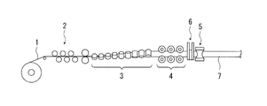
- FIG. 1 is a schematic view showing an example of an electric resistance welded steel pipe manufacturing facility.
- FIG. 2 is a schematic view showing a forming process of a square steel pipe.
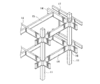
- FIG. 3 is a perspective view schematically showing an example of a building structure using the rectangular steel pipe of the present invention.
- FIG. 4 is a schematic view showing a cross section of a square steel pipe.
- the square steel pipe of the present invention is as follows.
- the composition of components is% by mass, C: 0.07 to 0.20%, Si: 1.0% or less, Mn: 0.5 to 2.0%, P: 0.030% or less, S: 0.0. It contains 015% or less, Al: 0.01 to 0.06%, N: 0.006% or less, and the balance is Fe and unavoidable impurities.
- the steel structure at a 1/4 depth position (hereinafter referred to as 1/4 t position) of the plate thickness t from the outer surface of this rectangular steel pipe has a ratio of the total area ratio of bainite and pearlite to the area ratio of ferrite is 2 The ratio of the area ratio of bainite to the area ratio of pearlite is 5.0 to 20.0.
- the flat plate portion of the square steel plate has YS of 350 MPa or more and TS of 520 MPa or more, the ratio of YS of the flat plate portion to the corner portion is 0.80 or more and 0.90 or less, and the ratio of TS of the flat plate portion to the corner portion is It is 0.90 or more and 1.00 or less, the Charpy absorbed energy at ⁇ 40° C. at the plate thickness 1 ⁇ 4t position of the flat plate portion is 100 J or more, and the R of the corner portion is (2.3 ⁇ t) or more (2. 9 ⁇ t) or less.
- C 0.07 to 0.20%
- C is an element that contributes to the formation of pearlite, which is one of the steel structures of the present invention described later, while increasing the strength of the steel plate and the square steel pipe by solid solution strengthening.
- C needs to be contained at 0.07% or more.
- C is 0.07 to 0.20%.
- C is preferably 0.09% or more, more preferably 0.10% or more. Further, C is preferably 0.18% or less, more preferably 0.17% or less.
- Si 1.0% or less
- Si is an element that contributes to the strength increase of steel plates and square steel pipes by solid solution strengthening.
- Si is preferably contained in an amount of more than 0.01%. However, if Si is contained in excess of 1.0%, the toughness decreases. Therefore, Si is set to 1.0% or less.
- Si is preferably 0.8% or less, and more preferably 0.6% or less. It is more preferably 0.03% or more.
- Mn 0.5-2.0%
- Mn is an element that increases the strength of steel plates and rectangular steel pipes through solid solution strengthening, and it is necessary to contain 0.5% or more of Mn in order to secure the desired strength of steel plates and rectangular steel pipes. If the Mn content is less than 0.5%, the ferrite transformation start temperature rises, the structure becomes excessively coarse, and the toughness decreases. On the other hand, if Mn is contained in excess of 2.0%, the hardness of the central segregation portion increases, which may cause cracking during welding of the rectangular steel pipe in the field. Therefore, Mn is set to 0.5 to 2.0%. Mn is preferably 1.8% or less, more preferably 1.6% or less. Mn is preferably 0.6% or more, more preferably 0.7% or more.
- P 0.030% or less
- P is an element that segregates at the ferrite grain boundaries to reduce the toughness of the steel plate and the square steel pipe.
- P is preferably 0.002% or more.
- the content of P is allowable up to 0.030%. Therefore, P is 0.030% or less.
- P is preferably 0.025% or less.
- P is more preferably 0.020% or less.
- S 0.015% or less S exists as sulfide in steel, and exists mainly as MnS within the range of the composition of the present invention. MnS is thinly drawn in the hot rolling process and adversely affects the ductility and toughness of steel plates and rectangular steel pipes. Therefore, in the present invention, it is desirable to reduce MnS as much as possible. However, excessive reduction leads to a high refining cost, so S is preferably 0.0002% or more. In addition, the content of S is allowable up to 0.015%. Therefore, S is set to 0.015% or less. S is preferably 0.010% or less, more preferably 0.008% or less.
- Al 0.01 to 0.06%
- Al is an element that acts as a deoxidizing agent and has the action of fixing N as AlN.
- Al needs to be contained by 0.01% or more.
- Al is less than 0.01%, the deoxidizing power becomes insufficient when Si is not added, the amount of oxide inclusions increases, and the cleanliness of the steel sheet decreases.
- Al is set to 0.01 to 0.06%.
- Al is preferably 0.02% or more. Further, Al is preferably 0.05% or less.
- N 0.006% or less
- N is an element having an action of firmly fixing the motion of dislocations to reduce the toughness of the steel plate and the rectangular steel pipe.
- N is set to 0.006% or less.
- N is preferably 0.005% or less.
- N is preferably 0.001% or more from the viewpoint of manufacturing cost.
- the balance is Fe and inevitable impurities.
- O oxygen
- Nb 0.05% or less
- Ti 0.05% or less
- V 0.10% or less
- Nb, Ti, and V are all fine carbides in steel.
- Nb 0.05% or less
- Ti 0.05% or less
- V 0.10% or less
- Nb 0.05% or less
- Ti 0.05% or less
- V 0.10% or less
- Nb 0.04% or less
- Ti 0.04% or less
- V 0.08% or less.
- Nb 0.001% or more
- V: 0.001% or more are preferable
- the total content is preferably 0.2% or less, and more preferably 0.005% or more.
- B 0.008% or less
- B is an element having a function of delaying the ferrite transformation in the cooling process, promoting the formation of low-temperature transformed ferrite, and increasing the strength of the steel sheet and the square steel pipe.
- the content of B leads to an increase in the yield ratio of the steel plate, that is, the yield ratio of the rectangular steel pipe. Therefore, in the present invention, B can be contained if necessary for the purpose of adjusting the strength, as long as the yield ratio of the rectangular steel pipe is 90% or less.
- B is contained, it is preferably 0.008% or less.
- B is more preferably 0.0015% or less, still more preferably 0.0008% or less.
- B is preferably 0.0001% or more, more preferably 0.0003% or more.
- Cr 0.01 to 1.0%, Mo: 0.01 to 1.0%, Cu: 0.01 to 0.50%, Ni: 0.01 to 0.30%, Ca: 0.001 to
- 0.010% Cr: 0.01-1.0% Cr is an element that increases the hardenability and thereby increases the strength of the steel plate and the rectangular steel pipe, and can be contained if necessary.
- Cr is contained to obtain such an effect, it is preferable to contain 0.01% or more of Cr.
- Cr is if Cr is contained in excess of 1.0%, the toughness and weldability may be deteriorated. Therefore, when Cr is contained, it is preferably 1.0% or less.
- Cr is more preferably 0.02% or more, and even more preferably 0.8% or less.
- Mo 0.01-1.0%
- Mo is an element that enhances the hardenability to increase the strength of the steel plate and the rectangular steel pipe, and can be contained if necessary. When Mo is contained to obtain such an effect, it is preferable to contain 0.01% or more of Mo. On the other hand, if Mo is contained in excess of 1.0%, the toughness may be lowered, so when Mo is contained, it is preferably 1.0% or less. Mo is more preferably 0.02% or more, and even more preferably 0.8% or less.
- Cu 0.01 to 0.50%
- Cu is an element that increases the strength of the steel plate and the rectangular steel pipe by solid solution strengthening, and can be contained if necessary.
- the content is preferably 0.50% or less.
- Cu is more preferably 0.02% or more, and further preferably 0.4% or less.
- Ni 0.01 to 0.30%
- Ni is an element that increases the strength of the steel plate and the rectangular steel pipe by solid solution strengthening, and can be contained if necessary. When Ni is contained to obtain such an effect, it is preferable to contain 0.01% or more of Ni. On the other hand, if Ni is contained in excess of 0.30%, the area ratio of the ferrite may be easily reduced. Therefore, when Ni is contained, it is preferably 0.30% or less. Ni is more preferably 0.02% or more, and further preferably 0.2% or less.
- Ca 0.001 to 0.010%
- Ca is an element that contributes to improving the toughness of steel by spheroidizing sulfides such as MnS that are thinly stretched in the hot rolling step, and can be contained if necessary.
- the Ca content exceeds 0.010%, Ca oxide clusters are formed in the steel and the toughness may deteriorate. Therefore, when Ca is contained, the Ca content is preferably 0.001 to 0.010%.
- Ca is more preferably 0.0015% or more, and more preferably 0.0050% or less.
- the steel structure at the 1/4 t position in the rectangular steel pipe of the present invention mainly has ferrite, pearlite and bainite, and the ratio of each structure is that of bainite (B) and pearlite (P) with respect to the area ratio of ferrite (F).
- the total area ratio ((B+P)/F) is 2.0 or more and 20.0 or less, and the ratio of bainite area ratio (B/P) to the pearlite area ratio is 5.0 or more and 20.0 or less. Is.
- Ratio of the total area ratio of bainite and pearlite to the area ratio of ferrite 2.0 or more and 20.0 or less If the total ratio of the area ratio of bainite and pearlite to the area ratio of ferrite is less than 2.0, bainite that bears strength The desired strength cannot be obtained because of insufficient pearlite and pearlite. On the other hand, when the ratio of the total area ratio of bainite and pearlite to the area ratio of ferrite exceeds 20.0, strain tends to be dispersed in bainite and pearlite when manufacturing a rectangular steel pipe by cold roll forming, and work hardening occurs. Easier to do. As a result, it is not possible to obtain a rectangular steel pipe having a small difference in strength between the corner portion and the flat plate portion.
- Ratio of area ratio of bainite to area ratio of pearlite 5.0 or more and 20.0 or less If the ratio of area ratio of bainite to area ratio of pearlite is less than 5.0, pearlite becomes excessive and toughness decreases. On the other hand, when the ratio of the area ratio of bainite to the area ratio of pearlite exceeds 20.0, strain is likely to be dispersed in bainite and work hardening is likely to occur. As a result, it is not possible to obtain a rectangular steel pipe having a small difference in strength between the corner portion and the flat plate portion.
- a square steel pipe manufactured by roll forming using a steel plate has the same steel structure at the 1/4t position at both the corner portion and the flat plate portion, so the flat plate portion at the 1/4t position.
- the measurement may be performed at any of the 1/4t positions of the corner.
- the steel structure at the 1/4t position of the flat plate portion is defined.
- the "steel structure at the 1/4t position" means that the above-mentioned steel structure exists in any of the ranges from the 3/16t position to the 5/16t position described above.
- the above steel structure is observed by the following method, and the type and area ratio (%) of the structure are obtained.
- the test piece for microscopic observation is taken from a rectangular steel pipe, polished so that the cross section (L cross section) in the rolling direction becomes the observation surface, and subjected to nital corrosion to produce.
- the structure was observed by using an optical microscope (magnification: 500 times) or a scanning electron microscope (SEM) with the structure at the 1/4 t thickness of the structure as the center of observation from the surface of the test piece for structure observation (that is, the outer surface of the rectangular steel pipe). , Magnification: 500 times), and the steel structure is observed and imaged.
- t indicates the thickness of the steel plate (plate thickness).
- the type of structure is specified using an image analysis device (image analysis software: Photoshop, made by Adobe), and the area ratio of each structure (ferrite, pearlite, bainite) is calculated.
- image analysis software Photoshop, made by Adobe
- the area ratio of each tissue was obtained by observing in five or more visual fields and averaging the values obtained in each visual field.
- FIG. 1 is a schematic view showing an example of an electric resistance welded steel pipe manufacturing facility.
- FIG. 2 is a schematic view showing a forming process of a square steel pipe.
- the method for manufacturing a rectangular steel pipe of the present invention is to subject a steel plate to a pipe forming step to form a rectangular steel pipe.
- the steel plate is cold-rolled and the cylindrical end surface is welded.
- the round steel pipe is further cold-shaped into square shape by rolls arranged vertically and horizontally. To form a square steel pipe having a corner and a flat plate.
- a steel strip 1 which is a raw material of an electric resistance welded steel pipe is subjected to an entrance side correction by a leveler 2 and then intermediately formed by a cage roll group 3 made up of a plurality of rolls to form an open pipe.
- the fin-pass roll group 4 including a plurality of rolls is finish-molded.
- the width end of the steel strip 1 is resistance-welded by the welding machine 6 while being pressed against the squeeze roll 5 to form the cylindrical electric resistance welded steel pipe 7.
- the facility for manufacturing the electric resistance welded steel pipe 7 is not limited to the pipe making process as shown in FIG.
- the electric resistance welded steel pipe 7 is reduced in diameter by a sizing roll group (sizing stand) 8 made up of a plurality of rolls while remaining in a cylindrical shape, and the longitudinal/lateral diameter ratio is 0.99 or more.
- the cylindrical shape is 01 or less.
- a square forming roll group (square forming stand) 9 composed of a plurality of rolls, the square steel pipe 10 is sequentially formed into a shape such as R1, R2, and R3.
- the number of stands of the sizing roll group 8 and the corner forming roll group 9 is not particularly limited.
- the present invention it is important to set the ratio of longitudinal diameter/horizontal diameter to 0.99 or more and 1.01 or less for the following reasons.
- a steel pipe is manufactured by roll forming, in the process, non-uniform strain is often applied in the circumferential direction for the purpose of suppressing springback.
- the cylindrical cross-section which is the previous stage, does not necessarily need to be a perfect circle. Therefore, even if it is called a cylindrical shape, it is not necessarily a perfect circle at the stage of manufacturing the rectangular steel pipe, and as a result, the obtained rectangular steel pipe cannot reduce the difference in characteristics between the flat plate portion and the corner portion. From this, in the present invention, in order to reduce the characteristic difference between the flat plate portion and the corner portion, the shape is formed into a cylindrical shape having a longitudinal diameter/horizontal diameter ratio of 0.99 or more and 1.01 or less in the previous step. Is mandatory.
- the plastic strain at the corners becomes too large compared to the flat plate unless it is formed into a cylindrical shape with a ratio of longitudinal diameter/lateral diameter of 0.99 or more and 1.01 or less.
- the ratio of YS of the flat plate portion to the corner portion is less than 0.80
- the ratio of TS of the flat plate portion to the corner portion is less than 0.90. Since the plastic strain of the corner portion is larger than that of the flat plate portion, the YS ratio of the flat plate portion to the corner portion is 0.90 or less, and the TS ratio of the flat plate portion to the corner portion is 1.00 or less. It is natural.
- the YS of the flat plate portion targeted in the present invention is 350 MPa or more
- the TS is 520 MPa or more
- the ratio of the YS of the flat plate portion to the corner portion is 0.80 to 0.90
- the TS of the flat plate portion to the corner portion is In order to set the ratio to 0.90 or more and 1.00 or less, it is formed into a cylindrical shape having a longitudinal diameter/horizontal diameter ratio of 0.99 or more and 1.01 or less.
- R of the corners is (2 It can be set to 0.3 ⁇ t) or more and (2.9 ⁇ t) or less (where t is the plate thickness).
- the R of the corner portion is (2.3 ⁇ t) or more and (2.9 ⁇ t) or less (where t is the plate thickness) so that the strength difference between the corner portion and the flat plate portion is reduced.
- YS of the flat plate portion is 350 MPa or more
- TS is 520 MPa or more
- the ratio of YS of the flat plate portion to the corner portion is 0.80 or more and 0.90 or less
- the TS of the flat plate portion to the corner portion is TS.
- the Charpy absorbed energy at ⁇ 40° C. of the flat plate portion is 100 J or more
- the R of the corner portion is (2.3 ⁇ t) or more and (2.9 ⁇ t) or less.
- the square steel pipe of the present invention preferably uses, as its material, a steel sheet (hot rolled steel sheet) obtained by sequentially performing the hot rolling step, the cooling step, and the winding step described below. You can In the present invention, this steel plate may be subjected to the above-described pipe forming step to form a square steel pipe.
- a steel sheet hot rolled steel sheet obtained by sequentially performing the hot rolling step, the cooling step, and the winding step described below.
- a method for producing a steel sheet suitable as a material for a rectangular steel pipe of the present invention includes, for example, a steel material having the above-described composition, under the conditions described below, in a hot rolling step (hereinafter referred to as a hot rolling step), A steel plate (hot rolled steel plate) can be obtained by performing the cooling process and the winding process in this order.
- the steel material is heated with respect to the heated steel material.
- rough rolling end temperature 1000 to 800°C
- finish rolling start A hot rolling process is carried out at a temperature of 1000 to 800° C. and a finish rolling finish temperature of 900 to 750° C. to obtain a hot rolled sheet.
- the hot-rolled sheet after the hot rolling step has at least one 0.2-second or more-less than 3.0-second cooling period for 10 seconds from the start of cooling, and the average cooling rate at the sheet thickness center temperature of the hot-rolled sheet. : 4 to 25° C./s, cooling stop temperature: 580° C. or less. Then, the hot rolled sheet after the cooling step is wound at a coiling temperature of 580° C. or lower, and then subjected to a coiling step of allowing it to cool to obtain a steel sheet (hot rolled steel sheet).
- the temperature (° C.) is the surface temperature of a steel material, a sheet bar, a hot rolled plate, a steel plate or the like, unless otherwise specified. These surface temperatures can be measured with a radiation thermometer or the like. Unless otherwise specified, the average cooling rate (°C/s) is ((temperature before cooling (°C)-temperature after cooling (°C))/cooling time (s)). The value obtained by.
- the melting method of the steel material (steel slab) having the above-mentioned composition is not particularly limited, and it can be melted using a known melting method such as a converter, an electric furnace and a vacuum melting furnace.
- the casting method is also not particularly limited, and it can be manufactured to a desired size by a known casting method such as a continuous casting method. It should be noted that there is no problem even if the ingot-bulk rolling method is applied instead of the continuous casting method.
- the molten steel may be further subjected to secondary refining such as ladle refining.
- a hot rolling process is applied to the obtained steel material (steel slab).
- the steel material is heated to a heating temperature of 1100-1300°C. Then, the heated steel material is roughly rolled. At this time, after the steel material is extracted from the heating furnace, it is allowed to stand for 30 seconds or more in the state where the center temperature of the steel material thickness is 1000°C or more until the rough rolling ends.
- rough rolling is performed at a rough rolling end temperature of 1000 to 800°C. After that, finish rolling with a finish rolling start temperature of 1000 to 800° C. and a finish rolling end temperature of 900 to 750° C. is performed to obtain a hot rolled sheet.
- the temperature at the thickness center of the steel material in the hot rolling process is calculated by calculating the temperature distribution in the steel material cross section by heat transfer analysis.
- Heating temperature 1100 to 1300°C If the heating temperature of the steel material is less than 1100° C., the deformation resistance of the material to be rolled becomes too large, resulting in insufficient load capacity and rolling torque in the rough rolling mill and finish rolling mill, making rolling difficult. On the other hand, if the heating temperature exceeds 1300° C., the austenite crystal grains become coarse, and even if the working and recrystallization of the austenite grains are repeated in rough rolling and finish rolling, it becomes difficult to make them finer, which is desirable in hot rolled steel sheets. It becomes difficult to secure the toughness of Therefore, the heating temperature of the steel material is set to 1100 to 1300°C. The heating temperature is preferably 1280°C or lower. The heating temperature is preferably 1150° C. or higher.
- a temperature in the range of 1100°C or lower and the Ar3 transformation point or higher may be selected as the heating temperature.
- the heated steel material is then roughly rolled to form a sheet bar, etc.
- the number of the above-mentioned leaving times exceeds 5
- the scale growth becomes excessive
- the ratio of the total area ratio of bainite and pearlite to the area ratio of ferrite exceeds 20.0
- the area ratio of pearlite to the area ratio of pearlite exceeds 20.0.
- the number of the above-mentioned leaving time is preferably twice or more. It is preferably 4 times or less.
- Rough rolling end temperature 1000-800°C
- the austenite grains of the heated steel material are processed and recrystallized by rough rolling to be refined.
- the rough rolling finish temperature is lower than 800° C.
- insufficient load capacity and rolling torque of the rough rolling machine are likely to occur.
- the rough rolling end temperature exceeds 1000° C. and reaches a high temperature, the austenite grains are coarsened, and the toughness of the steel sheet and the square steel pipe is likely to be reduced.
- the rough rolling end temperature is preferably 820° C. or higher, and more preferably 840° C. or higher.
- the rough rolling finish temperature is preferably 980° C. or lower, and more preferably 950° C. or lower.
- the rough rolling finish temperature can be achieved by adjusting the heating temperature of the steel material, the cooling conditions during the rough rolling, the retention between the rough rolling passes, the steel material thickness, and the like.
- the thickness of the material to be rolled (thickness of the sheet bar, etc.) at the stage of finishing the rough rolling is not particularly limited, and the product sheet (hot rolled steel sheet) having the desired product thickness by finish rolling should be used. I wish I could.
- the product thickness is preferably about 12 to 28 mm.
- the material to be rolled is subjected to finish rolling with, for example, a tandem rolling mill to form a hot rolled sheet.
- Finish rolling start temperature 1000-800°C
- finish rolling entry side temperature the processing strain introduced by the rolling process tends to remain, and it is easy to achieve the refinement of ⁇ grains.
- finish rolling start temperature is less than 800° C.
- the temperature near the surface of the steel sheet in the finish rolling mill becomes the Ar3 transformation point or lower, and the risk of ferrite formation increases.
- the ferrite generated before and during finish rolling becomes ferrite grains elongated in the rolling direction by the subsequent finish rolling, which causes a decrease in toughness.
- finish rolling start temperature exceeds 1000° C.
- the finish rolling start temperature is set to 800 to 1000°C.
- the finish rolling start temperature is preferably 825 to 975°C.
- Finish rolling finish temperature 900-750°C
- finish rolling end temperature (finish rolling exit side temperature) exceeds 900° C. and reaches a high temperature, the processing strain added during finish rolling is insufficient, the refinement of ⁇ grains is not achieved, and the toughness of the steel plate and the square steel pipe is reduced. It tends to decrease.
- finish rolling finish temperature is lower than 750° C., the temperature in the vicinity of the steel sheet surface in the finish rolling mill becomes the Ar3 transformation point or lower, ferrite grains elongated in the rolling direction are formed, and the ferrite grains become mixed grains. This increases the risk of reduced toughness. Therefore, the finish rolling finish temperature is set to 900 to 750°C.
- the finish rolling end temperature is preferably 850° C. or lower. It is preferably 770° C. or higher.
- the hot rolled sheet obtained in the hot rolling step is subjected to a cooling step.
- Number of times of cooling for 0.2 s or more and less than 3.0 s in 10 s from the start of cooling 10 seconds (between 10 s) after cooling of the hot rolled sheet obtained in the hot rolling step is started.
- the initial cooling In the initial cooling of the cooling step, cooling is performed once or more for 0.2 s or more and less than 3.0 s. This is performed to suppress the formation of martensitic structure on the front and back surfaces of the steel sheet.
- the initial cooling if cooling is not provided or cooling is less than 0.2 s, a martensitic structure is generated, and the toughness of the steel plate and the square steel pipe decreases.
- one cooling time performed during the initial cooling in the cooling step is set to 0.2 s or more and less than 3.0 s.
- the one-time cooling time is preferably 0.4 s or more, and preferably 2.0 s or less.
- the number of times of cooling during the initial cooling needs to be once or more.
- the number of times of cooling may be appropriately set depending on the arrangement of the cooling equipment, the cooling stop temperature, and the like.
- the cooling is naturally cooled.
- the upper limit of the number of times of cooling is not particularly limited, but from the viewpoint of productivity, it is preferably 10 times or less.
- the number of times of cooling is set to a plurality of times, it may be appropriately set by, for example, intermittent injection by stopping the injection of water from a nozzle in a partial section of a water cooling nozzle described later.
- the hot rolled sheet obtained by finish rolling is cooled from the start of cooling to the stop of cooling (end of cooling). Cooling is performed so that the average cooling rate at the plate thickness center temperature is 4 to 25° C./s and the cooling stop temperature is 580° C. or less.
- the cooling performed in the cooling step is performed by water cooling (water cooling) such as water column cooling, spray cooling, mist cooling, or the like, or gas jet cooling that injects cooling gas, for example, water is injected from a nozzle.
- water cooling water cooling
- the average cooling rate of the thickness center of the hot-rolled sheet is less than 4°C/s, the ratio of the area ratio of bainite to the area ratio of pearlite is less than 5.0, and the toughness deteriorates.
- the average cooling rate exceeds 25° C./s, the ratio of the area ratio of bainite to the area ratio of pearlite exceeds 20.0, strain is likely to be dispersed in bainite, and work hardening is likely to occur. As a result, it becomes impossible to obtain a rectangular steel pipe having a small strength difference between the corner portion and the flat plate portion. Therefore, the average cooling rate at the center of the thickness of the hot rolled sheet is set to 4 to 25°C/s.
- the average cooling rate at the plate thickness center of the hot-rolled sheet is preferably 5°C/s or more, and preferably 15°C/s or less.
- the average cooling rate of the thickness center of the hot rolled sheet is ((Temperature of thickness center at cooling start (°C)-Temperature of thickness center at cooling stop (°C))/Cooling time (s)) Required by.
- the temperature at the thickness center of the hot rolled sheet is obtained by calculating the temperature distribution in the section of the sheet by heat transfer analysis.
- the cooling stop temperature exceeds 580°C, the ratio of the area ratio of bainite to the area ratio of pearlite is less than 5.0, and the toughness deteriorates.
- the cooling stop temperature is preferably 560° C. or lower.
- the average cooling rate in the temperature range of 750 to 650°C of the surface temperature of the hot rolled sheet is 20°C/s or more. If the average cooling rate in this temperature range is less than 20° C./s, the ratio of the area ratio of bainite to the area ratio of pearlite may be less than 5.0.
- the average cooling rate in the temperature range of 750 to 650° C. at the surface temperature of the hot rolled sheet is preferably 80° C./s or less. If the average cooling rate in this temperature range exceeds 80° C./s, the ratio of the area ratio of bainite to the area ratio of pearlite may exceed 20.0. Further, in order to control the production amount of pearlite and bainite, it is preferable to start the cooling step immediately (within 5 seconds) after finishing rolling.
- the hot rolled sheet after cooling is subjected to a winding process to obtain a steel sheet (hot rolled sheet).
- Winding temperature 580°C or lower
- a step of winding the hot rolled sheet at a winding temperature: 580°C or lower and then allowing it to cool is performed. If the coiling temperature exceeds 580° C., ferrite transformation and pearlite transformation proceed after coiling, the proportion of pearlite becomes excessive, and the toughness of the steel sheet and the square steel pipe decreases. Therefore, the winding temperature is set to 580°C or lower.
- the winding temperature is preferably 550°C or lower.
- the winding temperature is preferably 400° C. or higher.
- the steel plate after the winding process (hot rolled steel plate) is subjected to the above-mentioned pipe forming process to obtain a square steel pipe.
- FIG. 3 is a perspective view schematically showing a building structure according to the embodiment of the present invention.
- a plurality of rectangular steel pipes 11 of the present invention are erected and used as a pillar material.
- a plurality of girders 14 made of a steel material such as H-section steel are installed between adjacent rectangular steel pipes 11.
- a plurality of small beams 15 made of a steel material such as H-shaped steel is installed between the adjacent large beams 14.
- the large beam 14 made of a steel material such as an H-shaped steel is installed between the adjacent rectangular steel pipes 11.
- a stud 17 is provided as needed for mounting a wall or the like.
- the building structure of the present invention uses the square steel pipe 11 of the present invention in which the strength difference between the corner portion and the flat plate portion is small, it is easy to select a welding material for welding the square steel pipe 11 and the diaphragm 16, such as undermatch.
- the strength difference with the welding material is unlikely to occur.
- the undermatch hardly occurs, troubles such as breakage at the welded portion can be suppressed.
- the angle R (R of the corner portion) of the rectangular steel pipe 11 is controlled to an appropriate size, it is easy to combine with another structural member having a right angle cross section.
- the angle R of the rectangular steel pipe 11 is controlled to an appropriate size, it is possible to withstand a larger external force, and the earthquake resistance and the like are improved.
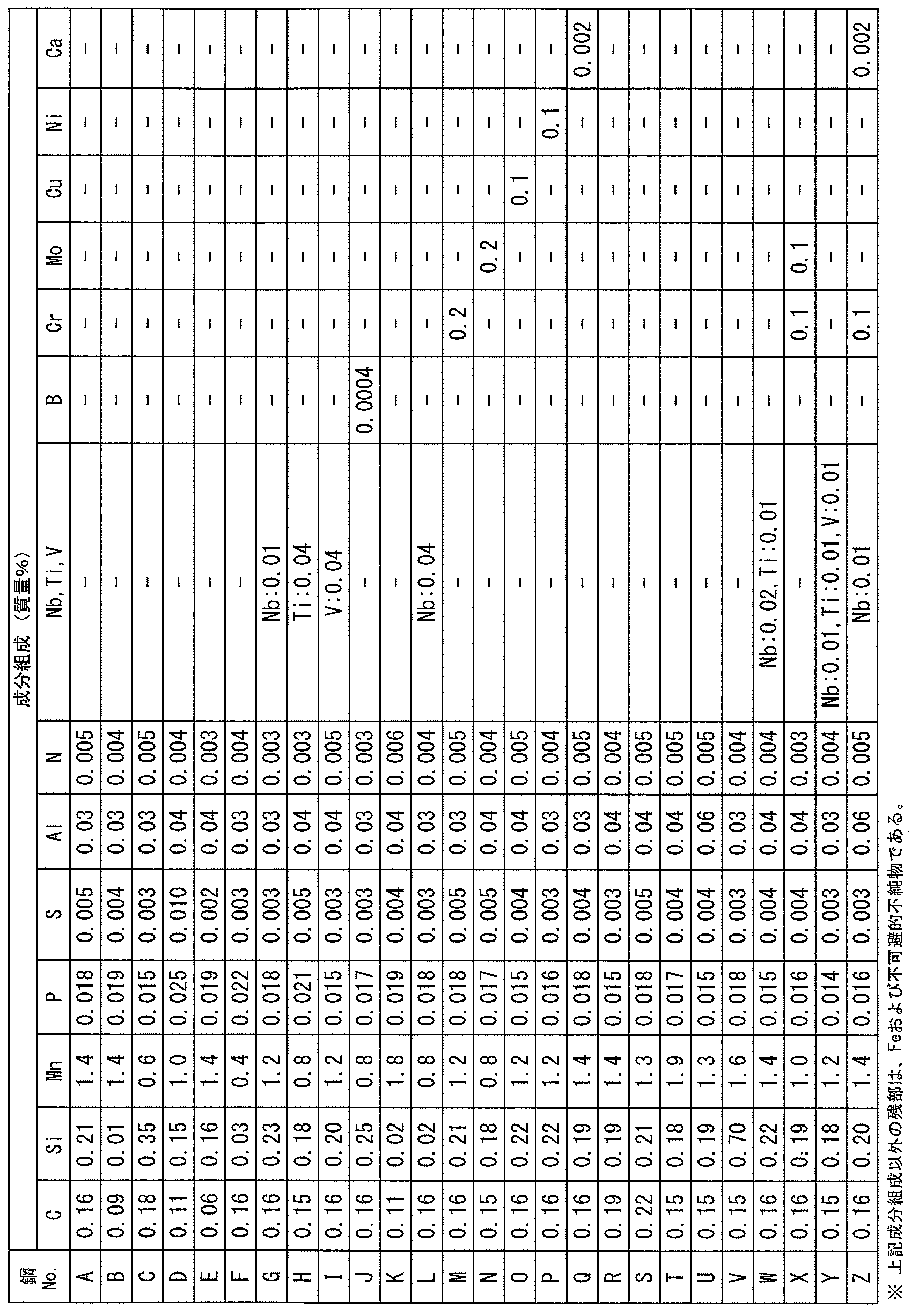
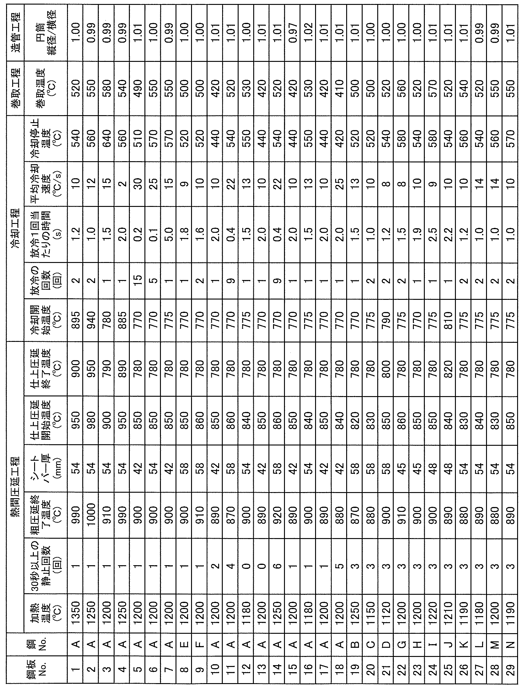
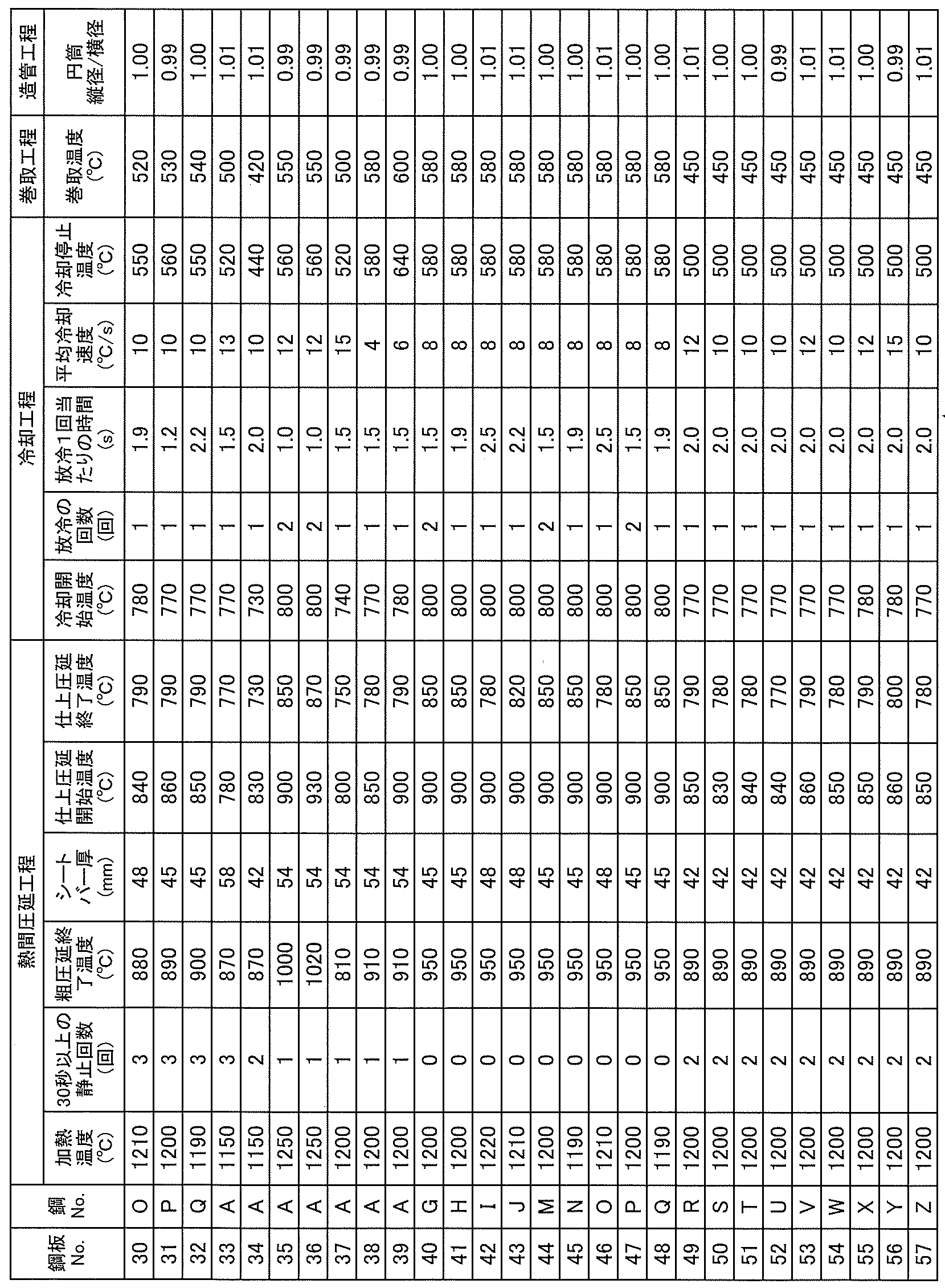
- Molten steel was smelted in a converter and made into a slab (steel material: wall thickness 250 mm) with the composition shown in Table 1 by the continuous casting method. These slabs (steel materials) are heated to the heating temperature under the conditions shown in Table 2-1 and Table 2-2, then subjected to a hot rolling step, a cooling step, and a winding step, and then allowed to cool and plate. Thickness: 16-28 mm steel plate (hot rolled steel plate).
- the cooling step was started immediately (within 5 seconds) after finishing rolling. Cooling was performed by water cooling.
- the cooling during the initial cooling was performed by providing a cooling section in which water cooling is not performed during the initial cooling for 10 seconds from the start of cooling.
- a cold rolled roll was formed into a round steel pipe under the conditions shown in Table 2-1 and Table 2-2, and then a cold rolled square pipe was formed (400 to 550 mm square). ).
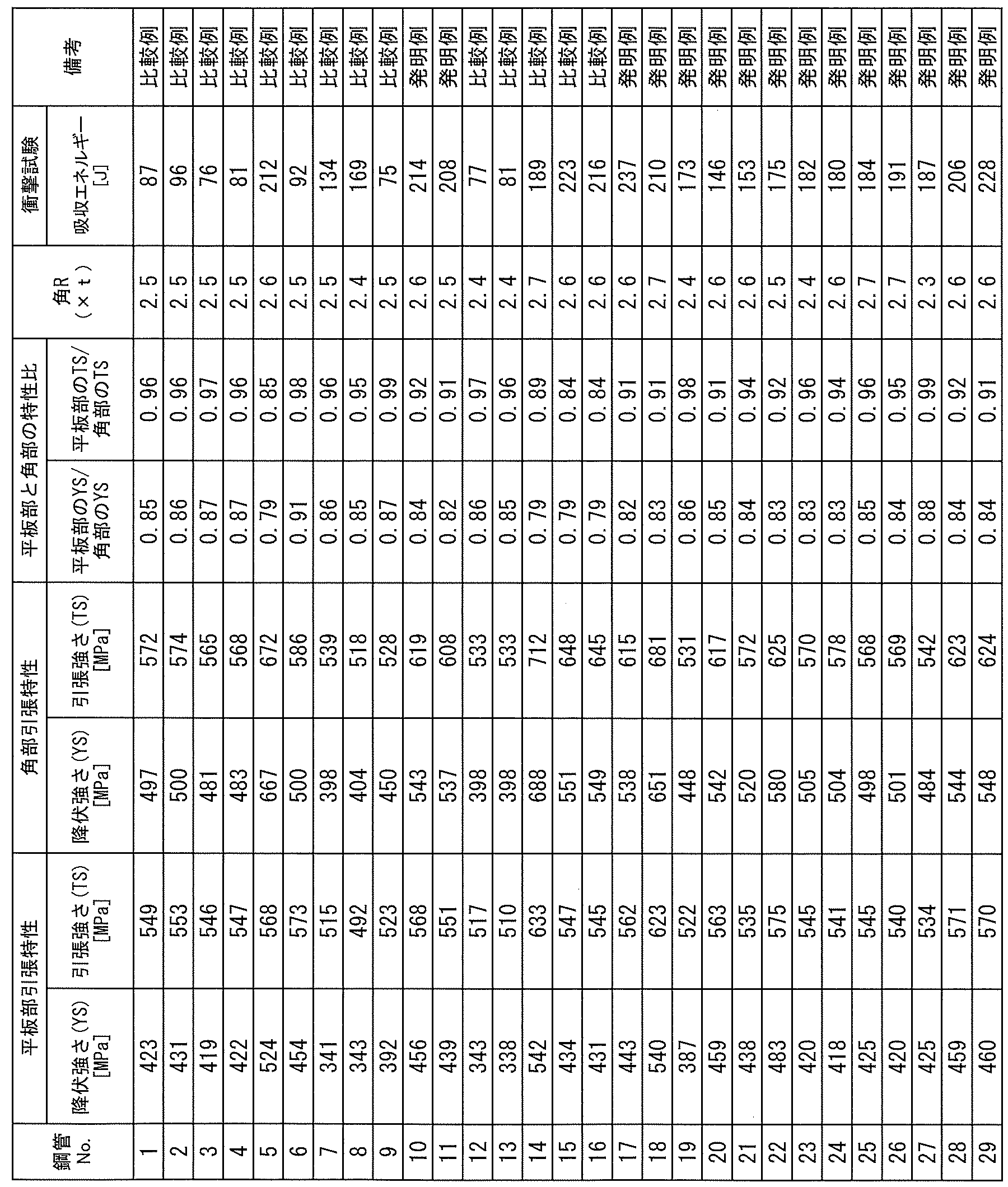
- test pieces were sampled from the obtained rectangular steel pipes, and the structure was observed, the tensile test, the Charpy impact test, and the R of the corners were measured.
- the structure was observed and measured by the above method.
- the tensile test, the Charpy impact test, and the R measurement method at the corners were as follows. (1) Rectangular steel pipe tensile test JIS 5 tensile test pieces were sampled from the flat plate and the corners of the obtained rectangular steel pipe such that the tensile direction was the pipe longitudinal direction. Then, a tensile test was carried out in accordance with the regulations of JIS Z 2241 (2011), and the yield strength YS and the tensile strength TS were measured.
- the radius of curvature of the corner is the curvature at the intersection of the line (L) that forms an angle of 45° with the adjacent side starting from the center of the pipe and the outside of the corner (outer surface side of the corner).
- the radius of curvature of the corner is such that the center angle is 65°, which is centered on the above L and is defined by the line drawn toward the connection point (A, A′) between the flat part and the arc part of the rectangular steel pipe.
- the radius of curvature can be calculated by using the sine theorem from the measurement result of the distance relationship of three points (intersection points outside the corners and two points that are the connection points of the flat portion and the arc portion).
- a calculation method and a method of measuring the radius of curvature from a radial gauge that matches well with the corners in the three points but the method is not limited to this.
- a radial gauge was used to measure the radius of curvature of the corners.
- the angle R is an average value of 10 cross sections perpendicular to the tube axis direction as described above.
- the characteristics of the present invention (YS of the flat plate portion was 350 MPa or more, TS was 520 MPa or more, the ratio of YS of the flat plate portion to the corner portion was 0.80 or more and 0.90 or less, the flat plate Ratio of the TS of the corner portion to the corner portion is 0.90 or more and 1.00 or less, the Charpy absorbed energy at -40° C. of the flat plate portion is 100 J or more, and the R of the corner portion is (2.3 ⁇ t) or more (2.9 ⁇ t) or less) (where t is the plate thickness).
- the characteristics of the present invention could not be obtained in the comparative examples outside the scope of the present invention.
Landscapes
- Chemical & Material Sciences (AREA)
- Engineering & Computer Science (AREA)
- Mechanical Engineering (AREA)
- Organic Chemistry (AREA)
- Materials Engineering (AREA)
- Metallurgy (AREA)
- Architecture (AREA)
- Physics & Mathematics (AREA)
- Civil Engineering (AREA)
- Structural Engineering (AREA)
- Thermal Sciences (AREA)
- Crystallography & Structural Chemistry (AREA)
- Electromagnetism (AREA)
- Manufacturing & Machinery (AREA)
- Heat Treatment Of Steel (AREA)
- Rod-Shaped Construction Members (AREA)
Abstract
Description
(A)鋼管の平坦部における降伏強度:355MPa以上、引張強度:520MPa以上である、
(B)前記平坦部のミクロ組織において、ベイナイト組織の面積分率:40%以上である、
(C)鋼管の角部における表層部がビッカース硬さHv:350以下、引張試験での伸び:10%以上、0℃のシャルピー吸収エネルギーvE0:70J以上である。
[1] 平板部と角部を有する角形鋼管であって、
成分組成は、質量%で、
C:0.07~0.20%、
Si:1.0%以下、
Mn:0.5~2.0%、
P:0.030%以下、
S:0.015%以下、
Al:0.01~0.06%、
N:0.006%以下
を含有し、残部がFeおよび不可避的不純物からなり、
鋼管の外表面から板厚tの1/4t位置における鋼組織は、フェライトの面積率に対するベイナイトとパーライトの面積率の合計の割合が2.0以上20.0以下で、かつパーライトの面積率に対するベイナイトの面積率の割合が5.0以上20.0以下であり、
前記平板部は、YSが350MPa以上、TSが520MPa以上であり、
前記角部に対する前記平板部のYSの比は0.80以上0.90以下、前記角部に対する前記平板部のTSの比は0.90以上1.00以下であり、
前記平板部の-40℃のシャルピー吸収エネルギーは100J以上であり、
前記角部のRは(2.3×t)以上(2.9×t)以下
である角形鋼管。
[2] 前記成分組成に加えてさらに、質量%で、下記A群~C群のうちから選ばれた1群または2群以上を含有する[1]に記載の角形鋼管。
記
A群:Nb:0.05%以下、Ti:0.05%以下、V:0.10%以下のうちから選ばれた1種または2種以上
B群:B:0.008%以下
C群:Cr:0.01~1.0%、Mo:0.01~1.0%、Cu:0.01~0.50%、Ni:0.01~0.30%、Ca:0.001~0.010%のうちから選ばれた1種または2種以上
[3] [1]または[2]に記載の角形鋼管の製造方法であって、
鋼板を冷間でロール成形して円筒状にした端面を溶接し、縦径/横径の比で0.99以上1.01以下の円筒状に成形した後、角状に成形する造管工程を施す角形鋼管の製造方法。
[4] [1]または[2]に記載の角形鋼管の製造方法であって、
鋼素材に、熱間圧延工程、冷却工程、巻取工程および造管工程をこの順に施して角形鋼管を製造するに際し、
前記鋼素材を加熱温度:1100~1300℃に加熱した後、
加熱炉から抽出後、粗圧延が終了するまでの間に、加熱された前記鋼素材に対して、板厚中心温度が1000℃以上の状態で30秒以上静止する回数を1回以上5回以下に制御した上で、粗圧延終了温度:1000~800℃、仕上圧延開始温度:1000~800℃、仕上圧延終了温度:900~750℃とする熱間圧延工程を施し、
次いで、冷却開始から10s間における0.2s以上3.0s未満の放冷を1回以上有し、板厚中心温度での平均冷却速度:4~25℃/s、冷却停止温度:580℃以下とする冷却工程を施し、
次いで、巻取温度:580℃以下で巻取る巻取工程を施して鋼板とし、
次いで、前記巻取工程後の鋼板を冷間でロール成形して円筒状にした端面を溶接し、縦径/横径の比で0.99以上1.01以下の円筒状に成形した後、角状に成形する造管工程を施す角形鋼管の製造方法。
[5] [1]または[2]に記載の角形鋼管を使用した建築構造物。
Cは、固溶強化により鋼板および角形鋼管の強度を増加させるとともに、後述する本発明の鋼組織の一つであるパーライトの形成に寄与する元素である。所望の強度、さらに所望の鋼板組織を確保するためには、Cは0.07%以上の含有を必要とする。一方、0.20%を超えるCの含有は、角形鋼管の現場での溶接時に熱影響によりマルテンサイト組織が生成し、溶接割れの原因となる懸念がある。このため、Cは0.07~0.20%とする。Cは、好ましくは0.09%以上であり、より好ましくは0.10%以上である。また、Cは、好ましくは0.18%以下であり、より好ましくは0.17%以下である。
Siは、固溶強化で鋼板および角形鋼管の強度増加に寄与する元素である。所望の鋼板および角形鋼管の強度を確保するためには、Siは0.01%を超えて含有することが望ましい。しかし、1.0%を超えてSiを含有すると、靱性が低下する。このため、Siは1.0%以下とする。なお、Siは、好ましくは0.8%以下であり、より好ましくは0.6%以下である。より好ましくは0.03%以上である。
Mnは、固溶強化を介して鋼板および角形鋼管の強度を増加させる元素であり、所望の鋼板および角形鋼管の強度を確保するために、0.5%以上のMnの含有を必要とする。Mnが0.5%未満の含有では、フェライト変態開始温度の上昇を招き、組織が過度に粗大化し、靱性が低下する。一方、2.0%を超えてMnを含有すると、中心偏析部の硬度が上昇し、角形鋼管の現場での溶接時の割れの原因となる懸念がある。このため、Mnは0.5~2.0%とする。Mnは、好ましくは1.8%以下であり、より好ましくは1.6%以下である。Mnは、好ましくは0.6%以上であり、より好ましくは0.7%以上である。
Pは、フェライト粒界に偏析して、鋼板および角形鋼管の靭性を低下させる作用を有する元素である。本発明では、不純物としてできるだけ低減することが望ましい。しかし、過度の低減は、精錬コストの高騰を招くため、Pは0.002%以上とすることが好ましい。なお、Pの含有は0.030%までは許容できる。このため、Pは0.030%以下とする。Pは、好ましくは0.025%以下である。Pは、より好ましくは0.020%以下である。
Sは、鋼中では硫化物として存在し、本発明の成分組成の範囲であれば、主としてMnSとして存在する。MnSは、熱間圧延工程で薄く延伸され、鋼板および角形鋼管の延性および靭性に悪影響を及ぼす。このため、本発明ではできるだけMnSを低減することが望ましい。しかし、過度の低減は、精錬コストの高騰を招くため、Sは0.0002%以上とすることが好ましい。なお、Sの含有は0.015%までは許容できる。このため、Sは0.015%以下とする。Sは、好ましくは0.010%以下であり、より好ましくは0.008%以下である。
Alは、脱酸剤として作用するとともに、AlNとしてNを固定する作用を有する元素である。このような効果を得るためには、Alは0.01%以上の含有を必要とする。Alは0.01%未満では、Si無添加の場合に脱酸力が不足し、酸化物系介在物が増加し、鋼板の清浄度が低下する。一方、0.06%を超えるAlの含有は、固溶Al量が増加し、角形鋼管の長手溶接時(すなわち、角形鋼管の製造における鋼管長手方向の電縫溶接時)、特に大気中での溶接の場合に、溶接部に酸化物を形成させる危険性が高くなり、角形鋼管溶接部の靭性が低下する。このため、Alは0.01~0.06%にする。Alは、好ましくは0.02%以上である。また、Alは、好ましくは0.05%以下である。
Nは、転位の運動を強固に固着することで鋼板および角形鋼管の靭性を低下させる作用を有する元素である。本発明では、Nは不純物としてできるだけ低減することが望ましく、0.006%までは許容できる。このため、Nは0.006%以下とする。Nは、好ましくは0.005%以下である。本発明では特に規定しないが、製造コストの観点より、Nは0.001%以上とすることが好ましい。
Nb、Ti、Vはいずれも、鋼中で微細な炭化物、窒化物を形成し、析出強化を通じて鋼の強度向上に寄与する元素である。このような効果を得るために、Nb、Ti、Vを含有する場合は、それぞれ、Nb:0.05%以下、Ti:0.05%以下、V:0.10%以下とすることが好ましく、Nb:0.04%以下、Ti:0.04%以下、V:0.08%以下とすることがより好ましい。Nb、Ti、Vを含有する場合は、それぞれ、Nb:0.001%以上、Ti:0.001%以上、V:0.001%以上とすることが好ましく、Nb:0.003%以上、Ti:0.003%以上、V:0.003%以上とすることがより好ましい。
Bは、冷却過程のフェライト変態を遅延させ、低温変態フェライトの形成を促進し、鋼板および角形鋼管の強度を増加させる作用を有する元素である。Bの含有は、鋼板の降伏比、すなわち角形鋼管の降伏比の増加に繋がる。このため、本発明では、角形鋼管の降伏比が90%以下となるような範囲であれば、強度を調整する目的で必要に応じてBを含有できる。Bを含有する場合は、0.008%以下とすることが好ましい。Bは、より好ましくは0.0015%以下であり、さらに好ましくは0.0008%以下である。Bは、好ましくは0.0001%以上であり、より好ましくは0.0003%以上である。
Cr:0.01~1.0%
Crは、焼入れ性を高めることで、鋼板および角形鋼管の強度を上昇させる元素であり、必要に応じて含有することができる。そのような効果を得るためにCrを含有する場合は、0.01%以上のCrを含有することが好ましい。一方、1.0%を超えてCrを含有すると靱性や溶接性を低下させるおそれがあるので、Crを含有する場合は1.0%以下とすることが好ましい。Crは、より好ましくは0.02%以上であり、より好ましくは0.8%以下である。
Moは、焼入れ性を高めることで、鋼板および角形鋼管の強度を上昇させる元素であり、必要に応じて含有することができる。そのような効果を得るためにMoを含有する場合は、0.01%以上のMoを含有することが好ましい。一方、1.0%を超えてMoを含有すると靱性を低下させるおそれがあるので、Moを含有する場合は1.0%以下とすることが好ましい。Moは、より好ましくは0.02%以上であり、より好ましくは0.8%以下である。
Cuは、固溶強化により鋼板および角形鋼管の強度を上昇させる元素であり、必要に応じて含有することができる。そのような効果を得るためにCuを含有する場合は、0.01%以上のCuを含有することが好ましい。一方、0.50%を超えてCuを含有すると靱性を低下させるおそれがあるので、Cuを含有する場合は0.50%以下とすることが好ましい。Cuは、より好ましくは0.02%以上であり、より好ましくは0.4%以下である。
Niは、固溶強化により鋼板および角形鋼管の強度を上昇させる元素であり、必要に応じて含有することができる。そのような効果を得るためにNiを含有する場合は、0.01%以上のNiを含有することが好ましい。一方、0.30%を超えてNiを含有するとフェライトの面積率が低下しやすくなるおそれがあるので、Niを含有する場合は0.30%以下とすることが好ましい。Niは、より好ましくは0.02%以上であり、より好ましくは0.2%以下である。
Caは、熱間圧延工程で薄く延伸されるMnS等の硫化物を、球状化することで鋼の靱性向上に寄与する元素であり、必要に応じて含有することができる。このような効果を得るためにCaを含有する場合は、0.001%以上のCaを含有することが好ましい。一方、Ca含有量が0.010%を超えると、鋼中にCa酸化物クラスターが形成され、靱性が悪化するおそれがある。このため、Caを含有する場合は、Ca含有量は0.001~0.010%とすることが好ましい。Caは、より好ましくは0.0015%以上であり、より好ましくは0.0050%以下である。
フェライトの面積率に対するベイナイトとパーライトの面積率の合計の割合が2.0未満では、強度を担うベイナイトやパーライトが不足し、所望の強度を得られない。一方、フェライトの面積率に対するベイナイトとパーライトの面積率の合計の割合が20.0を超えると、冷間ロール成形による角形鋼管を製造する際にベイナイトやパーライトにひずみが分散しやすくなり、加工硬化しやすくなる。その結果、角部と平板部の強度差の小さい角形鋼管を得られない。
パーライトの面積率に対するベイナイトの面積率の割合が5.0未満ではパーライトが過剰となり靱性が低下する。一方、パーライトの面積率に対するベイナイトの面積率の割合が20.0を超えるとベイナイトにひずみが分散しやすくなり、加工硬化しやすくなる。その結果、角部と平板部の強度差の小さい角形鋼管を得られない。
((冷却前の温度(℃)-冷却後の温度(℃))/冷却時間(s))
で求められる値とする。
鋼素材の加熱温度が1100℃未満では、被圧延材の変形抵抗が大きくなり過ぎて、粗圧延機および仕上圧延機で耐荷重、圧延トルクの不足が生じ、圧延が困難となる。一方、加熱温度が1300℃を超えると、オーステナイト結晶粒が粗大化し、粗圧延および仕上圧延でオーステナイト粒の加工および再結晶を繰返しても、細粒化することが困難となり、熱延鋼板における所望の靱性を確保することが困難となる。このため、鋼素材の加熱温度は1100~1300℃とする。加熱温度は、好ましくは1280℃以下である。加熱温度は、好ましくは1150℃以上である。
鋼素材を加熱炉から抽出した後、粗圧延が終了するまでの間に、鋼素材の板厚中心温度が1000℃以上の状態で30秒以上静止させる放置時間の回数を1回以上とすることにより、酸化スケールの成長が促進されて粗さが大きくなる。これにより、その後の冷却工程において表面近傍から1/4t位置の冷却速度が増加し、フェライトの面積率に対するベイナイトとパーライトの面積率の合計の割合を2.0以上とすることができる。一方、上記した放置時間の回数は5回を超えるとスケールの成長が過剰となり、フェライトの面積率に対するベイナイトとパーライトの面積率の合計の割合が20.0を超え、また、パーライトの面積率に対するベイナイトの面積率の割合が20.0を超えることになる。上記した放置時間の回数は、好ましくは2回以上である。好ましくは4回以下である。放置時間の回数を2回以上とする場合には、複数台の粗圧延機を配列した設備を用いて、最初の粗圧延機の入側で放置することに加え、複数の粗圧延機間でも放置することなどによって、この回数を適宜設定すればよい。
加熱された鋼素材は、粗圧延により、オーステナイト粒が加工、再結晶されて微細化する。粗圧延終了温度が800℃未満では、粗圧延機の耐荷重、圧延トルクの不足が生じやすくなる。一方、粗圧延終了温度が1000℃を超えて高温となると、オーステナイト粒が粗大化し、鋼板および角形鋼管の靱性が低下しやすくなる。粗圧延終了温度は、好ましくは820℃以上であり、さらに好ましくは840℃以上である。粗圧延終了温度は、好ましくは980℃以下であり、さらに好ましくは950℃以下である。
仕上圧延では、圧延加工および再結晶が繰り返され、オーステナイト(γ)粒の微細化が進行する。仕上圧延開始温度(仕上圧延入側温度)が低くなると、圧延加工により導入される加工歪が残存しやすくなり、γ粒の微細化を達成しやすい。仕上圧延開始温度が800℃未満では、仕上圧延機内で鋼板表面近傍の温度がAr3変態点以下となりフェライトが生成する危険性が増大する。仕上圧延前および仕上圧延中に生成したフェライトは、その後の仕上圧延加工により圧延方向に伸長したフェライト粒となり、靱性低下の原因となる。一方、仕上圧延開始温度が1000℃を超えて高温となると、上記した仕上圧延によるγ粒の微細化効果が低減し、鋼板および角形鋼管の靱性が低下しやすくなる。このため、仕上圧延開始温度は800~1000℃とする。仕上圧延開始温度は、好ましくは825~975℃である。
仕上圧延終了温度(仕上圧延出側温度)が900℃を超えて高温となると、仕上圧延時に付加される加工ひずみが不足し、γ粒の微細化が達成されず、鋼板および角形鋼管の靱性が低下しやすくなる。一方、仕上圧延終了温度が750℃未満では、仕上圧延機内で鋼板表面近傍の温度がAr3変態点以下となり、圧延方向に伸長したフェライト粒が形成され、フェライト粒が混粒となる。これにより、靱性が低下する危険性が増大する。このため、仕上圧延終了温度は900~750℃とする。仕上圧延終了温度は、好ましくは850℃以下である。好ましくは770℃以上である。
本発明では、熱延工程で得られた熱延板の冷却を開始してから10秒間(10s間)を初期冷却とする。冷却工程の初期冷却では、0.2s以上3.0s未満の放冷を1回以上設けて冷却する。これは、鋼板の表裏面において、マルテンサイト組織の生成を抑制するために行なう。初期冷却において、放冷を設けないか、あるいは放冷が0.2s未満の場合、マルテンサイト組織が生成し、鋼板および角形鋼管の靱性が低下する。また、初期冷却において、放冷が3.0s以上の場合、ベイナイトが不足し、主にフェライトおよびパーライトからなる組織となり、所望の鋼組織を得ることができない。このため、冷却工程の初期冷却中に行う1回の放冷時間は、0.2s以上3.0s未満とする。1回の放冷時間は、好ましくは0.4s以上であり、好ましくは2.0s以下である。
冷却工程では、仕上圧延で得られた熱延板に、冷却開始から冷却停止(冷却終了)までの板厚中心温度での平均冷却速度が4~25℃/s、冷却停止温度が580℃以下となる冷却を施す。冷却工程で施す冷却は、例えばノズルから水を噴射する、水柱冷却、スプレー冷却、ミスト冷却等の水冷(水冷却)や、冷却ガスを噴射するガスジェット冷却等で行われる。なお、熱延板(鋼板)の両面(表裏面)が同条件で冷却されるように熱延板の両面に冷却操作を施すことが好ましい。
((冷却開始時の板厚中心の温度(℃)-冷却停止時の板厚中心の温度(℃))/冷却時間(s))
で求められる。熱延板の板厚中心の温度は、伝熱解析により鋼板断面内の温度分布を計算することにより求める。
巻取工程では、熱延板を巻取温度:580℃以下で巻取り、その後放冷する工程を施す。巻取温度が580℃を超えると、巻取り後にフェライト変態とパーライト変態が進行して、パーライトの割合が過剰となり、鋼板および角形鋼管の靱性が低下する。このため、巻取温度は580℃以下とする。巻取温度は、好ましくは550℃以下である。なお、巻取温度を低くしても材質上の問題は生じないが、巻取温度が400℃未満となると、特に板厚が25mmを超えるような厚肉鋼板では、巻取り変形抵抗が多大になり、きれいに巻き取れない場合がある。このため、巻取り温度は400℃以上とすることが好ましい。
本発明の角形鋼管について説明する。
(1)角形鋼管引張試験
得られた角形鋼管の平板部および角部から、引張方向が管長手方向となるように、JIS5号引張試験片を採取した。次いで、JIS Z 2241(2011)の規定に準拠して引張試験を実施し、降伏強さYS、引張強さTSを測定した。得られた測定値を用いて、(降伏強さ)/(引張強さ)×100(%)で定義される降伏比YR(%)を算出した。
(2)角形鋼管衝撃試験
得られた角形鋼管の平板部の板厚1/4t位置から、試験片長手方向が管周方向となるように、Vノッチ試験片を採取した。次いで、JIS Z 2242(2011)の規定に準拠して、試験温度:-40℃で、シャルピー衝撃試験を実施し、吸収エネルギー(J)を求めた。なお、試験片の本数は各3本とし、各3本の平均値を表4-1および表4-2に示す衝撃試験結果の値とした。
(3)角部のR(角R)の測定方法
得られた角形鋼管から、管軸方向に対して垂直な断面10箇所を任意で切出し、垂直断面の4隅にある角部の曲率半径を測定し、その平均値をその断面の角部のRとした。具体的には、図4に示すように、鋼管の溶接部(シーム部)を0°とし、この0°を基準として、45°、135°、225°、315°の位置をそれぞれ角部中央とした場合、角部の曲率半径とは、管の中心を起点とし隣り合う辺と45°をなす線(L)と、角部外側(角部の管外表面側)との交点での曲率半径をいう。角部の曲率半径は、上記L上に中心を置き、角形鋼管の平坦部と円弧部との接続点(A、A’)に向かって引かれる線で定まる中心角が65°となるような扇形の半径とする。なお、図4に示した「t」は板厚であり、「H」は外形の辺の長さを指す。曲率半径の算出方法としては、例えば、3点(角部外側の交点、および、平坦部と円弧部との接続点である2点)の距離関係の測定結果から正弦定理を用いて曲率半径を算出する方法や、前記3点の領域内のコーナー部とよく一致するラジアルゲージから曲率半径を計測する方法などがあるが、この限りではない。本実施例では、角部の曲率半径の測定にはラジアルゲージを使用した。なお、角Rは、上記したように管軸方向に対して垂直な断面10箇所の平均値とした。



2 レベラー
3 ケージロール群
4 フィンパスロール群
5 スクイズロール
6 溶接機
7 電縫鋼管
8 サイジングロール群
9 角成形ロール群
10 角形鋼管
11 角形鋼管
14 大梁
15 小梁
16 ダイアフラム
17 間柱
Claims (5)
- 平板部と角部を有する角形鋼管であって、
成分組成は、質量%で、
C:0.07~0.20%、
Si:1.0%以下、
Mn:0.5~2.0%、
P:0.030%以下、
S:0.015%以下、
Al:0.01~0.06%、
N:0.006%以下
を含有し、残部がFeおよび不可避的不純物からなり、
鋼管の外表面から板厚tの1/4t位置における鋼組織は、フェライトの面積率に対するベイナイトとパーライトの面積率の合計の割合が2.0以上20.0以下で、かつパーライトの面積率に対するベイナイトの面積率の割合が5.0以上20.0以下であり、
前記平板部は、YSが350MPa以上、TSが520MPa以上であり、
前記角部に対する前記平板部のYSの比は0.80以上0.90以下、前記角部に対する前記平板部のTSの比は0.90以上1.00以下であり、
前記平板部の-40℃のシャルピー吸収エネルギーは100J以上であり、
前記角部のRは(2.3×t)以上(2.9×t)以下
である角形鋼管。 - 前記成分組成に加えてさらに、質量%で、下記A群~C群のうちから選ばれた1群または2群以上を含有する請求項1に記載の角形鋼管。
記
A群:Nb:0.05%以下、Ti:0.05%以下、V:0.10%以下のうちから選ばれた1種または2種以上
B群:B:0.008%以下
C群:Cr:0.01~1.0%、Mo:0.01~1.0%、Cu:0.01~0.50%、Ni:0.01~0.30%、Ca:0.001~0.010%のうちから選ばれた1種または2種以上 - 請求項1または2に記載の角形鋼管の製造方法であって、
鋼板を冷間でロール成形して円筒状にした端面を溶接し、縦径/横径の比で0.99以上1.01以下の円筒状に成形した後、角状に成形する造管工程を施す角形鋼管の製造方法。 - 請求項1または2に記載の角形鋼管の製造方法であって、
鋼素材に、熱間圧延工程、冷却工程、巻取工程および造管工程をこの順に施して角形鋼管を製造するに際し、
前記鋼素材を加熱温度:1100~1300℃に加熱した後、
加熱炉から抽出後、粗圧延が終了するまでの間に、加熱された前記鋼素材に対して、板厚中心温度が1000℃以上の状態で30秒以上静止する回数を1回以上5回以下に制御した上で、粗圧延終了温度:1000~800℃、仕上圧延開始温度:1000~800℃、仕上圧延終了温度:900~750℃とする熱間圧延工程を施し、
次いで、冷却開始から10s間における0.2s以上3.0s未満の放冷を1回以上有し、板厚中心温度での平均冷却速度:4~25℃/s、冷却停止温度:580℃以下とする冷却工程を施し、
次いで、巻取温度:580℃以下で巻取る巻取工程を施して鋼板とし、
次いで、前記巻取工程後の鋼板を冷間でロール成形して円筒状にした端面を溶接し、縦径/横径の比で0.99以上1.01以下の円筒状に成形した後、角状に成形する造管工程を施す角形鋼管の製造方法。 - 請求項1または2に記載の角形鋼管を使用した建築構造物。
Priority Applications (3)
| Application Number | Priority Date | Filing Date | Title |
|---|---|---|---|
| JP2020543116A JP6813141B1 (ja) | 2019-02-20 | 2020-02-03 | 角形鋼管およびその製造方法並びに建築構造物 |
| KR1020217025671A KR102551434B1 (ko) | 2019-02-20 | 2020-02-03 | 각형 강관 및 그 제조 방법 그리고 건축 구조물 |
| CN202080014943.3A CN113453816B (zh) | 2019-02-20 | 2020-02-03 | 方形钢管及其制造方法以及建筑构造物 |
Applications Claiming Priority (2)
| Application Number | Priority Date | Filing Date | Title |
|---|---|---|---|
| JP2019-028030 | 2019-02-20 | ||
| JP2019028030 | 2019-02-20 |
Publications (1)
| Publication Number | Publication Date |
|---|---|
| WO2020170775A1 true WO2020170775A1 (ja) | 2020-08-27 |
Family
ID=72144620
Family Applications (1)
| Application Number | Title | Priority Date | Filing Date |
|---|---|---|---|
| PCT/JP2020/003842 Ceased WO2020170775A1 (ja) | 2019-02-20 | 2020-02-03 | 角形鋼管およびその製造方法並びに建築構造物 |
Country Status (5)
| Country | Link |
|---|---|
| JP (1) | JP6813141B1 (ja) |
| KR (1) | KR102551434B1 (ja) |
| CN (1) | CN113453816B (ja) |
| TW (1) | TWI754213B (ja) |
| WO (1) | WO2020170775A1 (ja) |
Cited By (4)
| Publication number | Priority date | Publication date | Assignee | Title |
|---|---|---|---|---|
| JPWO2022075026A1 (ja) * | 2020-10-05 | 2022-04-14 | ||
| WO2023233980A1 (ja) * | 2022-06-03 | 2023-12-07 | Jfeスチール株式会社 | 熱延鋼板、角形鋼管、それらの製造方法および建築構造物 |
| CN117265402A (zh) * | 2023-09-27 | 2023-12-22 | 本钢板材股份有限公司 | 一种性能稳定的热轧大梁钢及其制备方法 |
| JP2024508040A (ja) * | 2020-12-10 | 2024-02-21 | ポスコ カンパニー リミテッド | 真空列車チューブ用熱延鋼板及びその製造方法 |
Families Citing this family (2)
| Publication number | Priority date | Publication date | Assignee | Title |
|---|---|---|---|---|
| CN116926412B (zh) * | 2022-03-29 | 2026-01-16 | 宝山钢铁股份有限公司 | 一种贝氏体无缝钢管及其制造方法 |
| CN117265377B (zh) * | 2022-06-14 | 2026-04-10 | 宝山钢铁股份有限公司 | 一种110ksi强度级别无缝钢管及其制造方法 |
Citations (7)
| Publication number | Priority date | Publication date | Assignee | Title |
|---|---|---|---|---|
| JPH0569039A (ja) * | 1991-09-13 | 1993-03-23 | Nkk Corp | 大径角形鋼管の製造方法 |
| JP2014031546A (ja) * | 2012-08-03 | 2014-02-20 | Jfe Steel Corp | 非調質低降伏比高張力厚鋼板およびその製造方法 |
| KR20140118313A (ko) * | 2013-03-28 | 2014-10-08 | 현대제철 주식회사 | 열연강판 및 그 제조 방법 |
| JP2016011439A (ja) * | 2014-06-27 | 2016-01-21 | 新日鐵住金株式会社 | 冷間プレス成形角形鋼管用厚鋼板、冷間プレス成形角形鋼管、及び溶接継手 |
| JP2018053281A (ja) * | 2016-09-27 | 2018-04-05 | 新日鐵住金株式会社 | 角形鋼管 |
| JP2018095904A (ja) * | 2016-12-12 | 2018-06-21 | Jfeスチール株式会社 | 低降伏比角形鋼管用熱延鋼板の製造方法および低降伏比角形鋼管の製造方法 |
| WO2018110152A1 (ja) * | 2016-12-12 | 2018-06-21 | Jfeスチール株式会社 | 低降伏比角形鋼管用熱延鋼板およびその製造方法並びに低降伏比角形鋼管およびその製造方法 |
Family Cites Families (9)
| Publication number | Priority date | Publication date | Assignee | Title |
|---|---|---|---|---|
| JPH08243646A (ja) * | 1995-03-07 | 1996-09-24 | Kawasaki Steel Corp | 角鋼管の製造方法 |
| JPH108206A (ja) * | 1996-06-19 | 1998-01-13 | Nkk Corp | 高速変形下における耐脆性破壊特性に優れた角形鋼管 |
| JP5069863B2 (ja) * | 2005-09-28 | 2012-11-07 | 株式会社神戸製鋼所 | 溶接性に優れた490MPa級低降伏比冷間成形鋼管およびその製造方法 |
| JP4611250B2 (ja) * | 2006-06-30 | 2011-01-12 | 住友金属工業株式会社 | 冷間加工成形鋼管 |
| JP5385760B2 (ja) * | 2009-10-30 | 2014-01-08 | 株式会社神戸製鋼所 | 耐震性に優れた冷間成形角形鋼管 |
| CN103842542B (zh) * | 2011-09-30 | 2016-01-20 | 新日铁住金株式会社 | 耐冲击特性优良的高强度热浸镀锌钢板及其制造方法、和高强度合金化热浸镀锌钢板及其制造方法 |
| CA2869700C (en) * | 2012-04-12 | 2017-12-19 | Jfe Steel Corporation | Hot rolled steel sheet for square column for building structural members and method for manufacturing the same |
| KR101967692B1 (ko) * | 2014-12-25 | 2019-04-10 | 제이에프이 스틸 가부시키가이샤 | 심정에 사용되는 컨덕터 케이싱용 고강도 후육 전봉 강관, 그의 제조 방법 및 심정에 사용되는 고강도 후육 컨덕터 케이싱 |
| US10421668B2 (en) * | 2016-03-28 | 2019-09-24 | Shenzhen University | Method for preparing tungsten sulfide thin film |
-
2020
- 2020-02-03 CN CN202080014943.3A patent/CN113453816B/zh active Active
- 2020-02-03 JP JP2020543116A patent/JP6813141B1/ja active Active
- 2020-02-03 WO PCT/JP2020/003842 patent/WO2020170775A1/ja not_active Ceased
- 2020-02-03 KR KR1020217025671A patent/KR102551434B1/ko active Active
- 2020-02-07 TW TW109103798A patent/TWI754213B/zh active
Patent Citations (7)
| Publication number | Priority date | Publication date | Assignee | Title |
|---|---|---|---|---|
| JPH0569039A (ja) * | 1991-09-13 | 1993-03-23 | Nkk Corp | 大径角形鋼管の製造方法 |
| JP2014031546A (ja) * | 2012-08-03 | 2014-02-20 | Jfe Steel Corp | 非調質低降伏比高張力厚鋼板およびその製造方法 |
| KR20140118313A (ko) * | 2013-03-28 | 2014-10-08 | 현대제철 주식회사 | 열연강판 및 그 제조 방법 |
| JP2016011439A (ja) * | 2014-06-27 | 2016-01-21 | 新日鐵住金株式会社 | 冷間プレス成形角形鋼管用厚鋼板、冷間プレス成形角形鋼管、及び溶接継手 |
| JP2018053281A (ja) * | 2016-09-27 | 2018-04-05 | 新日鐵住金株式会社 | 角形鋼管 |
| JP2018095904A (ja) * | 2016-12-12 | 2018-06-21 | Jfeスチール株式会社 | 低降伏比角形鋼管用熱延鋼板の製造方法および低降伏比角形鋼管の製造方法 |
| WO2018110152A1 (ja) * | 2016-12-12 | 2018-06-21 | Jfeスチール株式会社 | 低降伏比角形鋼管用熱延鋼板およびその製造方法並びに低降伏比角形鋼管およびその製造方法 |
Cited By (9)
| Publication number | Priority date | Publication date | Assignee | Title |
|---|---|---|---|---|
| JPWO2022075026A1 (ja) * | 2020-10-05 | 2022-04-14 | ||
| WO2022075026A1 (ja) * | 2020-10-05 | 2022-04-14 | Jfeスチール株式会社 | 角形鋼管およびその製造方法並びに建築構造物 |
| TWI795923B (zh) * | 2020-10-05 | 2023-03-11 | 日商Jfe鋼鐵股份有限公司 | 方形鋼管及其製造方法以及建築結構物 |
| JP7306494B2 (ja) | 2020-10-05 | 2023-07-11 | Jfeスチール株式会社 | 角形鋼管およびその製造方法並びに建築構造物 |
| KR102936778B1 (ko) * | 2020-10-05 | 2026-03-10 | 제이에프이 스틸 가부시키가이샤 | 각형 강관 및 그 제조 방법 그리고 건축 구조물 |
| JP2024508040A (ja) * | 2020-12-10 | 2024-02-21 | ポスコ カンパニー リミテッド | 真空列車チューブ用熱延鋼板及びその製造方法 |
| JP7701464B2 (ja) | 2020-12-10 | 2025-07-01 | ポスコ カンパニー リミテッド | 真空列車チューブ用熱延鋼板及びその製造方法 |
| WO2023233980A1 (ja) * | 2022-06-03 | 2023-12-07 | Jfeスチール株式会社 | 熱延鋼板、角形鋼管、それらの製造方法および建築構造物 |
| CN117265402A (zh) * | 2023-09-27 | 2023-12-22 | 本钢板材股份有限公司 | 一种性能稳定的热轧大梁钢及其制备方法 |
Also Published As
| Publication number | Publication date |
|---|---|
| JP6813141B1 (ja) | 2021-01-13 |
| TWI754213B (zh) | 2022-02-01 |
| TW202035733A (zh) | 2020-10-01 |
| KR102551434B1 (ko) | 2023-07-05 |
| KR20210114031A (ko) | 2021-09-17 |
| CN113453816A (zh) | 2021-09-28 |
| JPWO2020170775A1 (ja) | 2021-03-11 |
| CN113453816B (zh) | 2023-05-16 |
Similar Documents
| Publication | Publication Date | Title |
|---|---|---|
| JP6874913B2 (ja) | 角形鋼管およびその製造方法ならびに建築構造物 | |
| JP6813141B1 (ja) | 角形鋼管およびその製造方法並びに建築構造物 | |
| JP6813140B1 (ja) | 角形鋼管およびその製造方法、並びに建築構造物 | |
| US12553544B2 (en) | Electric resistance welded steel pipe, method for producing the same, line pipe, and building structure | |
| JP2012031509A (ja) | 高一様伸び特性を備えた高強度低降伏比鋼、その製造方法、および高強度低降伏比溶接鋼管 | |
| JP5768603B2 (ja) | 高一様伸び特性を備え、かつ溶接部低温靱性に優れた高強度溶接鋼管、およびその製造方法 | |
| JP6128042B2 (ja) | 低降伏比高強度スパイラル鋼管杭およびその製造方法 | |
| WO2020039980A1 (ja) | 角形鋼管およびその製造方法並びに建築構造物 | |
| JP6123734B2 (ja) | 鋼管杭向け低降伏比高強度電縫鋼管およびその製造方法 | |
| US20250250660A1 (en) | Hot-rolled steel sheet and method of producing same, and electric resistance welded steel pipe or tube and method of producing same | |
| KR20230059820A (ko) | 각형 강관 및 그 제조 방법 그리고 건축 구조물 | |
| JP2010196155A (ja) | 低温靭性に優れた厚肉高張力熱延鋼板およびその製造方法 | |
| US12139780B2 (en) | Hot-rolled steel sheet for electric resistance welded steel pipe and method for manufacturing the same, electric resistance welded steel pipe and method for manufacturing the same, line pipe, and building structure | |
| US20250223678A1 (en) | Electric resistance welded steel pipe or tube and production method therefor | |
| CA3159223C (en) | Electric resistance welded steel pipe, method for producing the same, line pipe, and building structure | |
| EP4585705A1 (en) | Hot-rolled steel sheet, electric resistance welded steel pipe, rectangular steel pipe, line pipe, and building structure |
Legal Events
| Date | Code | Title | Description |
|---|---|---|---|
| ENP | Entry into the national phase |
Ref document number: 2020543116 Country of ref document: JP Kind code of ref document: A |
|
| 121 | Ep: the epo has been informed by wipo that ep was designated in this application |
Ref document number: 20759006 Country of ref document: EP Kind code of ref document: A1 |
|
| ENP | Entry into the national phase |
Ref document number: 20217025671 Country of ref document: KR Kind code of ref document: A |
|
| NENP | Non-entry into the national phase |
Ref country code: DE |
|
| 122 | Ep: pct application non-entry in european phase |
Ref document number: 20759006 Country of ref document: EP Kind code of ref document: A1 |