WO2020170682A1 - ヒータ - Google Patents
ヒータ Download PDFInfo
- Publication number
- WO2020170682A1 WO2020170682A1 PCT/JP2020/001768 JP2020001768W WO2020170682A1 WO 2020170682 A1 WO2020170682 A1 WO 2020170682A1 JP 2020001768 W JP2020001768 W JP 2020001768W WO 2020170682 A1 WO2020170682 A1 WO 2020170682A1
- Authority
- WO
- WIPO (PCT)
- Prior art keywords
- base material
- heating element
- blank
- blank area
- heater
- Prior art date
- Legal status (The legal status is an assumption and is not a legal conclusion. Google has not performed a legal analysis and makes no representation as to the accuracy of the status listed.)
- Ceased
Links
Images





Classifications
-
- H—ELECTRICITY
- H05—ELECTRIC TECHNIQUES NOT OTHERWISE PROVIDED FOR
- H05B—ELECTRIC HEATING; ELECTRIC LIGHT SOURCES NOT OTHERWISE PROVIDED FOR; CIRCUIT ARRANGEMENTS FOR ELECTRIC LIGHT SOURCES, IN GENERAL
- H05B3/00—Ohmic-resistance heating
- H05B3/20—Heating elements having extended surface area substantially in a two-dimensional [2D] plane, e.g. plate-heater
- H05B3/22—Heating elements having extended surface area substantially in a two-dimensional [2D] plane, e.g. plate-heater non-flexible
-
- H—ELECTRICITY
- H05—ELECTRIC TECHNIQUES NOT OTHERWISE PROVIDED FOR
- H05B—ELECTRIC HEATING; ELECTRIC LIGHT SOURCES NOT OTHERWISE PROVIDED FOR; CIRCUIT ARRANGEMENTS FOR ELECTRIC LIGHT SOURCES, IN GENERAL
- H05B3/00—Ohmic-resistance heating
- H05B3/20—Heating elements having extended surface area substantially in a two-dimensional [2D] plane, e.g. plate-heater
- H05B3/22—Heating elements having extended surface area substantially in a two-dimensional [2D] plane, e.g. plate-heater non-flexible
- H05B3/26—Heating elements having extended surface area substantially in a two-dimensional [2D] plane, e.g. plate-heater non-flexible heating conductor mounted on insulating base
- H05B3/265—Heating elements having extended surface area substantially in a two-dimensional [2D] plane, e.g. plate-heater non-flexible heating conductor mounted on insulating base the insulating base being an inorganic material, e.g. ceramic
-
- H—ELECTRICITY
- H05—ELECTRIC TECHNIQUES NOT OTHERWISE PROVIDED FOR
- H05B—ELECTRIC HEATING; ELECTRIC LIGHT SOURCES NOT OTHERWISE PROVIDED FOR; CIRCUIT ARRANGEMENTS FOR ELECTRIC LIGHT SOURCES, IN GENERAL
- H05B3/00—Ohmic-resistance heating
- H05B3/10—Heating elements characterised by the composition or nature of the materials or by the arrangement of the conductor
-
- H—ELECTRICITY
- H05—ELECTRIC TECHNIQUES NOT OTHERWISE PROVIDED FOR
- H05B—ELECTRIC HEATING; ELECTRIC LIGHT SOURCES NOT OTHERWISE PROVIDED FOR; CIRCUIT ARRANGEMENTS FOR ELECTRIC LIGHT SOURCES, IN GENERAL
- H05B3/00—Ohmic-resistance heating
- H05B3/20—Heating elements having extended surface area substantially in a two-dimensional [2D] plane, e.g. plate-heater
- H05B3/22—Heating elements having extended surface area substantially in a two-dimensional [2D] plane, e.g. plate-heater non-flexible
- H05B3/28—Heating elements having extended surface area substantially in a two-dimensional [2D] plane, e.g. plate-heater non-flexible heating conductor embedded in insulating material
- H05B3/283—Heating elements having extended surface area substantially in a two-dimensional [2D] plane, e.g. plate-heater non-flexible heating conductor embedded in insulating material the insulating material being an inorganic material, e.g. ceramic
-
- H—ELECTRICITY
- H05—ELECTRIC TECHNIQUES NOT OTHERWISE PROVIDED FOR
- H05B—ELECTRIC HEATING; ELECTRIC LIGHT SOURCES NOT OTHERWISE PROVIDED FOR; CIRCUIT ARRANGEMENTS FOR ELECTRIC LIGHT SOURCES, IN GENERAL
- H05B3/00—Ohmic-resistance heating
- H05B3/20—Heating elements having extended surface area substantially in a two-dimensional [2D] plane, e.g. plate-heater
- H05B3/34—Heating elements having extended surface area substantially in a two-dimensional [2D] plane, e.g. plate-heater flexible, e.g. heating nets or webs
-
- H—ELECTRICITY
- H05—ELECTRIC TECHNIQUES NOT OTHERWISE PROVIDED FOR
- H05B—ELECTRIC HEATING; ELECTRIC LIGHT SOURCES NOT OTHERWISE PROVIDED FOR; CIRCUIT ARRANGEMENTS FOR ELECTRIC LIGHT SOURCES, IN GENERAL
- H05B3/00—Ohmic-resistance heating
- H05B3/68—Heating arrangements specially adapted for cooking plates or analogous hot-plates
-
- H—ELECTRICITY
- H05—ELECTRIC TECHNIQUES NOT OTHERWISE PROVIDED FOR
- H05B—ELECTRIC HEATING; ELECTRIC LIGHT SOURCES NOT OTHERWISE PROVIDED FOR; CIRCUIT ARRANGEMENTS FOR ELECTRIC LIGHT SOURCES, IN GENERAL
- H05B2203/00—Aspects relating to Ohmic resistive heating covered by group H05B3/00
- H05B2203/002—Heaters using a particular layout for the resistive material or resistive elements
-
- H—ELECTRICITY
- H05—ELECTRIC TECHNIQUES NOT OTHERWISE PROVIDED FOR
- H05B—ELECTRIC HEATING; ELECTRIC LIGHT SOURCES NOT OTHERWISE PROVIDED FOR; CIRCUIT ARRANGEMENTS FOR ELECTRIC LIGHT SOURCES, IN GENERAL
- H05B2203/00—Aspects relating to Ohmic resistive heating covered by group H05B3/00
- H05B2203/016—Heaters using particular connecting means
-
- H—ELECTRICITY
- H05—ELECTRIC TECHNIQUES NOT OTHERWISE PROVIDED FOR
- H05B—ELECTRIC HEATING; ELECTRIC LIGHT SOURCES NOT OTHERWISE PROVIDED FOR; CIRCUIT ARRANGEMENTS FOR ELECTRIC LIGHT SOURCES, IN GENERAL
- H05B2213/00—Aspects relating both to resistive heating and to induction heating, covered by H05B3/00 and H05B6/00
- H05B2213/07—Heating plates with temperature control means
Definitions
- the present disclosure relates to heaters.
- This application claims priority based on PCT/JP2019/006873 of the international application dated February 22, 2019, and incorporates all the contents described in the international application.
- the heating device of Patent Document 1 includes a plate (base material) and a heater element (heating element).
- the plate has three through holes (holes) through which lift pins for pushing up the non-heated body are inserted.
- the three through holes are provided on the circumference of the plate having the center of the plate as a concentric center.
- the heater element is provided so as to avoid each through hole so as not to intersect with each through hole.
- the heater according to the present disclosure includes A first surface on which a heating target is placed, and a base material having a second surface opposite to the first surface, A heater comprising a heating element arranged on a third surface parallel to the first surface of the base material, The base material has a hole opening at least in the second surface, The third surface does not have the heating element, and includes a plurality of blank areas defined as circular areas, The blank area is A first blank area including a region where the holes overlap in a direction perpendicular to the third surface, Including a second blank area other than the first blank area, The radius of the first blank area is the shortest distance between the center of gravity of the region where the holes overlap and the center of gravity and the edge of the heating element, The radius of the second blank area is the same as the radius of the first blank area, The respective centers of the first blank area and the second blank area are arranged at equal intervals on a circumference centered on the center of the envelope circle of the heating element on the third surface, The length of the interval of each of the blank areas on
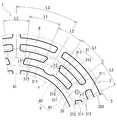
- FIG. 1 is a plan view showing an outline of a heater according to the first embodiment.
- FIG. 2 is a plan view illustrating a blank area provided in the heater according to the first embodiment.
- FIG. 3 is a cross-sectional view showing a state where the heater of FIG. 1 is cut along the (III)-(III) cutting line.
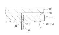
- FIG. 4 is a cross-sectional view showing the outline of the heater according to the second embodiment.
- FIG. 5 is a sectional view showing the outline of the heater according to the third embodiment.
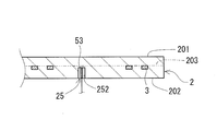
- FIG. 6 is a cross-sectional view showing the outline of the heater according to the fourth embodiment.
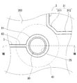
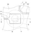
- FIG. 7 is a plan view showing an outline of a part of the heater according to the fifth embodiment.
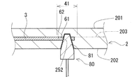
- FIG. 8 is a cross-sectional view showing a state in which the heater of FIG. 7 is cut along the (VIII)-(VIII) cutting line.
- FIG. 9 is a plan view schematically showing another example of a part of the heater according to the fifth embodiment.
- FIG. 10 is a sectional view showing a state in which the heater of FIG. 9 is cut along a line (X)-(X).
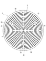
- FIG. 11 is a plan view showing the outline of the heater according to the sixth embodiment. 12 shows the sample No. It is a top view which shows the outline of the heater of 101.
- a heater having a configuration including a base material having a surface on which a heating target is placed and a heating element that heats the heating target via the base material it is required to uniformly heat the heating target. For that purpose, it is required to heat the entire surface of the base material so that the temperature difference becomes small. For this purpose, it has been studied to make the temperature distribution of the entire substrate uniform by devising the wiring pattern of the heating element. Here, it is required to reduce not only the temperature difference in the radial direction of the substrate but also the temperature difference in the circumferential direction of the substrate.
- One factor that causes the temperature difference is a portion such as the through hole of the lift pin, which is locally provided on the base material and in which the heating element cannot be arranged.
- the object to be heated is a semiconductor wafer, that is, in a heater for heating a semiconductor wafer in a semiconductor manufacturing apparatus, a more uniform temperature is required.
- an object of the present disclosure is to provide a heater that easily equalizes the temperature of the base material in the circumferential direction.
- the heater according to the present disclosure easily equalizes the temperature of the base material in the circumferential direction.
- a heater is A first surface on which a heating target is placed, and a base material having a second surface opposite to the first surface, A heater comprising a heating element arranged on a third surface parallel to the first surface of the base material, The base material has a hole opening at least in the second surface, The third surface does not have the heating element, and includes a plurality of blank areas defined as circular areas, The blank area is A first blank area including a region where the holes overlap in a direction perpendicular to the third surface, Including a second blank area other than the first blank area, The radius of the first blank area is the shortest distance between the center of gravity of the region where the holes overlap and the center of gravity and the edge of the heating element, The radius of the second blank area is the same as the radius of the first blank area, The respective centers of the first blank area and the second blank area are arranged at equal intervals on a circumference centered on the center of the envelope circle of the heating element on the third surface, The length of the interval of each of the
- the above configuration makes it easy to make the temperature of the base material in the circumferential direction uniform. This is because a plurality of blank areas where no heating element exists are arranged at equal intervals on the same circumference.
- the heater is provided with a through hole or the like as necessary, and a first blank area where the heating element does not exist is provided so as to include the through hole.
- the base material having the above configuration has a second blank area having the same size as the first blank area in the circumferential direction of the heater. Therefore, the interval between the blank areas adjacent in the circumferential direction is small.
- the temperature difference between the adjacent blank areas and the vicinity of the area is unlikely to be large, and The temperature difference in the circumferential direction can be reduced. Further, in the above configuration, since the intermediate portion of the heating element is provided between the blank areas adjacent to each other in the circumferential direction, comparison is made when the heating element is not provided over the entire area between the adjacent blank areas. Then, it is easy to reduce the temperature difference in the radial direction.
- the number of the second blank areas is such that the distance along the circumference between the centers of the second blank areas adjacent to each other in the circumferential direction without the first blank area interposed therebetween is on the circumference.
- the number is equal to or more than twice the length of one of the second blank areas.
- the above configuration makes it easy to provide an intermediate portion of the heating element between adjacent blank areas. Therefore, it becomes easy to design the wiring pattern of the heating element so that the temperature of the base material in the radial direction becomes uniform.
- the intermediate portion has a first intermediate portion in contact with the edge of the blank area,
- the first intermediate portion may be provided in an arc shape along the outline of the blank area.
- the temperature in the vicinity of the blank area does not easily drop because the first intermediate portion that contacts the edge of the blank area is provided in an arc shape that follows the outline of the blank area.
- the intermediate portion may include an arc-shaped second intermediate portion that is concentric with the circumference.
- the second intermediate portion is in an arc shape concentric with the circumference, so that the second intermediate portion has a space between the blank areas and a blank area as compared with the case where the second intermediate portion is along the radial direction of the base material. It is difficult for the temperature difference from the vicinity to become large, and it is easy to reduce the temperature difference in the circumferential direction of the base material.
- the temperature near the blank area is hard to drop because there are three or more contact points.
- the radius of the first blank area may be a distance that secures electrical insulation between the hole and the heating element in the first blank area.
- the above configuration can ensure electrical insulation between the member provided in the hole and the heating element.
- the first surface has a plurality of zones divided in the circumferential direction,
- the heating element is arranged so that the temperature of each of the plurality of zones can be independently controlled,
- the number of the blank areas may be one or more times the least common multiple of the number of the zones and the number of the first blank areas.
- the temperature of the base material can be precisely controlled by adjusting the temperature for each zone.
- the number of blank areas is equal to or more than one times the least common multiple, so that the number of blank areas arranged in each zone can be the same. Therefore, with the above configuration, it is easy to control the temperatures of the plurality of zones.
- the heating element may be embedded in the base material.
- the above configuration can protect the heating element from the external environment compared to the case where the heating element is exposed from the base material.
- the above-described configuration can transfer substantially all the heat generated by the heating element to the base material.
- the heating element may be fixed to the second surface of the base material.
- the above configuration makes it easier to form the heating element than when the heating element is embedded in the base material. Moreover, in the above configuration, since the heating element is exposed, it is easy to provide a terminal for supplying electric power to the heating element.
- the base material is A first substrate having the first surface, And a second substrate arranged on the opposite side of the first surface of the first substrate, The heating element may be interposed between the first base material and the second base material.
- the above configuration has a higher degree of freedom in design compared to the case where the base material is composed of a single member.
- the reason is that the first base material and the second base material can be made of different materials.
- the hole may be a through hole into which a lifter pin that supports the heating target is inserted.
- lifter pins are often used to lift the wafer for placing or replacing the wafer.
- the lifter pin is used to lift the wafer to be heated from below through the through hole of the base material.
- three lifter pins are used, and three through holes are arranged in the circumferential direction of the heater.
- the heating target may be a semiconductor wafer.
- the above configuration is particularly suitable for heating semiconductor wafers that require high uniformity because it is easy to make the temperature of the base material in the circumferential direction uniform.
- FIG. 1 is a plan view showing an outline of the heater 1 according to the first embodiment.
- FIG. 1 is a view of the third surface 203 of the base material 2 on which the heating elements 3 are arranged, as viewed from the first surface 201 side in a direction perpendicular to the first surface 201 (FIG. 3 ). is there.
- the first surface 201 side of the base material 2 may be referred to as “upper” and the opposite second surface 202 side may be referred to as “lower”.
- FIG. 2 is an enlarged plan view showing a fan-shaped area A1 surrounded by a broken line in FIG. FIG.
- FIG. 3 is a cross-sectional view showing a state in which the heater 1 of FIG. 1 is cut along the (III)-(III) cutting line.
- FIG. 3 is a cross section of the heater 1 taken along the vertical direction.
- the thickness of the base material 2 and the thickness of the heating element 3 in FIG. 3 are schematically shown and do not necessarily correspond to the actual thickness. This thickness refers to the length along the vertical direction.
- the heater 1 of this embodiment includes a base material 2 and a heating element 3.
- the base material 2 has a first surface 201 and a second surface 202 (FIG. 3).
- the heating target 90 is placed on the first surface 201.
- the second surface 202 is provided on the opposite side of the first surface 201.
- the heating element 3 is arranged on the third surface 203 parallel to the first surface 201 of the base material 2.
- the third surface 203 here is located on the first surface 201 side of the heating element 3.
- the third surface 203 is located at a distance from the first surface 201.
- the second surface 202 and the third surface 203 may be different surfaces or the same surface. In the heater 1 of this embodiment, the second surface 202 and the third surface 203 are different.
- the second surface 202 and the third surface 203 are the same, that is, the second surface 202 is also the third surface 203.
- the third surface 203 may be a virtual surface or a physical surface.
- the third surface 203 is a virtual surface inside the base material 2.
- the third surface 203 is an actual surface.
- the base material 2 has a hole 25 opened at least in the second surface 202.
- the hole portion 25 shows the through hole 251 opened on both the first surface 201 and the second surface 202.
- the heating element 3 is arranged on the third surface 203 of the base material 2.
- the heating element 3 includes a plurality of arc-shaped heat generating portions that extend in the circumferential direction of a predetermined circle, and a plurality of heat generating portions that connect the arc-shaped heat generating portions to each other in the radial direction of the circle.
- a continuous heat generating circuit is configured by combining these arc-shaped heat generating portions and the heat generating portions that connect them.
- the predetermined circle is a circle centered on the center a of the envelope circle of the heating element 3 on the third surface 203.
- the center of the circumscribed circle b of the base material 2 is also the center a (FIG. 1).
- the center a is indicated by a black dot in FIG.
- the circumscribing circle b is shown by a large circle of two-dot chain line in FIG.
- the circumscribed circle b of the chain double-dashed line shown in FIG. 1 is drawn larger than the actual circumscribed circle of the base material 2 shown in FIG. 1 for convenience of explanation.
- the third surface 203 has a plurality of predetermined blank areas 4.
- the plurality of blank areas 4 are areas where the heating element 3 does not exist on the circumference centered on the center a and are defined as areas that satisfy the following conditions.
- the plurality of blank areas 4 are arranged at equal intervals on the circumference.
- the plurality of blank areas 4 include a first blank area 41 and a second blank area 42.
- the first blank area 41 surrounds a region where the holes 25 overlap in the direction perpendicular to the third surface 203.
- the second blank area 42 is other than the first blank area 41, and does not include a region where the hole portion 25 overlaps.
- a heating target 90 is placed on the base material 2.
- the heating target 90 may be, for example, a wafer such as a semiconductor.
- the base material 2 is composed of a single member in this embodiment.
- the base material 2 may be composed of a plurality of members, as described in Embodiment 3 with reference to FIG. 5.
- the base material 2 being composed of a plurality of members means, for example, that the base material 2 is composed of the first base material 21 and the second base material 22 (FIG. 5 ).
- the base material 2 has a disk shape in this embodiment. That is, the center a is also the center of the base material 2.
- the first surface 201 of the base material 2 is flat. When the heating target 90 is a wafer, the first surface 201 is a wafer mounting surface.
- the first surface 201 is composed of one zone 20a as shown by the dotted line in FIG.
- the zone 20a refers to a section on the first surface 201 that includes a unit of a heat generating circuit whose temperature can be controlled independently. That is, the number of zones 20a corresponds to the number of heat generating circuits whose temperatures can be controlled independently.
- the heating element 3 is composed of one heating circuit.
- the dotted zone 20a shown in FIG. 1 is drawn larger than the first surface 201 shown in FIG. 1 for convenience of explanation.
- the first surface 201 may be composed of a plurality of zones 20a as described in the sixth embodiment with reference to FIG.
- the material of the base material 2 includes known ceramics and metals. Examples of ceramics include aluminum nitride and silicon carbide. Examples of the metal include aluminum, aluminum alloys, copper, copper alloys and the like. In addition, the base material 2 may be made of a composite material of a metal such as aluminum and the above ceramics. The material of the base material 2 is ceramics in this embodiment.
- a plurality of holes 25 are formed in the base material 2.
- Each hole 25 forms a space in which a member is inserted, a gas is circulated, and a member is housed.
- Each hole 25 is a contour line of an interface formed in the base material 2 when the base material 2 is seen through from above.
- the interface includes the interface between the base material 2 and the space such as a hole, and the interface between the base material 2 and a member inserted into the hole.
- the contour line of this interface constitutes a closed figure.
- the heating element 3 does not exist in each hole 25, and each hole 25 is separated from the heating element 3.
- the places where the plurality of holes 25 are formed are positions corresponding to the circumference centered on the center a. That the hole 25 is located at a position corresponding to the circumference means that the region where the hole 25 overlaps in the direction perpendicular to the third surface 203 is located on the circumference.
- the region where the holes 25 overlap is, for example, a region where the holes 25 intersect the third surface 203 or a projection region of the holes 25 which projects onto the third surface 203.
- the intersection region is a region surrounded by the inner peripheral surface of the hole 25 or the opening edge on the third surface 203.
- the projection area is defined as follows.
- the area surrounded by the extended inner peripheral surface of the third surface 203 is the projection area. That is, the projection area is an inner circumference circle moved on the third surface 203 when the inner circumference circle of the portion closest to the third surface 203 of the hole 25 is moved in the direction perpendicular to the third surface 203. It corresponds to the area surrounded by.
- the position of the hole portion 25 in the vertical direction on the base material 2 does not matter. That the plurality of holes 25 are located at positions corresponding to the circumference centered on the center a means that the centers of gravity of all the holes 25 are located at positions substantially corresponding to the same circumference.
- the center of gravity of the hole 25 is the center of gravity when the region formed by the contour is considered to be homogeneous when the contour of the region in the plane where the hole 25 overlaps is determined. When the area is circular, it coincides with the center of the circle.
- the center of gravity of the hole 25 is the center of gravity of the area of the intersection region or the center of gravity of the area of the projection region on the third surface 203.
- the centers of all the holes 25 correspond to positions on substantially the same circumference. It is in.
- Each hole 25 is a through hole 251 that penetrates the base material 2 in the vertical direction in this embodiment. That is, the openings of the through holes 251 are formed on the first surface 201 and the second surface 202 of the base material 2. For example, as described in Embodiment 4 with reference to FIG. 6, the hole 25 is open only on the second surface 202 of the base material 2 and does not penetrate the base material 2 in the vertical direction.
- the hole 252 may be used.
- the through hole 251 has a portion that intersects with the third surface 203. That is, the through hole 251 has a portion located on the same plane as the third surface 203.
- the blind hole 252 may have a portion located on the same plane as the third surface 203, or may be provided vertically offset with respect to the third surface 203. In the latter case, the blind hole 252 does not have a portion that intersects the third surface 203. That is, the blind hole 252 does not have a portion located on the same plane as the third surface 203.
- the through hole 251 is used, for example, to insert the lifter pin 51 as in this embodiment.
- the lifter pin 51 supports the heating target 90.
- the lower end side of the lifter pin 51 is connected to a lifting mechanism (not shown). By this elevating mechanism, the lifter pin 51 can be vertically moved up and down so as to be projected and retracted from the first surface 201.
- the through hole 251 is also used as an intake passage and an exhaust passage.
- the intake passage is used to evacuate the space between the heating target 90 and the first surface 201. By this evacuation, for example, the heating target 90 is attracted to the first surface 201.
- the exhaust passage is used for the purpose of cooling the heating target 90, supplying a gas necessary for the heating atmosphere, and the like.
- the number of the holes 25 can be appropriately selected according to the application of the holes 25.
- the number of the through holes 251 is usually three.
- the three through holes 251 are provided at equal intervals in the circumferential direction of the base material 2. That is, the intervals between the through holes 251 that are adjacent to each other in the circumferential direction are uniform in this embodiment.
- the three through holes 251 may be provided at different intervals in the circumferential direction. That is, the intervals between the adjacent through holes 251 may be non-uniform.
- the shape of the hole 25 is not particularly limited and can be appropriately selected.
- the shape of the hole 25 refers to the shape of the heater 1 when viewed from the direction perpendicular to the first surface 201.
- the shape of the hole 25 of this embodiment is circular.
- Each hole 25 has at least one cylindrical inner peripheral surface that intersects with the third surface 203.
- the hole portion 25 having one cylindrical inner peripheral surface may be a hole having a uniform inner diameter along the vertical direction, or a hole having an inner diameter gradually increasing from the upper side to the lower side. That is, the inner peripheral surface of the former hole 25 is cylindrical.
- the inner peripheral surface of the latter hole 25 has a cylindrical shape of a truncated cone.
- Examples of the hole portion 25 having two or more cylindrical inner peripheral surfaces include stepped holes in which inner peripheral surfaces having different inner diameters are formed in parallel in the vertical direction.
- the hole portion 25 has a single cylindrical inner peripheral surface and is a hole having a uniform inner diameter along the vertical direction.
- the heating element 3 serves as a heat source for heating the heating target 90 via the base material 2. As shown in FIG. 3, the heating element 3 is embedded in the base material 2 in this embodiment. By embedding the heating element 3 in the base material 2, the heater 1 of the present embodiment can transfer substantially all the heat generated in the heating element 3 to the base material 2.
- the heating element 3 may be fixed to the second surface 202 of the base material 2 as described in Embodiment 2 with reference to FIG. 4. Further, the heating element 3 is, as described in Embodiment 3 with reference to FIG. 5, between the plurality of members forming the base material 2, that is, between the first base material 21 and the second base material 22. May be interposed.
- the material of the heating element 3 is not particularly limited as long as it can heat the heating target 90 to a desired temperature.
- the material of the heating element 3 include known metals suitable for resistance heating.
- the metal include one selected from the group consisting of stainless steel, nickel, nickel alloys, silver, silver alloys, tungsten, tungsten alloys, molybdenum, molybdenum alloys, chromium, and chromium alloys.
- the nickel alloy include nichrome.
- the heating element 3 may have a main body made of the above metal and a coating layer made of resin and covering a region of the outer periphery of the main body that comes into contact with the base material 2. Good. Illustration of the coating layer is omitted.
- the heating element 3 may have a foil shape or a linear shape.
- the shape of the heating element 3 refers to the shape of the main body when a coating layer is provided.
- the heating element 3 of this embodiment has a foil shape.
- the wiring pattern of the heating element 3 is not particularly limited and can be appropriately selected according to the heating temperature and the required temperature distribution.
- the wiring pattern of the heating element 3 is provided with a plurality of blank areas 4 described later.
- the blank area 4 is a non-heating part where the heating element 3 does not exist.
- the wiring pattern of the heating element 3 shown in FIG. 1 is an example for facilitating the description.
- the heating element 3 has an intermediate portion 31 (FIG. 2).
- the intermediate portion 31 is formed between each of the blank areas 4 that are adjacent to each other in the circumferential direction.
- the blank areas 4 adjacent in the circumferential direction may be simply referred to as the adjacent blank areas 4. Since the intermediate portion 31 of the heating element 3 is formed between the adjacent blank areas 4, as compared to the case where the heating element 3 is not provided over the entire area between the adjacent blank areas 4, It is easy to reduce the temperature difference in the radial direction of the material 2. Therefore, the temperature of the base material 2 in the radial direction tends to be uniform.
- the term “between the blank areas 4 adjacent to each other in the circumferential direction” means the term between the blank areas 4 adjacent to each other in the circumferential direction between the inscribed circle c and the circumscribed circle d of the plurality of blank areas 4.
- the inscribed circle c and the circumscribed circle d are circles that are in contact with the inner peripheral side of the plurality of blank areas 4 and circles that are in contact with the outer peripheral side of the plurality of blank areas 4, as shown by the two-dot chain line in FIG.
- the inscribed circle c and the circumscribed circle d are circles centered on the center a.
- the case where the heating element 3 is not provided over the entire area between the adjacent blank areas 4 refers to the case where the heating element 3 is not provided in the annular area including all the blank areas 4.
- the annular area means all areas surrounded by the inscribed circle c and the circumscribed circle d.
- the intermediate section 31 has a first intermediate section 311 and a second intermediate section 312.
- the first intermediate portion 311 and the second intermediate portion 312 are formed in series with each other.
- the first intermediate portion 311 contacts the edge of the blank area 4.
- the first intermediate portion 311 is formed in an arc shape along the contour of the blank area 4. Therefore, it is difficult for the temperature around the blank area 4 to drop.
- a plurality of first intermediate portions 311 are provided at the edges of each of the first blank area 41 and the second blank area 42.
- the second intermediate portion 312 is formed in an arc shape along the circumferential direction.
- the second intermediate portion 312 is formed in an arc shape along the circumferential direction, as compared with the case where the second intermediate portion 312 is along the radial direction of the base material 2, the blank areas 4 and the blank areas 4 are blanked. The temperature difference with the vicinity of the area 4 is unlikely to increase, and the temperature difference in the circumferential direction can be easily reduced.
- the second intermediate portion 312 does not contact the edge portion of the blank area 4.
- a plurality of second intermediate portions 312 are provided between each of the blank areas 4 adjacent to each other.
- the number of terminals 80 can be appropriately selected according to the number of zones 20a of the first surface 201, that is, the number of heat generating circuits of the heat generating element 3.
- the number of terminals 80 is usually an even number. In the present embodiment, since the number of heat generating circuits is one, the number of terminals 80 is two.
- the two terminals 80 are arranged so as to face each other with the center a interposed therebetween at the innermost side in the radial direction of the heat generating element 3.
- Each terminal 80 is drawn out from the second surface 202 of the base material 2 via a connecting member or the like not shown.
- the material of each terminal 80 may be the same as the material of the heating element 3.
- Each blank area 4 is a portion where the heating element 3 does not exist (FIGS. 1 and 2). 1 and 2, each blank area 4 is shown by a small circle with a chain double-dashed line for convenience of explanation. Each blank area 4 is formed by avoiding the wiring pattern of the heating element 3.
- the centers of the plurality of blank areas 4 are arranged on the third surface 203 at equal intervals on the circumference centered on the center a.
- the fact that the centers of the plurality of blank areas 4 are arranged on the circumference does not have a strict meaning, but it means that they may be arranged practically on the circumference.
- Arranging substantially on the circumference means that the centers of all the blank areas 4 are not arranged geometrically on the same circumference as long as the temperature difference in the circumferential direction of the base material 2 satisfies the design range.
- a reference circle centered on the center a is taken, and the center of each blank area 4 is arranged in a region of 90% or more and 110% or less of the diameter of the reference circle.
- the reference circle is a circle passing through the center of each blank area 4 with the center a as the center, and the average of the diameters of all the circles is the circle.
- it is preferable that the centers of all the blank areas 4 are arranged on the same circumference.
- “equal spacing” does not mean strictly, but means that it is sufficient if the spacing is substantially equal.
- Substantially equal intervals means that if the temperature difference in the circumferential direction of the base material 2 satisfies the design range, not all of the distances connecting the centers of the adjacent blank areas 4 with a straight line may be the same. ..
- each of the above-mentioned distances may be within ⁇ 10% of the average value of all the above-mentioned distances. Of course, it is preferable that all the distances are the same.
- Adjacent blank areas 4 do not overlap each other.
- the intermediate portion 31 of the heating element 3 is provided between the adjacent blank areas 4 as described above. That is, the plurality of blank areas 4 are scattered on the same circumference.
- the interval L1 between the blank areas 4 adjacent to each other on the circumference where the centers of the plurality of blank areas 4 are arranged is equal to or longer than the length L2 of one blank area 4 on the circumference (FIG. 2).
- the interval L1 and the length L2 are both arc lengths.
- the distance L1 is preferably more than the length L2, and particularly preferably 1.5 times or more the length L2.
- the interval L1 is preferably, for example, three times or less than the length L2.
- the distance L1 is three times or less than the length L2, the distance between the adjacent blank areas 4 is not too large. Therefore, the temperature difference between the blank areas 4 adjacent to each other and the vicinity of the blank area 4 is unlikely to be large. Therefore, the temperature difference in the circumferential direction of the base material 2 tends to be small. Further, the distance L1 is preferably equal to or less than twice the length L2.
- Each of the plurality of blank areas 4 constitutes one of the first blank area 41 and the second blank area 42.
- the first blank area 41 is an area provided because the hole 25 is formed in the base material 2 and therefore the hole 25 and the heating element 3 need to be kept at a predetermined distance from the viewpoint of electrical insulation and the like. is there. Therefore, electrical insulation between the member provided in the hole 25 and the base material 2 is ensured.
- the first blank area 41 is a circular area including an area where the holes 25 overlap in the direction perpendicular to the third surface 203. Examples of the region where the holes 25 overlap are the intersection region or the projection region described above.
- the center position of the first blank area 41 is at a position overlapping the center of gravity of the hole 25 (Fig. 2).
- the center position of the first blank area 41 is a position overlapping the center of the hole 25.
- the radius r1 of the first blank area 41 is the shortest distance between the center of gravity of the region where the hole 25 overlaps and the edge of the heating element 3. That is, in the present embodiment, the radius r1 of the first blank area 41 is the shortest distance between the axis of the hole 25 and the edge of the heating element 3.
- the number of first blank areas 41 is the same as the number of holes 25 (FIG. 1). That is, the number of the first blank areas 41 of this embodiment is three. In the present embodiment, the three first blank areas 41 are provided at equal intervals in the circumferential direction.
- the second blank area 42 is an area provided in a place where the heating element 3 is intentionally avoided in order to make the temperature of the base material 2 in the circumferential direction uniform even though the heating element 3 can be laid. is there.
- the second blank area 42 is a circular area that does not overlap the area where the hole 25 overlaps. That is, the second blank area 42 does not overlap the hole 25 of the base material 2.
- the position of the center of the second blank area 42 is located on the circumference connecting the centers of the first blank areas 41 in the circumferential direction.
- the radius r2 of the second blank area 42 is the same as the radius r1 of the first blank area 41.
- the same radius does not have a strict meaning, and it means that the radius is substantially the same.
- the substantially same radius means that not all of the radii r2 of the second blank areas 42 need to be the same as long as the temperature difference in the circumferential direction of the base material 2 satisfies the design range.
- the radius r2 of the second blank area 42 may be within ⁇ 10% of the radius r1 of the first blank area 41.
- the number of the second blank areas 42 is the number of the first blank areas 41, the distance from the center of the heating element 3 in the first blank area 41, and the circle in which the centers of the plurality of blank areas 4 are arranged.
- the distance L3 between the centers of the second blank areas 42 adjacent to each other on the circumference, the distance between the centers of the first blank areas 41 adjacent to each other, and the like can be appropriately selected.
- the distance L3 is an arc length.
- the center-to-center distance is a straight line distance.
- the larger the number of second blank areas 42 the easier the temperature difference in the circumferential direction of the base material 2 becomes. However, if the number of the second blank areas 42 is too large, a temperature difference in the radial direction of the base material 2 may occur.
- the number of the second blank areas 42 is such that the distance L3 between the centers of the second blank areas 42 adjacent to each other on the circumference where the centers of the plurality of blank areas 4 are arranged is one of the first blank areas 42 on the circumference.
- the number is preferably twice the length L2 of the second blank area 42 or more.
- the number of the second blank areas 42 is preferably set such that the center-to-center distance between the adjacent second blank areas 42 is four times or more the radius r2 of the second blank areas 42. The reason is that it is easy to provide the intermediate portion 31 of the heating element 3 between the blank areas 4 adjacent to each other, and it is easy to design the wiring pattern of the heating element 3 so that the temperature of the base material 2 in the radial direction becomes uniform. Is.
- the number of the second blank areas 42 is preferably a number such that the distance L3 is 2.5 times or more of the L2. Further, it is preferable that the number of the second blank areas 42 is such that the distance between the centers of the adjacent second blank areas 42 is 5 times or more the radius r2 of the second blank areas 42.
- the adjacent second blank areas 42 refer to the second blank areas 42 that do not have the first blank area 41 between the second blank areas 42.
- the number of the second blank areas 42 is such that the distance L3 is 4 times or less of the distance L2. Further, the number of the second blank areas 42 is preferably a number such that the center-to-center distance between the adjacent second blank areas 42 is 8 times or less the radius r2 of the second blank areas 42. The reason is that the wiring pattern of the heating element 3 can be more easily designed to reduce the temperature difference in the circumferential direction of the base material 2. It is preferable that the number of the second blank areas 42 is such that the distance L3 is three times or less than the distance L2. Further, it is preferable that the number of the second blank areas 42 is further set such that the center-to-center distance between the adjacent second blank areas 42 is 6 times or less the radius r2 of the second blank areas 42.
- the number of second blank areas 42 is preferably twice or more the number of first blank areas 41, and more preferably three times or more the number of first blank areas 41. The reason is that the wiring pattern of the heating element 3 can be more easily designed to reduce the temperature difference in the circumferential direction of the base material 2.
- the number of second blank areas 42 is preferably 6 times or less the number of first blank areas 41, and more preferably 4 times or less the number of first blank areas 41. This is because the number of the second blank areas 42 is not too large, and the wiring pattern of the heating element 3 can be more easily designed to reduce the temperature difference in the radial direction of the base material 2.
- the number of the first blank areas 41 of this embodiment is three.
- the three first blank areas 41 are provided at equal intervals in the circumferential direction.
- the shape formed by connecting the centers of the adjacent first blank areas 41 is an equilateral triangle.
- the number of the second blank areas 42 is preferably a multiple of 3. That is, the number of the second blank areas 42 may be, for example, 3, 6, 9 or the like.
- the shapes formed by connecting the centers of the adjacent blank areas 4 are a regular hexagon, a regular hexagon, and a regular dodecagon, respectively.
- the number of the second blank areas 42 in this embodiment is nine.
- the number of the first blank areas 41 is three, unlike the present embodiment, the three first blank areas 41 are not provided at equal intervals in the circumferential direction,
- the shape formed by connecting the centers of the adjacent first blank areas 41 may be an isosceles triangle.
- the number of the second blank areas 42 may be, for example, 2, 4, 5, 7, or the like.
- the shapes formed by connecting the centers of the adjacent blank areas 4 are a regular pentagon, a regular heptagon, a regular octagon, and a regular decagon, respectively.
- the number of contact points between the heating element 3 and at least one of the first blank area 41 and the second blank area 42 is preferably three or more, for example. Of course, it is preferable that there are three or more contact points between the first blank area 41 and the heating element 3 and contact points between the second blank area 42 and the heating element 3. If the number of contact points is three or more, it is difficult for the temperature in the vicinity of the blank area 4 to drop.
- the number of contact points is preferably four or more.
- the contact points are preferably, for example, 8 points or less. If the number of contact points is 8 or less, it is difficult for the temperature near the blank area 4 to rise excessively. Further, the number of contact points is preferably 7 or less and 6 or less. In this embodiment, there are four contact points with the heating element 3 in all the first blank areas 41. Further, regarding the second blank area 42, there are a second blank area 42 having three contact points with the heating element 3 and a second blank area 42 having four contact points.
- the heater 1 of the present embodiment can be manufactured, for example, by combining a screen printing method and a hot press bonding method. Two ceramic substrates and a screen mask to which the heating element 3 can be transferred are prepared. As this screen mask, one capable of producing a wiring pattern in which the plurality of blank areas 4 described above is formed is used. Place a screen mask on one of the ceramic substrates. The paste to be the heating element 3 is applied to the ceramic substrate on which the screen mask is placed. The heating element 3 is transferred to the ceramic substrate using a squeegee. After the transfer of the heating element 3, the screen mask is removed. The other ceramics substrate is attached to the surface on which the heating element 3 is transferred and bonded by hot pressing.
- the heating element 3 By joining, the heating element 3 can be embedded in the base material 2. Then, the hole portion 25 can be formed by performing a drilling process on a predetermined position of the base material 2. In the case of the through hole 251, this drilling process is performed over the entire length of the base material 2 in the thickness direction.
- the heater 1 of the present embodiment can be manufactured through a step of preparing the heating element 3, a step of manufacturing the base material 2 in which the heating element 3 is embedded, and a step of forming the hole 25.
- the heating element 3 can be prepared by bending a metal wire. The bending of the metal wire is performed so as to form a wiring pattern in which the plurality of blank areas 4 described above are formed.
- the base material 2 in which the heating element 3 is embedded can be manufactured by the following procedure. A raw material powder containing a powder of the constituent material of the base material 2 and the heating element 3 are filled in a mold.
- the raw material powder may contain a sintering aid, a binder, and the like, if necessary.
- the raw material powder in the mold is pressure-molded. By this pressure molding, a powder compact having the heating element 3 embedded therein is produced. This powder compact is sintered.
- the holes 25 can be formed by making a hole in a predetermined position of the powder compact or the base material 2.
- the heater 1 of the present embodiment can easily make the temperature of the base material 2 in the circumferential direction uniform. This is because the plurality of blank areas 4 where the heating elements 3 do not exist are arranged at substantially equal intervals on the same circumference.
- the heater 1 of the present embodiment usually has, in addition to the first blank area 41, a second blank area 42 having the same size as the first blank area 41 in the circumferential direction of the heater 1. Therefore, the interval between the adjacent blank areas 4 is small. Therefore, even if the heating element 3 is formed between the blank areas 4 adjacent to each other, the temperature difference between the blank areas 4 adjacent to each other and the vicinity of the blank area 4 is less likely to increase, and the temperature difference in the circumferential direction of the base material 2 is small. The temperature difference can be reduced.
- the heater 1 of the present embodiment which facilitates uniforming the temperature of the base material 2 in the circumferential direction, can be suitably used as a heater for a wafer that requires a very small temperature difference in the circumferential direction of the base material 2. ..
- the heater 1 of the present embodiment can easily make the temperature of the substrate 2 in the radial direction uniform. This is because the heating element 3 has the intermediate portion 31 formed between the blank areas 4 adjacent to each other. The intermediate portion 31 can easily reduce the temperature difference in the radial direction as compared with the case where the heating element 3 is not provided over the entire circumference on the same circumference where the plurality of blank areas 4 are formed.
- the heater of the second embodiment can fix the heating element 3 to the second surface 202 of the base material 2. That is, in this embodiment, the second surface 202 is also the third surface 203.
- FIG. 4 is a sectional view showing a state in which the heater is cut at the same position as the sectional view shown in FIG. This point is the same in FIGS. 5 and 6 referred to in Embodiments 3 and 4 described later.
- the heating element 3 can be made of metal foil.
- the heater according to the present embodiment is the same as the heater 1 according to the first embodiment, except that the heating element 3 is installed on the second surface 202 of the base material 2 and the heating element 3 has a foil shape. ..
- the description of the configuration similar to that of the first embodiment in this embodiment is omitted.
- the heater can be manufactured, for example, through a step of forming the base material 2, a step of forming the hole 25, and a step of forming the heating element 3.
- the base material 2 can be produced by press-molding the raw material powder of the base material 2 filled in the mold to produce a powder compact, and sintering the powder compact.
- the holes 25 can be formed by powder molding or by making a hole in the base material 2.
- the heating element 3 is formed by printing a conductive paste having a predetermined wiring pattern on the second surface 202 of the base material 2 so that the plurality of blank areas 4 described above are formed, and sintering the conductive paste. You can do it.
- the heating element 3 may be formed either before or after drilling.
- the heating element sheet may be an integrated heating element sheet by attaching the metal foil to a resin film or sandwiching it with a resin film. By using the heating element sheet, handling during manufacturing becomes easy.
- the heater of the present embodiment can easily make the temperature of the base material 2 uniform in the circumferential direction and the radial direction. Moreover, in the heater of the present embodiment, since the heating element 3 is fixed to the second surface 202 of the base material 2, the heating element 3 is fixed as compared with the case where the heating element 3 is embedded in the base material 2. Easy to form. In the heater of this embodiment, the heating element 3 is not embedded in the base material 2 and is exposed from the base material 2, so that the terminal 80 (FIG. 1) can be easily provided at the end of the heating element 3.
- the base material 2 has a plurality of members, the hole 25 is formed by the through hole 251 and the blind hole 252, and the member provided in the hole 25 is the lifter pin 51.
- the heater 1 is different from the heater 1 of the first embodiment in that the fastening member 52 is not provided and the heating element 3 has a main body and a coating layer.
- the following description focuses on the differences from the first embodiment. The description of the same configuration as that of the first embodiment is omitted. These points are the same in the fourth and subsequent embodiments described later.
- the base material 2 is composed of two members, a first base material 21 and a second base material 22.
- the upper surface of the first base material 21 is the first surface 201.
- the second base material 22 is arranged to face the lower surface of the first base material 21.
- the lower surface of the second base material 22 is the second surface 202.
- the heating element 3 is interposed between the first base material 21 and the second base material 22.
- the surface of the first base material 21 that faces the second base material 22 and the surface of the second base material 22 that faces the first base material 21 form a third surface 203, respectively.
- the shapes of the first base material 21 and the second base material 22 include a disk shape.
- the materials of the first base material 21 and the second base material 22 may be the same or different.
- one material of the first base material 21 and the second base material 22 is metal, and the other material is ceramics.
- the material of the first base material 21 having the first surface 201 is metal
- the material of the second base material 22 having the second surface 202 is ceramics.
- the first base material 21 and the second base material 22 are fixed by a fastening member 52.
- Examples of the tightening member 52 include bolts.
- the hole portion 25 of this embodiment has a blind hole 252 formed in the first base material 21 and a through hole 251 formed in the second base material 22.
- the blind hole 252 is opened in the surface of the first base material 21 facing the second base material 22.
- the inner peripheral surface of the blind hole 252 is formed with a screw groove into which a bolt is tightened. Illustration of the thread groove is omitted.
- the through hole 251 is formed at a position facing the blind hole 252. That is, the blind hole 252 and the through hole 251 communicate with each other.
- the diameter of the through hole 251 is uniform in the axial direction.
- a counterbore may be formed in the through hole 251 on the second surface 202 side of the second base material 22. It is preferable that the shape and size of the spot facing correspond to the shape and size of the head of the bolt.
- the size of the spot facing is the diameter and depth of the spot facing.
- the size of the head is the diameter and thickness of the head.
- the heating element 3 can be composed of a main body made of metal and a coating layer made of resin and covering a region of the outer periphery of the main body that comes into contact with the base material 2. Illustration of the coating layer is omitted.
- the metal include the same metals as those of the heating element 3 of the first embodiment.
- the shape of the main body include a foil-shaped metal cut out in a desired pattern, and a foil-shaped one in which a desired pattern is drawn with a metal paste and dried.
- the resin include polyimide, silicon, epoxy, phenol and the like.
- the shape of the coating layer is preferably a film that does not hinder heat transfer and is easy to handle.
- the heating element 3 is interposed between the first base material 21 and the second base material 22, and the first base material 21 and the second base material 22 are fixed by the fastening member 52. Can be manufactured in.
- the heating element 3 including the main body and the coating layer can be manufactured by the following procedure, for example.
- the laminated film in which the metal foil and the first resin film are integrated is produced by stacking and hot pressing the metal foil and the first resin film.
- the sizes of the metal foil and the first resin film may be the same.
- a mask having a predetermined pattern is formed on the surface of the metal foil by the photoresist method. The etching removes the metal foil exposed from the mask. Therefore, the mask is formed such that the metal foil having a predetermined pattern is left on the resin film and the portions where the metal foil is removed form the plurality of blank areas 4 described above. By removing the mask, a laminated film in which a metal foil having a predetermined pattern is formed on the first resin film is produced.
- a second resin film having the same size as the first resin film is overlaid on the metal foil side of the laminated film and hot pressed. Through this procedure, the heating element 3 in which the metal foil having the predetermined wiring pattern is sandwiched between the first resin film and the second resin film is manufactured.
- the holes 25 of the first base material 21 and the second base material 22 may be formed by individually drilling the first base material 21 and the second base material 22, or may be formed by the first base. Alternatively, the first base material 21 and the second base material 22 may be combined with each other in a state where the material 21 and the second base material 22 are stacked to form a hole. When the hole portion 25 is formed in a state where the first base material 21 and the second base material 22 are overlapped with each other, the heating process is performed by sandwiching the heating element 3 between the first base material 21 and the second base material 22. You may go in the state.
- Drilling is performed on the first base material 21 and the second base material 22 in a state in which the heating element 3 including the main body portion and the coating layer is interposed between the first base material 21 and the second base material 22. In this case, holes are formed in the resin film of the heating element 3.
- the heater of the present embodiment can easily make the temperature of the base material 2 uniform in the circumferential direction and the radial direction. Moreover, the heater of this embodiment has a high degree of freedom in design as compared with the case where the base material 2 is composed of a single member. The reason is that the first base material 21 and the second base material 22 can be made of different materials.
- the heater 1 according to the fourth embodiment will be described with reference to FIG.
- the hole 25 is not the through hole 251 but the blind hole 252, and the member provided in the hole 25 is the temperature sensor 53 instead of the lifter pin 51. Different from the heater 1.
- the opening of the blind hole 252 is formed on the second surface 202 of the base material 2.
- the temperature sensor 53 is arranged inside the blind hole 252, for example.
- the type of the temperature sensor 53 include a thermocouple and a temperature measuring resistance element.
- the inside of the blind hole 252 is filled with a sealing material that fixes the temperature sensor 53 inside the blind hole 252. Illustration of the sealing material is omitted.
- the sealing material is not particularly limited as long as it is a material that can withstand the temperature at which the heating target 90 is heated, and can be appropriately selected.
- An example of the sealing material is silver solder.
- the heater 1 of this embodiment can be manufactured through the same steps as the steps of manufacturing the heater 1 of the first embodiment. The drilling process is performed halfway in the thickness direction of the base material 2.
- the heater of the present embodiment can easily make the temperature of the base material 2 uniform in the circumferential direction and the radial direction.
- the heater of the present embodiment can measure the temperature of the base material 2 by including the temperature sensor 53, so that the temperature of the base material 2 can be easily managed.
- the heater 1 according to the fifth embodiment will be described with reference to FIGS. 7 to 10.
- the hole 25 is not the through hole 251 but the blind hole 252 (FIGS. 8 and 10), and the member provided in the hole 25 is the terminal 80. It is different from the heater 1 of the first embodiment.
- the first surface 61 and the second surface 62 are provided on the third surface 203 on which the heating element 3 is arranged (FIGS. 7 and 9).
- the terminal 80 is connected to the first connecting portion 61.
- the second connecting portion 62 connects the first connecting portion 61 and the heating element 3. That is, the second connecting portion 62 is a portion from the first connecting portion 61 to the peripheral edge of the first blank area 41.
- the terminal 80, the first connecting portion 61, and the second connecting portion 62 are not included in the heating element 3. This is because the terminal 80, the first connecting portion 61, and the second connecting portion 62 are smaller than the heating element 3 and do not substantially achieve the function required of the heating element 3.
- the heat generation density of the terminal 80, the first connection portion 61, and the second connection portion 62 is lower than the heat generation density of the heating element 3.
- the heat generation density of the terminal 80, the first connection portion 61, and the second connection portion 62 is, for example, 1/3 times or less, further 1/6 times or less of the heat generation density of the heating element 3.
- the first connecting portion 61 may be provided with a desired through hole in the hole 25 as shown in FIGS. 7 and 8, or may not be provided with the above through hole as shown in FIGS. 9 and 10. Good.
- the shape of the first connecting portion 61 may be annular as shown in FIGS. 7 and 8, or may be rectangular as shown in FIGS. 9 and 10.
- the opening of the blind hole 252 is formed on the second surface 202 of the base material 2 (FIGS. 8 and 10).
- the terminal 80 is disposed inside the blind hole 252.
- the shape of the inner peripheral surface of the blind hole 252 can be appropriately selected according to the shape of the terminal 80.
- the shape of the inner peripheral surface of the blind hole 252 may be, for example, a circular truncated cone shape as shown in FIG.
- the inner diameter of the cylindrical inner peripheral surface of the truncated cone gradually increases from the upper side toward the lower side.
- the shape of the inner peripheral surface of the blind hole 252 may be, for example, a cylindrical shape as shown in FIG.
- the inner diameter of the cylindrical inner peripheral surface is uniform along the vertical direction.
- a metallized layer may be provided on the cylindrical inner peripheral surface of the truncated cone. Illustration of the metallized layer is omitted.
- the metallized layer has a portion directly connected to the first connection portion 61. Therefore, the metallized layer can favorably establish the electrical connection between the first connection portion 61 and the terminal 80. Examples of the material of the metallized layer include the same materials as those of the heating element 3.
- the shape of the terminal 80 may be columnar as shown in FIG. 8, or may be block-shaped as shown in FIG.
- the columnar terminal 80 has a tip portion 81 that is inserted into the hole portion 25.
- the shape of the tip 81 may be a shape corresponding to the shape of the inner peripheral surface of the hole 25. That is, the shape of the tip portion 81 of the present embodiment is a truncated cone shape with the tip side tapered.
- the tip 81 is inserted through the hole 25 so that the outer peripheral surface of the tip 81 contacts the inner peripheral surface of the through hole of the first connecting portion 61.
- the shape of the block-shaped terminal 80 may be circular although it is rectangular in FIG. 9 when the first surface 201 is viewed in plan from the first surface 201 side.
- the block-shaped terminal 80 is connected to the lower surface of the first connection portion 61.
- the material of the terminal 80 may be the same as the material of the heating element 3.
- the method of connecting the terminal 80 to the first connecting portion 61 is not particularly limited and can be appropriately selected, and a known method can be adopted.
- the heater of the present embodiment can easily make the temperature of the base material 2 uniform in the circumferential direction and the radial direction.
- the heater 1 according to the sixth embodiment will be described with reference to FIG.
- the heater 1 of the present embodiment differs from the heater 1 of the first embodiment mainly in that the first surface 201 has a plurality of zones 20a divided in the circumferential direction.
- the zone 20a refers to a section on the first surface 201 that includes a unit of a heating circuit whose temperature can be controlled independently, as described above.
- the number of zones 20a can be appropriately selected, and examples thereof include two, three, and four.
- the number of zones 20a in this embodiment is four.
- the size and shape of each zone 20a can be appropriately selected.
- the size of each zone 20a refers to the size of the area when the first surface 201 is viewed in plan from the first surface 201 side.
- the shape of each zone 20a refers to the shape of the first surface 201 when viewed in plan from the first surface 201 side.
- the size of each zone 20a may be the same or different.
- the size of each zone 20a of this embodiment is the same.
- the shape of each zone 20a in the present embodiment is a quadrant shape.
- the four zones 20a equally divide the first surface 201 in the circumferential direction.
- the heating element 3 has a plurality of heating circuits. Having a plurality of heat generating circuits means that there are a plurality of heat generating circuits whose temperatures can be independently controlled.
- the number of heat generating circuits corresponds to the number of zones 20a. That is, the number of heat generating circuits in this embodiment is four.
- the number of terminals 80 is 6 in this embodiment. Specifically, among the six terminals 80, each of the four terminals 80 is electrically connected to one end of each heating circuit. The four terminals 80 are arranged near the center a in this embodiment. Of the remaining two terminals 80, one terminal 80 is electrically connected to the other ends of the two adjacent heating circuits, and the other terminal 80 is the other of the remaining two adjacent heating circuits. Electrically connected to the end. The one terminal 80 and the other terminal 80 are arranged near the outer peripheral edge of the third surface 203 at positions facing each other with the center a therebetween. In the present embodiment, the one terminal 80 and the other terminal 80 are separately arranged on the left and right sides of the paper surface in FIG. 11.
- the number of blank areas 4 is at least one times the least common multiple of the number of zones 20a and the number of first blank areas 41.
- the number of zones 20a in this embodiment is four as described above.
- the number of the first blank areas 41 of this embodiment is three, as in the first embodiment. That is, the number of blank areas 4 is a multiple of 12.
- the number of blank areas 4 in this embodiment is 12.
- the heater of the present embodiment can easily make the temperature of the base material 2 uniform in the circumferential direction and the radial direction.
- the heater of the present embodiment can control the temperature of the first surface 201 precisely by having the plurality of zones 20a.
- the heater of the seventh embodiment is the same as the heater of the first embodiment except that a hole different from the hole through which the lifter pin is inserted is on the same circumference as the hole through which the lifter pin is inserted. Can be provided.
- a hole provided with the tightening member described in the third embodiment a hole provided with the temperature sensor described in the fourth embodiment, and a hole provided with the terminal described in the fifth embodiment. At least one kind of hole is mentioned.
- the base material of the heater of the first embodiment is composed of the first base material and the second base material as in the third embodiment, in addition to the hole through which the lifter pin is inserted, the description has been given in the third embodiment. Providing a hole in which the tightening member is provided may be mentioned.
- Test Example 1 In Test Example 1, the temperature uniformity of the base material provided in the heater was examined.
- Sample No. 1 Sample No. The heater 1 is the same as the heater 1 of the first embodiment described with reference to FIGS. 1 to 3. That is, the sample No.
- the first heater includes a base material 2, a heating element 3, and a plurality of blank areas 4.
- the base material 2 has a disk shape made of ceramics.
- the diameter of the base material 2 is 340 mm, and the thickness of the base material 2 is 15 mm.
- the heating element 3 was formed by bending a metal wire so as to form a wiring pattern in which a plurality of blank areas 4 described later are formed.
- the wiring pattern of the heating element 3 is also provided between the blank areas 4 adjacent to each other in the circumferential direction.
- the plurality of blank areas 4 are provided at equal intervals on the circumference centered on the center of the heating element 3.
- the plurality of blank areas 4 are composed of three first blank areas 41 including the hole portion 25 and nine second blank areas 42 that do not overlap the hole portion 25.
- the centers of the first blank area 41 and the second blank area 42 were provided 120 mm from the center of the heating element 3.
- the radius of the first blank area 41 and the second blank area 42 was 10 mm.
- Sample No. 101 Sample No. The heater of No. 101, as shown in FIG. It is different from the 1st heater. (1) Sample No. The second blank area 42 in the heater No. 1 is not provided. (2) Sample No. In the heater of No. 1, the wiring pattern of the heating element 3 is provided in the area where the second blank area 42 was provided. Except for the above points, Sample No. The heater of Sample No. 101 was Sample No. It was the same as the heater of No. 1. That is, the sample No. The heater 101 includes only three first blank areas 41 each having a plurality of areas including the holes 25. The three first blank areas 41 are provided at equal intervals on the circumference centered on the center of the heating element 3.
- the evaluation of the uniformity of the temperature of the base material 2 was performed by evaluating the uniformity of the temperature of the first surface 201 in the circumferential direction and the uniformity of the temperature of the first surface 201 in the radial direction.
- the evaluation of the temperature uniformity in the circumferential direction was performed by obtaining the difference between the highest temperature and the lowest temperature on the circumference passing through the centers of the first blank area 41 and the second blank area 42.
- the evaluation of the temperature uniformity in the radial direction was performed by obtaining the maximum difference between the maximum temperature and the minimum temperature on a straight line in the radial direction passing through the center of the heating element 3 and the center of each blank area 4.
- the temperature of the first surface 201 was determined by supplying power to the heating element 3 and setting the temperature of the first surface 201 to 400°C.
- the temperature of the first surface 201 was obtained by photographing with an infrared thermography camera capable of measuring the temperature distribution state.
- an infrared thermography camera As the infrared thermography camera, InfReC R550 manufactured by Nippon Avionics Co., Ltd. was used.
- Sample No. The heater No. 1 is the sample No. 1. It was found that the temperature in the circumferential direction of the base material 2 can be made uniform as compared with 101. In addition, the sample No. The heater No. 1 is the sample No. 1. It was found that the temperature of the base material 2 in the radial direction can be made uniform to the same extent as 101.
- the heater of appendix 1 since the above-mentioned separation distances are substantially the same, a plurality of areas where there are no heating elements are arranged at substantially equal intervals on the same circumference, and thus the above-mentioned (1) is achieved. Similar to the described heater according to one aspect of the present disclosure, it is easy to make the temperature in the circumferential direction of the substrate uniform.
- the heater is the same as the heater according to the aspect of the present disclosure described in (1) above. It is easy to make the temperature in the circumferential direction of the material uniform.
- the heater of Appendix 3 facilitates uniformizing the temperature of the base material in the circumferential direction. Further, in the heater of Appendix 3, since a part of the heating element is provided between the areas adjacent to each other in the circumferential direction, the heaters are adjacent to each other similarly to the heater according to the aspect of the present disclosure described in (1) above. The temperature difference in the radial direction can be easily reduced as compared with the case where the heating element is not provided over the entire area between the areas.
- the heater for heating a semiconductor wafer described in appendix 4 like the heater according to the aspect of the present disclosure described in (1) above, easily makes the temperature of the base material in the circumferential direction uniform. Further, in the heater for heating the semiconductor wafer of Supplementary Note 4, since a part of the heating element is provided between the areas adjacent to each other in the circumferential direction, the heater according to the aspect of the present disclosure described in (1) above. Similarly to the case, it is easier to reduce the temperature difference in the radial direction as compared with the case where the heating element is not provided over the entire area between the adjacent areas.
- the heater for heating the semiconductor wafer of Supplementary Note 4 since the hole portion is the through hole into which the lifter pin is inserted, the wafer can be lifted by the lifter pin for mounting or replacement of the wafer. Therefore, the heater for heating the semiconductor wafer described in Appendix 4 is suitable as a wafer heater.
Landscapes
- Chemical & Material Sciences (AREA)
- Engineering & Computer Science (AREA)
- Ceramic Engineering (AREA)
- Inorganic Chemistry (AREA)
- Resistance Heating (AREA)
- Surface Heating Bodies (AREA)
Abstract
Description
本出願は、2019年2月22日付の国際出願のPCT/JP2019/006873に基づく優先権を主張し、前記国際出願に記載された全ての記載内容を援用するものである。
加熱対象が載置される第一の面と、前記第一の面とは反対側の第二の面とを有する基材と、
前記基材の前記第一の面と平行な第三の面に配置された発熱体とを備えるヒータであって、
前記基材は、少なくとも前記第二の面に開口した穴部を有し、
前記第三の面は、前記発熱体が存在せず、円形状の領域として規定される複数のブランクエリアを含み、
前記ブランクエリアは、
前記第三の面に対して垂直な方向に前記穴部が重なる領域を含む第一のブランクエリアと、
前記第一のブランクエリア以外の第二のブランクエリアとを含み、
前記第一のブランクエリアの半径は、前記穴部が重なる領域の重心を中心として前記重心と前記発熱体の縁との間の最短距離であり、
前記第二のブランクエリアの半径は、前記第一のブランクエリアの前記半径と同一であり、
前記第一のブランクエリアと前記第二のブランクエリアの各中心は、前記第三の面における前記発熱体の包絡円の中心を中心とする円周上に等間隔に配置されており、
前記円周上での各前記ブランクエリアの間隔の長さは、前記円周上における一つの前記ブランクエリアの長さ以上であり、
前記発熱体は、周方向に隣り合う前記ブランクエリアの各々の間に設けられる中間部を有する。
加熱対象が載置される面を有する基材と、基材を介して加熱対象を加熱する発熱体とを備える形態のヒータにおいては、加熱対象を均一に加熱することが求められている。そのためには、基材の全面にわたって温度差が小さくなるように加熱することが求められる。この目的で、発熱体の配線パターンを工夫することで基材全体の温度分布を均一にすることが検討されている。ここでは、基材の径方向の温度差だけでなく、基材の周方向の温度差を小さくすることが求められている。温度差を生じさせる一つの要因は、リフトピンの貫通孔のように基材に局所的に設けられて発熱体を配置することができない部分である。特に加熱対象が半導体ウエハである場合、即ち半導体製造装置における半導体ウエハ加熱用のヒータにおいては、一層均一な温度が求められる。
本開示に係るヒータは、基材の周方向の温度を均一にし易い。
最初に本開示の実施態様を列記して説明する。
加熱対象が載置される第一の面と、前記第一の面とは反対側の第二の面とを有する基材と、
前記基材の前記第一の面と平行な第三の面に配置された発熱体とを備えるヒータであって、
前記基材は、少なくとも前記第二の面に開口した穴部を有し、
前記第三の面は、前記発熱体が存在せず、円形状の領域として規定される複数のブランクエリアを含み、
前記ブランクエリアは、
前記第三の面に対して垂直な方向に前記穴部が重なる領域を含む第一のブランクエリアと、
前記第一のブランクエリア以外の第二のブランクエリアとを含み、
前記第一のブランクエリアの半径は、前記穴部が重なる領域の重心を中心として前記重心と前記発熱体の縁との間の最短距離であり、
前記第二のブランクエリアの半径は、前記第一のブランクエリアの前記半径と同一であり、
前記第一のブランクエリアと前記第二のブランクエリアの各中心は、前記第三の面における前記発熱体の包絡円の中心を中心とする円周上に等間隔に配置されており、
前記円周上での各前記ブランクエリアの間隔の長さは、前記円周上における一つの前記ブランクエリアの長さ以上であり、
前記発熱体は、周方向に隣り合う前記ブランクエリアの各々の間に設けられる中間部を有する。
前記第二のブランクエリアの数は、前記第一のブランクエリアを間に介さずに周方向に隣り合う前記第二のブランクエリアの中心同士の前記円周上に沿った距離が前記円周上における一つの前記第二のブランクエリアの長さの2倍以上となる数であることが挙げられる。
前記中間部は、前記ブランクエリアの縁部に接する第一中間部を有し、
前記第一中間部は、前記ブランクエリアの輪郭に沿う円弧状に設けられていることが挙げられる。
前記中間部は、前記円周と同心の円弧状の第二中間部を有することが挙げられる。
前記第一のブランクエリア及び前記第二のブランクエリアの少なくとも一方における前記発熱体との接触箇所が3箇所以上であることが挙げられる。
前記第一のブランクエリアの前記半径は、前記第一のブランクエリアにおける前記穴部と前記発熱体との間の電気絶縁を確保する距離であることが挙げられる。
前記第一の面は、周方向に区分けされた複数のゾーンを有し、
前記発熱体は、前記複数のゾーンの各々の温度を独立して制御可能なように配置されており、
前記ブランクエリアの数は、前記ゾーンの数と前記第一のブランクエリアの数との最小公倍数の1倍以上であることが挙げられる。
前記発熱体は、前記基材に埋設されていることが挙げられる。
前記発熱体は、前記基材の前記第二の面に固定されていることが挙げられる。
前記基材は、
前記第一の面を有する第一基材と、
前記第一基材の前記第一の面とは反対側に配置される第二基材とを有し、
前記発熱体は、前記第一基材と前記第二基材との間に介在されることが挙げられる。
前記穴部は、前記加熱対象を支持するリフターピンが挿通される貫通孔であることが挙げられる。
前記加熱対象が半導体ウエハであることが挙げられる。
本開示の実施形態の詳細を、以下に説明する。図中の同一符号は同一名称物を示す。
〔ヒータ〕
図1から図3を参照して、実施形態1のヒータ1を説明する。図1は、実施形態1に係るヒータ1の概略を示す平面図である。図1は、基材2の発熱体3が配置された第三の面203を、第一の面201(図3)に垂直な方向であって第一の面201の側から見た図である。以下の説明は、基材2の第一の面201側を「上」とし、その反対側の第二の面202側を「下」と表現することがある。図2は、図1において破線で囲んだ扇型のエリアA1を拡大して示す平面図である。図3は、図1のヒータ1を(III)-(III)切断線で切断した状態を示す断面図である。図3は、ヒータ1を上下方向に沿って切断した断面である。図3の基材2の厚みや発熱体3の厚みなどは、模式的に示されたものであり、必ずしも実際の厚みに対応しているわけではない。この厚みは、上下方向に沿った長さをいう。
基材2には、加熱対象90が載置される。加熱対象90としては、例えば、半導体などのウエハが挙げられる。基材2は、本形態では単一の部材で構成されている。基材2は、実施形態3で図5を参照して説明するように、複数の部材で構成されていてもよい。基材2が複数の部材で構成されるとは、例えば、基材2が第一基材21と第二基材22とで構成されることが挙げられる(図5)。基材2の形状は、本形態では円盤状である。即ち、中心aは、基材2の中心でもある。基材2の第一の面201は、平らである。加熱対象90がウエハの場合、第一の面201はウエハの載置面である。第一の面201は、本形態では図1の点線で示すように1個のゾーン20aで構成されている。ゾーン20aは、独立して温度を制御可能な発熱回路の単位を含む第一の面201上の区画をいう。即ち、ゾーン20aの数は、温度を独立して制御可能な発熱回路の数に対応している。本形態のようにゾーン20aの数が1個である場合、発熱体3は1個の発熱回路で構成されていることをいう。図1に示す点線のゾーン20aは、説明の便宜上、図1に示す第一の面201よりも大きく描いている。なお、第一の面201は、実施形態6で図11を参照して説明するように、複数のゾーン20aで構成されていてもよい。
発熱体3は、基材2を介して加熱対象90を加熱するための熱源となる。発熱体3は、図3に示すように、本形態では基材2に埋設されている。発熱体3が基材2に埋設されることで、本形態のヒータ1は、発熱体3で発生される実質的に全ての熱を基材2に伝達させられる。発熱体3は、実施形態2で図4を参照して説明するように、基材2の第二の面202に固定されていてもよい。また、発熱体3は、実施形態3で図5を参照して説明するように、基材2を構成する複数の部材同士の間、即ち第一基材21と第二基材22との間に介在されていてもよい。
発熱体3には、端子80を介して電力が供給される(図1)。端子80の数は、第一の面201のゾーン20aの数、即ち発熱体3の発熱回路の数に応じて適宜選択できる。端子80の数は、通常、偶数である。本形態では、発熱回路の数が1個であるため、端子80の数は2個である。2個の端子80は、発熱体3の径方向の最も内側において、中心aを挟んで互いに対向配置されている。各端子80は、図示しない接続部材などを介して基材2の第二の面202から引き出されている。各端子80の材質は、発熱体3の材質と同様の材質が挙げられる。
各ブランクエリア4は、発熱体3が存在しない部分である(図1,図2)。図1,図2は、説明の便宜上、各ブランクエリア4を二点鎖線の小さな円で示している。各ブランクエリア4は、発熱体3の配線パターンの敷設が回避されることで形成される。複数のブランクエリア4の各中心は、第三の面203において、中心aを中心とする円周上に等間隔に配置されている。
第一のブランクエリア41は、穴部25が基材2に形成されていることで、電気絶縁などの観点から穴部25と発熱体3とを所定の間隔に保つ必要上、設けられる領域である。そのため、穴部25に設けられる部材と基材2との電気絶縁が確保される。第一のブランクエリア41は、第三の面203に対して垂直な方向に穴部25が重なる領域を含む円形状の領域である。上記穴部25が重なる領域としては、上述の交差領域又は投影領域が挙げられる。
第二のブランクエリア42は、基材2の周方向の温度を均一にするために、発熱体3を敷設できるにもかかわらず意図的に発熱体3の敷設を回避した箇所に設けた領域である。第二のブランクエリア42は、上記穴部25が重なる領域と重ならない円形状の領域である。即ち、第二のブランクエリア42は、基材2の穴部25と重ならない。第二のブランクエリア42の中心の位置は、第一のブランクエリア41の中心同士を周方向に結ぶ円周上に位置する。第二のブランクエリア42の半径r2は、第一のブランクエリア41の半径r1と同一である。ここで同一半径とは、厳密な意味では無く実質的に同一半径であればよいことをいう。実質的に同一半径とは、基材2の周方向の温度差が設計範囲を満たせば、第二のブランクエリア42の半径r2の全てが同一でなくてもよいことをいう。例えば、第二のブランクエリア42の半径r2が、第一のブランクエリア41の半径r1の±10%以内であることが挙げられる。勿論、第二のブランクエリア42の半径r2の全てが同一であることが好ましい。
本形態のヒータ1は、例えば、スクリーン印刷法とホットプレス接合法とを組み合わせて製造できる。2枚のセラミックス基板と、発熱体3を転写できるスクリーンマスクとを用意する。このスクリーンマスクは、上述の複数のブランクエリア4が形成される配線パターンを作製可能なものを用いる。一方のセラミックス基板にスクリーンマスクを置く。発熱体3となるペーストをスクリーンマスクの載せられたセラミックス基板に塗布する。スキージーを使用して発熱体3をセラミックス基板に転写する。発熱体3の転写後、スクリーンマスクを除去する。発熱体3が転写された面に他方のセラミックス基板を張り合わせてホットプレスで接合する。接合することで、発熱体3を基材2内に埋設できる。その後、基材2の所定の位置に対して穴あけ加工を施すことで穴部25を形成できる。貫通孔251の場合、この穴あけ加工は、基材2の厚み方向の全長にわたって行う。
本形態のヒータ1は、基材2の周方向の温度を均一にし易い。発熱体3の存在しない複数のブランクエリア4が、同一円周上に実質的に等間隔に配置されているからである。本形態のヒータ1は、通常、第一のブランクエリア41に加えて、第一のブランクエリア41と同等の大きさの第二のブランクエリア42をヒータ1の周方向に有する。そのため、隣り合うブランクエリア4同士の間隔が小さい。よって、隣り合うブランクエリア4同士の間に発熱体3が形成されていても、隣り合うブランクエリア4同士の間とブランクエリア4付近との温度差が大きくなり難く、基材2の周方向の温度差を小さくできる。このように基材2の周方向の温度を均一にし易い本形態のヒータ1は、基材2の周方向の温度差を極めて小さくすることが求められるウエハ用のヒータに好適に用いることができる。その上、本形態のヒータ1は、基材2の径方向の温度を均一にし易い。発熱体3が隣り合うブランクエリア4同士の間に形成される中間部31を有するからである。この中間部31は、複数のブランクエリア4が形成される同一円周上の全周にわたって発熱体3が設けられていない場合に比較して、径方向の温度差を小さくし易い。
〔ヒータ〕
図4に示すように、実施形態2のヒータは、発熱体3を基材2の第二の面202に固定することができる。即ち、本形態では、第二の面202が第三の面203でもある。図4は、図3に示す断面図と同様の位置で、ヒータを切断した状態を示す断面図である。この点は、後述する実施形態3及び実施形態4で参照する図5及び図6でも同様である。この発熱体3は、金属箔で構成できる。本形態のヒータは、発熱体3の設置箇所が基材2の第二の面202である点と発熱体3の形状が箔状である点以外は、実施形態1のヒータ1と同様である。本形態における実施形態1と同様の構成の説明は省略する。
ヒータは、例えば、基材2を作製する工程と、穴部25を形成する工程と、発熱体3を形成する工程とを経て製造できる。基材2の作製は、金型に充填された基材2の原料粉末を加圧成形して粉末成形体を作製し、粉末成形体を焼結することで行える。穴部25の形成は、粉末成形又は基材2に穴あけ加工を施すことで行える。発熱体3の形成は、上述の複数のブランクエリア4が形成されるように基材2の第二の面202に所定の配線パターンの導電ペーストを印刷し、その導電ペーストを焼結することで行える。発熱体3の形成は、穴あけ加工の前と後のどちらに行ってもよい。なお、本形態では発熱体3は金属箔のみの場合を説明したが、金属箔を樹脂フィルムに貼り付けたり樹脂フィルムで挟んだりして一体化した発熱体シートとしてもよい。発熱体シートとすることで、製造時の取り扱いが容易となる。
本形態のヒータは、実施形態1と同様、基材2の周方向及び径方向の温度を均一にし易い。その上、本形態のヒータは、発熱体3が基材2の第二の面202に固定されていることで、発熱体3を基材2に埋設する場合に比較して、発熱体3を形成し易い。また、本形態のヒータは、発熱体3が基材2に埋設されておらず、基材2から露出していることで、発熱体3の端部に端子80(図1)を設け易い。
〔ヒータ〕
実施形態3のヒータを、図5を参照して説明する。本形態のヒータは、基材2が複数の部材を有する点と、穴部25が貫通孔251と止まり穴252とで形成されている点と、穴部25に設けられる部材がリフターピン51ではなく締付部材52である点と、発熱体3が本体部と被覆層とを有する点とが、実施形態1のヒータ1と相違する。以下の説明は、実施形態1との相違点を中心に行う。実施形態1と同様の構成の説明は省略する。これら点は、後述する実施形態4以降でも同様である。
基材2は、第一基材21と第二基材22の2個の部材で構成されている。第一基材21の上面が第一の面201である。第二基材22は、第一基材21の下面に対向配置される。第二基材22の下面が第二の面202である。この第一基材21と第二基材22との間に、発熱体3が介在される。第一基材21における第二基材22との対向面と、第二基材22における第一基材21との対向面とがそれぞれ第三の面203を構成する。第一基材21と第二基材22の形状は、円盤状が挙げられる。第一基材21と第二基材22の材質は、同一としてもよいし異ならせてもよい。材質を異ならせる場合、例えば、第一基材21と第二基材22の一方の材質が金属であり、他方の材質がセラミックスが挙げられる。本形態では、第一の面201を有する第一基材21の材質が金属、第二の面202を有する第二基材22の材質がセラミックスで構成されている。
発熱体3は、金属からなる本体部と、樹脂からなり、本体部の外周のうち基材2と接触する領域を覆う被覆層とで構成することができる。被覆層の図示は省略している。金属としては、実施形態1の発熱体3と同様の金属が挙げられる。本体部の形状は、箔状の金属を所望のパターンに切り抜いたものや、金属ペーストにより所望のパターンを描いて乾燥させた箔状のものなどが挙げられる。樹脂としては、例えば、ポリイミド、シリコン、エポキシ、フェノールなどが挙げられる。被覆層の形状は、熱伝達を妨げず、かつ取り扱いが容易なフィルムが好ましい。
本形態のヒータは、第一基材21と第二基材22との間に発熱体3を介在させて、第一基材21と第二基材22とを締付部材52で固定することで製造できる。
本形態のヒータは、実施形態1と同様、基材2の周方向及び径方向の温度を均一にし易い。その上、本形態のヒータは、基材2が単一の部材で構成されている場合に比較して、設計の自由度が高い。その理由は、第一基材21と第二基材22とを異なる材質で構成したりできるからである。
〔ヒータ〕
実施形態4のヒータ1を、図6を参照して説明する。本形態のヒータ1は、穴部25が貫通孔251ではなく止まり穴252である点と、穴部25に設けられる部材がリフターピン51ではなく温度センサ53である点とが、実施形態1のヒータ1と相違する。
本形態のヒータは、実施形態1と同様、基材2の周方向及び径方向の温度を均一にし易い。その上、本形態のヒータは、温度センサ53を有することで基材2の温度を測定できるので、基材2の温度を管理し易い。
〔ヒータ〕
実施形態5のヒータ1を図7から図10を参照して説明する。本形態のヒータ1は、主に、穴部25が貫通孔251ではなく止まり穴252(図8,図10)である点と、穴部25に設けられる部材が端子80である点とが、実施形態1のヒータ1と相違する。
本形態のヒータは、実施形態1と同様、基材2の周方向及び径方向の温度を均一にし易い。
〔ヒータ〕
実施形態6のヒータ1を図11を参照して説明する。本形態のヒータ1は、主に第一の面201が周方向に区分けされた複数のゾーン20aを有する点が、実施形態1のヒータ1と相違する。
本形態のヒータは、実施形態1と同様、基材2の周方向及び径方向の温度を均一にし易い。その上、本形態のヒータは、複数のゾーン20aを有することで第一の面201の温度を緻密に制御できる。
図示は省略しているものの、実施形態7のヒータは、実施形態1のヒータにおいて、リフターピンが挿通される穴部とは別の穴部をリフターピンが挿通される穴部と同一円周上に設けることができる。別の穴部としては、実施形態3で説明した締付部材が設けられる穴部、実施形態4で説明した温度センサが設けられる穴部、及び実施形態5で説明した端子が設けられる穴部の少なくとも一種の穴部が挙げられる。例えば、実施形態1のヒータの基材を実施形態3のような第一基材と第二基材とで構成する場合、リフターピンが挿通される穴部の他に、実施形態3で説明した締付部材が設けられる穴部を設けることが挙げられる。
試験例1は、ヒータに備わる基材の温度の均一性を調べた。
試料No.1のヒータは、図1から図3を参照して説明した実施形態1のヒータ1と同様である。即ち、試料No.1のヒータは、基材2と発熱体3と複数のブランクエリア4とを備える。基材2は、セラミックスからなる円盤状である。基材2の直径は340mmで、基材2の厚みは15mmである。発熱体3は、後述する複数のブランクエリア4が形成される配線パターンとなるように金属線を曲げて構成した。発熱体3の配線パターンは、周方向に隣り合うブランクエリア4同士の間にも設けられている。複数のブランクエリア4は、発熱体3の中心を中心とする円周上に等間隔に設けられている。複数のブランクエリア4は、穴部25を含む3個の第一のブランクエリア41と穴部25に重ならない9個の第二のブランクエリア42とで構成した。第一のブランクエリア41と第二のブランクエリア42の中心は、発熱体3の中心から120mmの地点に設けた。第一のブランクエリア41と第二のブランクエリア42の半径は、10mmとした。
試料No.101のヒータは、図12に示すように、次の点で試料No.1のヒータと異なる。
(1)試料No.1のヒータにおける第二のブランクエリア42を備えていない。
(2)試料No.1のヒータにおいて第二のブランクエリア42が設けられていた領域に発熱体3の配線パターンが設けられている。
以上の点を除き、試料No.101のヒータは、試料No.1のヒータと同様とした。即ち、試料No.101のヒータは、複数のエリアが穴部25を含む3個の第一のブランクエリア41のみで構成されている。3個の第一のブランクエリア41は、発熱体3の中心を中心とする円周上に等間隔に設けられている。
基材2における温度の均一性の評価は、第一の面201における周方向の温度の均一性と、第一の面201における径方向の温度の均一性と、を評価することで行った。周方向における温度の均一性の評価は、第一のブランクエリア41及び第二のブランクエリア42の中心を通る円周上の最高温度と最低温度との差を求めることで行った。径方向における温度の均一性の評価は、発熱体3の中心と各ブランクエリア4の中心とを通る半径方向の直線上での最高温度と最低温度との最大差を求めることで行った。各評価は、第一の面201の温度は、発熱体3に電力を供給して第一の面201の設定温度を400℃として行った。第一の面201の温度は、温度の分布状態を測定できる赤外線サーモグラフィカメラで撮影して求めた。赤外線サーモグラフィカメラは、日本アビオニクス社製InfReC R550を用いた。
本開示は、上述の説明とも重複する以下の態様を含む。
加熱対象が載置される第一の面と、前記第一の面とは反対側の第二の面とを有する基材と、
前記基材の前記第一の面と平行な第三の面に配置された発熱体とを備えるヒータであって、
前記基材は、少なくとも前記第二の面に開口した穴部を有し、
前記第三の面は、前記発熱体が存在せず、円形状の領域として規定される複数のブランクエリアを含み、
前記ブランクエリアは、
前記第三の面に対して垂直な方向に前記穴部が重なる領域を含む第一のブランクエリアと、
前記第一のブランクエリア以外の第二のブランクエリアとを含み、
前記第一のブランクエリアの半径は、前記穴部が重なる領域の重心を中心として前記重心と前記発熱体の縁との間の最短距離であり、
前記第二のブランクエリアの半径は、前記第一のブランクエリアの前記半径と同一であり、
前記第一のブランクエリアと前記第二のブランクエリアの各中心は、前記第三の面における前記発熱体の包絡円の中心を中心とする円周上に等間隔に配置されており、
前記円周上での各前記ブランクエリアの間隔の長さは、前記円周上における一つの前記ブランクエリアの長さ以上であり、
前記複数のブランクエリアの隣り合うブランクエリア間の離間距離が、全ての前記離間距離の平均値に対して±10%以内であり、
前記発熱体は、周方向に隣り合う前記ブランクエリアの各々の間に設けられる中間部を有する、
ヒータ。
加熱対象が載置される第一の面と、前記第一の面とは反対側の第二の面とを有する基材と、
前記基材の前記第一の面と平行な第三の面に配置された発熱体とを備えるヒータであって、
前記基材は、少なくとも前記第二の面に開口した穴部を有し、
前記第三の面は、前記発熱体が存在せず、円形状の領域として規定される複数のブランクエリアを含み、
前記ブランクエリアは、
前記第三の面に対して垂直な方向に前記穴部が重なる領域を含む第一のブランクエリアと、
前記第一のブランクエリア以外の第二のブランクエリアとを含み、
前記第一のブランクエリアの半径は、前記穴部が重なる領域の重心を中心として前記重心と前記発熱体の縁との間の最短距離であり、
前記第二のブランクエリアの半径は、前記第一のブランクエリアの半径の±10%以内であり、
前記第一のブランクエリアと前記第二のブランクエリアの各中心は、前記第三の面における前記発熱体の包絡円の中心を中心とする円周上に等間隔に配置されており、
前記円周上での各前記ブランクエリアの間隔の長さは、前記円周上における一つの前記ブランクエリアの長さ以上であり、
前記発熱体は、周方向に隣り合う前記ブランクエリアの各々の間に設けられる中間部を有する、
ヒータ。
加熱対象が載置される第一の面と、前記第一の面とは反対側の第二の面とを有する基材と、
前記基材の前記第一の面と平行な第三の面に配置された発熱体とを備えるヒータであって、
前記基材は、少なくとも前記第二の面に開口した穴部を有し、
前記第三の面は、前記発熱体が存在せず、円形状の領域として規定される複数のブランクエリアを含み、
前記ブランクエリアは、
前記第三の面に対して垂直な方向に前記穴部が重なる領域を含む第一のブランクエリアと、
前記第一のブランクエリア以外の第二のブランクエリアとを含み、
前記第一のブランクエリアの半径は、前記穴部が重なる領域の重心を中心として前記重心と前記発熱体の縁との間の最短距離であり、
前記第二のブランクエリアの半径は、前記第一のブランクエリアの前記半径と同一であり、
前記第一のブランクエリアと前記第二のブランクエリアの各中心は、前記第三の面における前記発熱体の包絡円の中心を中心とする円周上に等間隔に配置されており、
前記円周上での各前記ブランクエリアの間隔の長さは、前記円周上における一つの前記ブランクエリアの長さ以上であり、
前記円周上の隣り合う前記ブランクエリアの間には前記発熱体の一部が配置されている、
ヒータ。
加熱対象が載置される第一の面と、前記第一の面とは反対側の第二の面とを有する基材と、
前記基材の前記第一の面と平行な第三の面に配置された発熱体とを備える半導体ウエハ加熱用のヒータであって、
前記基材は、少なくとも前記第二の面に開口した穴部を有し、
前記第三の面は、前記発熱体が存在せず、円形状の領域として規定される複数のブランクエリアを含み、
前記ブランクエリアは、
前記第三の面に対して垂直な方向に前記穴部が重なる領域を含む第一のブランクエリアと、
前記第一のブランクエリア以外の第二のブランクエリアとを含み、
前記第一のブランクエリアの半径は、前記穴部が重なる領域の重心を中心として前記重心と前記発熱体の縁との間の最短距離であり、
前記第二のブランクエリアの半径は、前記第一のブランクエリアの前記半径と同一であり、
前記第一のブランクエリアと前記第二のブランクエリアの各中心は、前記第三の面における前記発熱体の包絡円の中心を中心とする円周上に等間隔に配置されており、
前記円周上での各前記ブランクエリアの間隔の長さは、前記円周上における一つの前記ブランクエリアの長さ以上であり、
前記円周上の隣り合う前記ブランクエリアの間には前記発熱体の一部が配置されており、
前記発熱体は、前記基材に埋設されており、
前記穴部は、リフターピンが挿通されるための貫通孔である、
半導体ウエハ加熱用のヒータ。
2 基材
201 第一の面
202 第二の面
203 第三の面
20a ゾーン
21 第一基材
22 第二基材
25 穴部
251 貫通孔
252 止まり穴
3 発熱体
31 中間部
311 第一中間部
312 第二中間部
4 ブランクエリア
41 第一のブランクエリア
42 第二のブランクエリア
51 リフターピン
52 締付部材
53 温度センサ
61 第一接続部
62 第二接続部
80 端子
81 先端部
90 加熱対象
A1 扇形のエリア
a 中心
b 外接円
c 内接円
d 外接円
L1、L3 距離
L2 長さ
Claims (12)
- 加熱対象が載置される第一の面と、前記第一の面とは反対側の第二の面とを有する基材と、
前記基材の前記第一の面と平行な第三の面に配置された発熱体とを備えるヒータであって、
前記基材は、少なくとも前記第二の面に開口した穴部を有し、
前記第三の面は、前記発熱体が存在せず、円形状の領域として規定される複数のブランクエリアを含み、
前記ブランクエリアは、
前記第三の面に対して垂直な方向に前記穴部が重なる領域を含む第一のブランクエリアと、
前記第一のブランクエリア以外の第二のブランクエリアとを含み、
前記第一のブランクエリアの半径は、前記穴部が重なる領域の重心を中心として前記重心と前記発熱体の縁との間の最短距離であり、
前記第二のブランクエリアの半径は、前記第一のブランクエリアの前記半径と同一であり、
前記第一のブランクエリアと前記第二のブランクエリアの各中心は、前記第三の面における前記発熱体の包絡円の中心を中心とする円周上に等間隔に配置されており、
前記円周上での各前記ブランクエリアの間隔の長さは、前記円周上における一つの前記ブランクエリアの長さ以上であり、
前記発熱体は、周方向に隣り合う前記ブランクエリアの各々の間に設けられる中間部を有する、
ヒータ。 - 前記第二のブランクエリアの数は、前記第一のブランクエリアを間に介さずに周方向に隣り合う前記第二のブランクエリアの中心同士の前記円周上に沿った距離が前記円周上における一つの前記第二のブランクエリアの長さの2倍以上となる数である請求項1に記載のヒータ。
- 前記中間部は、前記ブランクエリアの縁部に接する第一中間部を有し、
前記第一中間部は、前記ブランクエリアの輪郭に沿う円弧状に設けられている請求項1又は請求項2に記載のヒータ。 - 前記中間部は、前記円周と同心の円弧状の第二中間部を有する請求項1から請求項3のいずれか1項に記載のヒータ。
- 前記第一のブランクエリア及び前記第二のブランクエリアの少なくとも一方における前記発熱体との接触箇所が3箇所以上である請求項1から請求項4のいずれか1項に記載のヒータ。
- 前記第一のブランクエリアの前記半径は、前記第一のブランクエリアにおける前記穴部と前記発熱体との間の電気絶縁を確保する距離である請求項1から請求項5のいずれか1項に記載のヒータ。
- 前記第一の面は、周方向に区分けされた複数のゾーンを有し、
前記発熱体は、前記複数のゾーンの各々の温度を独立して制御可能なように配置されており、
前記ブランクエリアの数は、前記ゾーンの数と前記第一のブランクエリアの数との最小公倍数の1倍以上である請求項1から請求項6のいずれか1項に記載のヒータ。 - 前記発熱体は、前記基材に埋設されている請求項1から請求項7のいずれか1項に記載のヒータ。
- 前記発熱体は、前記基材の前記第二の面に固定されている請求項1から請求項7のいずれか1項に記載のヒータ。
- 前記基材は、
前記第一の面を有する第一基材と、
前記第一基材の前記第一の面とは反対側に配置される第二基材とを有し、
前記発熱体は、前記第一基材と前記第二基材との間に介在される請求項1から請求項7のいずれか1項に記載のヒータ。 - 前記穴部は、前記加熱対象を支持するリフターピンが挿通される貫通孔である請求項1から請求項10のいずれか1項に記載のヒータ。
- 前記加熱対象が半導体ウエハである請求項1から請求項11のいずれか1項に記載のヒータ。
Priority Applications (3)
| Application Number | Priority Date | Filing Date | Title |
|---|---|---|---|
| US17/429,351 US12063721B2 (en) | 2019-02-22 | 2020-01-20 | Heater |
| JP2020533176A JP6840349B2 (ja) | 2019-02-22 | 2020-01-20 | ヒータ |
| KR1020217025529A KR102592798B1 (ko) | 2019-02-22 | 2020-01-20 | 히터 |
Applications Claiming Priority (2)
| Application Number | Priority Date | Filing Date | Title |
|---|---|---|---|
| JP2019006873 | 2019-02-22 | ||
| JPPCT/JP2019/006873 | 2019-02-22 |
Publications (1)
| Publication Number | Publication Date |
|---|---|
| WO2020170682A1 true WO2020170682A1 (ja) | 2020-08-27 |
Family
ID=72143465
Family Applications (1)
| Application Number | Title | Priority Date | Filing Date |
|---|---|---|---|
| PCT/JP2020/001768 Ceased WO2020170682A1 (ja) | 2019-02-22 | 2020-01-20 | ヒータ |
Country Status (4)
| Country | Link |
|---|---|
| US (1) | US12063721B2 (ja) |
| JP (1) | JP6840349B2 (ja) |
| KR (1) | KR102592798B1 (ja) |
| WO (1) | WO2020170682A1 (ja) |
Cited By (2)
| Publication number | Priority date | Publication date | Assignee | Title |
|---|---|---|---|---|
| JP2023000165A (ja) * | 2021-06-17 | 2023-01-04 | 日本特殊陶業株式会社 | セラミックスヒータおよび保持部材 |
| JP2023141826A (ja) * | 2022-03-24 | 2023-10-05 | 日本特殊陶業株式会社 | 保持部材 |
Families Citing this family (1)
| Publication number | Priority date | Publication date | Assignee | Title |
|---|---|---|---|---|
| DE102020123389A1 (de) * | 2020-09-08 | 2022-03-10 | Ampack Gmbh | Verdampfervorrichtung, insbesondere Sterilisationsverdampfervorrichtung, zu einem Verdampfen einer Flüssigkeit und/oder eines Aerosols |
Citations (3)
| Publication number | Priority date | Publication date | Assignee | Title |
|---|---|---|---|---|
| JP2001135464A (ja) * | 1999-08-10 | 2001-05-18 | Ibiden Co Ltd | セラミックヒータ |
| JP2003524885A (ja) * | 1999-09-29 | 2003-08-19 | 東京エレクトロン株式会社 | 多重領域抵抗ヒータ |
| JP2004079392A (ja) * | 2002-08-20 | 2004-03-11 | Ibiden Co Ltd | 金属ヒータ |
Family Cites Families (4)
| Publication number | Priority date | Publication date | Assignee | Title |
|---|---|---|---|---|
| US6740853B1 (en) * | 1999-09-29 | 2004-05-25 | Tokyo Electron Limited | Multi-zone resistance heater |
| WO2004019658A1 (ja) * | 2002-08-20 | 2004-03-04 | Ibiden Co., Ltd. | 金属ヒータ |
| JP4119211B2 (ja) | 2002-09-13 | 2008-07-16 | 日本碍子株式会社 | 加熱装置 |
| CN115087371A (zh) * | 2021-01-14 | 2022-09-20 | 韩国烟草人参公社 | 气溶胶生成装置的加热器和包括加热器的气溶胶生成装置 |
-
2020
- 2020-01-20 WO PCT/JP2020/001768 patent/WO2020170682A1/ja not_active Ceased
- 2020-01-20 JP JP2020533176A patent/JP6840349B2/ja active Active
- 2020-01-20 US US17/429,351 patent/US12063721B2/en active Active
- 2020-01-20 KR KR1020217025529A patent/KR102592798B1/ko active Active
Patent Citations (3)
| Publication number | Priority date | Publication date | Assignee | Title |
|---|---|---|---|---|
| JP2001135464A (ja) * | 1999-08-10 | 2001-05-18 | Ibiden Co Ltd | セラミックヒータ |
| JP2003524885A (ja) * | 1999-09-29 | 2003-08-19 | 東京エレクトロン株式会社 | 多重領域抵抗ヒータ |
| JP2004079392A (ja) * | 2002-08-20 | 2004-03-11 | Ibiden Co Ltd | 金属ヒータ |
Cited By (2)
| Publication number | Priority date | Publication date | Assignee | Title |
|---|---|---|---|---|
| JP2023000165A (ja) * | 2021-06-17 | 2023-01-04 | 日本特殊陶業株式会社 | セラミックスヒータおよび保持部材 |
| JP2023141826A (ja) * | 2022-03-24 | 2023-10-05 | 日本特殊陶業株式会社 | 保持部材 |
Also Published As
| Publication number | Publication date |
|---|---|
| US12063721B2 (en) | 2024-08-13 |
| KR102592798B1 (ko) | 2023-10-20 |
| JP6840349B2 (ja) | 2021-03-10 |
| US20220151027A1 (en) | 2022-05-12 |
| KR20210114458A (ko) | 2021-09-23 |
| JPWO2020170682A1 (ja) | 2021-03-11 |
Similar Documents
| Publication | Publication Date | Title |
|---|---|---|
| CN107113921B (zh) | 静电卡盘加热器 | |
| KR100725123B1 (ko) | 히터, 웨이퍼 가열장치 및 이 히터의 제조방법 | |
| US8525418B2 (en) | Electrostatic chuck | |
| JP6840349B2 (ja) | ヒータ | |
| JP6461300B1 (ja) | セラミック装置 | |
| JP2013247342A (ja) | 静電チャック及び静電チャックの製造方法 | |
| KR102062751B1 (ko) | 정전 척 히터 | |
| WO2001039551A1 (en) | Ceramic heater | |
| JP2017157617A (ja) | 加熱部材及び静電チャック | |
| WO2020213368A1 (ja) | 保持装置の製造方法、保持装置用の構造体の製造方法および保持装置 | |
| CN107548231B (zh) | 柔性基板以及金属配线接合结构的制法 | |
| TWI839960B (zh) | 晶圓載置台 | |
| JP2018157186A (ja) | セラミックスヒータ及び静電チャック並びにセラミックスヒータの製造方法 | |
| JP4567249B2 (ja) | 静電チャック | |
| TWI724951B (zh) | 一體式加熱器及製造方法 | |
| JP2022078929A (ja) | 基板固定装置、静電チャック及び静電チャックの製造方法 | |
| US20210242046A1 (en) | Ceramic heater | |
| KR102894647B1 (ko) | 히터 | |
| JP2001230306A (ja) | セラミック基板 | |
| US20220256655A1 (en) | Ceramic heater | |
| JP2018006269A (ja) | セラミックスヒータ | |
| JP7636234B2 (ja) | セラミックスヒータ及びセラミックスヒータの製造方法 | |
| US11798792B2 (en) | Ceramic heater | |
| US20230411182A1 (en) | Substrate fixing device | |
| WO2026018623A1 (ja) | セラミックヒータ |
Legal Events
| Date | Code | Title | Description |
|---|---|---|---|
| ENP | Entry into the national phase |
Ref document number: 2020533176 Country of ref document: JP Kind code of ref document: A |
|
| 121 | Ep: the epo has been informed by wipo that ep was designated in this application |
Ref document number: 20760251 Country of ref document: EP Kind code of ref document: A1 |
|
| ENP | Entry into the national phase |
Ref document number: 20217025529 Country of ref document: KR Kind code of ref document: A |
|
| NENP | Non-entry into the national phase |
Ref country code: DE |
|
| 122 | Ep: pct application non-entry in european phase |
Ref document number: 20760251 Country of ref document: EP Kind code of ref document: A1 |