WO2020170417A1 - 車両用ステアリング装置 - Google Patents
車両用ステアリング装置 Download PDFInfo
- Publication number
- WO2020170417A1 WO2020170417A1 PCT/JP2019/006749 JP2019006749W WO2020170417A1 WO 2020170417 A1 WO2020170417 A1 WO 2020170417A1 JP 2019006749 W JP2019006749 W JP 2019006749W WO 2020170417 A1 WO2020170417 A1 WO 2020170417A1
- Authority
- WO
- WIPO (PCT)
- Prior art keywords
- elastic body
- bearing
- axial direction
- peripheral surface
- elastic
- Prior art date
- Legal status (The legal status is an assumption and is not a legal conclusion. Google has not performed a legal analysis and makes no representation as to the accuracy of the status listed.)
- Ceased
Links
Images



Classifications
-
- B—PERFORMING OPERATIONS; TRANSPORTING
- B62—LAND VEHICLES FOR TRAVELLING OTHERWISE THAN ON RAILS
- B62D—MOTOR VEHICLES; TRAILERS
- B62D5/00—Power-assisted or power-driven steering
- B62D5/04—Power-assisted or power-driven steering electrical, e.g. using an electric servo-motor connected to, or forming part of, the steering gear
-
- F—MECHANICAL ENGINEERING; LIGHTING; HEATING; WEAPONS; BLASTING
- F16—ENGINEERING ELEMENTS AND UNITS; GENERAL MEASURES FOR PRODUCING AND MAINTAINING EFFECTIVE FUNCTIONING OF MACHINES OR INSTALLATIONS; THERMAL INSULATION IN GENERAL
- F16C—SHAFTS; FLEXIBLE SHAFTS; ELEMENTS OR CRANKSHAFT MECHANISMS; ROTARY BODIES OTHER THAN GEARING ELEMENTS; BEARINGS
- F16C27/00—Elastic or yielding bearings or bearing supports, for exclusively rotary movement
- F16C27/06—Elastic or yielding bearings or bearing supports, for exclusively rotary movement by means of parts of rubber or like materials
-
- F—MECHANICAL ENGINEERING; LIGHTING; HEATING; WEAPONS; BLASTING
- F16—ENGINEERING ELEMENTS AND UNITS; GENERAL MEASURES FOR PRODUCING AND MAINTAINING EFFECTIVE FUNCTIONING OF MACHINES OR INSTALLATIONS; THERMAL INSULATION IN GENERAL
- F16F—SPRINGS; SHOCK-ABSORBERS; MEANS FOR DAMPING VIBRATION
- F16F15/00—Suppression of vibrations in systems; Means or arrangements for avoiding or reducing out-of-balance forces, e.g. due to motion
- F16F15/02—Suppression of vibrations of non-rotating, e.g. reciprocating systems; Suppression of vibrations of rotating systems by use of members not moving with the rotating systems
- F16F15/04—Suppression of vibrations of non-rotating, e.g. reciprocating systems; Suppression of vibrations of rotating systems by use of members not moving with the rotating systems using elastic means
- F16F15/08—Suppression of vibrations of non-rotating, e.g. reciprocating systems; Suppression of vibrations of rotating systems by use of members not moving with the rotating systems using elastic means with rubber springs ; with springs made of rubber and metal
Definitions
- the present invention relates to a vehicle steering device having a ball screw.
- a vehicle steering device known in Patent Document 1 is a bearing that rotatably supports a ball screw that transmits a driving force generated by an electric motor to a steering shaft and a nut that forms a part of the ball screw in a housing. And are equipped with.
- the side surface of this bearing is supported by an elastic body in the axial direction of the steered shaft (so-called floating support).
- the elastic body exhibits the first load characteristic in which the spring rate gradually increases in the set state in which the elastic body is assembled. Therefore, the elastic body can reduce the vibration and the operating noise caused by the axial displacement of the bearing due to the misalignment of the ball screw and the uneven load applied to the nut of the ball screw. Further, the elastic body exhibits the second load characteristic of damping the impact load acting on the bearing in the axial direction.
- the elastic body can be elastically deformed in the radial direction as it is compressed in the axial direction of the steered shaft, it is required to further enhance the necessary load characteristics described above.
- An object of the present invention is to provide a technique capable of further improving the necessary load characteristics of an elastic body used in a vehicle steering device having a ball screw.
- the vehicle steering system includes: A steered shaft that is housed in a housing so as to be movable in the axial direction, A ball screw that transmits the driving force generated by the electric motor to the steered shaft; A bearing that rotatably supports the nut that forms a part of the ball screw in the housing;
- the steering shaft has a load characteristic that the ratio of the compressive load per unit compression amount that deforms in the axial direction gradually increases, and supports the side surface of the bearing in the axial direction of the steering shaft over the entire circumference.
- An annular elastic body made of an elastic material In the axial direction of the steered shaft, it is interposed between the elastic body and the housing, the outer cylinder portion on the radially outer side, the inner cylinder portion on the radially inner side, one end of the outer cylinder portion, and An annular bottom portion that closes between one end of the inner cylindrical portion and the inner cylindrical portion forms an annular shape having a U-shaped cross section that opens toward the side surface of the bearing, and is compressed in the axial direction of the steered shaft.
- a ring-shaped collar having a configuration capable of restricting radial deformation of the elastic body by the outer tubular portion and the inner tubular portion, It is characterized by having.
- the elastic body has a load characteristic in which the ratio of the compression load per unit compression amount (spring rate) that deforms in the axial direction of the steered shaft gradually increases. For this reason, the elastic body can exhibit a load characteristic in which the spring rate gradually increases in a so-called set state in which the elastic body is assembled.
- the outer cylinder part and the inner cylinder part of the collar can restrict radial deformation of the elastic body compressed in the axial direction of the steered shaft. Since the compressed elastic body is prevented from bulging in the radial direction by the outer tubular portion and the inner tubular portion, the spring characteristic can be changed to a load characteristic in which the spring rate increases rapidly. In this way, the elastic body can more reliably achieve the two-stage spring rate without changing the hardness of the material. Therefore, the required load characteristics of the elastic body employed in the vehicle steering device having the ball screw can be further enhanced.
- FIG. 1 is a schematic diagram of a vehicle steering system according to the present invention.
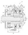
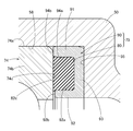
- FIG. 3 is a sectional view around a second transmission mechanism shown in FIG. 1. It is the figure which expanded the 3rd part of FIG. It is the figure which expanded the support part shown by FIG.
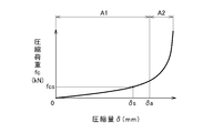
- FIG. 5 is an exploded view of the support unit shown in FIG. 4. 5 is a compression load-compression amount diagram of the elastic body shown in FIG. 4.
- FIG. It is explanatory drawing of the state which the front-end
- a vehicle steering system 10 applies a steering system 20 from a steering wheel 21 of a vehicle to wheels 31, 31 (steering wheels 31, 31) and an auxiliary torque to the steering system 20. And an auxiliary torque mechanism 40.
- the steering system 20 includes a steering wheel 21, a steering shaft 22 connected to the steering wheel 21, an input shaft 24 connected to the steering shaft 22 by a universal shaft joint 23, and a first transmission mechanism connected to the input shaft 24.
- a steering shaft 26 connected by 25, and left and right wheels (both sides in the vehicle width direction) connected to both ends of the steering shaft 26 via ball joints 27, 27, tie rods 28, 28 and knuckles 29, 29. 31, 31, and the like.
- the first transmission mechanism 25 is composed of, for example, a rack and pinion mechanism.
- the steered shaft 26 is movable in the axial direction (vehicle width direction).
- the steering torque causes the first transmission mechanism 25, the steered shaft 26, and the left and right tie rods 28, 28 to pass through the left and right wheels 31, 31. Can be steered.
- the auxiliary torque mechanism 40 includes a steering torque sensor 41, a control unit 42, an electric motor 43, and a second transmission mechanism 44.
- the steering torque sensor 41 detects the steering torque of the steering system 20 applied to the steering handle 21.
- the control unit 42 generates a control signal based on the torque detection signal of the steering torque sensor 41.
- the electric motor 43 generates a motor torque (auxiliary torque) corresponding to the steering torque, that is, a driving force, based on the control signal of the control unit 42.
- the second transmission mechanism 44 transmits the auxiliary torque generated by the electric motor 43 to the steered shaft 26.
- the wheels 31, 31 can be steered by the steered shaft 26 by the combined torque of the steering torque of the driver and the auxiliary torque of the electric motor 43.
- the first transmission mechanism 25 is housed in a housing 50 extending in the vehicle width direction.
- the steered shaft 26 is also housed in the housing 50 so as to be movable in the vehicle width direction (axial direction).
- the housing 50 is divided into a first housing half body 51 and a second housing half body 52 in the vehicle width direction, and is integrated with each other by bolt connection. ..
- the housing 50 has a storage chamber 53 at the connecting portion of the first housing half body 51 and the second housing half body 52.
- the first wall surface 54 and the second wall surface 55 that form both end surfaces of the storage chamber 53 in the vehicle width direction are flat surfaces orthogonal to the steered shaft 26.
- the first end surface 54 is provided on the first housing half body 51.
- the second end surface 55 is provided on the second housing half body 52.
- a hollow disc 56 is detachably provided in the storage chamber 53 in the vehicle width direction.
- the disc 56 has a flat side surface 57 that faces the second end surface 55 and is parallel to the second end surface 55.
- the side surface 57 will be referred to as a third end surface 57.
- the second transmission mechanism 44 is housed in the housing chamber 53.
- the second transmission mechanism 44 includes, for example, a belt transmission mechanism 60 and a ball screw 70.
- the belt transmission mechanism 60 includes a drive pulley 61 provided on the output shaft 43a of the electric motor 43, a driven pulley 62 provided on a nut 73 of a ball screw 70, and a belt wound around the drive pulley 61 and the driven pulley 62. 63 and 63.
- the ball screw 70 is a kind of conversion mechanism that converts a rotational motion into a linear motion, and a driving force generated by the electric motor 43 (see FIG. 1), that is, an auxiliary torque, is generated. It is transmitted to the steering shaft 26.
- the ball screw 70 includes a screw portion 71 formed on the steered shaft 26, a plurality of balls 72, and a nut 73 connected to the screw portion 71 via the plurality of balls 72.
- the nut 73 is rotatably supported by the housing 50 by a bearing 74 and is restricted from moving relative to the bearing 74 in the axial direction.
- the bearing 74 is located between the second end surface 55 and the third end surface 57 in the storage chamber 53, and is fitted to the inner peripheral surface 58 of the storage chamber 53. There is a very small gap between the inner peripheral surface 58 of the storage chamber 53 and the outer peripheral surface 74a of the bearing 74. Therefore, when an axial load is applied to the bearing 74, the bearing 74 is movable in the axial direction of the steered shaft 26 with respect to the inner peripheral surface 58 of the storage chamber 53.
- the bearing 74 is preferably composed of “rolling bearings” such as ball bearings and roller bearings.
- the bearing 74 will be appropriately referred to as the "rolling bearing 74".
- a pair of annular support portions 75, 75 are located on both sides of the outer ring 74b of the rolling bearing 74.
- the pair of support portions 75, 75 face each other in the axial direction of the steered shaft 26 with the rolling bearing 74 interposed therebetween.
- the rolling bearing 74 and the pair of support portions 75, 75 are located between the second end surface 55 and the third end surface 57 in the storage chamber 53.
- the side surfaces 74c, 74c of the outer ring 74b of the rolling bearing 74 are elastically supported (so-called floating support) in the axial direction of the steered shaft 26 by a pair of annular support portions 75, 75 over the entire circumference. ..
- the nut 73 is elastically supported in the axial direction of the steered shaft 26 via the bearing 74.
- the support portion 75 includes an annular elastic body 80 and an annular collar 90 that supports the elastic body 80.
- the elastic body 80 and the collar 90 are combined and integrated in the axial direction of the steered shaft 26.
- the elastic body 80 is an annular member made of an elastic material that supports the side surface 74c of the outer ring 74b of the rolling bearing 74 over the entire circumference in the axial direction of the steered shaft 26.
- the elastic material forming the elastic body 80 include a rubber single body, a resin single body, a combination product of rubber and resin, and a two-color molded product of rubber and resin.
- the elastic body 80 includes a first elastic portion 81 (base end portion 81) integrally formed with the bottom portion 93, and a second elastic portion extending from the first elastic portion 81 toward the side surface 74c of the bearing 74. It becomes the part 82 and is formed integrally.
- the first elastic portion 81 is a hollow disc-shaped portion.
- the second elastic portion 82 is an annular portion that is continuous with the first elastic portion 81.
- the cross-sectional shape of the second elastic portion 82 is a taper shape that tapers from the first elastic portion 81 toward the side surface 74c of the bearing 74. That is, both the outer peripheral surface 82a and the inner peripheral surface 82b of the second elastic portion 82 are inclined surfaces.
- the tip end surface 82c of the second elastic portion 82 (the surface 82c opposite to the first elastic portion 81) can support the side surface 74c of the bearing 74 in the axial direction of the steered shaft 26, and is flat, for example. Composed of faces.
- the inner diameter D12 of the second elastic portion 82 (the inner diameter D12 of the root of the first elastic portion 81) is larger than the inner diameter D11 of the first elastic portion 81.
- the outer diameter D13 of the second elastic portion 82 is the same as the outer diameter of the first elastic portion 81.
- the collar 90 is made of a metal material or a hard resin material, and is located between the elastic body 80 and either one of the second end surface 55 and the third end surface 57.
- the second end surface 55 and the third end surface 57 are a part of the housing 50. That is, the collar 90 is interposed between the elastic body 80 and the housing 50 in the axial direction of the steered shaft 26.
- the collar 90 is an annular member having a U-shaped cross-section that opens toward the side surface 74c of the bearing 74, and includes an outer tubular portion 91 (first tubular portion 91) on the radially outer side and the outer tubular portion 91. Also includes an inner tubular portion 92 (second tubular portion 92) radially inward, and an annular bottom portion 93 that closes between one end of the outer tubular portion 91 and one end of the inner tubular portion 92, and is integrally configured. Has been done.
- the outer cylinder part 91, the inner cylinder part 92, and the bottom part 93 are located concentrically with each other.
- the bottom portion 93 has a flat plate-like configuration, and both surfaces are flat surfaces.
- the collar 90 which has an annular shape with a U-shaped cross section, has an annular groove 94 (recessed portion 94) with a U-shaped cross section shown in FIG.
- the elastic body 80 is fitted into the groove 94.
- the radial deformation of the elastic body 80 compressed in the axial direction of the steered shaft 26 can be restricted by the outer tubular portion 91 and the inner tubular portion 92.
- the inner peripheral surface 81a of the first elastic portion 81 is in contact with the outer peripheral surface 92a of the inner cylindrical portion 92 (including elastic fitting, that is, pressure contact). That is, the inner diameter D11 of the first elastic portion 81 is set to be equal to or smaller than the outer diameter D21 of the inner tubular portion 92.
- the inner diameter D12 of the second elastic portion 82 is larger than the outer diameter D21 of the inner tubular portion 92.
- the outer diameter D13 of the second elastic portion 82 is smaller than the inner diameter D22 of the outer tubular portion 91.
- a first space S1 is provided between the outer peripheral surface 82a of the second elastic portion 82 and the inner peripheral surface 91a of the outer tubular portion 91.
- a second space S2 is provided between the inner peripheral surface 82b of the second elastic portion 82 and the outer peripheral surface 92a of the inner cylindrical portion 92.
- the first spacing C1 (the size C1 of the first space S1) between the outer peripheral surface 82a of the second elastic portion 82 and the inner peripheral surface 91a of the outer tubular portion 91 is equal to the inner peripheral surface of the second elastic portion 82. It is smaller than the second distance C2 (size C2 of the second space S2) between the outer peripheral surface 92a of the inner tubular portion 92 and the inner wall portion 82b.
- the tip end surface 91b of the outer tubular portion 91 is protruded from the bottom portion 93 more than the tip end surface 92b of the inner tubular portion 92 toward the side surface 74c of the bearing 74 by a protrusion amount X1 (see FIG. 4).
- the tip end surface 82c of the second elastic portion 82 protrudes from the tip end surface 91b of the outer tubular portion 91 toward the side surface 74c of the bearing 74 by a protrusion amount X2 (see FIG. 4).
- the elastic body 80 has a first load characteristic and a second load characteristic.
- the first load characteristic is a characteristic that the ratio of the compression load per unit compression amount that deforms in the axial direction of the steered shaft 26, that is, the spring rate gradually increases. In this first load characteristic, it is preferable that the change in spring rate is linearly approximated. Moreover, the maximum value of the spring rate in the first load characteristic is set to be small enough to reduce the vibration of the bearing 74 in the axial direction of the steered shaft 26.
- the first load characteristic is that the elastic body 80 starts to receive a compressive load from the side surface 74c of the bearing 74, and the bulging portion that is compressed and bulges in the radial direction is referred to as the outer cylinder portion 91 of the collar 90. It is a load characteristic until it is regulated by at least one of the inner cylinder portion 92.
- the second load characteristic is a characteristic in which the ratio of compression load per unit compression amount (spring rate) increases rapidly compared to the first load characteristic.
- the second load characteristic is the load characteristic after the bulging portion of the elastic body 80 is restricted by at least one of the outer cylinder portion 91 and the inner cylinder portion 92 of the collar 90.
- FIG. 6 is a compression load-compression amount diagram of the elastic body 80.
- the vertical axis is the compression load fc input to the elastic body 80
- the horizontal axis is the compression amount ⁇ of the elastic body 80.
- the characteristic of the compression amount ⁇ of 80 that is, the load characteristic is represented.
- a compression amount range A1 from the origin to a preset reference compression amount ⁇ a is referred to as a first range A1.
- the range A2 of the compression amount which is the latter half of the first range A1, is called the second range A2.
- the characteristic of the elastic body 80 has the first load characteristic of "small spring rate” and “gradual increase of spring rate” in the first range A1, and the second load “rapid increase of spring rate” in the second range A2.
- the first load characteristic the change in spring rate is linearly approximated, and the spring rate at the reference compression amount ⁇ a is maximized.
- the characteristic of the elastic body 80 has a so-called two-stage spring rate.
- the initial value ⁇ s of the compression amount ⁇ is set near the reference compression amount ⁇ a in the first range A1, that is, set small.
- the rolling bearing 74 is located between the second end surface 55 and the third end surface 57, being sandwiched by the pair of support portions 75, 75 in the axial direction of the steered shaft 26. ..
- the separation dimension Di (see FIG. 3) between the second end surface 55 and the third end surface 57 is the sum of the width of the rolling bearing 74 and the widths Wd and Wd of the pair of support portions 75 and 75 (see FIG. 4). Is set smaller than. Therefore, in the initial state in which the axial force does not act on the nut 73, the elastic bodies 80, 80 have already been compressed by a certain amount of compression (initial setting). This constant amount of compression corresponds to the initial value ⁇ s of the amount of compression ⁇ shown in FIG. 6, and is set in the first range A1. As a result, an initial compression load fcs (preload) corresponding to the initial value ⁇ s is applied to each side surface 74c, 74c of the rolling bearing 74.
- the vehicle steering system 10 includes: A steered shaft 26 housed in a housing 50 so as to be movable in the axial direction; A ball screw 70 that transmits the driving force generated by the electric motor 43 (see FIG. 1) to the steered shaft 26; A bearing 74 for rotatably supporting the nut 73 forming a part of the ball screw 70 on the housing 50;
- the steering shaft 26 has a load characteristic (first load characteristic) in which the ratio of the compressive load per unit compression amount that deforms in the axial direction gradually increases (first load characteristic), and the side surfaces 74c, 74c (rolling bearing) of the bearing 74 are provided.
- Annular elastic bodies 80, 80 made of an elastic material for supporting the side surfaces 74c, 74c of the outer ring 74b of 74 in the axial direction of the steered shaft 26 over the entire circumference, It is interposed between the elastic bodies 80, 80 and the housing 50 in the axial direction of the steered shaft 26, and has outer cylinder parts 91, 91 on the radially outer side and inner cylinder parts 92 on the radially inner side. 92 and annular bottoms 93, 93 that close between one end of the outer tubular portions 91, 91 and one end of the inner tubular portions 92, 92, facing the side surfaces 74c, 74c of the bearing 74.
- annular collars 90, 90 that can be regulated by the tubular portions 92, 92.
- the elastic body 80 has a load characteristic in which the ratio of the compression load per unit compression amount (spring rate) that deforms in the axial direction of the steered shaft 26 gradually increases. Therefore, the elastic bodies 80, 80 can exhibit a load characteristic in which the spring rate gradually increases in the so-called set state in which the elastic bodies 80, 80 are assembled.
- the outer cylinder portions 91, 91 and the inner cylinder portions 92, 92 of the collars 90, 90 can restrict the radial deformation of the elastic bodies 80, 80 compressed in the axial direction of the steered shaft 26.
- the compressed elastic bodies 80, 80 are prevented from bulging in the radial direction by the outer tubular portions 91, 91 and the inner tubular portions 92, 92, so that the spring characteristics can be changed to a load characteristic that increases rapidly. In this way, the elastic bodies 80, 80 can more reliably achieve the two-stage spring rate without changing the hardness of the material. Therefore, the necessary load characteristics of the elastic bodies 80, 80 used in the vehicle steering system 10 having the ball screw 70 can be further enhanced.
- the elastic bodies 80, 80 are incorporated in the collars 90, 90, it is possible to always maintain an appropriate posture with respect to the side surfaces 74c, 74c of the bearing 74. Since the collars 90, 90 are interposed between the housing 50 and the elastic bodies 80, 80, the collars 90, 90 are not displaced in the housing 50 in the axial direction of the steered shaft 26. Therefore, the elastic bodies 80, 80 can properly support the side surfaces 74c, 74c of the bearing 74 in the axial direction of the steered shaft 26 (so-called floating support).
- the collars 90, 90 configured in an annular shape having a U-shaped cross section have annular grooves 94, 94 (recesses 94, 94) having a U-shaped cross section.
- the elastic bodies 80, 80 are fitted into the grooves 94, 94. When the elastic bodies 80, 80 are assembled to the housing 50, there is no concern that the elastic bodies 80, 80 fall off the collars 90, 90.
- the elastic bodies 80, 80 include base end portions 81, 81 (first elastic portions 81, 81) integrally formed with the bottom portions 93, 93.
- Front end surfaces 82c and 82c for supporting the side surfaces 74c and 74c of the bearing 74 in the axial direction of the steered shaft 26 First outer spaces S1 and S1 are provided between outer peripheral surfaces 82a and 82a of the elastic bodies 80 and 80 and inner peripheral surfaces 91a and 91a of the outer tubular portions 91 and 91, respectively.
- Second gaps S2 and S2 are provided between the inner peripheral surfaces 82b and 82b of the elastic bodies 80 and 80 and the outer peripheral surfaces 92a and 92a of the inner cylindrical portions 92 and 92, respectively.
- the elastic bodies 80 and 80 are deformed in the axial direction of the steered shaft 26 and the ratio of the compression load per unit compression amount.
- the first load characteristic is that the elastic bodies 80, 80 begin to receive a compressive load from the side surfaces 74c, 74c of the bearing 74, and the bulging portion that is compressed and bulges in the radial direction is referred to as the outer tubular portion 91, It is a load characteristic until it is regulated by at least one of 91 and the inner cylinder portions 92, 92.
- the second load characteristic is a load characteristic after the bulging portion of the elastic body 80, 80 is restricted by at least one of the outer tubular portion 91, 91 and the inner tubular portion 92, 92 of the collar 90, 90. is there.
- the vibration and the operation noise caused by the displacement of the bearing 74 in the axial direction are generated by the first elastic body 80. It can be reduced depending on the load characteristics.
- the impact load acting on the bearing 74 in the axial direction can be damped by the second load characteristics of the elastic bodies 80, 80.
- the ball screw 70 and the bearing 74 can be protected from an impact load.
- the axial position of the bearing 74 with respect to the housing 50 can be maintained by the second load characteristic. As a result, it is possible to prevent tapping.
- the two-stage spring rate reduces vibration and operating noise of the bearing 74 during normal operation, and retains the position of the bearing 74 when an excessive impact load is applied to the steered shaft 26 in the axial direction. It is possible to achieve both.
- the bulging portion that bulges in the radial direction has the first gaps S1, S1 and the second gaps as shown in FIG. It is possible to swell until the voids S2, S2 of the above are eliminated. Therefore, the bulging portion does not protrude from the collars 90, 90 and are not sandwiched between the side surfaces 74c, 74c of the bearing 74 and the collars 90, 90.
- the inner peripheral surfaces 81a, 81a of the base end portions 81, 81 of the elastic bodies 80, 80 are in contact with the outer peripheral surfaces 92a, 92a of the inner cylindrical portions 92, 92. Therefore, the radial positions of the elastic bodies 80, 80 with respect to the collars 90, 90 can be accurately set, even though the first voids S1, S1 and the second voids S2, S2 are provided. You can The side surfaces 74c, 74c of the bearing 74 can be accurately supported by the elastic bodies 80, 80 over the entire circumference.
- first distances C1 and C1 between the outer peripheral surfaces 82a and 82a of the elastic bodies 80 and 80 and the inner peripheral surfaces 91a and 91a of the outer tubular portions 91 and 91 are equal to each other. It is smaller than the second intervals C2, C2 between the peripheral surfaces 82b, 82b and the outer peripheral surfaces 92a, 92a of the inner cylindrical portions 92, 92.
- the bearing 74 may have a slight inclination due to the uneven load applied to the nut 73 of the ball screw 70.
- the elastic body 80 tends to bulge outward in diameter rather than inward.
- the first distances C1 and C1 are smaller than the second distances C2 and C2. Therefore, the outward bulging of the elastic bodies 80, 80 is restricted before the outward bulging. As a result, the elastic bodies 80, 80 can be compressed and deformed substantially uniformly and efficiently.
- the cross-sectional shape of the elastic bodies 80, 80 is a taper shape that tapers from the base end portions 81, 81 toward the side surfaces 74c, 74c of the bearing 74. Since the elastic bodies 80, 80 have tapered cross-sections, it is possible to sufficiently exhibit the first load characteristic in which the spring rate gradually increases.
- the front end surfaces 91b, 91b of the outer tubular portions 91, 91 are more lateral than the front end surfaces 92b, 92b of the inner tubular portions 92, 92 to the side surfaces 74c, 74c of the bearing 74. Protruding towards. Therefore, as shown in FIG. 7, the amount of displacement of the bearing 74 in the axial direction can be accurately defined by the tip surfaces 91b and 91b of the outer cylindrical portions 91 and 91 having large diameters. Therefore, the compression amount (crush amount) of the elastic bodies 80, 80 can be regulated.
- vehicle steering system 10 is not limited to the embodiments as long as the effects and advantages of the present invention are exhibited.
- the vehicle steering system 10 mechanically separates the steering wheel 21 from the steered shaft 26, and the steering actuator (not shown) steers according to the steering amount of the steering wheel 21. It may be a so-called steer-by-wire type steering device of a system that generates the driving power and transmits the steering power to the steering shaft 26 by the ball screw 70.
- the bearing 74 is not limited to a rolling bearing, and can be constituted by a sliding bearing, for example.
- the vehicle steering system 10 of the present invention is suitable for mounting on a vehicle.
- Vehicle Steering Device 26 Steering Shaft 43 Electric Motor 50 Housing 70 Ball Screw 73 Nut 74 Bearing 74c Side of Bearing 80 Elastic Body 81 First Elastic Portion (Base End) 81a Inner peripheral surface of first elastic portion 82 Second elastic portion 82a Outer peripheral surface of second elastic portion 82b Inner peripheral surface of second elastic portion 82c Tip surface of second elastic portion 90 Collar 91 Outer tubular portion 91a Outer tubular portion Inner peripheral surface 91b End surface of outer cylindrical portion 92 Inner cylindrical portion 92a Outer peripheral surface of inner cylindrical portion 92b End surface of inner cylindrical portion 93 Bottom 94 Groove (recess) C1 Distance between first voids C2 Distance between second voids D12 Inner diameter of second elastic portion (inner diameter of elastic body) D13 Outer diameter of second elastic portion (outer diameter of elastic body) D21 Outer diameter of inner cylinder part D22 Inner diameter of outer cylinder part S1 First void S2 Second void
Landscapes
- Engineering & Computer Science (AREA)
- General Engineering & Computer Science (AREA)
- Mechanical Engineering (AREA)
- Chemical & Material Sciences (AREA)
- Combustion & Propulsion (AREA)
- Physics & Mathematics (AREA)
- Acoustics & Sound (AREA)
- Aviation & Aerospace Engineering (AREA)
- Transportation (AREA)
- Power Steering Mechanism (AREA)
- Support Of The Bearing (AREA)
- Vibration Prevention Devices (AREA)
Abstract
車両用ステアリング装置(10)は、軸方向へ移動可能にハウジング(50)に収納される転舵軸(26)と、電動モータ(43)が発生した駆動力を前記転舵軸(26)に伝達するボールねじ(70)と、前記ボールねじ(70)のナット(73)を前記ハウジング(50)に回転可能に支持する軸受(74)と、前記軸受(74)の側面(74c,74c)を全周にわたって前記転舵軸(26)の軸方向に支持する環状の弾性体(80,80)と、前記転舵軸(26)の軸方向における、前記弾性体(80,80)と前記ハウジング(50)との間に介在しており、前記軸受(74)の側面(74c,74c)に向いて開口した断面U字状に構成された環状のカラー(90,90)と、を備えている。外筒部(91,91)と内筒部(92,92)とは、前記転舵軸(26)の軸方向へ圧縮された前記弾性体(80,80)の径方向への変形を規制する。
Description
本発明は、ボールねじを有している車両用ステアリング装置に関する。
車両用ステアリング装置のなかには、電動モータが発生した駆動力を、ボールねじによって転舵軸(例えばラック軸)に伝達する形式の、いわゆる電動パワーステアリング装置がある。転舵軸が軸方向へ移動することにより、車輪を転舵することができる。この種の車両用ステアリング装置は、例えば許文献1によって知られている。
特許文献1で知られている車両用ステアリング装置は、電動モータが発生した駆動力を転舵軸に伝達するボールねじと、このボールねじの一部を成すナットをハウジングに回転可能に支持する軸受と、を備えている。この軸受の側面は、弾性体によって転舵軸の軸方向に支持(いわゆる、フローティング支持)されている。この弾性体は、ハウジングに組み付けられたセット状態では、バネレートが徐々に増大する第1荷重特性を発揮する。このため、弾性体は、ボールねじのミスアライメントや、ボールねじのナットに作用する荷重の偏りに起因して、軸受が軸方向へ変位することによる振動や作動音を、低減することができる。また、弾性体は、軸受に対して軸方向に作用する衝撃荷重を減衰する、第2荷重特性を発揮する。
しかし、弾性体は、転舵軸の軸方向へ圧縮されるにつれて、径方向へも弾性変形し得るので、上述の必要な荷重特性を、より一層高めることが求められている。
本発明は、ボールねじを有している車両用ステアリング装置に採用される弾性体の、必要な荷重特性を、より一層高めることができる技術を提供することを課題とする。
本発明によれば、車両用ステアリング装置は、
軸方向へ移動可能にハウジングに収納される転舵軸と、
電動モータが発生した駆動力を前記転舵軸に伝達するボールねじと、
前記ボールねじの一部を成すナットを前記ハウジングに回転可能に支持する軸受と、
前記転舵軸の軸方向へ変形する単位圧縮量当たりの圧縮荷重の比率が徐々に増大する荷重特性を有しており、前記軸受の側面を全周にわたって前記転舵軸の軸方向に支持する、弾性材料から成る環状の弾性体と、
前記転舵軸の軸方向における、前記弾性体と前記ハウジングとの間に介在しており、径方向外側の外筒部と、径方向内側の内筒部と、前記外筒部の一端と前記内筒部の一端との間を閉鎖している環状の底部とによって、前記軸受の側面に向いて開口した断面U字状の環状に構成されており、前記転舵軸の軸方向へ圧縮された前記弾性体の径方向への変形を、前記外筒部と前記内筒部とによって規制することが可能な構成の環状のカラーと、
を備えていることを特徴とする。
軸方向へ移動可能にハウジングに収納される転舵軸と、
電動モータが発生した駆動力を前記転舵軸に伝達するボールねじと、
前記ボールねじの一部を成すナットを前記ハウジングに回転可能に支持する軸受と、
前記転舵軸の軸方向へ変形する単位圧縮量当たりの圧縮荷重の比率が徐々に増大する荷重特性を有しており、前記軸受の側面を全周にわたって前記転舵軸の軸方向に支持する、弾性材料から成る環状の弾性体と、
前記転舵軸の軸方向における、前記弾性体と前記ハウジングとの間に介在しており、径方向外側の外筒部と、径方向内側の内筒部と、前記外筒部の一端と前記内筒部の一端との間を閉鎖している環状の底部とによって、前記軸受の側面に向いて開口した断面U字状の環状に構成されており、前記転舵軸の軸方向へ圧縮された前記弾性体の径方向への変形を、前記外筒部と前記内筒部とによって規制することが可能な構成の環状のカラーと、
を備えていることを特徴とする。
本発明では、弾性体は、転舵軸の軸方向へ変形する単位圧縮量当たりの圧縮荷重の比率(バネレート)が徐々に増大する、荷重特性を有している。このため、弾性体は、ハウジングに組み付けられた、いわゆるセットされた状態では、バネレートが徐々に増大する荷重特性を発揮することができる。カラーの外筒部と内筒部は、転舵軸の軸方向へ圧縮された弾性体の、径方向への変形を規制することができる。圧縮された弾性体は、外筒部と内筒部とによって、径方向への膨出を抑制されるので、バネレートが急増する荷重特性に、変化し得る。このように弾性体は、材料の硬度を変えることなく、2段階のバネレートを、より確実に達成することができる。従って、ボールねじを有している車両用ステアリング装置に採用される弾性体の、必要な荷重特性を、より一層高めることができる。
本発明を実施するための形態を添付図に基づいて以下に説明する。
図1に示されるように、車両用ステアリング装置10は、車両のステアリングホイール21から車輪31,31(操舵用車輪31,31)に至るステアリング系20と、このステアリング系20に補助トルクを付加する補助トルク機構40と、から成る。
ステアリング系20は、ステアリングホイール21と、このステアリングホイール21に連結されたステアリング軸22と、このステアリング軸22に自在軸継手23によって連結された入力軸24と、この入力軸24に第1伝動機構25によって連結された転舵軸26と、この転舵軸26の両端にボールジョイント27,27とタイロッド28,28とナックル29,29とを介して連結された左右(車幅方向両側)の車輪31,31と、から成る。
第1伝動機構25は、例えばラックアンドピニオン機構によって構成される。転舵軸26は、軸方向(車幅方向)へ移動可能である。
ステアリング系20によれば、運転者がステアリングホイール21を操舵することによって、操舵トルクにより第1伝動機構25と転舵軸26と左右のタイロッド28,28とを介して、左右の車輪31,31を操舵することができる。
補助トルク機構40は、操舵トルクセンサ41と制御部42と電動モータ43と第2伝動機構44とから成る。操舵トルクセンサ41は、ステアリングハンドル21に加えられたステアリング系20の操舵トルクを検出する。制御部42は、操舵トルクセンサ41のトルク検出信号に基づいて制御信号を発生する。電動モータ43は、制御部42の制御信号に基づき、前記操舵トルクに応じたモータトルク(補助トルク)、つまり駆動力を発生する。第2伝動機構44は、電動モータ43が発生した補助トルクを前記転舵軸26に伝達する。
この車両用ステアリング装置10によれば、運転者の操舵トルクに電動モータ43の補助トルクを加えた複合トルクにより、転舵軸26によって車輪31,31を転舵することができる。
第1伝動機構25は、車幅方向へ延びたハウジング50に収納されている。転舵軸26も、車幅方向(軸方向)へ移動可能にハウジング50に収納されている。
このハウジング50について、詳しく説明する。図1及び図2に示されるように、ハウジング50は、第1ハウジング半体51と第2ハウジング半体52とに、車幅方向に二分割されるとともに、互いにボルト結合によって一体化されている。
さらに、図2に示されるように、ハウジング50は、第1ハウジング半体51と第2ハウジング半体52との結合部分に、収納室53を有する。ハウジング50において、収納室53の車幅方向の両端面を形成する第1壁面54と第2壁面55は、転舵軸26に対して直交した平坦面である。第1端面54は、第1ハウジング半体51に有する。第2端面55は、第2ハウジング半体52に有する。収納室53のなかの、車幅方向の途中には、中空状の円板56が着脱可能に設けられている。この円板56は、第2端面55に対して対向し且つ平行な平坦な側面57を有する。この側面57のことを、以下、第3端面57ということにする。
図1及び図2に示されるように、第2伝動機構44は収納室53に収納されている。この第2伝動機構44は、例えばベルト伝動機構60とボールねじ70とから成る。ベルト伝動機構60は、電動モータ43の出力軸43aに設けられた駆動プーリ61と、ボールねじ70のナット73に設けられた従動プーリ62と、駆動プーリ61と従動プーリ62とに掛けられたベルト63とから成る。
図2及び図3に示されるように、ボールねじ70は、回転運動を直線運動に変換する変換機構の一種であって、電動モータ43(図1参照)が発生した駆動力、つまり補助トルクを前記転舵軸26に伝達する。このボールねじ70は、転舵軸26に形成されたネジ部71と、複数のボール72と、ネジ部71に複数のボール72を介して連結されたナット73とから成る。
ナット73は、軸受74によってハウジング50に回転可能に支持されるとともに、軸受74に対して軸方向への相対移動を規制されている。この軸受74は、収納室53のなかの、第2端面55と第3端面57との間に位置するとともに、収納室53の内周面58に嵌合している。収納室53の内周面58と軸受74の外周面74aとの間には、極く微小な隙間が有る。このため、軸受74に対して軸方向への荷重が作用した場合に、軸受74は、収納室53の内周面58に対して、転舵軸26の軸方向へ移動可能である。
軸受74は、ボールベアリングやローラベアリングなどの「転がり軸受」によって構成されることが好ましい。以下、軸受74のことを、適宜「転がり軸受74」と言い換える。転がり軸受74の外輪74bの両側には、一対の環状の支持部75,75が位置している。この一対の支持部75,75同士は、転がり軸受74を挟んで、転舵軸26の軸方向に互いに向かい合っている。このように、収納室53のなかの、第2端面55と第3端面57との間には、転がり軸受74と一対の支持部75,75が位置している。転がり軸受74の外輪74bの側面74c,74cは、全周にわたり、一対の環状の支持部75,75によって転舵軸26の軸方向に弾性を有して支持(いわゆる、フローティング支持)されている。この結果、ナット73は、軸受74を介して間接的に、転舵軸26の軸方向に弾性を有して支持されている。
以下、図3~図5を参照しつつ、一対の支持部75,75のなかの、1つの支持部75を代表して説明する。支持部75は、環状の弾性体80と、この弾性体80を支持する環状のカラー90と、から成る。弾性体80とカラー90とは、転舵軸26の軸方向に互いに組み合わされて、一体化されている。
弾性体80は、転がり軸受74の外輪74bの側面74cを全周にわたって転舵軸26の軸方向に支持する、弾性材料から成る環状の部材である。この弾性体80を構成する弾性材料としては、例えばラバー単体、樹脂単体、ラバーと樹脂との組み合わせ品、ラバーと樹脂の二色成形品がある。
詳しく説明すると、弾性体80は、底部93に一体に構成される第1弾性部81(基端部81)と、この第1弾性部81から軸受74の側面74cへ向かって延びた第2弾性部82と成り、一体に形成されて成る。第1弾性部81は、中空円盤状の部分である。第2弾性部82は、第1弾性部81に連なる環状の部分である。この第2弾性部82の断面形状は、第1弾性部81から軸受74の側面74cへ向かって先細りとなるテーパ状である。つまり、第2弾性部82は外周面82aと内周面82bの両方が傾斜面である。第2弾性部82の先端面82c(第1弾性部81に対して反対側の面82c)は、軸受74の側面74cを転舵軸26の軸方向に支持することが可能であり、例えば平坦面から成る。第2弾性部82の内径D12(第1弾性部81に対する付け根の内径D12)は、第1弾性部81の内径D11よりも大きい。第2弾性部82の外径D13は、第1弾性部81の外径と同じである。
カラー90は、金属材料や硬質樹脂材料から成り、第2端面55と第3端面57のいずれか一方と、弾性体80との間に位置している。第2端面55と第3端面57は、ハウジング50の一部である。つまり、カラー90は、転舵軸26の軸方向における、弾性体80とハウジング50との間に介在している。
このカラー90は、軸受74の側面74cに向いて開口した断面U字状の環状の部材であって、径方向外側の外筒部91(第1筒部91)と、この外筒部91よりも径方向内側の内筒部92(第2筒部92)と、外筒部91の一端と内筒部92の一端との間を閉鎖している環状の底部93とから成り、一体に構成されている。外筒部91と内筒部92と底部93とは、互いに同心上に位置している。底部93は平板状の構成であって、両面が平坦面である。
断面U字状の環状に構成されているカラー90は、図5に示される断面U字状の環状の溝94(凹部94)を有することになる。弾性体80は溝94に嵌め込まれる。転舵軸26の軸方向へ圧縮された弾性体80の径方向への変形を、外筒部91と内筒部92とによって規制することが可能である。
第1弾性部81の内周面81aは、内筒部92の外周面92aに接している(弾性を有した嵌合、つまり圧接を含む)。つまり、第1弾性部81の内径D11は、内筒部92の外径D21と同一、又はそれ以下に設定されている。
第2弾性部82の内径D12は、内筒部92の外径D21よりも大きい。第2弾性部82の外径D13は、外筒部91の内径D22よりも小さい。第2弾性部82の外周面82aと外筒部91の内周面91aとの間には、第1の空隙S1を有する。第2弾性部82の内周面82bと内筒部92の外周面92aとの間には、第2の空隙S2を有する。第2弾性部82の外周面82aと外筒部91の内周面91aとの間の第1の間隔C1(第1の空隙S1の大きさC1)は、第2弾性部82の内周面82bと内筒部92の外周面92aとの間の第2の間隔C2(第2の空隙S2の大きさC2)よりも小さい。
底部93に対して、外筒部91の先端面91bは、内筒部92の先端面92bよりも、軸受74の側面74cへ向かって突出量X1(図4参照)だけ突出している。第2弾性部82の先端面82cは、外筒部91の先端面91bから、軸受74の側面74cへ向かって突出量X2(図4参照)だけ突出している。
弾性体80は、第1荷重特性と第2荷重特性とを有している。
第1荷重特性は、転舵軸26の軸方向へ変形する単位圧縮量当たりの圧縮荷重の比率、つまりバネレートが徐々に増大する特性である。この第1荷重特性では、バネレートの変化は線形に近似していることが好ましい。しかも、この第1荷重特性でのバネレートの最大値は、転舵軸26の軸方向への、軸受74の振動を低減することが可能な程度に、小さく設定されている。具体的には、この第1荷重特性は、弾性体80が軸受74の側面74cから圧縮荷重を受け始め、圧縮されて径方向へ膨出した膨出部分を、カラー90の外筒部91と内筒部92との少なくとも一方により規制されるまでの、荷重特性である。
第2荷重特性は、単位圧縮量当たりの圧縮荷重の比率(バネレート)が、第1荷重特性に比べて急増する特性である。具体的には、第2荷重特性は、弾性体80の前記膨出部分が、カラー90の外筒部91と内筒部92との少なくとも一方によって規制された後の、荷重特性である。
ここで、弾性体80の荷重特性について、図6を参照しつつ説明する。図6は、弾性体80の圧縮荷重-圧縮量線図であり、縦軸を弾性体80に入力する圧縮荷重fcとし、横軸を弾性体80の圧縮量δとして、圧縮荷重fcに対する弾性体80の圧縮量δの特性、つまり荷重特性を表している。原点から予め設定された基準圧縮量δaまでの、圧縮量の範囲A1のことを、第1の範囲A1という。第1の範囲A1よりも後半の、圧縮量の範囲A2のことを、第2の範囲A2という。
弾性体80の特性は、第1の範囲A1では「バネレートが小さく」且つ「バネレートが徐々に増大する」第1荷重特性を有し、第2の範囲A2では「バネレートが急増する」第2荷重特性を有する。第1荷重特性では、バネレートの変化が線形に近似しているとともに、基準圧縮量δaでのバネレートが最大となる。このように弾性体80の特性は、いわゆる2段階のバネレートを有している。本発明では、圧縮量δの初期値δsは、第1の範囲A1において基準圧縮量δaの近くに設定、つまり小さく設定されている。
次に、一対の支持部75,75の作用を説明する。図3に示されるように、転がり軸受74は、一対の支持部75,75によって転舵軸26の軸方向に挟み込まれて、第2端面55と第3端面57との間に位置している。
第2端面55と第3端面57との間の離間寸法Di(図3参照)は、転がり軸受74の幅と一対の支持部75,75の各幅Wd,Wd(図4参照)との総和よりも、小さく設定されている。このため、軸方向の力がナット73に作用していない初期状態において、既に弾性体80,80は、一定の圧縮量だけ圧縮されている(初期設定されている)。この一定の圧縮量は、図6に示される圧縮量δの初期値δsに相当し、第1の範囲A1に設定される。この結果、初期値δsに対応した初期圧縮荷重fcs(予圧)が、転がり軸受74の各側面74c,74cに付与される。この初期状態では、図3に示されるように、転がり軸受74の各側面74c,74cと各カラー90,90の先端面91a,91aとの間には、転舵軸26の軸方向に一定の隙間Sp,Spを有している。ナット73や転がり軸受74に作用した、軸方向の力は、弾性体80,80によって減衰される。
ナット73や転がり軸受74に作用した軸方向の力が過大になると、図6に示されるように、転がり軸受74の側面74cが軸方向へ変位して、カラー90の外筒部91の先端面91bに当たる。転がり軸受74はこれ以上の変位を規制される。弾性体80は、これ以上の弾性変形をしない。この場合に、弾性体80は、外筒部91と内筒部92とによって径方向への膨出を規制されるので、径方向へ膨出して、転がり軸受74の側面74cとカラー90との間に挟み込まれることはない。
以上の説明をまとめると、次の通りである。
図2及び図3に示されるように、車両用ステアリング装置10は、
軸方向へ移動可能にハウジング50に収納される転舵軸26と、
電動モータ43(図1参照)が発生した駆動力を前記転舵軸26に伝達するボールねじ70と、
前記ボールねじ70の一部を成すナット73を前記ハウジング50に回転可能に支持する軸受74と、
前記転舵軸26の軸方向へ変形する単位圧縮量当たりの圧縮荷重の比率が徐々に増大する荷重特性(第1荷重特性)を有しており、前記軸受74の側面74c,74c(転がり軸受74の外輪74bの側面74c,74c)を全周にわたって前記転舵軸26の軸方向に支持する、弾性材料から成る環状の弾性体80,80と、
前記転舵軸26の軸方向における、前記弾性体80,80と前記ハウジング50との間に介在しており、径方向外側の外筒部91,91と、径方向内側の内筒部92,92と、前記外筒部91,91の一端と前記内筒部92,92の一端との間を閉鎖している環状の底部93,93とによって、前記軸受74の側面74c,74cに向いて開口した断面U字状の環状に構成されており、前記転舵軸26の軸方向へ圧縮された前記弾性体80,80の径方向への変形を、前記外筒部91,91と前記内筒部92,92とによって規制することが可能な構成の環状のカラー90,90と、を備えている。
図2及び図3に示されるように、車両用ステアリング装置10は、
軸方向へ移動可能にハウジング50に収納される転舵軸26と、
電動モータ43(図1参照)が発生した駆動力を前記転舵軸26に伝達するボールねじ70と、
前記ボールねじ70の一部を成すナット73を前記ハウジング50に回転可能に支持する軸受74と、
前記転舵軸26の軸方向へ変形する単位圧縮量当たりの圧縮荷重の比率が徐々に増大する荷重特性(第1荷重特性)を有しており、前記軸受74の側面74c,74c(転がり軸受74の外輪74bの側面74c,74c)を全周にわたって前記転舵軸26の軸方向に支持する、弾性材料から成る環状の弾性体80,80と、
前記転舵軸26の軸方向における、前記弾性体80,80と前記ハウジング50との間に介在しており、径方向外側の外筒部91,91と、径方向内側の内筒部92,92と、前記外筒部91,91の一端と前記内筒部92,92の一端との間を閉鎖している環状の底部93,93とによって、前記軸受74の側面74c,74cに向いて開口した断面U字状の環状に構成されており、前記転舵軸26の軸方向へ圧縮された前記弾性体80,80の径方向への変形を、前記外筒部91,91と前記内筒部92,92とによって規制することが可能な構成の環状のカラー90,90と、を備えている。
弾性体80は、転舵軸26の軸方向へ変形する単位圧縮量当たりの圧縮荷重の比率(バネレート)が徐々に増大する、荷重特性を有している。このため、弾性体80,80は、ハウジング50に組み付けられた、いわゆるセットされた状態では、バネレートが徐々に増大する荷重特性を発揮することができる。カラー90,90の外筒部91,91と内筒部92,92は、転舵軸26の軸方向へ圧縮された弾性体80,80の、径方向への変形を規制することができる。圧縮された弾性体80,80は、外筒部91,91と内筒部92,92とによって、径方向への膨出を抑制されるので、バネレートが急増する荷重特性に、変化し得る。このように弾性体80,80は、材料の硬度を変えることなく、2段階のバネレートを、より確実に達成することができる。従って、ボールねじ70を有している車両用ステアリング装置10に採用される弾性体80,80の、必要な荷重特性を、より一層高めることができる。
しかも、弾性体80,80は、カラー90,90に組み込まれているので、軸受74の側面74c,74cに対して常に適切な姿勢を維持することができる。カラー90,90は、ハウジング50と弾性体80,80との間に介在しているので、ハウジング50内で転舵軸26の軸方向へ変位しない。このため、弾性体80,80によって、軸受74の側面74c,74cを転舵軸26の軸方向に適切に支持(いわゆる、フローティング支持)することができる。
また、断面U字状の環状に構成されているカラー90,90は、断面U字状の環状の溝94,94(凹部94,94)を有することになる。この溝94,94に弾性体80,80が嵌め込まれる。ハウジング50に弾性体80,80を組み付ける際に、弾性体80,80がカラー90,90から脱落する心配はない。
さらに、図3及び図4に示されるように、前記弾性体80,80は、前記底部93,93に一体に構成される基端部81,81(第1弾性部81,81)と、前記軸受74の側面74c,74cを前記転舵軸26の軸方向に支持する先端面82c,82cと、を有し、
前記弾性体80,80の外周面82a,82aと前記外筒部91,91の内周面91a,91aとの間には第1の空隙S1,S1を有し、
前記弾性体80,80の内周面82b,82bと前記内筒部92,92の外周面92a,92aとの間には第2の空隙S2,S2を有している。
前記弾性体80,80の外周面82a,82aと前記外筒部91,91の内周面91a,91aとの間には第1の空隙S1,S1を有し、
前記弾性体80,80の内周面82b,82bと前記内筒部92,92の外周面92a,92aとの間には第2の空隙S2,S2を有している。
このように、第1の空隙S1,S1及び第2の空隙S2,S2を有することにより、弾性体80,80は、転舵軸26の軸方向へ変形する単位圧縮量当たりの圧縮荷重の比率が徐々に増大する第1荷重特性と、前記比率が第1荷重特性に比べて急増する第2荷重特性との、いわゆる2段階のバネレートを有することができる。
第1荷重特性は、弾性体80,80が軸受74の側面74c,74cから圧縮荷重を受け始め、圧縮されて径方向へ膨出した膨出部分を、カラー90,90の外筒部91,91と内筒部92,92との少なくとも一方により規制されるまでの、荷重特性である。第2荷重特性は、弾性体80,80の前記膨出部分が、カラー90,90の外筒部91,91と内筒部92,92との少なくとも一方によって規制された後の、荷重特性である。
このため、ボールねじ70のミスアライメントや、ボールねじ70のナット73に作用する荷重の偏りに起因して、軸受74が軸方向へ変位することによる振動や作動音を、弾性体80の第1荷重特性によって低減することができる。
また、軸受74に対して軸方向に作用する衝撃荷重を、弾性体80,80の第2荷重特性によって減衰することができる。この結果、ボールねじ70や軸受74を衝撃荷重から保護することができる。加えて、ハウジング50に対する軸受74の、軸方向の位置を、第2荷重特性によって保持することができる。この結果、打音の発生を防止することができる。
このように、2段階のバネレートによって、通常運転時における軸受74の振動や作動音の低減と、転舵軸26に軸方向の過大な衝撃荷重を受けたときの軸受74の位置の保持性との、両立を図ることができる。
しかも、弾性体80,80が転舵軸26の軸方向へ圧縮されるにつれて、径方向へ膨出した膨出部分は、図7に示されるように、第1の空隙S1,S1や第2の空隙S2,S2が無くなるまで、膨出することができる。このため、膨出部分がカラー90,90から、はみ出して、軸受74の側面74c,74cとカラー90,90との間に挟み込まれることはない。
さらに、前記弾性体80,80の前記基端部81,81の内周面81a、81aは、前記内筒部92,92の外周面92a,92aに接している。このため、第1の空隙S1,S1及び第2の空隙S2,S2を有しているにもかかわらず、カラー90,90に対する弾性体80,80の径方向の位置を、正確に設定することができる。軸受74の側面74c,74cを全周にわたり、弾性体80,80によって正確に支持することができる。しかも、弾性体80,80の基端部81,81の内周面81a,81aのみが、内筒部92,92の外周面92a,92aに接するので、圧縮された弾性体80,80が径方向へ膨出する作用に、影響を及ぼすことはない。
さらに、前記弾性体80,80の外周面82a,82aと前記外筒部91,91の内周面91a,91aとの間の第1の間隔C1,C1は、前記弾性体80,80の内周面82b,82bと前記内筒部92,92の外周面92a,92aとの間の第2の間隔C2,C2よりも小さい。
上述のように、ボールねじ70のナット73に作用する荷重の偏りに起因して、軸受74には微小な傾きが発生し得る。この場合に、弾性体80は、径内方よりも径外方へ膨出する傾向になる。これに対し、第1の間隔C1,C1は、第2の間隔C2,C2よりも小さい。このため、弾性体80,80の径外方への膨出は、径内方への膨出よりも先に規制される。この結果、弾性体80,80を、概ね均等に効率よく圧縮変形させることができる。
さらに、前記弾性体80,80の断面形状は、前記基端部81,81から前記軸受74の側面74c,74cへ向かって先細りとなるテーパ状である。弾性体80,80の断面形状が先細りテーパ状であるから、バネレートが徐々に増大する第1荷重特性を、十分に発揮することができる。
さらに、前記底部93,93に対して、前記外筒部91,91の先端面91b,91bは、前記内筒部92,92の先端面92b,92bよりも、前記軸受74の側面74c,74cへ向かって突出している。このため、図7に示されるように、軸受74が軸方向へ変位する変位量を、大径である外筒部91,91の先端面91b,91bによって、正確に規定することができる。従って、弾性体80,80の圧縮量(潰れ量)を規制することができる。
なお、本発明による車両用ステアリング装置10は、本発明の作用及び効果を奏する限りにおいて、実施例に限定されるものではない。
例えば、本発明では、車両用ステアリング装置10は、ステアリングホイール21と転舵軸26との間を機械的に分離し、ステアリングホイール21の操舵量に従って転舵用アクチュエータ(図示せず)が転舵用動力を発生し、この転舵用動力をボールねじ70によって転舵軸26に伝える方式の、いわゆる、ステア バイ ワイヤ(steer-by-wire)式ステアリング装置であってもよい。
また、軸受74は、転がり軸受に限定されるものではなく、例えば滑り軸受によって構成することができる。
本発明の車両用ステアリング装置10は、自動車に搭載するのに好適である。
10 車両用ステアリング装置
26 転舵軸
43 電動モータ
50 ハウジング
70 ボールねじ
73 ナット
74 軸受
74c 軸受の側面
80 弾性体
81 第1弾性部(基端部)
81a 第1弾性部の内周面
82 第2弾性部
82a 第2弾性部の外周面
82b 第2弾性部の内周面
82c 第2弾性部の先端面
90 カラー
91 外筒部
91a 外筒部の内周面
91b 外筒部の先端面
92 内筒部
92a 内筒部の外周面
92b 内筒部の先端面
93 底部
94 溝(凹部)
C1 第1の空隙の間隔
C2 第2の空隙の間隔
D12 第2弾性部の内径(弾性体の内径)
D13 第2弾性部の外径(弾性体の外径)
D21 内筒部の外径
D22 外筒部の内径
S1 第1の空隙
S2 第2の空隙
26 転舵軸
43 電動モータ
50 ハウジング
70 ボールねじ
73 ナット
74 軸受
74c 軸受の側面
80 弾性体
81 第1弾性部(基端部)
81a 第1弾性部の内周面
82 第2弾性部
82a 第2弾性部の外周面
82b 第2弾性部の内周面
82c 第2弾性部の先端面
90 カラー
91 外筒部
91a 外筒部の内周面
91b 外筒部の先端面
92 内筒部
92a 内筒部の外周面
92b 内筒部の先端面
93 底部
94 溝(凹部)
C1 第1の空隙の間隔
C2 第2の空隙の間隔
D12 第2弾性部の内径(弾性体の内径)
D13 第2弾性部の外径(弾性体の外径)
D21 内筒部の外径
D22 外筒部の内径
S1 第1の空隙
S2 第2の空隙
Claims (6)
- 軸方向へ移動可能にハウジングに収納される転舵軸と、
電動モータが発生した駆動力を前記転舵軸に伝達するボールねじと、
前記ボールねじの一部を成すナットを前記ハウジングに回転可能に支持する軸受と、
前記転舵軸の軸方向へ変形する単位圧縮量当たりの圧縮荷重の比率が徐々に増大する荷重特性を有しており、前記軸受の側面を全周にわたって前記転舵軸の軸方向に支持する、弾性材料から成る環状の弾性体と、
前記転舵軸の軸方向における、前記弾性体と前記ハウジングとの間に介在しており、径方向外側の外筒部と、径方向内側の内筒部と、前記外筒部の一端と前記内筒部の一端との間を閉鎖している環状の底部とによって、前記軸受の側面に向いて開口した断面U字状の環状に構成されており、前記転舵軸の軸方向へ圧縮された前記弾性体の径方向への変形を、前記外筒部と前記内筒部とによって規制することが可能な構成の環状のカラーと、
を備えていることを特徴とする車両用ステアリング装置。 - 前記弾性体は、前記底部に一体に構成される基端部と、前記軸受の側面を前記転舵軸の軸方向に支持する先端面と、を有し、
前記弾性体の外周面と前記外筒部の内周面との間には第1の空隙を有し、
前記弾性体の内周面と前記内筒部の外周面との間には第2の空隙を有している、
ことを特徴とする請求項1に記載の車両用ステアリング装置。 - 前記弾性体の前記基端部の内周面は、前記内筒部の外周面に接している、
ことを特徴とする請求項2に記載の車両用ステアリング装置。 - 前記弾性体の外周面と前記外筒部の内周面との間の第1の間隔は、前記弾性体の内周面と前記内筒部の外周面との間の第2の間隔よりも小さい、
ことを特徴とする請求項2又は請求項3に記載の車両用ステアリング装置。 - 前記弾性体の断面形状は、前記基端部から前記軸受の側面へ向かって先細りとなるテーパ状である、
ことを特徴とする請求項2~4のいずれか1項に記載の車両用ステアリング装置。 - 前記外筒部の先端面は、前記内筒部の先端面よりも前記軸受の側面へ向かって突出している、
ことを特徴とする請求項1~5のいずれか1項に記載の車両用ステアリング装置。
Priority Applications (2)
| Application Number | Priority Date | Filing Date | Title |
|---|---|---|---|
| PCT/JP2019/006749 WO2020170417A1 (ja) | 2019-02-22 | 2019-02-22 | 車両用ステアリング装置 |
| JP2019510984A JP6608563B1 (ja) | 2019-02-22 | 2019-02-22 | 車両用ステアリング装置 |
Applications Claiming Priority (1)
| Application Number | Priority Date | Filing Date | Title |
|---|---|---|---|
| PCT/JP2019/006749 WO2020170417A1 (ja) | 2019-02-22 | 2019-02-22 | 車両用ステアリング装置 |
Publications (1)
| Publication Number | Publication Date |
|---|---|
| WO2020170417A1 true WO2020170417A1 (ja) | 2020-08-27 |
Family
ID=68611056
Family Applications (1)
| Application Number | Title | Priority Date | Filing Date |
|---|---|---|---|
| PCT/JP2019/006749 Ceased WO2020170417A1 (ja) | 2019-02-22 | 2019-02-22 | 車両用ステアリング装置 |
Country Status (2)
| Country | Link |
|---|---|
| JP (1) | JP6608563B1 (ja) |
| WO (1) | WO2020170417A1 (ja) |
Cited By (1)
| Publication number | Priority date | Publication date | Assignee | Title |
|---|---|---|---|---|
| US12560236B2 (en) | 2024-06-20 | 2026-02-24 | Borgwarner Inc. | Bearing spacer |
Citations (5)
| Publication number | Priority date | Publication date | Assignee | Title |
|---|---|---|---|---|
| JP2013119322A (ja) * | 2011-12-07 | 2013-06-17 | Jtekt Corp | 電動パワーステアリング装置 |
| JP2013147074A (ja) * | 2012-01-17 | 2013-08-01 | Jtekt Corp | 電動パワーステアリング装置 |
| JP2014166790A (ja) * | 2013-02-28 | 2014-09-11 | Jtekt Corp | 電動パワーステアリング装置 |
| JP2016159668A (ja) * | 2015-02-27 | 2016-09-05 | 株式会社ショーワ | 車両用転舵装置 |
| JP6266182B1 (ja) * | 2017-06-29 | 2018-01-24 | 株式会社ショーワ | 車両用ステアリング装置 |
-
2019
- 2019-02-22 JP JP2019510984A patent/JP6608563B1/ja active Active
- 2019-02-22 WO PCT/JP2019/006749 patent/WO2020170417A1/ja not_active Ceased
Patent Citations (5)
| Publication number | Priority date | Publication date | Assignee | Title |
|---|---|---|---|---|
| JP2013119322A (ja) * | 2011-12-07 | 2013-06-17 | Jtekt Corp | 電動パワーステアリング装置 |
| JP2013147074A (ja) * | 2012-01-17 | 2013-08-01 | Jtekt Corp | 電動パワーステアリング装置 |
| JP2014166790A (ja) * | 2013-02-28 | 2014-09-11 | Jtekt Corp | 電動パワーステアリング装置 |
| JP2016159668A (ja) * | 2015-02-27 | 2016-09-05 | 株式会社ショーワ | 車両用転舵装置 |
| JP6266182B1 (ja) * | 2017-06-29 | 2018-01-24 | 株式会社ショーワ | 車両用ステアリング装置 |
Cited By (1)
| Publication number | Priority date | Publication date | Assignee | Title |
|---|---|---|---|---|
| US12560236B2 (en) | 2024-06-20 | 2026-02-24 | Borgwarner Inc. | Bearing spacer |
Also Published As
| Publication number | Publication date |
|---|---|
| JP6608563B1 (ja) | 2019-11-20 |
| JPWO2020170417A1 (ja) | 2021-03-18 |
Similar Documents
| Publication | Publication Date | Title |
|---|---|---|
| JP6266182B1 (ja) | 車両用ステアリング装置 | |
| JP5641195B2 (ja) | 電動パワーステアリング装置 | |
| CN103857581B (zh) | 转向盘的电动位置调节装置 | |
| CN102216144B (zh) | 具有隔离器的将旋转运动变换成线性运动的机构 | |
| US9302697B2 (en) | Steering apparatus | |
| US7461571B2 (en) | Vehicle steering apparatus | |
| JPWO2004052712A1 (ja) | 電動パワーステアリング装置 | |
| JP5417840B2 (ja) | ステアリング装置 | |
| JP2013189112A (ja) | 電動パワーステアリング装置 | |
| JP6768181B1 (ja) | 車両用ステアリング装置 | |
| KR102106287B1 (ko) | 스티어 바이 와이어식 동력 보조 조향장치 | |
| JP2016003760A (ja) | ウォーム減速機およびそれを備えた電動パワーステアリング装置 | |
| WO2020170417A1 (ja) | 車両用ステアリング装置 | |
| KR101034099B1 (ko) | 전동식 동력조향장치의 웜 기어축 지지장치 | |
| US9296414B2 (en) | Electric power steering apparatus | |
| JP5245534B2 (ja) | 伸縮軸及び伸縮軸を備えたステアリング装置 | |
| JP5157410B2 (ja) | 伸縮軸及び伸縮軸を備えたステアリング装置 | |
| JP4622638B2 (ja) | ラックピニオン式ステアリングギヤ | |
| JP2007203947A (ja) | 電動式パワーステアリング装置用ウォーム減速機及びこれを組み込んだ電動式パワーステアリング装置 | |
| JP5157506B2 (ja) | 伸縮軸 | |
| JP2009180322A (ja) | 伸縮軸及び伸縮軸を備えたステアリング装置 | |
| JP5056182B2 (ja) | テレスコピック式ステアリング装置 | |
| JP2015107683A (ja) | ラックシャフト支持装置およびこの装置を備えるステアリング装置 | |
| JP2019119274A (ja) | ステアリング装置 | |
| JP4899706B2 (ja) | 十字軸自在継手 |
Legal Events
| Date | Code | Title | Description |
|---|---|---|---|
| ENP | Entry into the national phase |
Ref document number: 2019510984 Country of ref document: JP Kind code of ref document: A |
|
| 121 | Ep: the epo has been informed by wipo that ep was designated in this application |
Ref document number: 19915746 Country of ref document: EP Kind code of ref document: A1 |
|
| NENP | Non-entry into the national phase |
Ref country code: DE |
|
| 122 | Ep: pct application non-entry in european phase |
Ref document number: 19915746 Country of ref document: EP Kind code of ref document: A1 |