WO2020166549A1 - Procédé d'évaluation de code bidimensionnel dynamique, système d'évaluation de code bidimensionnel dynamique et programme d'évaluation de code bidimensionnel dynamique - Google Patents
Procédé d'évaluation de code bidimensionnel dynamique, système d'évaluation de code bidimensionnel dynamique et programme d'évaluation de code bidimensionnel dynamique Download PDFInfo
- Publication number
- WO2020166549A1 WO2020166549A1 PCT/JP2020/005090 JP2020005090W WO2020166549A1 WO 2020166549 A1 WO2020166549 A1 WO 2020166549A1 JP 2020005090 W JP2020005090 W JP 2020005090W WO 2020166549 A1 WO2020166549 A1 WO 2020166549A1
- Authority
- WO
- WIPO (PCT)
- Prior art keywords
- dimensional code
- evaluation
- information
- code
- dimensional
- Prior art date
Links
Images


Classifications
-
- G—PHYSICS
- G06—COMPUTING; CALCULATING OR COUNTING
- G06K—GRAPHICAL DATA READING; PRESENTATION OF DATA; RECORD CARRIERS; HANDLING RECORD CARRIERS
- G06K7/00—Methods or arrangements for sensing record carriers, e.g. for reading patterns
- G06K7/10—Methods or arrangements for sensing record carriers, e.g. for reading patterns by electromagnetic radiation, e.g. optical sensing; by corpuscular radiation
- G06K7/14—Methods or arrangements for sensing record carriers, e.g. for reading patterns by electromagnetic radiation, e.g. optical sensing; by corpuscular radiation using light without selection of wavelength, e.g. sensing reflected white light
- G06K7/1404—Methods for optical code recognition
- G06K7/1408—Methods for optical code recognition the method being specifically adapted for the type of code
- G06K7/1417—2D bar codes
-
- G—PHYSICS
- G06—COMPUTING; CALCULATING OR COUNTING
- G06K—GRAPHICAL DATA READING; PRESENTATION OF DATA; RECORD CARRIERS; HANDLING RECORD CARRIERS
- G06K19/00—Record carriers for use with machines and with at least a part designed to carry digital markings
- G06K19/06—Record carriers for use with machines and with at least a part designed to carry digital markings characterised by the kind of the digital marking, e.g. shape, nature, code
- G06K19/06009—Record carriers for use with machines and with at least a part designed to carry digital markings characterised by the kind of the digital marking, e.g. shape, nature, code with optically detectable marking
- G06K19/06037—Record carriers for use with machines and with at least a part designed to carry digital markings characterised by the kind of the digital marking, e.g. shape, nature, code with optically detectable marking multi-dimensional coding
-
- G—PHYSICS
- G06—COMPUTING; CALCULATING OR COUNTING
- G06K—GRAPHICAL DATA READING; PRESENTATION OF DATA; RECORD CARRIERS; HANDLING RECORD CARRIERS
- G06K7/00—Methods or arrangements for sensing record carriers, e.g. for reading patterns
- G06K7/10—Methods or arrangements for sensing record carriers, e.g. for reading patterns by electromagnetic radiation, e.g. optical sensing; by corpuscular radiation
- G06K7/10544—Methods or arrangements for sensing record carriers, e.g. for reading patterns by electromagnetic radiation, e.g. optical sensing; by corpuscular radiation by scanning of the records by radiation in the optical part of the electromagnetic spectrum
- G06K7/10821—Methods or arrangements for sensing record carriers, e.g. for reading patterns by electromagnetic radiation, e.g. optical sensing; by corpuscular radiation by scanning of the records by radiation in the optical part of the electromagnetic spectrum further details of bar or optical code scanning devices
- G06K7/1095—Methods or arrangements for sensing record carriers, e.g. for reading patterns by electromagnetic radiation, e.g. optical sensing; by corpuscular radiation by scanning of the records by radiation in the optical part of the electromagnetic spectrum further details of bar or optical code scanning devices the scanner comprising adaptations for scanning a record carrier that is displayed on a display-screen or the like
-
- G—PHYSICS
- G06—COMPUTING; CALCULATING OR COUNTING
- G06K—GRAPHICAL DATA READING; PRESENTATION OF DATA; RECORD CARRIERS; HANDLING RECORD CARRIERS
- G06K7/00—Methods or arrangements for sensing record carriers, e.g. for reading patterns
- G06K7/10—Methods or arrangements for sensing record carriers, e.g. for reading patterns by electromagnetic radiation, e.g. optical sensing; by corpuscular radiation
- G06K7/14—Methods or arrangements for sensing record carriers, e.g. for reading patterns by electromagnetic radiation, e.g. optical sensing; by corpuscular radiation using light without selection of wavelength, e.g. sensing reflected white light
- G06K7/1404—Methods for optical code recognition
- G06K7/1439—Methods for optical code recognition including a method step for retrieval of the optical code
- G06K7/1443—Methods for optical code recognition including a method step for retrieval of the optical code locating of the code in an image
-
- G—PHYSICS
- G06—COMPUTING; CALCULATING OR COUNTING
- G06K—GRAPHICAL DATA READING; PRESENTATION OF DATA; RECORD CARRIERS; HANDLING RECORD CARRIERS
- G06K7/00—Methods or arrangements for sensing record carriers, e.g. for reading patterns
- G06K7/10—Methods or arrangements for sensing record carriers, e.g. for reading patterns by electromagnetic radiation, e.g. optical sensing; by corpuscular radiation
- G06K7/14—Methods or arrangements for sensing record carriers, e.g. for reading patterns by electromagnetic radiation, e.g. optical sensing; by corpuscular radiation using light without selection of wavelength, e.g. sensing reflected white light
- G06K7/1404—Methods for optical code recognition
- G06K7/1439—Methods for optical code recognition including a method step for retrieval of the optical code
- G06K7/1447—Methods for optical code recognition including a method step for retrieval of the optical code extracting optical codes from image or text carrying said optical code
-
- G—PHYSICS
- G06—COMPUTING; CALCULATING OR COUNTING
- G06K—GRAPHICAL DATA READING; PRESENTATION OF DATA; RECORD CARRIERS; HANDLING RECORD CARRIERS
- G06K7/00—Methods or arrangements for sensing record carriers, e.g. for reading patterns
- G06K7/10—Methods or arrangements for sensing record carriers, e.g. for reading patterns by electromagnetic radiation, e.g. optical sensing; by corpuscular radiation
- G06K7/14—Methods or arrangements for sensing record carriers, e.g. for reading patterns by electromagnetic radiation, e.g. optical sensing; by corpuscular radiation using light without selection of wavelength, e.g. sensing reflected white light
- G06K7/1404—Methods for optical code recognition
- G06K7/146—Methods for optical code recognition the method including quality enhancement steps
- G06K7/1465—Methods for optical code recognition the method including quality enhancement steps using several successive scans of the optical code
-
- G—PHYSICS
- G06—COMPUTING; CALCULATING OR COUNTING
- G06K—GRAPHICAL DATA READING; PRESENTATION OF DATA; RECORD CARRIERS; HANDLING RECORD CARRIERS
- G06K7/00—Methods or arrangements for sensing record carriers, e.g. for reading patterns
- G06K7/10—Methods or arrangements for sensing record carriers, e.g. for reading patterns by electromagnetic radiation, e.g. optical sensing; by corpuscular radiation
- G06K7/14—Methods or arrangements for sensing record carriers, e.g. for reading patterns by electromagnetic radiation, e.g. optical sensing; by corpuscular radiation using light without selection of wavelength, e.g. sensing reflected white light
- G06K7/1404—Methods for optical code recognition
- G06K7/146—Methods for optical code recognition the method including quality enhancement steps
- G06K7/1491—Methods for optical code recognition the method including quality enhancement steps the method including a reconstruction step, e.g. stitching two pieces of bar code together to derive the full bar code
-
- G—PHYSICS
- G06—COMPUTING; CALCULATING OR COUNTING
- G06T—IMAGE DATA PROCESSING OR GENERATION, IN GENERAL
- G06T7/00—Image analysis
- G06T7/70—Determining position or orientation of objects or cameras
Definitions
- the present invention relates to a dynamic two-dimensional code evaluation method, a dynamic two-dimensional code evaluation system, and a dynamic two-dimensional code evaluation program.
- a one-dimensional code is a code symbol that changes on a linear axis in the direction in which the arranged light and dark bands are located, and is generally known as a barcode.
- the two-dimensional code is a two-dimensional code symbol in which arranged light and dark points (dots) and unit areas (modules) change on a plane defined by vertical and horizontal X and Y axes.
- a QR code There are various code symbols such as (registered trademark), DataMatrix (registered trademark), and PDF417.
- Patent Document 1 a system in which a plurality of two-dimensional codes are displayed on the same screen and user authentication is performed in the order in which the displayed two-dimensional codes are read (for example, see Patent Document 1)
- Patent Document 2 There is known a device (for example, refer to Patent Document 2) that three-dimensionalizes the code symbol format of a two-dimensional code, increases the amount of information to be stored, and makes it three-dimensional to enhance the security performance over the two-dimensional code.
- the displayed n ⁇ m two-dimensional codes are correct m two-dimensional codes in which a user operates a reading device and a predetermined number (m) of read data are linked.
- the authentication unit of the authentication server can perform user authentication.
- the device disclosed in Patent Document 2 captures image data by photographing a three-dimensional code composed of code parts having different heights a plurality of times while changing the image plane in the height direction of the code parts. , The information of the three-dimensional code is read by synthesizing the acquired image data.
- the present invention has been devised in view of the above-mentioned problems, and an object thereof is a dynamic two-dimensional using a plurality of two-dimensional codes that are dynamically changed and displayed in series.
- a code evaluation method, a dynamic two-dimensional code evaluation system, and a dynamic two-dimensional code evaluation program are provided.
- a dynamic two-dimensional code evaluation method receives setting information for analyzing a set of a plurality of dynamically displayed two-dimensional codes and evaluation information for evaluating an analyzed result.
- an evaluation step of evaluating based on information receives setting information for analyzing a set of a plurality of dynamically displayed two-dimensional codes and evaluation information for evaluating an analyzed result.
- a dynamic two-dimensional code evaluation method is the first aspect, wherein the setting information is a direction relating to the display of the two-dimensional code, a front and back that is a mirror image inversion of a code symbol, a display position, a display order, and an image. Inversion of light and dark, color of light and dark constituting the code, type of two-dimensional code, and at least one of the format information of the two-dimensional code, the evaluation information, the evaluation information relating to the display previously specified as an evaluation target Characteristic that it is at least one of the following information: direction, front and back that is a mirror image of the code symbol, display position, display order, light and dark colors that make up the code, two-dimensional code type, and two-dimensional code format information. And
- a dynamic two-dimensional code evaluation method is the first or second invention, wherein the setting information includes an identifier number related to a standard mask pattern of the two-dimensional code, and the evaluation information is an evaluation target. It is characterized in that it includes an identifier number of the standard mask pattern specified in advance.
- a dynamic two-dimensional code evaluation method is the dynamic two-dimensional code evaluation method according to any one of the first to third inventions, wherein the setting information includes an error correction word included in the two-dimensional code, and the evaluation information is , And includes an error correction word specified in advance as an evaluation target.
- a dynamic two-dimensional code evaluation method is the dynamic two-dimensional code evaluation method according to any one of the first to fourth inventions, wherein the setting information includes a data code word forming the two-dimensional code and a corrected data code word.
- the evaluation information from the data code word that constitutes the two-dimensional code that is specified in advance as an evaluation target, and the correction data code word Among the data block constituent code words, the code word at a specific position is included.
- a dynamic two-dimensional code evaluation method is the dynamic two-dimensional code evaluation method according to any one of the first to fifth inventions, wherein the setting information is open/closed regarding a configuration structure of a specific code word of the two-dimensional code. , Structural connection, read protection, and/or authentication structure, and the evaluation information is public/non-public regarding the composition structure of a specific code word of the two-dimensional code that is specified in advance as an evaluation target. , Structural connection, read protection, and/or authentication structure.
- a dynamic two-dimensional code evaluation method is the invention according to any one of the first to sixth inventions, further comprising an output step of outputting the set of the plurality of two-dimensional codes, and the receiving step.
- a dynamic two-dimensional code evaluation system receives setting information for analyzing a set of a plurality of two-dimensional codes that are dynamically displayed, and evaluation information for evaluating the analyzed result.
- Receiving means imaging means for imaging the dynamically displayed two-dimensional code, analyzing means for analyzing the imaged two-dimensional code based on the setting information, and a result of analysis by the analyzing step, the evaluation And an evaluation unit that evaluates based on information.
- a dynamic two-dimensional code evaluation program receives setting information for analyzing a set of a plurality of two-dimensional codes that are dynamically displayed, and evaluation information for evaluating the analyzed result.
- the receiving step receives setting information for analyzing a set of a plurality of dynamically displayed two-dimensional codes and evaluation information for evaluating the analyzed result. .. Therefore, the code symbol of the imaged two-dimensional code can be analyzed for each imaging frame. As a result, it becomes possible to read code symbols corresponding to a plurality of two-dimensional codes that are dynamically displayed, can be widely distributed as mass-produced electronic data, and can be used practically. Also, with the passage of time, it becomes possible to dynamically display a plurality of code symbols one after another like a moving image.
- the imaging step images the dynamically displayed two-dimensional code. Therefore, a dynamic code that changes with time can be read. As a result, it is possible to recognize a dynamic two-dimensional code that is difficult to copy and is not easily tampered with or forged. Furthermore, since a general two-dimensional code is used, it is highly practical.
- the first invention includes an analysis step and an evaluation step. Therefore, a set of a plurality of two-dimensional codes that are dynamically displayed can be analyzed based on the evaluation information by analyzing the two-dimensional code obtained by combining the code generation techniques of the two-dimensional code. This makes it possible to complicate the setting of the set of two-dimensional codes before imaging, the set of two-dimensional codes after imaging, or the evaluation of the two-dimensional code, and it is possible to prevent falsification or forgery of the dynamically displayed two-dimensional code.
- the setting information includes the inclination, the direction, the front and back which are the mirror image inversion of the code symbol, the display position, the display order, the inversion of the light and dark of the image, and the light and dark of the code.
- the information includes at least one of color, type of two-dimensional code, and format information of the two-dimensional code. Therefore, by these combinations, it is possible to display a plurality of dynamically displayed two-dimensional codes in various combinations of patterns. This makes it possible to complicate the setting of the set of two-dimensional codes before imaging, the set of two-dimensional codes after imaging, or the evaluation of the two-dimensional code, and it is possible to prevent falsification or forgery of the dynamically displayed two-dimensional code.
- the setting information includes an identifier number related to the standard mask pattern of the two-dimensional code. Therefore, a set of two-dimensional codes that are dynamically displayed can be combined by using a code generation technique for the two-dimensional code. This makes it possible to complicate the setting of the 2D code set before imaging, the 2D code set after imaging, or the evaluation of the 2D code, and even if multiple 2D codes are duplicated, they are dynamically displayed. It is possible to prevent falsification and forgery of the two-dimensional code.
- the setting information includes the error correction word included in the two-dimensional code. Therefore, a set of dynamically displayed two-dimensional codes can be combined with a code generation technique for the two-dimensional code. This makes it possible to complicate the setting of a set of two-dimensional codes before imaging, the set of two-dimensional codes after imaging, or the evaluation of a two-dimensional code, and even if the two-dimensional code is duplicated, it is displayed dynamically. It is possible to prevent falsification and forgery of the dimension code.
- the setting information includes the code word at a specific position among the data block constituent code words. Therefore, a set of dynamically displayed two-dimensional codes can be combined with the data code generation technique. This makes it possible to complicate the setting of a set of two-dimensional codes before imaging, the set of two-dimensional codes after imaging, or the evaluation of a two-dimensional code, and even if the two-dimensional code is duplicated, it is displayed dynamically. It is possible to prevent falsification and forgery of the dimension code.
- the setting information includes a constituent structure of a specific code word. Therefore, a set of dynamically displayed two-dimensional codes can be combined with the data code generation technique. This makes it possible to complicate the setting of a set of two-dimensional codes before imaging, the set of two-dimensional codes after imaging, or the evaluation of a two-dimensional code, and even if the two-dimensional code is duplicated, it is displayed dynamically. It is possible to prevent falsification and forgery of the dimension code.
- the receiving step receives the setting information and the set of two-dimensional codes generated by the setting information. Therefore, it is possible to analyze the setting information and dynamically output (display) a set of two-dimensional codes. As a result, the authentication of the two-dimensional code can be complicated, and the tampering and forgery of the dynamically displayed two-dimensional code can be prevented.
- the receiving means receives the setting information for analyzing a set of a plurality of dynamically displayed two-dimensional codes and the evaluation information for evaluating the analyzed result. Therefore, the code symbol of the imaged two-dimensional code can be analyzed for each imaging frame. As a result, it becomes possible to read code symbols corresponding to a plurality of two-dimensional codes that are dynamically displayed, can be widely distributed as mass-produced electronic data, and can be used practically.
- the receiving step receives setting information for analyzing a set of a plurality of two-dimensional codes that are dynamically displayed, and evaluation information for evaluating the analyzed result. Therefore, the code symbol of the imaged two-dimensional code can be analyzed for each imaging frame. As a result, it becomes possible to read code symbols corresponding to a plurality of two-dimensional codes that are dynamically displayed, can be widely distributed as mass-produced electronic data, and can be used practically.
- FIG. 1 is a schematic diagram showing an example of the configuration of a two-dimensional code symbol.
- FIG. 2 is a schematic diagram showing an example of the overall configuration of the dynamic two-dimensional code evaluation system in this embodiment.
- FIG. 3 is a schematic diagram showing an example of the dynamic display of the two-dimensional code in this embodiment.
- FIG. 4 is a schematic diagram showing an example of the configuration of the customer terminal in this embodiment.
- FIG. 5 is a schematic diagram showing an example of functions of the customer terminal according to the present embodiment.
- FIG. 6 is a schematic diagram showing an example of the setting information management table in this embodiment.
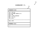
- FIG. 7 is a schematic diagram showing an example of the evaluation information management table in this embodiment.
- FIG. 8 is a flow chart showing an example of the operation of the dynamic two-dimensional code evaluation system in this embodiment.
- FIG. 9 is a schematic diagram showing an example of the overall configuration of the dynamic two-dimensional code evaluation system in this embodiment.
- JIS standard Japanese Industrial Standard JISX05102004 “two-dimensional code symbol-QR code (registered trademark)-” (hereinafter, may be simply referred to as “JIS standard”) or ISO.
- an encoder that can handle non-public (hidden) private datacode words (non-public information) is called an extended encoder (not shown), and a decoder is called an extended decoder.
- the dynamic two-dimensional code evaluation system may be configured by the extension encoder and the extension decoder.
- the two-dimensional code is a two-dimensional code that can record public information and non-public information (such a two-dimensional code is called an extended two-dimensional code.
- the public information is information that can be read by a JIS standard decoder (standard decoder).
- the non-public information is information that cannot be read by the standard decoder and can be extracted only by the extended decoder.
- code word is described as having a length of 8 bits, but it may be a length of 16 bits or have another length such as a length of 1 bit depending on the system. Can also
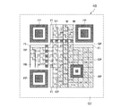
- FIG. 1 is an explanatory diagram of the two-dimensional code 40 (two-dimensional code symbol).
- the two-dimensional code 40 (hereinafter, may be simply referred to as “QR code (registered trademark)”) is available in various sizes from 1 type to 40 type, but here, as an example, the model number “2” is used. Each function will be described by way of example.
- the two-dimensional code 40 has a functional pattern and a coding area.
- the functional pattern is a pattern necessary for searching the symbol position and identifying the characteristic of the two-dimensional code 40 necessary to assist the decoding of the two-dimensional code 40 in the module.
- the coding area is an area in which necessary information is written.
- the functional pattern has a position detection pattern FP, a separation pattern SP, a timing pattern TP, an alignment pattern AP, and a quiet zone QZ.
- the position detection pattern FP is a pattern arranged in at least three corners of the two-dimensional code 40. By identifying the three position detection patterns FP during reading, the direction and position of the code symbol of the two-dimensional code 40 can be correctly recognized.
- the patterning pattern SP is a 1-module-wide bright module arranged around the position detection pattern FP.
- the position detection pattern FP can be distinguished from the code symbol of the two-dimensional code 40.
- the module M is a unit cell that forms a code symbol of the two-dimensional code 40. In principle, 1 bit corresponds to 1 module.
- a group of a plurality of modules M, which are unit cells forming the two-dimensional code 40, is referred to as a module group.
- the timing pattern TP is a pattern in which one dark module and one bright module are linearly arranged alternately. Since the number of modules of the code symbol of the two-dimensional code 40 can be recognized by the timing pattern TP, the model number of the two-dimensional code 40 can be identified by this.
- the alignment pattern AP is a pattern arranged at a position determined by the model number of the two-dimensional code 40. In the case of a large module, the alignment pattern AP functions to assist the search for the position of the two-dimensional code 40.
- the quiet zone QZ is a bright module area with a minimum width of 4 modules that is provided around the authentication information 0.
- the coding area has a data code word, an error correction code word (hereinafter sometimes simply referred to as “correction code word”), and format information FI. Further, in the above description, each function is described by taking the model number “2” as an example. For example, model number information (VI: Version Information) is added to a large model number.
- the format information FI has information of an error correction level and a standard mask pattern (mask pattern defined by JIS standard).
- the standard mask pattern has display patterns of eight types (0 to 7) of masks, and one of the pattern numbers is set. Depending on the set pattern number, variations in black and white dots forming the two-dimensional code 40 are displayed.
- Data code words and error correction code words are data representing information and error correction code words for error correction when data cannot be read, and these are arranged.
- the format information has information about an error correction level applied to the two-dimensional code 40 and a standard mask pattern to be used, and becomes a coding pattern necessary for decoding the coding area.
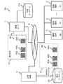
- FIG. 2 is a block diagram showing the overall configuration of the dynamic two-dimensional code evaluation system 50 in the first embodiment.
- the dynamic two-dimensional code evaluation system 50 includes a management server 1.
- the management server 1 includes a management database 1a, and includes a venue device 2 and a plurality of customer terminals 3.
- the dynamic two-dimensional code evaluation system 50 is connected to the hall device 2, a plurality of customer terminals 3 and the like via the public communication network 4 (network).
- the customer terminal 3 images each of the plurality of two-dimensional codes 40 included in the two-dimensional code set 41 dynamically displayed by the venue device 2, evaluates the captured two-dimensional code 40, and confirms various information and services. Get offered.
- the dynamic two-dimensional code evaluation system 50 includes, for example, a plurality of two-dimensional code sets 41 included in the two-dimensional code set 41 generated by the management server 1 in a lottery of a target person or a product or a game at a facility such as an event venue or a live venue.
- the dimension codes 40 are sequentially displayed on the screen, display, etc. provided in the venue device 2.
- the display of a screen or a display is displayed at a speed of 300 milliseconds per frame, for example, as in a moving image, and a plurality of code symbols, such as a moving image, are dynamically displayed as time passes. May be displayed.
- the venue device 2 is connected to the management server 1.
- the management server 1 permits access from the venue device 2, and sets a plurality of two-dimensional codes 40 included in the two-dimensional code set 41 stored in the management database 1a in advance by setting information set by an administrator or the like.
- the evaluation information is transmitted to the customer terminal 3, and the customer terminal 3 captures an image of the two-dimensional code 40 that is sequentially displayed on the screen, the display, or the like provided in the hall device 2.
- the result of the image pick-up at the customer terminal 3 includes a combination of installation information set in advance for the two-dimensional code set 41 and, as described above, a display at a speed of 300 milliseconds per frame, etc. It is possible to display different results depending on the information of the owner of the customer terminal 3 and the state of the customer terminal 3 (for example, imaging specifications, imaging timing, etc.).
- the management server 1, the two-dimensional code set 41 or the two-dimensional code 40 distributed in advance to related parties, staff, customers, etc., is, for example, various information such as held events and live performances, and various related parties.
- the two-dimensional code set 41 is generated on the basis of various information such as roles and characteristics of staff, customers and the like, profiles, functions and specifications of the customer terminal 2 owned.
- the management server 1 transmits the generated two-dimensional code set 41 or the two-dimensional code 40 to the hall device 2.
- the management server 1 refers to the destination information of the related persons, staff, customers, etc. stored in the management database 1a and transmits the generated two-dimensional code set 41 or two-dimensional code 40.
- the two-dimensional code set 41 or the two-dimensional code 40 generated by the management server 1 is electronically generated and, for example, one piece of the two-dimensional code 40 is fixedly displayed on a printed matter or a package as an evaluation target. It may be generated (printed or printed) in a state.
- the two-dimensional code set 41 or the two-dimensional code 40 generated by the management server 1 is used as URL information for displaying on the customer terminal 3 at each distribution destination (for example, related persons, staff, customers, etc.), It is written and sent by sending means such as electronic mail or mail.
- the venue device 2 stores the two-dimensional code set 41 received from the management server 1 in the display database 2a of the venue device 2, and displays a plurality of two-dimensional code 40 based on the setting information from the stored two-dimensional code set 41. You may do so.
- the venue device 2 includes a screen or a display (not shown) that displays the two-dimensional code 40 (two-dimensional code 40a, two-dimensional code 40b, two-dimensional code 40n, etc.) included in the two-dimensional code set 41.
- an imaging device such as a camera that discriminates the two-dimensional code set 41 or the two-dimensional code 40 that is distributed in advance to parties, staff, customers, etc. who come in and out of the hall (Fig. (Not shown) may be provided at the entrance and exit doors and gates. Therefore, the hall apparatus 2 can capture an image of the two-dimensional code set 41 or the two-dimensional code 40 distributed in advance to the related persons, staff, customers, etc. by the image capturing apparatus provided at the door or the gate. As a result, it is possible to prevent falsification and forgery of various tickets and the like.
- the customer terminal 3 holds a plurality of two-dimensional codes 40 which are held by the customer (photographer or imager) and are sequentially displayed on the screen or display of the event venue or live venue, for example. An image is taken by the imaging function or application provided in the terminal 3.
- the two-dimensional code 40 captured by the customer terminal 3 may be sequentially stored in a storage unit of the customer terminal 3 described later, or may be stored in a storage unit (not shown) allocated on the cloud. Good.
- the customer terminal 3 stores one two-dimensional code 40 imaged (selected) by the customer terminal 3 from the two-dimensional code set 41 dynamically displayed, for example, at a specific or arbitrary timing. May be.
- the customer terminal 3 can efficiently store the memory of the customer terminal 3 by storing the two-dimensional code 40 at a specific or arbitrary timing.
- the customer terminal 3 receives the two-dimensional code set 41 from the management server 1, displays the received two-dimensional code set 41, and displays it on the entrance and exit doors and gates of the venue device 2.
- the image may be captured by a provided imaging device or a terminal used by a person involved in the event or live performance, staff, or the like.
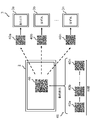
- the two-dimensional code 40 included in the two-dimensional code set 41 displayed on the venue device 2 is, for example, as shown in FIG. 3, as a plurality of two-dimensional codes 40a to 40n over time, as shown in FIG.
- the image is captured by the customer terminal 3.
- the dynamic display is, for example, displayed as if the plurality of two-dimensional codes 40a to 40n two-dimensional code 40 are rotating.
- Each of the customer terminals 3a to 3n images the two-dimensional code 40 dynamically displayed on the hall apparatus 2.
- the dynamically displayed two-dimensional code 40 is a set of two-dimensional codes 40a to 40n that are dynamically displayed on the venue device 2.
- Each of the two-dimensional codes 40a to 40n imaged by each of the customer terminals 3a to 3n is evaluated by each of the customer terminals 3a to 3n, and the respective configuration information of the two-dimensional codes 40a to 40n at the time of imaging
- the corresponding display (“win!”, “out”) is displayed on the customer terminals 3a to 3n.
- FIG. 4 is a schematic diagram showing an example of the configuration of the customer terminal 3 (customer terminal 3a, customer terminal 3b, customer terminal 3c).
- the customer terminal 3 in addition to a personal computer (PC), an electronic device such as a smartphone or a tablet terminal is used.
- the customer terminal 3 includes a housing 10, a CPU (Central Processing Unit) 100, a ROM (Read Only Memory) 101, a RAM (Random Access Memory) 102, a storage unit 103, and I/Fs 104 to 106. ..
- the components 100 to 106 are connected by an internal bus 107.
- the CPU 100 controls the entire customer terminal 3.
- the ROM 101 stores the operation code of the CPU 100.
- the RAM 102 is a work area used when the CPU 100 operates.
- the storage unit 103 stores various kinds of information such as setting information and evaluation information.
- As the storage unit 103 for example, an HDD (Hard Disk Drive), an SSD (solid state drive), or the like is used.
- the customer terminal 3 may have a GPU (Graphics Processing Unit) not shown. By having the GPU, it becomes possible to perform higher-speed arithmetic processing than usual.
- the I/F 104 is an interface for transmitting and receiving various types of information to and from the management server 1, the hall device 2, and the like via the public communication network 4.
- the I/F 105 is an interface for transmitting/receiving information to/from the input unit 109.
- a keyboard, a touch panel, or the like is used as the input unit 109, and a customer, an administrator, or the like who uses the dynamic two-dimensional code evaluation system 50 can input various information or control commands of the customer terminal 3 through the input unit 109. Enter or select.
- the I/F 106 is an interface for transmitting/receiving various information to/from the output unit 108.
- the output unit 108 outputs various information stored in the storage unit 103, the processing status of the customer terminal 3, and the like.
- a display is used as the output portion 108, and may be, for example, a touch panel type. In this case, the output part 108 may include the input part 109.
- FIG. 5 is a schematic diagram showing an example of the functions of the customer terminal 3.
- the customer terminal 3 includes, for example, a reception unit 20, an image pickup unit 21, an analysis unit 22, an evaluation unit 23, a control unit 24, an output unit 25, and a storage unit 26.
- Each function shown in FIG. 5 is realized by the CPU 100 executing a program stored in the storage unit 103 or the like using the RAM 102 as a work area. Further, each function may be controlled by artificial intelligence, for example.
- the "artificial intelligence" may be based on any known artificial intelligence technology.
- the receiving unit 20 analyzes the setting information for analyzing the plurality of two-dimensional codes 40 that are dynamically displayed on the venue device 2 and that constitutes the two-dimensional code set 41, and the customer terminal 3 or an external server (not shown). Receive evaluation information for evaluating the results of the evaluation. When outputting (displaying) the two-dimensional code set 41, the receiving unit 20 also receives the two-dimensional code set 41 generated based on the setting information. The two-dimensional code set 41 received by the receiving unit 20 is dynamically displayed based on the setting information.
- the setting information received by the receiving unit 20 is, for example, various setting information stored in advance in the management database 1a of the management server 1 and associated with the setting information ID registered in the setting information management table 1b.
- the evaluation information is, for example, various kinds of evaluation information associated with the evaluation information ID registered in the evaluation information management table 1c stored in advance in the evaluation information management table 1c.
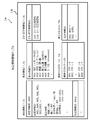
- FIG. 6 shows various types of information stored in the setting information management table 1b.
- the setting management information table 1b setting information for identifying or authenticating the two-dimensional code 40 to be imaged is stored in association with the two-dimensional code 40.
- the setting information ID is stored for each set of two-dimensional codes 40.
- the setting information ID is set as common setting information in the set of two-dimensional codes 40. Therefore, for example, if there are a plurality of two-dimensional codes 40 that are dynamically displayed, they are commonly set for all the two-dimensional codes 40 related to the dynamic display.
- the setting information table is generated by the management server 1, and the setting information table generated via the management server 1 is transmitted to the customer terminal 3.
- the setting information table transmitted to the customer terminal 3 is information to be locally analyzed by the customer terminal 3, and may be analyzed by the management server 1, for example.
- the setting information management table 1b received by the receiving unit 20 of the customer terminal 3 stores various information for analyzing and evaluating the two-dimensional code 40, for example. Items set in the setting information management table 1b are set by, for example, the administrator of the management server 1. Each item to be set is associated with, for example, a display information table, a standard mask pattern table, an error correction word information table, a configuration structure information table, and a display information table.
- Various setting information IDs set in the setting information management table 1b are determined by, for example, the manager or the organizer of the above-mentioned event or live, the holding scale of the event or live, the number of participants, the venue, In addition to the holding time, etc., it is appropriately set according to the conditions of the lottery, etc. Settings are based on various information such as past events and live events, number of participants, held questionnaire information, lottery results, and other past events such as history of events.
- the two-dimensional code 40 is set.
- the setting information ID is given to the plurality of two-dimensional codes 40 forming the two-dimensional code set 41 to be evaluated, and is set as, for example, “0001” or “0002”.
- the setting identified by each setting information ID is, for example, as setting information of the display information table, “A02 (direction)”, “A04 (display position)”, “A05 (display order)”, “A07 (image “Reversal of light and dark)”, “A07 (bright and dark colors forming the code)", and "A08 two-dimensional code type" are set.
- “B01 (Pattern 0)” is set as standard mask pattern table setting information
- “D01 (Public structure open/closed)”, “D02 (Structural connection)”, and “D03 read protection” are set as the structure information table.
- “D04 authentication structure” and display text information “E01 (around!)” and “E02 (out)” are set.
- the set information is information for setting the operation related to the dynamic display, and includes, for example, the number of the two-dimensional codes 40 constituting the two-dimensional code set 41 to be dynamically displayed, the presence/absence of the two-dimensional code 40 serving as the starting point of the evaluation.
- various items such as the number of base points, display time per dynamic display (or total time), coordinates of display position on the customer terminal 3 display or screen (X axis, Y axis), etc. Information is set.
- the base point may be dynamically set for each customer terminal 3.
- the various kinds of information set in the setting information table may be, for example, any one of the setting items, or all the setting items may be set as a combination.
- the setting of the combination may be appropriately selected and set, for example, by the organizer of the event, live performance, or the like, based on information such as the content and scale of the event, the characteristics of the target person, and customer benefits.
- the display information table includes, for example, "A01 (tilt: 1 degree to 360 degrees), “A02: direction (up/down/left/right)”, “A03: front and back sides which are mirror image inversions of code symbols. )”, “A04: display position (X axis, Y axis)”, “A05: display order (nth)”, “A06 (inversion of light and dark of image)”, “A07: light and dark colors forming code ( #Nnnnn)” and “A08 two-dimensional code type” are set. Which item is set with which value is arbitrary.
- the standard mask pattern table for example, eight types “B01 (pattern 0)” to “B08 (pattern 7)” are set as information indicating the standard mask pattern.
- the standard mask pattern is automatically determined based on the standard of the QR code (registered trademark), but which standard mask pattern is set is arbitrary and is combined with other setting information. It is possible to set it.
- the combination of the standard mask patterns is combined with, for example, the display direction (up/down/left/right) of the two-dimensional code 40, up to 32 different settings can be set. Therefore, any one of them or a combination of a plurality of them is an evaluation target of the two-dimensional code 40 that constitutes the two-dimensional code set 41 (for example, “A02: direction (upper)”, “B01 (pattern 2)”. Etc.).
- the error correction word information table can include specific information in the error correction word area before and after processing the error correction word, for example.
- This information is an area that is normally deleted after the processing of the error correction word, but by including the information in this area as an evaluation target, the two-dimensional code set 41 that is dynamically displayed is configured.
- the two-dimensional code 40 to be evaluated can be evaluated from the plurality of two-dimensional codes 40 to be evaluated.
- "C01 (before error correction processing)" and "C02 (after error correction processing)" are set as information indicating before and after processing of error correction words. Which is set as the area is arbitrary.
- the configuration structure information table can include, for example, at least one of the configuration structure of public/non-disclosure regarding the configuration structure of a specific code word of the two-dimensional code, structural connection, read protection, and authentication structure. is there.
- the disclosure/non-disclosure regarding the configuration structure of a specific code word of the two-dimensional code is, for example, in the case where the two-dimensional code 40 is not disclosed, the confidential data code of the two-dimensional code 40 is replaced with a part or all of the embedded code and the end identification. Include placement information after code. As a result, the secret data code placed after the terminal identification code is not read by the reading device of general specifications.
- the structural connection is provided by, for example, the above-mentioned JIS standard, indicates the connection state of the plurality of two-dimensional codes 40, and includes this information as the structural connection.
- the read protection is performed by, for example, performing a masking process using a standard mask pattern on the two-dimensional code 40 and performing a protection coding process on a code block by a protection coding pattern defined separately from the masking process.
- the standard reading means that does not know this convention or the protection encoding pattern cannot read the code because the configuration as a two-dimensional code cannot be established. Is included in the read information.
- the authentication structure includes, for example, related code information for identifying that a plurality of related two-dimensional codes 40 are related to each other in the confidential data code of the two-dimensional code 40. Includes information about the structure.
- FIG. 7 shows various information stored in the evaluation information management table 1c.
- the evaluation management information table 1c stores evaluation information for identifying or authenticating the captured two-dimensional code 40 from the two-dimensional code 40 forming the two-dimensional code set 41 that is dynamically displayed.
- the evaluation information management table 1c stores the evaluation information ID of the two-dimensional code 40 to be evaluated for each two-dimensional code set 41.
- One or a plurality of evaluation information IDs are set as evaluation information common to a plurality of two-dimensional codes 40 forming the two-dimensional code set 41. Therefore, for example, if there are a plurality of two-dimensional codes 40 that form the two-dimensional code set 41 that is dynamically displayed, all the two-dimensional codes 40 that are dynamically displayed are evaluated in common. What kind of evaluation is performed is arbitrary, and as described above, for example, it is possible to combine information regarding holding of events and live performances, information regarding venue equipment, information regarding the customer terminal 3 (customer), and the like.
- the various evaluation information IDs set in the evaluation information management table 1c are determined by, for example, the manager or the organizer of the above-mentioned event or live, and the holding scale of the event or live, the number of participants, the venue, In addition to the holding time, etc., it is appropriately set according to the conditions of the lottery, etc. Settings are based on various information such as past events and live events, number of participants, held questionnaire information, lottery results, and other past events such as history of events.
- the two-dimensional code 40 is set. The kind of display is arbitrary.
- the evaluation information ID is given to a set of a plurality of two-dimensional codes 40 to be evaluated, and is set as, for example, “0001” or “0002”.
- the setting identified by each evaluation information ID is, for example, “right” for “A02 (direction)”, “A04 (display) for each item set in the display information table described above as evaluation information.
- Position) "coordinates XXX, YYY”, “A05 (display order)" to "3”, "A07 (bright and dark colors forming the code)” to "#000000”, "A08” “Pattern 0” is set as evaluation information for “(two-dimensional code type)” and “B01 (standard mask pattern)”.
- the kind of display is arbitrary.
- the customer terminal 3 stores a display text as information to be displayed on the customer terminal 3 according to the evaluation result.
- "E01 (around!)” is stored as a display when it is evaluated that the evaluation conditions are matched
- "E02 (outlier)” is stored as a display when the evaluation conditions are not matched.
- the display text stored here may be, for example, still images such as illustrations and photographs, moving images, and audio data, in addition to the text information. What kind of content is displayed is arbitrary.
- the image capturing unit 21 captures the dynamically displayed two-dimensional code 40 displayed by the hall device 2.
- the image capturing unit 21 activates an image capturing function (camera function) provided in the customer terminal 3 or an image capturing application to capture an image.
- the imaging may be a still image or a moving image.
- the imaging unit 21 images the two-dimensional code set 41 or the two-dimensional code 40 and stores the image in the storage unit 103 of the customer terminal 3 or the storage unit 26 of the customer terminal 3 described later.
- the image capturing unit 21 When capturing the two-dimensional code set 41 or the two-dimensional code 40, the image capturing unit 21 also acquires various pieces of information related to the image capturing conditions such as the image capturing date and time and the image capturing location, and captures the image. It may be stored in the storage unit 103, the storage unit 26, or the like in association with each of the dimension codes 40.
- the analysis unit 22 analyzes the captured two-dimensional code set 41 or the two-dimensional code 40 based on the setting information.
- the analysis by the analysis unit 22 is performed by the management server 1 in addition to the customer terminal 3, for example, in the case where the customer terminal 3 cannot perform processing due to security reasons, the management server 1 receives the analysis result. It may be performed (not shown).
- the analysis unit 22 analyzes based on various setting information regarding the two-dimensional code set 41 or the two-dimensional code 40 received by the receiving unit 20.
- the management server 1, the hall apparatus 2, and the customer terminal 3 have previously decided on which setting information ID the analysis unit 22 will analyze the captured two-dimensional code set 41 or the two-dimensional code 40. May be.
- the customer selects the setting information ID set for the two-dimensional code set 41 or the two-dimensional code 40 to be imaged from the plurality of setting information IDs displayed via the customer terminal 3.
- the analysis unit 22 analyzes each setting of the two-dimensional code 40 based on the setting identified by the selected setting information ID.
- the analysis unit 22 based on the structure forming the imaged two-dimensional code set 41 or the two-dimensional code 40, the dynamically displayed state, or the change or order of the dynamically displayed two-dimensional code set 41,
- the setting information received by the receiving unit 20 is analyzed based on the setting items included therein.
- the analysis unit 22 compares, for example, the captured two-dimensional code set 41 or the two-dimensional code 40 and each setting information and setting information received in advance with the setting information included in the setting item.
- the setting items are, for example, "A01 (inclination: 1 degree to 360 degrees), "A02: direction (up/down/left/right)", “A03: front and back (a front/back) that is a mirror image inversion of the code symbol”.
- A04 display position (X axis, Y axis)
- A05 display order (nth number)
- A07 light and dark colors composing code (#nnnnnn)
- B01 pattern 0
- each setting item that constitutes the imaged two-dimensional code 40 and preset is compared with each setting information recorded in the setting information management table 1b.
- the analysis unit 22 compares, based on the setting information of the two-dimensional code set 41, whether it is the two-dimensional code set 41 or the two-dimensional code 40 that match in a specific setting item, and the two-dimensional code set imaged from those results. 41 or the two-dimensional code 40 is analyzed. For these setting items, a plurality of setting information can be set and analyzed.
- the analysis unit 22 is correct if there is no difference between the setting items that make up the captured two-dimensional code set 41 or the two-dimensional code 40, the setting information, and the setting items preset as the set information, based on the result of the analysis.
- the two-dimensional code set 41 or the two-dimensional code 40 to be evaluated is used. As a result, the two-dimensional code set 41 or the two-dimensional code 40 that may be falsified or forged can be distinguished, and the two-dimensional code set 41 or the two-dimensional code 40 to be evaluated can be excluded.
- the analysis unit 22 evaluates the two-dimensional code set 41. Alternatively, it is determined that the two-dimensional code 40 is not used, and the analysis process is ended, and the two-dimensional code set 41 or the two-dimensional code 40 that is dynamically displayed next is imaged.
- the analysis unit 22 uses the two-dimensional code set 41 or the two-dimensional code 40 stored in the storage unit 103 of the customer terminal 3 in addition to the two-dimensional code set 41 or the two-dimensional code 40 captured by the image capturing unit 21.
- the two-dimensional code set 41 or the two-dimensional code 40 read out may be analyzed.
- the two-dimensional code set 41 or the two-dimensional code 40 may be analyzed not only by the customer terminal 3 but also by an external server or the like (not shown).
- ⁇ Evaluation unit 23 When the evaluation unit 23 determines that the two-dimensional code set 41 or the two-dimensional code 40 to be evaluated is determined according to the result of the analysis by the analysis unit 22, the evaluation unit 23 further determines the evaluation information previously received by the reception unit 20. Based on the evaluation. Specifically, the evaluation unit 23 evaluates the condition of each setting information of the setting information analyzed by the analysis unit 22 based on each target information stored in the evaluation information management table 1c.
- the evaluation unit 23 refers to the evaluation information stored in the evaluation information management table 1c and, for example, “right” for “A02 (direction)” and “coordinates XXX, YYY” for “A04 (display position)”. , “A05 (display order)” to “3”, “A07 (light and dark colors that make up the code)” to "#000000”, and “B01 (standard mask pattern)” to "pattern” It is evaluated whether the evaluation information is set as “0” or the like, and if some or all of these evaluation conditions are matched, “E01 (around!)” is displayed on the output unit 25 of the customer terminal 3. To do. What is displayed is arbitrary, and other words or the like may be used.
- the evaluation unit 23 displays “E02 (out)” on the output unit 25 of the customer terminal 3, and the two-dimensional code 40 that is dynamically displayed next. Is imaged.
- the evaluation unit 23 reads the two-dimensional code set 41 or the two-dimensional code 40 analyzed by the analysis unit 22 into the storage unit 103 of the customer terminal 3, evaluates the read two-dimensional code set 41 or the two-dimensional code 40, The evaluation result is displayed on the output unit 25 of the customer terminal 3.
- imaging may be performed a plurality of times.
- the two-dimensional code set 41 can be dynamically displayed like a moving image.
- the analysis unit 22 appropriately performs analysis according to the image capturing by the image capturing unit 21, and the evaluation unit.
- the imaged two-dimensional code set 41 or a plurality of two-dimensional codes 40 may be evaluated by the evaluation by 23.
- Control unit 24 controls the reception unit 20, the imaging unit 21, the analysis unit 22, the evaluation unit 23, the output unit 25, and the storage unit 26 of the customer terminal 3.
- the output unit 25 outputs the analysis result by the analysis unit 22 and the evaluation result by the evaluation unit 23.
- the output unit 25 transmits the analysis result and the evaluation result to the output unit 108 via the I/F 106, and, for example, the analysis result or the evaluation result to the management server 1, the hall device 2, etc. via the I/F 104. May be sent.
- the output unit 25 may output various conditions such as setting information, for example.
- the storage unit 26 stores the setting information received by the receiving unit 20 and various pieces of evaluation information in the storage unit 103.
- the storage unit 26 retrieves various types of information such as the information tables stored in the storage unit 103 as necessary.
- the information table stores various kinds of information such as previously acquired past setting information and evaluation information.
- the management server 1 stores a database relating to various types of information as a management database 1a.
- a management database 1a for example, various information sent via the public communication network 4 is accumulated.
- a setting information management table 1b and an evaluation information management table 1c which will be described later, are stored, and information similar to that of the storage unit 103 is stored.
- Various information may be transmitted and received.
- the management server 1 may perform analysis processing based on, for example, a defect in the customer terminal 3, processing capacity or security of the customer terminal 3, or the amount of information of the two-dimensional code set 41 or the two-dimensional code 40 to be processed. A part or the whole may be processed by the analysis unit 22 (not shown).
- the venue device 2 has the same configuration as the customer terminal 3 described above (not shown), and an electronic device such as a personal computer (PC) is used.
- the output part 108 of the venue device 2 is equipped with, for example, a large-sized display or projector, and displays or projects the two-dimensional code set 41 or the two-dimensional code 40 at the event venue, the live venue, or the like as described above. There may be a plurality of large-sized displays and screens at event venues, live venues, etc.
- the two-dimensional code set 41 or the two-dimensional code 40 has the same two-dimensional code 40 sequentially displayed on each display or screen. It is controlled by the control unit 24 of the venue device 2 so as to be projected.
- the display and screen are targeted for the venue device 2, but may be, for example, a television screen or a game screen at home.
- the venue device 2 stores a database relating to various information regarding the two-dimensional code set 41 or the two-dimensional code 40 to be dynamically displayed as a display database 2a.
- the display database 2a stores, for example, various kinds of information transmitted via the public communication network 4.
- setting information regarding the display or projection of the two-dimensional code set 41 or the two-dimensional code 40 in the hall apparatus 2 is stored.
- the venue device 2 displays or projects the two-dimensional code set 41 or the two-dimensional code 40 based on the setting information stored in the display database 2a.
- Various kinds of information may be stored in the display database 2a, and various kinds of information may be transmitted/received to/from the management server 1 and the customer terminal 3 via the public communication network 4. Further, the management server 1 transmits and delivers as a moving image. May be done.
- the public communication network 4 is an internet network or the like to which the management server 1, the venue device 2, the customer terminal 3 and the like are connected via a communication circuit.
- the public communication network 4 may be configured by a so-called optical fiber communication network.
- the public communication network 4 is not limited to a wired communication network, but may be realized by a wireless communication network, and may also be a general ground wave, a radio wave for TV broadcasting such as satellite broadcasting.
- FIG. 8 is a flowchart showing an example of the operation of the dynamic two-dimensional code evaluation system 50 in this embodiment.
- the receiving unit 20 evaluates, for example, setting information for analyzing the two-dimensional code set 41 or the two-dimensional code 40 dynamically displayed on the venue apparatus 2 from the management server 1 and the analyzed result.
- the evaluation information for receiving is received (reception means S110).
- the receiving unit 20 stores, for example, various information in the setting information management table 1b stored in the management database 1a of the management server 1 or the two-dimensional code set 41 or the two-dimensional code 40 dynamically displayed in the venue device 2.
- the setting information associated with the related setting information ID, the set information, and the evaluation information of the evaluation information management table 1c are received, and each received information is stored in the storage unit 103.
- Imaging unit 21 images, for example, the two-dimensional code set 41 or the two-dimensional code 40 that is dynamically displayed on the venue device 2 (imaging unit S120).
- the imaging unit 21 sequentially images the dynamically displayed two-dimensional code set 41 or the two-dimensional code 40 and also dynamically displays a series of the two-dimensional code set 41 or the two-dimensional code 40 (the two-dimensional code 40a to The two-dimensional code 40n) is recorded as a moving image.
- the image capturing unit 21 may also acquire information such as the date and time when the image was captured, the location, and the person who captured the image, and store the information in the storage unit 103 or the like via the storage unit 26.
- the analysis unit 22 analyzes the imaged two-dimensional code set 41 or the two-dimensional code based on the setting information (analyzing means S130).
- the analysis unit 22 reads the setting information received in advance by the reception unit 20 and stored in the storage unit 103, and analyzes each piece of information forming the imaged two-dimensional code set 41 or two-dimensional code 40.
- the analysis of the two-dimensional code 40 in the analysis unit 22 may be performed not only by the customer terminal 3 but also by the management server 1, for example. In that case, the customer terminal 3 transmits the captured two-dimensional code 40 to the management server 1.
- the analysis unit 22 compares each setting item forming the captured two-dimensional code set 41 or the two-dimensional code 40 with the setting information received in advance. In addition, the analysis unit 22 compares, based on the set information, whether it is the specific two-dimensional code set 41 or the two-dimensional code 40, and if there is no difference in the preset setting items based on the analysis results, a correct evaluation is performed. The target two-dimensional code set 41 or the two-dimensional code 40 is used.
- the evaluation unit 23 evaluates the result of the analysis by the analysis unit 22 based on the evaluation information (evaluation means S140).
- the evaluation unit 23 reads the evaluation information previously received by the reception unit 20 and stored in the storage unit 103, is analyzed by the analysis unit 22, and is analyzed as the correct two-dimensional code set 41 or two-dimensional code 40 and the two-dimensional code set.
- the setting condition of each setting item of 41 or the two-dimensional code 40 is evaluated. If all of the setting conditions and the evaluation conditions are the same, the evaluation unit 23 displays, for example, "win! on the output unit 25 of the customer terminal 3. !! ”Is output, and if they do not match, “out” is output.
- FIG. 9 is a schematic diagram showing an example of the dynamic two-dimensional code evaluation system 50 according to the second embodiment.
- the customer terminal 3 (customer terminal 3a, customer terminal 3b to customer terminal 3n, etc.) has a two-dimensional code set 41 or a two-dimensional code 40 (two-dimensional code 40a, two-dimensional code 40a, The dimension code 40b, the two-dimensional code 40n, etc. are output (displayed), and the two-dimensional code set 41 or the two-dimensional code 40 (two-dimensional code 40) that is displayed for each customer terminal 3 on the imaging unit 21 (for example) provided in the venue apparatus 2 is displayed. This is the point where the dimension code 40a, the two-dimensional code 40b, and the two-dimensional code 40n) are imaged. The description of the same configurations as those described above will be omitted.
- the customer terminal 3 receives the two-dimensional code set 41 or the two-dimensional code 40 which the customer terminal 3 previously received from the management server 1 or the like and stored in the storage unit 26 of the customer terminal 3, and the read two-dimensional code set 41.
- the two-dimensional code 40 is displayed on the display or the like of the customer terminal 3 via the output unit 25 of the customer terminal 3.
- Each of the customer terminals 3 includes an output unit 25 that outputs a set of a plurality of two-dimensional codes, and the receiving unit 20 receives the setting information and the two-dimensional code set 41 generated by the setting information. After that, the output unit 25 dynamically displays the two-dimensional code set 41 based on the received setting information.
- an imaging unit 21 is provided at the entrance and exit doors and gates of the venue.
- the image capturing unit 21 is the same as the image capturing unit 21 of the customer terminal 3 described above, and captures an image of the two-dimensional code set 41 or the two-dimensional code 40, and based on the setting information and the evaluation information received from the management server 1.
- the analysis unit 22 analyzes the two-dimensional code set 41 or the two-dimensional code 40 of the customer terminal 3, and the evaluation unit 23 evaluates the analysis result based on the evaluation information to the imaged two-dimensional code set 41 or the two-dimensional code 40. Then, for example, authentication of a legitimate customer is performed.
- the setting information and the evaluation information received by the receiving unit 20 are, for example, according to the customer information such as the profile and characteristics of each customer, the content of the event or live event, the size of the venue, the facility, etc. It may be information generated in advance. Therefore, it is possible to capture an image of the two-dimensional code set 41 or the two-dimensional code 40 that is dynamically displayed according to the customer and the date and time (content) of the event. As a result, the customer can analyze and evaluate the two-dimensional code set 41 or the two-dimensional code 40 captured in real time at the venue, and can prevent the output by the falsified or forged two-dimensional code set 41 or the two-dimensional code 40. ..
- the setting information constitutes the inclination, the direction, the front and back that is the mirror image inversion of the code symbol, the display position, the display order, and the code regarding the display of the two-dimensional code set 41 or the two-dimensional code 40.
- the evaluation information is at least one of light and dark colors, and the evaluation information includes a tilt, a direction, a front and back that is a mirror image inversion of a code symbol, a display position, a display order, and a code regarding a display previously specified as an evaluation target. At least one of the light and dark colors, and the information is received. Therefore, the analysis and evaluation of the two-dimensional code set 41 or the two-dimensional code 40 imaged by the customer terminal 3 can be complicated.
- the two-dimensional code set 41 or the two-dimensional code 40 can be prevented. Further, since the operation and the display according to the analysis and evaluation can be finely set, the optimum display (message or the like) or privilege (coupon) can be given to each customer in advance.
- the two-dimensional code set 41 or the plurality of two-dimensional codes 40 is dynamically displayed so as to rotate clockwise around the center of the two-dimensional code 40, or is displayed vertically and horizontally.
- various evaluations and outputs can be associated with each other, which may lead to an increase in imaging opportunities when a customer participates in an event and an improvement in motivation.
- the receiving unit 20 changes the setting information and the evaluation information (tilt, direction regarding display of the two-dimensional code 40, front and back which is mirror image inversion of code symbol, display position, display order, and A combination of at least one of the light and dark colors forming the code is received in real time. Therefore, the received setting information and evaluation information can be reflected. As a result, it becomes possible to analyze and evaluate the two-dimensional code set 41 or the two-dimensional code 40 which is dynamically displayed in front of the eyes while being at the event or live venue, and is linked to the holding or progress of the event or live. You can check the output.
- the setting information is an identifier number related to a standard mask pattern of the two-dimensional code 40
- the evaluation information is an identifier number of a standard mask pattern that is specified in advance as an evaluation target. To receive. Therefore, it is further combined with at least one of the information regarding the inclination, the direction, the front and back that is a mirror image inversion of the code symbol, the display position, the display order, and the light and dark colors forming the code, regarding the display of the two-dimensional code 40. Is possible. As a result, the analysis and evaluation of the two-dimensional code set 41 or the two-dimensional code 40 captured by the customer terminal 3 can be complicated, and the tampering and forgery of the dynamically displayed two-dimensional code 40 can be prevented.
- the setting information can be an error correction word included in the two-dimensional code 40
- the evaluation information can be an error correction word specified in advance as an evaluation target. Therefore, the analysis and evaluation of the two-dimensional code 40 captured by the customer terminal 3 can be complicated. As a result, it is possible to prevent the dynamic alteration and forgery of the two-dimensional code 40.
- each means S110 to S140 is stored in a computer as each step (for example, reception step, imaging step, analysis step, evaluation step). It may be executed.
- the two-dimensional code 40 dynamically displayed as described above can be analyzed based on the setting information, and the analysis result can be evaluated based on the evaluation information.
- the organizer of an event or live performance can mass-produce the two-dimensional code 40 to be dynamically displayed, can be widely distributed as electronic data, and can be practically used.
- the dynamic two-dimensional code evaluation method is setting information for analyzing a set of a plurality of two-dimensional codes that are dynamically displayed, and evaluation information for evaluating the analyzed result.
- the means and the analysis result can be provided by the evaluation means that performs the evaluation means S140 that evaluates based on the evaluation information.
- the evaluation unit 23 may further associate other information with the customer terminal 3 (target person) set in the evaluation information table based on the evaluation result. This makes it possible to provide a different added value even between the customer terminals 3 that match the evaluation conditions.
- the analysis and evaluation are performed based on the setting information and the evaluation information, so that the code types of different standards can be mixed, for example.
- the two-dimensional code set 41 is dynamically displayed while the plurality of two-dimensional codes 40 are circulated, and the two-dimensional code set 41 is moved once (one loop) as in streaming distribution. It may be a target display. Furthermore, the start time of the dynamic display may be set and the dynamic display may be performed at the set time. These dynamic displays correspond to the content (for example, advertisements and advertisements) and other moving images (for example, promotional videos, notice videos, etc.) that are arranged and arranged by the organizer of the event or live. It may be attached and set.
- the venue device 2 may be, for example, a store terminal installed in a store or the like (not shown).
- the store terminal dynamically displays the predetermined two-dimensional code set 41 or the two-dimensional code 40, and the customer who visits the store takes an image with the imaging unit 21 of the customer terminal 3.
- the customer terminal 3 performs the above-described analysis and evaluation based on the captured two-dimensional code set 41 or the two-dimensional code 41, for example, based on the setting information and the evaluation information transmitted in advance by the store server.
- the evaluation result may be displayed.
- the evaluation result displayed on the customer terminal 3 may be, for example, coupon information valid in the store.
- the customer terminal 3 of the customer who has visited the store has a predetermined two-dimensional code set. 41 or the two-dimensional code 40 is dynamically displayed.
- the store terminal captures an image of the two-dimensional code set 41 or the two-dimensional code 40 that is dynamically displayed on the customer terminal 3, and performs the aforementioned analysis and evaluation based on the setting information and the evaluation information stored in advance, The evaluation result may be displayed.
- the evaluation result displayed on the shop terminal becomes, for example, customer authentication information, and it is possible to confirm whether or not the customer is a legitimate registered customer.
- the management server 1 transmits the two-dimensional code set 41 or the two-dimensional code 40 to the customer terminal 3a, and the customer terminal 3a displays the received two-dimensional code set 41 or the two-dimensional code 40.
- the two-dimensional code set 41 or the two-dimensional code 40 dynamically displayed on the customer terminal 3a is imaged and analyzed and evaluated based on the setting information and the evaluation information to evaluate.
- the results are displayed on the customer terminals 3b to 3n. Since the points can be exchanged and the gifts can be transmitted through the two-dimensional code set 41 and the two-dimensional code 40 that are dynamically displayed through the respective customer terminals 3, it is possible to confirm the person who is the requester or the requestee and various It is possible to prevent falsification and forgery of tickets, etc.
- the two-dimensional code set 41 generated by the management server 1 may be used as a one-time password generation device that displays valid numbers in synchronization with the management server or the like. Good (not shown).
- a valid number is generated on the display unit of the one-time password generation device so that it changes over time, and this is used as a password for authentication. If the generator and the authenticator do not share the same secret, the so-called "answer synchronization" cannot be achieved.
- the generated valid number is displayed.For example, by recording the displayed valid number and using the recorded number as another input value, spoofing login etc. is possible. Become.
- the display pattern of the two-dimensional code set 41 or the two-dimensional code 40 that is dynamically displayed cannot record a display pattern and is dynamically changed. Of these, I cannot understand which two-dimensional code 40 is correct.
- the dynamically displayed two-dimensional code set or two-dimensional code 40 can be appropriately imaged on the reading side, and the imaged image may be analyzed and evaluated via the management server 1, for example. With such a configuration, for example, it is possible to disperse the processing and load related to analysis and evaluation, ensure security, and realize efficient processing.
- the customer terminal 3 may be evaluated by a combination of the dynamically displayed two-dimensional code set 41 and another two-dimensional code 40 not shown (for example, printed on a paper medium). ..
- the customer captures an image of the two-dimensional code 40 distributed in advance via the customer terminal 3, and by combining the evaluation result of the captured two-dimensional code 40 and the two-dimensional code set 41 captured thereafter,
- the two-dimensional code 40 to be evaluated may be evaluated from the dynamically displayed two-dimensional code set 41.
- one of the two-dimensional codes 40 may be evaluated from the dynamically displayed two-dimensional code set 41, and the two-dimensional code 40 specified by the evaluated two-dimensional code 40 may be evaluated. .. With such a configuration, it is possible to operate authentication using the two-dimensional code 40 that is not easily tampered with or forged.
- the two-dimensional code 40 is also applied to code symbols of various two-dimensional codes such as DataMatrix (registered trademark) or PDF417 in addition to the QR code (registered trademark). It is possible.
- the two-dimensional code standard is defined by the JIS standard in Japan and the ISO standard internationally, for example.
- the two-dimensional code is, for example, JIS X 0510:2004 two-dimensional code symbol-QR code (registered trademark)-, ISO/IEC 18004:2000, Information Technology-Automatic identification and datacapacitytechniquecodes-Benchmarking-Body code-R-code. Are known.
- JIS X 0512 2015 Information technology-Automatic recognition and data acquisition technology-Barcode symbol system specification-Data matrix, ISO/IEC 16022:2006, Information technology-Automatic identification data-capacity.
- Matrix bar code symbology specification etc. are known.
- PDF417 code for example, JIS X 0508:2010 barcode symbol system specification-PDF417, ISO/IEC 15438:2006, Information technology-identification proficiency and datacapacity technology4 data-capacity technology4.
- management server 1a management database 1b: setting information management table 1c: evaluation information management table 10: case 100: CPU 101: ROM 102: RAM 103: Storage unit 104 to 106: I/F 107: Internal bus 108: Output part 109: Input part 2: Venue device 2a: Display database 20: Reception part 21: Imaging part 22: Analysis part 23: Evaluation part 24: Control part 25: Output part 26: Storage part 3: Customer terminal 3a: Customer terminal 3b: Customer terminal 3c: Customer terminal 3n: Customer terminal 4: Public communication network 40: Two-dimensional code 40a: Two-dimensional code 40b: Two-dimensional code 40n: Two-dimensional code 41: Two-dimensional code set 50: Dynamic two-dimensional code evaluation system S110: Receiving means S120: Imaging means S130: Analyzing means S140: Evaluation means
Abstract
Le problème abordé par la présente invention est de fournir un procédé d'évaluation de code bidimensionnel dynamique, un système d'évaluation de code bidimensionnel dynamique et un programme d'évaluation de code bidimensionnel dynamique qui utilisent une pluralité de codes bidimensionnels qui sont modifiés et affichés dynamiquement en série. La solution de la présente invention comprend : une unité de réception (20) qui reçoit des informations de configuration permettant d'analyser un ensemble d'une pluralité de codes bidimensionnels (40) qui sont affichés dynamiquement, et des informations d'évaluation permettant d'évaluer le résultat analysé ; une unité de capture d'image (21) qui capture une image des codes bidimensionnels (40) qui sont affichés dynamiquement ; une unité d'analyse (22) qui analyse les images capturées des codes bidimensionnels (40) en fonction des informations de configuration ; et une unité d'évaluation (23) permettant d'évaluer le résultat d'analyse provenant de l'unité d'analyse (22) en fonction des informations d'évaluation.
Priority Applications (4)
| Application Number | Priority Date | Filing Date | Title |
|---|---|---|---|
| JP2020533320A JP7090938B2 (ja) | 2019-02-15 | 2020-02-10 | 動的二次元コード評価方法、動的二次元コード評価システム、及び動的二次元コード評価プログラム |
| CN202080012768.4A CN113474784A (zh) | 2019-02-15 | 2020-02-10 | 动态二维码评价方法、动态二维码评价系统和动态二维码评价程序 |
| EP20755927.9A EP3926520A4 (fr) | 2019-02-15 | 2020-02-10 | Procédé d'évaluation de code bidimensionnel dynamique, système d'évaluation de code bidimensionnel dynamique et programme d'évaluation de code bidimensionnel dynamique |
| US17/430,585 US20220129653A1 (en) | 2019-02-15 | 2020-02-10 | Dynamic two-dimensional code evaluation method, dynamic two-dimensional code evaluation system, and dynamic two-dimensional code evaluation program |
Applications Claiming Priority (2)
| Application Number | Priority Date | Filing Date | Title |
|---|---|---|---|
| JP2019026107 | 2019-02-15 | ||
| JP2019-026107 | 2019-02-15 |
Publications (1)
| Publication Number | Publication Date |
|---|---|
| WO2020166549A1 true WO2020166549A1 (fr) | 2020-08-20 |
Family
ID=72044852
Family Applications (1)
| Application Number | Title | Priority Date | Filing Date |
|---|---|---|---|
| PCT/JP2020/005090 WO2020166549A1 (fr) | 2019-02-15 | 2020-02-10 | Procédé d'évaluation de code bidimensionnel dynamique, système d'évaluation de code bidimensionnel dynamique et programme d'évaluation de code bidimensionnel dynamique |
Country Status (5)
| Country | Link |
|---|---|
| US (1) | US20220129653A1 (fr) |
| EP (1) | EP3926520A4 (fr) |
| JP (1) | JP7090938B2 (fr) |
| CN (1) | CN113474784A (fr) |
| WO (1) | WO2020166549A1 (fr) |
Cited By (2)
| Publication number | Priority date | Publication date | Assignee | Title |
|---|---|---|---|---|
| WO2022114180A1 (fr) * | 2020-11-30 | 2022-06-02 | 株式会社Ark | Procédé et système de génération d'un groupe de codes bidimensionnels dynamiques |
| US11586118B2 (en) * | 2020-09-11 | 2023-02-21 | Ghangxin Memory Technologies, Inc. | Alignment mark evaluation method and alignment mark evaluation system |
Citations (5)
| Publication number | Priority date | Publication date | Assignee | Title |
|---|---|---|---|---|
| JP2002260099A (ja) * | 2001-03-05 | 2002-09-13 | Toshiba Tec Corp | 商品販売データ処理装置、携帯型電子端末、商品販売システム、クーポン値引き方法及びプログラム |
| JP2012181645A (ja) | 2011-03-01 | 2012-09-20 | Nippon Hoso Kyokai <Nhk> | 認証サーバ、認証プログラムおよび認証システム |
| JP2014049063A (ja) | 2012-09-04 | 2014-03-17 | Casio Comput Co Ltd | 三次元コード読取方法及び三次元コード読取装置 |
| US20150136846A1 (en) * | 2013-08-07 | 2015-05-21 | International Business Machines Corporation | Creation and management of dynamic quick response (qr) codes |
| JP2016085615A (ja) * | 2014-10-27 | 2016-05-19 | 株式会社デンソー | 情報取得システム、サーバ及び情報提供プログラム |
Family Cites Families (18)
| Publication number | Priority date | Publication date | Assignee | Title |
|---|---|---|---|---|
| JP3516144B1 (ja) * | 2002-06-18 | 2004-04-05 | オムロン株式会社 | 光学情報コードの読取方法および光学情報コード読取装置 |
| JP2007265354A (ja) * | 2006-03-30 | 2007-10-11 | Denso Wave Inc | 二次元コードの表示方法、qrコード、表示媒体、プログラムおよび二次元コード読取装置 |
| US8567681B2 (en) * | 2011-03-22 | 2013-10-29 | Carefusion 303, Inc. | Displaying a barcode on a display of an infusion pump |
| US8792141B2 (en) * | 2011-06-09 | 2014-07-29 | Xerox Corporation | Embedded form extraction definition to enable automatic workflow configuration |
| JP5879831B2 (ja) * | 2011-09-02 | 2016-03-08 | 株式会社ニコン | 電子カメラおよび画像処理プログラム |
| JP5978315B2 (ja) * | 2013-10-30 | 2016-08-24 | 株式会社トッパンTdkレーベル | 二次元コード生成方法、および、二次元コード読み取り方法 |
| CN103745151B (zh) * | 2014-01-08 | 2017-01-25 | 杭州晟元数据安全技术股份有限公司 | 一种二维码与动态密码相结合的身份认证方法 |
| CN103903038A (zh) * | 2014-02-21 | 2014-07-02 | 黄昱钊 | 动态显示二维码的系统及其实现方法、应用 |
| US9189722B2 (en) * | 2014-03-24 | 2015-11-17 | Cellum Innovacios Es Szolgal Tato Zrt | Systems and methods for motion two dimensional codes |
| JP5914579B2 (ja) * | 2014-06-16 | 2016-05-11 | 株式会社トッパンTdkレーベル | 秘匿対象情報の隠蔽方法、秘匿対象情報隠蔽装置、プログラム、秘匿対象情報の抽出方法、および、秘匿対象情報抽出装置 |
| JP2016024576A (ja) * | 2014-07-18 | 2016-02-08 | 日本電信電話株式会社 | 送信装置及び情報伝送方法 |
| JP5827738B1 (ja) * | 2014-10-15 | 2015-12-02 | 株式会社トッパンTdkレーベル | 二次元コード生成方法、二次元コード生成装置、プログラム、二次元コード、二次元コード読み取り方法、および、二次元コード読み取り装置 |
| JP6016280B2 (ja) * | 2014-11-28 | 2016-10-26 | Necプラットフォームズ株式会社 | バーコード評価装置、バーコード画像生成システム、バーコード評価方法、バーコード画像生成方法及びバーコード評価プログラム |
| US10318781B2 (en) * | 2015-03-30 | 2019-06-11 | Temptime Corporation | Two dimensional barcode with dynamic environmental data system, method, and apparatus |
| CN106960427A (zh) * | 2016-01-11 | 2017-07-18 | 中兴通讯股份有限公司 | 二维码图像处理的方法和装置 |
| CN108269174A (zh) * | 2018-01-22 | 2018-07-10 | 成都国盛天丰网络科技有限公司 | 一种基于动态二维码的限时评价方法 |
| US20200065537A1 (en) * | 2018-08-22 | 2020-02-27 | Zebra Technologies Corporation | Automatic form data reading |
| US20230394561A1 (en) * | 2022-06-02 | 2023-12-07 | Snap Inc. | Augmented reality self-scanning and self-checkout |
-
2020
- 2020-02-10 JP JP2020533320A patent/JP7090938B2/ja active Active
- 2020-02-10 US US17/430,585 patent/US20220129653A1/en active Pending
- 2020-02-10 CN CN202080012768.4A patent/CN113474784A/zh active Pending
- 2020-02-10 EP EP20755927.9A patent/EP3926520A4/fr active Pending
- 2020-02-10 WO PCT/JP2020/005090 patent/WO2020166549A1/fr unknown
Patent Citations (5)
| Publication number | Priority date | Publication date | Assignee | Title |
|---|---|---|---|---|
| JP2002260099A (ja) * | 2001-03-05 | 2002-09-13 | Toshiba Tec Corp | 商品販売データ処理装置、携帯型電子端末、商品販売システム、クーポン値引き方法及びプログラム |
| JP2012181645A (ja) | 2011-03-01 | 2012-09-20 | Nippon Hoso Kyokai <Nhk> | 認証サーバ、認証プログラムおよび認証システム |
| JP2014049063A (ja) | 2012-09-04 | 2014-03-17 | Casio Comput Co Ltd | 三次元コード読取方法及び三次元コード読取装置 |
| US20150136846A1 (en) * | 2013-08-07 | 2015-05-21 | International Business Machines Corporation | Creation and management of dynamic quick response (qr) codes |
| JP2016085615A (ja) * | 2014-10-27 | 2016-05-19 | 株式会社デンソー | 情報取得システム、サーバ及び情報提供プログラム |
Cited By (3)
| Publication number | Priority date | Publication date | Assignee | Title |
|---|---|---|---|---|
| US11586118B2 (en) * | 2020-09-11 | 2023-02-21 | Ghangxin Memory Technologies, Inc. | Alignment mark evaluation method and alignment mark evaluation system |
| WO2022114180A1 (fr) * | 2020-11-30 | 2022-06-02 | 株式会社Ark | Procédé et système de génération d'un groupe de codes bidimensionnels dynamiques |
| EP4254263A1 (fr) * | 2020-11-30 | 2023-10-04 | Ark Limited | Procédé et système de génération d'un groupe de codes bidimensionnels dynamiques |
Also Published As
| Publication number | Publication date |
|---|---|
| JP7090938B2 (ja) | 2022-06-27 |
| EP3926520A1 (fr) | 2021-12-22 |
| JPWO2020166549A1 (ja) | 2021-03-11 |
| EP3926520A4 (fr) | 2023-01-18 |
| US20220129653A1 (en) | 2022-04-28 |
| CN113474784A (zh) | 2021-10-01 |
Similar Documents
| Publication | Publication Date | Title |
|---|---|---|
| US7558401B2 (en) | System and method for network-based object authentication | |
| US6572025B1 (en) | Information code product, manufacturing device and method for manufacturing the same, information code reading device, authentication system, authentication terminal, authentication server, and authentication method | |
| US20090044251A1 (en) | Meeting system including display device and data processing apparatus connected thereto, data processing apparatus connected to display device, data output method, and data output program | |
| CN101727593B (zh) | 一种数字化纸卡的处理方法 | |
| JP2007272320A (ja) | 入場管理システム | |
| WO2020166549A1 (fr) | Procédé d'évaluation de code bidimensionnel dynamique, système d'évaluation de code bidimensionnel dynamique et programme d'évaluation de code bidimensionnel dynamique | |
| CN102999844B (zh) | 防伪防窜货查询智能取证方法 | |
| KR20040085137A (ko) | 디지털 이미지 및 대응하는 데이터를 유효화시키는 시스템및 방법 | |
| JP6954355B2 (ja) | 情報取得システム、情報取得方法及び記憶媒体 | |
| CN109166193B (zh) | 基于时间、位置、随机数和条形码的拍照打卡或取证方法 | |
| US20060274373A1 (en) | Image storing device, image storing system and image data control apparatus | |
| JP2019102024A (ja) | イベント会場顔登録システム | |
| WO2017119191A1 (fr) | Dispositif terminal, procédé de traitement d'informations et support d'enregistrement | |
| CN104468495B (zh) | 一种电子资源借阅控制的方法和系统 | |
| CN115761567A (zh) | 视频处理方法、装置、电子设备及计算机可读存储介质 | |
| JP3221969U (ja) | 暗号化ギャラリー管理システム | |
| TWI671683B (zh) | 圖像化二維條碼及其製作方法 | |
| JP2005071059A (ja) | 撮影画像登録システム及び撮影画像登録方法 | |
| KR20210091983A (ko) | 스마트 티켓의 통합 서비스 제공 시스템 및 그 방법 | |
| WO2022114180A1 (fr) | Procédé et système de génération d'un groupe de codes bidimensionnels dynamiques | |
| CN112819124B (zh) | 一种财务单据凭证防伪标签制作使用方法 | |
| KR20070109130A (ko) | Id카드와 그 id카드의 인증 시스템 및 방법 | |
| CN101160772A (zh) | 基于网络的对象认证的系统和方法 | |
| US8400462B2 (en) | Code processing in electronic terminal | |
| CN110737903B (zh) | 加密式图库管理系统及其实施方法 |
Legal Events
| Date | Code | Title | Description |
|---|---|---|---|
| ENP | Entry into the national phase |
Ref document number: 2020533320 Country of ref document: JP Kind code of ref document: A |
|
| 121 | Ep: the epo has been informed by wipo that ep was designated in this application |
Ref document number: 20755927 Country of ref document: EP Kind code of ref document: A1 |
|
| NENP | Non-entry into the national phase |
Ref country code: DE |
|
| ENP | Entry into the national phase |
Ref document number: 2020755927 Country of ref document: EP Effective date: 20210915 |