WO2020166549A1 - 動的二次元コード評価方法、動的二次元コード評価システム、及び動的二次元コード評価プログラム - Google Patents
動的二次元コード評価方法、動的二次元コード評価システム、及び動的二次元コード評価プログラム Download PDFInfo
- Publication number
- WO2020166549A1 WO2020166549A1 PCT/JP2020/005090 JP2020005090W WO2020166549A1 WO 2020166549 A1 WO2020166549 A1 WO 2020166549A1 JP 2020005090 W JP2020005090 W JP 2020005090W WO 2020166549 A1 WO2020166549 A1 WO 2020166549A1
- Authority
- WO
- WIPO (PCT)
- Prior art keywords
- dimensional code
- evaluation
- information
- code
- dimensional
- Prior art date
Links
Images


Classifications
-
- G—PHYSICS
- G06—COMPUTING; CALCULATING OR COUNTING
- G06K—GRAPHICAL DATA READING; PRESENTATION OF DATA; RECORD CARRIERS; HANDLING RECORD CARRIERS
- G06K7/00—Methods or arrangements for sensing record carriers, e.g. for reading patterns
- G06K7/10—Methods or arrangements for sensing record carriers, e.g. for reading patterns by electromagnetic radiation, e.g. optical sensing; by corpuscular radiation
- G06K7/14—Methods or arrangements for sensing record carriers, e.g. for reading patterns by electromagnetic radiation, e.g. optical sensing; by corpuscular radiation using light without selection of wavelength, e.g. sensing reflected white light
- G06K7/1404—Methods for optical code recognition
- G06K7/1408—Methods for optical code recognition the method being specifically adapted for the type of code
- G06K7/1417—2D bar codes
-
- G—PHYSICS
- G06—COMPUTING; CALCULATING OR COUNTING
- G06K—GRAPHICAL DATA READING; PRESENTATION OF DATA; RECORD CARRIERS; HANDLING RECORD CARRIERS
- G06K19/00—Record carriers for use with machines and with at least a part designed to carry digital markings
- G06K19/06—Record carriers for use with machines and with at least a part designed to carry digital markings characterised by the kind of the digital marking, e.g. shape, nature, code
- G06K19/06009—Record carriers for use with machines and with at least a part designed to carry digital markings characterised by the kind of the digital marking, e.g. shape, nature, code with optically detectable marking
- G06K19/06037—Record carriers for use with machines and with at least a part designed to carry digital markings characterised by the kind of the digital marking, e.g. shape, nature, code with optically detectable marking multi-dimensional coding
-
- G—PHYSICS
- G06—COMPUTING; CALCULATING OR COUNTING
- G06K—GRAPHICAL DATA READING; PRESENTATION OF DATA; RECORD CARRIERS; HANDLING RECORD CARRIERS
- G06K7/00—Methods or arrangements for sensing record carriers, e.g. for reading patterns
- G06K7/10—Methods or arrangements for sensing record carriers, e.g. for reading patterns by electromagnetic radiation, e.g. optical sensing; by corpuscular radiation
- G06K7/10544—Methods or arrangements for sensing record carriers, e.g. for reading patterns by electromagnetic radiation, e.g. optical sensing; by corpuscular radiation by scanning of the records by radiation in the optical part of the electromagnetic spectrum
- G06K7/10821—Methods or arrangements for sensing record carriers, e.g. for reading patterns by electromagnetic radiation, e.g. optical sensing; by corpuscular radiation by scanning of the records by radiation in the optical part of the electromagnetic spectrum further details of bar or optical code scanning devices
- G06K7/1095—Methods or arrangements for sensing record carriers, e.g. for reading patterns by electromagnetic radiation, e.g. optical sensing; by corpuscular radiation by scanning of the records by radiation in the optical part of the electromagnetic spectrum further details of bar or optical code scanning devices the scanner comprising adaptations for scanning a record carrier that is displayed on a display-screen or the like
-
- G—PHYSICS
- G06—COMPUTING; CALCULATING OR COUNTING
- G06K—GRAPHICAL DATA READING; PRESENTATION OF DATA; RECORD CARRIERS; HANDLING RECORD CARRIERS
- G06K7/00—Methods or arrangements for sensing record carriers, e.g. for reading patterns
- G06K7/10—Methods or arrangements for sensing record carriers, e.g. for reading patterns by electromagnetic radiation, e.g. optical sensing; by corpuscular radiation
- G06K7/14—Methods or arrangements for sensing record carriers, e.g. for reading patterns by electromagnetic radiation, e.g. optical sensing; by corpuscular radiation using light without selection of wavelength, e.g. sensing reflected white light
- G06K7/1404—Methods for optical code recognition
- G06K7/1439—Methods for optical code recognition including a method step for retrieval of the optical code
- G06K7/1443—Methods for optical code recognition including a method step for retrieval of the optical code locating of the code in an image
-
- G—PHYSICS
- G06—COMPUTING; CALCULATING OR COUNTING
- G06K—GRAPHICAL DATA READING; PRESENTATION OF DATA; RECORD CARRIERS; HANDLING RECORD CARRIERS
- G06K7/00—Methods or arrangements for sensing record carriers, e.g. for reading patterns
- G06K7/10—Methods or arrangements for sensing record carriers, e.g. for reading patterns by electromagnetic radiation, e.g. optical sensing; by corpuscular radiation
- G06K7/14—Methods or arrangements for sensing record carriers, e.g. for reading patterns by electromagnetic radiation, e.g. optical sensing; by corpuscular radiation using light without selection of wavelength, e.g. sensing reflected white light
- G06K7/1404—Methods for optical code recognition
- G06K7/1439—Methods for optical code recognition including a method step for retrieval of the optical code
- G06K7/1447—Methods for optical code recognition including a method step for retrieval of the optical code extracting optical codes from image or text carrying said optical code
-
- G—PHYSICS
- G06—COMPUTING; CALCULATING OR COUNTING
- G06K—GRAPHICAL DATA READING; PRESENTATION OF DATA; RECORD CARRIERS; HANDLING RECORD CARRIERS
- G06K7/00—Methods or arrangements for sensing record carriers, e.g. for reading patterns
- G06K7/10—Methods or arrangements for sensing record carriers, e.g. for reading patterns by electromagnetic radiation, e.g. optical sensing; by corpuscular radiation
- G06K7/14—Methods or arrangements for sensing record carriers, e.g. for reading patterns by electromagnetic radiation, e.g. optical sensing; by corpuscular radiation using light without selection of wavelength, e.g. sensing reflected white light
- G06K7/1404—Methods for optical code recognition
- G06K7/146—Methods for optical code recognition the method including quality enhancement steps
- G06K7/1465—Methods for optical code recognition the method including quality enhancement steps using several successive scans of the optical code
-
- G—PHYSICS
- G06—COMPUTING; CALCULATING OR COUNTING
- G06K—GRAPHICAL DATA READING; PRESENTATION OF DATA; RECORD CARRIERS; HANDLING RECORD CARRIERS
- G06K7/00—Methods or arrangements for sensing record carriers, e.g. for reading patterns
- G06K7/10—Methods or arrangements for sensing record carriers, e.g. for reading patterns by electromagnetic radiation, e.g. optical sensing; by corpuscular radiation
- G06K7/14—Methods or arrangements for sensing record carriers, e.g. for reading patterns by electromagnetic radiation, e.g. optical sensing; by corpuscular radiation using light without selection of wavelength, e.g. sensing reflected white light
- G06K7/1404—Methods for optical code recognition
- G06K7/146—Methods for optical code recognition the method including quality enhancement steps
- G06K7/1491—Methods for optical code recognition the method including quality enhancement steps the method including a reconstruction step, e.g. stitching two pieces of bar code together to derive the full bar code
-
- G—PHYSICS
- G06—COMPUTING; CALCULATING OR COUNTING
- G06T—IMAGE DATA PROCESSING OR GENERATION, IN GENERAL
- G06T7/00—Image analysis
- G06T7/70—Determining position or orientation of objects or cameras
Definitions
- the present invention relates to a dynamic two-dimensional code evaluation method, a dynamic two-dimensional code evaluation system, and a dynamic two-dimensional code evaluation program.
- a one-dimensional code is a code symbol that changes on a linear axis in the direction in which the arranged light and dark bands are located, and is generally known as a barcode.
- the two-dimensional code is a two-dimensional code symbol in which arranged light and dark points (dots) and unit areas (modules) change on a plane defined by vertical and horizontal X and Y axes.
- a QR code There are various code symbols such as (registered trademark), DataMatrix (registered trademark), and PDF417.
- Patent Document 1 a system in which a plurality of two-dimensional codes are displayed on the same screen and user authentication is performed in the order in which the displayed two-dimensional codes are read (for example, see Patent Document 1)
- Patent Document 2 There is known a device (for example, refer to Patent Document 2) that three-dimensionalizes the code symbol format of a two-dimensional code, increases the amount of information to be stored, and makes it three-dimensional to enhance the security performance over the two-dimensional code.
- the displayed n ⁇ m two-dimensional codes are correct m two-dimensional codes in which a user operates a reading device and a predetermined number (m) of read data are linked.
- the authentication unit of the authentication server can perform user authentication.
- the device disclosed in Patent Document 2 captures image data by photographing a three-dimensional code composed of code parts having different heights a plurality of times while changing the image plane in the height direction of the code parts. , The information of the three-dimensional code is read by synthesizing the acquired image data.
- the present invention has been devised in view of the above-mentioned problems, and an object thereof is a dynamic two-dimensional using a plurality of two-dimensional codes that are dynamically changed and displayed in series.
- a code evaluation method, a dynamic two-dimensional code evaluation system, and a dynamic two-dimensional code evaluation program are provided.
- a dynamic two-dimensional code evaluation method receives setting information for analyzing a set of a plurality of dynamically displayed two-dimensional codes and evaluation information for evaluating an analyzed result.
- an evaluation step of evaluating based on information receives setting information for analyzing a set of a plurality of dynamically displayed two-dimensional codes and evaluation information for evaluating an analyzed result.
- a dynamic two-dimensional code evaluation method is the first aspect, wherein the setting information is a direction relating to the display of the two-dimensional code, a front and back that is a mirror image inversion of a code symbol, a display position, a display order, and an image. Inversion of light and dark, color of light and dark constituting the code, type of two-dimensional code, and at least one of the format information of the two-dimensional code, the evaluation information, the evaluation information relating to the display previously specified as an evaluation target Characteristic that it is at least one of the following information: direction, front and back that is a mirror image of the code symbol, display position, display order, light and dark colors that make up the code, two-dimensional code type, and two-dimensional code format information. And
- a dynamic two-dimensional code evaluation method is the first or second invention, wherein the setting information includes an identifier number related to a standard mask pattern of the two-dimensional code, and the evaluation information is an evaluation target. It is characterized in that it includes an identifier number of the standard mask pattern specified in advance.
- a dynamic two-dimensional code evaluation method is the dynamic two-dimensional code evaluation method according to any one of the first to third inventions, wherein the setting information includes an error correction word included in the two-dimensional code, and the evaluation information is , And includes an error correction word specified in advance as an evaluation target.
- a dynamic two-dimensional code evaluation method is the dynamic two-dimensional code evaluation method according to any one of the first to fourth inventions, wherein the setting information includes a data code word forming the two-dimensional code and a corrected data code word.
- the evaluation information from the data code word that constitutes the two-dimensional code that is specified in advance as an evaluation target, and the correction data code word Among the data block constituent code words, the code word at a specific position is included.
- a dynamic two-dimensional code evaluation method is the dynamic two-dimensional code evaluation method according to any one of the first to fifth inventions, wherein the setting information is open/closed regarding a configuration structure of a specific code word of the two-dimensional code. , Structural connection, read protection, and/or authentication structure, and the evaluation information is public/non-public regarding the composition structure of a specific code word of the two-dimensional code that is specified in advance as an evaluation target. , Structural connection, read protection, and/or authentication structure.
- a dynamic two-dimensional code evaluation method is the invention according to any one of the first to sixth inventions, further comprising an output step of outputting the set of the plurality of two-dimensional codes, and the receiving step.
- a dynamic two-dimensional code evaluation system receives setting information for analyzing a set of a plurality of two-dimensional codes that are dynamically displayed, and evaluation information for evaluating the analyzed result.
- Receiving means imaging means for imaging the dynamically displayed two-dimensional code, analyzing means for analyzing the imaged two-dimensional code based on the setting information, and a result of analysis by the analyzing step, the evaluation And an evaluation unit that evaluates based on information.
- a dynamic two-dimensional code evaluation program receives setting information for analyzing a set of a plurality of two-dimensional codes that are dynamically displayed, and evaluation information for evaluating the analyzed result.
- the receiving step receives setting information for analyzing a set of a plurality of dynamically displayed two-dimensional codes and evaluation information for evaluating the analyzed result. .. Therefore, the code symbol of the imaged two-dimensional code can be analyzed for each imaging frame. As a result, it becomes possible to read code symbols corresponding to a plurality of two-dimensional codes that are dynamically displayed, can be widely distributed as mass-produced electronic data, and can be used practically. Also, with the passage of time, it becomes possible to dynamically display a plurality of code symbols one after another like a moving image.
- the imaging step images the dynamically displayed two-dimensional code. Therefore, a dynamic code that changes with time can be read. As a result, it is possible to recognize a dynamic two-dimensional code that is difficult to copy and is not easily tampered with or forged. Furthermore, since a general two-dimensional code is used, it is highly practical.
- the first invention includes an analysis step and an evaluation step. Therefore, a set of a plurality of two-dimensional codes that are dynamically displayed can be analyzed based on the evaluation information by analyzing the two-dimensional code obtained by combining the code generation techniques of the two-dimensional code. This makes it possible to complicate the setting of the set of two-dimensional codes before imaging, the set of two-dimensional codes after imaging, or the evaluation of the two-dimensional code, and it is possible to prevent falsification or forgery of the dynamically displayed two-dimensional code.
- the setting information includes the inclination, the direction, the front and back which are the mirror image inversion of the code symbol, the display position, the display order, the inversion of the light and dark of the image, and the light and dark of the code.
- the information includes at least one of color, type of two-dimensional code, and format information of the two-dimensional code. Therefore, by these combinations, it is possible to display a plurality of dynamically displayed two-dimensional codes in various combinations of patterns. This makes it possible to complicate the setting of the set of two-dimensional codes before imaging, the set of two-dimensional codes after imaging, or the evaluation of the two-dimensional code, and it is possible to prevent falsification or forgery of the dynamically displayed two-dimensional code.
- the setting information includes an identifier number related to the standard mask pattern of the two-dimensional code. Therefore, a set of two-dimensional codes that are dynamically displayed can be combined by using a code generation technique for the two-dimensional code. This makes it possible to complicate the setting of the 2D code set before imaging, the 2D code set after imaging, or the evaluation of the 2D code, and even if multiple 2D codes are duplicated, they are dynamically displayed. It is possible to prevent falsification and forgery of the two-dimensional code.
- the setting information includes the error correction word included in the two-dimensional code. Therefore, a set of dynamically displayed two-dimensional codes can be combined with a code generation technique for the two-dimensional code. This makes it possible to complicate the setting of a set of two-dimensional codes before imaging, the set of two-dimensional codes after imaging, or the evaluation of a two-dimensional code, and even if the two-dimensional code is duplicated, it is displayed dynamically. It is possible to prevent falsification and forgery of the dimension code.
- the setting information includes the code word at a specific position among the data block constituent code words. Therefore, a set of dynamically displayed two-dimensional codes can be combined with the data code generation technique. This makes it possible to complicate the setting of a set of two-dimensional codes before imaging, the set of two-dimensional codes after imaging, or the evaluation of a two-dimensional code, and even if the two-dimensional code is duplicated, it is displayed dynamically. It is possible to prevent falsification and forgery of the dimension code.
- the setting information includes a constituent structure of a specific code word. Therefore, a set of dynamically displayed two-dimensional codes can be combined with the data code generation technique. This makes it possible to complicate the setting of a set of two-dimensional codes before imaging, the set of two-dimensional codes after imaging, or the evaluation of a two-dimensional code, and even if the two-dimensional code is duplicated, it is displayed dynamically. It is possible to prevent falsification and forgery of the dimension code.
- the receiving step receives the setting information and the set of two-dimensional codes generated by the setting information. Therefore, it is possible to analyze the setting information and dynamically output (display) a set of two-dimensional codes. As a result, the authentication of the two-dimensional code can be complicated, and the tampering and forgery of the dynamically displayed two-dimensional code can be prevented.
- the receiving means receives the setting information for analyzing a set of a plurality of dynamically displayed two-dimensional codes and the evaluation information for evaluating the analyzed result. Therefore, the code symbol of the imaged two-dimensional code can be analyzed for each imaging frame. As a result, it becomes possible to read code symbols corresponding to a plurality of two-dimensional codes that are dynamically displayed, can be widely distributed as mass-produced electronic data, and can be used practically.
- the receiving step receives setting information for analyzing a set of a plurality of two-dimensional codes that are dynamically displayed, and evaluation information for evaluating the analyzed result. Therefore, the code symbol of the imaged two-dimensional code can be analyzed for each imaging frame. As a result, it becomes possible to read code symbols corresponding to a plurality of two-dimensional codes that are dynamically displayed, can be widely distributed as mass-produced electronic data, and can be used practically.
- FIG. 1 is a schematic diagram showing an example of the configuration of a two-dimensional code symbol.
- FIG. 2 is a schematic diagram showing an example of the overall configuration of the dynamic two-dimensional code evaluation system in this embodiment.
- FIG. 3 is a schematic diagram showing an example of the dynamic display of the two-dimensional code in this embodiment.
- FIG. 4 is a schematic diagram showing an example of the configuration of the customer terminal in this embodiment.
- FIG. 5 is a schematic diagram showing an example of functions of the customer terminal according to the present embodiment.
- FIG. 6 is a schematic diagram showing an example of the setting information management table in this embodiment.
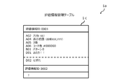
- FIG. 7 is a schematic diagram showing an example of the evaluation information management table in this embodiment.
- FIG. 8 is a flow chart showing an example of the operation of the dynamic two-dimensional code evaluation system in this embodiment.
- FIG. 9 is a schematic diagram showing an example of the overall configuration of the dynamic two-dimensional code evaluation system in this embodiment.
- JIS standard Japanese Industrial Standard JISX05102004 “two-dimensional code symbol-QR code (registered trademark)-” (hereinafter, may be simply referred to as “JIS standard”) or ISO.
- an encoder that can handle non-public (hidden) private datacode words (non-public information) is called an extended encoder (not shown), and a decoder is called an extended decoder.
- the dynamic two-dimensional code evaluation system may be configured by the extension encoder and the extension decoder.
- the two-dimensional code is a two-dimensional code that can record public information and non-public information (such a two-dimensional code is called an extended two-dimensional code.
- the public information is information that can be read by a JIS standard decoder (standard decoder).
- the non-public information is information that cannot be read by the standard decoder and can be extracted only by the extended decoder.
- code word is described as having a length of 8 bits, but it may be a length of 16 bits or have another length such as a length of 1 bit depending on the system. Can also
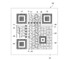
- FIG. 1 is an explanatory diagram of the two-dimensional code 40 (two-dimensional code symbol).
- the two-dimensional code 40 (hereinafter, may be simply referred to as “QR code (registered trademark)”) is available in various sizes from 1 type to 40 type, but here, as an example, the model number “2” is used. Each function will be described by way of example.
- the two-dimensional code 40 has a functional pattern and a coding area.
- the functional pattern is a pattern necessary for searching the symbol position and identifying the characteristic of the two-dimensional code 40 necessary to assist the decoding of the two-dimensional code 40 in the module.
- the coding area is an area in which necessary information is written.
- the functional pattern has a position detection pattern FP, a separation pattern SP, a timing pattern TP, an alignment pattern AP, and a quiet zone QZ.
- the position detection pattern FP is a pattern arranged in at least three corners of the two-dimensional code 40. By identifying the three position detection patterns FP during reading, the direction and position of the code symbol of the two-dimensional code 40 can be correctly recognized.
- the patterning pattern SP is a 1-module-wide bright module arranged around the position detection pattern FP.
- the position detection pattern FP can be distinguished from the code symbol of the two-dimensional code 40.
- the module M is a unit cell that forms a code symbol of the two-dimensional code 40. In principle, 1 bit corresponds to 1 module.
- a group of a plurality of modules M, which are unit cells forming the two-dimensional code 40, is referred to as a module group.
- the timing pattern TP is a pattern in which one dark module and one bright module are linearly arranged alternately. Since the number of modules of the code symbol of the two-dimensional code 40 can be recognized by the timing pattern TP, the model number of the two-dimensional code 40 can be identified by this.
- the alignment pattern AP is a pattern arranged at a position determined by the model number of the two-dimensional code 40. In the case of a large module, the alignment pattern AP functions to assist the search for the position of the two-dimensional code 40.
- the quiet zone QZ is a bright module area with a minimum width of 4 modules that is provided around the authentication information 0.
- the coding area has a data code word, an error correction code word (hereinafter sometimes simply referred to as “correction code word”), and format information FI. Further, in the above description, each function is described by taking the model number “2” as an example. For example, model number information (VI: Version Information) is added to a large model number.
- the format information FI has information of an error correction level and a standard mask pattern (mask pattern defined by JIS standard).
- the standard mask pattern has display patterns of eight types (0 to 7) of masks, and one of the pattern numbers is set. Depending on the set pattern number, variations in black and white dots forming the two-dimensional code 40 are displayed.
- Data code words and error correction code words are data representing information and error correction code words for error correction when data cannot be read, and these are arranged.
- the format information has information about an error correction level applied to the two-dimensional code 40 and a standard mask pattern to be used, and becomes a coding pattern necessary for decoding the coding area.
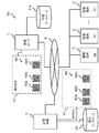
- FIG. 2 is a block diagram showing the overall configuration of the dynamic two-dimensional code evaluation system 50 in the first embodiment.
- the dynamic two-dimensional code evaluation system 50 includes a management server 1.
- the management server 1 includes a management database 1a, and includes a venue device 2 and a plurality of customer terminals 3.
- the dynamic two-dimensional code evaluation system 50 is connected to the hall device 2, a plurality of customer terminals 3 and the like via the public communication network 4 (network).
- the customer terminal 3 images each of the plurality of two-dimensional codes 40 included in the two-dimensional code set 41 dynamically displayed by the venue device 2, evaluates the captured two-dimensional code 40, and confirms various information and services. Get offered.
- the dynamic two-dimensional code evaluation system 50 includes, for example, a plurality of two-dimensional code sets 41 included in the two-dimensional code set 41 generated by the management server 1 in a lottery of a target person or a product or a game at a facility such as an event venue or a live venue.
- the dimension codes 40 are sequentially displayed on the screen, display, etc. provided in the venue device 2.
- the display of a screen or a display is displayed at a speed of 300 milliseconds per frame, for example, as in a moving image, and a plurality of code symbols, such as a moving image, are dynamically displayed as time passes. May be displayed.
- the venue device 2 is connected to the management server 1.
- the management server 1 permits access from the venue device 2, and sets a plurality of two-dimensional codes 40 included in the two-dimensional code set 41 stored in the management database 1a in advance by setting information set by an administrator or the like.
- the evaluation information is transmitted to the customer terminal 3, and the customer terminal 3 captures an image of the two-dimensional code 40 that is sequentially displayed on the screen, the display, or the like provided in the hall device 2.
- the result of the image pick-up at the customer terminal 3 includes a combination of installation information set in advance for the two-dimensional code set 41 and, as described above, a display at a speed of 300 milliseconds per frame, etc. It is possible to display different results depending on the information of the owner of the customer terminal 3 and the state of the customer terminal 3 (for example, imaging specifications, imaging timing, etc.).
- the management server 1, the two-dimensional code set 41 or the two-dimensional code 40 distributed in advance to related parties, staff, customers, etc., is, for example, various information such as held events and live performances, and various related parties.
- the two-dimensional code set 41 is generated on the basis of various information such as roles and characteristics of staff, customers and the like, profiles, functions and specifications of the customer terminal 2 owned.
- the management server 1 transmits the generated two-dimensional code set 41 or the two-dimensional code 40 to the hall device 2.
- the management server 1 refers to the destination information of the related persons, staff, customers, etc. stored in the management database 1a and transmits the generated two-dimensional code set 41 or two-dimensional code 40.
- the two-dimensional code set 41 or the two-dimensional code 40 generated by the management server 1 is electronically generated and, for example, one piece of the two-dimensional code 40 is fixedly displayed on a printed matter or a package as an evaluation target. It may be generated (printed or printed) in a state.
- the two-dimensional code set 41 or the two-dimensional code 40 generated by the management server 1 is used as URL information for displaying on the customer terminal 3 at each distribution destination (for example, related persons, staff, customers, etc.), It is written and sent by sending means such as electronic mail or mail.
- the venue device 2 stores the two-dimensional code set 41 received from the management server 1 in the display database 2a of the venue device 2, and displays a plurality of two-dimensional code 40 based on the setting information from the stored two-dimensional code set 41. You may do so.
- the venue device 2 includes a screen or a display (not shown) that displays the two-dimensional code 40 (two-dimensional code 40a, two-dimensional code 40b, two-dimensional code 40n, etc.) included in the two-dimensional code set 41.
- an imaging device such as a camera that discriminates the two-dimensional code set 41 or the two-dimensional code 40 that is distributed in advance to parties, staff, customers, etc. who come in and out of the hall (Fig. (Not shown) may be provided at the entrance and exit doors and gates. Therefore, the hall apparatus 2 can capture an image of the two-dimensional code set 41 or the two-dimensional code 40 distributed in advance to the related persons, staff, customers, etc. by the image capturing apparatus provided at the door or the gate. As a result, it is possible to prevent falsification and forgery of various tickets and the like.
- the customer terminal 3 holds a plurality of two-dimensional codes 40 which are held by the customer (photographer or imager) and are sequentially displayed on the screen or display of the event venue or live venue, for example. An image is taken by the imaging function or application provided in the terminal 3.
- the two-dimensional code 40 captured by the customer terminal 3 may be sequentially stored in a storage unit of the customer terminal 3 described later, or may be stored in a storage unit (not shown) allocated on the cloud. Good.
- the customer terminal 3 stores one two-dimensional code 40 imaged (selected) by the customer terminal 3 from the two-dimensional code set 41 dynamically displayed, for example, at a specific or arbitrary timing. May be.
- the customer terminal 3 can efficiently store the memory of the customer terminal 3 by storing the two-dimensional code 40 at a specific or arbitrary timing.
- the customer terminal 3 receives the two-dimensional code set 41 from the management server 1, displays the received two-dimensional code set 41, and displays it on the entrance and exit doors and gates of the venue device 2.
- the image may be captured by a provided imaging device or a terminal used by a person involved in the event or live performance, staff, or the like.
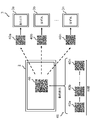
- the two-dimensional code 40 included in the two-dimensional code set 41 displayed on the venue device 2 is, for example, as shown in FIG. 3, as a plurality of two-dimensional codes 40a to 40n over time, as shown in FIG.
- the image is captured by the customer terminal 3.
- the dynamic display is, for example, displayed as if the plurality of two-dimensional codes 40a to 40n two-dimensional code 40 are rotating.
- Each of the customer terminals 3a to 3n images the two-dimensional code 40 dynamically displayed on the hall apparatus 2.
- the dynamically displayed two-dimensional code 40 is a set of two-dimensional codes 40a to 40n that are dynamically displayed on the venue device 2.
- Each of the two-dimensional codes 40a to 40n imaged by each of the customer terminals 3a to 3n is evaluated by each of the customer terminals 3a to 3n, and the respective configuration information of the two-dimensional codes 40a to 40n at the time of imaging
- the corresponding display (“win!”, “out”) is displayed on the customer terminals 3a to 3n.
- FIG. 4 is a schematic diagram showing an example of the configuration of the customer terminal 3 (customer terminal 3a, customer terminal 3b, customer terminal 3c).
- the customer terminal 3 in addition to a personal computer (PC), an electronic device such as a smartphone or a tablet terminal is used.
- the customer terminal 3 includes a housing 10, a CPU (Central Processing Unit) 100, a ROM (Read Only Memory) 101, a RAM (Random Access Memory) 102, a storage unit 103, and I/Fs 104 to 106. ..
- the components 100 to 106 are connected by an internal bus 107.
- the CPU 100 controls the entire customer terminal 3.
- the ROM 101 stores the operation code of the CPU 100.
- the RAM 102 is a work area used when the CPU 100 operates.
- the storage unit 103 stores various kinds of information such as setting information and evaluation information.
- As the storage unit 103 for example, an HDD (Hard Disk Drive), an SSD (solid state drive), or the like is used.
- the customer terminal 3 may have a GPU (Graphics Processing Unit) not shown. By having the GPU, it becomes possible to perform higher-speed arithmetic processing than usual.
- the I/F 104 is an interface for transmitting and receiving various types of information to and from the management server 1, the hall device 2, and the like via the public communication network 4.
- the I/F 105 is an interface for transmitting/receiving information to/from the input unit 109.
- a keyboard, a touch panel, or the like is used as the input unit 109, and a customer, an administrator, or the like who uses the dynamic two-dimensional code evaluation system 50 can input various information or control commands of the customer terminal 3 through the input unit 109. Enter or select.
- the I/F 106 is an interface for transmitting/receiving various information to/from the output unit 108.
- the output unit 108 outputs various information stored in the storage unit 103, the processing status of the customer terminal 3, and the like.
- a display is used as the output portion 108, and may be, for example, a touch panel type. In this case, the output part 108 may include the input part 109.
- FIG. 5 is a schematic diagram showing an example of the functions of the customer terminal 3.
- the customer terminal 3 includes, for example, a reception unit 20, an image pickup unit 21, an analysis unit 22, an evaluation unit 23, a control unit 24, an output unit 25, and a storage unit 26.
- Each function shown in FIG. 5 is realized by the CPU 100 executing a program stored in the storage unit 103 or the like using the RAM 102 as a work area. Further, each function may be controlled by artificial intelligence, for example.
- the "artificial intelligence" may be based on any known artificial intelligence technology.
- the receiving unit 20 analyzes the setting information for analyzing the plurality of two-dimensional codes 40 that are dynamically displayed on the venue device 2 and that constitutes the two-dimensional code set 41, and the customer terminal 3 or an external server (not shown). Receive evaluation information for evaluating the results of the evaluation. When outputting (displaying) the two-dimensional code set 41, the receiving unit 20 also receives the two-dimensional code set 41 generated based on the setting information. The two-dimensional code set 41 received by the receiving unit 20 is dynamically displayed based on the setting information.
- the setting information received by the receiving unit 20 is, for example, various setting information stored in advance in the management database 1a of the management server 1 and associated with the setting information ID registered in the setting information management table 1b.
- the evaluation information is, for example, various kinds of evaluation information associated with the evaluation information ID registered in the evaluation information management table 1c stored in advance in the evaluation information management table 1c.
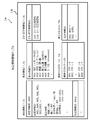
- FIG. 6 shows various types of information stored in the setting information management table 1b.
- the setting management information table 1b setting information for identifying or authenticating the two-dimensional code 40 to be imaged is stored in association with the two-dimensional code 40.
- the setting information ID is stored for each set of two-dimensional codes 40.
- the setting information ID is set as common setting information in the set of two-dimensional codes 40. Therefore, for example, if there are a plurality of two-dimensional codes 40 that are dynamically displayed, they are commonly set for all the two-dimensional codes 40 related to the dynamic display.
- the setting information table is generated by the management server 1, and the setting information table generated via the management server 1 is transmitted to the customer terminal 3.
- the setting information table transmitted to the customer terminal 3 is information to be locally analyzed by the customer terminal 3, and may be analyzed by the management server 1, for example.
- the setting information management table 1b received by the receiving unit 20 of the customer terminal 3 stores various information for analyzing and evaluating the two-dimensional code 40, for example. Items set in the setting information management table 1b are set by, for example, the administrator of the management server 1. Each item to be set is associated with, for example, a display information table, a standard mask pattern table, an error correction word information table, a configuration structure information table, and a display information table.
- Various setting information IDs set in the setting information management table 1b are determined by, for example, the manager or the organizer of the above-mentioned event or live, the holding scale of the event or live, the number of participants, the venue, In addition to the holding time, etc., it is appropriately set according to the conditions of the lottery, etc. Settings are based on various information such as past events and live events, number of participants, held questionnaire information, lottery results, and other past events such as history of events.
- the two-dimensional code 40 is set.
- the setting information ID is given to the plurality of two-dimensional codes 40 forming the two-dimensional code set 41 to be evaluated, and is set as, for example, “0001” or “0002”.
- the setting identified by each setting information ID is, for example, as setting information of the display information table, “A02 (direction)”, “A04 (display position)”, “A05 (display order)”, “A07 (image “Reversal of light and dark)”, “A07 (bright and dark colors forming the code)", and "A08 two-dimensional code type" are set.
- “B01 (Pattern 0)” is set as standard mask pattern table setting information
- “D01 (Public structure open/closed)”, “D02 (Structural connection)”, and “D03 read protection” are set as the structure information table.
- “D04 authentication structure” and display text information “E01 (around!)” and “E02 (out)” are set.
- the set information is information for setting the operation related to the dynamic display, and includes, for example, the number of the two-dimensional codes 40 constituting the two-dimensional code set 41 to be dynamically displayed, the presence/absence of the two-dimensional code 40 serving as the starting point of the evaluation.
- various items such as the number of base points, display time per dynamic display (or total time), coordinates of display position on the customer terminal 3 display or screen (X axis, Y axis), etc. Information is set.
- the base point may be dynamically set for each customer terminal 3.
- the various kinds of information set in the setting information table may be, for example, any one of the setting items, or all the setting items may be set as a combination.
- the setting of the combination may be appropriately selected and set, for example, by the organizer of the event, live performance, or the like, based on information such as the content and scale of the event, the characteristics of the target person, and customer benefits.
- the display information table includes, for example, "A01 (tilt: 1 degree to 360 degrees), “A02: direction (up/down/left/right)”, “A03: front and back sides which are mirror image inversions of code symbols. )”, “A04: display position (X axis, Y axis)”, “A05: display order (nth)”, “A06 (inversion of light and dark of image)”, “A07: light and dark colors forming code ( #Nnnnn)” and “A08 two-dimensional code type” are set. Which item is set with which value is arbitrary.
- the standard mask pattern table for example, eight types “B01 (pattern 0)” to “B08 (pattern 7)” are set as information indicating the standard mask pattern.
- the standard mask pattern is automatically determined based on the standard of the QR code (registered trademark), but which standard mask pattern is set is arbitrary and is combined with other setting information. It is possible to set it.
- the combination of the standard mask patterns is combined with, for example, the display direction (up/down/left/right) of the two-dimensional code 40, up to 32 different settings can be set. Therefore, any one of them or a combination of a plurality of them is an evaluation target of the two-dimensional code 40 that constitutes the two-dimensional code set 41 (for example, “A02: direction (upper)”, “B01 (pattern 2)”. Etc.).
- the error correction word information table can include specific information in the error correction word area before and after processing the error correction word, for example.
- This information is an area that is normally deleted after the processing of the error correction word, but by including the information in this area as an evaluation target, the two-dimensional code set 41 that is dynamically displayed is configured.
- the two-dimensional code 40 to be evaluated can be evaluated from the plurality of two-dimensional codes 40 to be evaluated.
- "C01 (before error correction processing)" and "C02 (after error correction processing)" are set as information indicating before and after processing of error correction words. Which is set as the area is arbitrary.
- the configuration structure information table can include, for example, at least one of the configuration structure of public/non-disclosure regarding the configuration structure of a specific code word of the two-dimensional code, structural connection, read protection, and authentication structure. is there.
- the disclosure/non-disclosure regarding the configuration structure of a specific code word of the two-dimensional code is, for example, in the case where the two-dimensional code 40 is not disclosed, the confidential data code of the two-dimensional code 40 is replaced with a part or all of the embedded code and the end identification. Include placement information after code. As a result, the secret data code placed after the terminal identification code is not read by the reading device of general specifications.
- the structural connection is provided by, for example, the above-mentioned JIS standard, indicates the connection state of the plurality of two-dimensional codes 40, and includes this information as the structural connection.
- the read protection is performed by, for example, performing a masking process using a standard mask pattern on the two-dimensional code 40 and performing a protection coding process on a code block by a protection coding pattern defined separately from the masking process.
- the standard reading means that does not know this convention or the protection encoding pattern cannot read the code because the configuration as a two-dimensional code cannot be established. Is included in the read information.
- the authentication structure includes, for example, related code information for identifying that a plurality of related two-dimensional codes 40 are related to each other in the confidential data code of the two-dimensional code 40. Includes information about the structure.
- FIG. 7 shows various information stored in the evaluation information management table 1c.
- the evaluation management information table 1c stores evaluation information for identifying or authenticating the captured two-dimensional code 40 from the two-dimensional code 40 forming the two-dimensional code set 41 that is dynamically displayed.
- the evaluation information management table 1c stores the evaluation information ID of the two-dimensional code 40 to be evaluated for each two-dimensional code set 41.
- One or a plurality of evaluation information IDs are set as evaluation information common to a plurality of two-dimensional codes 40 forming the two-dimensional code set 41. Therefore, for example, if there are a plurality of two-dimensional codes 40 that form the two-dimensional code set 41 that is dynamically displayed, all the two-dimensional codes 40 that are dynamically displayed are evaluated in common. What kind of evaluation is performed is arbitrary, and as described above, for example, it is possible to combine information regarding holding of events and live performances, information regarding venue equipment, information regarding the customer terminal 3 (customer), and the like.
- the various evaluation information IDs set in the evaluation information management table 1c are determined by, for example, the manager or the organizer of the above-mentioned event or live, and the holding scale of the event or live, the number of participants, the venue, In addition to the holding time, etc., it is appropriately set according to the conditions of the lottery, etc. Settings are based on various information such as past events and live events, number of participants, held questionnaire information, lottery results, and other past events such as history of events.
- the two-dimensional code 40 is set. The kind of display is arbitrary.
- the evaluation information ID is given to a set of a plurality of two-dimensional codes 40 to be evaluated, and is set as, for example, “0001” or “0002”.
- the setting identified by each evaluation information ID is, for example, “right” for “A02 (direction)”, “A04 (display) for each item set in the display information table described above as evaluation information.
- Position) "coordinates XXX, YYY”, “A05 (display order)" to "3”, "A07 (bright and dark colors forming the code)” to "#000000”, "A08” “Pattern 0” is set as evaluation information for “(two-dimensional code type)” and “B01 (standard mask pattern)”.
- the kind of display is arbitrary.
- the customer terminal 3 stores a display text as information to be displayed on the customer terminal 3 according to the evaluation result.
- "E01 (around!)” is stored as a display when it is evaluated that the evaluation conditions are matched
- "E02 (outlier)” is stored as a display when the evaluation conditions are not matched.
- the display text stored here may be, for example, still images such as illustrations and photographs, moving images, and audio data, in addition to the text information. What kind of content is displayed is arbitrary.
- the image capturing unit 21 captures the dynamically displayed two-dimensional code 40 displayed by the hall device 2.
- the image capturing unit 21 activates an image capturing function (camera function) provided in the customer terminal 3 or an image capturing application to capture an image.
- the imaging may be a still image or a moving image.
- the imaging unit 21 images the two-dimensional code set 41 or the two-dimensional code 40 and stores the image in the storage unit 103 of the customer terminal 3 or the storage unit 26 of the customer terminal 3 described later.
- the image capturing unit 21 When capturing the two-dimensional code set 41 or the two-dimensional code 40, the image capturing unit 21 also acquires various pieces of information related to the image capturing conditions such as the image capturing date and time and the image capturing location, and captures the image. It may be stored in the storage unit 103, the storage unit 26, or the like in association with each of the dimension codes 40.
- the analysis unit 22 analyzes the captured two-dimensional code set 41 or the two-dimensional code 40 based on the setting information.
- the analysis by the analysis unit 22 is performed by the management server 1 in addition to the customer terminal 3, for example, in the case where the customer terminal 3 cannot perform processing due to security reasons, the management server 1 receives the analysis result. It may be performed (not shown).
- the analysis unit 22 analyzes based on various setting information regarding the two-dimensional code set 41 or the two-dimensional code 40 received by the receiving unit 20.
- the management server 1, the hall apparatus 2, and the customer terminal 3 have previously decided on which setting information ID the analysis unit 22 will analyze the captured two-dimensional code set 41 or the two-dimensional code 40. May be.
- the customer selects the setting information ID set for the two-dimensional code set 41 or the two-dimensional code 40 to be imaged from the plurality of setting information IDs displayed via the customer terminal 3.
- the analysis unit 22 analyzes each setting of the two-dimensional code 40 based on the setting identified by the selected setting information ID.
- the analysis unit 22 based on the structure forming the imaged two-dimensional code set 41 or the two-dimensional code 40, the dynamically displayed state, or the change or order of the dynamically displayed two-dimensional code set 41,
- the setting information received by the receiving unit 20 is analyzed based on the setting items included therein.
- the analysis unit 22 compares, for example, the captured two-dimensional code set 41 or the two-dimensional code 40 and each setting information and setting information received in advance with the setting information included in the setting item.
- the setting items are, for example, "A01 (inclination: 1 degree to 360 degrees), "A02: direction (up/down/left/right)", “A03: front and back (a front/back) that is a mirror image inversion of the code symbol”.
- A04 display position (X axis, Y axis)
- A05 display order (nth number)
- A07 light and dark colors composing code (#nnnnnn)
- B01 pattern 0
- each setting item that constitutes the imaged two-dimensional code 40 and preset is compared with each setting information recorded in the setting information management table 1b.
- the analysis unit 22 compares, based on the setting information of the two-dimensional code set 41, whether it is the two-dimensional code set 41 or the two-dimensional code 40 that match in a specific setting item, and the two-dimensional code set imaged from those results. 41 or the two-dimensional code 40 is analyzed. For these setting items, a plurality of setting information can be set and analyzed.
- the analysis unit 22 is correct if there is no difference between the setting items that make up the captured two-dimensional code set 41 or the two-dimensional code 40, the setting information, and the setting items preset as the set information, based on the result of the analysis.
- the two-dimensional code set 41 or the two-dimensional code 40 to be evaluated is used. As a result, the two-dimensional code set 41 or the two-dimensional code 40 that may be falsified or forged can be distinguished, and the two-dimensional code set 41 or the two-dimensional code 40 to be evaluated can be excluded.
- the analysis unit 22 evaluates the two-dimensional code set 41. Alternatively, it is determined that the two-dimensional code 40 is not used, and the analysis process is ended, and the two-dimensional code set 41 or the two-dimensional code 40 that is dynamically displayed next is imaged.
- the analysis unit 22 uses the two-dimensional code set 41 or the two-dimensional code 40 stored in the storage unit 103 of the customer terminal 3 in addition to the two-dimensional code set 41 or the two-dimensional code 40 captured by the image capturing unit 21.
- the two-dimensional code set 41 or the two-dimensional code 40 read out may be analyzed.
- the two-dimensional code set 41 or the two-dimensional code 40 may be analyzed not only by the customer terminal 3 but also by an external server or the like (not shown).
- ⁇ Evaluation unit 23 When the evaluation unit 23 determines that the two-dimensional code set 41 or the two-dimensional code 40 to be evaluated is determined according to the result of the analysis by the analysis unit 22, the evaluation unit 23 further determines the evaluation information previously received by the reception unit 20. Based on the evaluation. Specifically, the evaluation unit 23 evaluates the condition of each setting information of the setting information analyzed by the analysis unit 22 based on each target information stored in the evaluation information management table 1c.
- the evaluation unit 23 refers to the evaluation information stored in the evaluation information management table 1c and, for example, “right” for “A02 (direction)” and “coordinates XXX, YYY” for “A04 (display position)”. , “A05 (display order)” to “3”, “A07 (light and dark colors that make up the code)” to "#000000”, and “B01 (standard mask pattern)” to "pattern” It is evaluated whether the evaluation information is set as “0” or the like, and if some or all of these evaluation conditions are matched, “E01 (around!)” is displayed on the output unit 25 of the customer terminal 3. To do. What is displayed is arbitrary, and other words or the like may be used.
- the evaluation unit 23 displays “E02 (out)” on the output unit 25 of the customer terminal 3, and the two-dimensional code 40 that is dynamically displayed next. Is imaged.
- the evaluation unit 23 reads the two-dimensional code set 41 or the two-dimensional code 40 analyzed by the analysis unit 22 into the storage unit 103 of the customer terminal 3, evaluates the read two-dimensional code set 41 or the two-dimensional code 40, The evaluation result is displayed on the output unit 25 of the customer terminal 3.
- imaging may be performed a plurality of times.
- the two-dimensional code set 41 can be dynamically displayed like a moving image.
- the analysis unit 22 appropriately performs analysis according to the image capturing by the image capturing unit 21, and the evaluation unit.
- the imaged two-dimensional code set 41 or a plurality of two-dimensional codes 40 may be evaluated by the evaluation by 23.
- Control unit 24 controls the reception unit 20, the imaging unit 21, the analysis unit 22, the evaluation unit 23, the output unit 25, and the storage unit 26 of the customer terminal 3.
- the output unit 25 outputs the analysis result by the analysis unit 22 and the evaluation result by the evaluation unit 23.
- the output unit 25 transmits the analysis result and the evaluation result to the output unit 108 via the I/F 106, and, for example, the analysis result or the evaluation result to the management server 1, the hall device 2, etc. via the I/F 104. May be sent.
- the output unit 25 may output various conditions such as setting information, for example.
- the storage unit 26 stores the setting information received by the receiving unit 20 and various pieces of evaluation information in the storage unit 103.
- the storage unit 26 retrieves various types of information such as the information tables stored in the storage unit 103 as necessary.
- the information table stores various kinds of information such as previously acquired past setting information and evaluation information.
- the management server 1 stores a database relating to various types of information as a management database 1a.
- a management database 1a for example, various information sent via the public communication network 4 is accumulated.
- a setting information management table 1b and an evaluation information management table 1c which will be described later, are stored, and information similar to that of the storage unit 103 is stored.
- Various information may be transmitted and received.
- the management server 1 may perform analysis processing based on, for example, a defect in the customer terminal 3, processing capacity or security of the customer terminal 3, or the amount of information of the two-dimensional code set 41 or the two-dimensional code 40 to be processed. A part or the whole may be processed by the analysis unit 22 (not shown).
- the venue device 2 has the same configuration as the customer terminal 3 described above (not shown), and an electronic device such as a personal computer (PC) is used.
- the output part 108 of the venue device 2 is equipped with, for example, a large-sized display or projector, and displays or projects the two-dimensional code set 41 or the two-dimensional code 40 at the event venue, the live venue, or the like as described above. There may be a plurality of large-sized displays and screens at event venues, live venues, etc.
- the two-dimensional code set 41 or the two-dimensional code 40 has the same two-dimensional code 40 sequentially displayed on each display or screen. It is controlled by the control unit 24 of the venue device 2 so as to be projected.
- the display and screen are targeted for the venue device 2, but may be, for example, a television screen or a game screen at home.
- the venue device 2 stores a database relating to various information regarding the two-dimensional code set 41 or the two-dimensional code 40 to be dynamically displayed as a display database 2a.
- the display database 2a stores, for example, various kinds of information transmitted via the public communication network 4.
- setting information regarding the display or projection of the two-dimensional code set 41 or the two-dimensional code 40 in the hall apparatus 2 is stored.
- the venue device 2 displays or projects the two-dimensional code set 41 or the two-dimensional code 40 based on the setting information stored in the display database 2a.
- Various kinds of information may be stored in the display database 2a, and various kinds of information may be transmitted/received to/from the management server 1 and the customer terminal 3 via the public communication network 4. Further, the management server 1 transmits and delivers as a moving image. May be done.
- the public communication network 4 is an internet network or the like to which the management server 1, the venue device 2, the customer terminal 3 and the like are connected via a communication circuit.
- the public communication network 4 may be configured by a so-called optical fiber communication network.
- the public communication network 4 is not limited to a wired communication network, but may be realized by a wireless communication network, and may also be a general ground wave, a radio wave for TV broadcasting such as satellite broadcasting.
- FIG. 8 is a flowchart showing an example of the operation of the dynamic two-dimensional code evaluation system 50 in this embodiment.
- the receiving unit 20 evaluates, for example, setting information for analyzing the two-dimensional code set 41 or the two-dimensional code 40 dynamically displayed on the venue apparatus 2 from the management server 1 and the analyzed result.
- the evaluation information for receiving is received (reception means S110).
- the receiving unit 20 stores, for example, various information in the setting information management table 1b stored in the management database 1a of the management server 1 or the two-dimensional code set 41 or the two-dimensional code 40 dynamically displayed in the venue device 2.
- the setting information associated with the related setting information ID, the set information, and the evaluation information of the evaluation information management table 1c are received, and each received information is stored in the storage unit 103.
- Imaging unit 21 images, for example, the two-dimensional code set 41 or the two-dimensional code 40 that is dynamically displayed on the venue device 2 (imaging unit S120).
- the imaging unit 21 sequentially images the dynamically displayed two-dimensional code set 41 or the two-dimensional code 40 and also dynamically displays a series of the two-dimensional code set 41 or the two-dimensional code 40 (the two-dimensional code 40a to The two-dimensional code 40n) is recorded as a moving image.
- the image capturing unit 21 may also acquire information such as the date and time when the image was captured, the location, and the person who captured the image, and store the information in the storage unit 103 or the like via the storage unit 26.
- the analysis unit 22 analyzes the imaged two-dimensional code set 41 or the two-dimensional code based on the setting information (analyzing means S130).
- the analysis unit 22 reads the setting information received in advance by the reception unit 20 and stored in the storage unit 103, and analyzes each piece of information forming the imaged two-dimensional code set 41 or two-dimensional code 40.
- the analysis of the two-dimensional code 40 in the analysis unit 22 may be performed not only by the customer terminal 3 but also by the management server 1, for example. In that case, the customer terminal 3 transmits the captured two-dimensional code 40 to the management server 1.
- the analysis unit 22 compares each setting item forming the captured two-dimensional code set 41 or the two-dimensional code 40 with the setting information received in advance. In addition, the analysis unit 22 compares, based on the set information, whether it is the specific two-dimensional code set 41 or the two-dimensional code 40, and if there is no difference in the preset setting items based on the analysis results, a correct evaluation is performed. The target two-dimensional code set 41 or the two-dimensional code 40 is used.
- the evaluation unit 23 evaluates the result of the analysis by the analysis unit 22 based on the evaluation information (evaluation means S140).
- the evaluation unit 23 reads the evaluation information previously received by the reception unit 20 and stored in the storage unit 103, is analyzed by the analysis unit 22, and is analyzed as the correct two-dimensional code set 41 or two-dimensional code 40 and the two-dimensional code set.
- the setting condition of each setting item of 41 or the two-dimensional code 40 is evaluated. If all of the setting conditions and the evaluation conditions are the same, the evaluation unit 23 displays, for example, "win! on the output unit 25 of the customer terminal 3. !! ”Is output, and if they do not match, “out” is output.
- FIG. 9 is a schematic diagram showing an example of the dynamic two-dimensional code evaluation system 50 according to the second embodiment.
- the customer terminal 3 (customer terminal 3a, customer terminal 3b to customer terminal 3n, etc.) has a two-dimensional code set 41 or a two-dimensional code 40 (two-dimensional code 40a, two-dimensional code 40a, The dimension code 40b, the two-dimensional code 40n, etc. are output (displayed), and the two-dimensional code set 41 or the two-dimensional code 40 (two-dimensional code 40) that is displayed for each customer terminal 3 on the imaging unit 21 (for example) provided in the venue apparatus 2 is displayed. This is the point where the dimension code 40a, the two-dimensional code 40b, and the two-dimensional code 40n) are imaged. The description of the same configurations as those described above will be omitted.
- the customer terminal 3 receives the two-dimensional code set 41 or the two-dimensional code 40 which the customer terminal 3 previously received from the management server 1 or the like and stored in the storage unit 26 of the customer terminal 3, and the read two-dimensional code set 41.
- the two-dimensional code 40 is displayed on the display or the like of the customer terminal 3 via the output unit 25 of the customer terminal 3.
- Each of the customer terminals 3 includes an output unit 25 that outputs a set of a plurality of two-dimensional codes, and the receiving unit 20 receives the setting information and the two-dimensional code set 41 generated by the setting information. After that, the output unit 25 dynamically displays the two-dimensional code set 41 based on the received setting information.
- an imaging unit 21 is provided at the entrance and exit doors and gates of the venue.
- the image capturing unit 21 is the same as the image capturing unit 21 of the customer terminal 3 described above, and captures an image of the two-dimensional code set 41 or the two-dimensional code 40, and based on the setting information and the evaluation information received from the management server 1.
- the analysis unit 22 analyzes the two-dimensional code set 41 or the two-dimensional code 40 of the customer terminal 3, and the evaluation unit 23 evaluates the analysis result based on the evaluation information to the imaged two-dimensional code set 41 or the two-dimensional code 40. Then, for example, authentication of a legitimate customer is performed.
- the setting information and the evaluation information received by the receiving unit 20 are, for example, according to the customer information such as the profile and characteristics of each customer, the content of the event or live event, the size of the venue, the facility, etc. It may be information generated in advance. Therefore, it is possible to capture an image of the two-dimensional code set 41 or the two-dimensional code 40 that is dynamically displayed according to the customer and the date and time (content) of the event. As a result, the customer can analyze and evaluate the two-dimensional code set 41 or the two-dimensional code 40 captured in real time at the venue, and can prevent the output by the falsified or forged two-dimensional code set 41 or the two-dimensional code 40. ..
- the setting information constitutes the inclination, the direction, the front and back that is the mirror image inversion of the code symbol, the display position, the display order, and the code regarding the display of the two-dimensional code set 41 or the two-dimensional code 40.
- the evaluation information is at least one of light and dark colors, and the evaluation information includes a tilt, a direction, a front and back that is a mirror image inversion of a code symbol, a display position, a display order, and a code regarding a display previously specified as an evaluation target. At least one of the light and dark colors, and the information is received. Therefore, the analysis and evaluation of the two-dimensional code set 41 or the two-dimensional code 40 imaged by the customer terminal 3 can be complicated.
- the two-dimensional code set 41 or the two-dimensional code 40 can be prevented. Further, since the operation and the display according to the analysis and evaluation can be finely set, the optimum display (message or the like) or privilege (coupon) can be given to each customer in advance.
- the two-dimensional code set 41 or the plurality of two-dimensional codes 40 is dynamically displayed so as to rotate clockwise around the center of the two-dimensional code 40, or is displayed vertically and horizontally.
- various evaluations and outputs can be associated with each other, which may lead to an increase in imaging opportunities when a customer participates in an event and an improvement in motivation.
- the receiving unit 20 changes the setting information and the evaluation information (tilt, direction regarding display of the two-dimensional code 40, front and back which is mirror image inversion of code symbol, display position, display order, and A combination of at least one of the light and dark colors forming the code is received in real time. Therefore, the received setting information and evaluation information can be reflected. As a result, it becomes possible to analyze and evaluate the two-dimensional code set 41 or the two-dimensional code 40 which is dynamically displayed in front of the eyes while being at the event or live venue, and is linked to the holding or progress of the event or live. You can check the output.
- the setting information is an identifier number related to a standard mask pattern of the two-dimensional code 40
- the evaluation information is an identifier number of a standard mask pattern that is specified in advance as an evaluation target. To receive. Therefore, it is further combined with at least one of the information regarding the inclination, the direction, the front and back that is a mirror image inversion of the code symbol, the display position, the display order, and the light and dark colors forming the code, regarding the display of the two-dimensional code 40. Is possible. As a result, the analysis and evaluation of the two-dimensional code set 41 or the two-dimensional code 40 captured by the customer terminal 3 can be complicated, and the tampering and forgery of the dynamically displayed two-dimensional code 40 can be prevented.
- the setting information can be an error correction word included in the two-dimensional code 40
- the evaluation information can be an error correction word specified in advance as an evaluation target. Therefore, the analysis and evaluation of the two-dimensional code 40 captured by the customer terminal 3 can be complicated. As a result, it is possible to prevent the dynamic alteration and forgery of the two-dimensional code 40.
- each means S110 to S140 is stored in a computer as each step (for example, reception step, imaging step, analysis step, evaluation step). It may be executed.
- the two-dimensional code 40 dynamically displayed as described above can be analyzed based on the setting information, and the analysis result can be evaluated based on the evaluation information.
- the organizer of an event or live performance can mass-produce the two-dimensional code 40 to be dynamically displayed, can be widely distributed as electronic data, and can be practically used.
- the dynamic two-dimensional code evaluation method is setting information for analyzing a set of a plurality of two-dimensional codes that are dynamically displayed, and evaluation information for evaluating the analyzed result.
- the means and the analysis result can be provided by the evaluation means that performs the evaluation means S140 that evaluates based on the evaluation information.
- the evaluation unit 23 may further associate other information with the customer terminal 3 (target person) set in the evaluation information table based on the evaluation result. This makes it possible to provide a different added value even between the customer terminals 3 that match the evaluation conditions.
- the analysis and evaluation are performed based on the setting information and the evaluation information, so that the code types of different standards can be mixed, for example.
- the two-dimensional code set 41 is dynamically displayed while the plurality of two-dimensional codes 40 are circulated, and the two-dimensional code set 41 is moved once (one loop) as in streaming distribution. It may be a target display. Furthermore, the start time of the dynamic display may be set and the dynamic display may be performed at the set time. These dynamic displays correspond to the content (for example, advertisements and advertisements) and other moving images (for example, promotional videos, notice videos, etc.) that are arranged and arranged by the organizer of the event or live. It may be attached and set.
- the venue device 2 may be, for example, a store terminal installed in a store or the like (not shown).
- the store terminal dynamically displays the predetermined two-dimensional code set 41 or the two-dimensional code 40, and the customer who visits the store takes an image with the imaging unit 21 of the customer terminal 3.
- the customer terminal 3 performs the above-described analysis and evaluation based on the captured two-dimensional code set 41 or the two-dimensional code 41, for example, based on the setting information and the evaluation information transmitted in advance by the store server.
- the evaluation result may be displayed.
- the evaluation result displayed on the customer terminal 3 may be, for example, coupon information valid in the store.
- the customer terminal 3 of the customer who has visited the store has a predetermined two-dimensional code set. 41 or the two-dimensional code 40 is dynamically displayed.
- the store terminal captures an image of the two-dimensional code set 41 or the two-dimensional code 40 that is dynamically displayed on the customer terminal 3, and performs the aforementioned analysis and evaluation based on the setting information and the evaluation information stored in advance, The evaluation result may be displayed.
- the evaluation result displayed on the shop terminal becomes, for example, customer authentication information, and it is possible to confirm whether or not the customer is a legitimate registered customer.
- the management server 1 transmits the two-dimensional code set 41 or the two-dimensional code 40 to the customer terminal 3a, and the customer terminal 3a displays the received two-dimensional code set 41 or the two-dimensional code 40.
- the two-dimensional code set 41 or the two-dimensional code 40 dynamically displayed on the customer terminal 3a is imaged and analyzed and evaluated based on the setting information and the evaluation information to evaluate.
- the results are displayed on the customer terminals 3b to 3n. Since the points can be exchanged and the gifts can be transmitted through the two-dimensional code set 41 and the two-dimensional code 40 that are dynamically displayed through the respective customer terminals 3, it is possible to confirm the person who is the requester or the requestee and various It is possible to prevent falsification and forgery of tickets, etc.
- the two-dimensional code set 41 generated by the management server 1 may be used as a one-time password generation device that displays valid numbers in synchronization with the management server or the like. Good (not shown).
- a valid number is generated on the display unit of the one-time password generation device so that it changes over time, and this is used as a password for authentication. If the generator and the authenticator do not share the same secret, the so-called "answer synchronization" cannot be achieved.
- the generated valid number is displayed.For example, by recording the displayed valid number and using the recorded number as another input value, spoofing login etc. is possible. Become.
- the display pattern of the two-dimensional code set 41 or the two-dimensional code 40 that is dynamically displayed cannot record a display pattern and is dynamically changed. Of these, I cannot understand which two-dimensional code 40 is correct.
- the dynamically displayed two-dimensional code set or two-dimensional code 40 can be appropriately imaged on the reading side, and the imaged image may be analyzed and evaluated via the management server 1, for example. With such a configuration, for example, it is possible to disperse the processing and load related to analysis and evaluation, ensure security, and realize efficient processing.
- the customer terminal 3 may be evaluated by a combination of the dynamically displayed two-dimensional code set 41 and another two-dimensional code 40 not shown (for example, printed on a paper medium). ..
- the customer captures an image of the two-dimensional code 40 distributed in advance via the customer terminal 3, and by combining the evaluation result of the captured two-dimensional code 40 and the two-dimensional code set 41 captured thereafter,
- the two-dimensional code 40 to be evaluated may be evaluated from the dynamically displayed two-dimensional code set 41.
- one of the two-dimensional codes 40 may be evaluated from the dynamically displayed two-dimensional code set 41, and the two-dimensional code 40 specified by the evaluated two-dimensional code 40 may be evaluated. .. With such a configuration, it is possible to operate authentication using the two-dimensional code 40 that is not easily tampered with or forged.
- the two-dimensional code 40 is also applied to code symbols of various two-dimensional codes such as DataMatrix (registered trademark) or PDF417 in addition to the QR code (registered trademark). It is possible.
- the two-dimensional code standard is defined by the JIS standard in Japan and the ISO standard internationally, for example.
- the two-dimensional code is, for example, JIS X 0510:2004 two-dimensional code symbol-QR code (registered trademark)-, ISO/IEC 18004:2000, Information Technology-Automatic identification and datacapacitytechniquecodes-Benchmarking-Body code-R-code. Are known.
- JIS X 0512 2015 Information technology-Automatic recognition and data acquisition technology-Barcode symbol system specification-Data matrix, ISO/IEC 16022:2006, Information technology-Automatic identification data-capacity.
- Matrix bar code symbology specification etc. are known.
- PDF417 code for example, JIS X 0508:2010 barcode symbol system specification-PDF417, ISO/IEC 15438:2006, Information technology-identification proficiency and datacapacity technology4 data-capacity technology4.
- management server 1a management database 1b: setting information management table 1c: evaluation information management table 10: case 100: CPU 101: ROM 102: RAM 103: Storage unit 104 to 106: I/F 107: Internal bus 108: Output part 109: Input part 2: Venue device 2a: Display database 20: Reception part 21: Imaging part 22: Analysis part 23: Evaluation part 24: Control part 25: Output part 26: Storage part 3: Customer terminal 3a: Customer terminal 3b: Customer terminal 3c: Customer terminal 3n: Customer terminal 4: Public communication network 40: Two-dimensional code 40a: Two-dimensional code 40b: Two-dimensional code 40n: Two-dimensional code 41: Two-dimensional code set 50: Dynamic two-dimensional code evaluation system S110: Receiving means S120: Imaging means S130: Analyzing means S140: Evaluation means
Abstract
【課題】動的に変化して一連表示される複数枚の二次元コードを用いた動的二次元コード評価方法、動的二次元コード評価システム、及び、動的二次元コード評価プログラムを提供する。 【解決手段】動的表示される複数の二次元コード40の集合を分析するための設定情報と、分析された結果を評価するための評価情報とを受信する受信部20と、動的表示される二次元コード40を撮像する撮像部21と、撮像した二次元コード40を設定情報に基づいて分析する分析部22と、分析部22による分析の結果を、評価情報に基づいて評価する評価部23手段と、を備える。
Description
本発明は、動的二次元コード評価方法、動的二次元コード評価システム、及び動的二次元コード評価プログラムに関する。
一次元コードは、配置された明暗の帯がある方向の線状の軸上において変化するコードシンボルであり、バーコードとして一般的に知られている。二次元コードは、配置された明暗の点(ドット)や単位領域(モジュール)が、縦横のX軸とY軸で定められる平面上において変化する二次元のコードシンボルであり、例えば、QRコード(登録商標)、DataMatrix(登録商標)、又はPDF417など、多様なコードシンボルが存在する。
例えば、二次元コードを使ったシステムでは、複数の二次元コードを同一画面上に表示し、表示された二次元コードの読み取る順番でユーザ認証を行うシステム(例えば、特許文献1参照)や、二次元コードのコードシンボルの形式を3次元化させ、格納する情報量を多くし、立体的にすることで二次元コードよりセキュリティ性能を強化させる装置(例えば、特許文献2参照)が知られている。
特許文献1に開示されたシステムは、表示されたn×m個の二次元コードは、ユーザが読取装置を操作し、所定の数(m)の読取データを連ねた正しいm個の二次元コードそれぞれを、記憶手段に記憶された配置位置と同じ順番で読み取ることで、認証サーバの認証手段において、ユーザ認証が可能となる。
しかしながら、同一画面上に複数の二次元コードが表示された場合、一般的な読取装置では、読み取り範囲に入った二次元コードを自動的に読み取ってしまう。そのため、読取装置と二次元コードとの間に距離がある場合や、表示装置の表示面積が狭い場合は、誤った二次元コードを読み取ってしまい、正しく認証されないことがある。また、固定画像のため、コピーが容易にできてしまい、改ざんや偽造される危険性がある。
特許文献2に開示された装置は、高さの異なるコードパーツにより構成されている三次元コードを、コードパーツの高さ方向に結像面を変えながら複数回撮影して、画像データを取得し、取得した画像データを合成することで三次元コードの情報を読み取る。
しかしながら、三次元化のため、立体的にコードを形成する必要があり、すでに広く普及している一般的な二次元コードを使った電子表示には不向きであり、市場性を考慮した大量生産性や、電子データとして流通できず、実用的な問題があった。また、立体的なコードそのものは固定物であり、複製可能であることから改ざんや偽造される危険性がある。
そこで本発明は、上述した問題点に鑑みて案出されたものであり、その目的とするところは、動的に変化して一連表示される複数枚の二次元コードを用いた動的二次元コード評価方法、動的二次元コード評価システム、及び動的二次元コード評価プログラムを提供することにある。
第1発明に係る動的二次元コード評価方法は、動的表示される複数の二次元コードの集合を分析するための設定情報と、分析された結果を評価するための評価情報とを受信する受信ステップと、前記動的表示される二次元コードを撮像する撮像ステップと、前記撮像した二次元コードを前記設定情報に基づいて分析する分析ステップと、前記分析ステップによる分析の結果を、前記評価情報に基づいて評価する評価ステップと、を備えることを特徴とする。
第2発明に係る動的二次元コード評価方法は、第1発明において、前記設定情報は、前記二次元コードの表示に関する方向、コードシンボルの鏡像反転である裏表、表示位置、表示順番、画像の明暗の反転、コードを構成する明暗の色、二次元コードの種類、及び、二次元コードの形式情報の少なくとも何れかの情報を含み、前記評価情報は、評価対象として予め特定される前記表示に関する方向、コードシンボルの鏡像反転である裏表、表示位置、表示順番、コードを構成する明暗の色、二次元コードの種類、及び、二次元コードの形式情報の少なくとも何れかの情報であることを特徴とする。
第3発明に係る動的二次元コード評価方法は、第1発明又は第2発明において、前記設定情報は、前記二次元コードの標準マスクパターンに関する識別子番号を含み、前記評価情報は、評価対象として予め特定される前記標準マスクパターンの識別子番号を含むことを特徴とする。
第4発明に係る動的二次元コード評価方法は、第1発明~第3発明の何れかの発明において、前記設定情報は、前記二次元コードに含まれるエラー訂正語を含み、前記評価情報は、評価対象として予め特定されるエラー訂正語を含むことを特徴とする。
第5発明に係る動的二次元コード評価方法は、第1発明~第4発明の何れかの発明において、前記設定情報は、前記二次元コードを構成するデータコード語、及び訂正データコード語とからなるデータブロック構成コード語のうち、特定の位置にあるコード語を含み、前記評価情報は、評価対象として予め特定される前記二次元コードを構成するデータコード語、及び訂正データコード語とからなるデータブロック構成コード語のうち、特定の位置にあるコード語を含むことを特徴とする。
第6発明に係る動的二次元コード評価方法は、第1発明~第5発明の何れかの発明において、前記設定情報は、前記二次元コードの特定のコード語の構成構造に関する公開/非公開、構造的連接、読出し保護、及び認証構造の少なくとも何れかの構成構造を含み、前記評価情報は、評価対象として予め特定される前記二次元コードの特定のコード語の構成構造に関する公開/非公開、構造的連接、読出し保護、及び認証構造の少なくとも何れかの構成構造を含むことを特徴とする。
第7発明に係る動的二次元コード評価方法は、第1発明~第6発明の何れかの発明において、前記複数の二次元コードの集合を出力する出力ステップをさらに備え、前記受信ステップは、前記設定情報と、前記設定情報により生成された二次元コードの集合とを受信し、前記出力ステップは、前記受信した設定情報に基づき、前記二次元コードの集合を動的に表示すること、を特徴とする。
第8発明に係る動的二次元コード評価システムは、動的表示される複数の二次元コードの集合を分析するための設定情報と、分析された結果を評価するための評価情報とを受信する受信手段と、前記動的表示される二次元コードを撮像する撮像手段と、前記撮像した二次元コードを前記設定情報に基づいて分析する分析手段と、前記分析ステップによる分析の結果を、前記評価情報に基づいて評価する評価手段と、を備えることを特徴とする。
第9発明に係る動的二次元コード評価プログラムは、動的表示される複数の二次元コードの集合を分析するための設定情報と、分析された結果を評価するための評価情報とを受信する受信ステップと、前記動的表示される二次元コードを撮像する撮像ステップと、前記撮像した二次元コードを前記設定情報に基づいて分析する分析ステップと、前記分析ステップによる分析の結果を、前記評価情報に基づいて評価する評価ステップと、をコンピュータに実行させることを特徴とする。
第1発明~第7発明によれば、受信ステップは、動的表示される複数の二次元コードの集合を分析するための設定情報と、分析された結果を評価するための評価情報を受信する。このため、撮像フレームごとに、撮像された二次元コードのコードシンボルを分析できる。これにより、動的表示される複数の二次元コードに対応しコードシンボルの読み取りが可能となり、大量生産できる電子データとして広く流通でき、実用的な運用が可能となる。また、時間の経過と共に、動画のように複数個のコードシンボルが、次々と動的に表示することが可能となる。
また、第1発明によれば、撮像ステップは、動的表示される二次元コードを撮像する。このため、時間とともに変化する動的コードを読み取ることができる。これにより、コピーが困難で、改ざんや偽造がされにくい動的な二次元コードを認識することができる。さらに、一般的な二次元コードを使用しているので、実用性が高い。
また、第1発明では、分析ステップと評価ステップを備える。このため、動的表示される複数の二次元コードの集合を二次元コードのコード生成技法を組み合わせた二次元コードを分析し、評価情報に基づいて評価することができる。これにより、撮像前の二次元コードの集合の設定、撮像後の二次元コードの集合、または二次元コードの評価を複雑にでき、動的表示される二次元コードの改ざんや偽造を防止できる。
また、第2発明によれば、設定情報は、二次元コードの表示に関する傾き、方向、コードシンボルの鏡像反転である裏表、表示位置、表示順番、画像の明暗の反転、コードを構成する明暗の色、二次元コードの種類、及び、二次元コードの形式情報の少なくとも何れかの情報を含む。このため、これらの組み合わせにより、動的表示される複数の二次元コードを様々な組み合わせのパターンで表示することができる。これにより、撮像前の二次元コードの集合の設定、撮像後の二次元コードの集合、または二次元コードの評価を複雑にでき、動的表示される二次元コードの改ざんや偽造を防止できる。
また、第3発明によれば、設定情報は、二次元コードの標準マスクパターンに関する識別子番号を含む。このため、動的表示される複数の二次元コードの集合を、二次元コードのコード生成技法と用いて組み合わせることができる。これにより、撮像前の二次元コードの集合の設定、撮像後の二次元コードの集合、または二次元コードの評価を複雑にでき、複数の二次元コードが複製されたとしても、動的表示される二次元コードの改ざんや偽造を防止できる。
また、第4発明によれば、設定情報は、二次元コードに含まれるエラー訂正語を含む。このため、動的表示される複数の二次元コードの集合を、二次元コードのコード生成技法と組み合わせることができる。これにより、撮像前の二次元コードの集合の設定、撮像後の二次元コードの集合、または二次元コードの評価を複雑にでき、二次元コードが複製されたとしても、動的表示される二次元コードの改ざんや偽造を防止できる。
また、第5発明によれば、設定情報は、データブロック構成コード語のうち、特定の位置にあるコード語を含む。このため、動的表示される複数の二次元コードの集合を、データコード生成技法と組み合わせることができる。これにより、撮像前の二次元コードの集合の設定、撮像後の二次元コードの集合、または二次元コードの評価を複雑にでき、二次元コードが複製されたとしても、動的表示される二次元コードの改ざんや偽造を防止できる。
また、第6発明によれば、設定情報は、特定のコード語の構成構造を含む。このため、動的表示される複数の二次元コードの集合を、データコード生成技法と組み合わせることができる。これにより、撮像前の二次元コードの集合の設定、撮像後の二次元コードの集合、または二次元コードの評価を複雑にでき、二次元コードが複製されたとしても、動的表示される二次元コードの改ざんや偽造を防止できる。
また、第7発明によれば、受信ステップは、設定情報と、前記設定情報により生成された二次元コードの集合とを受信する。このため、設定情報を分析し、二次元コードの集合を動的に出力(表示)することができる。これにより、二次元コードの認証を複雑にでき、動的表示される二次元コードの改ざんや偽造を防止できる。
第8発明によれば、受信手段は、動的表示される複数の二次元コードの集合を分析するための設定情報と、分析された結果を評価するための評価情報を受信する。このため、撮像フレームごとに、撮像された二次元コードのコードシンボルを分析できる。これにより、動的表示される複数の二次元コードに対応しコードシンボルの読み取りが可能となり、大量生産できる電子データとして広く流通でき、実用的な運用が可能となる。
第9発明によれば、受信ステップは、動的表示される複数の二次元コードの集合を分析するための設定情報と、分析された結果を評価するための評価情報を受信する。このため、撮像フレームごとに、撮像された二次元コードのコードシンボルを分析できる。これにより、動的表示される複数の二次元コードに対応しコードシンボルの読み取りが可能となり、大量生産できる電子データとして広く流通でき、実用的な運用が可能となる。
以下、本発明を適用した実施形態における動的二次元コード評価システムの一例について、図面を参照しながら説明する。
図1を参照して、本実施形態における二次元コードシンボルの構成の一例について説明する。
<本実施の形態に係る二次元コードの一例について>
先ず、本実施形態で用いられる二次元コードの一例としてのQRコード(登録商標)について説明する。なお、以下の説明で特段のことわりのない場合には、日本工業規格 JISX05102004 「二次元コードシンボル-QRコード(登録商標)-」(以下、単に「JIS規格」ということがある)、または、ISO/ISE規格18004 2015「Automatic identification and data capture techniques-QR Code bar code symbology specification」、ISO/IEC規格16022 2006「Information technology-Automatic identification and data capture techniques-Data Matrix bar code symbology specification.」、または、ISO/IEC規格15438 2015「Information technology-Automatic identification and data capture techniques-PDF417 bar code symbology specification」、に準ずる。また、これらのJIS規格、またはISO/ISE規格に準ずるエンコーダを標準エンコーダといい、 JIS規格、またはISO/ISE規格に準ずるデコーダを標準デコーダという。
先ず、本実施形態で用いられる二次元コードの一例としてのQRコード(登録商標)について説明する。なお、以下の説明で特段のことわりのない場合には、日本工業規格 JISX05102004 「二次元コードシンボル-QRコード(登録商標)-」(以下、単に「JIS規格」ということがある)、または、ISO/ISE規格18004 2015「Automatic identification and data capture techniques-QR Code bar code symbology specification」、ISO/IEC規格16022 2006「Information technology-Automatic identification and data capture techniques-Data Matrix bar code symbology specification.」、または、ISO/IEC規格15438 2015「Information technology-Automatic identification and data capture techniques-PDF417 bar code symbology specification」、に準ずる。また、これらのJIS規格、またはISO/ISE規格に準ずるエンコーダを標準エンコーダといい、 JIS規格、またはISO/ISE規格に準ずるデコーダを標準デコーダという。
また、非公開とされる(隠蔽される)非公開データコード語(非公開情報)を取り扱うことができるエンコーダを拡張エンコーダ(図示せず)といい、デコーダを拡張デコーダという。また、拡張エンコーダと拡張デコーダにより動的二次元コード評価システムが構成されてもよい。
拡張エンコーダと拡張デコーダにより動的二次元コード評価システムでは、二次元コードは、公開情報と非公開情報とを記録することができる二次元コード(このような二次元コードを拡張二次元コードということがある)を前提としている。公開情報は、JIS規格のデコーダ(標準デコーダ)で読み出し可能な情報である。一方、非公開情報は、標準デコーダでは読み出すことができず、拡張デコーダによってのみ抽出することが可能な情報である。
また、以下の説明において、「コード語」は、8ビット長として説明するが、システムに応じて、16ビット長とすることもできるし、1ビット長など他の長さを有するものとすることもできる。
図1は、二次元コード40(二次元コードシンボル)の説明図である。二次元コード40(以下、単に、「QRコード(登録商標)」ということもある)は、1型から40型まで様々なサイズが用意されているが、ここでは、一例として型番「2」を例に各機能について説明する。
二次元コード40は、機能パターンと符号化領域を有する。機能パターンは、二次元コード40のモジュール内での復号化を補助するために必要な二次元コード40のシンボル位置の検索や特性の識別に必要なパターンである。符号化領域は、必要となる情報が書き込まれている領域である。
機能パターンは、位置検出パターンFP、分離パターンSP、タイミングパターンTP、位置合わせパターンAP、および、クワイエットゾーンQZを有する。
位置検出パターンFPは、二次元コード40の少なくとも3つの隅に配置されるパターンである。読み取り時において、3つの位置検出パターンFPを識別することで、二次元コード40のコードシンボルの方向や位置を正しく認識可能とする。
分雛パターンSPは、位置検出パターンFPの周りに配置される1モジュール幅の明モジュールである。これにより、位置検出パターンFPを二次元コード40のコードシンボルから区別することができるようになる。
モジュールMは、二次元コード40のコードシンボルを構成する単位セルである。原則として、1ビットが1モジュールに相当する。なお、ここでは、二次元コード40を構成する単位セルであるモジュールMを複数集合させたものをモジュール群と呼ぶ。
タイミングパターンTPは、暗モジュールと明モジュールが1モジュールずつ直線状に交互に配置されたパターンである。タイミングパターンTPによって、二次元コード40のコードシンボルのモジュール数を認識可能となるため、これにより二次元コード40の型番を識別することができる。
位置合わせパターンAPは、二次元コード40の型番によって決められた位置に配置されるパターンである。位置合わせパターンAPは、大きなモジュールの場合、二次元コード40の位置の検索を補助する働きをする。
クワイエットゾーンQZは、認証情報0の周囲に設けられる最低4モジュール幅の明モジュール領域である。
符号化領域は、データコード語および誤り訂正コード語(以下、単に「訂正コード語」ということがある)と、形式情報FIを有する。また、上述では、一例として型番「2」を例に各機能について説明しており、例えば、型番の大きなものには、型番情報(VI:Version Information)が付加される。形式情報FIは、誤り訂正レベルと標準マスクパターン(JIS規格における規定のマスクパターン)の情報を有する。なお、二次元コード40の場合は、一般的には、標準マスクパターンは8種類(0~7)のマスクの表示パターンを有し、そのうちの何れかのパターン番号が設定される。設定されたパターン番号によって、二次元コード40を構成する白黒のドットのバラつきが表示される。
データコード語および誤り訂正コード語は、情報を表現するデータおよびデータが読み出せなかった場合の誤り訂正用の誤り訂正コード語であり、これらを配置する。形式情報は、二次元コード40に適用する誤り訂正レベルおよび使用する標準マスクパターンに関する情報を有し、符号化領域を復号化するのに必要な符号化パターンとなる。
(第1実施形態)
図2~図8を参照して、第1実施形態における動的二次元コード評価システム50の構成の一例について説明する。図2は、第1実施形態における動的二次元コード評価システム50の全体の構成を示すブロック図である。
図2~図8を参照して、第1実施形態における動的二次元コード評価システム50の構成の一例について説明する。図2は、第1実施形態における動的二次元コード評価システム50の全体の構成を示すブロック図である。
図2に示すように、動的二次元コード評価システム50は、管理サーバ1を備える。管理サーバ1は、管理データベース1aを備え、会場装置2と、複数の顧客端末3と、により構成される。動的二次元コード評価システム50は、公衆通信網4(ネットワーク)を介して、会場装置2、複数の顧客端末3等と接続される。顧客端末3は、会場装置2によって動的表示される二次元コード集合41に含まれる複数の二次元コード40を各々に撮像し、撮像した二次元コード40を評価し、各種の情報やサービスの提供を受ける。
動的二次元コード評価システム50は、例えば、イベント会場やライブ会場等の施設で対象者や商品の抽選やゲーム等で、管理サーバ1によって生成された二次元コード集合41に含まれる複数の二次元コード40を会場装置2に備わるスクリーンやディスプレイ等に順次に表示させる。スクリーンやディスプレイ等の表示は、例えば、動画のように、1フレーム300ミリ秒等の速度で表示されるほか、例えば時間の経過と共に、動画のように複数個のコードシンボルが、次々と動的に表示されるようにしてもよい。
会場装置2は、管理サーバ1と接続される。管理サーバ1は、会場装置2からのアクセスを許可し、管理データベース1aに格納されている二次元コード集合41に含まれる複数の二次元コード40を、予め管理者等によって設定される設定情報及び評価情報とともに顧客端末3に送信し、顧客端末3は、会場装置2に備わるスクリーンやディスプレイ等に順次に表示される二次元コード40を顧客端末3で撮像する。
顧客端末3における撮像の結果は、二次元コード集合41に対して予め設定された設置情報の組み合わせと、前述の通り、動画のように、1フレーム300ミリ秒等の速度による表示と、各々の顧客端末3の所有者の情報や顧客端末3の状態(例えば、撮像スペックや撮像のタイミング等)により、異なる結果が表示することが可能となる。
管理サーバ1は、関係者やスタッフ、顧客等に事前に配布等される二次元コード集合41または二次元コード40は、例えば、開催されるイベントやライブ等の各種の情報、及び各種の関係者やスタッフ、顧客等の役割や特性、プロフィール、所有する顧客端末2の機能やスペック等の各種の情報に基づいて、二次元コード集合41を生成する。
管理サーバ1は、生成された二次元コード集合41、または二次元コード40を、会場装置2に送信する。管理サーバ1は、管理データベース1aに格納される関係者やスタッフ、顧客等の送信先情報を参照し、生成した二次元コード集合41、または二次元コード40を送信する。
管理サーバ1で生成される二次元コード集合41、または二次元コード40は、電子的に生成されるほか、例えば、評価対象として1枚の二次元コード40が印刷物やパッケージ等に固定表示される状態で生成(印字や印刷)されてもよい。管理サーバ1で生成された二次元コード集合41、または二次元コード40は、各々の配布先(例えば、関係者やスタッフ、顧客等)に、顧客端末3に表示をさせるためのURL情報として、電子メールや郵送等の送付手段により表記され送信される。
会場装置2は、管理サーバ1から受信した二次元コード集合41を、会場装置2の表示データベース2aに格納し、格納した二次元コード集合41から、設定情報に基づいて複数の二次元コード40表示するようにしてもよい。
会場装置2は、二次元コード集合41に含まれる二次元コード40(二次元コード40a、二次元コード40b、二次元コード40n等)を表示するスクリーンやディスプレイ等(図示せず)を備える。
また、後述する会場装置2では、例えば、会場に出入りする関係者やスタッフ、顧客等に事前に配布等される二次元コード集合41、または二次元コード40を判別するカメラ等の撮像装置(図示せず)を入退場のドアやゲートに備えてもよい。このため、会場装置2は、このドアやゲートに備わる撮像装置により、関係者やスタッフ、顧客等に予め配布される二次元コード集合41または二次元コード40を撮像することができる。これにより、各種のチケット等の改ざんや偽造を防止できる。
顧客端末3は、顧客(撮影者または撮像者)が各々に保持し、例えば、イベント会場やライブ会場等のスクリーンやディスプレイ等に順次に表示される複数の二次元コード40を、その場で顧客端末3に備わる撮像機能やアプリケーションで撮像する。顧客端末3によって撮像された二次元コード40は、後述する顧客端末3の記憶部に逐次に格納されたり、又は、クラウド上に割り当てられる記憶部(図示せず)に格納されるようにしてもよい。さらに、顧客端末3は、例えば、特定、または任意のタイミングで、動的表示される二次元コード集合41から、顧客端末3によって撮像(選択)された1つの二次元コード40を格納するようにしてもよい。顧客端末3は、特定、または任意のタイミングで二次元コード40を格納することで、顧客端末3のメモリを効率的に記憶することができる。
また、後述する第2実施形態では、顧客端末3は、管理サーバ1から二次元コード集合41を受信し、受信した二次元コード集合41を表示し、会場装置2の入退場のドアやゲートに備わる撮像装置、またはイベントやライブの関係者やスタッフ等が使用する端末によって撮像させるようにしてもよい。
会場装置2に表示される二次元コード集合41に含まれる二次元コード40は、例えば、図3に示すように、時間の経過とともに複数の二次元コード40a~二次元コード40nとして、ある一定時間に顧客端末3によって撮像される。動的表示は、例えば、複数の二次元コード40a~二次元コード40n二次元コード40が、回転しているかのように表示される。顧客端末3a~顧客端末3nのそれぞれは、会場装置2に動的表示される二次元コード40を撮像する。
動的表示される二次元コード40は、会場装置2上で動的表示される二次元コード40a~二次元コード40nの集合である。顧客端末3a~顧客端末3nのそれぞれで撮像された二次元コード40a~40nのそれぞれは、それぞれの顧客端末3a~顧客端末3nで評価され、撮像した時点の二次元コード40a~40nの各構成情報と各顧客端末3a~顧客端末3nが予め受信する設定情報と評価情報に基づき、それぞれで対応する表示(『あたり!!』、『はずれ』)が、顧客端末3a~顧客端末3nにされる。
<顧客端末3>
図4は、顧客端末3(顧客端末3a、顧客端末3b、顧客端末3c)の構成の一例を示す模式図である。顧客端末3として、パーソナルコンピュータ(PC)のほか、スマートフォンやタブレット端末等の電子機器が用いられる。顧客端末3は、筐体10と、CPU(Central Processing Unit)100と、ROM(Read Only Memory)101と、RAM(Random Access Memory)102と、保存部103と、I/F104~106とを備える。各構成100~106は、内部バス107により接続される。
図4は、顧客端末3(顧客端末3a、顧客端末3b、顧客端末3c)の構成の一例を示す模式図である。顧客端末3として、パーソナルコンピュータ(PC)のほか、スマートフォンやタブレット端末等の電子機器が用いられる。顧客端末3は、筐体10と、CPU(Central Processing Unit)100と、ROM(Read Only Memory)101と、RAM(Random Access Memory)102と、保存部103と、I/F104~106とを備える。各構成100~106は、内部バス107により接続される。
CPU100は、顧客端末3全体を制御する。ROM101は、CPU100の動作コードを格納する。RAM102は、CPU100の動作時に使用される作業領域である。保存部103は、設定情報、評価情報等の各種情報が記憶される。保存部103として、例えばHDD(Hard Disk Drive)のほか、SSD(solid state drive)等が用いられる。なお、例えば、顧客端末3は、図示しないGPU(Graphics Processing Unit)を有してもよい。GPUを有することで、通常よりも高速演算処理が可能となる。
I/F104は、公衆通信網4を介して管理サーバ1、及び会場装置2等との各種情報の送受信を行うためのインターフェースである。
I/F105は、入力部分109との情報の送受信を行うためのインターフェースである。入力部分109として、例えばキーボードやタッチパネル等が用いられ、動的二次元コード評価システム50を利用する顧客や管理者等は、入力部分109を介して、各種情報又は顧客端末3の制御コマンド等を入力又は選択する。
I/F106は、出力部分108との各種情報の送受信を行うためのインターフェースである。出力部分108は、保存部103に保存された各種情報、又は顧客端末3の処理状況等を出力する。出力部分108として、ディスプレイが用いられ、例えばタッチパネル式でもよい。この場合、出力部分108が入力部分109を含む構成としてもよい。
図5は、顧客端末3の機能の一例を示す模式図である。顧客端末3は、例えば、受信部20と、撮像部21と、分析部22と、評価部23と、制御部24と、出力部25と、記憶部26とを備える。なお、図5に示す各機能は、CPU100が、RAM102を作業領域として、保存部103等に記憶されたプログラムを実行することにより実現される。また、各機能は、例えば、人工知能により制御されてもよい。ここで、「人工知能」は、いかなる周知の人工知能技術に基づくものであってもよい。
<受信部20>
受信部20は、会場装置2で動的表示され二次元コード集合41を構成する複数の二次元コード40を分析するための設定情報と、顧客端末3または外部サーバ等(図示せず)で分析された結果を評価するための評価情報を受信する。また、受信部20は、二次元コード集合41の出力(表示)を行う場合は、設定情報に基づいて生成された二次元コード集合41を合わせて受信する。受信部20によって受信された二次元コード集合41は、設定情報に基づいて動的表示される。
受信部20は、会場装置2で動的表示され二次元コード集合41を構成する複数の二次元コード40を分析するための設定情報と、顧客端末3または外部サーバ等(図示せず)で分析された結果を評価するための評価情報を受信する。また、受信部20は、二次元コード集合41の出力(表示)を行う場合は、設定情報に基づいて生成された二次元コード集合41を合わせて受信する。受信部20によって受信された二次元コード集合41は、設定情報に基づいて動的表示される。
受信部20が受信する設定情報は、例えば、管理サーバ1の管理データベース1aに予め格納され、設定情報管理テーブル1bに登録される設定情報IDに関係付けられる各種の設定情報である。評価情報は、例えば、評価情報管理テーブル1cに予め格納される評価情報管理テーブル1cに登録される評価情報IDで関係付けられる各種の評価情報となる。
<設定情報管理テーブル1b>
図6に、設定情報管理テーブル1bに格納される各種の情報を示す。設定管理情報テーブル1bには、撮像する二次元コード40の識別、または認証のための設定情報が、二次元コード40に対応して格納される。設定情報テーブルには、各二次元コード40の集合ごとに設定情報IDが格納される。設定情報IDは、二次元コード40の集合で共通の設定情報として設定される。そのため、例えば、動的表示される二次元コード40が複数あれば、その動的表示に関連する全ての二次元コード40に対して共通に設定される。
図6に、設定情報管理テーブル1bに格納される各種の情報を示す。設定管理情報テーブル1bには、撮像する二次元コード40の識別、または認証のための設定情報が、二次元コード40に対応して格納される。設定情報テーブルには、各二次元コード40の集合ごとに設定情報IDが格納される。設定情報IDは、二次元コード40の集合で共通の設定情報として設定される。そのため、例えば、動的表示される二次元コード40が複数あれば、その動的表示に関連する全ての二次元コード40に対して共通に設定される。
<設定情報テーブル>
設定情報テーブルは、管理サーバ1で生成され、管理サーバ1を介して生成された設定情報テーブルが顧客端末3に送信される。顧客端末3に送信される設定情報テーブルは、顧客端末3でローカルに分析されるための情報であり、例えば、管理サーバ1で分析されてもよい。顧客端末3の受信部20で受信した設定情報管理テーブル1bは、例えば、二次元コード40を分析、及び評価するための各種の情報が格納される。設定情報管理テーブル1bで設定される項目は、例えば、管理サーバ1の管理者等によって設定される。設定される各項目は、例えば、表示情報テーブル、標準マスクパターンテーブル、エラー訂正語情報テーブル、構成構造情報テーブル、表示情報テーブルによって、それぞれ対応付けられる。
設定情報テーブルは、管理サーバ1で生成され、管理サーバ1を介して生成された設定情報テーブルが顧客端末3に送信される。顧客端末3に送信される設定情報テーブルは、顧客端末3でローカルに分析されるための情報であり、例えば、管理サーバ1で分析されてもよい。顧客端末3の受信部20で受信した設定情報管理テーブル1bは、例えば、二次元コード40を分析、及び評価するための各種の情報が格納される。設定情報管理テーブル1bで設定される項目は、例えば、管理サーバ1の管理者等によって設定される。設定される各項目は、例えば、表示情報テーブル、標準マスクパターンテーブル、エラー訂正語情報テーブル、構成構造情報テーブル、表示情報テーブルによって、それぞれ対応付けられる。
設定情報管理テーブル1bに設定される各種の設定情報IDは、例えば、前述のイベントやライブ等の管理者や主催者などによって決められ、イベントやライブの開催規模、参加者の人数、開催地、開催時間等のほかに、抽選の条件等に応じて、適宜に設定される。設定は、例えば、過去のイベントやライブ等の開催、参加者数、開催アンケート情報、抽選結果等の、過去の開催履歴等の各種情報に基づいて、評価対象となる動的表示される複数の二次元コード40に設定される。
設定情報IDは、評価対象となる二次元コード集合41を構成する複数の二次元コード40に対して付与され、例えば、『0001』、『0002』、として設定される。各々の設定情報IDで識別される設定は、例えば、表示情報テーブルの設定情報として、『A02(方向)』、『A04(表示位置)』、『A05(表示順番)』、『A07(画像の明暗の反転)』、『A07(コードを構成する明暗の色)』、『A08 二次元コード種類』が設定される。さらに、標準マスクパターンテーブルの設定情報として、『B01(パターン0)』、構成構造情報テーブルとして、『D01(構成構造公開/非公開)』、『D02(構造的連接)』、『D03 読出し保護』、『D04 認証構造』、表示テキスト情報として、『E01(あたり!!)』、『E02(はずれ)』が設定されていることを示す。なお、エラー訂正語情報テーブルとしての設定は無いが、この場合は、このエラー訂正語情報は設定されなかったということを示すものであり、どの項目が設定されるかは任意である。
設定情報テーブルには、さらに、集合情報が設定される。集合情報は、動的表示に関する動作を設定する情報であり、例えば、動的表示する二次元コード集合41を構成する二次元コード40の枚数、評価の起点となる二次元コード40の有無、有りの場合は基点の枚数目、動的表示する1枚あたりの表示時間(または全体の総時間)、顧客端末3のディスプレイまたはスクリーン上の表示位置の座標(X軸、Y軸)等の各種の情報が設定される。なお基点は、顧客端末3毎に動的に設定されてもよい。
設定情報テーブルに設定される各種の情報は、例えば、各々の設定項目のいずれか1つの設定でもよく、または、全ての設定項目を組み合わせとして設定してもよい。組み合わせの設定は、例えば、イベントやライブ等の主催者等は、開催の内容や規模、対象者の特性や顧客特典等の情報に基づき、適宜に選択、設定するようにしてもよい。
表示情報テーブルには、例えば、『A01(傾き:1度~360度)、『A02:方向(上・下・左・右)』、『A03:コードシンボルの鏡像反転である裏表(表・裏)』、『A04:表示位置(X軸、Y軸)』、『A05:表示順番(n番)』、『A06(画像の明暗の反転)』、『A07:コードを構成する明暗の色(#nnnnnn)』、『A08 二次元コード種類』が設定される。どの項目が、どの値等で設定されるかは任意である。
標準マスクパターンテーブルには、例えば、標準マスクパターンを示す情報として、8種類『B01(パターン0)』~『B08(パターン7)』が設定される。一般的には、標準マスクパターンはQRコード(登録商標)の標準規格に基づいて、自動的に決定されてしまうが、どの標準マスクパターンを設定するかは任意であり、他の設定情報とともに組み合わせて設定することが可能となる。標準マスクパターンの組み合わせは、例えば、二次元コード40の表示方向(上・下・左・右)と組み合わせた場合は、最大で32種類の異なる設定が可能となる。そのため、このうちのいずれか1つ、または複数の組み合わせを、二次元コード集合41を構成する二次元コード40の評価対象(例えば、『A02:方向(上)』、『B01(パターン2)』等)としてもよい。
エラー訂正語情報テーブルには、例えば、エラー訂正語の処理の前後において、エラー訂正語の領域に特定の情報を含ませることが可能である。この情報は、本来であればエラー訂正語の処理の後は削除されてしまう領域であるが、この領域に情報を評価対象として含ませることで、動的表示される二次元コード集合41を構成する複数の二次元コード40の中から、評価対象の二次元コード40を評価することが可能となる。エラー訂正語情報テーブルには、エラー訂正語の処理の前後を示す情報として、『C01(エラー訂正処理前)』、『C02(エラー訂正処理後)』として設定される。どちらが領域として設定されるかは任意である。
構成構造情報テーブルには、例えば、二次元コードの特定のコード語の構成構造に関する公開/非公開、構造的連接、読出し保護、及び認証構造の少なくとも何れかの構成構造を含ませることが可能である。
二次元コードの特定のコード語の構成構造に関する公開/非公開は、例えば、非公開とする場合は、二次元コード40の秘匿データコードを、埋め草コードの一部または全部に代えて終端識別コードの後に配置に関する情報を含ませる。これにより、終端識別コードの後に配置された秘匿データコードは、一般仕様の読取装置では読み取りの対象にならない。また、構造的連接は、例えば、上述のJIS規格の標準により提供され、複数の二次元コード40の連接の状態を示し、この情報を構造的連接として含ませる。また、読出し保護は、例えば、二次元コード40に対して、標準マスクパターンによるマスク処理に加え、これとは別に定義される保護符号化パターンによって保護符号化処理をコードブロックに対して行って保護符号化コードブロックを求めることで、この規約や保護符号化パターンを知らない標準読取り手段においては二次元コードとしての構成が成り立たないためコードを読み取ることができなくなるといった処理であり、この処理に関する情報を読出し情報をして含ませる。認証構造は、例えば、複数の関連する二次元コード40が互いに関連付けられていることを特定可能とするための関連コード情報を、二次元コード40の秘匿データコードに含ませるものであり、この認証構造に関する情報を含ませる。
<評価情報管理テーブル1c>
図7に、評価情報管理テーブル1cに格納される各種の情報を示す。評価管理情報テーブル1cには、動的表示される二次元コード集合41を構成する二次元コード40から、撮像した二次元コード40の識別、または認証のための評価情報が格納される。評価情報管理テーブル1cには、二次元コード集合41毎に評価の対象となる二次元コード40の評価情報IDが格納される。評価情報IDは、二次元コード集合41を構成する複数の二次元コード40で共通の評価情報として、1つ、または複数が設定される。そのため、例えば、動的表示される二次元コード集合41を構成する二次元コード40が複数あれば、動的表示される全ての二次元コード40に対して共通に評価される。どのような評価にするかは任意であり、前述の通り、例えば、イベントやライブ等の開催に関する情報、会場の設備に関する情報、顧客端末3(顧客)に関する情報等との組み合わせが可能となる。
図7に、評価情報管理テーブル1cに格納される各種の情報を示す。評価管理情報テーブル1cには、動的表示される二次元コード集合41を構成する二次元コード40から、撮像した二次元コード40の識別、または認証のための評価情報が格納される。評価情報管理テーブル1cには、二次元コード集合41毎に評価の対象となる二次元コード40の評価情報IDが格納される。評価情報IDは、二次元コード集合41を構成する複数の二次元コード40で共通の評価情報として、1つ、または複数が設定される。そのため、例えば、動的表示される二次元コード集合41を構成する二次元コード40が複数あれば、動的表示される全ての二次元コード40に対して共通に評価される。どのような評価にするかは任意であり、前述の通り、例えば、イベントやライブ等の開催に関する情報、会場の設備に関する情報、顧客端末3(顧客)に関する情報等との組み合わせが可能となる。
評価情報管理テーブル1cに設定される各種の評価情報IDは、例えば、前述のイベントやライブ等の管理者や主催者などによって決められ、イベントやライブの開催規模、参加者の人数、開催地、開催時間等のほかに、抽選の条件等に応じて、適宜に設定される。設定は、例えば、過去のイベントやライブ等の開催、参加者数、開催アンケート情報、抽選結果等の、過去の開催履歴等の各種情報に基づいて、評価対象となる動的表示される複数の二次元コード40に設定される。どのような表示にするかは任意である。
評価情報IDは、評価対象となる複数の二次元コード40の集合に対して付与され、例えば、『0001』、『0002』、として設定される。各々の評価情報IDで識別される設定は、例えば、前述の表示情報テーブルに設定された各項目に対して、評価情報として、『A02(方向)』に対して『右』、『A04(表示位置)』に対して『座標XXX,YYY』、『A05(表示順番)』に対して『3番』、『A07(コードを構成する明暗の色)』に対して『#000000』、『A08(二次元コード種類) 』、『B01(標準マスクパターン)』に対して『パターン0』が、評価情報として設定される。どのような表示にするかは任意である。
顧客端末3は、評価結果に応じて顧客端末3上に表示させる情報として、表示テキストを記憶する。表示テキストは、評価条件に一致すると評価された場合の表示として『E01(あたり!!)』を記憶し、評価条件に一致しない場合の表示として『E02(はずれ)』を各々に記憶する。ここで記憶される表示テキストは、テキスト情報の他に、例えば、イラストや写真等の静止画像、動画や音声データであってもよい。どのようなコンテンツを表示させるかは任意である。
<撮像部21>
撮像部21は、会場装置2によって表示される動的表示される二次元コード40を撮像する。撮像部21は、例えば、顧客端末3に備わる撮像機能(カメラ機能)や撮像のアプリケーションを起動して撮像する。撮像は、静止画のほか、動画による撮影であってもよい。撮像部21は、二次元コード集合41または二次元コード40を撮像し、顧客端末3の保存部103または、後述する顧客端末3の記憶部26に格納する。
撮像部21は、会場装置2によって表示される動的表示される二次元コード40を撮像する。撮像部21は、例えば、顧客端末3に備わる撮像機能(カメラ機能)や撮像のアプリケーションを起動して撮像する。撮像は、静止画のほか、動画による撮影であってもよい。撮像部21は、二次元コード集合41または二次元コード40を撮像し、顧客端末3の保存部103または、後述する顧客端末3の記憶部26に格納する。
撮像部21は、二次元コード集合41または二次元コード40を撮像する際に、例えば、撮像日時、撮像場所等の撮像条件に関する各種情報を合わせて取得し、撮像した二次元コード集合41または二次元コード40の各々と関連付けて保存部103、または記憶部26等に格納してもよい。
<分析部22>
分析部22は、撮像した二次元コード集合41または二次元コード40を設定情報に基づいて分析する。分析部22による分析は、顧客端末3の他に、例えば、顧客端末3ではセキュリティの都合上、処理できないような分析の場合は管理サーバ1で分析が行われ、顧客端末3は分析結果を受信するようにしてもよい(図示せず)。
分析部22は、撮像した二次元コード集合41または二次元コード40を設定情報に基づいて分析する。分析部22による分析は、顧客端末3の他に、例えば、顧客端末3ではセキュリティの都合上、処理できないような分析の場合は管理サーバ1で分析が行われ、顧客端末3は分析結果を受信するようにしてもよい(図示せず)。
分析部22は、受信部20で受信した二次元コード集合41または二次元コード40に関する各種の設定情報に基づいて分析を行う。分析部22は、撮像した二次元コード集合41または二次元コード40に対して、どの設定情報IDに基づいて分析するかは、予め管理サーバ1、会場装置2、及び顧客端末3で取り決められていてもよい。顧客は、顧客端末3を介して、複数表示される設定情報IDから、撮像する二次元コード集合41または二次元コード40に対して設定される設定情報IDを選択する。分析部22は、選択された設定情報IDで識別される設定に基づき二次元コード40の各設定を分析する。
分析部22は、撮像した二次元コード集合41または二次元コード40を形成する構造、動的表示された状態、または、動的表示される二次元コード集合41の変化や順序等に基づいて、受信部20で受信した設定情報を含まれる設定項目に基づいて分析する。
分析部22は、例えば、撮像した二次元コード集合41または二次元コード40と予め受信している設定項目と設定情報の各々について、設定項目に含まれる設定情報との対比を行う。設定項目は、例えば、『A01(傾き:1度~360度)、『A02:方向(上・下・左・右)』、『A03:コードシンボルの鏡像反転である裏表(表・裏)』、『A04:表示位置(X軸、Y軸)』、『A05:表示順番(n番)』、『A07:コードを構成する明暗の色(#nnnnnn)』、『B01(パターン0)』~『B08(パターン71)』、『C01(エラー訂正前)』、『C02(エラー訂正後)』の各項目であり、撮像した二次元コード40を構成する各設定項目と、設定情報として予め設定された設定項目の何れかに相違があるかを、設定情報管理テーブル1bに記録された各設定情報と比較する。分析部22は、二次元コード集合41の設定情報に基づき、特定の設定項目で一致する二次元コード集合41または二次元コード40であるかを比較し、それらの結果から撮像した二次元コード集合41または二次元コード40の分析を行う。これらの設定項目は、設定情報複数が設定、分析が可能となる。
分析部22は、分析の結果により、撮像した二次元コード集合41または二次元コード40を構成する各設定項目と、設定情報、及び集合情報として予め設定された設定項目に相違がなければ、正しい評価対象の二次元コード集合41または二次元コード40とする。これにより、改ざんや偽造されている可能性のある二次元コード集合41または二次元コード40を区別し、評価対象の二次元コード集合41または二次元コード40を排除することができる。
一方、分析部22は、撮像した二次元コード集合41または二次元コード40を構成する各設定項目と、設定情報として予め設定された設定項目に相違があれば、評価対象の二次元コード集合41または二次元コード40ではないとして、分析処理を終了し、次に動的表示される二次元コード集合41または二次元コード40を撮像する。なお、分析部22は、撮像部21で撮像した二次元コード集合41または二次元コード40の他に、顧客端末3の保存部103に保存されている二次元コード集合41または二次元コード40を読み出し、読み出した二次元コード集合41または二次元コード40を分析するようにしてもよい。二次元コード集合41または二次元コード40を分析は、顧客端末3のほか、例えば、外部サーバ等でもよい(図示せず)。
<評価部23>
評価部23は、分析部22による分析の結果に応じて、評価対象の二次元コード集合41または二次元コード40であると判断された場合に、さらに、受信部20で予め受信した評価情報に基づく評価を行う。具体的には、評価部23は、分析部22で分析された設定情報の各々の設定情報の条件を、評価情報管理テーブル1cに記憶される各々の対象情報に基づいて評価する。
評価部23は、分析部22による分析の結果に応じて、評価対象の二次元コード集合41または二次元コード40であると判断された場合に、さらに、受信部20で予め受信した評価情報に基づく評価を行う。具体的には、評価部23は、分析部22で分析された設定情報の各々の設定情報の条件を、評価情報管理テーブル1cに記憶される各々の対象情報に基づいて評価する。
評価部23は、評価情報管理テーブル1cに記憶された評価情報を参照し、例えば、『A02(方向)』に対して『右』、『A04(表示位置)』に対して『座標XXX,YYY』、『A05(表示順番)』に対して『3番』、『A07(コードを構成する明暗の色)』に対して『#000000』、『B01(標準マスクパターン)』に対して『パターン0』等として評価情報が設定されているかの評価を行い、これらの評価条件の一部、または全て一致していれば、『E01(あたり!!)』を顧客端末3の出力部25に表示する。何を表示させるかは任意であり、他の文言等であってもよい。
また評価部23は、評価情報に含まれる評価条件のいずれに一致しない場合は、『E02(はずれ)』を顧客端末3の出力部25に表示し、次に動的表示される二次元コード40の撮像を行う。評価部23は、顧客端末3の保存部103に分析部22により分析されている二次元コード集合41または二次元コード40を読み出し、読み出した二次元コード集合41または二次元コード40を評価し、評価結果を顧客端末3の出力部25に表示する。なお、前述の実施形態では、1回の撮像で二次元コード集合41または二次元コード40の分析、評価をする例として説明したが、例えば、撮像は複数回が行われてもよい。例えば、二次元コード集合41は、動画のように動的表示されることが可能であり、その場合は、撮像部21による撮像に応じて、適宜に分析部22による分析が行われ、評価部23による評価により、撮像した二次元コード集合41または複数の二次元コード40を評価するようにしてもよい。
<制御部24>
制御部24は、顧客端末3の受信部20、撮像部21、分析部22、評価部23、出力部25、記憶部26の制御を行う。
制御部24は、顧客端末3の受信部20、撮像部21、分析部22、評価部23、出力部25、記憶部26の制御を行う。
<出力部25>
出力部25は、分析部22による分析の結果、及び評価部23による評価の結果を出力する。出力部25は、I/F106を介して出力部分108に分析結果、及び評価結果を送信するほか、例えば、I/F104を介して、管理サーバ1、会場装置2等に分析結果、または評価結果を送信してもよい。出力部25は、例えば、設定情報等の各種条件を出力してもよい。
出力部25は、分析部22による分析の結果、及び評価部23による評価の結果を出力する。出力部25は、I/F106を介して出力部分108に分析結果、及び評価結果を送信するほか、例えば、I/F104を介して、管理サーバ1、会場装置2等に分析結果、または評価結果を送信してもよい。出力部25は、例えば、設定情報等の各種条件を出力してもよい。
<記憶部26>
記憶部26は、受信部20で受信した設定情報、及び評価情報の各種情報を保存部103に記憶する。記憶部26は、保存部103に記憶された各情報テーブル等の各種情報を、必要に応じて取出す。情報テーブルには、予め取得された過去の設定情報、評価情報等の各種の情報が記憶される。
記憶部26は、受信部20で受信した設定情報、及び評価情報の各種情報を保存部103に記憶する。記憶部26は、保存部103に記憶された各情報テーブル等の各種情報を、必要に応じて取出す。情報テーブルには、予め取得された過去の設定情報、評価情報等の各種の情報が記憶される。
<管理サーバ1>
管理サーバ1には、各種情報に関するデータベースが管理データベース1aとして記憶されている。この管理データベース1aには、例えば、公衆通信網4を介して送られてきた各種情報が蓄積される。各種情報は、後述する設定情報管理テーブル1b、評価情報管理テーブル1cが保存される他、保存部103と同様の情報が記憶され、公衆通信網4を介して会場装置2、及び顧客端末3と各種情報の送受信が行われてもよい。
管理サーバ1には、各種情報に関するデータベースが管理データベース1aとして記憶されている。この管理データベース1aには、例えば、公衆通信網4を介して送られてきた各種情報が蓄積される。各種情報は、後述する設定情報管理テーブル1b、評価情報管理テーブル1cが保存される他、保存部103と同様の情報が記憶され、公衆通信網4を介して会場装置2、及び顧客端末3と各種情報の送受信が行われてもよい。
また、管理サーバ1は、例えば、顧客端末3に不具合があったり、顧客端末3の処理能力やセキュリティ等、または処理する二次元コード集合41または二次元コード40の情報量等から、分析処理の一部分、または全てを、図示しない分析部22で処理するようにしてもよい。
<会場装置2>
会場装置2は、前述の顧客端末3と同様の構成を備え(図示せず)、パーソナルコンピュータ(PC)等の電子機器が用いられる。会場装置2の出力部分108には、例えば、大型のディスプレイやプロジェクターが備わり、前述のようなイベント会場やライブ会場等で二次元コード集合41または二次元コード40を表示、または投影する。大型のディスプレイ、スクリーンは、イベント会場やライブ会場等に複数あってもよい、二次元コード集合41または二次元コード40は、各ディスプレイ、またはスクリーン上に同一の二次元コード40が順次に表示または投影されるように、会場装置2の制御部24によって制御される。なお、ディスプレイやスクリーンは、会場装置2を対象としているが、例えば、家庭におけるテレビ画面やゲーム画面であってもよい。
会場装置2は、前述の顧客端末3と同様の構成を備え(図示せず)、パーソナルコンピュータ(PC)等の電子機器が用いられる。会場装置2の出力部分108には、例えば、大型のディスプレイやプロジェクターが備わり、前述のようなイベント会場やライブ会場等で二次元コード集合41または二次元コード40を表示、または投影する。大型のディスプレイ、スクリーンは、イベント会場やライブ会場等に複数あってもよい、二次元コード集合41または二次元コード40は、各ディスプレイ、またはスクリーン上に同一の二次元コード40が順次に表示または投影されるように、会場装置2の制御部24によって制御される。なお、ディスプレイやスクリーンは、会場装置2を対象としているが、例えば、家庭におけるテレビ画面やゲーム画面であってもよい。
会場装置2には、動的表示する二次元コード集合41または二次元コード40に関する各種情報に関するデータベースが表示データベース2aとして記憶されている。この表示データベース2aには、例えば、公衆通信網4を介して送られてきた各種情報が蓄積される。各種情報は、会場装置2における二次元コード集合41または二次元コード40の表示、または投影に関する設定情報が記憶される。会場装置2は、表示データベース2aに記憶される設定情報に基づき、二次元コード集合41または二次元コード40の表示または投影を行う。表示データベース2aには、各種の情報が記憶され、公衆通信網4を介して管理サーバ1、顧客端末3と各種情報の送受信が行われてもよく、さらに、動画として、管理サーバ1から伝送配信されてもよい。
<公衆通信網4>
公衆通信網4は、管理サーバ1、会場装置2、及び顧客端末3等が通信回路を介して接続されるインターネット網等である。公衆通信網4は、いわゆる光ファイバ通信網で構成されてもよい。また、公衆通信網4は、有線通信網には限定されず、無線通信網で実現してもよく、さらに、一般の地上波、衛星放送等のTV放送用の電波でもよい。
公衆通信網4は、管理サーバ1、会場装置2、及び顧客端末3等が通信回路を介して接続されるインターネット網等である。公衆通信網4は、いわゆる光ファイバ通信網で構成されてもよい。また、公衆通信網4は、有線通信網には限定されず、無線通信網で実現してもよく、さらに、一般の地上波、衛星放送等のTV放送用の電波でもよい。
<動的二次元コード評価システム50の動作>
次に、本実施形態における動的二次元コード評価システム50の動作の一例について説明する。図8は、本実施形態における動的二次元コード評価システム50の動作の一例を示すフローチャートである。
次に、本実施形態における動的二次元コード評価システム50の動作の一例について説明する。図8は、本実施形態における動的二次元コード評価システム50の動作の一例を示すフローチャートである。
<受信手段S110>
先ず、受信部20は、例えば、管理サーバ1から、会場装置2上で動的表示される二次元コード集合41または二次元コード40を分析するための設定情報と、分析された結果を評価するための評価情報を受信する(受信手段S110)。受信部20は、例えば、管理サーバ1の管理データベース1aに格納される設定情報管理テーブル1bの各種の情報、または、会場装置2で動的表示される二次元コード集合41または二次元コード40に関係する設定情報IDで対応付けられる設定情報、集合情報、及び、評価情報管理テーブル1cの評価情報を受信し、受信した各々の情報を保存部103に記憶する。
先ず、受信部20は、例えば、管理サーバ1から、会場装置2上で動的表示される二次元コード集合41または二次元コード40を分析するための設定情報と、分析された結果を評価するための評価情報を受信する(受信手段S110)。受信部20は、例えば、管理サーバ1の管理データベース1aに格納される設定情報管理テーブル1bの各種の情報、または、会場装置2で動的表示される二次元コード集合41または二次元コード40に関係する設定情報IDで対応付けられる設定情報、集合情報、及び、評価情報管理テーブル1cの評価情報を受信し、受信した各々の情報を保存部103に記憶する。
<撮像手段S120>
撮像部21は、例えば、会場装置2で動的表示される二次元コード集合41または二次元コード40を撮像する(撮像手段S120)。撮像部21は、動的表示される二次元コード集合41または二次元コード40を順次に撮像するほか、動的表示される一連の二次元コード集合41または二次元コード40(二次元コード40a~二次元コード40n)を動画として記録する。撮像部21は、撮像した日時、場所、撮像者等の情報を合わせて取得し、記憶部26を介して保存部103等に記憶してもよい。
撮像部21は、例えば、会場装置2で動的表示される二次元コード集合41または二次元コード40を撮像する(撮像手段S120)。撮像部21は、動的表示される二次元コード集合41または二次元コード40を順次に撮像するほか、動的表示される一連の二次元コード集合41または二次元コード40(二次元コード40a~二次元コード40n)を動画として記録する。撮像部21は、撮像した日時、場所、撮像者等の情報を合わせて取得し、記憶部26を介して保存部103等に記憶してもよい。
<分析手段S130>
分析部22は、撮像した二次元コード集合41または二次元コードを設定情報に基づいて分析する(分析手段S130)。分析部22は、受信部20で予め受信し、保存部103に保存した設定情報を読み出し、撮像した二次元コード集合41または二次元コード40を構成する各情報を分析する。分析部22における二次元コード40の分析は、顧客端末3で行われるほか、例えば、管理サーバ1で分析されてもよい。その場合、顧客端末3は、撮像した二次元コード40を管理サーバ1に送信する。
分析部22は、撮像した二次元コード集合41または二次元コードを設定情報に基づいて分析する(分析手段S130)。分析部22は、受信部20で予め受信し、保存部103に保存した設定情報を読み出し、撮像した二次元コード集合41または二次元コード40を構成する各情報を分析する。分析部22における二次元コード40の分析は、顧客端末3で行われるほか、例えば、管理サーバ1で分析されてもよい。その場合、顧客端末3は、撮像した二次元コード40を管理サーバ1に送信する。
分析部22は、撮像した二次元コード集合41または二次元コード40を構成する各設定項目と、予め受信している設定情報を比較する。また分析部22は、集合情報に基づき、特定の二次元コード集合41または二次元コード40であるかを比較し、それらの分析結果により、予め設定された設定項目に相違がなければ、正しい評価対象の二次元コード集合41または二次元コード40とする。
<評価手段S140>
評価部23は、分析部22による分析の結果を、評価情報に基づいて評価する(評価手段S140)。評価部23は、受信部20で予め受信し、保存部103に保存した評価情報を読み出し、分析部22で分析され、正しい二次元コード集合41または二次元コード40と分析された二次元コード集合41または二次元コード40の各設定項目の設定条件を評価する。評価部23は、設定条件と評価条件の各々が全て一致していれば、顧客端末3の出力部25に、例えば、『あたり!!』と出力させ、一致していなければ、『はずれ』と出力させる。
評価部23は、分析部22による分析の結果を、評価情報に基づいて評価する(評価手段S140)。評価部23は、受信部20で予め受信し、保存部103に保存した評価情報を読み出し、分析部22で分析され、正しい二次元コード集合41または二次元コード40と分析された二次元コード集合41または二次元コード40の各設定項目の設定条件を評価する。評価部23は、設定条件と評価条件の各々が全て一致していれば、顧客端末3の出力部25に、例えば、『あたり!!』と出力させ、一致していなければ、『はずれ』と出力させる。
これにより、第1実施形態における動的二次元コード評価システム50の動作が終了する。
(第2実施形態)
次に、第2実施形態に係る動的二次元コード評価システム50について説明する。図9は、第2実施形態に係る動的二次元コード評価システム50の一例を示す模式図である。
次に、第2実施形態に係る動的二次元コード評価システム50について説明する。図9は、第2実施形態に係る動的二次元コード評価システム50の一例を示す模式図である。
上述した実施形態と、第2実施形態との違いは、顧客端末3(顧客端末3a、顧客端末3b~顧客端末3n等)が二次元コード集合41または二次元コード40(二次元コード40a、二次元コード40b、二次元コード40n等)を出力(表示)し、会場装置2に備わる撮像部21(例えば、)で顧客端末3毎に表示される二次元コード集合41または二次元コード40(二次元コード40a、二次元コード40b、二次元コード40n)を撮像する点である。上述した構成と同様の構成については、説明を省略する。
第2実施形態では、顧客端末3が予め管理サーバ1等から受信し、顧客端末3の記憶部26に記憶された二次元コード集合41または二次元コード40を読み出し、読み出した二次元コード集合41または二次元コード40を顧客端末3の出力部25を介して顧客端末3のディスプレイ等に表示する。
顧客端末3の各々は、複数の二次元コードの集合を出力する出力部25を備え、受信部20は、記設定情報と、設定情報により生成された二次元コード集合41とを受信する。その後、出力部25は、受信した設定情報に基づき、二次元コード集合41を動的に表示する。
会場装置2では、例えば、会場の入退場のドアやゲートに撮像部21が備わる。撮像部21に関しては、上述の顧客端末3の撮像部21と同様であり、二次元コード集合41または二次元コード40を撮像し、管理サーバ1から受信した設定情報及び評価情報に基づいて、撮像した顧客端末3の二次元コード集合41または二次元コード40を分析部22で分析し、評価部23において分析結果を評価情報に基づき、撮像された二次元コード集合41または二次元コード40の評価を行い、例えば、正規の顧客であるかの認証を行う。
これにより、第2実施形態における動的二次元コード評価システム50の動作が終了する。
本実施形態によれば、受信部20が受信する設定情報と評価情報は、例えば、各顧客のプロファイルや特性等の顧客情報、イベントやライブ等の開催内容、会場の規模、設備等に応じて予め生成された情報でもよい。このため、顧客や開催日時(内容)に応じて動的表示される二次元コード集合41または二次元コード40を撮像できる。これにより、顧客が会場でリアルタイムに撮像した二次元コード集合41または二次元コード40の分析、及び評価が可能となり、改ざんや偽造された二次元コード集合41または二次元コード40による出力を防止できる。
また、本実施形態によれば、設定情報は、二次元コード集合41または二次元コード40の表示に関する傾き、方向、コードシンボルの鏡像反転である裏表、表示位置、表示順番、及びコードを構成する明暗の色の少なくとも何れかの情報とし、また、評価情報は、評価対象として予め特定される表示に関する傾き、方向、コードシンボルの鏡像反転である裏表、表示位置、表示順番、及びコードを構成する明暗の色の少なくとも何れかの情報であり、それら情報を受信する。このため、顧客端末3で撮像した二次元コード集合41または二次元コード40の分析、及び評価を複雑にすることができる。これにより、二次元コード集合41または二次元コード40の改ざんや偽造を防止できる。さらに、分析や評価に応じた動作や表示を細かく設定することができるため、顧客毎に最適な表示(メッセージ等)や特典(クーポン)を予め付与することができる。
特に、本実施形態によれば、例えば、二次元コード集合41または複数の二次元コード40が、二次元コード40の中心を基点に、右回りに回転するように動的表示されたり、上下左右に切り替わって動的に表示されたり、裏表が切り替わって表示される等、様々に動的表示される二次元コード集合41または二次元コード40を撮像する。このため、従来のような固定表示された1つの二次元コード40を撮像する場合に比べ、撮像のタイミングが増加させることができる。これにより、様々な評価、及び出力を対応付けることが可能となり、顧客のイベント参加時の撮像機会の増加、モチベーション向上に繋げられる可能性がある。
特に、本実施形態によれば、受信部20は、変更された設定情報及び評価情報(二次元コード40の表示に関する傾き、方向、コードシンボルの鏡像反転である裏表、表示位置、表示順番、及びコードを構成する明暗の色の少なくとも何れかの情報を組み合わせ)を、リアルタイムで受信する。このため、受信した設定情報及び評価情報を反映させることができる。これにより、イベントやライブ等の会場に居ながら、目の前で動的表示され二次元コード集合41またはる二次元コード40の分析及び評価が可能となり、イベントやライブ等の開催や進行とリンクした出力を確認することができる。
また、本実施形態によれば、設定情報は、二次元コード40の標準マスクパターンに関する識別子番号であり、評価情報は、評価対象として予め特定される標準マスクパターンの識別子番号であり、それらの情報を受信する。このため、前述の二次元コード40の表示に関する傾き、方向、コードシンボルの鏡像反転である裏表、表示位置、表示順番、及びコードを構成する明暗の色の少なくとも何れかの情報と、さらに組み合わせることが可能となる。これにより、顧客端末3で撮像した二次元コード集合41または二次元コード40の分析、及び評価を複雑にすることができ、動的表示される二次元コード40の改ざんや偽造を防止できる。
また、本実施体形態によれば、設定情報は、二次元コード40に含まれるエラー訂正語とし、評価情報は、評価対象として予め特定されるエラー訂正語とすることができる。このため、顧客端末3で撮像した二次元コード40の分析、及び評価を複雑にすることができる。これにより、動的な二次元コード40の改ざんや偽造を防止できる。
なお、本実施形態によれば、顧客端末3で動作する動的二次元コード評価プログラムとして、各手段S110~S140を各ステップ(例えば、受信ステップ、撮像ステップ、分析ステップ、評価ステップ)としてコンピュータに実行させてもよい。この場合においても、上記と同様に動的表示される二次元コード40を設定情報に基づいて分析し、分析結果を評価情報に基づいて評価することができる。これにより、同じイベント会場、またはライブ会場等で、顧客端末3毎でディスプレイやスクリーン等に動的表示される二次元コード40を評価することができる。これにより、動的表示される複数の二次元コード集合41または二次元コードに対応しコードシンボルの読み取りが可能となる。イベントまたはライブ等の主催者は、動的表示する二次元コード40を大量生産でき、電子データとして広く流通でき、実用的な運用が可能となる。
また、本実施形態によれば、動的二次元コード評価方法は、動的表示される複数の二次元コードの集合を分析するための設定情報と、分析された結果を評価するための評価情報を受信する受信手段S110を行う受信手段、動的表示される二次元コードを撮像する撮像手段S120を行う撮像手段、撮像した二次元コードを前記設定情報に基づいて分析する分析手段S130を行う分析手段、分析結果を、評価情報に基づいて評価する評価手段S140を行う評価手段により提供することができる。
また、本実施形態によれば、評価部23は、評価結果に基づいて、例えば、評価情報テーブルで設定された顧客端末3(対象者)に対して、さらに他の情報を関連付けてもよい。これにより、評価条件に一致する顧客端末3の間でも、さらに異なる付加価値を提供することが可能となる。
また、本実施形態によれば、上述の説明の通り、設定情報及び評価情報に基づいて、分析及び評価がされるため、例えば、異なる規格のコード種類の混在が可能となる。
また、本実施形態によれば、二次元コード集合41は、複数の二次元コード40が循環して動的に表示されるほか、例えば、ストリーミング配信のように、1回(1ループ)の動的表示であってもよい。さらに、動動表示の開始時間が設定され、設定された時間に動的表示されてもよい。これらの動的表示は、イベントやライブ等の主催者等によって取り決められ、関連して表示されるコンテンツ(例えば、案内や広告等)や他の動画(例えば、プロモーションビデオ、予告ビデオ等)と対応付けられて設定されてもよい。
また、本実施形態によれば、会場装置2は、例えば、店舗等に設置される店舗端末であってもよい(図示せず)。店舗端末が所定の二次元コード集合41または二次元コード40を動的に表示し、店舗を訪れた顧客の顧客端末3の撮像部21で撮像する。この場合、顧客端末3は、撮像した二次元コード集合41または二次元コード41に基づき、例えば、店舗サーバにより予め送信された設定情報及び評価情報に基づき、前述の分析及び評価を実施し、その評価結果を表示してもよい。顧客端末3で表示される評価結果は、例えば、店舗で有効なクーポン情報等であってもよい。
さらに、本実施形態によれば、店舗等に設置される店舗端末が二次元コード集合41または二次元コード40の撮像側である場合は、来店した顧客の顧客端末3が所定の二次元コード集合41または二次元コード40を動的表示する。店舗端末は、顧客端末3上で動的表示される二次元コード集合41または二次元コード40を撮像し、予め格納される設定情報及び評価情報に基づいて、前述の分析及び評価を実施し、その評価結果を表示してもよい。店舗端末で表示される評価結果は、例えば、顧客の認証情報となり、正規の登録顧客であるか等は確認できる。
また、本実施形態によれば、異なる複数の顧客端末3(顧客端末3a,顧客端末3b~顧客端末3n等)において、二次元コード集合41または二次元コード40を介して、ポイントの交換やギフトの送信等のやり取りを行ってもよい。この場合、例えば、管理サーバ1から顧客端末3aに二次元コード集合41または二次元コード40が送信され、顧客端末3aでは受信した二次元コード集合41または二次元コード40を表示する。他の顧客端末3b~顧客端末3nでは、顧客端末3a上で動的表示された二次元コード集合41または二次元コード40を撮像し、設定情報及び評価情報に基づいて分析、評価を行い、評価結果を顧客端末3b~顧客端末3n上に表示する。動的表示される二次元コード集合41及び二次元コード40を介してポイントの交換やギフトの送信等が、各々の顧客端末3を介して行えるため、依頼元や依頼先の人物確認や、各種のチケット等の改ざんや偽造を防止できる。
また、本実施形態によれば、管理サーバ1で生成される二次元コード集合41を、例えば、管理サーバ等と同期を取って有効な数字に表示されるワンタイムパスワード生成装置として使用してもよい(図示せず)。一般的なワンタイムパスワード生成装置では、ワンタイムパスワード生成装置の表示部上に、時間とともに有効な数値が変遷するように生成されるもので、これをパスワードとして認証に用いる。生成側と認証側が同じ秘密を共有していないといわゆる「答えの同期」がとれない。
ワンタイムパスワードでは、生成された有効な数値が表示されるが、例えば、表示された有効な数字を記録し、その記録した数字を別の入力値とすることで、なりすましのログイン等が可能となる。本実施形態では、動的表示される二次元コード集合41または二次元コード40は、表示パターンを記録できず、さらに動的に変化するため、例えば、動的表示される二次元コード集合41のうち、どの二次元コード40が正しいのか理解できない。さらに、動的表示される二次元コード集合または二次元コード40は、読取り側では適宜に撮像でき、撮像結その撮像画像を、例えば、管理サーバ1を介して分析、評価してもよい。このような構成とすることで、例えば、分析と評価に係る処理や負荷を分散でき、セキュリティを担保でき、処理の効率化を実現できる。
また、本実施形態によれば、動的表示される二次元コード集合41と図示しない他の二次元コード40(例えば、紙媒体に印刷)の組み合わせにより、顧客端末3の評価を行ってもよい。例えば、顧客は、顧客端末3を介して、予め配布される二次元コード40を撮像し、その撮像した二次元コード40の評価結果と、その後に撮像する二次元コード集合41との組合せにより、動的表示される二次元コード集合41の中から評価対象となる二次元コード40を評価するようにしてもよい。さらに、動的表示される二次元コード集合41の中から何れかの二次元コード40を評価し、さらに評価された二次元コード40で特定される二次元コード40を評価するようにしてもよい。このような構成とすることで、改ざんや偽造がされにくい二次元コード40を用いた認証の運用などを可能とする。
また、本実施形態によれば、二次元コード40は、QRコード(登録商標)の他に、例えば、DataMatrix(登録商標)、またはPDF417等、多様な二次元コードのコードシンボルに対しても適用可能である。
また、二次元コードの規格は、例えば、日本ではJIS規格、国際的にはISO規格により規定されている。二次元コードは、例えば、JIS X 0510:2004 二次元コードシンボル-QRコード(登録商標)-、ISO/IEC 18004:2000, Information Technology-Automatic identification and data capture techniques-Bar code symbology-QR Code等が知られている。
また、DataMatrixコードでは、例えば、JIS X 0512:2015 情報技術-自動認識及びデータ取得技術-バーコードシンボル体系仕様-データマトリックス、ISO/IEC 16022:2006, Information technology-Automatic identification and data capture techniques-Data Matrix bar code symbology specification等が知られている。
また、PDF417コードでは、例えば、JIS X 0508:2010 バーコードシンボル体系仕様-PDF417、ISO/IEC 15438:2006, Information technology-Automatic identification and data capture techniques-PDF417 bar code symbology specification等が知られている。
本発明の実施形態を説明したが、この実施形態は例として提示したものであり、発明の範囲を限定することは意図していない。これら新規な実施形態は、その他の様々な形態で実施されることが可能であり、発明の要旨を逸脱しない範囲で、種々の省略、置き換え、変更を行うことができる。これら実施形態やその変形は、発明の範囲や要旨に含まれるとともに、特許請求の範囲に記載された発明とその均等の範囲に含まれる。
1 :管理サーバ
1a :管理データベース
1b :設定情報管理テーブル
1c :評価情報管理テーブル
10 :筐体
100 :CPU
101 :ROM
102 :RAM
103 :保存部
104~106 :I/F
107 :内部バス
108 :出力部分
109 :入力部分
2 :会場装置
2a :表示データベース
20 :受信部
21 :撮像部
22 :分析部
23 :評価部
24 :制御部
25 :出力部
26 :記憶部
3 :顧客端末
3a :顧客端末
3b :顧客端末
3c :顧客端末
3n :顧客端末
4 :公衆通信網(ネットワーク)
40 :二次元コード
40a :二次元コード
40b :二次元コード
40n :二次元コード
41 :二次元コード集合
50 :動的二次元コード評価システム
S110 :受信手段
S120 :撮像手段
S130 :分析手段
S140 :評価手段
Claims (9)
- 動的表示される複数の二次元コードの集合を分析するための設定情報と、分析された結果を評価するための評価情報とを受信する受信ステップと、
前記動的表示される二次元コードを撮像する撮像ステップと、
前記撮像した二次元コードを前記設定情報に基づいて分析する分析ステップと、
前記分析ステップによる分析の結果を、前記評価情報に基づいて評価する評価ステップと、
を備えること
を特徴とする動的二次元コード評価方法。 - 前記設定情報は、
前記二次元コードの表示に関する傾き、方向、コードシンボルの鏡像反転である裏表、表示位置、表示順番、画像の明暗の反転、コードを構成する明暗の色、二次元コードの種類、及び、二次元コードの形式情報の少なくとも何れかの情報を含み、
前記評価情報は、
評価対象として予め特定される前記二次元コードの表示に関する傾き、方向、コードシンボルの鏡像反転である裏表、表示位置、表示順番、画像の明暗の反転、コードを構成する明暗の色、二次元コードの種類、及び、二次元コードの形式情報の少なくとも何れかの情報であること
を特徴とする請求項1記載の動的二次元コード評価方法。 - 前記設定情報は、
前記二次元コードの標準マスクパターンに関する識別子番号を含み、
前記評価情報は、
評価対象として予め特定される前記標準マスクパターンの識別子番号を含むこと
を特徴とする請求項1又は2記載の動的二次元コード評価方法。 - 前記設定情報は、
前記二次元コードに含まれるエラー訂正語を含み、
前記評価情報は、
評価対象として予め特定されるエラー訂正語を含むこと
を特徴とする請求項1~3の何れか1項記載の動的二次元コード評価方法。 - 前記設定情報は、
前記二次元コードを構成するデータコード語、及び訂正データコード語とからなるデータブロック構成コード語のうち、特定の位置にあるコード語を含み、
前記評価情報は、
評価対象として予め特定される前記二次元コードを構成するデータコード語、及び訂正データコード語とからなるデータブロック構成コード語のうち、特定の位置にあるコード語を含むこと
を特徴とする請求項1~4の何れか1項記載の動的二次元コード評価方法。 - 前記設定情報は、
前記二次元コードの特定のコード語の構成構造に関する公開/非公開、構造的連接、読出し保護、及び認証構造の少なくとも何れかの構成構造を含み、
前記評価情報は、
評価対象として予め特定される前記二次元コードの特定のコード語の構成構造に関する公開/非公開、構造的連接、読出し保護、及び認証構造の少なくとも何れかの構成構造を含むこと
を特徴とする請求項1~5の何れか1項記載の動的二次元コード評価方法。 - 前記複数の二次元コードの集合を出力する出力ステップをさらに備え、
前記受信ステップは、前記設定情報と、前記設定情報により生成された二次元コードの集合とを受信し、
前記出力ステップは、前記受信した設定情報に基づき、前記二次元コードの集合を動的に表示すること、
を特徴とする請求項1~6の何れか1項記載の動的二次元コード評価方法。 - 動的表示される複数の二次元コードの集合を分析するための設定情報と、分析された結果を評価するための評価情報とを受信する受信手段と、
前記動的表示される二次元コードを撮像する撮像手段と、
前記撮像した二次元コードを前記設定情報に基づいて分析する分析手段と、
前記分析ステップによる分析の結果を、前記評価情報に基づいて評価する評価手段と、
を備えること
を特徴とする動的二次元コード評価システム。 - 動的表示される複数の二次元コードの集合を分析するための設定情報と、分析された結果を評価するための評価情報とを受信する受信ステップと、
前記動的表示される二次元コードを撮像する撮像ステップと、
前記撮像した二次元コードを前記設定情報に基づいて分析する分析ステップと、
前記分析ステップによる分析の結果を、前記評価情報に基づいて評価する評価ステップと、
をコンピュータに実行させること
を特徴とする動的二次元コード評価プログラム。
Priority Applications (4)
| Application Number | Priority Date | Filing Date | Title |
|---|---|---|---|
| EP20755927.9A EP3926520A4 (en) | 2019-02-15 | 2020-02-10 | DYNAMIC TWO-DIMENSIONAL CODE EVALUATION METHOD, DYNAMIC TWO-DIMENSIONAL CODE EVALUATION SYSTEM AND DYNAMIC TWO-DIMENSIONAL CODE EVALUATION PROGRAM |
| CN202080012768.4A CN113474784A (zh) | 2019-02-15 | 2020-02-10 | 动态二维码评价方法、动态二维码评价系统和动态二维码评价程序 |
| US17/430,585 US20220129653A1 (en) | 2019-02-15 | 2020-02-10 | Dynamic two-dimensional code evaluation method, dynamic two-dimensional code evaluation system, and dynamic two-dimensional code evaluation program |
| JP2020533320A JP7090938B2 (ja) | 2019-02-15 | 2020-02-10 | 動的二次元コード評価方法、動的二次元コード評価システム、及び動的二次元コード評価プログラム |
Applications Claiming Priority (2)
| Application Number | Priority Date | Filing Date | Title |
|---|---|---|---|
| JP2019-026107 | 2019-02-15 | ||
| JP2019026107 | 2019-02-15 |
Publications (1)
| Publication Number | Publication Date |
|---|---|
| WO2020166549A1 true WO2020166549A1 (ja) | 2020-08-20 |
Family
ID=72044852
Family Applications (1)
| Application Number | Title | Priority Date | Filing Date |
|---|---|---|---|
| PCT/JP2020/005090 WO2020166549A1 (ja) | 2019-02-15 | 2020-02-10 | 動的二次元コード評価方法、動的二次元コード評価システム、及び動的二次元コード評価プログラム |
Country Status (5)
| Country | Link |
|---|---|
| US (1) | US20220129653A1 (ja) |
| EP (1) | EP3926520A4 (ja) |
| JP (1) | JP7090938B2 (ja) |
| CN (1) | CN113474784A (ja) |
| WO (1) | WO2020166549A1 (ja) |
Cited By (2)
| Publication number | Priority date | Publication date | Assignee | Title |
|---|---|---|---|---|
| WO2022114180A1 (ja) * | 2020-11-30 | 2022-06-02 | 株式会社Ark | 動的二次元コード群生成方法及びシステム |
| US11586118B2 (en) * | 2020-09-11 | 2023-02-21 | Ghangxin Memory Technologies, Inc. | Alignment mark evaluation method and alignment mark evaluation system |
Citations (5)
| Publication number | Priority date | Publication date | Assignee | Title |
|---|---|---|---|---|
| JP2002260099A (ja) * | 2001-03-05 | 2002-09-13 | Toshiba Tec Corp | 商品販売データ処理装置、携帯型電子端末、商品販売システム、クーポン値引き方法及びプログラム |
| JP2012181645A (ja) | 2011-03-01 | 2012-09-20 | Nippon Hoso Kyokai <Nhk> | 認証サーバ、認証プログラムおよび認証システム |
| JP2014049063A (ja) | 2012-09-04 | 2014-03-17 | Casio Comput Co Ltd | 三次元コード読取方法及び三次元コード読取装置 |
| US20150136846A1 (en) * | 2013-08-07 | 2015-05-21 | International Business Machines Corporation | Creation and management of dynamic quick response (qr) codes |
| JP2016085615A (ja) * | 2014-10-27 | 2016-05-19 | 株式会社デンソー | 情報取得システム、サーバ及び情報提供プログラム |
Family Cites Families (18)
| Publication number | Priority date | Publication date | Assignee | Title |
|---|---|---|---|---|
| JP3516144B1 (ja) * | 2002-06-18 | 2004-04-05 | オムロン株式会社 | 光学情報コードの読取方法および光学情報コード読取装置 |
| JP2007265354A (ja) * | 2006-03-30 | 2007-10-11 | Denso Wave Inc | 二次元コードの表示方法、qrコード、表示媒体、プログラムおよび二次元コード読取装置 |
| US8567681B2 (en) * | 2011-03-22 | 2013-10-29 | Carefusion 303, Inc. | Displaying a barcode on a display of an infusion pump |
| US8792141B2 (en) * | 2011-06-09 | 2014-07-29 | Xerox Corporation | Embedded form extraction definition to enable automatic workflow configuration |
| JP5879831B2 (ja) * | 2011-09-02 | 2016-03-08 | 株式会社ニコン | 電子カメラおよび画像処理プログラム |
| US9858518B2 (en) * | 2013-10-30 | 2018-01-02 | Toppan Tdk Label Co., Ltd. | Method for generating two-dimensional barcode, device for generating two-dimensional barcode, method for reading two-dimensional barcode, device for reading two-dimensional barcode, two-dimensional barcode, and program |
| CN103745151B (zh) * | 2014-01-08 | 2017-01-25 | 杭州晟元数据安全技术股份有限公司 | 一种二维码与动态密码相结合的身份认证方法 |
| CN103903038A (zh) * | 2014-02-21 | 2014-07-02 | 黄昱钊 | 动态显示二维码的系统及其实现方法、应用 |
| US9189722B2 (en) * | 2014-03-24 | 2015-11-17 | Cellum Innovacios Es Szolgal Tato Zrt | Systems and methods for motion two dimensional codes |
| JP5914579B2 (ja) * | 2014-06-16 | 2016-05-11 | 株式会社トッパンTdkレーベル | 秘匿対象情報の隠蔽方法、秘匿対象情報隠蔽装置、プログラム、秘匿対象情報の抽出方法、および、秘匿対象情報抽出装置 |
| JP2016024576A (ja) * | 2014-07-18 | 2016-02-08 | 日本電信電話株式会社 | 送信装置及び情報伝送方法 |
| JP5827738B1 (ja) * | 2014-10-15 | 2015-12-02 | 株式会社トッパンTdkレーベル | 二次元コード生成方法、二次元コード生成装置、プログラム、二次元コード、二次元コード読み取り方法、および、二次元コード読み取り装置 |
| JP6016280B2 (ja) * | 2014-11-28 | 2016-10-26 | Necプラットフォームズ株式会社 | バーコード評価装置、バーコード画像生成システム、バーコード評価方法、バーコード画像生成方法及びバーコード評価プログラム |
| US10318781B2 (en) * | 2015-03-30 | 2019-06-11 | Temptime Corporation | Two dimensional barcode with dynamic environmental data system, method, and apparatus |
| CN106960427A (zh) * | 2016-01-11 | 2017-07-18 | 中兴通讯股份有限公司 | 二维码图像处理的方法和装置 |
| CN108269174A (zh) * | 2018-01-22 | 2018-07-10 | 成都国盛天丰网络科技有限公司 | 一种基于动态二维码的限时评价方法 |
| US20200065537A1 (en) * | 2018-08-22 | 2020-02-27 | Zebra Technologies Corporation | Automatic form data reading |
| US20230394561A1 (en) * | 2022-06-02 | 2023-12-07 | Snap Inc. | Augmented reality self-scanning and self-checkout |
-
2020
- 2020-02-10 US US17/430,585 patent/US20220129653A1/en active Pending
- 2020-02-10 CN CN202080012768.4A patent/CN113474784A/zh active Pending
- 2020-02-10 EP EP20755927.9A patent/EP3926520A4/en active Pending
- 2020-02-10 JP JP2020533320A patent/JP7090938B2/ja active Active
- 2020-02-10 WO PCT/JP2020/005090 patent/WO2020166549A1/ja unknown
Patent Citations (5)
| Publication number | Priority date | Publication date | Assignee | Title |
|---|---|---|---|---|
| JP2002260099A (ja) * | 2001-03-05 | 2002-09-13 | Toshiba Tec Corp | 商品販売データ処理装置、携帯型電子端末、商品販売システム、クーポン値引き方法及びプログラム |
| JP2012181645A (ja) | 2011-03-01 | 2012-09-20 | Nippon Hoso Kyokai <Nhk> | 認証サーバ、認証プログラムおよび認証システム |
| JP2014049063A (ja) | 2012-09-04 | 2014-03-17 | Casio Comput Co Ltd | 三次元コード読取方法及び三次元コード読取装置 |
| US20150136846A1 (en) * | 2013-08-07 | 2015-05-21 | International Business Machines Corporation | Creation and management of dynamic quick response (qr) codes |
| JP2016085615A (ja) * | 2014-10-27 | 2016-05-19 | 株式会社デンソー | 情報取得システム、サーバ及び情報提供プログラム |
Cited By (3)
| Publication number | Priority date | Publication date | Assignee | Title |
|---|---|---|---|---|
| US11586118B2 (en) * | 2020-09-11 | 2023-02-21 | Ghangxin Memory Technologies, Inc. | Alignment mark evaluation method and alignment mark evaluation system |
| WO2022114180A1 (ja) * | 2020-11-30 | 2022-06-02 | 株式会社Ark | 動的二次元コード群生成方法及びシステム |
| EP4254263A1 (en) * | 2020-11-30 | 2023-10-04 | Ark Limited | Method and system for generating dynamic two-dimensional code group |
Also Published As
| Publication number | Publication date |
|---|---|
| JPWO2020166549A1 (ja) | 2021-03-11 |
| US20220129653A1 (en) | 2022-04-28 |
| JP7090938B2 (ja) | 2022-06-27 |
| CN113474784A (zh) | 2021-10-01 |
| EP3926520A4 (en) | 2023-01-18 |
| EP3926520A1 (en) | 2021-12-22 |
Similar Documents
| Publication | Publication Date | Title |
|---|---|---|
| US7558401B2 (en) | System and method for network-based object authentication | |
| US6572025B1 (en) | Information code product, manufacturing device and method for manufacturing the same, information code reading device, authentication system, authentication terminal, authentication server, and authentication method | |
| CN101727593B (zh) | 一种数字化纸卡的处理方法 | |
| JP2007272320A (ja) | 入場管理システム | |
| WO2020166549A1 (ja) | 動的二次元コード評価方法、動的二次元コード評価システム、及び動的二次元コード評価プログラム | |
| CN102999844B (zh) | 防伪防窜货查询智能取证方法 | |
| KR20040085137A (ko) | 디지털 이미지 및 대응하는 데이터를 유효화시키는 시스템및 방법 | |
| JP6954355B2 (ja) | 情報取得システム、情報取得方法及び記憶媒体 | |
| CN109166193B (zh) | 基于时间、位置、随机数和条形码的拍照打卡或取证方法 | |
| US20060274373A1 (en) | Image storing device, image storing system and image data control apparatus | |
| JP2019102024A (ja) | イベント会場顔登録システム | |
| WO2017119191A1 (ja) | 端末装置、情報処理方法、及び記録媒体 | |
| CN104468495B (zh) | 一种电子资源借阅控制的方法和系统 | |
| CN115761567A (zh) | 视频处理方法、装置、电子设备及计算机可读存储介质 | |
| JP3221969U (ja) | 暗号化ギャラリー管理システム | |
| TWI671683B (zh) | 圖像化二維條碼及其製作方法 | |
| JP2005071059A (ja) | 撮影画像登録システム及び撮影画像登録方法 | |
| KR20210091983A (ko) | 스마트 티켓의 통합 서비스 제공 시스템 및 그 방법 | |
| WO2022114180A1 (ja) | 動的二次元コード群生成方法及びシステム | |
| CN112819124B (zh) | 一种财务单据凭证防伪标签制作使用方法 | |
| KR20070109130A (ko) | Id카드와 그 id카드의 인증 시스템 및 방법 | |
| CN101160772A (zh) | 基于网络的对象认证的系统和方法 | |
| US8400462B2 (en) | Code processing in electronic terminal | |
| CN110737903B (zh) | 加密式图库管理系统及其实施方法 | |
| US11361181B2 (en) | Controlling access to barcode-reading functionality |
Legal Events
| Date | Code | Title | Description |
|---|---|---|---|
| ENP | Entry into the national phase |
Ref document number: 2020533320 Country of ref document: JP Kind code of ref document: A |
|
| 121 | Ep: the epo has been informed by wipo that ep was designated in this application |
Ref document number: 20755927 Country of ref document: EP Kind code of ref document: A1 |
|
| NENP | Non-entry into the national phase |
Ref country code: DE |
|
| ENP | Entry into the national phase |
Ref document number: 2020755927 Country of ref document: EP Effective date: 20210915 |