WO2020166271A1 - 温調装置 - Google Patents
温調装置 Download PDFInfo
- Publication number
- WO2020166271A1 WO2020166271A1 PCT/JP2020/001337 JP2020001337W WO2020166271A1 WO 2020166271 A1 WO2020166271 A1 WO 2020166271A1 JP 2020001337 W JP2020001337 W JP 2020001337W WO 2020166271 A1 WO2020166271 A1 WO 2020166271A1
- Authority
- WO
- WIPO (PCT)
- Prior art keywords
- air
- rear seat
- vehicle
- conditioning unit
- air conditioning
- Prior art date
Links
Images

Classifications
-
- B—PERFORMING OPERATIONS; TRANSPORTING
- B60—VEHICLES IN GENERAL
- B60H—ARRANGEMENTS OF HEATING, COOLING, VENTILATING OR OTHER AIR-TREATING DEVICES SPECIALLY ADAPTED FOR PASSENGER OR GOODS SPACES OF VEHICLES
- B60H1/00—Heating, cooling or ventilating [HVAC] devices
- B60H1/32—Cooling devices
Definitions
- the present disclosure relates to a temperature control device that controls the temperature of an electric device mounted on a vehicle.
- Patent Document 1 describes a temperature control device that controls the temperature of a secondary battery that is an electric device mounted on a vehicle.
- the temperature control device of Patent Document 1 the conditioned air whose temperature is adjusted by the vehicle air conditioner is blown to the electric device to adjust the temperature of the electric device.
- Patent Document 1 when the electric device is arranged on the vehicle rear side, the connection duct for blowing the conditioned air from the vehicle air conditioner on the vehicle front side to the electric device on the vehicle rear side is provided. Will be required. Therefore, the mountability of the temperature control device on the vehicle deteriorates. In addition, when the distance from the vehicle air conditioner to the electric device to be cooled increases, heat loss increases and the temperature adjustment effect decreases.
- the present disclosure aims to improve the mountability on a vehicle and reduce heat loss in a temperature control device that controls the temperature of an electric device mounted on the rear side of the vehicle.
- the present disclosure adopts the following technical means in order to achieve the above object.
- the present disclosure includes a front seat air conditioning unit, a rear seat air conditioning unit, an electric device, and a device cooling passage.
- the front seat air conditioning unit is arranged on the front side of the vehicle and mainly sends the conditioned air to the front seat side of the vehicle.
- the rear seat air conditioning unit is disposed on the rear side of the vehicle and mainly sends the conditioned air to the rear seat side of the vehicle.
- the electric device is arranged on the rear side of the vehicle and generates heat as it operates.
- the equipment cooling passage supplies the conditioned air cooled by the rear seat air conditioning unit to the electric equipment.
- the equipment cooling passage for supplying the conditioned air of the rear seat air conditioning unit to the electric equipment is shortened as much as possible. You can Therefore, the mountability of the temperature control device in the vehicle can be improved. Further, since the device cooling passage can be shortened, the temperature change of the conditioned air supplied from the rear seat air conditioning unit can be minimized and the heat loss can be reduced.
- FIG. 3 is a side view seen from the direction III-III in FIG. 2. It is a flow chart which shows cooling control of electric equipment. It is a conceptual diagram which shows the whole structure of the temperature control apparatus of 2nd Embodiment.
- the temperature control device 1 of the present embodiment is used, for example, in a vehicle such as an automobile having an internal combustion engine as a drive source for traveling and a hybrid vehicle having an internal combustion engine and a motor as a traveling drive source.
- the temperature control device 1 of the present embodiment controls the temperature of the electric device 70 mounted on the vehicle and air-conditions the vehicle interior, which is the space to be air-conditioned.
- the temperature control device 1 of the present embodiment includes a refrigeration cycle device 10 and two air conditioning units 20 and 50.
- the temperature control device 1 of the present embodiment is a dual-type vehicle air conditioning device including a front seat air conditioning unit 20 arranged on the vehicle front side and a rear seat air conditioning unit 50 arranged on the vehicle rear side. ..
- the front seat air conditioning unit 20 mainly blows air conditioning air to the front seat side of the vehicle
- the rear seat air conditioning unit 50 mainly blows air conditioning air to the rear seat side of the vehicle.
- Air conditioning in the vehicle compartment is mainly performed by the front seat air conditioning unit 20, and the rear seat air conditioning unit 50 is used as an auxiliary.
- the refrigeration cycle device 10 is a vapor compression refrigerator and has a refrigerant pipe 11 through which a refrigerant circulates.
- a compressor 12, a condenser 13, expansion valves 14 and 15 and evaporators 16 and 17 are arranged in the refrigerant pipe 11.
- an HFC refrigerant for example, R134a
- an HFO refrigerant for example, R1234yf
- the compressor 12 sucks in the refrigerant, compresses it, and discharges it.
- the compressor 12 is arranged in the engine room.
- an electric compressor driven by an electric motor or an engine driven compressor driven by a vehicle running engine can be used.
- the refrigerant inlet side of the condenser 13 is connected to the discharge port of the compressor 12.
- the condenser 13 is arranged in the engine room on the front side of the vehicle.
- the condenser 13 is a heat radiating heat exchanger that heat-exchanges the high-pressure refrigerant and the outside air blown from the cooling fan 13a to radiate the high-pressure refrigerant and condense it.
- the cooling fan 13a is an electric blower and functions as an outdoor blower.
- the rotation speed of the cooling fan 13a (that is, the blowing capacity) is controlled by a control voltage output from an air conditioning controller 80 described later.
- the expansion valves 14 and 15 are decompression units that decompress and expand the liquid-phase refrigerant that has flowed out of the condenser 13.
- the expansion valves 14 and 15 are mechanical thermal expansion valves that have a temperature sensing portion and that drive a valve element by a mechanical mechanism such as a diaphragm.
- the expansion valves 14 and 15 include a front seat expansion valve 14 and a rear seat expansion valve 15.
- the evaporators 16 and 17 perform heat exchange between the low pressure refrigerant decompressed by the expansion valves 14 and 15 and the blown air blown from the blowers 23 and 53 described later to evaporate the low pressure refrigerant and exert an endothermic effect. It is a heat exchanger for.
- the evaporators 16 and 17 are arranged in the casings 21 and 51 of the air conditioning units 20 and 50.
- the evaporators 16 and 17 include a front seat evaporator 16 and a rear seat evaporator 17.
- the refrigerant pipe 11 is branched into a refrigerant pipe 11a for the front seat and a refrigerant pipe 11b for the rear seat on the downstream side of the refrigerant flow of the condenser 13.
- a front seat expansion valve 14 and a front seat evaporator 16 are provided in the front seat refrigerant pipe 11a.
- a rear seat expansion valve 15 and a rear seat evaporator 17 are provided in the rear seat refrigerant pipe 11b. That is, the front seat expansion valve 14 and the front seat evaporator 16 and the rear seat expansion valve 15 and the rear seat evaporator 17 are provided in parallel.
- the front-seat refrigerant pipe 11a and the rear-seat refrigerant pipe 11b join together at the refrigerant flow downstream side of the front-seat evaporator 16 and the rear-seat evaporator 17.
- a refrigerant opening/closing valve 18 is provided in the rear seat refrigerant pipe 11b, upstream of the rear seat expansion valve 15 in the direction of refrigerant flow.
- the refrigerant opening/closing valve 18 opens/closes the rear seat refrigerant pipe 11b by a control voltage output from the air conditioning controller 80.
- the refrigerant opening/closing valve 18 is opened, the refrigerant flows to the rear seat evaporator 17, and when the refrigerant opening/closing valve 18 is closed, the refrigerant stops flowing to the rear seat evaporator 17. That is, when the refrigerant on-off valve 18 is opened, the refrigerant flows in parallel to both the front seat evaporator 16 and the rear seat evaporator 17.
- the front seat air conditioning unit 20 is arranged inside the instrument panel at the front of the passenger compartment.
- the front seat air conditioning unit 20 has a front seat casing 21 that forms a passage for conditioned air that is blown into the vehicle interior.
- the front seat casing 21 can be made of, for example, a resin material.
- An intake port 22 for introducing conditioned air into the front casing 21 is provided on the most upstream side of the air flow of the front casing 21.
- An inside/outside air switching device (not shown) is connected to the intake port 22, and the inside/outside air switching device can switch and introduce air inside the vehicle (inside air) and air outside the vehicle (outside air).
- a front seat blower 23 that blows the air taken in through the intake port 22 toward the passenger compartment is arranged on the downstream side of the intake port 22 in the front seat casing 21.
- the front seat blower 23 is, for example, a centrifugal multi-blade fan (sirocco fan), and is rotationally driven by a blower motor 24.
- the rotation speed of the blower motor 24 is controlled by the control voltage output from the air conditioning controller 80.
- a front-seat evaporator 16 is arranged downstream of the front-seat fan 23 in the front-seat casing 21 in the air flow direction.
- the front seat evaporator 16 cools the conditioned air with a low-temperature refrigerant.
- a heater core 25 is arranged on the airflow downstream side of the front seat evaporator 16 in the front seat casing 21.
- the heater core 25 is a heating heat exchanger that heats blown air.
- An air mix door 26 is arranged inside the front casing 21 on the air flow downstream side of the front seat evaporator 16 and on the air flow upstream side of the heater core 25.
- the air mix door 26 adjusts the amount of air that passes through the heater core 25 among the blown air (cold air) that has passed through the front seat evaporator 16 to adjust the heat exchange capacity of the heater core 25.
- the opening degree of the air mix door 26 is controlled by a control voltage output from the air conditioning controller 80.
- the front seat openings 21 27, 28 and 29 for blowing the conditioned air into the passenger compartment are provided at the most downstream part of the air flow of the front seat casing 21.
- a defroster opening 27 that blows conditioned air toward the inner surface of the vehicle front window glass
- a face opening 28 that blows conditioned air toward the upper half of the occupant in the passenger compartment
- a foot opening 29 that blows conditioned air toward the feet of the.
- the air flow downstream sides of the front seat openings 27, 28, 29 are connected to air outlets (not shown) provided in the vehicle compartment through ducts forming air passages.
- the front seat air-conditioning doors 30, 31, 32 are arranged on the upstream side of the front seat openings 27, 28, 29 in the air flow direction, respectively.
- the front seat air-conditioning doors 30, 31, 32 open and close the corresponding front seat openings 27, 28, 29.
- These front seat air-conditioning doors 30, 31, 32 are driven by an electric actuator (not shown) whose operation is controlled by a control signal output from the air-conditioning controller 80.
- the up-down direction in FIG. 2 is the vehicle front-rear direction.
- the left-right direction in FIGS. 2 and 3 is the vehicle width direction.
- the rear seat air conditioning unit 50 is arranged on the rear side of the vehicle, for example, in the trunk room.
- the rear seat air conditioning unit 50 has a rear seat casing 51 that forms a passage for the conditioned air that is blown into the vehicle interior.
- the rear seat casing 51 can be made of, for example, a resin material.
- An intake port 52 for introducing conditioned air into the rear casing 51 is provided on the most upstream side of the rear casing 51 in the air flow.
- a connection duct (suction duct) (not shown) is connected to the intake port 52 to take in vehicle interior air (inside air).
- a rear-seat blower 53 that blows the air sucked from the suction port 52 toward the passenger compartment is arranged on the downstream side of the suction port 52 in the rear-seat casing 51.
- the rear seat blower 53 is, for example, a centrifugal multi-blade fan (sirocco fan), and is rotationally driven by a blower motor 54.
- the rotation speed of the blower motor 54 is controlled by the control voltage output from the air conditioning controller 80.
- the rear seat evaporator 17 is disposed on the downstream side of the rear seat fan 53 in the rear seat casing 51.
- the rear seat evaporator 17 cools the conditioned air with a low-temperature refrigerant.
- rear seat openings 55 and 56 for blowing the conditioned air into the passenger compartment are provided.
- the rear seat openings 55, 56 include a first opening 55 for blowing out conditioned air from the left side of the vehicle compartment and a second opening 56 for blowing out conditioned air from the right side of the vehicle compartment.
- the air flow downstream sides of these openings 55 and 56 are connected to air outlets (not shown) provided in the vehicle compartment through ducts forming air passages.
- the rear seat air-conditioning doors 57 and 58 are arranged on the upstream side of the rear seat openings 55 and 56 in the air flow direction, respectively.
- the rear seat air-conditioning doors 57 and 58 open and close the corresponding rear seat openings 55 and 56.
- These rear seat air conditioning doors 57 and 58 are driven by an electric actuator (not shown) whose operation is controlled by a control signal output from the air conditioning controller 80.
- a device cooling passage 59 branches off on the air flow downstream side of the rear seat evaporator 17 and on the air flow upstream side of the rear seat air conditioning doors 57 and 58.
- the device cooling passage 59 is an air passage for supplying the conditioned air cooled by the rear seat evaporator 17 to the electric device 70.
- the periphery of the device cooling passage 59 is covered with a heat insulating material.
- the electric device 70 is a device that generates heat with operation, and is a device to be cooled by the temperature control device 1.
- Examples of the electric device 70 include various control devices (ECUs) for vehicles, secondary batteries, electric motors, inverters, and the like.
- ECUs control devices
- an ECU for automatic driving which is a control device for performing automatic driving control of a vehicle, is used as the electric device 70.
- the electric device 70 is arranged on the rear side of the vehicle, and is arranged near the rear seat air conditioning unit 50.
- the electric device 70 is arranged in contact with the device cooling passage 59.
- two electric devices 70 are arranged on the upper surface of the device cooling passage 59.
- An opening 59a is formed in a portion of the device cooling passage 59 corresponding to the electric device 70.
- the opening 59a may have any shape and may be a single hole or a plurality of slits.
- the conditioned air flowing through the device cooling passage 59 contacts the electric device 70 through the opening 59a and cools the electric device 70.
- the device cooling passage 59 of the present embodiment circulates the conditioned air after cooling the electric device 70 to the rear seat air conditioning unit 50.
- the device cooling passage 59 has an end portion on the air flow downstream side connected to the air flow upstream side of the rear seat blower 53 in the rear seat casing 51.
- the conditioned air after cooling the electric device 70 flows into the rear seat casing 51 at the upstream side of the rear seat blower 53 in the air flow direction, and joins with the air flowing in through the suction port 52.
- a passage opening/closing unit 60 is provided in the equipment cooling passage 59.
- the passage opening/closing unit 60 switches whether to supply conditioned air from the rear seat casing 51 to the device cooling passage 59, and switches whether to supply conditioned air to the electric device 70.
- the passage opening/closing unit 60 is provided with a passage opening/closing door 61 for opening/closing the equipment cooling passage 59.
- the passage opening/closing door 61 is driven by an electric actuator (not shown) whose operation is controlled by a control signal output from the air conditioning controller 80.
- the electric device 70 is provided with a temperature sensor 71 that detects the temperature of the electric device 70.
- the detection signal of the temperature sensor 71 is input to the air conditioning controller 80.
- the air conditioning control device 80 is composed of a well-known microcomputer including a CPU, a ROM, a RAM and the like and its peripheral circuits. Then, various calculations and processing are performed based on the control program stored in the ROM, and the operation of various controlled devices connected to the output side is controlled.
- the air conditioning control device 80 of the present embodiment controls the cooling of the electric device 70.
- the electric device 70 it is determined whether or not the electric device 70 needs to be cooled. For example, when the temperature of the electric device 70 detected by the temperature sensor 71 exceeds a predetermined temperature, it can be determined that the electric device 70 needs to be cooled.
- the cooling control of the electric device 70 is ended.
- the refrigerant on-off valve 18 is opened in S12, and the rear seat blower 53 starts operating in S13.
- the rear seat air conditioning unit 50 starts operating, and the rear seat evaporator 17 cools the conditioned air by the low-temperature refrigerant.
- the amount of air blown by the rear seat blower 53 is the minimum amount necessary for cooling the electric device 70, and the noise accompanying the rotation of the rear seat blower 53 is an amount that can be tolerated by an occupant in the vehicle compartment. Good. For example, it is desirable to set the amount of air blown by the rear seat blower 53 to about 5 to 10 m 3 /h.
- S16 it is determined whether or not the cooling of the electric device 70 is completed. For example, when the temperature of the electric device 70 detected by the temperature sensor 71 falls below a predetermined temperature, it can be determined that the cooling of the electric device 70 is completed.
- the determination process of S16 is repeatedly performed until it is determined that the cooling of the electric device 70 is finished. That is, the electric device 70 is continuously cooled by the conditioned air until the temperature of the electric device 70 falls below the predetermined temperature.
- the refrigerant on-off valve 18 is closed in S17, and the operation of the rear seat blower 53 is stopped in S18.
- the refrigerant does not flow to the rear seat expansion valve 15 and the rear seat evaporator 17, the air supply of the conditioned air by the rear seat blower 53 is stopped, and the operation of the rear seat air conditioning unit 50 is stopped.
- the rear seat air-conditioning doors 57 and 58 are opened in S19, and the passage opening/closing door 61 is closed in S20.
- the inflow of the conditioned air into the device cooling passage 59 is blocked, and the cooling of the electric device 70 is completed.
- the passage opening/closing door 61 is opened in S21.
- the refrigerant opening/closing valve 18 is open, the rear seat blower 53 is operating, the rear seat air conditioning doors 57 and 58 are open, and the rear seat air conditioning unit 50 moves to the rear seat side of the vehicle. Air-conditioned air is being supplied.
- the passage opening/closing door 61 by opening the passage opening/closing door 61, a part of the conditioned air cooled by the rear seat evaporator 17 flows into the device cooling passage 59. As a result, the electric device 70 is cooled by the conditioned air.
- the amount of air blown by the rear-seat blower 53 depends on the amount of air blow required for air conditioning on the rear seat side of the vehicle.
- S22 it is determined whether or not the cooling of the electric device 70 is completed.
- the determination process of S22 is repeatedly performed until it is determined that the cooling of the electric device 70 is finished. That is, the electric device 70 is continuously cooled by the conditioned air until the temperature of the electric device 70 falls below the predetermined temperature.
- the passage opening/closing door 61 is closed in S23. As a result, the inflow of the conditioned air into the device cooling passage 59 is blocked, and the cooling of the electric device 70 is completed.
- the conditioned air of the rear seat air conditioning unit 50 is used to cool the electric device 70 arranged on the rear side of the vehicle. Accordingly, the electric device 70 can be maintained at an appropriate temperature, and the durability and quality of the electric device 70 can be improved.
- the device cooling passage 59 that supplies the conditioned air of the rear seat air conditioning unit 50 to the electric device 70 as much as possible. Can be shortened. Therefore, the mountability of the temperature control device 1 on the vehicle can be improved. Further, since the device cooling passage 59 can be shortened, the temperature change of the conditioned air supplied from the rear seat air conditioning unit 50 can be minimized and the heat loss can be reduced.
- the rear seat air conditioning unit 50 that cools the electric device 70 is used as an auxiliary air conditioner for the vehicle interior. Therefore, even if a part of the cooling capacity of the rear seat air conditioning unit 50 is used for cooling the electric device 70, the influence on the air conditioning in the vehicle compartment can be minimized.
- the equipment cooling passage 59 is branched on the air flow downstream side of the rear seat evaporator 17 in the rear seat casing 51. Therefore, the conditioned air cooled by the low temperature refrigerant in the rear seat evaporator 17 can be supplied to the electric device 70, and the electric device 70 can be cooled efficiently.
- the passage opening/closing portion 60 is provided in the device cooling passage 59, and the conditioned air is made to flow into the device cooling passage 59 when the electric device 70 needs to be cooled. Therefore, when the cooling of the electric device 70 is unnecessary, the conditioned air does not flow into the device cooling passage 59, and the influence on the air conditioning in the vehicle compartment can be minimized.
- the downstream end of the device cooling passage 59 in the air flow is connected to the rear seat casing 51, and the conditioned air after cooling the electric device 70 is circulated to the rear seat air conditioning unit 50. It is like this. Accordingly, it is possible to prevent the conditioned air after cooling the electric device 70 from being blown out toward the vehicle rear side (for example, in the trunk room).
- the equipment cooling passage 59 is branched on the downstream side of the rear fan 53 in the rear casing 51 and on the upstream side of the rear evaporator 17 in the air flow. ing. Therefore, in the second embodiment, the conditioned air before being cooled by the rear seat evaporator 17 is supplied to the electric device 70. That is, the electric device 70 is simply blown.
- the passage opening/closing unit 60 is not provided. Therefore, if the rear seat blower 53 is operating, the electric device 70 is constantly supplied with conditioned air from the rear seat air conditioning unit 50. If the amount of air blown to the electric device 70 is about 5 m 3 /h or less, the influence of the rear seat air conditioning unit 50 on the air conditioning in the vehicle interior is small.
- the electric device 70 can be sufficiently cooled by the conditioned air before passing through the rear seat evaporator 17. it can.
- the electric device 70 it is only necessary to operate the rear seat blower 53 to cool the electric device 70, and when the rear seat air conditioning unit 50 is not performing air conditioning in the vehicle interior, the electric device It is not necessary to supply the refrigerant to the rear seat evaporator 17 when the 70 is cooled.
- the passage opening/closing unit 60 is not provided. Therefore, it is not necessary to control the opening/closing of the passage opening/closing unit 60 by the air conditioning controller 80, and the configuration of the temperature controller 1 can be simplified.
- the present disclosure is not limited to the above-described embodiments, and can be variously modified as below without departing from the gist of the present disclosure. Further, the means disclosed in each of the above-described embodiments may be appropriately combined within a practicable range.
- the conditioned air after cooling the electric device 70 is circulated to the rear seat air conditioning unit 50, but the conditioned air after cooling the electric device 70 is supplied to the rear seat air conditioning unit 50. It may not be circulated.
- the electric device 70 may be one or three or more.
Landscapes
- Physics & Mathematics (AREA)
- Thermal Sciences (AREA)
- Engineering & Computer Science (AREA)
- Mechanical Engineering (AREA)
- Air-Conditioning For Vehicles (AREA)
Abstract
前席用空調ユニット(20)と、後席用空調ユニット(50)と、電気機器(70)と、機器冷却通路(59)とを備える。前席用空調ユニットは、車両前方側に配置され、主に車両前席側に空調空気を送風する。後席用空調ユニットは、車両後方側に配置され、主に車両後席側に空調空気を送風する。電気機器は、車両後方側に配置され、作動に伴って発熱する。機器冷却通路は、後席用空調ユニットで冷却された空調空気を電気機器に供給する。
Description
本開示は、車両に搭載された電気機器の温度調整を行う温調装置に関する。
本出願は、2019年2月14日に出願された日本特許出願2019-24257号に基づくもので、ここにその記載内容を援用する。
特許文献1には、車両に搭載された電気機器である2次電池を温度調整する温調装置が記載されている。特許文献1の温調装置では、車両用空調装置で温度調整された空調空気を電気機器に送風し、電気機器の温度調整を行っている。
しかしながら、特許文献1の構成では、電気機器が車両後方側に配置されている場合には、車両前方側の車両用空調装置から車両後方側の電気機器まで空調空気を送風するための連結ダクトが必要となる。このため、温調装置の車両への搭載性が悪化する。また、車両用空調装置から冷却対象である電気機器までの距離が長くなると、熱ロスが大きくなり、温度調整効果が低下する。
本開示は上記点に鑑み、車両後方側に搭載された電気機器を温度調整する温調装置において、車両への搭載性を向上させ、熱ロスを低減することを目的とする。
本開示は上記目的を達成するため、以下の技術的手段を採用する。
本開示は、前席用空調ユニットと、後席用空調ユニットと、電気機器と、機器冷却通路とを備える。前席用空調ユニットは、車両前方側に配置され、主に車両前席側に空調空気を送風する。後席用空調ユニットは、車両後方側に配置され、主に車両後席側に空調空気を送風する。電気機器は、車両後方側に配置され、作動に伴って発熱する。機器冷却通路は、後席用空調ユニットで冷却された空調空気を電気機器に供給する。
これによれば、後席用空調ユニットを利用して車両後方側の電気機器を冷却することで、後席用空調ユニットの空調空気を電気機器に供給するための機器冷却通路を極力短くすることができる。このため、温調装置の車両への搭載性を向上させることができる。また、機器冷却通路を短くできることから、後席用空調ユニットから供給される空調空気の温度変化を極力小さくすることができ、熱ロスを低減することができる。
以下に、図面を参照しながら本開示を実施するための複数の形態を説明する。各形態において先行する形態で説明した事項に対応する部分には同一の参照符号を付して重複する説明を省略する場合がある。各形態において構成の一部のみを説明している場合は、構成の他の部分については先行して説明した他の形態を適用することができる。各実施形態で具体的に組合せが可能であることを明示している部分同士の組合せばかりではなく、特に組合せに支障が生じなければ、明示してなくとも実施形態同士を部分的に組み合せることも可能である。
(第1実施形態)
以下、本開示の温調装置1を適用した第1実施形態について図面を用いて説明する。本実施形態の温調装置1は、例えば、内燃機関を走行用駆動源とする自動車、内燃機関とモータを走行駆動源とするハイブリッド自動車等の車両に用いられる。本実施形態の温調装置1は、温調装置1は、車両に搭載された電気機器70の温度調整と、空調対象空間である車室内の空調を行う。
以下、本開示の温調装置1を適用した第1実施形態について図面を用いて説明する。本実施形態の温調装置1は、例えば、内燃機関を走行用駆動源とする自動車、内燃機関とモータを走行駆動源とするハイブリッド自動車等の車両に用いられる。本実施形態の温調装置1は、温調装置1は、車両に搭載された電気機器70の温度調整と、空調対象空間である車室内の空調を行う。
図1に示すように、本実施形態の温調装置1は、冷凍サイクル装置10と、2つの空調ユニット20、50を備えている。本実施形態の温調装置1は、車両前方側に配置された前席用空調ユニット20と、車両後方側に配置された後席用空調ユニット50とを備えるデュアルタイプの車両用空調装置である。前席用空調ユニット20は、主に車両前席側へ空調空気を送風し、後席用空調ユニット50は、主に車両後席側へ空調空気を送風する。車室内の空調は、主として前席用空調ユニット20によって行われ、補助的に後席用空調ユニット50が用いられる。
冷凍サイクル装置10は蒸気圧縮式冷凍機であり、冷媒が循環する冷媒配管11を有している。冷媒配管11には、圧縮機12、凝縮器13、膨張弁14、15および蒸発器16、17が配置されている。冷媒配管11を流れる冷媒としては、HFC系冷媒(例えばR134a)やHFO系冷媒(例えばR1234yf)等を用いることができる。
圧縮機12は、冷媒を吸入して圧縮して吐出する。圧縮機12は、エンジンルーム内に配置されている。圧縮機12としては、電動モータによって駆動される電動式圧縮機や車両走行用エンジンによって駆動されるエンジン駆動式の圧縮機を用いることができる。
圧縮機12の吐出口には、凝縮器13の冷媒入口側が接続されている。凝縮器13は、エンジンルーム内の車両前方側に配置されている。凝縮器13は、高圧冷媒と冷却ファン13aから送風された外気とを熱交換させ、高圧冷媒を放熱させて凝縮させる放熱用熱交換器である。冷却ファン13aは、電動式送風機であり、室外送風機として機能する。冷却ファン13aの回転数(即ち、送風能力)は、後述する空調制御装置80から出力される制御電圧によって制御される。
膨張弁14、15は、凝縮器13から流出した液相冷媒を減圧膨張させる減圧部である。膨張弁14、15は、感温部を有し、ダイヤフラム等の機械的機構によって弁体を駆動する機械式の温度式膨張弁である。膨張弁14、15には、前席用膨張弁14と後席用膨張弁15が含まれている。
蒸発器16、17は、膨張弁14、15にて減圧された低圧冷媒と後述する送風機23、53から送風された送風空気とを熱交換させ、低圧冷媒を蒸発させて吸熱作用を発揮させる吸熱用熱交換器である。蒸発器16、17は、空調ユニット20、50のケーシング21、51内に配置されている。蒸発器16、17には、前席用蒸発器16と後席用蒸発器17が含まれている。
冷媒配管11は、凝縮器13の冷媒流れ下流側で前席用冷媒配管11a及び後席用冷媒配管11bに分岐している。前席用冷媒配管11aには、前席用膨張弁14及び前席用蒸発器16が設けられている。後席用冷媒配管11bには、後席用膨張弁15及び後席用蒸発器17が設けられている。つまり、前席用膨張弁14及び前席用蒸発器16と、後席用膨張弁15及び後席用蒸発器17は並列的に設けられている。前席用冷媒配管11a及び後席用冷媒配管11bは、前席用蒸発器16及び後席用蒸発器17の冷媒流れ下流側で合流する。
後席用冷媒配管11bには、後席用膨張弁15の冷媒流れ方向上流側に、冷媒開閉弁18が設けられている。冷媒開閉弁18は、空調制御装置80から出力される制御電圧によって、後席用冷媒配管11bを開閉する。冷媒開閉弁18を開くと後席用蒸発器17に冷媒が流れ、冷媒開閉弁18を閉じると後席用蒸発器17に冷媒が流れなくなる。つまり、冷媒開閉弁18を開いた場合には、前席用蒸発器16及び後席用蒸発器17の双方に並列的に冷媒が流れる。
前席用空調ユニット20は、車室内最前部の計器盤(インストルメントパネル)の内側に配置されている。前席用空調ユニット20は、車室内に送風される空調空気の通路を形成する前席用ケーシング21を有している。前席用ケーシング21は、例えば樹脂材料によって構成することができる。
前席用ケーシング21の空気流れ最上流側には、空調空気を前席用ケーシング21の内部に導入するための吸入口22が設けられている。吸入口22には、図示しない内外気切替装置が接続されており、内外気切替装置によって車室内空気(内気)と車室外空気(外気)を切替導入可能となっている。
前席用ケーシング21における吸入口22の空気流れ下流側には、吸入口22から吸入した空気を車室内へ向けて送風する前席用送風機23が配置されている。前席用送風機23は、例えば遠心多翼ファン(シロッコファン)であり、送風モータ24によって回転駆動される。送風モータ24は、空調制御装置80から出力される制御電圧によって回転数が制御される。
前席用ケーシング21における前席用送風機23の空気流れ下流側には、前席用蒸発器16が配置されている。前席用蒸発器16は、低温冷媒によって空調空気を冷却する。前席用ケーシング21における前席用蒸発器16の空気流れ下流側には、ヒータコア25が配置されている。
ヒータコア25は、送風空気を加熱する加熱用熱交換器である。また、前席用ケーシング21内には、前席用蒸発器16の空気流れ下流側であって、かつ、ヒータコア25の空気流れ上流側には、エアミックスドア26が配置されている。エアミックスドア26は、前席用蒸発器16を通過した送風空気(冷風)のうち、ヒータコア25を通過させる風量を調整して、ヒータコア25の熱交換能力を調整する。エアミックスドア26は、空調制御装置80から出力される制御電圧によって開度が制御される。
前席用ケーシング21の空気流れ最下流部には、空調空気を車室内へ吹き出すための前席用開口部27、28、29が設けられている。前席用開口部27、28、29には、車両前面窓ガラス内側面に向けて空調空気を吹き出すデフロスタ開口部27、車室内の乗員の上半身に向けて空調空気を吹き出すフェイス開口部28、乗員の足元に向けて空調空気を吹き出すフット開口部29が含まれている。これらの前席用開口部27、28、29の空気流れ下流側は、それぞれ空気通路を形成するダクトを介して、車室内に設けられた図示しない吹出口に接続されている。
前席用開口部27、28、29の空気流れ上流側には、それぞれ、前席用空調ドア30、31、32が配置されている。前席用空調ドア30、31、32は、対応する前席用開口部27、28、29を開閉する。これらの前席用空調ドア30、31、32は、空調制御装置80から出力される制御信号によって作動が制御される図示しない電動アクチュエータによって駆動される。
次に、後席用空調ユニット50について図1~図3を用いて説明する。図2における上下方向が車両前後方向である。また、図2、図3における左右方向が車両幅方向である。
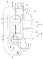
後席用空調ユニット50は、車両後方側の例えばトランクルーム内に配置されている。後席用空調ユニット50は、車室内に送風される空調空気の通路を形成する後席用ケーシング51を有している。後席用ケーシング51は、例えば樹脂材料によって構成することができる。
後席用ケーシング51の空気流れ最上流側には、空調空気を後席用ケーシング51の内部に導入するための吸入口52が設けられている。吸入口52には、図示しない連結ダクト(吸込みダクト)が接続されており、車室内空気(内気)を取り入れる。
後席用ケーシング51における吸入口52の空気流れ下流側には、吸入口52から吸入した空気を車室内へ向けて送風する後席用送風機53が配置されている。後席用送風機53は、例えば遠心多翼ファン(シロッコファン)であり、送風モータ54によって回転駆動される。送風モータ54は、空調制御装置80から出力される制御電圧によって回転数が制御される。
後席用ケーシング51における後席用送風機53の空気流れ下流側には、後席用蒸発器17が配置されている。後席用蒸発器17は、低温冷媒によって空調空気を冷却する。
後席用ケーシング51の空気流れ最下流部には、空調空気を車室内へ吹き出すための後席用開口部55、56が設けられている。後席用開口部55、56には、車室内左側から空調空気を吹き出すための第1開口部55、車室内右側から空調空気を吹き出すための第2開口部56が含まれている。これらの開口部55、56の空気流れ下流側は、それぞれ空気通路を形成するダクトを介して、車室内に設けられた図示しない吹出口に接続されている。
後席用開口部55、56の空気流れ上流側には、それぞれ、後席用空調ドア57、58が配置されている。後席用空調ドア57、58は、対応する後席用開口部55、56を開閉する。これらの後席用空調ドア57、58は、空調制御装置80から出力される制御信号によって作動が制御される図示しない電動アクチュエータによって駆動される。
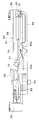
後席用ケーシング51では、後席用蒸発器17の空気流れ下流側であって、後席用空調ドア57、58の空気流れ上流側で機器冷却通路59が分岐している。機器冷却通路59は、後席用蒸発器17によって冷却された空調空気を電気機器70に供給するための空気通路である。機器冷却通路59の周囲は、断熱材で覆われている。
電気機器70は、作動に伴って発熱する機器であり、温調装置1の冷却対象機器である。電気機器70としては、車両用の各種制御装置(ECU)、2次電池、電動モータ、インバータ等を例示できる。本実施形態では、電気機器70として車両の自動運転制御を実施する制御装置である自動運転用ECUを用いている。
電気機器70は、車両後方側に配置されており、後席用空調ユニット50の近傍に配置されている。電気機器70は、機器冷却通路59と接するように配置されている。本実施形態では、2つの電気機器70が機器冷却通路59の上面に配置されている。
機器冷却通路59における電気機器70に対応する部位には、開口部59aが形成されている。開口部59aは、任意の形状とすることができ、1つの穴でもよく、複数のスリットでもよい。機器冷却通路59を流れる空調空気は、開口部59aを介して電気機器70に接触し、電気機器70を冷却する。
本実施形態の機器冷却通路59は、電気機器70を冷却した後の空調空気を後席用空調ユニット50に循環させる。機器冷却通路59は、空気流れ下流側端部が後席用ケーシング51における後席用送風機53の空気流れ上流側に接続している。電気機器70を冷却した後の空調空気は、後席用ケーシング51における後席用送風機53の空気流れ上流側に流入し、吸入口52から流入する空気と合流する。
機器冷却通路59には、通路開閉部60が設けられている。通路開閉部60は、後席用ケーシング51から機器冷却通路59に空調空気を流入させるか否かを切り替え、電気機器70に空調空気を供給するか否かを切り替える。
通路開閉部60には、機器冷却通路59を開閉する通路開閉ドア61が設けられている。通路開閉ドア61は、空調制御装置80から出力される制御信号によって作動が制御される図示しない電動アクチュエータによって駆動される。
電気機器70には、電気機器70の温度を検出する温度センサ71が設けられている。温度センサ71の検出信号は、空調制御装置80に入力される。
空調制御装置80は、CPU、ROMおよびRAM等を含む周知のマイクロコンピュータとその周辺回路から構成されている。そして、そのROM内に記憶された制御プログラムに基づいて各種演算、処理を行い、その出力側に接続された各種制御対象機器の作動を制御する。本実施形態の空調制御装置80は、電気機器70の冷却制御を行う。
次に、本実施形態の温調装置1による電気機器70の冷却制御を図4のフローチャートを用いて説明する。冷凍サイクル装置10は、予め作動しているものとする。
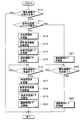
まず、S10で電気機器70の冷却が必要であるか否かを判定する。例えば、温度センサ71で検出した電気機器70の温度が所定温度を上回っている場合に、電気機器70の冷却が必要であると判断することができる。
S10の判定処理の結果、電気機器70の冷却が必要ではないと判定された場合には、電気機器70の冷却制御を終了する。一方、電気機器70の冷却が必要であると判定された場合には、S11で後席用空調ユニット50が作動中であるか否かを判定する。
この結果、後席用空調ユニット50が作動中ではないと判定された場合には、S12で冷媒開閉弁18を開放し、S13で後席用送風機53の作動を開始する。これにより、後席用空調ユニット50が作動を開始し、後席用蒸発器17で低温冷媒によって空調空気が冷却される。
後席用送風機53の送風量は、電気機器70の冷却に最低限必要とされる量であり、かつ、後席用送風機53の回転に伴う騒音が車室内の乗員に許容できる量とすればよい。例えば、後席用送風機53の送風量を5~10m3/h程度とすることが望ましい。
次に、S14で後席用空調ドア57、58を閉鎖し、S15で通路開閉ドア61を開放する。これにより、後席用蒸発器17で低温冷媒によって冷却された空調空気の全量が機器冷却通路59に流れ、電気機器70が空調空気によって冷却される。
次に、S16で電気機器70の冷却を終了するか否かを判定する。例えば、温度センサ71で検出した電気機器70の温度が所定温度を下回った場合に、電気機器70の冷却を終了すると判断することができる。S16の判定処理は、電気機器70の冷却を終了すると判定されるまで繰り返し行われる。つまり、電気機器70の温度が所定温度を下回るまで、空調空気による電気機器70の冷却が継続して行われる。
S16の判定処理の結果、電気機器70の冷却を終了すると判定された場合には、S17で冷媒開閉弁18を閉鎖し、S18で後席用送風機53の作動を停止する。これにより、後席用膨張弁15及び後席用蒸発器17に冷媒が流れなくなり、後席用送風機53による空調空気の送風が停止され、後席用空調ユニット50の作動が停止する。続いて、S19で後席用空調ドア57、58を開放し、S20で通路開閉ドア61を閉鎖する。これにより、機器冷却通路59への空調空気の流入が遮断され、電気機器70の冷却が終了する。
上述したS11の判定処理で、後席用空調ユニット50が作動中であると判定された場合には、S21で通路開閉ドア61を開放する。このとき、冷媒開閉弁18が開放しており、後席用送風機53が作動しており、後席用空調ドア57、58が開放しており、後席用空調ユニット50から車両後席側に空調空気が供給されている。
このため、通路開閉ドア61を開放することで、後席用蒸発器17で冷却された空調空気の一部が機器冷却通路59に流れる。これにより、電気機器70が空調空気によって冷却される。後席用送風機53の送風量は、車両後席側の空調に必要な送風量に依存する。
次に、S22で電気機器70の冷却を終了するか否かを判定する。S22の判定処理は、電気機器70の冷却を終了すると判定されるまで繰り返し行われる。つまり、電気機器70の温度が所定温度を下回るまで、空調空気による電気機器70の冷却が継続して行われる。
S22の判定処理の結果、電気機器70の冷却を終了すると判定された場合には、S23で通路開閉ドア61を閉鎖する。これにより、機器冷却通路59への空調空気の流入が遮断され、電気機器70の冷却が終了する。
以上説明した本実施形態では、後席用空調ユニット50の空調空気を利用して、車両後方側に配置された電気機器70を冷却している。これにより、電気機器70を適正温度に維持することができ、電気機器70の耐久性向上及び品質確保を図ることができる。
また、後席用空調ユニット50の空調空気で車両後方側に配置された電気機器70を冷却することで、後席用空調ユニット50の空調空気を電気機器70に供給する機器冷却通路59を極力短くすることができる。このため、温調装置1の車両への搭載性を向上させることができる。さらに、機器冷却通路59を短くすることができることから、後席用空調ユニット50から供給される空調空気の温度変化を極力小さくすることができ、熱ロスを低減することができる。
また、電気機器70の冷却を行う後席用空調ユニット50は、車室内の空調に補助的に用いられる。このため、後席用空調ユニット50の冷却能力の一部を電気機器70の冷却に用いても、車室内の空調に与える影響を極力小さくすることができる。
また、本実施形態では、後席用ケーシング51における後席用蒸発器17の空気流れ下流側で、機器冷却通路59を分岐させている。このため、後席用蒸発器17で低温冷媒によって冷却された空調空気を電気機器70に供給することができ、電気機器70を効率よく冷却することができる。
また、本実施形態では、機器冷却通路59に通路開閉部60を設け、電気機器70の冷却が必要な場合に、機器冷却通路59に空調空気を流入させている。このため、電気機器70の冷却が不要な場合には、機器冷却通路59に空調空気が流入せず、車室内の空調に与える影響を極力小さくすることができる。
また、本実施形態では、機器冷却通路59の空気流れ下流側端部が後席用ケーシング51に接続しており、電気機器70を冷却した後の空調空気が後席用空調ユニット50に循環させるようになっている。これにより、電気機器70を冷却した後の空調空気が車両後方側(例えばトランクルーム内)に吹き出すことを防止できる。
(第2実施形態)
次に、本開示の第2実施形態について説明する。上記第1実施形態と同様の部分は説明を省略し、異なる部分についてのみ説明する。
次に、本開示の第2実施形態について説明する。上記第1実施形態と同様の部分は説明を省略し、異なる部分についてのみ説明する。
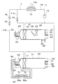
図5に示すように、本第2実施形態では、後席用ケーシング51における後席用送風機53の空気流れ下流側かつ後席用蒸発器17の空気流れ上流側で機器冷却通路59が分岐している。このため、本第2実施形態では、電気機器70に後席用蒸発器17で冷却される前の空調空気が供給される。つまり、電気機器70に単なる送風が行われる。
また、本第2実施形態では、通路開閉部60が設けられていない。このため、後席用送風機53が作動していれば、電気機器70には後席用空調ユニット50から常に空調空気が供給される。電気機器70への送風量は5m3/h程度以下であれば、後席用空調ユニット50による車室内の空調に与える影響が小さい。
以上説明した本第2実施形態によれば、電気機器70がそれほど高温にならない場合であれば、後席用蒸発器17を通過する前の空調空気によって、電気機器70を充分に冷却することができる。
また、本第2実施形態では、電気機器70を冷却するために後席用送風機53を作動させるだけでよく、後席用空調ユニット50による車室内の空調を行っていない場合には、電気機器70の冷却時に後席用蒸発器17に冷媒を供給する必要がない。
また、本第2実施形態では、通路開閉部60が設けられていない。このため、空調制御装置80による通路開閉部60の開閉制御を行う必要がなく、温調装置1の構成を簡素化することができる。
本開示は上述の実施形態に限定されることなく、本開示の趣旨を逸脱しない範囲内で、以下のように種々変形可能である。また、上記各実施形態に開示された手段は、実施可能な範囲で適宜組み合わせてもよい。
例えば、上記実施形態では、電気機器70を冷却した後の空調空気を後席用空調ユニット50に循環させるようにしたが、電気機器70を冷却した後の空調空気を後席用空調ユニット50に循環させないようにしてもよい。
また、上記実施形態では、電気機器70が2個設けられた例について説明したが、電気機器70は1個でも3個以上でもよい。
本開示は、実施例に準拠して記述されたが、本開示は当該実施例や構造に限定されるものではないと理解される。本開示は、様々な変形例や均等範囲内の変形をも包含する。加えて、様々な組み合わせや形態、さらには、それらに一要素のみ、それ以上、あるいはそれ以下、を含む他の組み合わせや形態をも、本開示の範疇や思想範囲に入るものである。
Claims (6)
- 車両前方側に配置され、主に車両前席側に空調空気を送風する前席用空調ユニット(20)と、
車両後方側に配置され、主に車両後席側に空調空気を送風する後席用空調ユニット(50)と、
車両後方側に配置され、作動に伴って発熱する電気機器(70)と、
前記後席用空調ユニットで冷却された空調空気を前記電気機器に供給するための機器冷却通路(59)と、
を備える温調装置。 - 前記後席用空調ユニットには、冷凍サイクル装置(10)の蒸発器(17)が設けられており、
前記後席用空調ユニットにおける前記蒸発器の空気流れ下流側に、前記機器冷却通路が分岐して設けられている請求項1に記載の温調装置。 - 前記機器冷却通路には、前記機器冷却通路を開閉し、前記電気機器に空調空気を供給するか否かを切り替える通路開閉部(60)が設けられている請求項1または2に記載の温調装置。
- 前記後席用空調ユニットには、冷凍サイクル装置(10)の蒸発器(17)が設けられており、
前記後席用空調ユニットにおける前記蒸発器の空気流れ上流側に、前記機器冷却通路が分岐して設けられている請求項1に記載の温調装置。 - 前記機器冷却通路は、前記電気機器を冷却した後の空調空気を前記後席用空調ユニットに循環させる請求項1ないし4のいずれか1つに記載の温調装置。
- 前記電気機器は、前記車両の自動運転制御を実施する制御装置である請求項1ないし5のいずれか1つに記載の温調装置。
Applications Claiming Priority (2)
| Application Number | Priority Date | Filing Date | Title |
|---|---|---|---|
| JP2019-024257 | 2019-02-14 | ||
| JP2019024257A JP2020131778A (ja) | 2019-02-14 | 2019-02-14 | 温調装置 |
Publications (1)
| Publication Number | Publication Date |
|---|---|
| WO2020166271A1 true WO2020166271A1 (ja) | 2020-08-20 |
Family
ID=72045299
Family Applications (1)
| Application Number | Title | Priority Date | Filing Date |
|---|---|---|---|
| PCT/JP2020/001337 WO2020166271A1 (ja) | 2019-02-14 | 2020-01-16 | 温調装置 |
Country Status (2)
| Country | Link |
|---|---|
| JP (1) | JP2020131778A (ja) |
| WO (1) | WO2020166271A1 (ja) |
Families Citing this family (1)
| Publication number | Priority date | Publication date | Assignee | Title |
|---|---|---|---|---|
| JP2022061404A (ja) * | 2020-10-06 | 2022-04-18 | トヨタ自動車株式会社 | 車両用電子機器の冷却装置、車両用電子機器の冷却装置の制御方法及び車両用電子機器の冷却装置の制御プログラム |
Citations (3)
| Publication number | Priority date | Publication date | Assignee | Title |
|---|---|---|---|---|
| JPH05178070A (ja) * | 1991-12-27 | 1993-07-20 | Nippondenso Co Ltd | 電気自動車用空調装置 |
| JP2007137127A (ja) * | 2005-11-15 | 2007-06-07 | Denso Corp | 車両用電池冷却・空調装置 |
| JP2014204576A (ja) * | 2013-04-05 | 2014-10-27 | トヨタ自動車株式会社 | 車両駆動用電気機器の冷却システム |
-
2019
- 2019-02-14 JP JP2019024257A patent/JP2020131778A/ja active Pending
-
2020
- 2020-01-16 WO PCT/JP2020/001337 patent/WO2020166271A1/ja active Application Filing
Patent Citations (3)
| Publication number | Priority date | Publication date | Assignee | Title |
|---|---|---|---|---|
| JPH05178070A (ja) * | 1991-12-27 | 1993-07-20 | Nippondenso Co Ltd | 電気自動車用空調装置 |
| JP2007137127A (ja) * | 2005-11-15 | 2007-06-07 | Denso Corp | 車両用電池冷却・空調装置 |
| JP2014204576A (ja) * | 2013-04-05 | 2014-10-27 | トヨタ自動車株式会社 | 車両駆動用電気機器の冷却システム |
Also Published As
| Publication number | Publication date |
|---|---|
| JP2020131778A (ja) | 2020-08-31 |
Similar Documents
| Publication | Publication Date | Title |
|---|---|---|
| US7152417B2 (en) | Battery cooling apparatus with sufficient cooling capacity | |
| CN107709067B (zh) | 车用空调装置 | |
| JP6278214B2 (ja) | 車両用空調装置 | |
| JP5609764B2 (ja) | 車両用空調装置 | |
| JP2003326962A (ja) | 車両用空調装置 | |
| JP2008296717A (ja) | 車両用空調装置 | |
| WO2016186170A1 (ja) | 車両用空調装置 | |
| JP6658600B2 (ja) | 車両用空調装置 | |
| JP2007308133A (ja) | 車両用空調装置 | |
| JP2004155391A (ja) | 車両用空調装置 | |
| WO2018221137A1 (ja) | 車両用空調装置 | |
| JP2006298016A (ja) | 車両用空調装置 | |
| WO2020166271A1 (ja) | 温調装置 | |
| JP2009166629A (ja) | 車両用空調装置 | |
| JP5012758B2 (ja) | 車両用空調装置 | |
| JP2007283829A (ja) | 車両用空調装置 | |
| JP5494595B2 (ja) | 車両用空調装置 | |
| WO2015068363A1 (ja) | 車両用空調装置 | |
| WO2017014030A1 (ja) | 車両用空調装置 | |
| JP6372110B2 (ja) | 車両用空調装置 | |
| WO2019138807A1 (ja) | 車両用空調装置及び車両用空調装置の制御方法 | |
| JPH0717150B2 (ja) | 車両用の空気調和装置 | |
| JP2019085095A (ja) | 流体加熱装置 | |
| JP3993524B2 (ja) | 車両用空調装置 | |
| JP2007245989A (ja) | 車両用空調装置 |
Legal Events
| Date | Code | Title | Description |
|---|---|---|---|
| 121 | Ep: the epo has been informed by wipo that ep was designated in this application |
Ref document number: 20755025 Country of ref document: EP Kind code of ref document: A1 |
|
| NENP | Non-entry into the national phase |
Ref country code: DE |
|
| 122 | Ep: pct application non-entry in european phase |
Ref document number: 20755025 Country of ref document: EP Kind code of ref document: A1 |