WO2020166217A1 - 金銭処理装置用表示システム - Google Patents
金銭処理装置用表示システム Download PDFInfo
- Publication number
- WO2020166217A1 WO2020166217A1 PCT/JP2019/050669 JP2019050669W WO2020166217A1 WO 2020166217 A1 WO2020166217 A1 WO 2020166217A1 JP 2019050669 W JP2019050669 W JP 2019050669W WO 2020166217 A1 WO2020166217 A1 WO 2020166217A1
- Authority
- WO
- WIPO (PCT)
- Prior art keywords
- error
- image data
- money processing
- procedure
- display
- Prior art date
- Legal status (The legal status is an assumption and is not a legal conclusion. Google has not performed a legal analysis and makes no representation as to the accuracy of the status listed.)
- Ceased
Links
Images










Classifications
-
- G—PHYSICS
- G07—CHECKING-DEVICES
- G07D—HANDLING OF COINS OR VALUABLE PAPERS, e.g. TESTING, SORTING BY DENOMINATIONS, COUNTING, DISPENSING, CHANGING OR DEPOSITING
- G07D11/00—Devices accepting coins; Devices accepting, dispensing, sorting or counting valuable papers
- G07D11/20—Controlling or monitoring the operation of devices; Data handling
- G07D11/26—Servicing, repairing or coping with irregularities, e.g. power failure or vandalism
-
- G—PHYSICS
- G07—CHECKING-DEVICES
- G07D—HANDLING OF COINS OR VALUABLE PAPERS, e.g. TESTING, SORTING BY DENOMINATIONS, COUNTING, DISPENSING, CHANGING OR DEPOSITING
- G07D11/00—Devices accepting coins; Devices accepting, dispensing, sorting or counting valuable papers
- G07D11/60—User-interface arrangements
-
- G—PHYSICS
- G07—CHECKING-DEVICES
- G07D—HANDLING OF COINS OR VALUABLE PAPERS, e.g. TESTING, SORTING BY DENOMINATIONS, COUNTING, DISPENSING, CHANGING OR DEPOSITING
- G07D9/00—Counting coins; Handling of coins not provided for in the other groups of this subclass
-
- G—PHYSICS
- G07—CHECKING-DEVICES
- G07G—REGISTERING THE RECEIPT OF CASH, VALUABLES, OR TOKENS
- G07G1/00—Cash registers
Definitions
- the present invention relates to a display system for a money processing device, and more specifically, for example, money for releasing an error in a money processing device connected to a POS (Point Of Sales) register device of a store such as a supermarket and returning to a normal state.
- the present invention relates to a display system for a processing device.
- money processing devices such as automatic change dispensers connected to POS terminals have been known in stores such as supermarkets and convenience stores.
- Such a money processing device normally deposits banknotes and coins deposited by a shopper and stores them in a storage box, while withdrawing change from the storage box according to a withdrawal instruction.
- the error canceling operation is to remove the jammed coin.
- the jam of coins is considered to be caused by the contamination of the transport path for transporting coins, and unless the transport path is cleaned, a coin jam error occurs repeatedly.
- the above-described display system for a money processing device is useful for improving the operability and convenience of error cancellation when an error occurs in the money processing device, but the error cancellation operation when the error occurs However, it was not possible to reduce the occurrence of future errors.
- the present invention provides a display system for a money processing apparatus capable of reducing the occurrence of future errors as necessary while improving the operability and convenience of error cancellation. To aim.
- a display system for a money processing device is a display unit electrically connected to a money processing device for processing deposits and withdrawals of money, and displaying predetermined information, and the money.
- An error canceling operation for canceling an error occurring in the processing device and returning to a normal state is an error canceling operation including a plurality of image data for the error canceling operation prepared according to each stage of the progress of the error canceling operation.
- a display system for a money processing apparatus comprising: a control unit for sequentially displaying image data for use on the display unit at each stage of the progress of the error release operation, wherein the storage unit is different from the error release operation.
- the maintenance operation for removing the cause of the occurrence of the error has maintenance procedure data including a plurality of image data for the maintenance operation prepared according to each stage of the progress of the maintenance operation, and the control means is An input unit for displaying the image data for maintenance operation is displayed on the display unit when the image data for error clearing operation is sequentially displayed on the display unit, and an input operation is performed through the input unit.
- the maintenance procedure data related to the error causing the image data for the error canceling operation to be displayed is read from the storage means, and the image data for the maintenance operation is displayed on the display means. Characterize.
- the image data for the error releasing operation is a situation of the money processing apparatus seen by an operator at each stage of the progress of the error releasing operation.
- a plurality of image data for maintenance operation is prepared according to each stage of the progress of the error releasing operation, and the image data for the maintenance operation is the situation of the money processing apparatus that the operator sees at each stage of the progress of the maintenance operation. Therefore, it is characterized in that a plurality is prepared according to each stage of the progress of the maintenance operation.
- the control unit detects, through the detection unit, that a new error has occurred while displaying the image data for maintenance operation on the display unit.
- the new error is treated as an in-operation error, and is distinguished from the error that causes the image data for the error canceling operation to be displayed.
- the control unit when the control unit records the operating error together with an error that causes the image data for the error canceling operation to be displayed as history information, the operation is performed.
- the medium error is characterized by being marked with a predetermined mark and recorded.
- the present invention is also characterized in that, in the display system for a money processing device, the control means distinguishes the in-operation error by not recording it in history information.
- the control means is a new device detected by the detection means after the input operation is performed through the input unit until the money processing device returns to the normal state. It is characterized in that the error is an error during the operation.
- the control means when the control means detects through the detection means that an error has occurred in the money processing apparatus, the error release operation procedure data corresponding to the error is read from the storage means, and the error release operation procedure data is read out. Since the image data is sequentially displayed on the display means at each stage of the progress of the error canceling operation, it is not necessary to prepare an instruction manual, etc., and the operator can perform the error canceling operation according to the display of the displaying means. .. Moreover, when the control means sequentially displays the image data for the error clearing operation on the display means, the control means displays the input section for displaying the image data for the maintenance operation on the display means, and the input operation is performed through the input section.
- the maintenance procedure data related to the error that caused the image data for the error canceling operation to be displayed is read from the storage means, and the image data for the maintenance operation is displayed on the display means.
- the operator can perform maintenance operations. Therefore, it is possible to reduce the occurrence of future errors as necessary while improving the operability and convenience of error cancellation.
- FIG. 1 is a block diagram schematically showing the configuration of a money processing device display system according to an embodiment of the present invention.
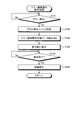
- FIG. 2 is a flowchart showing the processing contents of the error cancellation operation display processing executed by the control unit shown in FIG.
- FIG. 3 is an image diagram showing the procedure of the error releasing operation.
- FIG. 4 is an image diagram showing the procedure of the error releasing operation.
- FIG. 5 is an image diagram showing the procedure of the error releasing operation.
- FIG. 6 is an image diagram showing the procedure of the error releasing operation.
- FIG. 7 is an image diagram showing the procedure of the error releasing operation.
- FIG. 8 is an image diagram showing the procedure of the error releasing operation.
- FIG. 9 is an image diagram showing the procedure of the error releasing operation.
- FIG. 1 is a block diagram schematically showing the configuration of a money processing device display system according to an embodiment of the present invention.
- FIG. 2 is a flowchart showing the processing contents of the error cancellation operation display processing executed by the control unit shown
- FIG. 10 is an image diagram showing the procedure of the error releasing operation.
- FIG. 11 is an image diagram showing the procedure of the error releasing operation.
- FIG. 12 is an image diagram showing the procedure of the maintenance operation.
- FIG. 13 is an image diagram showing the procedure of the maintenance operation.
- FIG. 14 is an image diagram showing the procedure of the error releasing operation.
- FIG. 15 is an image diagram showing the procedure of the error releasing operation.
- FIG. 16 is an image diagram showing the procedure of the error releasing operation.
- FIG. 17 is an image diagram showing the procedure of the error releasing operation.
- FIG. 18 is an image diagram showing the procedure of the error releasing operation.
- FIG. 19 is an image diagram showing the procedure of the error releasing operation.
- FIG. 1 is a block diagram schematically showing a configuration of a display system for a money processing device according to an embodiment of the present invention.
- the display system for a money processing device illustrated here is configured by a POS register device 10 as a terminal device that collects and manages information when a commercial transaction with a customer is performed in a store such as a supermarket or a convenience store.
- An automatic change dispenser 20 as a money processing device is electrically connected to the POS register device 10.
- the automatic change dispenser 20 is configured to include a coin unit 21, a bill unit 22, an operation input unit 23, and a money control unit 24.
- the coin unit 21 deposits and withdraws coins, and has various sensor groups 21a and actuator groups 21b.
- the coin unit 21 supplies coins inserted through a coin slot (not shown) in a state of being separated one by one, discriminates the authenticity and denomination of the coins, and sorts the coins (genuine coins) after they are conveyed. It is to be stored according to the type of money.
- the coin unit 21 is for paying out coins to be stored to a coin outlet (not shown) in response to a withdrawal command.
- the sensor group 21a forming the coin portion 21 includes a sensor as a detection unit that detects that an error has occurred in the coin portion 21.
- the bill unit 22 deposits and withdraws bills, and has various sensor groups 22a and actuator groups 22b.
- the bill unit 22 conveys bills inserted into a bill insertion slot (not shown), discriminates between genuineness and denomination of the bills in the middle of the conveyance, and denominates bills determined to be genuine coins. It is to be sorted and stored accordingly. Note that the banknotes that are determined not to be genuine coins are conveyed to a banknote dispensing port (not shown).
- the banknote unit 22 pays out the banknotes to be stored and withdraws it from the banknote withdrawal port when a withdrawal instruction is given.
- the sensor group 22a that configures the banknote unit 22 includes a sensor as a detection unit that detects that an error has occurred in the banknote unit 22.
- the operation input unit 23 is composed of, for example, a numeric keypad, various buttons, and the like, and is a part for performing an input operation.
- the money control unit 24 centrally controls the operation of the automatic change dispenser 20 in accordance with programs and data stored in advance.
- the POS register device 10 is a higher-level device of the automatic change dispenser 20. By reading a bar code with a bar code reader (scanner) not shown, data such as a product name, a price, and customer information is immediately input. It is configured by a computer-based register, and is configured by including a display unit 11 and a control unit 12.
- the display unit 11 is a display unit composed of, for example, a liquid crystal touch panel, and is capable of displaying various information and performing an input operation such as a touch operation.
- the control unit 12 is a control unit that comprehensively controls the operation of the POS register device 10 in accordance with the programs and data stored in the storage unit 13.
- the control unit 12 may be realized by, for example, causing a processing device such as a CPU (Central Processing Unit) to execute a program, that is, by software, or by hardware such as an IC (Integrated Circuit). It may be realized by using both software and hardware.
- a processing device such as a CPU (Central Processing Unit) to execute a program, that is, by software, or by hardware such as an IC (Integrated Circuit). It may be realized by using both software and hardware.
- IC Integrated Circuit
- error release operation procedure data 13a and maintenance procedure data 13b are stored.
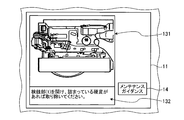
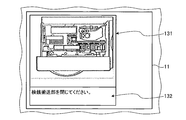
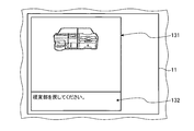
- the error canceling operation procedure data 13a is provided for each component of the coin section 21 and the banknote section 22 of the automatic change dispenser 20, and when an error occurs in the corresponding constituent element, the error is canceled. It has image data 131 (see FIG. 3 and the like) showing an error canceling operation for returning to a normal state for each procedure and word data 132 (see FIG. 3 and the like) for each procedure.
- the maintenance procedure data 13b is provided for each component of the coin section 21 and the banknote section 22 of the automatic change dispenser 20, and the image data 141 indicating the maintenance operation of the corresponding component for each procedure (see FIG. 12). ) And the wording data 142 (see FIG. 12) for each procedure.
- Such maintenance operations include cleaning operations such as removing the stains on the relevant parts, replacement operations for exchanging the relevant parts, etc., and when an error occurs, it is necessary to restore the error state to a normal state. This is different from the error clearing operation.
- FIG. 2 is a flowchart showing the processing contents of the error cancellation operation display processing executed by the control unit 12 shown in FIG.
- the control unit 12 determines whether or not any one of the sensor groups 21a and 22a of the coin unit 21 and the bill unit 22 has detected an error (step S101). More specifically, the control unit 12 determines whether or not a signal indicating that an error has occurred is given from the money control unit 24 of the automatic change dispenser 20. When it is determined that a signal indicating that an error has occurred is given from the money control unit 24, that is, it is determined that one of the sensors 21a and 22a of the coin unit 21 and the bill unit 22 has detected an error. If so (step S101: Yes), the control unit 12 identifies the error occurrence unit (step S102).
- the control unit 12 that has identified the error occurrence unit in this way reads the error cancellation operation procedure data 13a of the constituent element that is the error occurrence unit from the storage unit 13 (step S103), and sequentially displays it on the display unit 11 (step S104). ).
- step S104 The process of step S104 will be specifically described. In addition, here, it is assumed that the coin inspection unit in the coin unit 21 that discriminates the authenticity of coins and the denomination is an error occurrence unit.
- the control unit 12 has the image data 131 of the automatic change machine 20 which is the first error releasing procedure and the word data 132 of “Please pull out the coin portion” corresponding to the error releasing procedure. Is displayed on the display unit 11. After a lapse of a predetermined time (for example, 2 seconds to 5 seconds) after displaying the first error canceling procedure, the control unit 12 causes the automatic change machine 20 to perform the second error canceling procedure, as shown in FIG. The image data 131 and the word data 132 of “Please pull out the coin part” corresponding to the error cancellation procedure are displayed on the display unit 11.
- a predetermined time for example, 2 seconds to 5 seconds
- the control unit 12 After a lapse of a predetermined time from displaying the second error canceling procedure, the control unit 12, as shown in FIG. 5, the image data 131 of the automatic change dispenser 20 to be the third error canceling procedure and the error canceling.
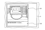
- the wording data 132 of “Please open the operation display section” corresponding to the procedure is displayed on the display section 11.
- the control unit 12 controls the image data 131 of the automatic change dispenser 20 to be the fourth error releasing procedure and the error as shown in FIG.
- the wording data 132 of “Please open the operation display section” corresponding to the release procedure is displayed on the display section 11.
- the control unit 12 After a lapse of a predetermined time from displaying the fourth error canceling procedure, the control unit 12, as shown in FIG. 7, the image data 131 of the automatic change dispenser 20 to be the fifth error canceling procedure, and the error canceling.
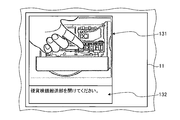
- the wording data 132 of “Please open the coin inspection transport section.” corresponding to the procedure is displayed on the display section 11.
- the control unit 12 After a lapse of a predetermined time from displaying the fifth error canceling procedure, the control unit 12, as shown in FIG. 8, the image data 131 of the automatic change dispenser 20 to be the sixth error canceling procedure and the error.
- the display unit 11 displays the word data 132 of “Please open the coin inspection transport unit.” corresponding to the release procedure.
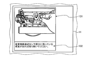
- the control unit 12 After a lapse of a predetermined time from displaying the sixth error release procedure, the control unit 12 causes the image data 131 of the automatic change dispenser 20 to be the seventh error release procedure and the error release as shown in FIG.
- the display unit 11 displays the wording data 132 of “Please remove any coins remaining in the coin inspection passage sensor part.” corresponding to the procedure.
- the control unit 12 controls the image data 131 of the automatic change dispenser 20 to be the eighth error canceling procedure and the error, as shown in FIG.
- the display unit 11 displays the wording data 132 of “Open the coin inspection unit (1) and remove any stuck coins” corresponding to the release procedure.
- the control unit 12 After a lapse of a predetermined time from displaying the eighth error canceling procedure, the control unit 12, as shown in FIG. 11, the image data 131 of the automatic change dispenser 20, which is the ninth error canceling procedure, and the error canceling.
- the display section 11 displays the wording data 132 of “Open the coin inspection section (1) and remove any stuck coins” corresponding to the procedure.
- the input unit 14 for displaying the image data 131 and the wording data 132 and the image data 141 for maintenance operation is displayed on the display unit 11.
- the control unit 12 When the input operation is performed through the input unit 14, the control unit 12 reads out the maintenance procedure data 13b related to the error that causes the image data 131 for the error release operation to be displayed from the storage unit 13. Then, as shown in FIG. 12, the control unit 12 controls the image data 141 of the automatic change machine 20 which is the first maintenance procedure, and "cleans the hand stains on a waste cloth with anhydrous alcohol so as to wipe it off.
- the wording data 142 of “Please.” is displayed on the display unit 11. Further, the control unit 12 displays, together with the image data 141 and the wording data 142, the cancel input unit 15 for closing the maintenance operation image data 141 and the like and transitioning to the error cancellation operation image data 131 and the like. It is displayed on the section 11.
- the control section 12 controls the automatic change machine 20 to be the second maintenance procedure as shown in FIG. Image data 141 and the wording data 142 corresponding to the error canceling procedure, "Turn the belt by hand to rotate the pulley around and remove black residue on the groove with tweezers."
- the cancel input unit 15 is displayed on the display unit 11 as well as the display unit 11.
- the control unit 12 Since the maintenance procedure data 13b is completed in the second maintenance procedure, the control unit 12 displays the image data 141 and the wording data 142 of the first maintenance procedure again after a predetermined time has elapsed, and the maintenance procedure data 13b is displayed. The display is repeated and the input of the cancel input unit 15 is awaited.
- the control unit 12 causes the display unit 11 to display the ninth error cancellation procedure shown in FIG.
- the control unit 12 displays the tenth error as shown in FIG.
- the image data 131 of the automatic change machine 20 which is the error canceling procedure and the wording data 132 of “Please close the money inspection section (1).” corresponding to the error canceling procedure are displayed on the display section 11.
- the control unit 12 After a lapse of a predetermined time from displaying the tenth error canceling procedure, the control unit 12, as shown in FIG. 15, the image data 131 of the automatic change dispenser 20 to be the eleventh error canceling procedure and the error canceling.
- the display unit 11 displays the wording data 132 of “Please close the coin inspection transport unit.” corresponding to the procedure.
- the control unit 12, as shown in FIG. 16 displays the image data 131 of the automatic change dispenser 20 to be the twelfth error canceling procedure and the error.
- the wording data 132 of “Please close the operation display section” corresponding to the release procedure is displayed on the display section 11.
- the control unit 12 After a lapse of a predetermined time from displaying the twelfth error canceling procedure, the control unit 12, as shown in FIG. 17, the image data 131 of the automatic change dispenser 20 to be the thirteenth error canceling procedure and the error canceling.
- the wording data 132 of “Please return the coin part” corresponding to the procedure is displayed on the display unit 11.
- the control unit 12 After a lapse of a predetermined time from displaying the thirteenth error canceling procedure, the control unit 12, as shown in FIG. 18, the image data 131 of the automatic change dispenser 20 to be the fourteenth error canceling procedure and the error.
- the display unit 11 displays the wording data 132 of “Please return the coin part” corresponding to the release procedure.
- step S104 After a lapse of a predetermined time from displaying the fourteenth error canceling procedure, the control unit 12, as shown in FIG. 19, the image data 131 of the automatic change dispenser 20, which is the fifteenth error canceling procedure, and the error canceling.
- the processing of step S104 is performed by displaying the wording data 132 of "Please press the cancel/restore button.” corresponding to the procedure on the display unit 11.
- control unit 12 determines whether or not the display has ended by determining whether or not the cancel/recovery button forming the operation input unit 23 has been pressed (step S105). ).
- step S105 Yes
- the control unit 12 displays the standby state on the display unit 11 as returning to the normal state (step S106), and then returns the error cancellation procedure. This processing ends.
- the control unit 12 when the control unit 12 detects that an error has occurred in the automatic change dispenser 20 through the sensor groups 21a and 22a, The error release operation procedure data 13a corresponding to the error is read from the storage unit 13, and the image data 131 for the error release operation is sequentially displayed on the display unit 11 at each stage of the progress of the error release operation. It is possible to allow the operator to perform the error canceling operation according to the display on the display unit 11 without having to prepare. Moreover, the control unit 12 causes the display unit 11 to display the input unit 14 for displaying the maintenance operation image data 141 when sequentially displaying the image data 131 for error canceling operation on the display unit 11.
- the maintenance procedure data 13b related to the error that causes the image data 131 for the error releasing operation to be displayed is read from the storage unit 13, and the image data 141 for the maintenance operation is displayed on the display unit. Since it is displayed on 11, the operator can perform the maintenance operation according to the display on the display unit 11. Therefore, it is possible to reduce the occurrence of future errors as necessary while improving the operability and convenience of error cancellation.
- any one of the sensors 21a, 22a of the coin unit 21 and the banknote unit 22 can be operated. It may detect the occurrence of new errors.
- the control unit 12 regards the new error as an in-operation error and causes the image data 131 for the error cancellation operation to be displayed (the error cancellation operation display). It is an error detected in step S101 in the processing, and it is preferable to distinguish it from the actual error). By thus distinguishing the actual error from the in-operation error, the number of errors caused by the operation of the automatic change dispenser 20 can be accurately recognized.
- the distinction between real error and in-operation error can be done as follows. That is, when the control unit 12 records both the actual error and the in-operation error as the history information, the in-operation error can be distinguished by recording with a predetermined mark. In addition, the control unit 12 can distinguish the in-operation error from the actual error by not recording the in-operation error in the history information.
- the control unit 12 uses the sensor groups 21a and 22a of the coin unit 21 and the bill unit 22 until the automatic change machine 20 returns to the normal state after the input operation is performed through the input unit 14. It is preferable that the new error detected be an in-operation error.
- the cancel/recovery button that constitutes the operation input unit 23 may be pressed as described above, or in addition to that, the power is turned on.
- the money processing device display system is configured by the POS register device 10.
- the display unit configuring the money processing device display system is, for example, a tablet carried by an operator. It may be a portable information terminal such as.
- the error canceling operation display process when the cancel input unit 15 is operated, the error canceling operation for the error canceling operation of the ninth error canceling procedure before displaying the image data 141 for the maintenance operation is performed.
- the image data 131 is displayed
- the transition destination of the image after the image data 141 for maintenance operation is displayed is not particularly limited in the present invention. Therefore, after the maintenance procedure data 13b (image data 141 for maintenance operation) is displayed, a standby display may be displayed assuming that the normal state has been restored.
- the tenth error release procedure The image data 131 or the like for the error canceling operation may be displayed.
- the input unit 14 for displaying the image data 141 for maintenance operation is displayed in the ninth error releasing procedure, but in the present invention, the image data for maintenance operation is displayed.
- the input unit for this may be added to the image data for the error releasing operation in an arbitrary error releasing procedure, and is not particularly limited.
- the money processing device may have a function of generating an error in a simulated manner for the purpose of training an operator.
- an error is generated in a simulated manner as described above, it is preferable to distinguish the simulated error from the actual error as well as the in-operation error.
- 10 POS register device, 11... Display unit, 12... Control unit, 13... Storage unit, 13a... Error canceling operation procedure data, 13b... Maintenance procedure data, 131... Image data for error canceling operation, 132... Error canceling operation Wording data for, 14... input section, 141... image data for maintenance operation, 142... wording data for maintenance operation, 15... cancel input section, 20... automatic change machine, 21... coin section, 21a... sensor group , 21b... Actuator group, 22... Banknote section, 22a... Sensor group, 22b... Actuator group, 23... Operation input section, 24... Money control section.
Landscapes
- Physics & Mathematics (AREA)
- General Physics & Mathematics (AREA)
- Cash Registers Or Receiving Machines (AREA)
Abstract
金銭の入出金を処理する自動釣銭機20でエラーが生じた場合、エラーに対応するエラー解除操作手順データ13aを記憶部13から読み出してエラー解除操作用の画像データ131をエラー解除操作の進捗の各段階毎に表示部11に順次表示させる制御部12を備え、この制御部12は、エラー解除操作用の画像データ131を表示部11に順次表示させる際にメンテナンス操作用の画像データ141を表示させるための入力部14を表示部11に表示させ、入力部14を通じて入力操作された場合に、エラー解除操作用の画像データ131を表示させる原因となったエラーに関連するメンテナンス手順データ13bを記憶部13から読み出すとともに、メンテナンス操作用の画像データ141を表示部11に表示させる。
Description
本発明は、金銭処理装置用表示システムに関し、より詳細には、例えばスーパーマーケット等の店舗のPOS(Point Of Sales)レジスタ装置に接続される金銭処理装置のエラーを解除して正常状態に復帰させる金銭処理装置用表示システムに関するものである。
従来、例えばスーパーマーケットやコンビニエンスストア等の店舗において、POS端末に接続された自動釣銭機等の金銭処理装置が知られている。このような金銭処理装置は通常、買い物客から預かった紙幣や硬貨を入金して収納庫に収納する一方で、出金指示により収納庫から釣銭を出金する。
そのような金銭処理装置にエラーが発生した場合、POSレジスタ装置の表示部に、該金銭処理装置で発生したエラーを解除して正常状態へ復帰するためのエラー解除操作を画像データとしてエラー解除操作の進捗状況に応じて順次表示させる金銭処理装置用表示システムが提案されている(例えば、特許文献1参照)。
ところで、金銭処理装置でのエラーの発生には原因があり、その原因を取り除かないと、エラーが再発する虞れがある。このエラーの発生原因には、機器の故障もあるが、繰り返し使用される構成要素の消耗や汚れ、異物の混入等もある。具体的に説明すると、金銭処理装置において硬貨詰まりというエラーが発生した場合、詰まった硬貨を取り除くのがエラー解除操作である。しかしながら、硬貨詰まりには、硬貨を搬送する搬送路の汚れ等が発生原因として考えられ、搬送路を清掃しない限り、硬貨詰まりのエラーが繰り返し発生することになる。
上述した金銭処理装置用表示システムは、金銭処理装置でエラーが発生した場合に、エラー解除の操作性及び利便性を向上させる有用なものであったが、あくまでエラーが発生したときのエラー解除操作の提示であり、将来的なエラーの発生を低減できるものではなかった。
本発明は、上記実情に鑑みて、エラー解除の操作性及び利便性を向上させつつ、将来的なエラーの発生を必要に応じて低減させることができる金銭処理装置用表示システムを提供することを目的とする。
上記目的を達成するために、本発明に係る金銭処理装置用表示システムは、金銭の入出金を処理する金銭処理装置に電気的に接続され、かつ所定の情報を表示する表示手段と、前記金銭処理装置で生じたエラーを解除して正常状態へ復帰するためのエラー解除操作が、該エラー解除操作の進捗の各段階に応じて複数用意されたエラー解除操作用の画像データを含むエラー解除操作手順データを格納する記憶手段と、前記金銭処理装置でエラーが生じたことが検出手段を通じて検出された場合、該エラーに対応するエラー解除操作手順データを前記記憶手段から読み出すとともに、前記エラー解除操作用の画像データをエラー解除操作の進捗の各段階毎に前記表示手段に順次表示させる制御手段とを備えた金銭処理装置用表示システムであって、前記記憶手段は、前記エラー解除操作とは異なってエラーの発生の原因を取り除くためのメンテナンス操作が、該メンテナンス操作の進捗の各段階に応じて複数用意されたメンテナンス操作用の画像データを含むメンテナンス手順データを有し、前記制御手段は、前記エラー解除操作用の画像データを前記表示手段に順次表示させる際に、前記メンテナンス操作用の画像データを表示させるための入力部を前記表示手段に表示させるものであり、前記入力部を通じて入力操作された場合に、該エラー解除操作用の画像データを表示させる原因となったエラーに関連するメンテナンス手順データを前記記憶手段から読み出すとともに、前記メンテナンス操作用の画像データを前記表示手段に表示させることを特徴とする。
また本発明は、上記金銭処理装置用表示システムにおいて、前記エラー解除操作用の画像データは、エラー解除操作の進捗の各段階で操作者が目にする前記金銭処理装置の状況のものであって、エラー解除操作の進捗の各段階に応じて複数用意されており、前記メンテナンス操作用の画像データは、メンテナンス操作の進捗の各段階で操作者が目にする前記金銭処理装置の状況のものであって、メンテナンス操作の進捗の各段階に応じて複数用意されていることを特徴とする。
また本発明は、上記金銭処理装置用表示システムにおいて、前記制御手段は、前記メンテナンス操作用の画像データを前記表示手段に表示させている際に新たなエラーが生じたことが前記検出手段を通じて検出された場合、該新たなエラーを操作中エラーとして、前記エラー解除操作用の画像データを表示させる原因となったエラーと区別することを特徴とする。
また本発明は、上記金銭処理装置用表示システムにおいて、前記制御手段は、前記操作中エラーを前記エラー解除操作用の画像データを表示させる原因となったエラーとともに履歴情報として記録する場合、該操作中エラーについては予め決められた印を付与して記録することで、区別することを特徴とする。
また本発明は、上記金銭処理装置用表示システムにおいて、前記制御手段は、前記操作中エラーについては履歴情報に記録しないことで、区別することを特徴とする。
また本発明は、上記金銭処理装置用表示システムにおいて、前記制御手段は、前記入力部を通じて入力操作されてから前記金銭処理装置が前記正常状態に復帰するまでに前記検出手段により検出された新たなエラーを前記操作中エラーとすることを特徴とする。
本発明によれば、制御手段が、金銭処理装置でエラーが生じたことが検出手段を通じて検出された場合、該エラーに対応するエラー解除操作手順データを記憶手段から読み出すとともに、エラー解除操作用の画像データをエラー解除操作の進捗の各段階毎に表示手段に順次表示させるので、取扱説明書等を用意させる必要もなく、操作者に表示手段の表示にしたがってエラー解除操作を行わせることができる。しかも制御手段が、エラー解除操作用の画像データを表示手段に順次表示させる際に、メンテナンス操作用の画像データを表示させるための入力部を表示手段に表示させ、入力部を通じて入力操作された場合に、該エラー解除操作用の画像データを表示させる原因となったエラーに関連するメンテナンス手順データを記憶手段から読み出すとともに、メンテナンス操作用の画像データを表示手段に表示させるので、表示手段の表示に従って操作者にメンテナンス操作を行わせることができる。従って、エラー解除の操作性及び利便性を向上させつつ、将来的なエラーの発生を必要に応じて低減させることができるという効果を奏する。
以下に添付図面を参照して、本発明に係る金銭処理装置用表示システムの好適な実施の形態について詳細に説明する。
図1は、本発明の実施の形態である金銭処理装置用表示システムの構成を模式的に示すブロック図である。ここで例示する金銭処理装置用表示システムは、例えばスーパーマーケットやコンビニエンスストア等の店舗において顧客との商取引が行われる際に情報の収集及び管理を行う端末機器としてのPOSレジスタ装置10で構成されており、このPOSレジスタ装置10には金銭処理装置としての自動釣銭機20が電気的に接続されている。
まず自動釣銭機20について説明する。自動釣銭機20は、硬貨部21と、紙幣部22と、操作入力部23と、金銭制御部24とを備えて構成されている。
硬貨部21は、硬貨の入出金を行うもので、各種のセンサ群21a及びアクチュエータ群21bを有している。この硬貨部21は、図示せぬ硬貨投入口を通じて投入された硬貨を1枚ずつ分離させた状態で供給して該硬貨の真偽及び金種を鑑別し、硬貨(正貨)を搬送後に振り分けて金種別に収納するものである。
また硬貨部21は、出金指令に応じて、収納する硬貨を図示せぬ硬貨出金口に払い出すものである。かかる硬貨部21を構成するセンサ群21aは、該硬貨部21でのエラーが発生したことを検出する検出手段としてのセンサを含んでいる。
紙幣部22は、紙幣の入出金を行うもので、各種のセンサ群22a及びアクチュエータ群22bを有している。この紙幣部22は、図示せぬ紙幣投入口に投入された紙幣を搬送し、その搬送途中において該紙幣の真偽及び金種を鑑別し、正貨であると判別された紙幣を金種に応じて振り分けて収納するものである。尚、正貨でないと判別された紙幣は図示せぬ紙幣出金口に搬送される。
また紙幣部22は、出金指示があった場合、収納する紙幣を繰り出し、紙幣出金口から出金するものである。かかる紙幣部22を構成するセンサ群22aは、該紙幣部22でのエラーが発生したことを検出する検出手段としてのセンサを含んでいる。
操作入力部23は、例えばテンキーや各種ボタン等により構成されており、入力操作を行う部位である。金銭制御部24は、予め記憶されたプログラムやデータに従って自動釣銭機20の動作を統括的に制御するものである。
POSレジスタ装置10は、自動釣銭機20の上位機器であり、バーコードを不図示のバーコードリーダ(スキャナ)で読み取ることにより、商品名や価格、顧客情報等のデータが即時に入力されるパーソナルコンピュータベースのレジスタで構成されており、表示部11と制御部12とを備えて構成されている。
表示部11は、例えば液晶タッチパネルで構成した表示手段であり、各種情報を表示するとともに、タッチ操作等の入力操作が可能なものである。
制御部12は、記憶部13に記憶されたプログラムやデータにしたがってPOSレジスタ装置10の動作を統括的に制御する制御手段である。尚、制御部12は、例えば、CPU(Central Processing Unit)等の処理装置にプログラムを実行させること、すなわち、ソフトウェアにより実現してもよいし、IC(Integrated Circuit)等のハードウェアにより実現してもよいし、ソフトウェア及びハードウェアを併用して実現してもよい。
そのような記憶部13には、エラー解除操作手順データ13a及びメンテナンス手順データ13bが格納されている。エラー解除操作手順データ13aは、自動釣銭機20を構成する硬貨部21及び紙幣部22の各構成要素毎に設けられており、該当する構成要素でエラーが発生した場合に、該エラーを解除して正常状態へ復帰させるためのエラー解除操作を手順毎に示す画像データ131(図3等参照)と、該手順毎の文言データ132(図3等参照)とを有している。
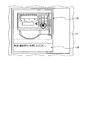
メンテナンス手順データ13bは、自動釣銭機20を構成する硬貨部21及び紙幣部22の各構成要素毎に設けられており、該当する構成要素のメンテナンス操作を手順毎に示す画像データ141(図12参照)と、該手順毎の文言データ142(図12参照)とを有している。かかるメンテナンス操作としては、該当部分の汚れを取る等の清掃操作や、該当部分の交換を行う交換操作等を含むものであり、エラーが発生したときにそのエラー状態を正常状態へ復帰させるためのエラー解除操作とは異なるものである。
図2は、図1に示した制御部12が実施するエラー解除操作表示処理の処理内容を示すフローチャートである。
このエラー解除操作表示処理において制御部12は、硬貨部21及び紙幣部22のセンサ群21a,22aのいずれかのセンサがエラー発生を検出したか否かを判断する(ステップS101)。より詳細には、制御部12は、自動釣銭機20の金銭制御部24よりエラーが発生した旨の信号が与えられたか否かを判断する。金銭制御部24よりエラーが発生した旨の信号が与えられたものと判断した場合、すなわち硬貨部21及び紙幣部22のセンサ群21a,22aのいずれかのセンサがエラー発生を検出したものと判断した場合(ステップS101:Yes)、制御部12は、エラー発生ユニットを特定する(ステップS102)。
そのようにしてエラー発生ユニットを特定した制御部12は、記憶部13からエラー発生ユニットとなる構成要素のエラー解除操作手順データ13aを読み出し(ステップS103)、表示部11に順次表示させる(ステップS104)。
かかるステップS104の処理について具体的に説明する。尚、ここでは硬貨部21における、硬貨の真偽及び金種を鑑別する検銭部がエラー発生ユニットであるとする。
図3に示すように、制御部12は、最初のエラー解除手順となる自動釣銭機20の画像データ131と、該エラー解除手順に対応した「硬貨部を引き出してください。」の文言データ132とを表示部11に表示させる。かかる最初のエラー解除手順を表示してから所定時間(例えば2秒間~5秒間)の経過後、制御部12は、図4に示すように、第2のエラー解除手順となる自動釣銭機20の画像データ131と、該エラー解除手順に対応した「硬貨部を引き出してください。」の文言データ132とを表示部11に表示させる。
第2のエラー解除手順を表示してから所定時間の経過後、制御部12は、図5に示すように、第3のエラー解除手順となる自動釣銭機20の画像データ131と、該エラー解除手順に対応した「操作表示部を開けてください。」の文言データ132とを表示部11に表示させる。かかる第3のエラー解除手順を表示してから所定時間の経過後、制御部12は、図6に示すように、第4のエラー解除手順となる自動釣銭機20の画像データ131と、該エラー解除手順に対応した「操作表示部を開けてください。」の文言データ132とを表示部11に表示させる。
第4のエラー解除手順を表示してから所定時間の経過後、制御部12は、図7に示すように、第5のエラー解除手順となる自動釣銭機20の画像データ131と、該エラー解除手順に対応した「硬貨検銭搬送部を開けてください。」の文言データ132とを表示部11に表示させる。かかる第5のエラー解除手順を表示してから所定時間の経過後、制御部12は、図8に示すように、第6のエラー解除手順となる自動釣銭機20の画像データ131と、該エラー解除手順に対応した「硬貨検銭搬送部を開けてください。」の文言データ132とを表示部11に表示させる。
第6のエラー解除手順を表示してから所定時間の経過後、制御部12は、図9に示すように、第7のエラー解除手順となる自動釣銭機20の画像データ131と、該エラー解除手順に対応した「硬貨検銭通過センサ部分に残っている硬貨があれば取り除いてください。」の文言データ132とを表示部11に表示させる。かかる第7のエラー解除手順を表示してから所定時間の経過後、制御部12は、図10に示すように、第8のエラー解除手順となる自動釣銭機20の画像データ131と、該エラー解除手順に対応した「検銭部(1)を開け、詰まっている硬貨があれば取り除いてください。」の文言データ132とを表示部11に表示させる。
第8のエラー解除手順を表示してから所定時間の経過後、制御部12は、図11に示すように、第9のエラー解除手順となる自動釣銭機20の画像データ131と、該エラー解除手順に対応した「検銭部(1)を開け、詰まっている硬貨があれば取り除いてください。」の文言データ132とを表示部11に表示させる。この第9のエラー解除手順においては、上記画像データ131及び上記文言データ132とともに、メンテナンス操作用の画像データ141を表示させるための入力部14を表示部11に表示させる。
この入力部14を通じて入力操作された場合、制御部12は、エラー解除操作用の画像データ131を表示させる原因となったエラーに関連するメンテナンス手順データ13bを記憶部13から読み出す。そして、制御部12は、図12に示すように、第1のメンテナンス手順となる自動釣銭機20の画像データ141と、該メンテナンス手順に対応した「手垢汚れをウェス等に無水アルコールをつけて拭き取って下さい。」の文言データ142とを表示部11に表示させる。更に、制御部12は、上記画像データ141及び上記文言データ142とともに、メンテナンス操作用の画像データ141等を閉じてエラー解除操作用の画像データ131等に遷移させるためのキャンセル用入力部15を表示部11に表示させる。
キャンセル用入力部15が操作されることなく第1のメンテナンス手順を表示してから所定時間の経過後、制御部12は、図13に示すように、第2のメンテナンス手順となる自動釣銭機20の画像データ141と、該エラー解除手順に対応した「ベルトを手で回してプーリーを一周させ、溝に黒いカスが付着していればピンセット等で除去して下さい。」の文言データ142とを表示部11に表示させるとともに、キャンセル用入力部15を表示部11に表示させる。
かかる第2のメンテナンス手順でメンテナンス手順データ13bが終了するため、制御部12は、所定時間の経過後、再び第1のメンテナンス手順の画像データ141及び文言データ142を表示することで、メンテナンス手順の表示を繰り返し、キャンセル用入力部15の入力待ちとなる。
そして、キャンセル用入力部15が入力操作されると、制御部12は、図11に示した第9のエラー解除手順を表示部11に表示させる。
ところで、第9のエラー解除手順を表示部11に表示させている場合に、入力部14を通じて入力操作されることなく所定時間を経過すると、制御部12は、図14に示すように、第10のエラー解除手順となる自動釣銭機20の画像データ131と、該エラー解除手順に対応した「検銭部(1)を閉じてください。」の文言データ132とを表示部11に表示させる。
第10のエラー解除手順を表示してから所定時間の経過後、制御部12は、図15に示すように、第11のエラー解除手順となる自動釣銭機20の画像データ131と、該エラー解除手順に対応した「検銭搬送部を閉じてください。」の文言データ132とを表示部11に表示させる。かかる第11のエラー解除手順を表示してから所定時間の経過後、制御部12は、図16に示すように、第12のエラー解除手順となる自動釣銭機20の画像データ131と、該エラー解除手順に対応した「操作表示部を閉じてください。」の文言データ132とを表示部11に表示させる。
第12のエラー解除手順を表示してから所定時間の経過後、制御部12は、図17に示すように、第13のエラー解除手順となる自動釣銭機20の画像データ131と、該エラー解除手順に対応した「硬貨部を戻してください。」の文言データ132とを表示部11に表示させる。かかる第13のエラー解除手順を表示してから所定時間の経過後、制御部12は、図18に示すように、第14のエラー解除手順となる自動釣銭機20の画像データ131と、該エラー解除手順に対応した「硬貨部を戻してください。」の文言データ132とを表示部11に表示させる。
第14のエラー解除手順を表示してから所定時間の経過後、制御部12は、図19に示すように、第15のエラー解除手順となる自動釣銭機20の画像データ131と、該エラー解除手順に対応した「取消・復旧ボタンを押してください。」の文言データ132とを表示部11に表示させることにより、上記ステップS104の処理を行う。
かかるステップS104の処理を行い、制御部12は、操作入力部23を構成する取消・復旧ボタンが押下操作されたか否かを判断することで、表示が終了したか否かを判断する(ステップS105)。
表示が終了したものと判断した場合(ステップS105:Yes)、制御部12は、正常状態に復帰したものとして表示部11に待機表示をさせ(ステップS106)、その後にエラー解除手順をリターンさせて今回の処理を終了する。
以上説明したように、本実施の形態である金銭処理装置用表示システムによれば、制御部12が、自動釣銭機20でエラーが生じたことがセンサ群21a,22aを通じて検出された場合、該エラーに対応するエラー解除操作手順データ13aを記憶部13から読み出すとともに、エラー解除操作用の画像データ131をエラー解除操作の進捗の各段階毎に表示部11に順次表示させるので、取扱説明書等を用意させる必要もなく、操作者に表示部11の表示にしたがってエラー解除操作を行わせることができる。しかも制御部12は、エラー解除操作用の画像データ131を表示部11に順次表示させる際に、メンテナンス操作用の画像データ141を表示させるための入力部14を表示部11に表示させ、入力部14を通じて入力操作された場合に、エラー解除操作用の画像データ131を表示させる原因となったエラーに関連するメンテナンス手順データ13bを記憶部13から読み出すとともに、メンテナンス操作用の画像データ141を表示部11に表示させるので、表示部11の表示に従って操作者にメンテナンス操作を行わせることができる。従って、エラー解除の操作性及び利便性を向上させつつ、将来的なエラーの発生を必要に応じて低減させることができる。
ところで、上記メンテナンス操作用の画像データ141等を表示部11に表示させて、操作者にメンテナンス操作を行わせることにより、硬貨部21及び紙幣部22のセンサ群21a,22aのいずれかのセンサが新たなエラーの発生を検出する可能性がある。このように新たなエラーが発生が検出された場合、制御部12は、新たなエラーを操作中エラーとして、エラー解除操作用の画像データ131を表示させる原因となったエラー(上記エラー解除操作表示処理におけるステップS101で検出されたエラーであり、以下、実エラーとも称する)と区別することが好ましい。このように実エラーと操作中エラーとを区別することで、自動釣銭機20の運用により生ずるエラーの回数を正確に認識することができる。
実エラーと操作中エラーとの区別については次のようにして行うことができる。すなわち、制御部12が、実エラー及び操作中エラーをともに履歴情報として記録する場合、該操作中エラーについては予め決められた印を付与して記録することにより区別することができる。また制御部12は、操作中エラーについては履歴情報に記録しないことで、操作中エラーを実エラーと区別することができる。
このような制御部12は、エラー解除操作表示処理において、入力部14を通じて入力操作されてから自動釣銭機20が正常状態に復帰するまで、硬貨部21及び紙幣部22のセンサ群21a,22aにより検出された新たなエラーを操作中エラーとすることが好ましい。ここで自動釣銭機20が正常状態に復帰したものと判断するには、上述したように操作入力部23を構成する取消・復旧ボタンが押下操作された場合でもよいし、それ以外に、電源がオフからオンに切り替わった場合、リセット指示が上位機器であるPOSレジスタ装置10から与えられた場合、硬貨部21及び紙幣部22の構成要素が筐体にセットされたことが検知された場合、あるいはこれらの操作の組み合わせが成立した場合等であってもよい。
以上、本発明の好適な実施の形態について説明したが、本発明はこれに限定されるものではなく、種々の変更を行うことができる。
上述した実施の形態では、金銭処理装置用表示システムがPOSレジスタ装置10により構成されていたが、本発明においては、金銭処理装置用表示システムを構成する表示部は、操作者が携帯する例えばタブレット等の携帯情報端末であってもよい。
上述した実施の形態では、エラー解除操作表示処理において、キャンセル用入力部15が操作された場合に、メンテナンス操作用の画像データ141を表示させる前の第9のエラー解除手順のエラー解除操作用の画像データ131を表示させるようにしたが、本発明においては、メンテナンス操作用の画像データ141を表示させた後の画像の遷移先については特に限定されるものではない。従って、メンテナンス手順データ13b(メンテナンス操作用の画像データ141)を表示させた後は、正常状態に復帰したものとして待機表示をさせてもよいし、上記の例であれば第10のエラー解除手順のエラー解除操作用の画像データ131等を表示させるようにしてもよい。
上述した実施の形態では、第9のエラー解除手順においてメンテナンス操作用の画像データ141を表示させるための入力部14を表示させていたが、本発明においては、メンテナンス操作用の画像データを表示させるための入力部を、任意のエラー解除手順におけるエラー解除操作用の画像データに付加してもよく、特に限定されるものではない。
本発明においては、金銭処理装置が操作者の訓練を目的として模擬的にエラーを発生させる機能を有するものであってもよい。このように模擬的にエラーを発生させる場合、かかる模擬的なエラーについても操作中エラーと同様に、実エラーと区別することが好ましい。
10…POSレジスタ装置、11…表示部、12…制御部、13…記憶部、13a…エラー解除操作手順データ、13b…メンテナンス手順データ、131…エラー解除操作用の画像データ、132…エラー解除操作用の文言データ、14…入力部、141…メンテナンス操作用の画像データ、142…メンテナンス操作用の文言データ、15…キャンセル用入力部、20…自動釣銭機、21…硬貨部、21a…センサ群、21b…アクチュエータ群、22…紙幣部、22a…センサ群、22b…アクチュエータ群、23…操作入力部、24…金銭制御部。
Claims (6)
- 金銭の入出金を処理する金銭処理装置に電気的に接続され、かつ所定の情報を表示する表示手段と、
前記金銭処理装置で生じたエラーを解除して正常状態へ復帰するためのエラー解除操作が、該エラー解除操作の進捗の各段階に応じて複数用意されたエラー解除操作用の画像データを含むエラー解除操作手順データを格納する記憶手段と、
前記金銭処理装置でエラーが生じたことが検出手段を通じて検出された場合、該エラーに対応するエラー解除操作手順データを前記記憶手段から読み出すとともに、前記エラー解除操作用の画像データをエラー解除操作の進捗の各段階毎に前記表示手段に順次表示させる制御手段と
を備えた金銭処理装置用表示システムであって、
前記記憶手段は、前記エラー解除操作とは異なってエラーの発生の原因を取り除くためのメンテナンス操作が、該メンテナンス操作の進捗の各段階に応じて複数用意されたメンテナンス操作用の画像データを含むメンテナンス手順データを有し、
前記制御手段は、前記エラー解除操作用の画像データを前記表示手段に順次表示させる際に、前記メンテナンス操作用の画像データを表示させるための入力部を前記表示手段に表示させるものであり、前記入力部を通じて入力操作された場合に、該エラー解除操作用の画像データを表示させる原因となったエラーに関連するメンテナンス手順データを前記記憶手段から読み出すとともに、前記メンテナンス操作用の画像データを前記表示手段に表示させることを特徴とする金銭処理装置用表示システム。 - 前記エラー解除操作用の画像データは、エラー解除操作の進捗の各段階で操作者が目にする前記金銭処理装置の状況のものであって、エラー解除操作の進捗の各段階に応じて複数用意されており、
前記メンテナンス操作用の画像データは、メンテナンス操作の進捗の各段階で操作者が目にする前記金銭処理装置の状況のものであって、メンテナンス操作の進捗の各段階に応じて複数用意されていることを特徴とする請求項1に記載の金銭処理装置用表示システム。 - 前記制御手段は、前記メンテナンス操作用の画像データを前記表示手段に表示させている際に新たなエラーが生じたことが前記検出手段を通じて検出された場合、該新たなエラーを操作中エラーとして、前記エラー解除操作用の画像データを表示させる原因となったエラーと区別することを特徴とする請求項1又は請求項2に記載の金銭処理装置用表示システム。
- 前記制御手段は、前記操作中エラーを前記エラー解除操作用の画像データを表示させる原因となったエラーとともに履歴情報として記録する場合、該操作中エラーについては予め決められた印を付与して記録することで、区別することを特徴とする請求項3に記載の金銭処理装置用表示システム。
- 前記制御手段は、前記操作中エラーについては履歴情報に記録しないことで、区別することを特徴とする請求項3に記載の金銭処理装置用表示システム。
- 前記制御手段は、前記入力部を通じて入力操作されてから前記金銭処理装置が前記正常状態に復帰するまでに前記検出手段により検出された新たなエラーを前記操作中エラーとすることを特徴とする請求項3~5のいずれか1つに記載の金銭処理装置用表示システム。
Applications Claiming Priority (2)
| Application Number | Priority Date | Filing Date | Title |
|---|---|---|---|
| JP2019025836A JP7196671B2 (ja) | 2019-02-15 | 2019-02-15 | 金銭処理装置用表示システム |
| JP2019-025836 | 2019-02-15 |
Publications (1)
| Publication Number | Publication Date |
|---|---|
| WO2020166217A1 true WO2020166217A1 (ja) | 2020-08-20 |
Family
ID=72043908
Family Applications (1)
| Application Number | Title | Priority Date | Filing Date |
|---|---|---|---|
| PCT/JP2019/050669 Ceased WO2020166217A1 (ja) | 2019-02-15 | 2019-12-24 | 金銭処理装置用表示システム |
Country Status (2)
| Country | Link |
|---|---|
| JP (1) | JP7196671B2 (ja) |
| WO (1) | WO2020166217A1 (ja) |
Citations (4)
| Publication number | Priority date | Publication date | Assignee | Title |
|---|---|---|---|---|
| JP2013257622A (ja) * | 2012-06-11 | 2013-12-26 | Oki Electric Ind Co Ltd | 現金処理装置 |
| JP2014010697A (ja) * | 2012-06-29 | 2014-01-20 | Glory Ltd | 貨幣処理機および貨幣処理システム |
| JP2015069477A (ja) * | 2013-09-30 | 2015-04-13 | 富士電機株式会社 | 釣銭機の保守作業支援システム |
| JP2018116327A (ja) * | 2017-01-16 | 2018-07-26 | グローリー株式会社 | 有価媒体処理装置、有価媒体処理システム、及び、有価媒体処理装置のエラー解除監視方法 |
-
2019
- 2019-02-15 JP JP2019025836A patent/JP7196671B2/ja active Active
- 2019-12-24 WO PCT/JP2019/050669 patent/WO2020166217A1/ja not_active Ceased
Patent Citations (4)
| Publication number | Priority date | Publication date | Assignee | Title |
|---|---|---|---|---|
| JP2013257622A (ja) * | 2012-06-11 | 2013-12-26 | Oki Electric Ind Co Ltd | 現金処理装置 |
| JP2014010697A (ja) * | 2012-06-29 | 2014-01-20 | Glory Ltd | 貨幣処理機および貨幣処理システム |
| JP2015069477A (ja) * | 2013-09-30 | 2015-04-13 | 富士電機株式会社 | 釣銭機の保守作業支援システム |
| JP2018116327A (ja) * | 2017-01-16 | 2018-07-26 | グローリー株式会社 | 有価媒体処理装置、有価媒体処理システム、及び、有価媒体処理装置のエラー解除監視方法 |
Also Published As
| Publication number | Publication date |
|---|---|
| JP7196671B2 (ja) | 2022-12-27 |
| JP2020135227A (ja) | 2020-08-31 |
Similar Documents
| Publication | Publication Date | Title |
|---|---|---|
| JP5194048B2 (ja) | チェックアウト端末およびその制御プログラム | |
| JP2010267152A (ja) | 現金処理機 | |
| US20240249580A1 (en) | Change machine | |
| JP2013134569A (ja) | 取引データ処理装置、貨幣取引システムおよび貨幣取引方法 | |
| JP2009059191A (ja) | 硬貨処理装置および硬貨処理方法 | |
| JP5359720B2 (ja) | 金銭処理装置 | |
| JP7196671B2 (ja) | 金銭処理装置用表示システム | |
| JP5663547B2 (ja) | 貨幣管理装置およびそのプログラム | |
| JP6996856B2 (ja) | 商品販売データ処理装置、及び表示制御プログラム | |
| CN106169202B (zh) | 纸币处理装置 | |
| JP2017073063A (ja) | 決済装置とその制御プログラム、ならびにチェックアウトシステム | |
| JP6693122B2 (ja) | 商品販売データ処理装置 | |
| JP7314977B2 (ja) | 精算システム、締め方法及びプログラム | |
| JP6003729B2 (ja) | 釣銭機 | |
| CN113450514B (zh) | 读取装置和存储介质 | |
| JP6250573B2 (ja) | 金銭処理装置 | |
| JP2020021349A (ja) | 金銭処理装置用表示システム | |
| JP6576687B2 (ja) | 貨幣処理システム及び貨幣処理方法 | |
| TWI584231B (zh) | Paper class payment device | |
| JP7585810B2 (ja) | 貨幣処理装置 | |
| JP5499192B2 (ja) | チェックアウト端末およびその制御プログラム | |
| JP2008083869A (ja) | 釣銭機、精算装置、釣銭出金システム、釣銭出金方法、釣銭出金プログラム | |
| US20250252415A1 (en) | Payment device, method, and storage medium | |
| JP2014106792A (ja) | 紙幣処理装置 | |
| JP6022238B2 (ja) | 貨幣処理機および貨幣処理システム |
Legal Events
| Date | Code | Title | Description |
|---|---|---|---|
| 121 | Ep: the epo has been informed by wipo that ep was designated in this application |
Ref document number: 19915436 Country of ref document: EP Kind code of ref document: A1 |
|
| NENP | Non-entry into the national phase |
Ref country code: DE |
|
| 122 | Ep: pct application non-entry in european phase |
Ref document number: 19915436 Country of ref document: EP Kind code of ref document: A1 |