WO2020162448A1 - 固体潤滑転がり軸受 - Google Patents
固体潤滑転がり軸受 Download PDFInfo
- Publication number
- WO2020162448A1 WO2020162448A1 PCT/JP2020/004103 JP2020004103W WO2020162448A1 WO 2020162448 A1 WO2020162448 A1 WO 2020162448A1 JP 2020004103 W JP2020004103 W JP 2020004103W WO 2020162448 A1 WO2020162448 A1 WO 2020162448A1
- Authority
- WO
- WIPO (PCT)
- Prior art keywords
- bearing
- solid lubricant
- solid
- cage
- diameter surface
- Prior art date
- Legal status (The legal status is an assumption and is not a legal conclusion. Google has not performed a legal analysis and makes no representation as to the accuracy of the status listed.)
- Ceased
Links
Images




Classifications
-
- F—MECHANICAL ENGINEERING; LIGHTING; HEATING; WEAPONS; BLASTING
- F16—ENGINEERING ELEMENTS AND UNITS; GENERAL MEASURES FOR PRODUCING AND MAINTAINING EFFECTIVE FUNCTIONING OF MACHINES OR INSTALLATIONS; THERMAL INSULATION IN GENERAL
- F16C—SHAFTS; FLEXIBLE SHAFTS; ELEMENTS OR CRANKSHAFT MECHANISMS; ROTARY BODIES OTHER THAN GEARING ELEMENTS; BEARINGS
- F16C19/00—Bearings with rolling contact, for exclusively rotary movement
- F16C19/02—Bearings with rolling contact, for exclusively rotary movement with bearing balls essentially of the same size in one or more circular rows
- F16C19/04—Bearings with rolling contact, for exclusively rotary movement with bearing balls essentially of the same size in one or more circular rows for radial load mainly
- F16C19/06—Bearings with rolling contact, for exclusively rotary movement with bearing balls essentially of the same size in one or more circular rows for radial load mainly with a single row or balls
-
- F—MECHANICAL ENGINEERING; LIGHTING; HEATING; WEAPONS; BLASTING
- F16—ENGINEERING ELEMENTS AND UNITS; GENERAL MEASURES FOR PRODUCING AND MAINTAINING EFFECTIVE FUNCTIONING OF MACHINES OR INSTALLATIONS; THERMAL INSULATION IN GENERAL
- F16C—SHAFTS; FLEXIBLE SHAFTS; ELEMENTS OR CRANKSHAFT MECHANISMS; ROTARY BODIES OTHER THAN GEARING ELEMENTS; BEARINGS
- F16C33/00—Parts of bearings; Special methods for making bearings or parts thereof
- F16C33/30—Parts of ball or roller bearings
- F16C33/38—Ball cages
- F16C33/41—Ball cages comb-shaped
-
- F—MECHANICAL ENGINEERING; LIGHTING; HEATING; WEAPONS; BLASTING
- F16—ENGINEERING ELEMENTS AND UNITS; GENERAL MEASURES FOR PRODUCING AND MAINTAINING EFFECTIVE FUNCTIONING OF MACHINES OR INSTALLATIONS; THERMAL INSULATION IN GENERAL
- F16C—SHAFTS; FLEXIBLE SHAFTS; ELEMENTS OR CRANKSHAFT MECHANISMS; ROTARY BODIES OTHER THAN GEARING ELEMENTS; BEARINGS
- F16C33/00—Parts of bearings; Special methods for making bearings or parts thereof
- F16C33/30—Parts of ball or roller bearings
- F16C33/46—Cages for rollers or needles
- F16C33/49—Cages for rollers or needles comb-shaped
-
- F—MECHANICAL ENGINEERING; LIGHTING; HEATING; WEAPONS; BLASTING
- F16—ENGINEERING ELEMENTS AND UNITS; GENERAL MEASURES FOR PRODUCING AND MAINTAINING EFFECTIVE FUNCTIONING OF MACHINES OR INSTALLATIONS; THERMAL INSULATION IN GENERAL
- F16C—SHAFTS; FLEXIBLE SHAFTS; ELEMENTS OR CRANKSHAFT MECHANISMS; ROTARY BODIES OTHER THAN GEARING ELEMENTS; BEARINGS
- F16C33/00—Parts of bearings; Special methods for making bearings or parts thereof
- F16C33/30—Parts of ball or roller bearings
- F16C33/66—Special parts or details in view of lubrication
-
- F—MECHANICAL ENGINEERING; LIGHTING; HEATING; WEAPONS; BLASTING
- F16—ENGINEERING ELEMENTS AND UNITS; GENERAL MEASURES FOR PRODUCING AND MAINTAINING EFFECTIVE FUNCTIONING OF MACHINES OR INSTALLATIONS; THERMAL INSULATION IN GENERAL
- F16C—SHAFTS; FLEXIBLE SHAFTS; ELEMENTS OR CRANKSHAFT MECHANISMS; ROTARY BODIES OTHER THAN GEARING ELEMENTS; BEARINGS
- F16C33/00—Parts of bearings; Special methods for making bearings or parts thereof
- F16C33/72—Sealings
- F16C33/76—Sealings of ball or roller bearings
- F16C33/78—Sealings of ball or roller bearings with a diaphragm, disc, or ring, with or without resilient members
Definitions
- the present invention relates to a rolling bearing equipped with a solid lubricant that is used in environments such as high temperatures and vacuum.
- Solid lubrication rolling bearings are used in high temperature atmospheres and vacuum environments where grease or lubricating oil cannot be used as a lubricant.
- Patent Document 1 as a component for separating the rolling element and the solid lubricant in the circumferential direction, a substantially U-shaped "regulating member" is adopted, but the component is asymmetrical in the axial direction of the bearing and is a separate component. Therefore, during operation, the bearing may slide in an unstable posture against the bearing ring or the sealing plate, and the smooth rotation of the bearing may be hindered.
- Patent Document 2 although a cage having a substantially sheathed pear shape is adopted, the cage of the cage surrounds the rolling element and the solid lubricant in both the axial direction and the radial direction. It is difficult to make the diameter larger than that of the rolling element, and the wear life of the solid lubricant may be shortened.
- the transfer of solid lubricant and the generation of lubricant powder mainly depend on the sliding of the rolling element and the solid lubricant, in order to make up for the lack of lubricant in the initial stage of operation, the rolling element should also be solid beforehand. It is necessary to form a lubricating film.
- Another object of the present invention is to provide a structure capable of supplying various lubricants.
- the present invention provides an inner ring, an outer ring, a plurality of rolling elements, at least one solid lubricant located between the rolling elements, and a rolling element and a solid lubricant in the circumferential direction.
- the cage is composed of at least one annular portion and a plurality of column portions that extend in the axial direction from the annular portion as a starting point, and the solid lubricant is applied to the inner surface of the outer ring or the inner ring.
- the configuration is such that at least one of the outer diameter surfaces is guided.
- a solid-lubricated rolling bearing capable of supplying a sufficient amount of lubricant to the inside of the bearing at the initial stage of operation without hindering the rotation of the component parts of the bearing and limiting the shape and size of the solid lubricant is provided. Can be provided.
- the solid lubricant also slides with the raceway ring, and a sufficient amount of lubricant is supplied to the inside of the bearing at the beginning of operation. Will be done. Further, by arranging the cage to be guided by at least one of the inner diameter surface of the outer ring and the outer diameter surface of the inner ring, the behavior of the cage during operation can be further stabilized.
- the solid lubricant can be further increased.
- the annular portion it is necessary to arrange the annular portion immediately below the inner diameter surface of the outer ring or directly above the outer diameter surface of the inner ring, which naturally limits the width of the solid lubricant.
- the annular portion can be arranged outside the inner diameter surface of the outer ring and the outer diameter surface of the inner ring.
- the behavior of the cage during operation is further stabilized by adopting a structure in which the cage is guided by the bearing ring that fixes the sealing plate.
- the cage can be guided by both the bearing ring and the sealing plate.
- the components of the bearing do not hinder the rotation, the shape and size of the solid lubricant are less likely to be limited, and a sufficient lubricant is supplied to the inside of the bearing at the initial stage of operation. As a result, it is possible to provide a solid-lubricated rolling bearing which has a long life and can be smoothly rotated.
- FIG. 6 is a perspective view of the holder alone of FIG. 5.
- FIG. 6 is a radial cross-sectional view of the bearing of FIG. 5.
- 1 to 4 show an embodiment in which the present invention is applied to a sealed deep groove ball bearing.
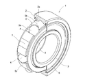
- FIG. 1 is a perspective view of a sealed deep groove ball bearing 1 to which the present invention is applied.
- the outer ring 2 and the sealing plate 6 are shown by removing the front half of the drawing.
- the bearing 1 includes an outer ring 2 having an outer raceway surface 2a on an inner peripheral surface, an inner race 3 having an inner raceway surface 3a on an outer peripheral surface, a rolling element 4, and a solid lubricant 7 located between the rolling elements 4. , A cage 5 that separates the rolling elements 4 in the circumferential direction, and an annular plate 8 having the same shape as the annular portion 5a on the axially opposite side of the annular portion 5a of the retainer 5, on both sides of the outer ring 2.
- the sealing plate 6 is fixed.
- the outer diameter end of the sealing plate 6 is press-fitted and fixed in the peripheral groove formed on the inner peripheral surface of the outer ring 2, and the inner diameter end thereof is close to the outer peripheral surface of the inner ring 3 to form a non-contact seal.
- the seal plate 6 may be a contact seal type in which the inner diameter end of the seal plate 6 is in sliding contact with the outer peripheral surface of the inner ring 3.
- the outer ring 2, the inner ring 3, the cage 5, and the annular plate 8 are made of a steel material, for example, martensitic stainless steel such as SUS440C.
- the rolling element 4 is made of ceramics, and as the ceramics, for example, silicon nitride can be used. When the rolling elements 4 are not made of ceramics, it is preferable to form a coating film made of a solid lubricating material such as graphite on the surface thereof.
- the sealing plate 6 is preferably made of a steel material, for example, austenitic stainless steel such as SUS304 having excellent corrosion resistance.
- the cage 5 is composed of one annular portion 5a and three pillar portions 3b extending in the axial direction starting from the outer diameter side of the annular portion 5a.
- the contact surface of the column portion 5b with the rolling element 4 has a concave surface shape for receiving the rolling element 4.
- the outer diameter surface of the column portion 5b is a partial cylindrical surface corresponding to the inner diameter surface of the outer ring 2.
- the solid lubricant 7 is made of, for example, a graphite-based, tungsten disulfide-based, or molybdenum disulfide-based solid lubricant material, has a plate shape curved along the shape of the bearing ring, and as shown in FIG. It extends beyond both ends of the faces 2a, 3a and its axial movement is limited by the annular portion 5a of the retainer 5 and the annular plate 8.
- the outer diameter surface and the inner diameter surface of the solid lubricant 7 are guided by the inner diameter surface of the outer ring 2 and the outer diameter surface of the inner ring 3, respectively, and the guided surface of the cage 5 is the outer diameter surface of the column portion 5b.
- the inner ring 3 is guided by the inner diameter surface of the outer ring 2 and is not in contact with the inner ring 3.
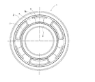
- FIG. 4 is a side view of the bearing 1 of FIG. 1, and for convenience of explanation, the sealing plate 6 and the annular plate 8 on the front side of the drawing are omitted.
- the guide surfaces of the solid lubricant 7 and the cage 5 are formed along the inner diameter surface of the outer ring 2 or the outer diameter surface of the inner ring 3.
- FIG. 5 is a perspective view of a sealed deep groove ball bearing 9 to which the present invention is applied.
- the outer ring 2 and the sealing plate 6 are shown with the front half of the paper surface removed.
- the parts common to those of the embodiment shown in FIGS. 1 to 4 are designated by the same reference numerals, and the description thereof will be appropriately omitted.
- the bearing 9 includes an outer ring 2 and an inner ring 3 made of stainless steel, a rolling element 4 made of ceramics, a solid lubricant 7 made of a graphite-based solid lubricating material located between the rolling elements 4, and a rolling element. It has a cage 5 made of stainless steel plate and spaced apart from each other in the circumferential direction.
- the cage 5 is composed of one annular portion 5a and three pillar portions 5b extending in the axial direction from the inner diameter side of the annular portion 5a as a starting point.
- the contact surface of the column portion 5b with the rolling element 4 has a planar shape facing the rolling element 4.
- the inner diameter surface of the column portion 5b has a planar shape that faces the outer diameter surface of the inner ring 3.
- the present invention is not limited to ball bearings, but can be applied to roller bearings.
- the material and shape of the components are not limited to the above.
- Steel balls made of stainless steel or bearing steel, tungsten disulfide-based or molybdenum disulfide-based solid lubricants, as well as cylindrical members were turned.
- a machined cage can also be used.
Landscapes
- Engineering & Computer Science (AREA)
- General Engineering & Computer Science (AREA)
- Mechanical Engineering (AREA)
- Rolling Contact Bearings (AREA)
- Sealing Of Bearings (AREA)
Abstract
固体潤滑転がり軸受の構成部品が回転を阻害することなく、また、固体潤滑剤の形状や大きさが制限されにくく、運転初期の軸受内部に潤沢な潤滑剤を供給可能な構成を提供することを課題とする。内輪3と、外輪2と、複数の転動体4と、転動体4の間に位置する少なくとも1つの固体潤滑剤7と、転動体4および固体潤滑剤7を周方向に離間する保持器5を有する転がり軸受において、保持器5が少なくとも1つの円環部5aと、円環部5aを起点に軸方向に伸びる複数の柱部5bで構成され、保持器5は、柱部5bの外径面が外輪2の内径面によって案内され、固体潤滑剤7を外輪2の内径面または内輪3の外径面の少なくとも一方で案内する構成を採用した。
Description
この発明は、高温や真空等の環境下で使用する固体潤滑剤を備えた転がり軸受に関する。
固体潤滑転がり軸受は、潤滑剤としてグリースや潤滑油を使用することができない高温雰囲気や真空雰囲気等で使用される。
この種の固体潤滑転がり軸受として、従来、特許文献1や特許文献2に記載のものが知られている。いずれの構成も2つの転動体の間に固体潤滑剤を介在させ、固体潤滑剤が転動体や軌道輪と摺動することで、潤滑剤が相手部品に移着または潤滑粉が生成されて軸受内部が潤滑される。
ところで、特許文献1では、転動体および固体潤滑剤を周方向に離間する部品として、略コの字形の"規制部材"を採用しているが、軸受の軸方向に非対称形状かつ分離独立した部品であるため、運転中に不安定な姿勢で軌道輪や密封板と摺動し、軸受の円滑な回転を阻害する恐れがある。
また、特許文献2では、略さやえんどう形の保持器を採用しているが、保持器のポケットが転動体と固体潤滑剤を軸方向にも径方向にも取り囲む構成であるため、固体潤滑剤の直径を転動体よりも大きくすることが困難であり、固体潤滑剤の摩滅寿命が短くなる恐れがある。また、固体潤滑剤の移着や潤滑粉の生成は、主に転動体と固体潤滑剤の摺動に頼る構成であることから、運転初期の潤滑剤不足を補うため、転動体にも予め固体潤滑膜を成膜する必要がある。
そこで、この発明は、固体潤滑剤を備えた転がり軸受において、軸受の構成部品が回転を阻害することなく、また、固体潤滑剤の形状や大きさが制限されにくく、運転初期の軸受内部に潤沢な潤滑剤を供給可能な構成を提供しようとするものである。
前記の課題を解決するために、この発明は、内輪と、外輪と、複数の転動体と、転動体の間に位置する少なくとも1つの固体潤滑剤と、転動体および固体潤滑剤を周方向に離間する保持器を有する転がり軸受において、保持器が少なくとも1つの円環部と、円環部を起点に軸方向に伸びる複数の柱部で構成され、固体潤滑剤を外輪の内径面または内輪の外径面の少なくとも一方で案内する構成を採用したものである。
かかる構成により、軸受の構成部品が回転を阻害することなく、また、固体潤滑剤の形状や大きさが制限されにくく、運転初期の軸受内部に潤沢な潤滑剤を供給可能な固体潤滑転がり軸受を提供することができる。
すなわち、柱部が円環部によって結合された保持器を採用することで、特許文献1の構成で懸念される"規制部材"の不安定な挙動が抑制される。また、軌道面から離れた位置に円環部を設け、円環部から伸びる柱部だけを転動体および固体潤滑剤の間に挿入することにより、特許文献2のように固体潤滑剤の形状や大きさが大幅に制限されることがない。
さらに、固体潤滑剤を外輪の内径面または内輪の外径面の少なくとも一方で案内することにより、固体潤滑剤が軌道輪とも摺動する構成となり、運転初期の軸受内部に潤沢な潤滑剤が供給されることになる。
また、保持器を外輪の内径面または内輪の外径面の少なくとも一方で案内する構成とすることにより、運転中の保持器の挙動を一層安定化させることができる。
また、保持器を外輪の内径面または内輪の外径面の少なくとも一方で案内する構成とすることにより、運転中の保持器の挙動を一層安定化させることができる。
さらに、保持器の被案内面を柱部の外径面または内径面とすることにより、固体潤滑剤を一層大きくすることができる。円環部の外径面または内径面を案内する場合、円環部を外輪内径面の直下または内輪外径面の直上に配置する必要があり、自ずと固体潤滑剤の幅寸法が制限されるが、かかる構成によれば、外輪内径面や内輪外径面の外側に円環部を配置することができる。
さらにまた、密封板を有する軸受において、密封板を固定する側の軌道輪で保持器を案内する構成とすることにより、運転中の保持器の挙動がより一層安定化する。密封板を有する軸受においては、保持器の端面と密封板の内壁が摺動し得るため、保持器は軌道輪と密封板の双方で案内され得るが、保持器を密封板を固定する側の軌道輪で案内することにより、保持器が回転輪と固定輪の双方に案内されることがなく、運転中の保持器の挙動がより一層安定化する。
以上のように、この発明によれば、軸受の構成部品が回転を阻害することなく、また、固体潤滑剤の形状や大きさが制限されにくく、運転初期の軸受内部に潤沢な潤滑剤を供給可能となり、長寿命で円滑に回転可能な固体潤滑転がり軸受を提供することができる。
以下、この発明の実施の形態を添付図面に基づいて説明する。
図1~図4は、この発明を密封形深溝玉軸受に適用した実施形態を示している。
図1は、この発明を適用した密封形深溝玉軸受1の斜視図であり、便宜上、外輪2と密封板6は、紙面手前側半分を除去して表示している。
同軸受1は、内周面に外側軌道面2aを有する外輪2と、外周面に内側軌道面3aを有する内輪3と、転動体4と、転動体4の間に位置する固体潤滑剤7と、転動体4を周方向に離間する保持器5と、保持器5の円環部5aの軸方向反対側に前記円環部5aと同様形状の円環板8を備え、外輪2の両側に密封板6が固定されている。
前記密封板6は、その外径端が外輪2の内周面に形成された周溝に圧入固定され、その内径端が内輪3の外周面に近接して非接触シールを形成している。なお、高温環境で使用されない軸受等では、密封板6として、その内径端を内輪3の外周面に摺接させる接触シールタイプを使用することもできる。
外輪2、内輪3、保持器5および円環板8は、鋼材料、例えばSUS440C等のマルテンサイト系ステンレス鋼で形成される。転動体4は、セラミックスで形成され、セラミックスとしては、例えば窒化ケイ素を使用することができる。転動体4をセラミックスで形成しない場合には、その表面にグラファイト等の固体潤滑材料からなる被膜を形成するのが好ましい。密封板6は、鋼材料で形成し、例えば耐食性に優れるSUS304等のオーステナイト系ステンレス鋼で形成するのが好ましい。
保持器5は、1つの円環部5aと、この円環部5aの外径側を起点に軸方向に伸びる3つの柱部3bで構成されている。柱部5bの転動体4との接触面は、転動体4を受け入れる凹面形状である。また、柱部5bの外径面は、外輪2の内径面に対応した部分円筒面を成している。
固体潤滑剤7は、例えば、グラファイト系、二硫化タングステン系や二硫化モリブデン系の固体潤滑剤材料からなり、軌道輪の形状に沿って湾曲した板状を呈し、図3に示すように、軌道面2a、3aの両端を超えて延在し、軸方向の移動は、保持器5の円環部5aと円環板8によって制限される。
また、固体潤滑剤7の外径面と内径面は、それぞれ外輪2の内径面と内輪3の外径面で案内されるほか、保持器5の被案内面は、柱部5bの外径面となり、外輪2の内径面によって案内され、内輪3とは接触しない構成となっている。
図4は、図1の軸受1の側面図であり、説明の便宜上、紙面手前の密封板6および円環板8を省略している。ここで、固体潤滑剤7と保持器5の案内面は、外輪2の内径面または内輪3の外径面に沿った形状を成している。
次に、図5は、この発明を適用した密封形深溝玉軸受9の斜視図であり、便宜上、外輪2と密封板6は、紙面手前側半分を除去して表示している。図1~4に示した実施形態と共通する部位については同一の符号を付し、適宜説明を省略する。
軸受9は軸受1と同様にステンレス鋼製の外輪2および内輪3と、セラミックス製の転動体4と、転動体4の間に位置するグラファイト系固体潤滑材料からなる固体潤滑剤7と、転動体4を周方向に離間するステンレス鋼板製の保持器5を有する。
保持器5は、1つの円環部5aと、この円環部5aの内径側を起点に軸方向に伸びる3つの柱部5bで構成されている。柱部5bの転動体4との接触面は、転動体4と対向する平面形状である。また、柱部5bの内径面は、内輪3の外径面に対向する平面形状である。
なお、本発明は玉軸受に限定されるものではなく、ころ軸受にも適用することができる。また、構成部品の材質や形状も上記に限定されるものではなく、ステンレス鋼や軸受鋼製の鋼球、二硫化タングステン系や二硫化モリブデン系の固体潤滑剤のほか、円筒部材を旋削加工したもみ抜き保持器を採用することもできる。
1 :密封形深溝玉軸受
2 :外輪
2a :外側軌道面
3 :内輪
3a :内側軌道面
4 :転動体
5 :保持器
5a :円環部
5b :柱部
6 :密封板
7 :固体潤滑剤
8 :円環板
9 :密封形深溝玉軸受
2 :外輪
2a :外側軌道面
3 :内輪
3a :内側軌道面
4 :転動体
5 :保持器
5a :円環部
5b :柱部
6 :密封板
7 :固体潤滑剤
8 :円環板
9 :密封形深溝玉軸受
Claims (4)
- 内輪と、外輪と、複数の転動体と、転動体の間に位置する少なくとも1つの固体潤滑剤と、転動体および固体潤滑剤を周方向に離間する保持器を有する転がり軸受において、
保持器が少なくとも1つの円環部と、円環部を起点に軸方向に伸びる複数の柱部で構成され、固体潤滑剤を外輪の内径面または内輪の外径面の少なくとも一方で案内する固体潤滑転がり軸受。 - 保持器を外輪の内径面または内輪の外径面の少なくとも一方で案内する請求項1に記載の固体潤滑転がり軸受。
- 保持器の被案内面を柱部の外径面または内径面とした請求項2に記載の固体潤滑転がり軸受。
- 密封板を有する軸受において、密封板を固定する側の軌道輪で保持器を案内する請求項2または3記載の固体潤滑転がり軸受。
Applications Claiming Priority (2)
| Application Number | Priority Date | Filing Date | Title |
|---|---|---|---|
| JP2019020534A JP2020128758A (ja) | 2019-02-07 | 2019-02-07 | 固体潤滑転がり軸受 |
| JP2019-020534 | 2019-02-07 |
Publications (1)
| Publication Number | Publication Date |
|---|---|
| WO2020162448A1 true WO2020162448A1 (ja) | 2020-08-13 |
Family
ID=71948324
Family Applications (1)
| Application Number | Title | Priority Date | Filing Date |
|---|---|---|---|
| PCT/JP2020/004103 Ceased WO2020162448A1 (ja) | 2019-02-07 | 2020-02-04 | 固体潤滑転がり軸受 |
Country Status (3)
| Country | Link |
|---|---|
| JP (1) | JP2020128758A (ja) |
| TW (1) | TW202043635A (ja) |
| WO (1) | WO2020162448A1 (ja) |
Citations (5)
| Publication number | Priority date | Publication date | Assignee | Title |
|---|---|---|---|---|
| JPH06509628A (ja) * | 1991-08-21 | 1994-10-27 | バランスド エンジンズ インコーポレイテッド | 潤滑スペーサ及び非潤滑スペーサを有する軸受 |
| JPH0949525A (ja) * | 1995-05-30 | 1997-02-18 | Ntn Corp | 固体潤滑転がり軸受 |
| JP2008064280A (ja) * | 2006-09-11 | 2008-03-21 | Nsk Ltd | 転がり軸受 |
| JP2008267401A (ja) * | 2007-04-16 | 2008-11-06 | Nsk Ltd | 玉軸受 |
| JP2018091399A (ja) * | 2016-12-02 | 2018-06-14 | Ntn株式会社 | 転がり軸受用保持器及びそれを備えた転がり軸受 |
-
2019
- 2019-02-07 JP JP2019020534A patent/JP2020128758A/ja active Pending
-
2020
- 2020-02-04 WO PCT/JP2020/004103 patent/WO2020162448A1/ja not_active Ceased
- 2020-02-05 TW TW109103537A patent/TW202043635A/zh unknown
Patent Citations (5)
| Publication number | Priority date | Publication date | Assignee | Title |
|---|---|---|---|---|
| JPH06509628A (ja) * | 1991-08-21 | 1994-10-27 | バランスド エンジンズ インコーポレイテッド | 潤滑スペーサ及び非潤滑スペーサを有する軸受 |
| JPH0949525A (ja) * | 1995-05-30 | 1997-02-18 | Ntn Corp | 固体潤滑転がり軸受 |
| JP2008064280A (ja) * | 2006-09-11 | 2008-03-21 | Nsk Ltd | 転がり軸受 |
| JP2008267401A (ja) * | 2007-04-16 | 2008-11-06 | Nsk Ltd | 玉軸受 |
| JP2018091399A (ja) * | 2016-12-02 | 2018-06-14 | Ntn株式会社 | 転がり軸受用保持器及びそれを備えた転がり軸受 |
Also Published As
| Publication number | Publication date |
|---|---|
| TW202043635A (zh) | 2020-12-01 |
| JP2020128758A (ja) | 2020-08-27 |
Similar Documents
| Publication | Publication Date | Title |
|---|---|---|
| EP2754909A2 (en) | Rolling bearing unit | |
| JP2510374B2 (ja) | 転動子を有する滑り・転がり兼用型軸受 | |
| JP2005321049A (ja) | ころ軸受 | |
| WO2013191238A1 (ja) | 転がり軸受及び工作機械用主軸装置 | |
| JP2008240796A (ja) | シール付きアンギュラ玉軸受及び主軸装置 | |
| JP6565366B2 (ja) | アンギュラ玉軸受 | |
| JP2006022891A (ja) | 玉軸受用保持器 | |
| KR20210044827A (ko) | 롤링 베어링 및 이 롤링 베어링을 구비한 스핀들 장치 | |
| JP2008196582A (ja) | 遊星回転体用円錐ころ軸受 | |
| JP2008196583A (ja) | 遊星回転体用円錐ころ軸受 | |
| JP2005133818A (ja) | 転がり軸受 | |
| JP2006329218A (ja) | 転がり軸受用保持器 | |
| JP2016153685A (ja) | 転がり軸受 | |
| WO2020162222A1 (ja) | 固体潤滑転がり軸受 | |
| JP2009115187A (ja) | 転がり部材 | |
| JP2020128758A (ja) | 固体潤滑転がり軸受 | |
| JP4661424B2 (ja) | 回転支持部 | |
| JP2008032089A (ja) | スラストころ軸受 | |
| WO2021187032A1 (ja) | 固体潤滑転がり軸受 | |
| WO2021171879A1 (ja) | 固体潤滑転がり軸受 | |
| JP2554505B2 (ja) | 円すいころ軸受 | |
| JP2009085277A (ja) | 転がり軸受用密封装置及びグリース潤滑転がり軸受 | |
| JP2011231863A (ja) | 複列軸受用保持器および複列転がり軸受 | |
| JP2020118240A (ja) | 固体潤滑転がり軸受 | |
| JP2018168871A (ja) | フォロア軸受 |
Legal Events
| Date | Code | Title | Description |
|---|---|---|---|
| 121 | Ep: the epo has been informed by wipo that ep was designated in this application |
Ref document number: 20752297 Country of ref document: EP Kind code of ref document: A1 |
|
| NENP | Non-entry into the national phase |
Ref country code: DE |
|
| 122 | Ep: pct application non-entry in european phase |
Ref document number: 20752297 Country of ref document: EP Kind code of ref document: A1 |