WO2020162337A1 - 回転電機および回転電機の製造方法 - Google Patents
回転電機および回転電機の製造方法 Download PDFInfo
- Publication number
- WO2020162337A1 WO2020162337A1 PCT/JP2020/003584 JP2020003584W WO2020162337A1 WO 2020162337 A1 WO2020162337 A1 WO 2020162337A1 JP 2020003584 W JP2020003584 W JP 2020003584W WO 2020162337 A1 WO2020162337 A1 WO 2020162337A1
- Authority
- WO
- WIPO (PCT)
- Prior art keywords
- electric machine
- stator
- segment
- segment conductor
- slot
- Prior art date
- Legal status (The legal status is an assumption and is not a legal conclusion. Google has not performed a legal analysis and makes no representation as to the accuracy of the status listed.)
- Ceased
Links
Images


Classifications
-
- H—ELECTRICITY
- H02—GENERATION; CONVERSION OR DISTRIBUTION OF ELECTRIC POWER
- H02K—DYNAMO-ELECTRIC MACHINES
- H02K15/00—Processes or apparatus specially adapted for manufacturing, assembling, maintaining or repairing of dynamo-electric machines
- H02K15/04—Processes or apparatus specially adapted for manufacturing, assembling, maintaining or repairing of dynamo-electric machines of windings prior to their mounting into the machines
-
- H—ELECTRICITY
- H02—GENERATION; CONVERSION OR DISTRIBUTION OF ELECTRIC POWER
- H02K—DYNAMO-ELECTRIC MACHINES
- H02K15/00—Processes or apparatus specially adapted for manufacturing, assembling, maintaining or repairing of dynamo-electric machines
- H02K15/08—Forming windings by laying conductors into or around core parts
- H02K15/085—Forming windings by laying conductors into or around core parts by laying conductors into slotted stators
-
- H—ELECTRICITY
- H02—GENERATION; CONVERSION OR DISTRIBUTION OF ELECTRIC POWER
- H02K—DYNAMO-ELECTRIC MACHINES
- H02K3/00—Details of windings
- H02K3/04—Windings characterised by the conductor shape, form or construction, e.g. with bar conductors
- H02K3/12—Windings characterised by the conductor shape, form or construction, e.g. with bar conductors arranged in slots
Definitions
- the present invention relates to a rotating electric machine and a method for manufacturing the rotating electric machine.
- a rotary electric machine such as an electric motor or a generator mounted on a vehicle or the like includes a rotor that is rotatably provided and a stator that is arranged radially opposite the rotor.
- the stator includes a stator core having a plurality of slots arranged in the circumferential direction and segment conductors fitted in the plurality of slots of the stator core.
- Patent Document 1 describes a stator of a rotating electric machine that includes a stator core having a plurality of slots in the circumferential direction and a segment conductor fitted in the slots in an annular shape. Then, the end portions of the segment conductors inserted in the respective slots are joined together to form a stator winding.
- the stator described in Patent Document 1 has a problem that the insertability of the segment conductor into the stator slot at the time of assembling and manufacturing the stator is impaired, and the segment conductor is displaced after the segment conductor is inserted.
- a rotating electric machine includes a stator having a plurality of segment conductors and an iron core having a plurality of slots formed therein, the stator having the plurality of segment conductors arranged in the plurality of slots, and the stationary member.
- a movable element arranged on the inner peripheral side of the child, wherein the segment conductor has a pair of linear portions arranged in the slot, a bent portion formed between the pair of linear portions, and the pair of linear portions.
- a pair of terminal portions respectively formed on the opposite side of the straight portion from the bent portion, and a center line extending in the radial direction from the center of the stator and a side surface of the straight portion of the segment conductor.
- a method of manufacturing a rotating electric machine includes a stator having a plurality of segment conductors and an iron core having a plurality of slots formed therein, and a stator having the plurality of segment conductors arranged in the plurality of slots.
- a method of manufacturing a rotary electric machine comprising a mover arranged on the inner peripheral side of the stator, wherein the segment conductor is a terminal part that is inserted into the slot first when the stator is manufactured.
- the twist angle formed by the side surface of the straight portion of the segment conductor is different on the side closer to the terminal portion of the straight portion and on the side closer to the bent portion of the straight portion, and the twist portion is formed on the segment conductor. It is preferable to include a first step of forming and a second step of inserting the segment conductor in which the twisted portion is formed into the slot from the terminal portion.
- the insertability of the segment conductor into the stator slot at the time of assembling and manufacturing the stator is improved, and the position shift of the segment conductor can be prevented after the segment conductor is inserted.
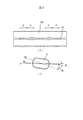
- FIG. 1 is an external view of a rotating electric machine.
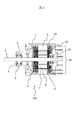
- FIG. 2 is a sectional view of the rotary electric machine.
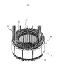
- FIG. 3 is a perspective view of the stator.
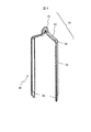
- FIG. 4 is a perspective view showing an example of the segment conductor.
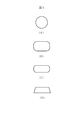
- 5A to 5D are views showing the cross-sectional shape of the segment conductor.
- 6A and 6B are views showing a first example of the method for manufacturing the segment conductor.
- 7A to 7C are a perspective view and a sectional view of the segment conductor.
- FIGS. 8A and 8B are cross-sectional views showing a state in which the segment conductor is inserted into the slot of the stator core.
- FIG. 9 is a figure which shows the 2nd example of the manufacturing method of a segment conductor.
- FIG. 10 is a perspective view showing a segment conductor for a lead wire.
- FIG. 11 is a perspective view showing a deformed segment conductor.
- FIG. 1 is an external view of a rotary electric machine 100 including a segment conductor.
- the rotary electric machine 100 is an electric motor, a generator, or the like mounted on a vehicle or the like and used, for example, a motor used for an electric power steering.
- the rotary electric machine 100 includes a housing 1 and a bracket 2.
- a plurality of coil lead wires 50 extend on the opposite side of the shaft 3.
- a control circuit (not shown) is arranged on the opposite side of the shaft 3.
- FIG. 2 is a sectional view of the rotary electric machine 100.
- An O-ring 6 is provided at the connecting portion between the housing 1 and the bracket 2.
- a front bearing 5 that supports one end of the shaft 3 is fixed to the bracket 2 by a bevel type tomewaw 4.
- the housing 1 is provided with a rear bearing 10 that supports the other end of the shaft 3.
- the shaft 3 is rotatably supported by a front bearing 5 and a rear bearing 10.
- a rotor (movable element) 12 is provided integrally with the shaft 3.
- the rotor (movable element) 12 has an embedded structure in which a permanent magnet 7 is provided in a rotor core 8 or a surface magnet structure.
- the stator 14 is fixed to the inner peripheral surface of the housing 1 by shrink fitting or press fitting.
- the stator 14 inserts a plurality of segment conductors provided with an insulating film such as an enamel film in a plurality of slots (grooves) formed in the stator core 9.
- the segment conductor is composed of at least one straight portion arranged inside the slot and a pair of end portions arranged outside the slot of the stator 14.
- the segment conductors are connected to each other to form a three-phase winding 20, and are drawn out to the coil end side from the plurality of coil lead wires 50.
- FIG. 3 is a perspective view of the stator 14 on which the winding 20 is arranged.
- a plurality of coil lead wires 50 are drawn out from the coil end portion arranged on the upper side in the drawing in the axial direction of the stator core 9.
- a connecting portion 13 of the segment conductor 30 which constitutes the winding 20 is provided on the opposite side of the stator core 9.
- Each segment conductor 30 is inserted into the slot from the upper side in the drawing of the stator core 9 in the axial direction.
- the end of the inserted segment conductor 30 projects from the opposite side of the slot, that is, the lower side in the drawing in the axial direction.
- the ends of the segment conductors 30 protruding from the lower side in the drawing in the axial direction are connected by soldering, Tig welding, laser welding, or the like to form the connecting portion 13.
- FIG. 4 is a perspective view showing an example of the segment conductor 30 inserted into the slot of the stator core 9 in FIG.
- the segment conductor 30 has a substantially left-right symmetric shape centering on the head 31 at the upper part of the drawing. That is, the segment conductor 30 includes a pair of inclined portions 32 on the left and right in the figure, a pair of bent portions 33, and a pair of linear portions 34.
- the head portion 31 is arranged between the pair of inclined portions 32.
- the inclined portion 32 arranged closest to the head portion 31 has an angle of more than 0 degrees and less than 90 degrees with respect to the end surface of the stator core 9.
- the linear portion 34 connected to the inclined portion 32 via the bent portion 33 has a linear shape and is inserted into the slot of the stator core 9.
- the head portion 31, the inclined portion 32, and the bent portion 33 are collectively referred to as a bent portion 35, and a portion joined to another segment conductor 30 formed on the side opposite to the bent portion 35 is a terminal portion. It is called 36. That is, the bent portion 35 is formed between the pair of linear portions 34, and the pair of terminal portions 36 is formed on the opposite side of the pair of linear portions 34 from the bent portion 35.
- FIG. 5 is a diagram showing a cross-sectional shape of the segment conductor 30.
- 5A shows a circular cross section
- FIG. 5B shows a rectangular cross section
- FIG. 5C shows a barrel-shaped cross section
- FIG. 5D shows a trapezoidal cross section.
- FIG. FIG. 5A shows a cross-sectional shape before molding.
- 5(B) to 5(D) show cross-sectional shapes in this embodiment after molding.
- a circular cross section is called a “round cross section”. Although a perfect circle is shown in FIG. 5A, an ellipse is also included in the circular cross section.
- a rectangular cross section is called a “rectangular cross section”. However, the corners may be rounded as shown in FIG. 5B, and the rectangular cross section in this embodiment indicates a shape including two sets of parallel sides. Further, the rectangular cross section can be said to be a shape obtained by collapsing the circular cross section from both the vertical direction and the horizontal direction.
- a cross section composed of a set of parallel sides and two semicircles is called a “barrel cross section”.
- the barrel-shaped cross section can be said to be a shape obtained by squashing a circular cross section from either the vertical direction or the horizontal direction.
- the circular cross section has a shape that is crushed only from the vertical direction in the drawing.
- a cross section having a pair of parallel sides and a hypotenuse that connects them is called a "trapezoid cross section”. Note that although four corners are included in FIG. 5D, the corners may be rounded as in FIGS. 5B and 5C.
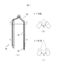
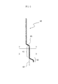
- a press jig 40 is used to press-mold the linear conductor piece 41 having a circular cross section shown in FIG. 5(A).
- the cross section of the press-formed linear conductor piece 41 may be any of the rectangular cross section shown in FIG. 5B, the barrel cross section shown in FIG. 5C, and the trapezoidal cross section shown in FIG. 5D. ..
- this press forming as shown in FIG. 6(B), a twisted portion that partially changes the twist angle in the longitudinal direction of the linear conductor piece 41 is formed.
- the central portion of the linear conductor piece 41 is bent and formed to form the segment conductor 30 having the bent portion 35, the linear portion 34, and the terminal portion 36 shown in FIG. 4.
- the press jig 40 includes a straight portion 34 of the segment conductor 30 which is close to the end portion 36 and a straight portion 34 of the segment conductor 30 which is close to the bent portion 35.
- the molding is performed so that the twist angles are different.
- the angle formed by the side surface b of the linear conductor piece 41 with respect to the center line a extending in the radial direction from the center of the stator 14 through the circumferential center of the slot 15 is defined as the twist angle.
- the angle formed by the side surface by and the center line a is the twist angle ⁇ y.
- the angle formed by the side surface bx and the center line a is the twist angle ⁇ x. In this manner, the straight conductor piece 41 is formed such that the twist angle ⁇ y of the portion Y of the straight conductor piece 41 is larger than the twist angle ⁇ x of the portion X of the straight conductor piece 41.
- FIG. 7 is a perspective view and a sectional view of the segment conductor 30.
- 7A is the same as the perspective view of FIG. 4, but the above-described twisted portion is formed in the straight portion 34 of the segment conductor 30.
- FIG. 7B is a YY cross-sectional view of the segment conductor 30 shown in FIG.
- FIG. 7C is a cross-sectional view of the segment conductor 30 shown in FIG.
- the opening angle ⁇ 1 of the cross section of the straight portion 34 on the side of the terminal portion 36 and the opening angle ⁇ 2 of the coil cross section on the side of the bent portion 35 are different.
- the opening angle ⁇ 2 is larger than the opening angle ⁇ 1, and in the straight portion 34 of the segment conductor 30, the opening angle gradually increases from the end portion 36 side to the bent portion 35 side.
- the segment conductor 30 has a rectangular cross section
- the long side length ⁇ , the short return length ⁇ , the slot width ⁇ , the opening angle ⁇ 1 of the straight section on the terminal side, and the straight section on the bent side If the opening angle is ⁇ 2, the relationship between ⁇ 1 and ⁇ 2 is determined by the following equation (1).
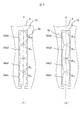
- FIG. 8 is a cross-sectional view showing a state where the segment conductor 30 is inserted into the slot 15 of the stator core 9.
- 8A is a cross section of the straight portion 34 of the segment conductor 30 on the terminal portion 36 side (portion X), and
- FIG. 8B is a bent portion 35 side (portion Y) of the straight portion 34 of the segment conductor 30. The cross section of is shown.
- the linear portions 34x1, 34x2, 34x3, 34x4 of the segment conductor 30 are inserted into the slots 15, but the straight portion 34 of the segment conductor 30 has a twist angle ⁇ x1 ⁇ x4 is small.
- the segment conductors 30 do not make point contact with both sides of the inner wall surface of the slot 15 at the corner portions of the cross-sectional shape of the straight portions 34x1, 34x2, 34x3, 34x4.
- the corner portion may be in point contact with one side of the inner wall surface of the slot 15. This improves the insertability of the segment conductor 30 into the slot 15 when the stator 14 is assembled and manufactured.
- the straight portions 34y1, 34y2, 34y3, 34y4 of the segment conductor 30 are inserted into the slots 15. ⁇ y4 is large. Then, the segment conductor 30 makes point contact with both sides of the inner wall surface of the slot 15 at the corner portions of the cross-sectional shape of the straight portions 34y1, 34y2, 34y3, 34y4.
- the corner portion is not limited to the point contact with both sides of the inner wall surface of the slot 15, but may be the point contact with at least one side of the inner wall surface.
- the contact state is not limited to the point contact, and may be a configuration in which at least the inner wall surface of the slot 15 is in contact. This prevents the segment conductor 30 from being displaced after the segment conductor 30 is inserted into the slot 15.
- the angle formed by bx and by is defined as the twist angle.
- the twist angle is different between the end portion 36 side and the bent portion 35 side of the straight portion 34 of the segment conductor 30.
- the twist angles ⁇ y1 to ⁇ y4 on the bent portion 35 side of the straight portion 34 are larger than the twist angles ⁇ x1 to ⁇ x4 on the terminal portion 36 side of the straight portion 34.
- the twist angle gradually increases from the end portion 36 side to the bent portion 35 side.
- the segment conductor 30 when the segment conductor 30 is inserted into the stator core 9, since the twist angle is relatively small on the side of the terminal portion 36, which is the insertion side of the segment conductor 30, the segment conductor 30 can be easily inserted into the slot 15. Will get better. Further, as the segment conductor 30 is inserted into the slot 15 and approaches the bent portion 35 side, the twist angle changes and comes into contact with the inner wall surface of the slot 15 at the corner portion of the cross-sectional shape of the straight portion 34. Then, the frictional force holds the position of the segment conductor 30.
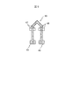
- the end portion 36 side of the segment conductor 30 is fixed to the fixtures 45 and 46.
- the bent portion 35 side of the segment conductor 30 is clamped by the jigs 47 and 48.
- a twisting step of rotating the jigs 47, 48 about the central axis of the segment conductor 30 is performed to generate a twist angle in the straight portion 34 of the segment conductor 30.
- the straight portion 34 of the segment conductor 30 can be formed such that the twist angle gradually increases from the end portion 36 side to the bent portion 35 side.
- the segment conductor 30 shown in FIG. 4 is a hairpin-shaped segment conductor, and the hairpin-shaped segment conductor has been described as an example in the above-mentioned example, but the segment conductor 30 is the segment conductor 60 for the lead wire shown in FIG.
- the plurality of hairpin-shaped segment conductors 30, the lead wire segment conductor 60, and the straight portions 34, 61, 71 of the odd-shaped segment conductor 70 are inserted into the slots 15 of the stator core 9.
- the terminal portions 36, 62, 72 of the respective segment conductors 30, 60, 70 have linear shapes 63, 73 (dotted lines in the figure) extending from the linear portions 34, 61, 71 before being incorporated in the stator core 9.
- the portion Y of the straight line portions 61, 71 close to the bent portions 65, 75 has a larger twist angle than the portion X of the straight line portions 61, 71 close to the terminal portions 62, 72. To be molded.
- the rotating electric machine 100 includes a plurality of segment conductors 30, 60, 70 and a stator core 9 in which a plurality of slots 15 are formed, and the plurality of segment conductors 30, 60, 70 are arranged in the plurality of slots 15
- the mover 12 arranged on the inner peripheral side of the stator 14, and the segment conductors 30, 60, 70 include a pair of linear portions 34, 61 arranged in the slot 15. 71 and the bent portions 35, 65, 75 formed between the pair of linear portions 34, 61, 71, and the bent portions 35, 65, 75 of the pair of linear portions 34, 61, 71 on the opposite side, respectively.
- the twist angle is different between the side of the straight portions 34, 61, 71 closer to the end portions 36, 62, 72 and the side of the straight portions 34, 61, 71 closer to the bent portions 35, 65, 75. This improves the insertability of the segment conductor into the stator slot during assembly and manufacture of the stator, and prevents the segment conductor from being displaced after the segment conductor is inserted.
- the method of manufacturing the rotary electric machine 100 includes a plurality of segment conductors 30, 60, 70 and a stator core 9 having a plurality of slots 15 formed therein, and a plurality of segment conductors 30, 60, 70.
- the stator 14 arranged in the slot 15 of the stator and the mover 12 arranged on the inner peripheral side of the stator 14 are provided, and the segment conductors 30, 60, and 70 are connected to the slot 15 when the stator 14 is manufactured.
- Segment conductors 30, which have terminal portions 36, 62, 72 inserted in the slots 15, bent portions 35, 65, 75 not inserted in the slots 15, and straight portions 34, 61, 71 arranged in the slots 15.
- the twist angle formed by the center line extending in the radial direction from the center of the stator 14 and the side surfaces of the linear portions 34, 61 and 71 of the segment conductors 30, 60 and 70 is The segment conductors 30, 60, 70 are arranged so that the side portions of the linear portions 34, 61, 71 close to the terminal portions 36, 62, 72 and the side portions of the linear portions 34, 61, 71 close to the bent portions 35, 65, 75 are different. And a second step of inserting the twisted segment conductors 30, 60, 70 into the slots 15 from the end portions 36, 62, 72. This improves the insertability of the segment conductor into the stator slot during assembly and manufacture of the stator, and prevents the segment conductor from being displaced after the segment conductor is inserted.
Landscapes
- Engineering & Computer Science (AREA)
- Power Engineering (AREA)
- Manufacturing & Machinery (AREA)
- Windings For Motors And Generators (AREA)
- Manufacture Of Motors, Generators (AREA)
Abstract
複数のセグメント導体と、複数のスロットが形成された鉄心とを有し、前記複数のセグメント導体を前記複数のスロットに配置した固定子と、前記固定子の内周側に配置される可動子とを備え、前記セグメント導体は、前記スロット内に配置される一対の直線部と、前記一対の直線部の間に形成される折り曲げ部と、前記一対の直線部の前記折り曲げ部とは反対側にそれぞれ形成される一対の端末部と、を有し、前記固定子の中心から径方向に延びる中心線と前記セグメント導体の前記直線部の側面とのなすねじれ角度は、前記直線部の前記端末部に近い側と前記直線部の前記折り曲げ部に近い側とで異なる回転電機。
Description
本発明は回転電機および回転電機の製造方法に関する。
車両等に搭載されて使用される電動機や発電機などの回転電機は、回転可能に設けられた回転子と、この回転子と径方向に対向して配置された固定子とを備えている。固定子は、周方向に配列された複数のスロットを有する固定子鉄心と、この固定子鉄心の複数のスロットに嵌装されたセグメント導体とを備えている。
特許文献1には、周方向に複数のスロットを有する固定子鉄心と、スロットに嵌装されたセグメント導体とを円環状に備える回転電機の固定子が記載されている。そして、各スロットに挿入されたセグメント導体の端部同士が接合されて固定子巻線を構成する。
特許文献1に記載の固定子は、固定子の組立製造時におけるセグメント導体の固定子スロットへの挿入性が損なわれ、セグメント導体の挿入後にセグメント導体の位置ずれが生じる問題があった。
本発明の第1の態様による回転電機は、複数のセグメント導体と、複数のスロットが形成された鉄心とを有し、前記複数のセグメント導体を前記複数のスロットに配置した固定子と、前記固定子の内周側に配置される可動子とを備え、前記セグメント導体は、前記スロット内に配置される一対の直線部と、前記一対の直線部の間に形成される折り曲げ部と、前記一対の直線部の前記折り曲げ部とは反対側にそれぞれ形成される一対の端末部と、を有し、前記固定子の中心から径方向に延びる中心線と前記セグメント導体の前記直線部の側面とのなすねじれ角度は、前記直線部の前記端末部に近い側と前記直線部の前記折り曲げ部に近い側とで異なるのが好ましい。
本発明の第2の態様による回転電機の製造方法は、複数のセグメント導体と、複数のスロットが形成された鉄心とを有し、前記複数のセグメント導体を前記複数のスロットに配置した固定子と、前記固定子の内周側に配置される可動子とを備える回転電機の製造方法であって、前記セグメント導体は、前記固定子の製造時において、前記スロットへ先に挿入される端末部と、前記スロットへ挿入されない折り曲げ部と、前記スロット内に配置される直線部とを有し、前記セグメント導体が前記スロットへ挿入されたときに、前記固定子の中心から径方向に延びる中心線と前記セグメント導体の前記直線部の側面とのなすねじれ角度が、前記直線部の前記端末部に近い側と前記直線部の前記折り曲げ部に近い側とで異なるように、前記セグメント導体にねじれ部を形成する第一の工程と、前記ねじれ部が形成された前記セグメント導体を前記端末部から前記スロットへ挿入する第二の工程とを備えるのが好ましい。
本発明の第2の態様による回転電機の製造方法は、複数のセグメント導体と、複数のスロットが形成された鉄心とを有し、前記複数のセグメント導体を前記複数のスロットに配置した固定子と、前記固定子の内周側に配置される可動子とを備える回転電機の製造方法であって、前記セグメント導体は、前記固定子の製造時において、前記スロットへ先に挿入される端末部と、前記スロットへ挿入されない折り曲げ部と、前記スロット内に配置される直線部とを有し、前記セグメント導体が前記スロットへ挿入されたときに、前記固定子の中心から径方向に延びる中心線と前記セグメント導体の前記直線部の側面とのなすねじれ角度が、前記直線部の前記端末部に近い側と前記直線部の前記折り曲げ部に近い側とで異なるように、前記セグメント導体にねじれ部を形成する第一の工程と、前記ねじれ部が形成された前記セグメント導体を前記端末部から前記スロットへ挿入する第二の工程とを備えるのが好ましい。
本発明によれば、固定子の組立製造時におけるセグメント導体の固定子スロットへの挿入性が向上し、セグメント導体の挿入後にセグメント導体の位置ずれを防止できる。
上記した以外の課題、構成および効果は、以下の発明を実施するための形態の説明により明らかにされる。
上記した以外の課題、構成および効果は、以下の発明を実施するための形態の説明により明らかにされる。
以下、図面を参照して本発明の実施形態を説明する。以下の記載および図面は、本発明を説明するための例示であって、説明の明確化のため、適宜、省略および簡略化がなされている。本発明は、他の種々の形態でも実施する事が可能である。特に限定しない限り、各構成要素は単数でも複数でも構わない。
図面において示す各構成要素の位置、大きさ、形状、範囲などは、発明の理解を容易にするため、実際の位置、大きさ、形状、範囲などを表していない場合がある。このため、本発明は、必ずしも、図面に開示された位置、大きさ、形状、範囲などに限定されない。
以下、本実施形態について図面を参照して説明する。
図1は、セグメント導体を内蔵する回転電機100の外観図である。回転電機100は、車両等に搭載されて使用される電動機や発電機などであり、例えば、電動パワーステアリングに用いられるモータである。回転電機100は、ハウジング1と、ブラケット2とを備える。ブラケット2からは出力軸であるシャフト3が突出している。シャフト3の反対側に複数のコイル口出し線50が延出している。また、シャフト3の反対側には制御回路(不図示)が配置される。
図1は、セグメント導体を内蔵する回転電機100の外観図である。回転電機100は、車両等に搭載されて使用される電動機や発電機などであり、例えば、電動パワーステアリングに用いられるモータである。回転電機100は、ハウジング1と、ブラケット2とを備える。ブラケット2からは出力軸であるシャフト3が突出している。シャフト3の反対側に複数のコイル口出し線50が延出している。また、シャフト3の反対側には制御回路(不図示)が配置される。
図2は、回転電機100の断面図である。ハウジング1とブラケット2との間にはその接続部にOリング6が設けられている。ブラケット2には、シャフト3の一端側を支持するフロントベアリング5がベベル型トメワ4で固定されている。一方、ハウジング1には、シャフト3の他端側を支持するリアベアリング10が設けられている。シャフト3は、フロントベアリング5およびリアベアリング10により回転可能に支持されている。固定子14の内周側には、シャフト3と一体化して回転子(可動子)12が設けられる。回転子(可動子)12は、回転子鉄心8の中に永久磁石7が設けられた埋め込み構造や表面磁石構造となっている。
ハウジング1の内周面に固定子14が焼き嵌めや圧入により固定される。固定子14は、固定子鉄心9に形成された複数のスロット(溝)内にエナメル皮膜などの絶縁皮膜が付与されたセグメント導体を複数挿入する。セグメント導体は、スロット内に配置される少なくとも一つの直線部と、固定子14のスロット外に配置される一対の端末部よりなる。セグメント導体は、互いに接続されて3相の巻線20を形成し、複数のコイル口出し線50よりコイルエンド部側に引き出される。
図3は、巻線20が配置された固定子14の斜視図である。固定子鉄心9の軸方向で図示上側に配置されたコイルエンド部からは、複数のコイル口出し線50が引き出されている。固定子鉄心9の反対側には巻線20を構成するセグメント導体30の接続部13が設けられている。各セグメント導体30は、固定子鉄心9の軸方向の図示上側からスロットに挿入される。挿入されたセグメント導体30の端部はスロットの反対側、すなわち軸方向の図示下側から突出している。軸方向の図示下側から突出したセグメント導体30の端部は半田、Tig溶接およびレーザー溶接等により接続され接続部13を構成する。
図4は、図3において固定子鉄心9のスロットに挿入されるセグメント導体30の一例を示す斜視図である。セグメント導体30は、図示上部の頭部31を中心とした略左右対称な形状を有する。すなわち、セグメント導体30は、図示左右1組の傾斜部32と、1組の屈曲部33と、1組の直線部34とを備える。頭部31は1組の傾斜部32の間に配される。頭部31に最も近く配置される傾斜部32は、固定子鉄心9の端面に対して0度より大きく90度未満の角度を有する。屈曲部33を介して傾斜部32に接続される直線部34は、直線の形状を有し、固定子鉄心9のスロットに挿入される。ここで、頭部31、傾斜部32、屈曲部33を総称して折り曲げ部35と呼称し、折り曲げ部35とは反対側にそれぞれ形成される他のセグメント導体30と接合される部分を端末部36と呼称する。すなわち、折り曲げ部35は一対の直線部34の間に形成されており、一対の直線部34の折り曲げ部35と反対側には、一対の端末部36がそれぞれ形成されている。
図5は、セグメント導体30の断面形状を示す図である。図5(A)は、丸断面を示す図、図5(B)は、矩形断面を示す図、図5(C)は、たる状断面を示す図、図5(D)は、台形断面を示す図である。図5(A)は、成形する前の断面形状を示す。図5(B)~図5(D)は、成形した後の本実施形態における断面形状を示す。
図5(A)に示すように、円形の断面を「丸断面」と呼ぶ。なお、図5(A)では真円を示しているが、楕円も丸断面に含む。図5(B)に示すように、矩形の断面を「矩形断面」と呼ぶ。ただし、図5(B)に示すように角が丸くてもよく、本実施形態における矩形断面は、断面が平行な2組の辺を含む形状を指す。また、矩形断面は、円形断面を上下方向と左右方向の両方からつぶした形状とも言える。
図5(C)に示すように、1組の平行な辺と2つの半円の組み合わせからなる断面を「たる状断面」と呼ぶ。たる状断面は、円形断面を上下方向および左右方向のいずれか一方からつぶした形状とも言える。図5(C)では円形断面を図示上下方向のみからつぶした形状である。図5(D)に示すように、1組の平行な辺とそれらを接続する斜辺を有する断面を「台形断面」と呼ぶ。ただし図5(D)では4隅に角を有するが、図5(B)や図5(C)のように角が丸くてもよい。
次に、セグメント導体30の製造方法の第一の例について図6を参照して説明する。
図6(A)に示すようにプレス冶具40を用いて、図5(A)に示す丸断面の直線状導体片41をプレス成形する。プレス成形された直線状導体片41の断面は、図5(B)に示す矩形断面、図5(C)に示すたる状断面、図5(D)に示す台形断面のいずれかであればよい。このプレス成形において、図6(B)に示すように直線状導体片41の長手方向において部分的にねじれ角度を変えるねじれ部が形成される。続いて、直線状導体片41の中央部を曲げ成形して、図4に示す、折り曲げ部35、直線部34、端末部36を有するセグメント導体30を形成する。
図6(A)に示すようにプレス冶具40を用いて、図5(A)に示す丸断面の直線状導体片41をプレス成形する。プレス成形された直線状導体片41の断面は、図5(B)に示す矩形断面、図5(C)に示すたる状断面、図5(D)に示す台形断面のいずれかであればよい。このプレス成形において、図6(B)に示すように直線状導体片41の長手方向において部分的にねじれ角度を変えるねじれ部が形成される。続いて、直線状導体片41の中央部を曲げ成形して、図4に示す、折り曲げ部35、直線部34、端末部36を有するセグメント導体30を形成する。
プレス成形におけるねじれ部の形成を具体的に説明する。図6(A)に示すように、プレス冶具40は、セグメント導体30の直線部34であって端末部36に近い部分Xとセグメント導体30の直線部34であって折り曲げ部35に近い部分Yにおいて、それぞれねじれ角度が異なるように成形する。
ここで、後述するように固定子14の中心からスロット15の周方向中心を通って径方向に延びる中心線aに対する直線状導体片41の側面bのなす角度をねじれ角度と定義する。図6(B)に示すように、直線状導体片41の部分Yを点線で示すとその側面byと中心線aのなす角度はねじれ角度φyである。一方、直線状導体片41の部分Xを実線で示すとその側面bxと中心線aのなす角度はねじれ角度φxである。このように、直線状導体片41は、直線状導体片41の部分Yのねじれ角度φyは、直線状導体片41の部分Xのねじれ角度φxより大きくなるように成形される。
図7は、セグメント導体30の斜視図および断面図である。図7(A)は、図4の斜視図と同様であるが、セグメント導体30の直線部34において上述したねじれ部を形成している。図7(B)は、図7(A)に示すセグメント導体30のY-Y断面図である。図7(C)は、図7(A)に示すセグメント導体30のX-X断面図である。
図7(B)、図7(C)に示すように、セグメント導体30は、直線部34において端末部36側の断面の開き角θ1と折り曲げ部35側のコイル断面の開き角θ2が異なる。開き角θ2は開き角θ1より大きく、また、セグメント導体30の直線部34において端末部36側から折り曲げ部35側に行くに従って徐々に開き角が大きくなる。
例えば、セグメント導体30が矩形断面の場合は長辺の長さα、短返の長さβ、スロットの幅γ、端末部側の直線部断面の開き角θ1、折り曲げ部側の直線部断面の開き角θ2とすると、θ1とθ2の関係は次式(1)で決定される。

図8は、セグメント導体30を固定子鉄心9のスロット15に挿入した状態の断面図である。図8(A)は、セグメント導体30の直線部34における端末部36側(部分X)の断面を、図8(B)は、セグメント導体30の直線部34における折り曲げ部35側(部分Y)の断面を示す。
図8(A)に示すようにセグメント導体30の直線部34x1、34x2、34x3、34x4が、スロット15に挿入されているが、セグメント導体30の直線部34における端末部36側は、ねじれ角度φx1~φx4が小さい。セグメント導体30は、直線部34x1、34x2、34x3、34x4の断面形状の角部分においてスロット15の内壁面の両側と点接触しない。なお、角部分がスロット15の内壁面の片側と点接触する構成であってもよい。これにより、固定子14の組立製造時におけるセグメント導体30のスロット15への挿入性が向上する。
図8(B)に示すようにセグメント導体30の直線部34y1、34y2、34y3、34y4が、スロット15に挿入されているが、セグメント導体30の直線部34における折り曲げ部35側は、ねじれ角度φy1~φy4が大きい。そして、セグメント導体30は、直線部34y1、34y2、34y3、34y4の断面形状の角部分においてスロット15の内壁面の両側と点接触する。なお、角部分がスロット15の内壁面の両側と点接触する構成に限らず、内壁面の少なくとも片側において点接触する構成であってもよい。また、接触状態は点接触に限らず、少なくともスロット15の内壁面と接触する構成であればよい。これにより、セグメント導体30をスロット15に挿入した後にセグメント導体30の位置ずれを防止できる。
このように、固定子14の軸方向と直交するセグメント導体30の断面において、固定子14の中心からスロット15の周方向中心を通って径方向に延びる中心線aに対する直線状導体片41の側面bx、byのなす角度をねじれ角度と定義する。ねじれ角度は、セグメント導体30の直線部34の端末部36側と折り曲げ部35側で異なる。直線部34の折り曲げ部35側のねじれ角度φy1~φy4は、直線部34の端末部36側のねじれ角度φx1~φx4より大きい。また、セグメント導体30の直線部34において端末部36側から折り曲げ部35側に行くに従って徐々にねじれ角度が大きくなる。
これにより、セグメント導体30を固定子鉄心9に挿入する場合に、セグメント導体30の挿入側である端末部36側はねじれ角度が比較的小さく揃っているので、セグメント導体30のスロット15に対する挿入性が良くなる。さらに、セグメント導体30をスロット15に挿入していき、折り曲げ部35側に近づくと、ねじれ角度が変化していき、直線部34の断面形状の角部分においてスロット15の内壁面と接触する。そして、その摩擦力によりセグメント導体30の位置が保持される。
次に、セグメント導体30の製造方法の第二の例について図9を参照して説明する。
図9に示すように、セグメント導体30の端末部36側を固定具45、46に固定する。次に、セグメント導体30の折り曲げ部35側を冶具47、48で挟持する。そして、セグメント導体30の中心軸を中心に冶具47、48を回動するねじり工程を行い、セグメント導体30の直線部34にねじれ角度を生じさせる。これにより、セグメント導体30の直線部34において、端末部36側から折り曲げ部35側に行くに従って徐々にねじれ角度が大きくなるように成形することができる。
図9に示すように、セグメント導体30の端末部36側を固定具45、46に固定する。次に、セグメント導体30の折り曲げ部35側を冶具47、48で挟持する。そして、セグメント導体30の中心軸を中心に冶具47、48を回動するねじり工程を行い、セグメント導体30の直線部34にねじれ角度を生じさせる。これにより、セグメント導体30の直線部34において、端末部36側から折り曲げ部35側に行くに従って徐々にねじれ角度が大きくなるように成形することができる。
なお、図4に示したセグメント導体30はヘアピン形セグメント導体であり、上述の例ではこのヘアピン形セグメント導体を例に説明したが、セグメント導体30は図10に示す口出し線用セグメント導体60、図11に示す異形セグメント導体70であってもよい。
固定子鉄心9のスロット15に、複数のヘアピン形セグメント導体30、口出し線用セグメント導体60、異形セグメント導体70の直線部34、61、71が挿入される。各セグメント導体30、60、70の端末部36、62、72は、固定子鉄心9に組み込む前は、直線部34、61、71から延びる直線形状63、73(図示点線)である。各セグメント導体30、60、70を固定子鉄心9に組み込んだ後は、固定子鉄心9の軸方向端面から突出した部位を曲げ成形(図示実線)する。
ここで、上述したセグメント導体30と同様に、折り曲げ部65、75に近い直線部61、71の部分Yは、端末部62、72に近い直線部61、71の部分Xよりもねじれ角度が大きくなるように成形される。
以上説明した実施形態によれば、次の作用効果が得られる。
(1)回転電機100は、複数のセグメント導体30、60、70と、複数のスロット15が形成された固定子鉄心9とを有し、複数のセグメント導体30、60、70を複数のスロット15に配置した固定子14と、固定子14の内周側に配置される可動子12とを備え、セグメント導体30、60、70は、スロット15内に配置される一対の直線部34、61、71と、一対の直線部34、61、71の間に形成される折り曲げ部35、65、75と、一対の直線部34、61、71の折り曲げ部35、65、75とは反対側にそれぞれ形成される一対の端末部36、62、72と、を有し、固定子14の中心から径方向に延びる中心線とセグメント導体30、60、70の直線部34、61、71の側面とのなすねじれ角度は、直線部34、61、71の端末部36、62、72に近い側と直線部34、61、71の折り曲げ部35、65、75に近い側とで異なる。これにより、固定子の組立製造時におけるセグメント導体の固定子スロットへの挿入性が向上し、セグメント導体の挿入後にセグメント導体の位置ずれを防止できる。
(1)回転電機100は、複数のセグメント導体30、60、70と、複数のスロット15が形成された固定子鉄心9とを有し、複数のセグメント導体30、60、70を複数のスロット15に配置した固定子14と、固定子14の内周側に配置される可動子12とを備え、セグメント導体30、60、70は、スロット15内に配置される一対の直線部34、61、71と、一対の直線部34、61、71の間に形成される折り曲げ部35、65、75と、一対の直線部34、61、71の折り曲げ部35、65、75とは反対側にそれぞれ形成される一対の端末部36、62、72と、を有し、固定子14の中心から径方向に延びる中心線とセグメント導体30、60、70の直線部34、61、71の側面とのなすねじれ角度は、直線部34、61、71の端末部36、62、72に近い側と直線部34、61、71の折り曲げ部35、65、75に近い側とで異なる。これにより、固定子の組立製造時におけるセグメント導体の固定子スロットへの挿入性が向上し、セグメント導体の挿入後にセグメント導体の位置ずれを防止できる。
(2)回転電機100の製造方法は、複数のセグメント導体30、60、70と、複数のスロット15が形成された固定子鉄心9とを有し、複数のセグメント導体30、60、70を複数のスロット15に配置した固定子14と、固定子14の内周側に配置される可動子12とを備え、セグメント導体30、60、70は、固定子14の製造時において、スロット15へ先に挿入される端末部36、62、72と、スロット15へ挿入されない折り曲げ部35、65、75と、スロット15内に配置される直線部34、61、71とを有し、セグメント導体30、60、70がスロット15へ挿入されたときに、固定子14の中心から径方向に延びる中心線とセグメント導体30、60、70の直線部34、61、71の側面とのなすねじれ角度が、直線部34、61、71の端末部36、62、72に近い側と直線部34、61、71の折り曲げ部35、65、75に近い側とで異なるように、セグメント導体30、60、70にねじれ部を形成する第一の工程と、ねじれ部が形成されたセグメント導体30、60、70を端末部36、62、72からスロット15へ挿入する第二の工程とを備える。これにより、固定子の組立製造時におけるセグメント導体の固定子スロットへの挿入性が向上し、セグメント導体の挿入後にセグメント導体の位置ずれを防止できる。
本発明は、上記の実施形態に限定されるものではなく、本発明の特徴を損なわない限り、本発明の技術思想の範囲内で考えられるその他の形態についても、本発明の範囲内に含まれる。
次の優先権基礎出願の開示内容は引用文としてここに組み込まれる。
日本国特許出願2019-19174(2019年2月5日出願)
日本国特許出願2019-19174(2019年2月5日出願)
1 ハウジング
2 ブラケット
3 シャフト
4 トメワ
5、10 ベアリング
6 Oリング
7 永久磁石
8 回転子鉄心
9 固定子鉄心
12 回転子(可動子)
13 接続部
14 固定子
15 スロット
20 巻線
30、60、70 セグメント導体
31 頭部
32 傾斜部
33 屈曲部
34、61、71 直線部
35、65、75 折り曲げ部
36、62、72 端末部
40 プレス冶具
41 直線状導体片
45、46 固定具
47、48 冶具
50 コイル口出し線
100 回転電機
2 ブラケット
3 シャフト
4 トメワ
5、10 ベアリング
6 Oリング
7 永久磁石
8 回転子鉄心
9 固定子鉄心
12 回転子(可動子)
13 接続部
14 固定子
15 スロット
20 巻線
30、60、70 セグメント導体
31 頭部
32 傾斜部
33 屈曲部
34、61、71 直線部
35、65、75 折り曲げ部
36、62、72 端末部
40 プレス冶具
41 直線状導体片
45、46 固定具
47、48 冶具
50 コイル口出し線
100 回転電機
Claims (8)
- 複数のセグメント導体と、複数のスロットが形成された鉄心とを有し、前記複数のセグメント導体を前記複数のスロットに配置した固定子と、
前記固定子の内周側に配置される可動子とを備え、
前記セグメント導体は、前記スロット内に配置される一対の直線部と、前記一対の直線部の間に形成される折り曲げ部と、前記一対の直線部の前記折り曲げ部とは反対側にそれぞれ形成される一対の端末部と、を有し、
前記固定子の中心から径方向に延びる中心線と前記セグメント導体の前記直線部の側面とのなすねじれ角度は、前記直線部の前記端末部に近い側と前記直線部の前記折り曲げ部に近い側とで異なる回転電機。 - 請求項1に記載の回転電機において、
前記ねじれ角度は、前記直線部の前記端末部に近い側が前記直線部の前記折り曲げ部に近い側より小さく、
前記セグメント導体は、前記直線部の前記折り曲げ部に近い側が前記スロットの内壁面と接触している回転電機。 - 請求項2に記載の回転電機において、
前記セグメント導体は、前記直線部の前記折り曲げ部に近い側が前記スロットの内壁面の両側と接触している回転電機。 - 請求項1または請求項2に記載の回転電機において、
前記セグメント導体の前記直線部は、矩形、たる状、台形のいずれかの断面形状を有する回転電機。 - 複数のセグメント導体と、複数のスロットが形成された鉄心とを有し、前記複数のセグメント導体を前記複数のスロットに配置した固定子と、
前記固定子の内周側に配置される可動子とを備える回転電機の製造方法であって、
前記セグメント導体は、前記固定子の製造時において、前記スロットへ先に挿入される端末部と、前記スロットへ挿入されない折り曲げ部と、前記スロット内に配置される直線部とを有し、
前記セグメント導体が前記スロットへ挿入されたときに、前記固定子の中心から径方向に延びる中心線と前記セグメント導体の前記直線部の側面とのなすねじれ角度が、前記直線部の前記端末部に近い側と前記直線部の前記折り曲げ部に近い側とで異なるように、前記セグメント導体にねじれ部を形成する第一の工程と、
前記ねじれ部が形成された前記セグメント導体を前記端末部から前記スロットへ挿入する第二の工程とを備える回転電機の製造方法。 - 請求項5に記載の回転電機の製造方法において、
前記第一の工程は、前記セグメント導体を押し潰して前記ねじれ部を形成するプレス工程である回転電機の製造方法。 - 請求項5に記載の回転電機の製造方法において、
前記第一の工程は、前記セグメント導体をその中心軸を中心に回動して前記ねじれ部を形成するねじり工程である回転電機の製造方法。 - 請求項6または請求項7に記載の回転電機の製造方法において、
前記第一の工程では、前記ねじれ角度が、前記直線部の前記端末部に近い側が前記直線部の前記折り曲げ部に近い側より小さくなるように、前記セグメント導体に前記ねじれ部を形成する回転電機の製造方法。
Applications Claiming Priority (2)
| Application Number | Priority Date | Filing Date | Title |
|---|---|---|---|
| JP2019-019174 | 2019-02-05 | ||
| JP2019019174A JP7125360B2 (ja) | 2019-02-05 | 2019-02-05 | 回転電機および回転電機の製造方法 |
Publications (1)
| Publication Number | Publication Date |
|---|---|
| WO2020162337A1 true WO2020162337A1 (ja) | 2020-08-13 |
Family
ID=71947470
Family Applications (1)
| Application Number | Title | Priority Date | Filing Date |
|---|---|---|---|
| PCT/JP2020/003584 Ceased WO2020162337A1 (ja) | 2019-02-05 | 2020-01-31 | 回転電機および回転電機の製造方法 |
Country Status (2)
| Country | Link |
|---|---|
| JP (1) | JP7125360B2 (ja) |
| WO (1) | WO2020162337A1 (ja) |
Cited By (1)
| Publication number | Priority date | Publication date | Assignee | Title |
|---|---|---|---|---|
| WO2024046522A1 (de) * | 2022-08-29 | 2024-03-07 | Schaeffler Technologies AG & Co. KG | Stator und kit-of-parts |
Families Citing this family (2)
| Publication number | Priority date | Publication date | Assignee | Title |
|---|---|---|---|---|
| DE102021133029B4 (de) * | 2021-12-14 | 2024-01-04 | Schaeffler Technologies AG & Co. KG | Stator |
| DE102022113930B4 (de) | 2022-06-02 | 2026-07-16 | Schaeffler Technologies AG & Co. KG | Stator für eine elektrische Maschine |
Citations (2)
| Publication number | Priority date | Publication date | Assignee | Title |
|---|---|---|---|---|
| JP2003219588A (ja) * | 2002-01-18 | 2003-07-31 | Denso Corp | 車両用回転電機の固定子及びその製造方法 |
| JP2018148668A (ja) * | 2017-03-03 | 2018-09-20 | アイシン・エィ・ダブリュ株式会社 | 回転電機用の導体線接合方法及び回転電機用導体 |
Family Cites Families (2)
| Publication number | Priority date | Publication date | Assignee | Title |
|---|---|---|---|---|
| JP2007110899A (ja) | 2007-01-31 | 2007-04-26 | Denso Corp | 車両用交流発電機 |
| JP5849802B2 (ja) | 2012-03-21 | 2016-02-03 | 株式会社デンソー | 回転電機及びセグメントの製造方法 |
-
2019
- 2019-02-05 JP JP2019019174A patent/JP7125360B2/ja not_active Expired - Fee Related
-
2020
- 2020-01-31 WO PCT/JP2020/003584 patent/WO2020162337A1/ja not_active Ceased
Patent Citations (2)
| Publication number | Priority date | Publication date | Assignee | Title |
|---|---|---|---|---|
| JP2003219588A (ja) * | 2002-01-18 | 2003-07-31 | Denso Corp | 車両用回転電機の固定子及びその製造方法 |
| JP2018148668A (ja) * | 2017-03-03 | 2018-09-20 | アイシン・エィ・ダブリュ株式会社 | 回転電機用の導体線接合方法及び回転電機用導体 |
Cited By (1)
| Publication number | Priority date | Publication date | Assignee | Title |
|---|---|---|---|---|
| WO2024046522A1 (de) * | 2022-08-29 | 2024-03-07 | Schaeffler Technologies AG & Co. KG | Stator und kit-of-parts |
Also Published As
| Publication number | Publication date |
|---|---|
| JP7125360B2 (ja) | 2022-08-24 |
| JP2020127316A (ja) | 2020-08-20 |
Similar Documents
| Publication | Publication Date | Title |
|---|---|---|
| CN101728888B (zh) | 用于电机线圈的配线部件 | |
| JPWO2020017133A1 (ja) | 分布巻ラジアルギャップ型回転電機及びその固定子 | |
| JP4270307B2 (ja) | 渡り線モジュール | |
| EP1641107B1 (en) | Stepping motor and method of manufacturing the same | |
| WO2019039518A1 (ja) | 分割コア連結体および電機子の製造方法 | |
| KR20030084552A (ko) | 회전전기 및 그의 제조방법 | |
| WO2020013078A1 (ja) | モータ及び電動パワーステアリング装置 | |
| JP7125360B2 (ja) | 回転電機および回転電機の製造方法 | |
| US11539260B2 (en) | Stator and motor | |
| JP5282153B1 (ja) | レゾルバのステータ及びステータ組立体の製造方法 | |
| JP2021057999A (ja) | ステータおよびモータ | |
| JP6620311B2 (ja) | 電動機及びこれを備えた送風機 | |
| JP4297929B2 (ja) | モータ及びモータの製造方法 | |
| WO2019065450A1 (ja) | モータ、及びモータの製造方法 | |
| WO2020080548A1 (ja) | モータ | |
| US12348096B2 (en) | Coil having segment conductors welded with a welded metal portion | |
| JP6111885B2 (ja) | 導線成形装置、ステータ、及び、そのステータを用いたモータ | |
| JP2019068647A (ja) | 回転電機 | |
| WO2022264494A1 (ja) | 回転電機および回転電機の製造方法 | |
| JP5067416B2 (ja) | 回転電機 | |
| JP2004096847A (ja) | 車両用交流発電機の回転子 | |
| JPS63194541A (ja) | 整流子付小形電動機の電機子 | |
| JP7569636B2 (ja) | 回転電機、および回転電機の製造方法 | |
| JP2020141530A (ja) | 固定子、及び回転電機 | |
| JP7254675B2 (ja) | ブラシレスモータ及びステータ製造方法 |
Legal Events
| Date | Code | Title | Description |
|---|---|---|---|
| 121 | Ep: the epo has been informed by wipo that ep was designated in this application |
Ref document number: 20752167 Country of ref document: EP Kind code of ref document: A1 |
|
| NENP | Non-entry into the national phase |
Ref country code: DE |
|
| 122 | Ep: pct application non-entry in european phase |
Ref document number: 20752167 Country of ref document: EP Kind code of ref document: A1 |