WO2020161964A1 - 起伏ゲート式防波堤 - Google Patents
起伏ゲート式防波堤 Download PDFInfo
- Publication number
- WO2020161964A1 WO2020161964A1 PCT/JP2019/040843 JP2019040843W WO2020161964A1 WO 2020161964 A1 WO2020161964 A1 WO 2020161964A1 JP 2019040843 W JP2019040843 W JP 2019040843W WO 2020161964 A1 WO2020161964 A1 WO 2020161964A1
- Authority
- WO
- WIPO (PCT)
- Prior art keywords
- water
- door body
- storage chamber
- water storage
- gate type
- Prior art date
- Legal status (The legal status is an assumption and is not a legal conclusion. Google has not performed a legal analysis and makes no representation as to the accuracy of the status listed.)
- Ceased
Links
Images




Classifications
-
- E—FIXED CONSTRUCTIONS
- E02—HYDRAULIC ENGINEERING; FOUNDATIONS; SOIL SHIFTING
- E02B—HYDRAULIC ENGINEERING
- E02B3/00—Engineering works in connection with control or use of streams, rivers, coasts, or other marine sites; Sealings or joints for engineering works in general
- E02B3/04—Structures or apparatus for, or methods of, protecting banks, coasts, or harbours
- E02B3/06—Moles; Piers; Quays; Quay walls; Groynes; Breakwaters ; Wave dissipating walls; Quay equipment
-
- E—FIXED CONSTRUCTIONS
- E02—HYDRAULIC ENGINEERING; FOUNDATIONS; SOIL SHIFTING
- E02B—HYDRAULIC ENGINEERING
- E02B7/00—Barrages or weirs; Layout, construction, methods of, or devices for, making same
- E02B7/20—Movable barrages; Lock or dry-dock gates
-
- E—FIXED CONSTRUCTIONS
- E02—HYDRAULIC ENGINEERING; FOUNDATIONS; SOIL SHIFTING
- E02B—HYDRAULIC ENGINEERING
- E02B7/00—Barrages or weirs; Layout, construction, methods of, or devices for, making same
- E02B7/20—Movable barrages; Lock or dry-dock gates
- E02B7/40—Swinging or turning gates
-
- Y—GENERAL TAGGING OF NEW TECHNOLOGICAL DEVELOPMENTS; GENERAL TAGGING OF CROSS-SECTIONAL TECHNOLOGIES SPANNING OVER SEVERAL SECTIONS OF THE IPC; TECHNICAL SUBJECTS COVERED BY FORMER USPC CROSS-REFERENCE ART COLLECTIONS [XRACs] AND DIGESTS
- Y02—TECHNOLOGIES OR APPLICATIONS FOR MITIGATION OR ADAPTATION AGAINST CLIMATE CHANGE
- Y02A—TECHNOLOGIES FOR ADAPTATION TO CLIMATE CHANGE
- Y02A10/00—TECHNOLOGIES FOR ADAPTATION TO CLIMATE CHANGE at coastal zones; at river basins
- Y02A10/11—Hard structures, e.g. dams, dykes or breakwaters
Definitions
- This application relates to an undulating gate type breakwater.
- An undulating gate type breakwater installed in a port as a measure against tsunamis and storm surges is disclosed in Patent Document 1, for example.
- This type of breakwater includes a door body that stands up (floats) by buoyancy, and a storage unit that stores the door body in a lying state.
- a gap is provided between the collapsed door body and the storage unit to such an extent that the operation of the door body is not hindered.
- the technique disclosed in the present application has been made in view of such circumstances, and an object thereof is to speed up the standing start operation (floating start operation) of the door body while reducing the gap between the door body and the storage unit.
- the purpose is to provide an undulating gate type breakwater that can be used.
- the undulating gate type breakwater of the present application includes a door body, a storage unit, and a water supply mechanism.
- the door body is provided in the water, and is erected from the fallen state by buoyancy so as to rotate around a rotation axis on the base end side.
- the storage section is provided below the door body in the lying state, and the door body is stored therein.
- the water supply mechanism has a water storage chamber, and supplies the water in the water storage chamber to the internal space of the storage unit as the door body starts to stand up.
- the undulating gate type breakwater of the present application it is possible to speed up the rising start operation (floating start operation) of the door body while reducing the gap between the door body and the storage unit.
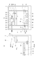
- FIG. 1 is a plan view showing a schematic configuration of an undulating gate type breakwater according to the first embodiment.
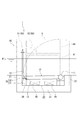
- FIG. 2 is a view showing the undulating gate type breakwater according to the first embodiment as viewed from the side.
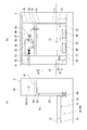
- FIG. 3 shows a schematic configuration of the water supply mechanism according to the first embodiment, where (a) is a view as seen from the outside of the port and (b) is a view as seen from the side.
- FIG. 4 is a diagram for explaining the downward swinging motion of the door body.
- FIG. 5 is a figure for demonstrating the upward motion of a door body.
- FIG. 6 shows a schematic configuration of the water supply mechanism according to the first embodiment, where (a) is a view as seen from the outside of the port and (b) is a view as seen from the side.
- FIG. 7 is a view showing an undulating gate type breakwater according to the second embodiment as viewed from the side.
- Embodiment 1 of the present application will be described with reference to FIGS. 1 to 6.
- the undulating gate type breakwater 1 of the present embodiment is provided in a port as a measure against tsunami and storm surge, for example.
- the undulating gate type breakwater 1 (hereinafter, also simply referred to as breakwater 1) is a so-called movable breakwater installed at the opening of the fixed breakwater 100.
- the breakwater 1 includes a door body 10, a storage unit 20, a mooring mechanism 30, and a water supply mechanism 40.
- the upper side is inside the port and the lower side is outside the port.
- the left side is outside the port and the right side is inside the port.
- the door body 10 is formed in a slightly flattened substantially rectangular shape, and a plurality (four in the present embodiment) are arranged side by side in the width direction (left and right direction in FIG. 1).
- the door body 10 has a rotating shaft 11 on the base end side (upper end in FIG. 1).
- the door body 10 is provided in the sea so as to be rotatable around a rotation shaft 11.
- the door body 10 is rotated about the rotation shaft 11 by the buoyancy from the fallen state to stand up (float).
- the door body 10 stands up to prevent water from entering the port from outside.
- the door body 10 is moored in a prone state by the mooring mechanism 30.
- the door body 10 is configured such that the tip portion 12 (tip side) swings up and down due to waves when lying down.
- the storage unit 20 is partitioned below the door body 10 in the lying state, and the door body 10 constitutes a part of the partition wall. Then, the storage unit 20 is configured such that the internal volume thereof increases or decreases due to the swinging of the door body 10.
- the storage section 20 is provided on the seabed below the door body 10 in the laid state, and the door body 10 is stored in the laid state.
- the storage unit 20 is formed in a substantially rectangular shape, and the door 10 constitutes an upper wall as a partition wall of the storage unit 20.
- the internal space 24 of the storage unit 20 thus formed is a semi-enclosed space.
- one common storage section 20 corresponding to the four door bodies 10 is provided.
- the internal space 24 is formed below the door body 10, that is, between the bottom wall 22 which is a partition wall of the storage section 20 and the door body 10.
- the pivot shaft 11 of the door 10 is installed on the vertical wall 23 inside the port, which is a partition wall of the storage unit 20.
- the interior space 24 is filled with water.
- a gap d is provided between the vertical wall 21 outside the port, which is a partition wall of the storage unit 20, and the tip 12 of the door 10.
- a predetermined gap is also provided between the door bodies 10 adjacent to each other.
- the storage unit 20 is configured such that when the door body 10 rocks, the water in the internal space 24 flows in and out through the gap d (including the gap between the door bodies 10) to the outside.
- the mooring mechanism 30 moors the door body 10 in the prone state so that it can be shaken by waves. That is, the mooring mechanism 30 allows the swaying of the door body 10 due to the waves to act on the door body 10 with a mooring force that resists the buoyancy of the door body 10 to moor the door body 10 in the lying state.
- the mooring mechanism 30 has a hook 31.
- the hook 31 is rotatable about a shaft 32 provided at a base end portion thereof, and is hooked on the moored portion 13 provided at the tip end portion 12 of the door body 10 from above.
- the above-mentioned mooring force acts on the door body 10 via the hook 31.
- the mooring mechanism 30 releases the mooring of the door body 10 by loosening the mooring force described above.
- the water supply mechanism 40 has a water storage chamber 41, and supplies water stored in the water storage chamber 41 to the internal space 24 of the storage unit 20 as the mooring mechanism 30 releases the mooring and the door 10 starts to stand up. Is.
- the water supply mechanism 40 includes a water storage chamber 41, a communication portion 46, an opening portion 50, and a suction portion 55.
- the water supply mechanism 40 is provided in the management ridge 3 provided on the side of the door 10.
- the water storage chamber 41 is formed to maintain airtightness in water. More specifically, the water storage chamber 41 is formed in the management building 3 in the shape of a substantially rectangular container having airtightness.
- the water storage chamber 41 is adjacent to the storage unit 20 via the side wall 42. That is, the side wall 42 of the water storage chamber 41 is also a partition wall of the storage section 20.
- the water is stored in the water storage chamber 41.
- the water storage level of the water storage chamber 41 is maintained at a predetermined water level that is higher by a predetermined amount ⁇ H than the water level WL at the time of non-disaster on the sea surface.
- the water storage chamber 41 is maintained in a full state.
- the “water level WL at the time of non-disaster” means not only the water level at normal times but also the water level at high tide.
- the normal time refers to a case where there is no risk of flood damage such as high waves, high tides, tsunami, and floods. That is, the height of the water storage chamber 41 is higher than the water level WL at the time of non-disaster.
- the communication part 46 connects the liquid layer part in the water storage chamber 41 and the storage part 20.
- the communication portion 46 is a communication hole (through hole) provided through the lower portion of the side wall 42, and two communication holes are provided.
- the liquid layer in the water storage chamber 41 is the part where water is stored.
- the number of the communication parts 46 described above is an example, and may be one or three or more.
- the opening portion 50 opens the inner space of the water storage chamber 41 to the outside air, and causes the water in the water storage chamber 41 to flow into the storage portion 20 via the communication portion 46 as the door 10 starts to stand up. .. That is, the opening portion 50 allows air to flow from the outside into the internal space of the water storage chamber 41 when the door body 10 starts to stand.
- the opening portion 50 has an air supply pipe 51 and an opening/closing valve 52.
- the air supply pipe 51 has one end communicating with the internal space of the water storage chamber 41 and the other end communicating with the outside air.
- the air supply pipe 51 corresponds to the first pipe according to the claims of the present application.
- One end of the air supply pipe 51 is connected to the upper wall 43 of the water storage chamber 41 and opens at the upper part of the internal space of the water storage chamber 41.
- the other end of the air supply pipe 51 is open to the outside of the management building 3 (that is, the outside of the water storage chamber 41).
- the other end of the air supply pipe 51 is open to the outside of the port of the management building 3 (see FIG. 3(b)). Therefore, it is possible to eliminate the possibility that water outside the port will flow into the inside of the port via the communication portion 46, the water storage chamber 41, and the air supply pipe 51.
- the left side is outside the port and the right side is inside the port.
- the other end of the air supply pipe 51 may be opened to the outside inside the port.
- the other end of the air supply pipe 51 is opened at a position higher than the tip of the door body 10 which has been completely erected.
- the on-off valve 52 is provided in the air supply pipe 51.
- the on-off valve 52 is opened when the door body 10 starts to stand.
- the opening/closing valve 52 is opened to open the internal space of the water storage chamber 41 to the outside air, and the water in the water storage chamber 41 is stored in the storage part 20 via the communication part 46 due to the head difference from the sea surface. It is supposed to flow into.
- the suction unit 55 sucks the air in the water storage chamber 41 to raise the water storage level of the water storage chamber 41 to a predetermined water level which is higher by a predetermined amount ⁇ H than the water level WL at the time of non-disaster. That is, the suction unit 55 puts the water in the water storage chamber 41 into a negative pressure state (the pressure is lower than the atmospheric pressure) so that water is taken into the water storage chamber 41 from the storage unit 20 through the communication unit 46. It has become.
- the suction unit 55 is provided in the operation room 44.
- the operation room 44 is provided above the water storage room 41 in the management building 3.
- a part of the air supply pipe 51 and the open/close valve 52 are also provided in the operation chamber 44.
- the suction unit 55 has an intake pipe 56, a vacuum pump 57, a check valve 59, and a float switch 60.
- the intake pipe 56 has one end that is an upstream end connected to the water storage chamber 41 side of the on-off valve 52 in the air supply pipe 51 and the other end that is a downstream end connected to the outside air side of the on-off valve 52 in the air supply pipe 51. There is.
- the intake pipe 56 corresponds to the second pipe according to the claims of the present application.
- the vacuum pump 57 is provided in the intake pipe 56 and is driven when the open/close valve 52 is closed.
- the vacuum pump 57 is driven by an electric motor 58.
- the vacuum pump 57 sucks the air in the water storage chamber 41, so that the internal space of the water storage chamber 41 is in a negative pressure state.
- the check valve 59 is provided on the upstream end side (the water storage chamber 41 side) of the intake pipe 56 with respect to the vacuum pump 57.
- the check valve 59 allows only the flow of fluid (air) from the upstream end side to the downstream end side of the intake pipe 56.
- the float switch 60 is provided in the water storage chamber 41 and detects the water storage level of the water storage chamber 41.
- the suction unit 55 when the float switch 60 detects that the stored water level has risen to a predetermined water level which is a predetermined amount ⁇ H higher than the water level W L at the time of non-disaster, the driving of the vacuum pump 57 is stopped. There is. In the present embodiment, when the float switch 60 detects that the water storage chamber 41 is filled with water, the vacuum pump 57 stops.
- the gap d be as small as possible to allow the shaking of the door body 10. That is, it is desirable that the gap d has a size that makes it difficult for water to flow in and out.
- the water supply mechanism 40 prevents the water in the water storage chamber 41 from flowing into the storage unit 20 via the communication unit 46. That is, the on-off valve 52 is closed and the internal space of the water storage chamber 41 is not open to the outside air. Therefore, in the water storage chamber 41, the internal space is a closed space having no opening other than the communication portion 46, so that outflow of water from the communication portion 46 to the storage portion 20 is prevented.
- the vacuum pump 57 is stopped.
- the water supply mechanism 40 transfers water from the water storage chamber 41 to the storage section 20. Inflow (supply) of water is allowed.
- the open/close valve 52 is opened. Then, in the water storage chamber 41, the internal space is opened to the outside air, so that water can flow out from the communication portion 46 to the storage portion 20. Therefore, when the door body 10 starts to stand up, it is difficult for water to flow into the storage unit 20 through the gap d.
- the water storage level in the water storage chamber 41 is higher than the water level W.L.
- the water in the chamber 41 can be easily caused to flow into the storage unit 20 due to the head difference (predetermined amount ⁇ H) from the sea surface (water level WL during non-disaster). That is, the water supply mechanism 40 is configured to supply the water in the water storage chamber 41 to the internal space 24 of the storage unit 20 by the potential energy of the water in the water storage chamber 41.
- water easily flows (is supplied) into the storage unit 20 as the door body 10 starts to stand up. That is, in the storage section 20, water is supplied from the water storage chamber 41 as the internal volume increases due to the standing motion of the door 10. As a result, the internal space 24 of the storage unit 20 is pressurized and the door 10 is pushed up, so that the standing start operation (floating start operation) of the door 10 can be accelerated. That is, it is possible to suppress or prevent the internal space 24 of the storage section 20 from being in a negative pressure state, so that the rising start operation of the door body 10 can be accelerated.
- the gap d between the tip portion 12 of the door body 10 and the storage portion 20 increases as the door body 10 stands up. Then, when the gap d increases to a predetermined size (gap d1 shown in FIG. 6), a sufficient amount of water can flow into the storage section 20 through the gap d1 thereafter, so that the water from the water storage chamber 41 is removed. No water supply is required.
- the water supply mechanism 40 needs to supply water to the storage unit 20 until the door body 10 stands up at a predetermined standing angle at which the gap d becomes the gap d1.
- the necessary supply amount of water is the amount of water corresponding to the amount of increase in the internal volume of the storage unit 20 (hatched portion shown in FIG. 6) caused by the door body 10 standing up to the predetermined standing angle. Therefore, the above-described predetermined amount ⁇ H is set to a value that can secure the required amount of supplied water.
- the water supply mechanism 40 raises (recovers) the water storage level of the water storage chamber 41 to a predetermined water level. Specifically, the vacuum pump 57 is driven with the on-off valve 52 closed. Then, in the water storage chamber 41, air is sucked and discharged to the outside, and the water storage level rises accordingly. At that time, water flows from the storage section 20 into the water storage chamber 41 through the communication section 46.
- the vacuum pump 57 is stopped. In this way, the water storage level of the water storage chamber 41 is again maintained at the predetermined water level.
- the undulating gate type breakwater 1 of the above-described embodiment includes the door body 10, the storage unit 20, and the water supply mechanism 40.
- the door body 10 is provided in the water, and is rotated around the base end side rotation shaft 11 by buoyancy from the fallen state to stand up.
- the storage unit 20 is provided below the door body 10 in the lying state, and the door body 10 is stored therein.
- the water supply mechanism 40 has a water storage chamber 41, and supplies the water in the water storage chamber 41 to the internal space 24 of the storage unit 20 as the door 10 starts to stand up.
- the stand-up start operation (floating start operation) of the door body 10 can be speeded up while reducing the gap d between the door body 10 and the storage unit 20 (including the gap between the door bodies 10). You can By reducing the gap between the door body 10 and the storage unit 20, it is possible to prevent sand or the like from entering the storage unit 20.
- the water storage chamber 41 is maintained at a predetermined water level higher than the water level W.L.
- the water supply mechanism 40 is configured to supply the water in the water storage chamber 41 to the internal space 24 of the storage unit 20 by the potential energy of the water in the water storage chamber 41.
- the water storage chamber 41 is formed to maintain airtightness.
- the water supply mechanism 40 raises the door body 10 by opening the internal space of the water storage chamber 41 to the open air, and the communication space 46 that communicates the liquid layer in the water storage chamber 41 with the internal space 24 of the storage unit 20. And an opening portion 50 that allows water in the water storage chamber 41 to flow into the internal space 24 of the storage portion 20 via the communication portion 46.
- the water in the water storage chamber 41 is stored in the storage unit 20 according to the head difference (predetermined amount ⁇ H) from the sea surface (water level WL during non-disaster), that is, the potential energy of the water in the water storage chamber 41. Can be made to flow into. Therefore, the water in the water storage chamber 41 can be easily supplied to the storage unit 20 without using a device such as a pump.
- the water supply mechanism 40 has the suction unit 55 that raises the water storage level of the water storage chamber 41 to a predetermined water level by sucking the air in the water storage chamber 41. With this configuration, it is possible to easily restore the water storage level of the water storage chamber 41 to the predetermined water level.
- the undulating gate type breakwater 1 of the above-described embodiment is provided with a mooring mechanism 30 for mooring the collapsed door body 10 so that the door body 10 can be swayed by waves, and for starting the standing of the door body 10 by releasing the mooring.
- the storage unit 20 is configured so that the internal volume increases or decreases due to the swing of the door body 10.
- the swing of the door body 10 is suppressed, and the mooring force required for mooring the door body 10 by the mooring mechanism 30 can be reduced. Even in that case, the standing-up start operation of the door body 10 can be speeded up.
- the opening portion 50 is provided in the first pipe and the first pipe (the air supply pipe 51) whose one end communicates with the internal space of the water storage chamber 41 and whose other end communicates with the outside air, and the door body 10 starts to stand up. And an opening/closing valve 52 that is opened when the valve is opened.
- the suction part 55 has one end that is an upstream end connected to the water storage chamber 41 side of the opening/closing valve 52 in the first pipe (air supply pipe 51) and the other end that is a downstream end outside the opening/closing valve 52 in the first pipe to outside air.
- a second pipe (intake pipe 56) connected to the side, and a vacuum pump 57 provided in the second pipe and driven when the on-off valve 52 is in the closed state. According to this, a more specific configuration can be realized.
- Embodiment 2 of the present application will be described with reference to FIG. 7.
- the configurations of the door and the storage unit are changed and the mooring mechanism is omitted.
- the door body 70 is rotated around the base end side rotation shaft 71 by buoyancy from the fallen state to stand up.
- the storage unit 80 is provided below the door body 70 in the lying state, and the door body 70 is stored in the lying state.
- the internal space 84 of the storage unit 80 is formed between the bottom wall 82 that is a partition wall of the storage unit 80 and the door body 70.
- the interior space 84 is filled with water.
- the lower surface of the door body 70 on the side of the front end portion 72 is brought into a lying state by sitting on the seat portion 83 formed in the storage portion 80. In other words, the door body 70 is settled and does not sway when it falls down.
- the laid-down door body 70 generates buoyancy when air is introduced into the door body 70, and stands up (flies) by the buoyancy.
- a gap d is provided between the tip portion 72 of the door body 70 and the vertical wall 81 of the storage portion 80.
- the storage section 80 is provided with a communication section 86 that connects the internal space 84 and the liquid layer section in the water storage chamber.
- Embodiment 3 Although not shown, the third embodiment of the present application will be described.
- the present embodiment is a modification of the undulating gate type breakwater of Embodiment 1 in which the water in the water storage chamber is supplied to the storage section.
- the internal space of the water storage chamber is always open to the outside air, and the water supply mechanism 40 has an opening/closing mechanism for opening/closing the communication section 46.
- the opening/closing mechanism is, for example, a valve provided in the communication section 46.
- the opening/closing mechanism closes the communication portion 46 during normal operation (when the door body 10 falls down).
- the opening/closing mechanism opens the communication part 46 so that the water in the water storage chamber passes through the communication part 46 as the door body 10 starts to stand up. It is made to flow into the internal space 24 of the storage part 20.
- the water in the water storage chamber can be supplied to the storage unit 20 by the potential energy of the water in the water storage chamber.
- the mooring mechanism may be configured such that the mooring force acts on the door body 10 not only when the door body 10 swings upward, but also when the door body 10 swings downward. In this case, it is possible to reduce the mooring force for mooring the door body 10 at any time of rocking.
- the water storage chamber 41 is maintained in a full state, but the present invention is not limited to this, and the water storage chamber is maintained at a water level lower than full water as long as the swinging of the door body 10 can be allowed. Of course, you may do so.
- the amount of air in the water storage chamber 41 in the normal time is limited as much as Although it is desirable to reduce the amount, it is not necessary to limit the amount of air in the water storage chamber in the second embodiment because the door body 70 does not sway when lying down.
- the predetermined amount ⁇ H in the water storage chamber 41 does not have to be a value that satisfies the required amount of supplied water as described above. That is, the technique disclosed in the present application is to speed up the standing-up start operation of the door body 10 as compared with the conventional case, if the water storage level of the water storage chamber 41 is maintained at a water level higher than the water level WL at the time of non-disaster. You can
- the water storage level of the water storage chamber 41 is maintained at a predetermined water level higher than the water level at the time of non-disaster on the sea level, but is not limited to this, and the predetermined water level higher than the planned high water level on the sea level. May be maintained at.
- the “planned high water level” is the water level assumed in the event of a disaster such as a high wave or high tide, and is higher than the water level in the non-disaster period.
- the undulating gate type breakwater disclosed in the present application can be installed not only in ports but also in rivers and estuaries, for example.
- the water storage level of the water storage room is maintained at a predetermined water level higher than the water level at the time of non-disaster of the river or the planned high water level.
- the technology disclosed in the present application is useful for an undulating gate type breakwater.
Landscapes
- Engineering & Computer Science (AREA)
- General Engineering & Computer Science (AREA)
- Structural Engineering (AREA)
- Mechanical Engineering (AREA)
- Civil Engineering (AREA)
- Environmental & Geological Engineering (AREA)
- Ocean & Marine Engineering (AREA)
- Barrages (AREA)
- Revetment (AREA)
Abstract
起伏ゲート式防波堤1は、水中に設けられ、倒伏状態から浮力によって基端側の回動軸11を中心に回動し起立する扉体10と、倒伏状態の扉体10の下方に設けられ、扉体10が格納される格納部20と、貯水室41を有し、扉体10が起立を開始するに伴い、貯水室41の水を格納部20の内部空間24に供給する水供給機構40とを備えている。
Description
本願は、起伏ゲート式防波堤に関する。
津波や高潮などの対策として港湾に設置される起伏ゲート式防波堤が、例えば特許文献1に開示されている。この種の防波堤は、浮力によって起立(浮上)する扉体と、該扉体が倒伏状態で格納される格納部とを備えている。倒伏状態の扉体と格納部との間には、扉体の動作に支障がない程度の隙間が設けられている。
ところで、扉体を浮力により浮上(起立)させる場合、扉体の浮上分に相当する量の水を直ちに格納部内に流入させる必要がある。このような水の流入が生じなければ、格納部において扉体の下方に負圧が生じて浮力と対抗してしまうからである。一方、砂等が格納部内に侵入するのを抑制する観点から、扉体と格納部との隙間はできるだけ小さく設定したいという要望がある。しかしながら、この隙間が小さくなると、扉体の浮上開始時に水の流入動作を妨げることとなり、扉体の浮上開始動作が遅くなる可能性がある。
本願に開示の技術は、かかる事情に鑑みてなされたものであり、その目的は、扉体と格納部との隙間を小さくしつつも、扉体の起立開始動作(浮上開始動作)を速くすることができる起伏ゲート式防波堤を提供することにある。
本願の起伏ゲート式防波堤は、扉体と、格納部と、水供給機構とを備えている。前記扉体は、水中に設けられ、倒伏状態から浮力によって基端側の回動軸を中心に回動し起立するものである。前記格納部は、倒伏状態の前記扉体の下方に設けられ、該扉体が格納される。前記水供給機構は、貯水室を有し、前記扉体が起立を開始するに伴い、前記貯水室の水を前記格納部の内部空間に供給するものである。
本願の起伏ゲート式防波堤によれば、扉体と格納部との隙間を小さくしつつも、扉体の起立開始動作(浮上開始動作)を速くすることができる。
以下、本願の実施形態について図面を参照しながら説明する。なお、以下の実施形態は、本質的に好ましい例示であって、本願に開示の技術、その適用物、あるいはその用途の範囲を制限することを意図するものではない。
(実施形態1)
本願の実施形態1について図1~図6を参照しながら説明する。本実施形態の起伏ゲート式防波堤1は、例えば津波や高潮対策として港湾に設けられるものである。図1に示すように、起伏ゲート式防波堤1(以下、単に防波堤1とも言う。)は、固定防波堤100の開口部に設置される、いわゆる可動防波堤である。
本願の実施形態1について図1~図6を参照しながら説明する。本実施形態の起伏ゲート式防波堤1は、例えば津波や高潮対策として港湾に設けられるものである。図1に示すように、起伏ゲート式防波堤1(以下、単に防波堤1とも言う。)は、固定防波堤100の開口部に設置される、いわゆる可動防波堤である。
図2および図3にも示すように、防波堤1は、扉体10と、格納部20と、係留機構30と、水供給機構40とを備えている。なお、図1において、上側は港内であり、下側は港外である。図2において、左側は港外であり、右側は港内である。
扉体10は、やや扁平な略矩形体状に形成されており、その幅方向(図1において左右方向)に複数(本実施形態では、4つ)並設されている。扉体10は、基端側(図1においては上側端部)に回動軸11を有している。
扉体10は、回動軸11を中心として回動自在に海中に設けられている。扉体10は、倒伏状態から浮力によって回動軸11を中心に回動し起立(浮上)する。扉体10は、起立することにより、港外から港内へ水が浸入するのを防止する。
扉体10は、係留機構30によって倒伏状態で係留されている。扉体10は、倒伏時に先端部12(先端側)が波浪によって上下に動揺するように構成されている。
格納部20は、倒伏状態の扉体10の下方において区画されると共に扉体10が区画壁の一部を構成している。そして、格納部20は、扉体10の動揺によって内部容積が増減するように構成されている。
具体的に、格納部20は、倒伏状態の扉体10の下方の海底に設けられており、扉体10が倒伏状態で格納される。格納部20は、略矩形体状に形成されており、扉体10が、格納部20の区画壁としての上壁を構成している。こうして形成された格納部20の内部空間24は、半密閉空間となっている。本実施形態では、4つの扉体10に対応する共通の格納部20が1つ設けられている。
つまり、内部空間24は、扉体10の下方、即ち格納部20の区画壁である底壁22と扉体10との間に形成されている。格納部20の区画壁である港内側の縦壁23には、扉体10の回動軸11が設置されている。内部空間24には、水が充満している。
また、格納部20の区画壁である港外側の縦壁21と、扉体10の先端部12との間には、隙間dが設けられている。なお、図示しないが、互いに隣接する扉体10間にも所定の隙間が設けられている。格納部20は、扉体10が動揺する際、内部空間24の水が隙間d(扉体10間の隙間も含む)を通じて外部に流出入するように構成されている。
係留機構30は、倒伏状態の扉体10を波浪によって動揺可能に係留するものである。つまり、係留機構30は、扉体10の波浪による動揺を許容しつつ、扉体10の浮力に抗する係留力を扉体10に作用させて倒伏状態の扉体10を係留する。
係留機構30は、フック31を有している。フック31は、基端部に設けられた軸32を中心に回動自在となっており、扉体10の先端部12に設けられた被係留部13に上から引っかかっている。こうして、上述した係留力がフック31を介して扉体10に作用する。係留機構30は、上述した係留力を緩めることによって、扉体10の係留を解除する。
水供給機構40は、貯水室41を有し、係留機構30による係留が解除されて扉体10が起立を開始するに伴い、貯水室41の貯水を格納部20の内部空間24に供給するものである。
具体的に、水供給機構40は、貯水室41の他、連通部46と、開放部50と、吸引部55とを有している。水供給機構40は、扉体10の側方に設けられた管理棟3に設けられている。
貯水室41は、水中において気密性を保つように形成されている。より詳しくは、貯水室41は、管理棟3内において、略矩形体状の気密性を有する容器状に形成されている。貯水室41は、側壁42を介して格納部20と隣接している。つまり、貯水室41の側壁42は、格納部20の区画壁でもある。
貯水室41には、水が貯留されている。図3に示すように、貯水室41の貯水位は、海面の非災害時の水位W.L.よりも所定量ΔH高い所定水位に維持されている。本実施形態では、貯水室41は満水状態に維持されている。「非災害時の水位W.L.」とは、平常時の水位だけでなく、満潮時などの水位も含む意味である。ここで、平常時とは、高波や高潮、津波などの水害や、洪水などの危険が生じない場合を指す。つまり、貯水室41の高さは、非災害時の水位W.L.よりも高い。
連通部46は、貯水室41内の液層部と格納部20とを連通させるものである。連通部46は、側壁42の下部において貫通して設けられた連通孔(貫通孔)であり、2つ設けられている。
なお、貯水室41内の液層部とは水が貯留されている部分である。上述した連通部46の数量は、一例であり、1つまたは3つ以上であってもよい。
開放部50は、貯水室41の内部空間を外気に開放することによって、扉体10が起立を開始するに伴い貯水室41の水を連通部46を介して格納部20に流入させるものである。つまり、開放部50は、扉体10が起立を開始する際に、外部から空気が貯水室41の内部空間に流入可能にするものである。開放部50は、給気管51と開閉弁52を有している。
給気管51は、一端が貯水室41の内部空間に連通し、他端が外気に連通する。給気管51は、本願の請求項に係る第1配管に相当する。給気管51の一端は、貯水室41の上壁43に接続され、貯水室41の内部空間の上部に開口している。給気管51の他端は、管理棟3の外部(即ち、貯水室41の外部)に開口している。
より詳しくは、給気管51の他端は、管理棟3の港外側の外部に開口している(図3(b)参照)。そのため、港外側の水が、連通部46、貯水室41および給気管51を介して港内側に流れ込む可能性を排除することができる。図3(b)において、左側は港外であり、右側は港内である。
なお、給気管51の他端は、港内側の外部に開口するようにしてもよい。その場合、給気管51の他端は、起立完了した扉体10の先端よりも高い位置に開口させる。こうすることで、港外の水位が扉体10の先端を超えない限り、港外側の水が、連通部46、貯水室41および給気管51を介して港内側に流れ込む可能性を排除することができる。
開閉弁52は、給気管51に設けられている。開閉弁52は、扉体10が起立を開始する際に開弁されるものである。開放部50では、開閉弁52が開弁されることにより、貯水室41の内部空間が外気に開放され、貯水室41の水が、海面との水頭差によって連通部46を介して格納部20に流入するようになっている。
吸引部55は、貯水室41内の空気を吸引することによって、貯水室41の貯水位を非災害時の水位W.L.よりも所定量ΔH高い所定水位まで上昇させるものである。つまり、吸引部55は、貯水室41内を負圧状態(圧力が大気圧よりも低い状態)にすることによって、水が格納部20から連通部46を介して貯水室41内に取り込まれるようになっている。
吸引部55は、操作室44に設けられている。操作室44は、管理棟3内において貯水室41の上方に設けられている。なお、給気管51の一部および開閉弁52も操作室44に設けられている。
吸引部55は、吸気管56と、真空ポンプ57と、逆止弁59と、フロートスイッチ60とを有している。
吸気管56は、上流端である一端が給気管51における開閉弁52よりも貯水室41側に接続され、下流端である他端が給気管51における開閉弁52よりも外気側に接続されている。吸気管56は、本願の請求項に係る第2配管に相当する。
真空ポンプ57は、吸気管56に設けられ、開閉弁52が閉弁状態の時に駆動される。真空ポンプ57は、電動機58によって駆動される。吸引部55では、真空ポンプ57によって貯水室41内の空気が吸引されることにより、貯水室41の内部空間が負圧状態になる。
逆止弁59は、吸気管56における真空ポンプ57よりも上流端側(貯水室41側)に設けられている。逆止弁59は、吸気管56における上流端側から下流端側へ向かう流体(空気)の流れのみを許容する。
フロートスイッチ60は、貯水室41に設けられており、貯水室41の貯水位を検出するものである。吸引部55では、貯水位が非災害時の水位W.L.よりも所定量ΔH高い所定水位まで上昇したことをフロートスイッチ60が検出すると、真空ポンプ57の駆動が停止されるようになっている。本実施形態では、貯水室41が満水状態になったことをフロートスイッチ60が検出すると、真空ポンプ57が停止する。
〈扉体の動揺動作〉
上述した扉体10の動揺動作について、図4および図5を参照しながら説明する。格納部20では、波浪によって扉体10の先端部12が上下に動揺する(扉体10の先端部12が回動軸11を中心に回動する)ことにより、内部容積(内部空間24の容積)が増減する。そして、格納部20は、内部容積が増減することによって、内部空間24の水が上述した隙間dを通じて外部に流出入する。
上述した扉体10の動揺動作について、図4および図5を参照しながら説明する。格納部20では、波浪によって扉体10の先端部12が上下に動揺する(扉体10の先端部12が回動軸11を中心に回動する)ことにより、内部容積(内部空間24の容積)が増減する。そして、格納部20は、内部容積が増減することによって、内部空間24の水が上述した隙間dを通じて外部に流出入する。
具体的には、図4に示すように、波浪によって水位が高くなると、扉体10に対して下向きに作用する波の力Faが増大する。そのため、扉体10は下方へ動揺する。その際、格納部20は内部容積が減少し内部空間24の圧力が上昇するため、内部空間24の水が隙間dから流出する。格納部20では、内部空間24の圧力が上昇することで、扉体10に対して上向きの力Fbが作用する。
また、図5に示すように、波浪によって水位が低くなると、波の力が減少するので、その分、扉体10に対して上向きに作用する浮力Fcが相対的に増大する。そのため、扉体10は上方へ動揺する。その際、格納部20は内部容積が増大し内部空間24が負圧状態になるため、隙間dから内部空間24に水が流入する。格納部20では、内部空間24が負圧状態になることで、扉体10に対して下向きの力Feが作用する。
このように、格納部20では、扉体10が上下の何れの方向へ動揺する際も、動揺方向とは反対方向に作用する力Fb,Feが発生する。そのため、扉体10の動揺が抑制される。特に、扉体10の上方への動揺が抑制されることで、係留機構30における扉体10を係留するための必要な係留力が低減される。つまり、扉体10の浮力Fcに抗する係留力が低減される。
以上のことから、隙間dは、係留力の低減という観点から、扉体10の動揺を許容するだけのできるだけ小さい隙間にすることが望ましい。つまり、隙間dは、水が流出入し難い大きさにすることが望ましい。なお、扉体10が下方へ動揺する際は、係留機構30において負荷は減少する。つまり、係留機構30において扉体10を係留するための係留力は減少する。
〈水供給機構の動作〉
上述した水供給機構40の動作について、図3および図6を参照しながら説明する。先ず、図3に示すように、扉体10が倒伏状態で係留されているとき(通常時)は、貯水室41の貯水位は所定水位(即ち、非災害時の水位W.L.よりも所定量ΔH高い水位)に維持されている。
上述した水供給機構40の動作について、図3および図6を参照しながら説明する。先ず、図3に示すように、扉体10が倒伏状態で係留されているとき(通常時)は、貯水室41の貯水位は所定水位(即ち、非災害時の水位W.L.よりも所定量ΔH高い水位)に維持されている。
また、通常時において、水供給機構40では、貯水室41の水が連通部46を介して格納部20に流入することを阻止している。即ち、開閉弁52は閉弁されており、貯水室41の内部空間は外気に開放されていない。そのため、貯水室41では、内部空間が連通部46以外に開口部のない密閉空間となるので、連通部46から格納部20への水の流出が阻止される。なお、真空ポンプ57は停止している。
そのため、扉体10が上方へ動揺する際は、格納部20では、連通部46からの水の流入が阻止されるので、扉体10の動揺が効果的に抑制される。また、扉体10が下方へ動揺する際は、格納部20では、連通部46から貯水室41への水の流出が阻止されるため、この場合も扉体10の動揺が効果的に抑制される。
通常時において、貯水室41(厳密に言えば、給気管51における貯水室41から開閉弁52までの部分を含む)内は空気の量をできるだけ少なくすることが望ましい。空気は圧縮性および膨張性を有するところ、貯水室41内の空気量を少なくすることにより、扉体10の動揺時において格納部20から貯水室41への水の流出入がより抑制される。そのため、扉体10の動揺が一層抑制される。
図6に示すように、係留機構30による係留が解除されて扉体10が浮力によって起立(浮上)を開始するとき(非常時)は、水供給機構40では貯水室41から格納部20への水の流入(供給)が許容される。
具体的に、水供給機構40では、係留機構30による係留が解除された後、開閉弁52が開弁される。そうすると、貯水室41では、内部空間が外気に開放されるので、連通部46から格納部20への水の流出が可能となる。そのため、扉体10の起立開始時において、隙間dから格納部20に水は流入し難いところ、貯水室41の貯水位は非災害時の水位W.L.よりも所定量ΔH高いので、貯水室41の水を海面(非災害時の水位W.L.)との水頭差(所定量ΔH)によって格納部20に容易に流入させることができる。つまり、水供給機構40は、貯水室41内の水の位置エネルギーによって、貯水室41の水を格納部20の内部空間24に供給するように構成されている。
そのため、貯水室41では、扉体10が起立を開始するに伴い、水が格納部20へ容易に流入する(供給される)。つまり、格納部20では、扉体10の起立動作によって内部容積が増大するに伴って、貯水室41から水が供給される。これにより、格納部20の内部空間24が昇圧されて扉体10が押し上げられるので、扉体10の起立開始動作(浮上開始動作)を速くすることができる。つまり、格納部20の内部空間24が負圧状態になるのを抑制ないし防止することができるため、扉体10の起立開始動作を速くすることができる。
なお、貯水室41では、水が格納部20に流入するに伴って、空気が給気管51を通じて導入される。
また、扉体10の先端部12と格納部20との隙間dは、扉体10が起立するに従って大きくなる。そして、隙間dが所定の大きさまで大きくなると(図6に示す隙間d1)、それ以降は、その隙間d1から格納部20に十分な量の水を流入させることができるので、貯水室41からの水の供給は不要となる。
したがって、水供給機構40は、隙間dが隙間d1となる所定の起立角度に扉体10が起立するまでは水を格納部20に供給する必要がある。その必要な供給水量は、扉体10が上記の所定の起立角度まで起立することによって生じた格納部20における内部容積の増大分(図6に示すハッチング部分)に相当する水量である。そのため、上述した所定量ΔHは、その必要な供給水量を確保し得る値に設定される。
扉体10の起立完了後、再度、扉体10を倒伏状態で係留する際、水供給機構40では、貯水室41の貯水位を所定水位まで上昇(回復)させる。具体的には、開閉弁52が閉弁された状態で、真空ポンプ57が駆動される。そうすると、貯水室41において、空気が吸引され外部に排出され、それに伴って貯水位が上昇する。その際、格納部20から水が連通部46を介して貯水室41に流入する。
そして、貯水位が所定水位まで上昇したことをフロートスイッチ60が検出すると、真空ポンプ57が停止される。こうして、再度、貯水室41の貯水位が所定水位に維持される。
以上のように、上記実施形態の起伏ゲート式防波堤1は、扉体10と、格納部20と、水供給機構40とを備えている。扉体10は、水中に設けられ、倒伏状態から浮力によって基端側の回動軸11を中心に回動し起立する。格納部20は、倒伏状態の扉体10の下方に設けられ、扉体10が格納される。水供給機構40は、貯水室41を有し、扉体10が起立を開始するに伴い、貯水室41の水を格納部20の内部空間24に供給する。
上記の構成によれば、扉体10と格納部20との隙間d(扉体10間の隙間も含む)を小さくしつつも、扉体10の起立開始動作(浮上開始動作)を速くすることができる。扉体10と格納部20との隙間を小さくすることで、砂等が格納部20内に侵入するのを抑制することができる。
また、上記実施形態の起伏ゲート式防波堤1において、貯水室41は、貯水位が海面の非災害時の水位W.L.よりも高い所定水位に維持されている。水供給機構40は、貯水室41内の水の位置エネルギーによって、貯水室41の水を格納部20の内部空間24に供給するように構成されている。
具体的には、貯水室41は、気密性を保つように形成されている。水供給機構40は、貯水室41内の液層部と格納部20の内部空間24とを連通させる連通部46と、貯水室41の内部空間を外気に開放することによって、扉体10が起立を開始するに伴い貯水室41の水を連通部46を介して格納部20の内部空間24に流入させる開放部50とを有する。
上記の構成によれば、貯水室41の水を、海面(非災害時の水位W.L.)との水頭差(所定量ΔH)、即ち貯水室41内の水の位置エネルギーによって格納部20に流入させることができる。そのため、ポンプ等の機器を用いずに、簡易に貯水室41の水を格納部20に供給することができる。
また、上記実施形態の起伏ゲート式防波堤1において、水供給機構40は、貯水室41内の空気を吸引することによって、貯水室41の貯水位を所定水位まで上昇させる吸引部55を有する。この構成によれば、簡易に貯水室41の貯水位を所定水位まで回復させることができる。
また、上記実施形態の起伏ゲート式防波堤1は、倒伏状態の扉体10を波浪によって動揺可能に係留する一方、該係留を解除することによって扉体10の起立を開始させる係留機構30を備えている。そして、格納部20は、内部容積が扉体10の動揺によって増減するように構成されている。
上記の構成によれば、隙間dを小さくすることで、扉体10の動揺が抑制され、係留機構30による扉体10を係留するために必要な係留力を低減することができる。その場合でも、扉体10の起立開始動作を速くすることができる。
また、開放部50は、一端が貯水室41の内部空間に連通し、他端が外気に連通する第1配管(給気管51)と、第1配管に設けられ、扉体10が起立を開始する際に開弁される開閉弁52とを有する。吸引部55は、上流端である一端が第1配管(給気管51)における開閉弁52よりも貯水室41側に接続され、下流端である他端が第1配管における開閉弁52よりも外気側に接続される第2配管(吸気管56)と、第2配管に設けられ、開閉弁52が閉弁状態の時に駆動される真空ポンプ57とを有する。これによれば、より具体的な構成を実現することができる。
(実施形態2)
本願の実施形態2について図7を参照しながら説明する。本実施形態は、上記実施形態1の起伏ゲート式防波堤において、扉体および格納部の構成を変更し、係留機構を省略するようにしたものである。
本願の実施形態2について図7を参照しながら説明する。本実施形態は、上記実施形態1の起伏ゲート式防波堤において、扉体および格納部の構成を変更し、係留機構を省略するようにしたものである。
扉体70は、上記実施形態1と同様、倒伏状態から浮力によって基端側の回動軸71を中心に回動し起立する。格納部80は、倒伏状態の扉体70の下方に設けられ、扉体70が倒伏状態で格納される。格納部80の内部空間84は、格納部80の区画壁である底壁82と扉体70との間に形成されている。内部空間84には、水が充満している。
扉体70は、先端部72側の下面が、格納部80に形成された着座部83に着座することによって倒伏状態となる。つまり、倒伏時において、扉体70は沈降しており動揺しない。倒伏状態の扉体70は、内部に空気が導入されることにより浮力が発生し、その浮力によって起立(浮上)する。また、上記実施形態1と同様、扉体70の先端部72と格納部80の縦壁81との間に隙間dが設けられている。格納部80には、上記実施形態1と同様、内部空間84と貯水室内の液層部とを連通させる連通部86が設けられている。
この形態においても、扉体70が起立を開始するに伴い、貯水室の水が連通部86を介して格納部80の内部空間84に流入する。そのため、扉体70と格納部80との隙間dを小さくしつつも、扉体70の起立開始動作を速くすることができる。その他の構成、作用および効果は、上記実施形態1と同様である。
(実施形態3)
図示しないが、本願の実施形態3について説明する。本実施形態は、上記実施形態1の起伏ゲート式防波堤において、貯水室の水を格納部に供給する構成を変更したものである。
図示しないが、本願の実施形態3について説明する。本実施形態は、上記実施形態1の起伏ゲート式防波堤において、貯水室の水を格納部に供給する構成を変更したものである。
本実施形態では、貯水室は常に内部空間が外気に開放されており、水供給機構40は連通部46を開閉する開閉機構を有している。この開閉機構は、例えば連通部46に設けられるバルブである。開閉機構は、通常時(扉体10の倒伏時)は連通部46を閉鎖しておく。また、非常時(扉体10の起立開始時)には、開閉機構は、連通部46を開放することによって、扉体10が起立を開始するに伴い貯水室の水を連通部46を介して格納部20の内部空間24に流入させる。こうして本実施形態も、貯水室内の水の位置エネルギーによって、貯水室の水を格納部20に供給することができる。
また、本実施形態では、貯水室の貯水位を所定水位まで上昇(回復)させる構成として、上記実施形態1の吸引部55に代えて、貯水室の外部の水(海水)をポンプで貯水室内に供給する構成が採用される。その他の構成、作用および効果は、上記実施形態1と同様である。なお、上述した本実施形態の構成は上記実施形態2においても同様に適用することができる。
なお、本願に開示の技術は、上記の実施形態において以下の通り構成するようにしてもよい。
また、上記実施形態1において、係留機構は、扉体10の上方への動揺時だけでなく、下方への動揺時にも係留力を扉体10に作用させる構成としてもよい。この場合では、上下の何れの動揺時においても扉体10を係留するための係留力を低減することができる。
また、上記実施形態1では、貯水室41を満水状態に維持するようにしたが、これに限らず、扉体10の動揺を許容できるのであれば、貯水室を満水よりも低い水位で維持するようにしてもよいことは勿論である。
また、上記実施形態1では、格納部20から貯水室41への水の流出入を抑制して扉体10の動揺を抑制する観点から、通常時における貯水室41内の空気量はできるだけ制限(少なく)することが望ましいとしたが、上記実施形態2では、倒伏時の扉体70が動揺しない構成であるため、貯水室内の空気量を制限する必要はない。
また、貯水室41における所定量ΔHは、上述したような必要な供給水量を満足する値でなくてもよい。つまり、本願に開示の技術は、貯水室41の貯水位が非災害時の水位W.L.よりも高い水位に維持されていれば、従来よりも扉体10の起立開始動作を速くすることができる。
また、上記実施形態では、貯水室41の貯水位は、海面の非災害時の水位よりも高い所定水位に維持するようにしたが、これに限らず、海面の計画高水位よりも高い所定水位に維持するようにしてもよい。「計画高水位」は、高波や高潮などの災害時に想定している水位であり、非災害時の水位よりも高い。
また、本願に開示の起伏ゲート式防波堤は、港湾以外に、例えば河川や河口にも設けることができる。その場合、貯水室の貯水位は、河川の非災害時の水位または計画高水位よりも高い所定水位に維持される。
以上のように、本願に開示の技術は、起伏ゲート式防波堤について有用である。
1 起伏ゲート式防波堤
10 扉体
11 回動軸
20 格納部
24 内部空間
30 係留機構
40 水供給機構
41 貯水室
46 連通部
50 開放部
51 給気管(第1配管)
52 開閉弁
55 吸引部
56 吸気管(第2配管)
57 真空ポンプ
W.L. 非災害時の水位
10 扉体
11 回動軸
20 格納部
24 内部空間
30 係留機構
40 水供給機構
41 貯水室
46 連通部
50 開放部
51 給気管(第1配管)
52 開閉弁
55 吸引部
56 吸気管(第2配管)
57 真空ポンプ
W.L. 非災害時の水位
Claims (7)
- 水中に設けられ、倒伏状態から浮力によって基端側の回動軸を中心に回動し起立する扉体と、
倒伏状態の前記扉体の下方に設けられ、該扉体が格納される格納部と、
貯水室を有し、前記扉体が起立を開始するに伴い、前記貯水室の水を前記格納部の内部空間に供給する水供給機構とを備えている
ことを特徴とする起伏ゲート式防波堤。 - 請求項1に記載の起伏ゲート式防波堤において、
前記貯水室は、貯水位が非災害時の水位よりも高い所定水位に維持されており、
前記水供給機構は、前記貯水室内の水の位置エネルギーによって、前記貯水室の水を前記格納部の内部空間に供給するように構成されている
ことを特徴とする起伏ゲート式防波堤。 - 請求項2に記載の起伏ゲート式防波堤において、
前記貯水室は、気密性を保つように形成されており、
前記水供給機構は、
前記貯水室内の液層部と前記格納部の内部空間とを連通させる連通部と、
前記貯水室の内部空間を外気に開放することによって、前記扉体が起立を開始するに伴い前記貯水室の水を前記連通部を介して前記格納部の内部空間に流入させる開放部とを有している
ことを特徴とする起伏ゲート式防波堤。 - 請求項3に記載の起伏ゲート式防波堤において、
前記水供給機構は、前記貯水室内の空気を吸引することによって、前記貯水室の貯水位を前記所定水位まで上昇させる吸引部を有している
ことを特徴とする起伏ゲート式防波堤。 - 請求項2に記載の起伏ゲート式防波堤において、
前記貯水室は、内部空間が外気に開放されており、
前記水供給機構は、
前記貯水室内の液層部と前記格納部の内部空間とを連通させる連通部と、
前記連通部を開閉するように構成され、該連通部を開放することによって、前記扉体が起立を開始するに伴い前記貯水室の水を前記連通部を介して前記格納部の内部空間に流入させる開閉機構とを有している
ことを特徴とする起伏ゲート式防波堤。 - 請求項1に記載の起伏ゲート式防波堤において、
倒伏状態の前記扉体を波浪によって動揺可能に係留する一方、該係留を解除することによって前記扉体の起立を開始させる係留機構をさらに備え、
前記格納部は、内部容積が前記扉体の動揺によって増減するように構成されている
ことを特徴とする起伏ゲート式防波堤。 - 請求項4に記載の起伏ゲート式防波堤において、
前記開放部は、
一端が前記貯水室の内部空間に連通し、他端が外気に連通する第1配管と、
前記第1配管に設けられ、前記扉体が起立を開始する際に開弁される開閉弁とを有し、
前記吸引部は、
上流端である一端が前記第1配管における前記開閉弁よりも前記貯水室側に接続され、下流端である他端が前記第1配管における前記開閉弁よりも外気側に接続される第2配管と、
前記第2配管に設けられ、前記開閉弁が閉弁状態の時に駆動される真空ポンプとを有している
ことを特徴とする起伏ゲート式防波堤。
Applications Claiming Priority (2)
| Application Number | Priority Date | Filing Date | Title |
|---|---|---|---|
| JP2019-019374 | 2019-02-06 | ||
| JP2019019374A JP7224946B2 (ja) | 2019-02-06 | 2019-02-06 | 起伏ゲート式防波堤 |
Publications (1)
| Publication Number | Publication Date |
|---|---|
| WO2020161964A1 true WO2020161964A1 (ja) | 2020-08-13 |
Family
ID=71947620
Family Applications (1)
| Application Number | Title | Priority Date | Filing Date |
|---|---|---|---|
| PCT/JP2019/040843 Ceased WO2020161964A1 (ja) | 2019-02-06 | 2019-10-17 | 起伏ゲート式防波堤 |
Country Status (3)
| Country | Link |
|---|---|
| JP (1) | JP7224946B2 (ja) |
| TW (1) | TW202030403A (ja) |
| WO (1) | WO2020161964A1 (ja) |
Citations (3)
| Publication number | Priority date | Publication date | Assignee | Title |
|---|---|---|---|---|
| JP2009191563A (ja) * | 2008-02-18 | 2009-08-27 | Taisei Corp | フラップゲート |
| JP2011111760A (ja) * | 2009-11-25 | 2011-06-09 | Hitachi Zosen Corp | 起伏ゲート式防波堤における係留機構の弾性係数決定方法 |
| JP2014173249A (ja) * | 2013-03-06 | 2014-09-22 | Hitachi Zosen Corp | 起伏ゲート式防波堤 |
-
2019
- 2019-02-06 JP JP2019019374A patent/JP7224946B2/ja active Active
- 2019-10-15 TW TW108137067A patent/TW202030403A/zh unknown
- 2019-10-17 WO PCT/JP2019/040843 patent/WO2020161964A1/ja not_active Ceased
Patent Citations (3)
| Publication number | Priority date | Publication date | Assignee | Title |
|---|---|---|---|---|
| JP2009191563A (ja) * | 2008-02-18 | 2009-08-27 | Taisei Corp | フラップゲート |
| JP2011111760A (ja) * | 2009-11-25 | 2011-06-09 | Hitachi Zosen Corp | 起伏ゲート式防波堤における係留機構の弾性係数決定方法 |
| JP2014173249A (ja) * | 2013-03-06 | 2014-09-22 | Hitachi Zosen Corp | 起伏ゲート式防波堤 |
Also Published As
| Publication number | Publication date |
|---|---|
| TW202030403A (zh) | 2020-08-16 |
| JP7224946B2 (ja) | 2023-02-20 |
| JP2020125650A (ja) | 2020-08-20 |
Similar Documents
| Publication | Publication Date | Title |
|---|---|---|
| CN104018472B (zh) | 一种浮体闸门及其方法 | |
| JP5475681B2 (ja) | 浮力アクチュエータ | |
| US20070217868A1 (en) | Method and apparatus for countering flooding in coastal areas | |
| JP4987750B2 (ja) | フラップゲート | |
| JP7224946B2 (ja) | 起伏ゲート式防波堤 | |
| JP5363180B2 (ja) | 起伏ゲート式防波堤 | |
| JP6101574B2 (ja) | 地下排水機場およびその運転方法 | |
| FR3086305A1 (fr) | Siphon anti-crue | |
| JP4042038B2 (ja) | フローティングフラップゲート | |
| JP5211026B2 (ja) | 防潮板の起立構造 | |
| TWI842964B (zh) | 閘門 | |
| KR20140093891A (ko) | 부유식 융합형 파력발전설비 | |
| CN212429928U (zh) | 一种船舶储水箱液位控制装置 | |
| JPH09111822A (ja) | 貯水装置 | |
| JP2004124866A (ja) | 沈水式発電装置 | |
| CN103526730B (zh) | 海底设置型铰链式闸门的系留钩 | |
| RU178523U1 (ru) | Понтонный мост | |
| JP2665874B2 (ja) | 堰の自動起伏装置 | |
| JP5931581B2 (ja) | 浮体式陸閘ゲート | |
| CN222894418U (zh) | 一种用于液下泥沙泵的泄压装置 | |
| CN116858216B (zh) | 一种河湖管控界桩定位器及其监测系统 | |
| CN111520528B (zh) | 一种船舶储水箱液位控制装置 | |
| JP2004076393A (ja) | 防潮堤 | |
| JP2006219955A (ja) | 起伏式ゲート | |
| JP2001349455A (ja) | フラップ弁 |
Legal Events
| Date | Code | Title | Description |
|---|---|---|---|
| 121 | Ep: the epo has been informed by wipo that ep was designated in this application |
Ref document number: 19914617 Country of ref document: EP Kind code of ref document: A1 |
|
| NENP | Non-entry into the national phase |
Ref country code: DE |
|
| 122 | Ep: pct application non-entry in european phase |
Ref document number: 19914617 Country of ref document: EP Kind code of ref document: A1 |