WO2020161807A1 - 制御装置、懸架システム - Google Patents
制御装置、懸架システム Download PDFInfo
- Publication number
- WO2020161807A1 WO2020161807A1 PCT/JP2019/004086 JP2019004086W WO2020161807A1 WO 2020161807 A1 WO2020161807 A1 WO 2020161807A1 JP 2019004086 W JP2019004086 W JP 2019004086W WO 2020161807 A1 WO2020161807 A1 WO 2020161807A1
- Authority
- WO
- WIPO (PCT)
- Prior art keywords
- control device
- acceleration
- correction
- longitudinal acceleration
- damping
- Prior art date
- Legal status (The legal status is an assumption and is not a legal conclusion. Google has not performed a legal analysis and makes no representation as to the accuracy of the status listed.)
- Ceased
Links
Images




Classifications
-
- B—PERFORMING OPERATIONS; TRANSPORTING
- B62—LAND VEHICLES FOR TRAVELLING OTHERWISE THAN ON RAILS
- B62J—CYCLE SADDLES OR SEATS; AUXILIARY DEVICES OR ACCESSORIES SPECIALLY ADAPTED TO CYCLES AND NOT OTHERWISE PROVIDED FOR, e.g. ARTICLE CARRIERS OR CYCLE PROTECTORS
- B62J27/00—Safety equipment
-
- B—PERFORMING OPERATIONS; TRANSPORTING
- B60—VEHICLES IN GENERAL
- B60G—VEHICLE SUSPENSION ARRANGEMENTS
- B60G17/00—Resilient suspensions having means for adjusting the spring or vibration-damper characteristics, for regulating the distance between a supporting surface and a sprung part of vehicle or for locking suspension during use to meet varying vehicular or surface conditions, e.g. due to speed or load
- B60G17/015—Resilient suspensions having means for adjusting the spring or vibration-damper characteristics, for regulating the distance between a supporting surface and a sprung part of vehicle or for locking suspension during use to meet varying vehicular or surface conditions, e.g. due to speed or load the regulating means comprising electric or electronic elements
- B60G17/016—Resilient suspensions having means for adjusting the spring or vibration-damper characteristics, for regulating the distance between a supporting surface and a sprung part of vehicle or for locking suspension during use to meet varying vehicular or surface conditions, e.g. due to speed or load the regulating means comprising electric or electronic elements characterised by their responsiveness, when the vehicle is travelling, to specific motion, a specific condition, or driver input
- B60G17/0164—Resilient suspensions having means for adjusting the spring or vibration-damper characteristics, for regulating the distance between a supporting surface and a sprung part of vehicle or for locking suspension during use to meet varying vehicular or surface conditions, e.g. due to speed or load the regulating means comprising electric or electronic elements characterised by their responsiveness, when the vehicle is travelling, to specific motion, a specific condition, or driver input mainly during accelerating or braking
-
- B—PERFORMING OPERATIONS; TRANSPORTING
- B60—VEHICLES IN GENERAL
- B60G—VEHICLE SUSPENSION ARRANGEMENTS
- B60G17/00—Resilient suspensions having means for adjusting the spring or vibration-damper characteristics, for regulating the distance between a supporting surface and a sprung part of vehicle or for locking suspension during use to meet varying vehicular or surface conditions, e.g. due to speed or load
- B60G17/06—Characteristics of dampers, e.g. mechanical dampers
-
- B—PERFORMING OPERATIONS; TRANSPORTING
- B62—LAND VEHICLES FOR TRAVELLING OTHERWISE THAN ON RAILS
- B62J—CYCLE SADDLES OR SEATS; AUXILIARY DEVICES OR ACCESSORIES SPECIALLY ADAPTED TO CYCLES AND NOT OTHERWISE PROVIDED FOR, e.g. ARTICLE CARRIERS OR CYCLE PROTECTORS
- B62J45/00—Electrical equipment arrangements specially adapted for use as accessories on cycles, not otherwise provided for
- B62J45/40—Sensor arrangements; Mounting thereof
- B62J45/41—Sensor arrangements; Mounting thereof characterised by the type of sensor
-
- B—PERFORMING OPERATIONS; TRANSPORTING
- B62—LAND VEHICLES FOR TRAVELLING OTHERWISE THAN ON RAILS
- B62K—CYCLES; CYCLE FRAMES; CYCLE STEERING DEVICES; RIDER-OPERATED TERMINAL CONTROLS SPECIALLY ADAPTED FOR CYCLES; CYCLE AXLE SUSPENSIONS; CYCLE SIDECARS, FORECARS, OR THE LIKE
- B62K25/00—Axle suspensions
- B62K25/04—Axle suspensions for mounting axles resiliently on cycle frame or fork
- B62K25/06—Axle suspensions for mounting axles resiliently on cycle frame or fork with telescopic fork, e.g. including auxiliary rocking arms
- B62K25/10—Axle suspensions for mounting axles resiliently on cycle frame or fork with telescopic fork, e.g. including auxiliary rocking arms for rear wheel
-
- B—PERFORMING OPERATIONS; TRANSPORTING
- B62—LAND VEHICLES FOR TRAVELLING OTHERWISE THAN ON RAILS
- B62L—BRAKES SPECIALLY ADAPTED FOR CYCLES
- B62L1/00—Brakes; Arrangements thereof
-
- B—PERFORMING OPERATIONS; TRANSPORTING
- B60—VEHICLES IN GENERAL
- B60G—VEHICLE SUSPENSION ARRANGEMENTS
- B60G2300/00—Indexing codes relating to the type of vehicle
- B60G2300/12—Cycles; Motorcycles
-
- B—PERFORMING OPERATIONS; TRANSPORTING
- B60—VEHICLES IN GENERAL
- B60G—VEHICLE SUSPENSION ARRANGEMENTS
- B60G2400/00—Indexing codes relating to detected, measured or calculated conditions or factors
- B60G2400/10—Acceleration; Deceleration
- B60G2400/106—Acceleration; Deceleration longitudinal with regard to vehicle, e.g. braking
-
- B—PERFORMING OPERATIONS; TRANSPORTING
- B60—VEHICLES IN GENERAL
- B60G—VEHICLE SUSPENSION ARRANGEMENTS
- B60G2400/00—Indexing codes relating to detected, measured or calculated conditions or factors
- B60G2400/20—Speed
- B60G2400/208—Speed of wheel rotation
-
- B—PERFORMING OPERATIONS; TRANSPORTING
- B60—VEHICLES IN GENERAL
- B60G—VEHICLE SUSPENSION ARRANGEMENTS
- B60G2400/00—Indexing codes relating to detected, measured or calculated conditions or factors
- B60G2400/25—Stroke; Height; Displacement
- B60G2400/252—Stroke; Height; Displacement vertical
-
- B—PERFORMING OPERATIONS; TRANSPORTING
- B60—VEHICLES IN GENERAL
- B60G—VEHICLE SUSPENSION ARRANGEMENTS
- B60G2500/00—Indexing codes relating to the regulated action or device
- B60G2500/10—Damping action or damper
-
- B—PERFORMING OPERATIONS; TRANSPORTING
- B62—LAND VEHICLES FOR TRAVELLING OTHERWISE THAN ON RAILS
- B62J—CYCLE SADDLES OR SEATS; AUXILIARY DEVICES OR ACCESSORIES SPECIALLY ADAPTED TO CYCLES AND NOT OTHERWISE PROVIDED FOR, e.g. ARTICLE CARRIERS OR CYCLE PROTECTORS
- B62J45/00—Electrical equipment arrangements specially adapted for use as accessories on cycles, not otherwise provided for
- B62J45/40—Sensor arrangements; Mounting thereof
- B62J45/41—Sensor arrangements; Mounting thereof characterised by the type of sensor
- B62J45/413—Rotation sensors
-
- B—PERFORMING OPERATIONS; TRANSPORTING
- B62—LAND VEHICLES FOR TRAVELLING OTHERWISE THAN ON RAILS
- B62K—CYCLES; CYCLE FRAMES; CYCLE STEERING DEVICES; RIDER-OPERATED TERMINAL CONTROLS SPECIALLY ADAPTED FOR CYCLES; CYCLE AXLE SUSPENSIONS; CYCLE SIDECARS, FORECARS, OR THE LIKE
- B62K25/00—Axle suspensions
- B62K25/04—Axle suspensions for mounting axles resiliently on cycle frame or fork
- B62K2025/044—Suspensions with automatic adjustment
-
- B—PERFORMING OPERATIONS; TRANSPORTING
- B62—LAND VEHICLES FOR TRAVELLING OTHERWISE THAN ON RAILS
- B62K—CYCLES; CYCLE FRAMES; CYCLE STEERING DEVICES; RIDER-OPERATED TERMINAL CONTROLS SPECIALLY ADAPTED FOR CYCLES; CYCLE AXLE SUSPENSIONS; CYCLE SIDECARS, FORECARS, OR THE LIKE
- B62K25/00—Axle suspensions
- B62K25/04—Axle suspensions for mounting axles resiliently on cycle frame or fork
- B62K25/06—Axle suspensions for mounting axles resiliently on cycle frame or fork with telescopic fork, e.g. including auxiliary rocking arms
- B62K25/08—Axle suspensions for mounting axles resiliently on cycle frame or fork with telescopic fork, e.g. including auxiliary rocking arms for front wheel
-
- B—PERFORMING OPERATIONS; TRANSPORTING
- B62—LAND VEHICLES FOR TRAVELLING OTHERWISE THAN ON RAILS
- B62K—CYCLES; CYCLE FRAMES; CYCLE STEERING DEVICES; RIDER-OPERATED TERMINAL CONTROLS SPECIALLY ADAPTED FOR CYCLES; CYCLE AXLE SUSPENSIONS; CYCLE SIDECARS, FORECARS, OR THE LIKE
- B62K25/00—Axle suspensions
- B62K25/04—Axle suspensions for mounting axles resiliently on cycle frame or fork
- B62K25/28—Axle suspensions for mounting axles resiliently on cycle frame or fork with pivoted chain-stay
- B62K25/283—Axle suspensions for mounting axles resiliently on cycle frame or fork with pivoted chain-stay for cycles without a pedal crank, e.g. motorcycles
-
- B—PERFORMING OPERATIONS; TRANSPORTING
- B62—LAND VEHICLES FOR TRAVELLING OTHERWISE THAN ON RAILS
- B62K—CYCLES; CYCLE FRAMES; CYCLE STEERING DEVICES; RIDER-OPERATED TERMINAL CONTROLS SPECIALLY ADAPTED FOR CYCLES; CYCLE AXLE SUSPENSIONS; CYCLE SIDECARS, FORECARS, OR THE LIKE
- B62K25/00—Axle suspensions
- B62K25/04—Axle suspensions for mounting axles resiliently on cycle frame or fork
- B62K25/28—Axle suspensions for mounting axles resiliently on cycle frame or fork with pivoted chain-stay
- B62K25/286—Axle suspensions for mounting axles resiliently on cycle frame or fork with pivoted chain-stay the shock absorber being connected to the chain-stay via a linkage mechanism
-
- F—MECHANICAL ENGINEERING; LIGHTING; HEATING; WEAPONS; BLASTING
- F16—ENGINEERING ELEMENTS AND UNITS; GENERAL MEASURES FOR PRODUCING AND MAINTAINING EFFECTIVE FUNCTIONING OF MACHINES OR INSTALLATIONS; THERMAL INSULATION IN GENERAL
- F16F—SPRINGS; SHOCK-ABSORBERS; MEANS FOR DAMPING VIBRATION
- F16F9/00—Springs, vibration-dampers, shock-absorbers, or similarly-constructed movement-dampers using a fluid or the equivalent as damping medium
- F16F9/32—Details
- F16F9/44—Means on or in the damper for manual or non-automatic adjustment; such means combined with temperature correction
- F16F9/46—Means on or in the damper for manual or non-automatic adjustment; such means combined with temperature correction allowing control from a distance, i.e. location of means for control input being remote from site of valves, e.g. on damper external wall
Definitions
- the present invention relates to a control device and a suspension system.
- the suspension control device described in Patent Document 1 includes a basic input amount calculation unit that calculates a basic input amount of a vehicle based on a wheel speed fluctuation amount detected by a wheel speed sensor, and a first based on the basic input amount.
- the first target current setting means for setting the target current
- the second target current setting means for setting the second target current based on the vehicle body acceleration detected by the acceleration sensor
- the non-operation of the vehicle behavior control device for controlling the behavior of the vehicle.
- a damper control means for controlling the damper on the basis of the first target current during operation and on the basis of the second target current during operation of the vehicle behavior control device.
- An object of the present invention is to provide a control device and the like for controlling the damping force of a damping device so as to stabilize the behavior of a vehicle.
- the inventors analyzed the vehicle behavior after the brake operation, more specifically, the temporal changes in the wheel speed of the front wheels, the wheel speed of the rear wheels, and the suspension behavior after the brake operation.
- the present inventors also analyzed the vehicle behavior after the throttle grip operation. As a result, it has been found that the behavior of the vehicle can be stabilized by controlling the damping force of the damping device by using the difference between the longitudinal acceleration of the vehicle body and the rotational acceleration of the wheels.
- the present inventors have completed the present invention based on such findings. The present invention will be described below. In the following description, reference numerals in the accompanying drawings are added in parentheses in order to facilitate understanding of the present invention, but the present invention is not limited to the illustrated forms by this.
- the damping force of the damping devices (21d, 22d) that damp the force generated between the vehicle body (10) and the wheels (2, 3) is converted into the longitudinal acceleration (Gx) of the vehicle body (10).
- the rotational acceleration (Af, Ar) of the wheels (2, 3) are used to control the control device (100, 400, 500, 600, 700, 800).
- the wheel is a front wheel (2), and a first damping device (21d) arranged on the front wheel (2) side and a second damping device (22d) arranged on the rear wheel (3) side.
- one or both damping forces may be controlled.
- a braking device capable of adjusting a braking torque generated in the front wheel (2) ( It may be determined that the antilock brake system (80) is operating so as to control 60) to control the slip state of the front wheels (2). Further, in the first embodiment, when it is determined that the antilock brake system (80) is operating, it is more than when it is not determined that the antilock brake system (80) is operating. You may control so that the said damping force may be enlarged. Further, in the first embodiment, the wheel is the rear wheel (3), and the first damping device (21d) is arranged on the front wheel (2) side and the rear wheel (3) side.
- One or both damping forces of the second damping device (22d) may be controlled. Further, in the first aspect, when the rotational acceleration (Ar) of the rear wheel (3) is smaller than the longitudinal acceleration (Gx), the vehicle main body (10) in the first damping device (21d). ) And the front wheel (2) between the vehicle body (10) and the rear wheel (3) in the compression direction, and the second damping device (22d) reduces the relative displacement. It is also possible to control one or both of the damping forces in the extension direction in which the relative displacement of the above becomes large. Further, in the first embodiment in which the wheel is the rear wheel (3), the longitudinal acceleration may be larger than 0 (g).
- the said rotational acceleration (Ar) of the said rear wheel (3) when the said rotational acceleration (Ar) of the said rear wheel (3) is smaller than the said longitudinal acceleration (Gx), it controls so that idling of the said rear wheel (3) may be suppressed. It may be determined that the traction control system (90) is operating. Further, in the first embodiment, when it is determined that the traction control system (90) is operating, the damping force is greater than when it is not determined that the traction control system (90) is operating. May be controlled to be increased. In the first embodiment, the longitudinal acceleration (Gx) detected by the sensor (50) that detects the longitudinal acceleration (Gx) of the vehicle body (10) is filtered by a high-pass filter.
- Control may be performed using the difference between the subsequent longitudinal acceleration (Gx) and the rotational acceleration (Af, Ar).
- the longitudinal acceleration (Gx) detected by the sensor (50) for detecting the longitudinal acceleration (Gx) of the vehicle body (10) is filtered by a bandpass filter.
- control may be performed using a difference between the longitudinal acceleration (Gx) and the rotational acceleration (Af, Ar) after the filtering processing corresponding to the high-pass filter and the filtering processing corresponding to the low-pass filter. ..
- the rotational acceleration (Af, Ar) calculated using the rotational speed detected by the sensor (41, 42) that detects the rotational speed of the wheel (2, 3) is used.
- control may be performed using the difference between the rotational acceleration (Af, Ar) after the filtering process corresponding to the high pass filter and the longitudinal acceleration (Gx).
- the rotational acceleration (Af, Ar) calculated using the rotational speed detected by the sensor (41, 42) that detects the rotational speed of the wheel (2, 3) is used.
- You may control using the difference of.
- the second mode uses the control device (100, 400, 500, 600, 700, 800) of the first mode and the damping force by the control device (100, 400, 500, 600, 700, 800).
- the present invention it is possible to provide a control device or the like for controlling the damping force of the damping device so as to stabilize the behavior of the vehicle.
- FIG. 1 It is a figure which shows schematic structure of the motorcycle 1 which concerns on 1st Embodiment. It is a figure which shows schematic structure of the damping device 200 which concerns on 1st Embodiment. It is a figure which shows schematic structure of the control apparatus 100 which concerns on 1st Embodiment. It is a schematic diagram of a control map showing an example of a relationship between a reference current Ibf and a speed Vpf. It is a figure which shows schematic structure of the correction
- FIG. 6 is a schematic diagram of a control map showing an example of a relationship between an acceleration difference ⁇ Gf and a correction coefficient Kgf. It is a schematic diagram of a control map showing an example of the relationship between the base current Ief and the speed Vpf. It is a figure which shows a behavior when a brake operation is performed in the first comparison vehicle.
- FIG. 6 is a diagram showing a temporal change in longitudinal acceleration Gx and front wheel acceleration Af when a brake operation is performed in the first comparative vehicle.
- FIG. 4 is a diagram showing a behavior when a brake operation is performed in the motorcycle 1. It is a figure which shows schematic structure of the correction
- FIG. 6 is a schematic diagram of a control map showing an example of a relationship between an acceleration difference ⁇ Gr and a correction coefficient Kgr. It is a figure which shows schematic structure of the correction
- FIG. 1 is a diagram showing a schematic configuration of a motorcycle 1 according to the first embodiment.
- FIG. 2 is a diagram showing a schematic configuration of the damping device 200 according to the first embodiment.
- FIG. 3 is a diagram showing a schematic configuration of the control device 100 according to the first embodiment.
- the motorcycle 1 includes a front wheel 2 that is a front wheel, a rear wheel 3 that is a rear wheel, and a vehicle body 10.
- the vehicle body 10 includes a vehicle body frame 11 that forms the skeleton of the motorcycle 1, a handlebar 12, a brake lever 13, and a seat 14.
- a throttle grip 17 that is rotatable with respect to the shaft of the steering wheel 12 and that instructs the acceleration of the motorcycle 1 is provided at the right end of the steering wheel 12 when viewed from the driver seated on the seat 14.
- the motorcycle 1 also has a front wheel-side suspension 21 that connects the front wheel 2 and the vehicle body 10. Further, the motorcycle 1 includes two brackets 15 that hold two suspensions 21 arranged on the left and right sides of the front wheel 2, and a shaft 16 arranged between the two brackets 15.
- the suspension 21 includes a suspension spring 21s that absorbs a shock applied to the front wheel 2 from the road surface and the like, and a damping device 21d that damps vibrations of the suspension spring 21s.
- the motorcycle 1 also has a rear wheel suspension 22.
- the suspension 22 includes a suspension spring 22s that absorbs a shock applied to the rear wheel 3 from the road surface and the like, and a damping device 22d that damps vibrations of the suspension spring 22s.
- the damping device 21d and the damping device 22d may be collectively referred to as "damping device 200".
- the motorcycle 1 has a stroke sensor 31 that detects the amount of expansion and contraction of the suspension 21, and a stroke sensor 32 that detects the amount of expansion and contraction of the suspension 22.
- the stroke sensor 31 and the stroke sensor 32 may be collectively referred to as "stroke sensor 30".
- the motorcycle 1 also includes a wheel speed sensor 41 that detects the rotation speed of the front wheels 2 and a wheel speed sensor 42 that detects the rotation speed of the rear wheels 3.
- the motorcycle 1 has a front-rear G sensor 50, which is an example of a front-rear acceleration sensor that detects acceleration in the front-rear direction of the motorcycle 1.
- the motorcycle 1 includes the control device 100 that controls the damping force of the damping device 21d and the damping device 22d by using the detection values of the stroke sensors 31, 32, the wheel speed sensors 41, 42, and the front-rear G sensor 50.
- the suspension system 20 is a system including suspensions 21 and 22 and a control device 100.
- the motorcycle 1 has a brake device 60 on the front wheel 2 side.
- the brake device 60 is provided on the outer peripheral side of the hub of the front wheel 2 and includes a disc 61 that rotates integrally with the front wheel 2 and a caliper 62 that sandwiches the disc 61 and applies a braking force (friction force) to the front wheel 2.
- the motorcycle 1 has a front wheel master cylinder (not shown) that supplies a brake pressure (hydraulic pressure) for pinching to the caliper 62.
- the motorcycle 1 is equipped with a disc type braking device 70 on the rear wheel 3 side.
- the brake device 70 is provided on the outer peripheral side of the hub of the rear wheel 3 and has a disc 71 that rotates integrally with the rear wheel 3 and a caliper that sandwiches the disc 71 and applies braking force (friction force) to the rear wheel 3.
- 72 The motorcycle 1 also has a brake pedal 73 and a rear wheel side master cylinder (not shown) that supplies brake pressure to the caliper 72 in response to an operation of the brake pedal 73.
- the motorcycle 1 has an antilock brake system (Antilock Brake System) 80 in the middle of piping connecting the front wheel side master cylinder and the caliper 62 and in the middle of piping connecting the rear wheel side master cylinder and the caliper 72. Equipped with.
- the anti-lock brake system 80 includes a caliper 62 and a caliper 62 so that the slip ratio becomes a desired slip ratio in order to avoid slip (lock) of the front wheel 2 and the rear wheel 3 when braking the front wheel 2 and the rear wheel 3. Control the brake pressure at 72.
- the anti-lock brake system 80 may be referred to as "ABS80".
- the motorcycle 1 controls the drive torque of the rear wheel 3 to be reduced when the slip of the rear wheel 3 which is the drive wheel is detected, thereby suppressing the slip of the rear wheel 3 (Traction Control System).
- Control System 90.
- the control for reducing the drive torque of the rear wheels 3 performed by the traction control system 90 the control for reducing the output torque of the engine (not shown) (hereinafter, also referred to as “engine torque”) and the braking device 70 are performed. It is possible to exemplify a control to apply a brake to the rear wheel 3.
- the traction control system 90 may be referred to as "TCS90".
- the damping device 200 includes a cylinder 210 filled with hydraulic oil, a piston 221, and a piston rod 222.
- One end (upper side in FIG. 2) of the cylinder 210 is connected to the vehicle body 10.
- the piston rod 222 holds the piston 221 at one end, and the other end (lower side in FIG. 2) 222a is connected to the wheel. Since the piston 221 is housed in the cylinder 210, the inside of the cylinder 210 is divided into an oil chamber 211 in which the pressure of hydraulic oil increases in the compression stroke and an oil chamber 212 in which the pressure of hydraulic oil increases in the expansion stroke. There is.
- the damping device 200 has a first oil passage 231 connected to the oil chamber 211 in the cylinder 210 and a second oil passage 232 connected to the oil chamber 212 in the cylinder 210. Further, the damping device 200 has a third oil passage 233 provided between the first oil passage 231 and the second oil passage 232, and a damping force control valve 240 provided in the third oil passage 233. ing. In addition, the damping device 200 includes a first branch passage 251 that connects the first oil passage 231 and one end portion of the third oil passage 233, and the other end portion of the first oil passage 231 and the third oil passage 233. And a second branch path 252 that connects to each other.
- the damping device 200 includes a third branch passage 253 that connects the second oil passage 232 and one end of the third oil passage 233, and the other end of the second oil passage 232 and the third oil passage 233. And a fourth branch path 254 that connects to each other.
- the damping device 200 has a first check valve 271 provided in the first branch passage 251 and a second check valve 272 provided in the second branch passage 252. Further, the damping device 200 has a third check valve 273 provided in the third branch passage 253 and a fourth check valve 274 provided in the fourth branch passage 254. Further, the damping device 200 has a reservoir 290 that has a function of storing hydraulic oil and supplying and discharging the hydraulic oil, and a reservoir passage 291 that connects the reservoir 290 and the other end of the third oil passage 233. ing.
- the damping force control valve 240 has a solenoid, and the pressure of the hydraulic oil passing through the valve can be controlled by controlling the amount of current supplied to the solenoid.
- the damping force control valve 240 according to the present embodiment increases the pressure of hydraulic oil passing through the valve as the amount of current supplied to the solenoid increases. The amount of current supplied to the solenoid is controlled by the control device 100.
- the hydraulic oil in the oil chamber 212 goes to the damping force control valve 240 via the second oil passage 232 and the third branch passage 253.
- the damping force on the extension side is adjusted.
- the hydraulic fluid that has passed through the damping force control valve 240 flows into the oil chamber 211 via the second branch passage 252 and the first oil passage 231.
- the control device 100 is an arithmetic logic operation circuit including a CPU, ROM, RAM, backup RAM, and the like. As shown in FIG. 3, the control device 100 receives the stroke signal sf on the front wheel side, which is obtained by converting the stroke amount of the suspension 21 detected by the stroke sensor 31 into an output signal. Further, the control device 100 receives the stroke signal sr on the rear wheel side in which the stroke amount of the suspension 22 detected by the stroke sensor 32 is converted into an output signal. In addition, the rotation speed signal vwf on the front wheel side, in which the rotation speed of the front wheels 2 detected by the wheel speed sensor 41 is converted into an output signal, is input to the control device 100.
- control device 100 receives a rotation speed signal vwr on the rear wheel side in which the rotation speed of the rear wheel 3 detected by the wheel speed sensor 42 is converted into an output signal.
- control device 100 receives an output signal g and the like obtained by converting the longitudinal acceleration of the vehicle body 10 detected by the longitudinal G sensor 50 into an output signal.
- the control device 100 controls the damping force by controlling the amount of current supplied to the solenoid of the damping force control valve 240. Specifically, the controller 100 increases the amount of current supplied to the solenoid of the damping force control valve 240 when increasing the damping force, and increases the amount of current supplied to the solenoid of the damping force control valve 240, and decreases the damping force of the damping force control valve 240 when decreasing the damping force. Reduce the amount of current supplied to the solenoid.
- the control device 100 uses the stroke signals sf and sr from the stroke sensor 30 to calculate the speed Vpf, which is the speed of change in the stroke amount of the suspension 21, and the speed Vpr, which is the speed of change in the stroke amount of the suspension 22.
- the calculation unit 110 is provided.
- the control device 100 also includes a setting unit 120 that sets the target currents Itf and Itr supplied to the solenoid of the damping force control valve 240, and a drive unit 130 that drives the damping force control valve 240.
- the calculation unit 110 calculates the speed Vpf on the front wheel side by calculating the amount of change in the stroke amount of the suspension 21 per unit time. Further, the calculation unit 110 calculates the speed Vpr on the rear wheel side by calculating the amount of change in the stroke amount of the suspension 22 per unit time.
- the sign of the speed Vp of the suspensions 21 and 22 in the extension direction is positive, and the sign of the speed Vp of the suspensions 21 and 22 in the compression direction is negative.
- the setting unit 120 will be described in detail later.
- the driving unit 130 includes, for example, a transistor (Field Effect Transistor: FET) as a switching element, which is connected between the positive electrode side line of the power supply and the solenoid coil of the damping force control valve 240. More specifically, the drive unit 130 causes the transistor to perform a switching operation such that the target current supplied to the damping force control valve 240 of the damping device 21d becomes the target current Itf set by the setting unit 120. Further, the drive unit 130 causes the transistor to perform a switching operation such that the target current supplied to the damping force control valve 240 of the damping device 22d becomes the target current Itr set by the setting unit 120.
- FET Field Effect Transistor
- the setting unit 120 sets the target current Itf on the front wheel side to be supplied to the solenoid of the damping force control valve 240 of the damping device 21d based on the speed Vpf calculated by the calculating unit 110 and the like. Further, the setting unit 120 sets the target current Itr on the rear wheel side, which is supplied to the solenoid of the damping force control valve 240 of the damping device 22d, based on the speed Vpr calculated by the calculating unit 110 and the like.
- the setting unit 120 includes a reference unit 121 that sets reference currents Ibf and Ibr that serve as references when setting the target currents Itf and Itr.
- the setting unit 120 also includes a correction unit 122 that sets the correction currents Icf and Icr for correcting the reference currents Ibf and Ibr according to the running state of the motorcycle 1.
- the setting unit 120 finally sets the target currents Itf and Itr by adding the reference currents Ibf and Ibr set by the reference unit 121 and the correction currents Icf and Icr set by the correction unit 122. It has a goal setting unit 123.
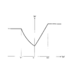
- FIG. 4 is a schematic diagram of a control map showing an example of the relationship between the reference current Ibf and the speed Vpf.
- the reference unit 121 calculates the reference current Ibf according to the speed Vpf.
- the reference unit 121 for example, by substituting the speed Vpf into the control map illustrated in FIG. 4 that shows the relationship between the reference current Ibf and the speed Vpf, which is created in advance based on the rule of thumb and recorded in the ROM,
- the reference current Ibf is calculated.
- the speed Vpf is negative and the speed Vpf is equal to or higher than the first predetermined speed V1
- the smaller the speed Vpf is, the larger the current amount is, and the speed Vpf is the first predetermined speed.
- control map showing an example of the relationship between the reference current Ibr and the speed Vpr is the same as the control map showing the example of the relationship between the reference current Ibf and the speed Vpf, and thus detailed description thereof will be omitted.
- the specific values of the first predetermined speed V1, the second predetermined speed V2, and the constant current amount are the reference current Ibf and the speed Vpf. It may be the same as or different from the case of the control map indicating the relationship.
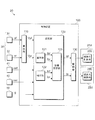
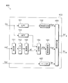
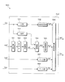
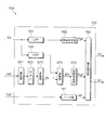
- FIG. 5 is a diagram showing a schematic configuration of the correction unit 122 according to the first embodiment.
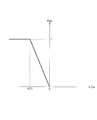
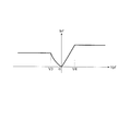
- FIG. 6 is a schematic diagram of a control map showing an example of the relationship between the longitudinal acceleration Gx and the correction coefficient Kgx.
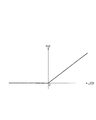
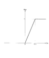
- FIG. 7 is a schematic diagram of a control map showing an example of the relationship between the acceleration difference ⁇ Gf and the correction coefficient Kgf.
- FIG. 8 is a schematic diagram of a control map showing an example of the relationship between the base current Ief and the speed Vpf.
- the correction unit 122 has an LPF 151 that performs a filtering process corresponding to a low-pass filter on the longitudinal acceleration Gx detected by the longitudinal G sensor 50.
- the correction unit 122 also includes a coefficient setting unit 152 that sets a correction coefficient Kgx that is output from the LPF 151 and that corresponds to the longitudinal acceleration Gx after the filtering process.
- the correction unit 122 also includes an HPF 153 that performs a filtering process corresponding to a high-pass filter on the longitudinal acceleration Gx detected by the longitudinal G sensor 50.
- the coefficient setting unit 152 substitutes the longitudinal acceleration Gx into the control map illustrated in FIG. 6, which is created based on an empirical rule in advance and is recorded in the ROM, and which shows the relationship between the longitudinal acceleration Gx and the correction coefficient Kgx. Then, the correction coefficient Kgx is calculated. In the control map illustrated in FIG.
- the correction coefficient Kgx is positive when the longitudinal acceleration Gx is smaller than 0 (g), and the correction coefficient Kgx when the longitudinal acceleration Gx is 0 (g) or more. Is 0.
- the correction coefficient Kgx is 1, and the correction coefficient increases as the longitudinal acceleration Gx increases from ⁇ 0.3 (g) to 0 (g). Kgx decreases from 1 to 0.
- the correction unit 122 also includes a calculation unit 161 that calculates the rotational acceleration of the front wheels 2, and a BPF 162 that performs a filtering process corresponding to a bandpass filter on the rotational acceleration calculated by the calculation unit 161.
- the correction unit 122 also includes a conversion unit 163 that converts the unit of the rotational acceleration after the filtering process, which is output from the BPF 162, into the gravitational acceleration (g).
- the calculation unit 161 calculates the rotational acceleration (km/h/s) of the front wheel 2 using (by differentiating) the rotational speed signal vwf from the wheel speed sensor 41.
- the conversion unit 163 converts the unit of the rotational acceleration (km/h/s) of the front wheel 2 after the filtering process by the BPF 162, which is calculated by the calculation unit 161, into the gravitational acceleration (g), and the converted value is obtained. Output.
- the value of the rotational acceleration of the front wheel 2 after conversion, whose unit is converted into the gravitational acceleration (g) by the conversion unit 163, may be referred to as the front wheel acceleration Af(g).
- the correction unit 122 also includes a subtraction unit 164 that subtracts the filtered longitudinal acceleration Gx output from the HPF 153 from the front wheel acceleration Af output from the conversion unit 163.
- the coefficient setting unit 165 substitutes the acceleration difference ⁇ Gf into a control map illustrated in FIG. 7, which is created based on an empirical rule in advance and is recorded in the ROM, and which illustrates the relationship between the acceleration difference ⁇ Gf and the correction coefficient Kgf. Then, the correction coefficient Kgf is calculated.
- the correction coefficient Kgf is 0 when the acceleration difference ⁇ Gf is 0 (g) or less, and is set to the acceleration difference ⁇ Gf when the acceleration difference ⁇ Gf is larger than 0 (g). It is a proportional positive value.
- the correction unit 122 also includes a base unit 181 that sets the base current Ief that is the base of the correction current Icf according to the speed Vpf.
- the base unit 181 substitutes the speed Vpf into the control map illustrated in FIG. 8 that shows the relationship between the base current Ief and the speed Vpf, which is created in advance based on the rule of thumb and recorded in the ROM. Set the base current Ief.
- the speed Vpf is negative and the speed Vpf is equal to or higher than the third predetermined speed V3
- the amount of current is set to be constant.
- the LPF 151 does not attenuate the frequency components lower than the cutoff frequency in the output values from the front and rear G sensors 50, but performs the filtering process to attenuate the frequency components higher than the cutoff frequency.
- the LPF 151 has a function of canceling the noise of the output values from the front and rear G sensors 50 and matching of the time constant.
- the HPF 153 performs a filtering process of attenuating a frequency component lower than the cutoff frequency but not a frequency component higher than the cutoff frequency among the output values from the front and rear G sensors 50. As described above, since the subtraction unit 164 subtracts the longitudinal acceleration Gx from the front wheel acceleration Af, the HPF 153 has a function of removing the time difference between the values of both accelerations.
- a filter that does not pass (attenuates) a frequency lower than a desired frequency and does not pass (attenuates) a frequency higher than a desired frequency and performs a filtering process corresponding to a bandpass filter is used. Is also good.
- a unit that performs a filtering process corresponding to the low-pass filter may be additionally provided after the HPF 153 and before the subtraction unit 164. Further, a unit that performs a filtering process corresponding to the low-pass filter may be additionally provided in front of the HPF 153.
- the BPF 162 performs a filtering process that passes only a desired frequency band and does not pass (attenuate) other frequencies.
- the BPF 162 has a function of canceling the offset of the output value from the calculation unit 161, canceling the noise, and matching the time constant.
- the BPF 162 has a function of performing a filtering process corresponding to a high-pass filter that does not pass (attenuate) a frequency lower than a desired frequency, and a filtering process corresponding to a low-pass filter that does not pass (attenuate) a frequency higher than a desired frequency. It may be configured by combining different elements each having the function of performing. It should be noted that instead of the BPF 162, a device that performs filtering processing corresponding to a high-pass filter may be provided. Further, instead of the BPF 162, a device that performs filtering processing corresponding to a low pass filter may be provided.
- the correction unit 122 sets the correction current Icf using the correction coefficient Kgx set by the coefficient setting unit 152, the correction coefficient Kgf set by the coefficient setting unit 165, and the base current Ief set by the base unit 181.
- the LPF 151, the coefficient setting unit 152, the HPF 153, the calculation unit 161, the BPF 162, the conversion unit 163, the subtraction unit 164, the coefficient setting unit 165, the base unit 181, and the correction setting unit 190 described above predetermined the above processing. It is repeated every period (for example, 1 millisecond).
- FIG. 9 is a diagram showing the behavior when the brake operation is performed in the first comparison vehicle.
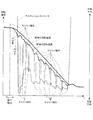
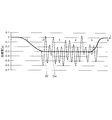
- FIG. 10 is a diagram showing a temporal change between the longitudinal acceleration Gx and the front wheel acceleration Af when the brake operation is performed in the first comparative vehicle.
- FIG. 11 is a diagram showing the behavior of the motorcycle 1 when a brake operation is performed.
- the motorcycle 1 that does not include the correction unit 122 of the control device 100 and does not add the correction currents Icf and Icr to the motorcycle 1 is referred to as a first comparison vehicle.
- the brake pressure of the caliper 62 rises, and the braking torque acts on the front wheels 2. Therefore, as shown in FIG.
- the rotation speed of the front wheels 2 becomes abruptly lower than the rotation speed of the wheels 3.
- the ABS 80 reduces the brake pressure of the caliper 62, and the braking torque decreases.
- the front wheels 2 start to accelerate due to the decrease in the braking torque and the slip ratio of the front wheels 2 becomes smaller, the brake pressure is increased to increase the braking torque again. The above cycle is repeated until the first comparison vehicle is stopped.
- the brake pressure of the caliper 62 is increased and the braking torque is increased, so that the front wheel acceleration Af becomes smaller than the longitudinal acceleration Gx.
- the braking torque decreases and the acceleration of the front wheels 2 increases, so that the front wheel acceleration Af becomes larger than the longitudinal acceleration Gx.
- the longitudinal acceleration Gx is negative until the first comparative vehicle stops after the brake operation is performed. Focusing on the suspension 21 on the front wheel 2 side, when the braking torque of the front wheel 2 increases, the suspension 21 contracts, and thereafter, the braking torque decreases and the front wheel acceleration Af increases, so that the suspension 21 extends. Therefore, after the sudden braking operation is performed, the cycle of increasing and decreasing the braking torque is repeated until the first comparison vehicle stops, so that the contracting operation and the extending operation of the suspension 21 are repeated, and vibration is generated. It will be easier.
- the coefficient setting unit 165 sets the correction coefficient Kgf to a value larger than 0 (a positive value). Value). Further, when the brake operation is performed, the longitudinal acceleration Gx becomes a value smaller than 0 (negative value), so the coefficient setting unit 152 sets the correction coefficient Kgx to a value larger than 0 (positive value). ). Further, when the speed Vpf is a value smaller than 0 and when the speed Vpf is a value larger than 0, the base portion 181 sets the base current Ief to a value larger than 0 (a positive value). Set to.
- the correction setting unit 190 sets the positive correction current Icf when the front wheel acceleration Af is larger than the longitudinal acceleration Gx.
- the power increases.
- vibration is less likely to occur.
- the amplitude becomes small. That is, according to the control device 100, the behavior of the motorcycle 1 is stable even if a sudden braking operation is performed. Therefore, the steering feeling is improved.
- the motorcycle 1 stops early.
- the control device 100 even if a sudden braking operation is performed, the amplitude of vibration can be reduced and the cycle of vibration can be shortened. This stabilizes the behavior of the motorcycle 1 and makes it difficult for the driver to feel the swing. Therefore, by including the control device 100, it is possible to provide the motorcycle 1 in which the behavior when a sudden braking operation is performed is stable and the steering feeling can be improved.
- the control device 100 controls the damping force of the damping device 21d that damps the force generated between the vehicle body 10 and the front wheel 2 as an example of the wheel to the longitudinal acceleration Gx of the vehicle body 10 and the front wheel 2.
- Control is performed using the difference from the front wheel acceleration Af, which is an example of rotational acceleration.
- the longitudinal acceleration Gx and the front wheel acceleration Af are indices for grasping the behavior of the motorcycle 1. Therefore, by controlling the damping force of the damping device 21d using these values, it is possible to stabilize the behavior of the vehicle.
- the situation in which the front wheel acceleration Af is larger than the longitudinal acceleration Gx when the longitudinal acceleration Gx is less than 0 (g), that is, when the vehicle body 10 is decelerating does not occur unless the brake operation is performed.
- the situation. in such a situation, by increasing the damping force of the damping device 21d, it is possible to prevent the operation of the suspension 21 from becoming unstable.
- the front wheels 2 are accelerating when the vehicle body 10 is decelerating, it is considered that the suspension 21 is operating in the extending direction even though the vehicle body 10 is decelerating, and therefore the damping
- By increasing the damping force of the device 21d in the extension direction it is possible to prevent the operation of the suspension 21 from becoming unstable.
- control device 100 operates the ABS 80 so as to control the brake device 60, which is an example of a braking device capable of adjusting the braking torque generated on the front wheels 2, to control the slip state of the front wheels 2 (the caliper 62). It can also be understood as a device for determining whether or not the brake pressure is reduced. Then, when the control device 100 determines that the ABS 80 is operating, the control device 100 increases the damping force more than when it is not determined that the ABS 80 is operating.
- the controller 100 controls the brake device 60 to slip the front wheels 2 when the longitudinal acceleration Gx is less than 0 (g), that is, when the front wheel acceleration Af is greater than the longitudinal acceleration Gx when the vehicle body 10 is decelerating.
- the ABS 80 is operating so as to control the state.
- the inventors of the present invention have earnestly studied that when the brake pressure of the caliper 62 is reduced by the ABS 80, the front wheel acceleration Af becomes 0 when the longitudinal acceleration Gx is ⁇ 0.3 (g) or less. It was found that a peculiar situation of 0.1 (g) or more can occur. Therefore, for example, when the front-wheel acceleration Af is larger than the front-rear acceleration Gx when the front-rear acceleration Gx is ⁇ 0.3 (g) or less, the damping force in the extension direction of the damping device 21d is increased to increase the sudden force. Vibration generated due to the brake pressure being reduced by the ABS 80 during brake operation can be suppressed with high accuracy.
- the correction unit 122 may set the correction current Icf by further considering the vehicle speed that is the moving speed of the motorcycle 1. For example, the correction unit 122 sets the correction current Icf to 0 when the vehicle speed is, for example, less than 5 (km/h), and sets as described above when the vehicle speed is, for example, 5 (km/h) or more.
- the corrected current Icf may be set as the final corrected current Icf. Further, the correction unit 122 may not output 0 as the correction current Icr, but may not output the correction current Icr.
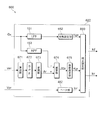
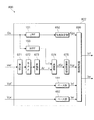
- FIG. 12 is a diagram showing a schematic configuration of the correction unit 422 of the control device 400 according to the second embodiment.
- the control device 400 according to the second embodiment is different from the control device 100 according to the first embodiment in the correction unit 422 corresponding to the correction unit 122.
- differences from the control device 100 will be described.
- those having the same function are denoted by the same reference numerals, and detailed description thereof will be omitted.
- the correction unit 422 has a base unit 482 that sets the base current Ier that is the base of the correction current Icr according to the speed Vpr, instead of the base unit 181 included in the correction unit 122.
- the method by which the base portion 482 calculates the base current Ier is the same as the method by which the base portion 181 calculates the base current Ief, and thus detailed description thereof will be omitted.
- the control map showing an example of the relationship between the base current Ier and the speed Vpr is the same as the control map showing an example of the relationship between the base current Ief and the speed Vpf, and thus detailed description thereof will be omitted.
- the specific values of the third predetermined speed V3, the fourth predetermined speed V4, and the constant current amount are the same as those in the control map showing an example of the relationship between the base current Ief and the speed Vpf. Good or different. It is possible to exemplify that the base current Ier is a positive current amount smaller than the reference current Ibr regardless of the speed Vpr.
- the base unit 482 and the correction setting unit 490 described above repeatedly perform the above-described processing every predetermined period (for example, 1 millisecond).
- the first comparison vehicle when a sudden braking operation is performed by suddenly grasping the brake lever 13, focusing on the suspension 22 on the rear wheel side, when the braking torque of the front wheel 2 increases, the suspension 22 extends, and thereafter.
- the suspension torque is reduced by reducing the braking torque and accelerating the front wheels 2. Therefore, after the sudden braking operation is performed, the cycle of increasing and decreasing the braking torque is repeated until the first comparison vehicle stops, so that the extension operation and the contraction operation of the suspension 22 are repeated, and vibration is generated. It will be easier.
- the base portion 482 has the speed Vpr smaller than 0 and the speed Vpr larger than 0.
- the base current Ier is set to a value larger than 0 (positive value). Therefore, the correction setting unit 490 sets the positive correction current Icr when the front wheel acceleration Af is larger than the longitudinal acceleration Gx.
- the correction unit 422 may set the correction current Icr by further considering the vehicle speed that is the moving speed of the motorcycle 1. For example, the correction unit 422 sets the correction current Icr to 0 when the vehicle speed is less than 5 (km/h), and sets as described above when the vehicle speed is 5 (km/h) or more. The corrected current Icr may be set as the final corrected current Icr. The correction unit 422 may not output 0 as the correction current Icf, but may not output the correction current Icf.
- FIG. 13 is a diagram showing a schematic configuration of the correction unit 522 of the control device 500 according to the third embodiment.
- the control device 500 according to the third embodiment is different from the control device 100 according to the first embodiment in a correction unit 522 corresponding to the correction unit 122.
- differences from the control device 100 will be described.
- those having the same function are denoted by the same reference numerals, and detailed description thereof will be omitted.
- the correction unit 522 includes a base unit 482 included in the correction unit 422 according to the second embodiment, in addition to the base unit 181 included in the correction unit 122. Further, the correction unit 522 has, in place of the correction setting unit 190, a correction setting unit 590 that sets the correction current Icr in addition to setting the correction current Icf.
- the correction setting unit 590 sets the correction current Icf using the same method as the correction setting unit 190. Further, the correction setting unit 590 sets the correction current Icr by using the same method as the correction setting unit 490 according to the second embodiment.
- the control device 500 according to the third embodiment it is possible to obtain the effect of the control device 100 according to the first embodiment and the effect of the control device 400 according to the second embodiment.
- the control device 500 the amplitude of vibration can be reduced and the cycle of vibration can be shortened even when a sudden braking operation is performed. This stabilizes the behavior of the motorcycle and makes it difficult for the driver to feel the swing. Therefore, by including the control device 500, it is possible to provide a motorcycle in which the behavior when a sudden braking operation is performed is stable and the steering feeling can be improved.
- FIG. 14 is a diagram showing a schematic configuration of the correction unit 622 of the control device 600 according to the fourth embodiment.
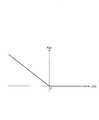
- FIG. 15 is a schematic diagram of a control map showing an example of the relationship between the longitudinal acceleration Gx and the correction coefficient Kgx.
- FIG. 16 is a schematic diagram of a control map showing an example of the relationship between the acceleration difference ⁇ Gr and the correction coefficient Kgr.
- the control device 600 according to the fourth embodiment is different from the control device 100 according to the first embodiment in the correction unit 622 corresponding to the correction unit 122.
- differences from the control device 100 will be described.
- those having the same function are designated by the same reference numerals, and detailed description thereof will be omitted.
- the correction unit 622 has, in place of the coefficient setting unit 152, a coefficient setting unit 652 that sets a correction coefficient Kgx that is output from the LPF 151 and that corresponds to the longitudinal acceleration Gx after the filtering process.
- the coefficient setting unit 652 substitutes the longitudinal acceleration Gx into the control map illustrated in FIG. 15, which shows the relationship between the longitudinal acceleration Gx and the correction coefficient Kgx, which is created in advance based on an empirical rule and recorded in the ROM, for example. Then, the correction coefficient Kgx is calculated.
- the longitudinal acceleration Gx is greater than 0 (g)
- the correction coefficient Kgx is positive
- the longitudinal acceleration Gx is 0 (g) or less
- the correction coefficient Kgx when the longitudinal acceleration Gx is 0 (g) or less, the correction coefficient Kgx. Is 0.
- the longitudinal acceleration Gx is 0.3 (g) or more, the correction coefficient Kgx is 1, and the correction coefficient Kgx increases as the longitudinal acceleration Gx increases from 0 (g) to 0.3
- the correction unit 622 corresponds to a calculation unit 671 that calculates the rotational acceleration of the rear wheel 3 instead of the calculation unit 161 and the BPF 162 that the correction unit 122 has, and a rotational speed calculated by the calculation unit 671 that corresponds to a bandpass filter.
- a BPF 672 for performing filtering processing.
- the correction unit 622 has a conversion unit 673, which replaces the conversion unit 163 included in the correction unit 122, that converts the unit of the rotational acceleration after the filtering process, which is output from the BPF 672, into the gravitational acceleration (g). ..
- the calculation unit 671 calculates the rotational acceleration (km/h/s) of the rear wheel 3 using (by differentiating) the rotational speed signal vwr from the wheel speed sensor 42.
- the conversion unit 673 converts the unit of the rotational acceleration (km/h/s) of the rear wheel 3 after the filtering processing by the BPF 672, which is calculated by the calculation unit 671, into the gravitational acceleration (g), and the converted value is Output.
- the value of the rotational acceleration of the rear wheel 3 after conversion, whose unit is converted into the gravitational acceleration (g) by the conversion unit 673 may be referred to as the rear wheel acceleration Ar(g).
- the correction coefficient Kgr is calculated.
- the correction coefficient Kgr is 0 when the acceleration difference ⁇ Gf is 0 (g) or more, and is set to the acceleration difference ⁇ Gf when the acceleration difference ⁇ Gr is smaller than 0 (g). It is a positive value that is inversely proportional.
- the calculation unit 671, the BPF 672, the conversion unit 673, the subtraction unit 674, the coefficient setting unit 675, the base unit 482, and the correction setting unit 690 described above perform the above processing for each predetermined period (for example, 1 millisecond). Repeat.
- the BPF 672 has the same function as the BPF 162, and has the function of canceling the offset of the output value from the calculating unit 671, canceling the noise, and matching the time constant.
- the BPF 672 may be configured by combining different elements each having a function of performing a filtering process corresponding to a high pass filter and a function of performing a filtering process corresponding to a low pass filter. It should be noted that instead of the BPF 672, a device that performs filtering processing corresponding to a high pass filter may be provided. Further, instead of the BPF 672, a device that performs a filtering process corresponding to a low pass filter may be provided.
- the control device 600 configured as described above operates as follows.
- a motorcycle that does not include the correction unit 622 of the control device 600 and does not add the correction currents Icf and Icr to the motorcycle that has the control device 600 is referred to as a second comparison vehicle.
- the second comparison vehicle when a sudden acceleration operation is performed by suddenly turning the throttle grip 17, the engine torque sharply increases and the driving torque of the rear wheels 3 sharply increases. The rotation speed of the rear wheel 3 suddenly becomes higher than the rotation speed. Then, when the rear wheels 3 run idle, the driving torque of the rear wheels 3 is reduced by the TCS 90. When the rear wheels 3 start to decelerate due to the decrease in the driving torque and the rear wheels 3 stop idling, the TCS 90 stops operating and the driving torque increases again. The above cycle is repeated until the throttle grip 17 of the second comparison vehicle is returned.
- the coefficient setting unit 675 sets the correction coefficient Kgr to be larger than 0. Set to a large value (positive value). Further, when the acceleration operation is performed, the longitudinal acceleration Gx becomes a value (a positive value) larger than 0. Therefore, the coefficient setting unit 652 sets the correction coefficient Kgx to a value larger than 0 (a positive value). ). Further, the base unit 482 sets the base current Ier to a value (a positive value) larger than 0 when the speed Vpr is a value smaller than 0 and when the speed Vpr is a value larger than 0. Set to.
- the correction setting unit 690 sets the positive correction current Icr when the rear wheel acceleration Ar is smaller than the longitudinal acceleration Gx.
- the suspension 22 becomes difficult to extend.
- vibration is less likely to occur.
- the amplitude becomes small. That is, according to the control device 600, the behavior of the motorcycle having the control device 600 is stable even if a rapid acceleration operation is performed. Therefore, the steering feeling is improved.
- the TCS 90 when the sudden acceleration operation is performed, the TCS 90 is actuated to reduce the driving torque of the rear wheels 3 and thus the suspension 22 becomes difficult to extend. Then, the TCS 90 is deactivated and the rear wheels 3 are driven. The spring force increases as the torque increases. As a result, the ground contact load of the rear wheel 3 with the road surface increases at an early stage. Then, when the TCS 90 is deactivated and the drive torque increases, and the rear wheel 3 idles again, the TCS 90 reduces the drive torque of the rear wheel 3. As a result, the cycle of the cycle in which the TCS 90 is deactivated, the TCS 90 is activated again, and then the TCS 90 is deactivated again, the cycle period is shortened.
- the suspension 22 operates in the extension direction, the compression direction, and the extension direction.
- the cycle for switching to the operation becomes short.
- the speed of the motorcycle having the control device 600 is increased at an early stage.
- the amplitude of vibration can be reduced and the cycle of vibration can be shortened even if a rapid acceleration operation is performed. This stabilizes the behavior of the motorcycle having the control device 600, and makes it difficult for the driver to feel the swing. Therefore, by including the control device 600, it is possible to provide a motorcycle in which the behavior when a sudden acceleration operation is performed is stable and the steering feeling can be improved.
- the control device 600 controls the damping force of the damping device 22d that damps the force generated between the vehicle body 10 and the rear wheel 3 as an example of the wheel to the longitudinal acceleration Gx of the vehicle body 10 and the rear wheel. Control is performed using the difference from the rear wheel acceleration Ar as an example of the rotational acceleration of No. 3. As exemplified in the case where the sudden acceleration operation is performed, the longitudinal acceleration Gx and the rear wheel acceleration Ar are indices for grasping the behavior of the motorcycle having the control device 600. Therefore, it is possible to stabilize the behavior of the vehicle by controlling the damping force of the damping device 22d using these values.
- the situation where the rear wheel acceleration Ar is smaller than the longitudinal acceleration Gx when the longitudinal acceleration Gx is larger than 0 (g), that is, when the vehicle body 10 is accelerating, is a case where the acceleration operation is not performed. Is a situation that does not occur. In such a situation, it is possible to suppress the operation of the suspension 22 from becoming unstable by increasing the damping force of the damping device 22d.
- the rear wheel 3 is decelerating when the vehicle body 10 is accelerating, it is considered that the suspension 22 is operating in the extension direction even though the vehicle body 10 is accelerating.
- By increasing the damping force of the damping device 22d in the compression direction it is possible to prevent the operation of the suspension 22 from becoming unstable.
- control device 600 can also be regarded as a device that determines whether or not the TCS 90 that controls so as to suppress the idling of the rear wheels 3 is operating. Then, when the control device 600 determines that the TCS 90 is operating, the control device 600 increases the damping force more than when it is not determined that the TCS 90 is operating.
- the control device 600 suppresses idling of the rear wheel 3 when the longitudinal acceleration Gx is larger than 0 (g), that is, when the rear wheel acceleration Ar is smaller than the longitudinal acceleration Gx while the vehicle body 10 is accelerating. It is determined that the TCS 90 is operating as described above.
- the inventors of the present invention have earnestly studied, and when the TCS 90 suppresses the idling of the rear wheel 3, for example, when the longitudinal acceleration Gx is 0.3 (g) or more, the rear wheel acceleration Ar is ⁇ It has been found that a peculiar situation where the value is 0.1 (g) or less can occur. Therefore, for example, when the longitudinal acceleration Gx is 0.3 (g) or more and the rear wheel acceleration Ar is smaller than the longitudinal acceleration Gx, the damping force in the extension direction of the damping device 22d is increased to increase the sudden force. Vibrations caused by the TCS 90 suppressing the idling of the rear wheels 3 during the acceleration operation can be suppressed with high accuracy.
- the correction unit 622 may set the correction current Icr by further considering the vehicle speed that is the moving speed of the motorcycle having the control device 600. For example, the correction unit 622 sets the correction current Icr to 0 when the vehicle speed is less than 5 (km/h), and sets as described above when the vehicle speed is 5 (km/h) or more. The corrected current Icr may be set as the final corrected current Icr. The correction unit 622 may not output 0 as the correction current Icf, but may not output the correction current Icf.
- the control device 600 has the correction unit 122 included in the control device 100 according to the first embodiment and the control device 400 according to the second embodiment.
- the correction unit 422 and any one correction unit selected from the group of the correction unit 522 included in the control device 500 according to the third embodiment may be included.
- the target setting unit 123 uses the correction currents Icf and Icr set by the correction unit 622 and the correction currents Icf and Icr set by one correction unit (for example, the correction unit 122) to set the target currents Itf and Itr. You may set it.
- the target setting unit 123 includes the reference currents Ibf and Ibr set by the reference unit 121, the correction currents Icf and Icr set by the correction unit 622, and the correction current Icf set by one correction unit (for example, the correction unit 122).
- Icr may be set to the target currents Itf and Itr.
- FIG. 17 is a diagram showing a schematic configuration of the correction unit 722 of the control device 700 according to the fifth embodiment.
- the control device 700 according to the fifth embodiment is different from the control device 600 according to the fourth embodiment in a correction unit 722 corresponding to the correction unit 622.
- differences from the control device 600 will be described.
- those having the same function are designated by the same reference numerals, and detailed description thereof will be omitted.
- the correction unit 722 has a base unit 181 included in the correction unit 122 according to the first embodiment, instead of the base unit 482 included in the correction unit 622.
- the correction unit 722 instead of the correction setting unit 690, multiplies the correction coefficient Kgx set by the coefficient setting unit 652, the correction coefficient Kgr set by the coefficient setting unit 675, and the base current Ief set by the base unit 181. It has a correction setting unit 790 that sets the value obtained by doing so as the correction current Icf.
- the correction setting unit 790 sets the correction current Icr to 0.
- the correction setting unit 790 repeats the above-described processing every predetermined period (for example, 1 millisecond).
- the coefficient setting unit 675 causes the correction coefficient Kgr to change. Is set to a value larger than 0 (a positive value). Further, when the acceleration operation is performed, the longitudinal acceleration Gx becomes a value (a positive value) larger than 0. Therefore, the coefficient setting unit 652 sets the correction coefficient Kgx to a value larger than 0 (a positive value). ). Further, when the speed Vpf is a value smaller than 0 and when the speed Vpf is a value larger than 0, the base portion 181 sets the base current Ief to a value larger than 0 (a positive value). Set to.
- the correction setting unit 790 sets the positive correction current Icf when the rear wheel acceleration Ar is smaller than the longitudinal acceleration Gx.
- the suspension 21 becomes difficult to contract.
- vibration is less likely to occur. Further, even if vibration occurs, the amplitude becomes small.
- the cycle of the TCS 90 being deactivated, the TCS 90 being activated again, and the TCS 90 being deactivated again is shortened.
- the control device 700 even if a rapid acceleration operation is performed, the amplitude of vibration can be reduced and the cycle of vibration can be shortened. This stabilizes the behavior of the motorcycle and makes it difficult for the driver to feel the swing. Therefore, by including the control device 700, it is possible to provide a motorcycle in which the behavior when the sudden acceleration operation is performed is stable and the steering feeling can be improved.
- the correction unit 722 may set the correction current Icf by further considering the vehicle speed that is the moving speed of the motorcycle having the control device 700. For example, the correction unit 722 sets the correction current Icf to 0 when the vehicle speed is less than 5 (km/h), and sets as described above when the vehicle speed is 5 (km/h) or more. The corrected current Icf may be set as the final corrected current Icf. The correction unit 722 may not output 0 as the correction current Icr, but may not output the correction current Icr.
- the control device 700 has the correction unit 122 included in the control device 100 according to the first embodiment and the control device 400 according to the second embodiment.
- the correction unit 422 and any one correction unit selected from the group of the correction unit 522 included in the control device 500 according to the third embodiment may be included.
- the target setting unit 123 uses the correction currents Icf and Icr set by the correction unit 722 and the correction currents Icf and Icr set by one correction unit (for example, the correction unit 122) to set the target currents Itf and Itr. You may set it.
- the target setting unit 123 includes the reference currents Ibf and Ibr set by the reference unit 121, the correction currents Icf and Icr set by the correction unit 722, and the correction current Icf set by one correction unit (for example, the correction unit 122).
- Icr may be set to the target currents Itf and Itr.
- FIG. 18 is a diagram showing a schematic configuration of the correction unit 822 of the control device 800 according to the sixth embodiment.
- the control device 800 according to the sixth embodiment is different from the control device 600 according to the fourth embodiment in the correction unit 822 corresponding to the correction unit 622.
- differences from the control device 600 will be described.
- the control device 600 and the control device 800 having the same function are denoted by the same reference numerals, and detailed description thereof will be omitted.
- the correction unit 822 has a base unit 182 included in the correction unit 122 according to the first embodiment, in addition to the base unit 482 included in the correction unit 622. Further, the correction unit 822 has, in place of the correction setting unit 690, a correction setting unit 890 that sets the correction current Icf in addition to setting the correction current Icr.
- the correction setting unit 890 sets the correction current Icr using the same method as the correction setting unit 690. Further, the correction setting unit 890 sets the correction current Icf using the same method as the correction setting unit 790 according to the fifth embodiment. According to the control device 800 according to the sixth embodiment, it is possible to obtain the effect of the control device 600 according to the fourth embodiment and the effect of the control device 700 according to the fifth embodiment.
- the control device 800 the amplitude of vibration can be reduced and the cycle of vibration can be shortened even if a rapid acceleration operation is performed. This stabilizes the behavior of the motorcycle and makes it difficult for the driver to feel the swing. Therefore, by including the control device 800, it is possible to provide a motorcycle in which the behavior when a sudden acceleration operation is performed is stable and the steering feeling can be improved.
- the control device 800 according to the sixth embodiment includes, in addition to the correction unit 822, the correction unit 122 included in the control device 100 according to the first embodiment and the control device 400 according to the second embodiment.
- the correction unit 422 and any one correction unit selected from the group of the correction unit 522 included in the control device 500 according to the third embodiment may be included.
- the target setting unit 123 uses the correction currents Icf and Icr set by the correction unit 822 and the correction currents Icf and Icr set by one correction unit (for example, the correction unit 122) to set the target currents Itf and Itr. You may set it.
- the target setting unit 123 includes the reference currents Ibf and Ibr set by the reference unit 121, the correction currents Icf and Icr set by the correction unit 822, and the correction current Icf set by one correction unit (for example, the correction unit 122).
- Icr may be set to the target currents Itf and Itr.
- the components of the control device may be realized by hardware or software.
- the software (computer program) can be provided in a form stored in a computer-readable recording medium.
- the “computer-readable recording medium” is not limited to a portable recording medium such as a flexible disk or a CD-ROM, but various types of RAM, ROM, and other internal storage devices in the computer, and external storage devices such as hard disks. Also includes.
Landscapes
- Engineering & Computer Science (AREA)
- Mechanical Engineering (AREA)
- Axle Suspensions And Sidecars For Cycles (AREA)
- Regulating Braking Force (AREA)
- Vehicle Body Suspensions (AREA)
Abstract
制御装置は、車両本体と前輪との間に生じる力を減衰させる減衰装置の減衰力を、車両本体の前後加速度Gxと、前輪の回転加速度Afとの差を用いて制御する。
Description
本発明は、制御装置、懸架システムに関する。
従来、車両挙動が不安定になったときにも車体姿勢を適正化することができる制御装置が提案されている。
例えば、特許文献1に記載されたサスペンション制御装置は、車輪速センサが検出した車輪速変動量に基づいて車両の基本入力量を算出する基本入力量算出手段と、基本入力量に基づいて第1目標電流を設定する第1目標電流設定手段と、加速度センサが検出した車体加速度に基づいて第2目標電流を設定する第2目標電流設定手段と、車両の挙動を制御する車両挙動制御装置の非作動時には第1目標電流に基づいて、車両挙動制御装置の作動時には第2目標電流に基づいてダンパを制御するダンパ制御手段とを備える。
例えば、特許文献1に記載されたサスペンション制御装置は、車輪速センサが検出した車輪速変動量に基づいて車両の基本入力量を算出する基本入力量算出手段と、基本入力量に基づいて第1目標電流を設定する第1目標電流設定手段と、加速度センサが検出した車体加速度に基づいて第2目標電流を設定する第2目標電流設定手段と、車両の挙動を制御する車両挙動制御装置の非作動時には第1目標電流に基づいて、車両挙動制御装置の作動時には第2目標電流に基づいてダンパを制御するダンパ制御手段とを備える。
車両の挙動を安定させるためには、懸架装置に生じる振動を低減することが望ましい。
特許文献1に開示されている技術には、車両の挙動を安定させるという点で、さらなる改善の余地があった。
本発明は、車両の挙動を安定させるように減衰装置の減衰力を制御する制御装置等を提供することを目的とする。
特許文献1に開示されている技術には、車両の挙動を安定させるという点で、さらなる改善の余地があった。
本発明は、車両の挙動を安定させるように減衰装置の減衰力を制御する制御装置等を提供することを目的とする。
本発明者らは、ブレーキ操作後の車両挙動、より具体的には、ブレーキ操作後の前輪の車輪速、後輪の車輪速、及び、サスペンション挙動の時間変化を解析した。また、本発明者らは、スロットルグリップ操作後の車両挙動を解析した。その結果、車両本体の前後加速度と車輪の回転加速度との差を用いて、減衰装置の減衰力を制御することにより、車両の挙動を安定させることが可能になることを知見した。本発明者らは、このような知見に基づいて本発明を完成させた。
以下、本発明について説明する。以下の説明では、本発明の理解を容易にするために添付図面中の参照符号を括弧書きで付記するが、それによって本発明が図示の形態に限定されるものではない。
第1の形態は、車両本体(10)と車輪(2、3)との間に生じる力を減衰させる減衰装置(21d、22d)の減衰力を、前記車両本体(10)の前後加速度(Gx)と、前記車輪(2、3)の回転加速度(Af、Ar)との差を用いて制御する、制御装置(100、400、500、600、700、800)である。
ここで、前記車輪が前輪(2)であり、前記前輪(2)側に配置された第1減衰装置(21d)、及び、後輪(3)側に配置された第2減衰装置(22d)の、一方又は両方の減衰力を制御しても良い。
また、上記第1の形態において、前記前輪(2)の前記回転加速度(Af)が前記前後加速度(Gx)よりも大きい場合に、前記第1減衰装置(21d)における、前記車両本体(10)と前記前輪(2)との間の相対変位が大きくなる伸長方向の減衰力、及び、前記第2減衰装置(22d)における、前記車両本体(10)と前記後輪(3)との間の相対変位が小さくなる圧縮方向の減衰力の、一方又は両方を大きくするように制御しても良い。
また、上記第1の形態において、前記前後加速度(Gx)が0(g)未満であっても良い。
また、上記第1の形態において、前記前輪(2)の前記回転加速度(Af)が前記前後加速度(Gx)よりも大きい場合に、前記前輪(2)に生じる制動トルクを調整可能な制動装置(60)を制御して前記前輪(2)のスリップ状態を制御するようにアンチロックブレーキシステム(80)が作動していると判断しても良い。
また、上記第1の形態において、前記アンチロックブレーキシステム(80)が作動していると判断した場合には、前記アンチロックブレーキシステム(80)が作動していると判断していない場合よりも前記減衰力を大きくするように制御しても良い。
さらに、上記第1の形態において、前記車輪が後輪(3)であり、前輪(2)側に配置された第1減衰装置(21d)、及び、前記後輪(3)側に配置された第2減衰装置(22d)の、一方又は両方の減衰力を制御しても良い。
また、上記第1の形態において、前記後輪(3)の前記回転加速度(Ar)が前記前後加速度(Gx)よりも小さい場合に、前記第1減衰装置(21d)における、前記車両本体(10)と前記前輪(2)との間の相対変位が小さくなる圧縮方向の減衰力、及び、前記第2減衰装置(22d)における、前記車両本体(10)と前記後輪(3)との間の相対変位が大きくなる伸長方向の減衰力の、一方又は両方を大きくするように制御しても良い。
また、車輪が後輪(3)である上記第1の形態において、前記前後加速度が0(g)よりも大きくても良い。
また、上記第1の形態において、前記後輪(3)の前記回転加速度(Ar)が前記前後加速度(Gx)よりも小さい場合に、前記後輪(3)の空転を抑制するように制御するトラクションコントロールシステム(90)が作動していると判断しても良い。
また、上記第1の形態において、前記トラクションコントロールシステム(90)が作動していると判断した場合は、前記トラクションコントロールシステム(90)が作動していると判断していない場合よりも前記減衰力を大きくするように制御しても良い。
また、上記第1の形態において、前記車両本体(10)の前後加速度(Gx)を検出するセンサ(50)にて検出された前記前後加速度(Gx)にハイパスフィルタに対応するフィルタリング処理を施した後の前記前後加速度(Gx)と、前記回転加速度(Af、Ar)との差を用いて制御しても良い。
また、上記第1の形態において、前記車両本体(10)の前後加速度(Gx)を検出するセンサ(50)にて検出された前記前後加速度(Gx)に、バンドパスフィルタに対応するフィルタリング処理、又は、ハイパスフィルタに対応するフィルタリング処理及びローパスフィルタに対応するフィルタリング処理、を施した後の前記前後加速度(Gx)と、前記回転加速度(Af、Ar)との差を用いて制御しても良い。
また、上記第1の形態において、前記車輪(2、3)の回転速度を検出するセンサ(41、42)にて検出された前記回転速度を用いて算出した前記回転加速度(Af、Ar)に、ハイパスフィルタに対応するフィルタリング処理を施した後の前記回転加速度(Af、Ar)と、前記前後加速度(Gx)との差を用いて制御しても良い。
また、上記第1の形態において、前記車輪(2、3)の回転速度を検出するセンサ(41、42)にて検出された前記回転速度を用いて算出した前記回転加速度(Af、Ar)に、バンドパスフィルタに対応するフィルタリング処理、又は、ハイパスフィルタに対応するフィルタリング処理及びローパスフィルタに対応するフィルタリング処理、を施した後の前記回転加速度(Af、Ar)と、前記前後加速度(Gx)との差を用いて制御しても良い。
また、第2の形態は、上記第1の形態の制御装置(100、400、500、600、700、800)と、前記制御装置(100、400、500、600、700、800)によって減衰力が制御されるサスペンション(21)とを備えた、懸架システム(20)である。
本発明によれば、車両の挙動を安定させるように減衰装置の減衰力を制御する制御装置等を提供することができる。
以下、添付図面を参照して、本発明の実施の形態について詳細に説明する。
<第1の実施形態>
図1は、第1の実施形態に係る自動二輪車1の概略構成を示す図である。
図2は、第1の実施形態に係る減衰装置200の概略構成を示す図である。
図3は、第1の実施形態に係る制御装置100の概略構成を示す図である。
自動二輪車1は、前側の車輪である前輪2と、後側の車輪である後輪3と、車両本体10とを備えている。車両本体10は、自動二輪車1の骨格をなす車体フレーム11と、ハンドル12と、ブレーキレバー13と、シート14とを有している。シート14に着座した運転者から見た場合のハンドル12の右端部には、ハンドル12の軸に対して回動可能であり、自動二輪車1の加速を指示するスロットルグリップ17が設けられている。
また、自動二輪車1は、前輪2と車両本体10とを連結する前輪側のサスペンション21を有している。また、自動二輪車1は、前輪2の左右それぞれに配置された2つのサスペンション21を保持する2つのブラケット15と、2つのブラケット15の間に配置されたシャフト16とを備えている。サスペンション21は、路面等から前輪2に加わった衝撃を吸収する懸架スプリング21sと、懸架スプリング21sの振動を減衰する減衰装置21dとを備えている。
また、自動二輪車1は、後輪側のサスペンション22を有している。サスペンション22は、路面等から後輪3に加わった衝撃を吸収する懸架スプリング22sと、懸架スプリング22sの振動を減衰する減衰装置22dとを備えている。
以下の説明において、減衰装置21dと減衰装置22dとをまとめて「減衰装置200」と称する場合もある。
以下の説明において、減衰装置21dと減衰装置22dとをまとめて「減衰装置200」と称する場合もある。
自動二輪車1は、サスペンション21の伸縮量を検出するストロークセンサ31と、サスペンション22の伸縮量を検出するストロークセンサ32とを有している。以下の説明において、ストロークセンサ31とストロークセンサ32とをまとめて「ストロークセンサ30」と称する場合もある。
また、自動二輪車1は、前輪2の回転速度を検出する車輪速センサ41と、後輪3の回転速度を検出する車輪速センサ42とを有している。
また、自動二輪車1は、自動二輪車1の前後方向の加速度を検出する、前後加速度センサの一例としての前後Gセンサ50を有している。
また、自動二輪車1は、ストロークセンサ31、32、車輪速センサ41、42及び前後Gセンサ50の検出値を用いて、減衰装置21d及び減衰装置22dの減衰力を制御する制御装置100を備えている。
本発明に係る懸架システム20は、サスペンション21、22と、制御装置100とを有するシステムである。
また、自動二輪車1は、前輪2の回転速度を検出する車輪速センサ41と、後輪3の回転速度を検出する車輪速センサ42とを有している。
また、自動二輪車1は、自動二輪車1の前後方向の加速度を検出する、前後加速度センサの一例としての前後Gセンサ50を有している。
また、自動二輪車1は、ストロークセンサ31、32、車輪速センサ41、42及び前後Gセンサ50の検出値を用いて、減衰装置21d及び減衰装置22dの減衰力を制御する制御装置100を備えている。
本発明に係る懸架システム20は、サスペンション21、22と、制御装置100とを有するシステムである。
また、自動二輪車1は、前輪2側に、ブレーキ装置60を備えている。ブレーキ装置60は、前輪2のハブの外周側に設けられ、かつ、前輪2と一体に回転するディスク61と、ディスク61を挟み込んで前輪2に制動力(摩擦力)を付与するキャリパ62とを有している。また、自動二輪車1は、挟み込みのためのブレーキ圧(油圧)をキャリパ62に供給する前輪側マスターシリンダ(不図示)を有している。
また、自動二輪車1は、後輪3側に、ディスク式のブレーキ装置70を備えている。ブレーキ装置70は、後輪3のハブの外周側に設けられ、かつ、後輪3と一体に回転するディスク71と、ディスク71を挟み込んで後輪3に制動力(摩擦力)を付与するキャリパ72とを有している。また、自動二輪車1は、ブレーキペダル73と、ブレーキペダル73の操作に応じて、キャリパ72にブレーキ圧を供給する後輪側マスターシリンダ(不図示)とを有している。
また、自動二輪車1は、前輪側マスターシリンダとキャリパ62とを接続する配管の途中、及び、後輪側マスターシリンダとキャリパ72とを接続する配管の途中にアンチロックブレーキシステム(Antilock Brake System)80を備えている。アンチロックブレーキシステム80は、前輪2、後輪3の制動時に、前輪2、後輪3のスリップ(ロック)を回避するために、スリップ率が所望のスリップ率となるように、キャリパ62、キャリパ72のブレーキ圧を制御する。以下において、アンチロックブレーキシステム80を、「ABS80」と称する場合もある。
また、自動二輪車1は、駆動輪である後輪3のスリップを検出したときに、後輪3の駆動トルクを低下させる制御を行うことにより、後輪3のスリップを抑制するトラクションコントロールシステム(Traction Control System)90を備えている。トラクションコントロールシステム90が行う後輪3の駆動トルクを低下させる制御としては、エンジン(不図示)の出力トルク(以下、「エンジントルク」と称する場合もある。)を低下させる制御、ブレーキ装置70にて後輪3にブレーキをかける制御等を例示することができる。以下において、トラクションコントロールシステム90を、「TCS90」と称する場合もある。
また、自動二輪車1は、駆動輪である後輪3のスリップを検出したときに、後輪3の駆動トルクを低下させる制御を行うことにより、後輪3のスリップを抑制するトラクションコントロールシステム(Traction Control System)90を備えている。トラクションコントロールシステム90が行う後輪3の駆動トルクを低下させる制御としては、エンジン(不図示)の出力トルク(以下、「エンジントルク」と称する場合もある。)を低下させる制御、ブレーキ装置70にて後輪3にブレーキをかける制御等を例示することができる。以下において、トラクションコントロールシステム90を、「TCS90」と称する場合もある。
(減衰装置)
減衰装置200は、作動油で満たされたシリンダ210と、ピストン221と、ピストンロッド222とを備えている。シリンダ210の一方側(図2においては上側)の端部210aが車両本体10に連結されている。ピストンロッド222は、一方側の端部にピストン221を保持し、他方側(図2においては下側)の端部222aが車輪に連結されている。
シリンダ210内は、ピストン221がシリンダ210内に収容されていることにより、圧縮行程において作動油の圧力が高まる油室211と、伸長行程において作動油の圧力が高まる油室212とに区画されている。
減衰装置200は、作動油で満たされたシリンダ210と、ピストン221と、ピストンロッド222とを備えている。シリンダ210の一方側(図2においては上側)の端部210aが車両本体10に連結されている。ピストンロッド222は、一方側の端部にピストン221を保持し、他方側(図2においては下側)の端部222aが車輪に連結されている。
シリンダ210内は、ピストン221がシリンダ210内に収容されていることにより、圧縮行程において作動油の圧力が高まる油室211と、伸長行程において作動油の圧力が高まる油室212とに区画されている。
減衰装置200は、シリンダ210内の油室211に接続された第1油路231と、シリンダ210内の油室212に接続された第2油路232とを有している。また、減衰装置200は、第1油路231と第2油路232との間に設けられた第3油路233と、第3油路233に設けられた減衰力制御弁240とを有している。また、減衰装置200は、第1油路231と第3油路233の一方の端部とを接続する第1分岐路251と、第1油路231と第3油路233の他方の端部とを接続する第2分岐路252と、を有している。また、減衰装置200は、第2油路232と第3油路233の一方の端部とを接続する第3分岐路253と、第2油路232と第3油路233の他方の端部とを接続する第4分岐路254と、を有している。
また、減衰装置200は、第1分岐路251に設けられた第1チェック弁271と、第2分岐路252に設けられた第2チェック弁272とを有している。また、減衰装置200は、第3分岐路253に設けられた第3チェック弁273と、第4分岐路254に設けられた第4チェック弁274とを有している。また、減衰装置200は、作動油を貯留すると共に作動油を給排する機能を有するリザーバ290と、リザーバ290と第3油路233の他方の端部とを接続するリザーバ通路291とを有している。
減衰力制御弁240は、ソレノイドを有しており、ソレノイドに通電する電流量が制御されることによって、弁を通過する作動油の圧力を制御可能である。本実施の形態に係る減衰力制御弁240は、ソレノイドに供給される電流量が大きくなるのに従って弁を通過する作動油の圧力を高くする。ソレノイドに通電する電流量は、制御装置100によって制御される。
減衰力制御弁240は、ソレノイドを有しており、ソレノイドに通電する電流量が制御されることによって、弁を通過する作動油の圧力を制御可能である。本実施の形態に係る減衰力制御弁240は、ソレノイドに供給される電流量が大きくなるのに従って弁を通過する作動油の圧力を高くする。ソレノイドに通電する電流量は、制御装置100によって制御される。
ピストン221が油室211の方に移動すると、油室211の油圧が上昇する。そして、油室211内の作動油が、第1油路231、及び、第1分岐路251を介して、減衰力制御弁240に向かう。減衰力制御弁240を通過する作動油の圧力が減衰力制御弁240の弁圧にて調整されることにより、圧縮側の減衰力が調整される。減衰力制御弁240を通過した作動油は、第4分岐路254、及び、第2油路232を介して、油室212に流入する。
他方、ピストン221が油室212の方に移動すると、油室212の油圧が上昇する。そして、油室212内の作動油が、第2油路232、及び、第3分岐路253を介して、減衰力制御弁240に向かう。減衰力制御弁240を通過する作動油の圧力が減衰力制御弁240の弁圧にて調整されることにより、伸長側の減衰力が調整される。減衰力制御弁240を通過した作動油は、第2分岐路252、及び、第1油路231を介して、油室211に流入する。
他方、ピストン221が油室212の方に移動すると、油室212の油圧が上昇する。そして、油室212内の作動油が、第2油路232、及び、第3分岐路253を介して、減衰力制御弁240に向かう。減衰力制御弁240を通過する作動油の圧力が減衰力制御弁240の弁圧にて調整されることにより、伸長側の減衰力が調整される。減衰力制御弁240を通過した作動油は、第2分岐路252、及び、第1油路231を介して、油室211に流入する。
(制御装置100)
制御装置100は、CPU、ROM、RAM、バックアップRAM等からなる算術論理演算回路である。
図3に示したように、制御装置100には、ストロークセンサ31にて検出されたサスペンション21のストローク量が出力信号に変換された、前輪側のストローク信号sfが入力される。また、制御装置100には、ストロークセンサ32にて検出されたサスペンション22のストローク量が出力信号に変換された、後輪側のストローク信号srが入力される。このほか、制御装置100には、車輪速センサ41にて検出された前輪2の回転速度が出力信号に変換された、前輪側の回転速度信号vwfが入力される。また、制御装置100には、車輪速センサ42にて検出された後輪3の回転速度が出力信号に変換された、後輪側の回転速度信号vwrが入力される。また、制御装置100には、前後Gセンサ50にて検出された車両本体10の前後方向の加速度が出力信号に変換された、出力信号g等が入力される。
制御装置100は、減衰力制御弁240のソレノイドに供給する電流量を制御することにより、減衰力を制御する。具体的には、制御装置100は、減衰力を大きくする場合には、減衰力制御弁240のソレノイドに供給する電流量を大きくし、減衰力を小さくする場合には、減衰力制御弁240のソレノイドに供給する電流量を小さくする。
制御装置100は、ストロークセンサ30からのストローク信号sf、srを用いて、サスペンション21のストローク量の変化の速度である速度Vpf、及び、サスペンション22のストローク量の変化の速度である速度Vprを算出する、算出部110を備えている。また、制御装置100は、減衰力制御弁240のソレノイドに供給する目標電流Itf、Itrを設定する設定部120と、減衰力制御弁240を駆動させる駆動部130とを備えている。
制御装置100は、ストロークセンサ30からのストローク信号sf、srを用いて、サスペンション21のストローク量の変化の速度である速度Vpf、及び、サスペンション22のストローク量の変化の速度である速度Vprを算出する、算出部110を備えている。また、制御装置100は、減衰力制御弁240のソレノイドに供給する目標電流Itf、Itrを設定する設定部120と、減衰力制御弁240を駆動させる駆動部130とを備えている。
算出部110は、単位時間当たりの、サスペンション21のストローク量の変化量を算出することにより、前輪側の速度Vpfを算出する。また、算出部110は、単位時間当たりの、サスペンション22のストローク量の変化量を算出することにより、後輪側の速度Vprを算出する。なお、以下の説明において、サスペンション21、22の伸長方向における速度Vpの符号を正、サスペンション21、22の圧縮方向における速度Vpの符号を負とする。
設定部120については後で詳述する。
設定部120については後で詳述する。
駆動部130は、例えば電源の正極側ラインと、減衰力制御弁240のソレノイドのコイルとの間に接続された、スイッチング素子としてのトランジスタ(Field Effect Transistor:FET)を備えている。
より具体的には、駆動部130は、減衰装置21dの減衰力制御弁240へと供給する目標電流が、設定部120によって設定された目標電流Itfとなるように、トランジスタをスイッチング動作させる。また、駆動部130は、減衰装置22dの減衰力制御弁240へと供給する目標電流が、設定部120によって設定された目標電流Itrとなるように、トランジスタをスイッチング動作させる。
より具体的には、駆動部130は、減衰装置21dの減衰力制御弁240へと供給する目標電流が、設定部120によって設定された目標電流Itfとなるように、トランジスタをスイッチング動作させる。また、駆動部130は、減衰装置22dの減衰力制御弁240へと供給する目標電流が、設定部120によって設定された目標電流Itrとなるように、トランジスタをスイッチング動作させる。
(設定部120)
設定部120は、算出部110が算出した速度Vpf等に基づいて、減衰装置21dの減衰力制御弁240のソレノイドへと供給する、前輪側の目標電流Itfを設定する。また、設定部120は、算出部110が算出した速度Vpr等に基づいて、減衰装置22dの減衰力制御弁240のソレノイドへと供給する、後輪側の目標電流Itrを設定する。
設定部120は、目標電流Itf、Itrを設定する上で基準となる基準電流Ibf、Ibrを設定する、基準部121を有している。また、設定部120は、自動二輪車1の走行状態に応じて基準電流Ibf、Ibrを補正するための補正電流Icf、Icrを設定する、補正部122を有している。
また、設定部120は、基準部121が設定した基準電流Ibf、Ibrと、補正部122が設定した補正電流Icf、Icrと、を加算することにより、最終的に目標電流Itf、Itrを設定する目標設定部123を有している。
図4は、基準電流Ibfと速度Vpfとの関係の例を示す制御マップの概略図である。
基準部121は、速度Vpfに応じた基準電流Ibfを算出する。基準部121は、例えば、予め経験則に基づいて作成しROMに記録しておいた、基準電流Ibfと速度Vpfとの関係を示す図4に例示した制御マップに、速度Vpfを代入することにより基準電流Ibfを算出する。
図4に例示した制御マップにおいては、速度Vpfが負である場合には、速度Vpfが第1所定速度V1以上であるときには速度Vpfが小さいほど電流量が大きくなり、速度Vpfが第1所定速度V1より小さいときには一定の電流量となるように設定されている。また、速度Vpfが正である場合には、速度Vpfが第2所定速度V2以下であるときには速度Vpfが大きいほど電流量が大きく、速度Vpfが第2所定速度V2より大きいときには一定の電流量となるように設定されている。
なお、基準部121が基準電流Ibrを算出する手法は、基準電流Ibfを算出する手法と同じであるので、詳細な説明は省略する。また、基準電流Ibrと速度Vprとの関係の例を示す制御マップは、基準電流Ibfと速度Vpfとの関係の例を示す制御マップと同じであるので、詳細な説明は省略する。ただし、基準電流Ibrと速度Vprとの関係を示す制御マップにおいて、第1所定速度V1、第2所定速度V2、及び、一定の電流量の具体的な値は、基準電流Ibfと速度Vpfとの関係を示す制御マップの場合と同じであっても良いし、異なっていても良い。
(補正部122)
図5は、第1の実施形態に係る補正部122の概略構成を示す図である。
図6は、前後加速度Gxと補正係数Kgxとの関係の例を示す制御マップの概略図である。
図7は、加速度差ΔGfと補正係数Kgfとの関係の例を示す制御マップの概略図である。
図8は、ベース電流Iefと速度Vpfとの関係の例を示す制御マップの概略図である。
補正部122は、前後Gセンサ50にて検出された前後加速度Gxにローパスフィルタに対応するフィルタリング処理を施すLPF151を有している。また、補正部122は、LPF151から出力された、フィルタリング処理後の前後加速度Gxに応じた補正係数Kgxを設定する係数設定部152を有している。また、補正部122は、前後Gセンサ50にて検出された前後加速度Gxにハイパスフィルタに対応するフィルタリング処理を施すHPF153を有している。
係数設定部152は、例えば、予め経験則に基づいて作成しROMに記録しておいた、前後加速度Gxと補正係数Kgxとの関係を示す図6に例示した制御マップに、前後加速度Gxを代入することにより補正係数Kgxを算出する。図6に例示した制御マップにおいては、前後加速度Gxが0(g)より小さい場合には、補正係数Kgxは正であり、前後加速度Gxが0(g)以上である場合には、補正係数Kgxは0である。また、前後加速度Gxが-0.3(g)以下である場合には、補正係数Kgxは1であり、前後加速度Gxが-0.3(g)から0(g)まで大きくなるに従って補正係数Kgxは1から0まで減少する。
また、補正部122は、前輪2の回転加速度を算出する算出部161と、算出部161が算出した回転加速度にバンドパスフィルタに対応するフィルタリング処理を施すBPF162とを有している。また、補正部122は、BPF162から出力された、フィルタリング処理後の回転加速度の単位を重力加速度(g)に変換する変換部163を有している。算出部161は、車輪速センサ41からの回転速度信号vwfを用いて(微分することにより)前輪2の回転加速度(km/h/s)を算出する。変換部163は、算出部161にて算出され、さらにBPF162によるフィルタリング処理後の前輪2の回転加速度(km/h/s)の単位を、重力加速度(g)に変換し、変換後の値を出力する。以下、変換部163にて単位が重力加速度(g)に変換された、変換後の前輪2の回転加速度の値を、前輪加速度Af(g)と称する場合がある。
また、補正部122は、変換部163から出力された前輪加速度Afから、HPF153から出力されたフィルタリング処理後の前後加速度Gxを減算する減算部164を有している。また、補正部122は、減算部164で減算後の加速度差ΔGf(=Af-Gx)に応じた補正係数Kgfを設定する係数設定部165を有している。
係数設定部165は、例えば、予め経験則に基づいて作成しROMに記録しておいた、加速度差ΔGfと補正係数Kgfとの関係を示す図7に例示した制御マップに、加速度差ΔGfを代入することにより補正係数Kgfを算出する。図7に例示した制御マップにおいては、補正係数Kgfは、加速度差ΔGfが0(g)以下である場合には0であり、加速度差ΔGfが0(g)より大きい場合には加速度差ΔGfに比例する正の値である。
係数設定部165は、例えば、予め経験則に基づいて作成しROMに記録しておいた、加速度差ΔGfと補正係数Kgfとの関係を示す図7に例示した制御マップに、加速度差ΔGfを代入することにより補正係数Kgfを算出する。図7に例示した制御マップにおいては、補正係数Kgfは、加速度差ΔGfが0(g)以下である場合には0であり、加速度差ΔGfが0(g)より大きい場合には加速度差ΔGfに比例する正の値である。
また、補正部122は、速度Vpfに応じて、補正電流Icfのベースとなるベース電流Iefを設定するベース部181を有している。
ベース部181は、例えば、予め経験則に基づいて作成しROMに記録しておいた、ベース電流Iefと速度Vpfとの関係を示す図8に例示した制御マップに、速度Vpfを代入することによりベース電流Iefを設定する。図8に例示した制御マップにおいては、速度Vpfが負である場合には、速度Vpfが第3所定速度V3以上であるときには速度Vpfが小さいほど電流量が大きくなり、速度Vpfが第3所定速度V3より小さいときには一定の電流量となるように設定されている。また、速度Vpfが正である場合には、速度Vpfが第4所定速度V4以下であるときには速度Vpfが大きいほど電流量が大きく、速度Vpfが第4所定速度V4より大きいときには一定の電流量となるように設定されている。なお、速度Vpfに関わらず、ベース電流Iefは、基準電流Ibfよりも小さな正の電流量であることを例示することができる。
ベース部181は、例えば、予め経験則に基づいて作成しROMに記録しておいた、ベース電流Iefと速度Vpfとの関係を示す図8に例示した制御マップに、速度Vpfを代入することによりベース電流Iefを設定する。図8に例示した制御マップにおいては、速度Vpfが負である場合には、速度Vpfが第3所定速度V3以上であるときには速度Vpfが小さいほど電流量が大きくなり、速度Vpfが第3所定速度V3より小さいときには一定の電流量となるように設定されている。また、速度Vpfが正である場合には、速度Vpfが第4所定速度V4以下であるときには速度Vpfが大きいほど電流量が大きく、速度Vpfが第4所定速度V4より大きいときには一定の電流量となるように設定されている。なお、速度Vpfに関わらず、ベース電流Iefは、基準電流Ibfよりも小さな正の電流量であることを例示することができる。
LPF151は、前後Gセンサ50からの出力値のうち、遮断周波数より低い周波数の成分は減衰させず、遮断周波数より高い周波数の成分を減衰させるフィルタリング処理を施す。LPF151は、前後Gセンサ50からの出力値のノイズキャンセル、及び、時定数の整合を行う機能を有する。
HPF153は、前後Gセンサ50からの出力値の内、遮断周波数より高い周波数の成分は減衰させず、遮断周波数より低い周波数の成分を減衰させるフィルタリング処理を施す。上述したように、減算部164が、前輪加速度Afから前後加速度Gxを減算するため、HPF153は、両加速度の値の時間的なずれを除去する機能を有する。なお、HPF153に代えて、所望の周波数より低い周波数は通さない(減衰させる)とともに、所望の周波数より高い周波数は通さない(減衰させる)、バンドパスフィルタに対応するフィルタリング処理を施すものを用いても良い。このほか、HPF153の後段であって減算部164の前段に、ローパスフィルタに対応するフィルタリング処理を施すものを追加して設けても良い。また、HPF153の前段にローパスフィルタに対応するフィルタリング処理を施すものを追加して設けても良い。
BPF162は、所望の周波数帯域のみを通し、他の周波数は通さない(減衰させる)フィルタリング処理を施す。BPF162は、算出部161からの出力値のオフセットのキャンセル、ノイズのキャンセル、及び、時定数の整合を行う機能を有する。なお、BPF162は、所望の周波数より低い周波数は通さない(減衰させる)ハイパスフィルタに対応するフィルタリング処理を行う機能と、所望の周波数より高い周波数は通さない(減衰させる)ローパスフィルタに対応するフィルタリング処理を行う機能と、をそれぞれ備える別々の要素が組み合わされて構成されていても良い。なお、BPF162に代えて、ハイパスフィルタに対応するフィルタリング処理を施すものを設けても良い。また、BPF162に代えて、ローパスフィルタに対応するフィルタリング処理を施すものを設けても良い。
そして、補正部122は、係数設定部152が設定した補正係数Kgx、係数設定部165が設定した補正係数Kgf、及び、ベース部181が設定したベース電流Iefを用いて補正電流Icfを設定するとともに、補正電流Icrを設定する補正設定部190を有している。
補正設定部190は、補正係数Kgx、補正係数Kgf、及び、ベース電流Iefを乗算することにより得た値を補正電流Icfとして設定する(Icf=Kgx×Kgf×Ief)。
また、補正設定部190は、補正電流Icrを0に設定する。
補正設定部190は、補正係数Kgx、補正係数Kgf、及び、ベース電流Iefを乗算することにより得た値を補正電流Icfとして設定する(Icf=Kgx×Kgf×Ief)。
また、補正設定部190は、補正電流Icrを0に設定する。
上述した、LPF151、係数設定部152、HPF153、算出部161、BPF162、変換部163、減算部164、係数設定部165、ベース部181、及び、補正設定部190は、上記処理を、予め定めた期間(例えば1ミリ秒)毎に繰り返し行う。
以上のように構成された制御装置100は、以下のように作用する。
図9は、第1比較車において、ブレーキ操作が行われた際の挙動を示す図である。
図10は、第1比較車において、ブレーキ操作が行われた際の、前後加速度Gxと前輪加速度Afとの時間変化を示す図である。
図11は、自動二輪車1において、ブレーキ操作が行われた際の挙動を示す図である。
以下では、自動二輪車1に対して、制御装置100の補正部122を有しておらず、補正電流Icf、Icrを加えない自動二輪車を第1比較車とする。
第1比較車において、ブレーキレバー13が急に握られることによる急ブレーキ操作が開始された場合、キャリパ62のブレーキ圧が上がり、前輪2に制動トルクが働くため、図9に示すように、後輪3の回転速度よりも前輪2の回転速度の方が急激に小さくなる。その後、前輪2のスリップ率が設定値に達すると、ABS80により、キャリパ62のブレーキ圧が減圧され、制動トルクが減少する。制動トルクが減少したことに起因して前輪2が加速を始め、前輪2のスリップ率が小さくなってくると、再度制動トルクを増加させるべくブレーキ圧を高める。以上のサイクルが、第1比較車の停止まで繰り返される。
前輪加速度Afに着目すると、キャリパ62のブレーキ圧が高められて制動トルクが増加することで、前輪加速度Afは前後加速度Gxよりも小さくなる。その後、ABS80により、キャリパ62のブレーキ圧が減圧されると、制動トルクが減少して前輪2の加速度が大きくなることで、前輪加速度Afは前後加速度Gxよりも大きくなる。前後加速度Gxは、ブレーキ操作が行われた後、第1比較車の停止まで負である。
前輪2側のサスペンション21に着目すると、前輪2の制動トルクが増加するとサスペンション21が縮み、その後、制動トルクが減少して前輪加速度Afが大きくなることでサスペンション21が伸びる。ゆえに、急ブレーキ操作が行われた後、第1比較車が停止するまで、制動トルクの増加と減少のサイクルが繰り返されることで、サスペンション21の縮み動作と伸び動作が繰り返され、振動が発生し易くなる。
前輪2側のサスペンション21に着目すると、前輪2の制動トルクが増加するとサスペンション21が縮み、その後、制動トルクが減少して前輪加速度Afが大きくなることでサスペンション21が伸びる。ゆえに、急ブレーキ操作が行われた後、第1比較車が停止するまで、制動トルクの増加と減少のサイクルが繰り返されることで、サスペンション21の縮み動作と伸び動作が繰り返され、振動が発生し易くなる。
自動二輪車1においては、前輪加速度Afが前後加速度Gxよりも大きい場合(加速度差ΔGfが0よりも大きい場合)には、係数設定部165が、補正係数Kgfを、0よりも大きい値(正の値)に設定する。また、ブレーキ操作が行われた場合には、前後加速度Gxが0よりも小さい値(負の値)となるため、係数設定部152は、補正係数Kgxを、0よりも大きな値(正の値)に設定する。また、ベース部181は、速度Vpfが0よりも小さい値である場合、及び、速度Vpfが0よりも大きい値である場合には、ベース電流Iefを、0よりも大きな値(正の値)に設定する。
それゆえ、補正設定部190は、前輪加速度Afが前後加速度Gxよりも大きい場合には、正の補正電流Icfを設定する。これにより、ABS80が作動して(キャリパ62のブレーキ圧が減圧され)、前輪2の制動トルクが減少してサスペンション21が伸びる場合の目標電流Itf(=Ibf+Icf)が大きくなり、減衰装置21dの減衰力が大きくなる。その結果、ABS80が作動して、前輪2の制動トルクが減少した場合に、サスペンション21が伸び難くなる。これにより、急ブレーキ操作が行われた後、自動二輪車1が停止するまでに、ABS80が作動して制動トルクの増加と減少のサイクルが繰り返されたとしても、振動が発生し難くなる。また、たとえ、振動が発生したとしても、振幅が小さくなる。すなわち、制御装置100によれば、急ブレーキ操作が行われたとしても自動二輪車1の挙動が安定する。それゆえ、操舵フィーリングが向上する。
それゆえ、補正設定部190は、前輪加速度Afが前後加速度Gxよりも大きい場合には、正の補正電流Icfを設定する。これにより、ABS80が作動して(キャリパ62のブレーキ圧が減圧され)、前輪2の制動トルクが減少してサスペンション21が伸びる場合の目標電流Itf(=Ibf+Icf)が大きくなり、減衰装置21dの減衰力が大きくなる。その結果、ABS80が作動して、前輪2の制動トルクが減少した場合に、サスペンション21が伸び難くなる。これにより、急ブレーキ操作が行われた後、自動二輪車1が停止するまでに、ABS80が作動して制動トルクの増加と減少のサイクルが繰り返されたとしても、振動が発生し難くなる。また、たとえ、振動が発生したとしても、振幅が小さくなる。すなわち、制御装置100によれば、急ブレーキ操作が行われたとしても自動二輪車1の挙動が安定する。それゆえ、操舵フィーリングが向上する。
また、急ブレーキ操作が行われた場合、ABS80によりブレーキ圧が減圧されたことに起因して、制動トルクが減少したときにサスペンション21が伸び難くなると、その後再度ブレーキ圧が高められて制動トルクが増加したときのばね力が大きくなる。その結果、前輪2の路面との接地荷重が早期に大きくなる。そして、再度ブレーキ圧が高められて制動トルクが増加し、スリップ率が設定値に到達すると、ABS80によりブレーキ圧が減圧される。これらにより、ブレーキ圧が減圧された後に再度ブレーキ圧が高められ、その後再度ブレーキ圧が減圧されるというサイクルの周期が短くなるので、サスペンション21が伸長方向の動作、圧縮方向の動作、伸長方向の動作へと切り換わる周期が短くなる。また、周期が短くなるので、早期に自動二輪車1が停止する。
このように、制御装置100によれば、急ブレーキ操作が行われたとしても、振動の振幅を小さくすることができ、さらに、振動の周期を短くすることができる。これにより、自動二輪車1の挙動が安定し、運転者は揺動を感じ難くなる。したがって、制御装置100を有することにより、急ブレーキ操作が行われたときの挙動が安定し、操舵フィーリングを向上させることが可能な、自動二輪車1を提供することができる。
このように、制御装置100によれば、急ブレーキ操作が行われたとしても、振動の振幅を小さくすることができ、さらに、振動の周期を短くすることができる。これにより、自動二輪車1の挙動が安定し、運転者は揺動を感じ難くなる。したがって、制御装置100を有することにより、急ブレーキ操作が行われたときの挙動が安定し、操舵フィーリングを向上させることが可能な、自動二輪車1を提供することができる。
上述したように、制御装置100は、車両本体10と車輪の一例としての前輪2との間に生じる力を減衰させる減衰装置21dの減衰力を、車両本体10の前後加速度Gxと、前輪2の回転加速度の一例としての前輪加速度Afとの差を用いて制御する。
急ブレーキ操作が行われた場合について例示したように、前後加速度Gxと前輪加速度Afは、自動二輪車1の挙動を把握する上での指標となる。それゆえ、これらの値を用いて減衰装置21dの減衰力を制御することで、車両の挙動を安定させることが可能となる。
急ブレーキ操作が行われた場合について例示したように、前後加速度Gxと前輪加速度Afは、自動二輪車1の挙動を把握する上での指標となる。それゆえ、これらの値を用いて減衰装置21dの減衰力を制御することで、車両の挙動を安定させることが可能となる。
例えば、前後加速度Gxが0(g)未満、つまり車両本体10が減速しているときに、前輪加速度Afが前後加速度Gxよりも大きな値である状況は、ブレーキ操作を行わない場合には生じない状況である。このような状況である場合に、減衰装置21dの減衰力を大きくすることで、サスペンション21の動作が不安定になることを抑制することが可能となる。車両本体10が減速しているときに、前輪2が加速している場合には、車両本体10が減速しているにも関わらずサスペンション21が伸長方向に動作していると考えられるため、減衰装置21dの伸長方向の減衰力を大きくすることで、サスペンション21の動作が不安定になることを抑制することが可能となる。
また、制御装置100は、前輪2に生じる制動トルクを調整可能な制動装置の一例としてのブレーキ装置60を制御して前輪2のスリップ状態を制御するように、ABS80が作動している(キャリパ62のブレーキ圧を減圧している)か否か、を判断する装置としても捉えることができる。そして、制御装置100は、ABS80が作動していると判断した場合には、ABS80が作動していると判断していない場合よりも減衰力を大きくする。制御装置100は、前後加速度Gxが0(g)未満、つまり車両本体10が減速しているときに、前輪加速度Afが前後加速度Gxより大きい場合に、ブレーキ装置60を制御して前輪2のスリップ状態を制御するようにABS80が作動していると判断する。
なお、本発明者等が鋭意研究したところ、ABS80により、キャリパ62のブレーキ圧が減圧されると、例えば、前後加速度Gxが-0.3(g)以下であるときに、前輪加速度Afが0.1(g)以上となる特異な状況が起こり得ることが判明した。それゆえ、例えば、前後加速度Gxが-0.3(g)以下であるときに、前輪加速度Afが前後加速度Gxより大きい場合に、減衰装置21dの伸長方向の減衰力を大きくすることで、急ブレーキ操作時にABS80によりブレーキ圧が減圧されることに起因して生じる振動を精度高く抑制することができる。
なお、本発明者等が鋭意研究したところ、ABS80により、キャリパ62のブレーキ圧が減圧されると、例えば、前後加速度Gxが-0.3(g)以下であるときに、前輪加速度Afが0.1(g)以上となる特異な状況が起こり得ることが判明した。それゆえ、例えば、前後加速度Gxが-0.3(g)以下であるときに、前輪加速度Afが前後加速度Gxより大きい場合に、減衰装置21dの伸長方向の減衰力を大きくすることで、急ブレーキ操作時にABS80によりブレーキ圧が減圧されることに起因して生じる振動を精度高く抑制することができる。
なお、上述した第1の実施形態において、補正部122は、自動二輪車1の移動速度である車速をさらに加味して補正電流Icfを設定しても良い。例えば、補正部122は、車速が例えば5(km/h)未満である場合には補正電流Icfを0とし、車速が例えば5(km/h)以上である場合には、上述したように設定した補正電流Icfを最終的な補正電流Icfと設定しても良い。
また、補正部122は、補正電流Icrとして0を出力するのではなく、補正電流Icrを出力しないようにしても良い。
また、補正部122は、補正電流Icrとして0を出力するのではなく、補正電流Icrを出力しないようにしても良い。
<第2の実施形態>
図12は、第2の実施形態に係る制御装置400の補正部422の概略構成を示す図である。
第2の実施形態に係る制御装置400は、第1の実施形態に係る制御装置100に対して、補正部122に相当する補正部422が異なる。以下、制御装置100と異なる点について説明する。制御装置100と制御装置400とで、同じ機能を有するものについては同じ符号を付し、その詳細な説明は省略する。
図12は、第2の実施形態に係る制御装置400の補正部422の概略構成を示す図である。
第2の実施形態に係る制御装置400は、第1の実施形態に係る制御装置100に対して、補正部122に相当する補正部422が異なる。以下、制御装置100と異なる点について説明する。制御装置100と制御装置400とで、同じ機能を有するものについては同じ符号を付し、その詳細な説明は省略する。
補正部422は、補正部122が有するベース部181に代えて、速度Vprに応じて、補正電流Icrのベースとなるベース電流Ierを設定するベース部482を有している。ベース部482がベース電流Ierを算出する手法は、ベース部181がベース電流Iefを算出する手法と同じであるので、詳細な説明は省略する。また、ベース電流Ierと速度Vprとの関係の例を示す制御マップは、ベース電流Iefと速度Vpfとの関係の例を示す制御マップと同じであるので、詳細な説明は省略する。ただし、第3所定速度V3、第4所定速度V4、及び、一定の電流量の具体的な値は、ベース電流Iefと速度Vpfとの関係の例を示す制御マップの場合と同じであっても良いし、異なっていても良い。なお、速度Vprに関わらず、ベース電流Ierは、基準電流Ibrよりも小さな正の電流量であることを例示することができる。
また、補正部422は、補正設定部190に代えて、係数設定部152が設定した補正係数Kgx、係数設定部165が設定した補正係数Kgf、及び、ベース部482が設定したベース電流Ierを乗算することにより得た値を補正電流Icr(=Kgx×Kgf×Ier)として設定する補正設定部490を有している。補正設定部490は、補正電流Icfを0に設定する。
上述した、ベース部482、及び、補正設定部490は、上記処理を、予め定めた期間(例えば1ミリ秒)毎に繰り返し行う。
上述した、ベース部482、及び、補正設定部490は、上記処理を、予め定めた期間(例えば1ミリ秒)毎に繰り返し行う。
第1比較車において、ブレーキレバー13が急に握られることによる急ブレーキ操作が行われた場合に、後輪側のサスペンション22に着目すると、前輪2の制動トルクが増加するとサスペンション22が伸び、その後、制動トルクが減少して前輪2が加速することでサスペンション22が縮む。ゆえに、急ブレーキ操作が行われた後、第1比較車が停止するまで、制動トルクの増加と減少のサイクルが繰り返されることで、サスペンション22の伸び動作と縮み動作が繰り返され、振動が発生し易くなる。
これに対して、第2の実施形態に係る制御装置400を有する自動二輪車においては、ベース部482は、速度Vprが0よりも小さい値である場合、及び、速度Vprが0よりも大きい値である場合には、ベース電流Ierを、0よりも大きな値(正の値)に設定する。それゆえ、補正設定部490は、前輪加速度Afが前後加速度Gxよりも大きい場合には、正の補正電流Icrを設定する。これにより、ABS80が作動して(キャリパ62のブレーキ圧が減圧され)前輪2の制動トルクが減少してサスペンション22が縮む場合の目標電流Itr(=Ibr+Icr)が大きくなり、減衰装置22dの減衰力が大きくなる。その結果、ABS80が作動して、前輪2の制動トルクが減少した場合に、サスペンション22が縮み難くなる。これにより、急ブレーキ操作が行われた後、制御装置400を有する自動二輪車が停止するまでに、ABS80が作動して制動トルクの増加と減少のサイクルが繰り返されたとしても、振動が発生し難くなる。また、たとえ、振動が発生したとしても、振幅が小さくなる。さらに、ブレーキ圧が減圧された後に再度ブレーキ圧が高められ、その後再度ブレーキ圧が減圧されるというサイクルの周期が短くなる。
このように、制御装置400によれば、急ブレーキ操作が行われたとしても、振動の振幅を小さくすることができ、さらに、振動の周期を短くすることができる。これにより、制御装置400を有する自動二輪車の挙動が安定し、運転者は揺動を感じ難くなる。したがって、制御装置400を有することにより、急ブレーキ操作が行われたときの挙動が安定し、操舵フィーリングを向上させることが可能な、自動二輪車を提供することができる。
このように、制御装置400によれば、急ブレーキ操作が行われたとしても、振動の振幅を小さくすることができ、さらに、振動の周期を短くすることができる。これにより、制御装置400を有する自動二輪車の挙動が安定し、運転者は揺動を感じ難くなる。したがって、制御装置400を有することにより、急ブレーキ操作が行われたときの挙動が安定し、操舵フィーリングを向上させることが可能な、自動二輪車を提供することができる。
なお、上述した第2の実施形態において、補正部422は、自動二輪車1の移動速度である車速をさらに加味して補正電流Icrを設定しても良い。例えば、補正部422は、車速が例えば5(km/h)未満である場合には補正電流Icrを0とし、車速が例えば5(km/h)以上である場合には、上述したように設定した補正電流Icrを最終的な補正電流Icrと設定しても良い。
また、補正部422は、補正電流Icfとして0を出力するのではなく、補正電流Icfを出力しないようにしても良い。
また、補正部422は、補正電流Icfとして0を出力するのではなく、補正電流Icfを出力しないようにしても良い。
<第3の実施形態>
図13は、第3の実施形態に係る制御装置500の補正部522の概略構成を示す図である。
第3の実施形態に係る制御装置500は、第1の実施形態に係る制御装置100に対して、補正部122に相当する補正部522が異なる。以下、制御装置100と異なる点について説明する。制御装置100と制御装置500とで、同じ機能を有するものについては同じ符号を付し、その詳細な説明は省略する。
図13は、第3の実施形態に係る制御装置500の補正部522の概略構成を示す図である。
第3の実施形態に係る制御装置500は、第1の実施形態に係る制御装置100に対して、補正部122に相当する補正部522が異なる。以下、制御装置100と異なる点について説明する。制御装置100と制御装置500とで、同じ機能を有するものについては同じ符号を付し、その詳細な説明は省略する。
補正部522は、補正部122が有するベース部181に加えて、第2の実施形態に係る補正部422が有するベース部482を有している。
また、補正部522は、補正設定部190に代えて、補正電流Icfを設定することに加えて、補正電流Icrを設定する補正設定部590を有している。補正設定部590は、補正設定部190と同様の手法を用いて、補正電流Icfを設定する。また、補正設定部590は、第2の実施形態に係る補正設定部490と同様の手法を用いて、補正電流Icrを設定する。
第3の実施形態に係る制御装置500によれば、第1の実施形態に係る制御装置100が奏する効果と、第2の実施形態に係る制御装置400が奏する効果とを奏することができる。すなわち、制御装置500によれば、急ブレーキ操作が行われたとしても、振動の振幅を小さくすることができ、さらに、振動の周期を短くすることができる。これにより、自動二輪車の挙動が安定し、運転者は揺動を感じ難くなる。したがって、制御装置500を有することにより、急ブレーキ操作が行われたときの挙動が安定し、操舵フィーリングを向上させることが可能な、自動二輪車を提供することができる。
<第4の実施形態>
図14は、第4の実施形態に係る制御装置600の補正部622の概略構成を示す図である。
図15は、前後加速度Gxと補正係数Kgxとの関係の例を示す制御マップの概略図である。
図16は、加速度差ΔGrと補正係数Kgrとの関係の例を示す制御マップの概略図である。
第4の実施形態に係る制御装置600は、第1の実施形態に係る制御装置100に対して、補正部122に相当する補正部622が異なる。以下、制御装置100と異なる点について説明する。制御装置100と制御装置600とで、同じ機能を有するものについては同じ符号を付し、その詳細な説明は省略する。
図14は、第4の実施形態に係る制御装置600の補正部622の概略構成を示す図である。
図15は、前後加速度Gxと補正係数Kgxとの関係の例を示す制御マップの概略図である。
図16は、加速度差ΔGrと補正係数Kgrとの関係の例を示す制御マップの概略図である。
第4の実施形態に係る制御装置600は、第1の実施形態に係る制御装置100に対して、補正部122に相当する補正部622が異なる。以下、制御装置100と異なる点について説明する。制御装置100と制御装置600とで、同じ機能を有するものについては同じ符号を付し、その詳細な説明は省略する。
補正部622は、係数設定部152に代えて、LPF151から出力された、フィルタリング処理後の前後加速度Gxに応じた補正係数Kgxを設定する係数設定部652を有している。
係数設定部652は、例えば、予め経験則に基づいて作成しROMに記録しておいた、前後加速度Gxと補正係数Kgxとの関係を示す図15に例示した制御マップに、前後加速度Gxを代入することにより補正係数Kgxを算出する。図15に例示した制御マップにおいては、前後加速度Gxが0(g)より大きい場合には、補正係数Kgxは正であり、前後加速度Gxが0(g)以下である場合には、補正係数Kgxは0である。また、前後加速度Gxが0.3(g)以上である場合には、補正係数Kgxは1であり、前後加速度Gxが0(g)から0.3(g)まで大きくなるに従って補正係数Kgxは0から1まで増加する。
係数設定部652は、例えば、予め経験則に基づいて作成しROMに記録しておいた、前後加速度Gxと補正係数Kgxとの関係を示す図15に例示した制御マップに、前後加速度Gxを代入することにより補正係数Kgxを算出する。図15に例示した制御マップにおいては、前後加速度Gxが0(g)より大きい場合には、補正係数Kgxは正であり、前後加速度Gxが0(g)以下である場合には、補正係数Kgxは0である。また、前後加速度Gxが0.3(g)以上である場合には、補正係数Kgxは1であり、前後加速度Gxが0(g)から0.3(g)まで大きくなるに従って補正係数Kgxは0から1まで増加する。
また、補正部622は、補正部122が有する、算出部161、BPF162に代えて、後輪3の回転加速度を算出する算出部671と、算出部671が算出した回転加速度にバンドパスフィルタに対応するフィルタリング処理を施すBPF672とを有している。また、補正部622は、補正部122が有する変換部163に代えて、BPF672から出力された、フィルタリング処理後の回転加速度の単位を重力加速度(g)に変換する変換部673を有している。算出部671は、車輪速センサ42からの回転速度信号vwrを用いて(微分することにより)、後輪3の回転加速度(km/h/s)を算出する。変換部673は、算出部671にて算出され、さらにBPF672によるフィルタリング処理後の後輪3の回転加速度(km/h/s)の単位を重力加速度(g)に変換し、変換後の値を出力する。以下、変換部673にて単位が重力加速度(g)に変換された、変換後の後輪3の回転加速度の値を、後輪加速度Ar(g)と称する場合がある。
また、補正部622は、補正部122が有する減算部164に代えて、変換部673から出力された後輪加速度Arから、HPF153から出力されたフィルタリング処理後の前後加速度Gxを減算する減算部674を有している。また、補正部622は、補正部122が有する係数設定部165に代えて、減算部674で減算後の加速度差ΔGr(=Ar-Gx)に応じた補正係数Kgrを設定する係数設定部675を有している。
係数設定部675は、例えば、予め経験則に基づいて作成しROMに記録しておいた、加速度差ΔGrと補正係数Kgrとの関係を示す図16に例示した制御マップに、加速度差ΔGrを代入することにより補正係数Kgrを算出する。図16に例示した制御マップにおいては、補正係数Kgrは、加速度差ΔGfが0(g)以上である場合には0であり、加速度差ΔGrが0(g)より小さい場合には加速度差ΔGfに反比例する正の値である。
係数設定部675は、例えば、予め経験則に基づいて作成しROMに記録しておいた、加速度差ΔGrと補正係数Kgrとの関係を示す図16に例示した制御マップに、加速度差ΔGrを代入することにより補正係数Kgrを算出する。図16に例示した制御マップにおいては、補正係数Kgrは、加速度差ΔGfが0(g)以上である場合には0であり、加速度差ΔGrが0(g)より小さい場合には加速度差ΔGfに反比例する正の値である。
補正部622は、補正部122が有するベース部181に代えて、第2の実施形態に係る補正部422が有するベース部482を有している。
また、補正部622は、補正設定部190に代えて、係数設定部652が設定した補正係数Kgx、係数設定部675が設定した補正係数Kgr、及び、ベース部482が設定したベース電流Ierを乗算することにより得た値を補正電流Icr(=Kgx×Kgf×Ier)として設定する補正設定部690を有している。
上述した、算出部671、BPF672、変換部673、減算部674、係数設定部675、ベース部482、及び、補正設定部690は、上記処理を、予め定めた期間(例えば1ミリ秒)毎に繰り返し行う。
また、補正部622は、補正設定部190に代えて、係数設定部652が設定した補正係数Kgx、係数設定部675が設定した補正係数Kgr、及び、ベース部482が設定したベース電流Ierを乗算することにより得た値を補正電流Icr(=Kgx×Kgf×Ier)として設定する補正設定部690を有している。
上述した、算出部671、BPF672、変換部673、減算部674、係数設定部675、ベース部482、及び、補正設定部690は、上記処理を、予め定めた期間(例えば1ミリ秒)毎に繰り返し行う。
BPF672は、BPF162と同様の機能を有しており、算出部671からの出力値のオフセットのキャンセル、ノイズのキャンセル、及び、時定数の整合を行う機能を有する。なお、BPF672は、ハイパスフィルタに対応するフィルタリング処理を行う機能と、ローパスフィルタに対応するフィルタリング処理を行う機能と、をそれぞれ備える別々の要素が組み合わされて構成されていても良い。なお、BPF672に代えて、ハイパスフィルタに対応するフィルタリング処理を施すものを設けても良い。また、BPF672に代えて、ローパスフィルタに対応するフィルタリング処理を施すものを設けても良い。
以上のように構成された制御装置600は、以下のように作用する。
以下では、制御装置600を有する自動二輪車に対して、制御装置600の補正部622を有しておらず、補正電流Icf、Icrを加えない自動二輪車を第2比較車とする。
第2比較車において、スロットルグリップ17が急に回されることによる急加速操作が行われた場合、エンジントルクが急激に大きくなり、後輪3の駆動トルクが急激に大きくなるため、前輪2の回転速度よりも後輪3の回転速度の方が急激に大きくなる。そして、後輪3が空転すると、TCS90により、後輪3の駆動トルクが低下させられる。駆動トルクが減少したことに起因して後輪3が減速し始め、後輪3が空転しなくなると、TCS90が作動しなくなり、再度駆動トルクが増加する。以上のサイクルが、第2比較車のスロットルグリップ17が戻されるまで繰り返される。
後輪3側のサスペンション22に着目すると、後輪3の駆動トルクが減少するとサスペンション22が伸び、その後、駆動トルクが増加して後輪3が加速することでサスペンション22が縮む。ゆえに、スロットルグリップ17が急激に回された後再度戻されるまで、駆動トルクの減少と増加のサイクルが繰り返されることで、サスペンション22の伸び動作と縮み動作が繰り返され、振動が発生し易くなる。
後輪加速度Arに着目すると、スロットルグリップ17が急激に回されて駆動トルクが増加することで、後輪加速度Arは正となる。その後、TCS90により、駆動トルクが低下させられると、後輪3が減速することで、後輪加速度Arは負となる。前後加速度Gxは、急加速が行われた後、第2比較車が定速となるまで正である。
後輪加速度Arに着目すると、スロットルグリップ17が急激に回されて駆動トルクが増加することで、後輪加速度Arは正となる。その後、TCS90により、駆動トルクが低下させられると、後輪3が減速することで、後輪加速度Arは負となる。前後加速度Gxは、急加速が行われた後、第2比較車が定速となるまで正である。
制御装置600を有する自動二輪車においては、後輪加速度Arが前後加速度Gxよりも小さい場合(加速度差ΔGrが0よりも小さい場合)には、係数設定部675が、補正係数Kgrを、0よりも大きい値(正の値)に設定する。また、加速操作が行われた場合には、前後加速度Gxが0よりも大きい値(正の値)となるため、係数設定部652は、補正係数Kgxを、0よりも大きな値(正の値)に設定する。また、ベース部482は、速度Vprが0よりも小さい値である場合、及び、速度Vprが0よりも大きい値である場合には、ベース電流Ierを、0よりも大きな値(正の値)に設定する。
それゆえ、補正設定部690は、後輪加速度Arが前後加速度Gxよりも小さい場合には、正の補正電流Icrを設定する。これにより、TCS90が作動して、後輪3の駆動トルクが減少してサスペンション22が伸びる場合の目標電流Itr(=Ibr+Icr)が大きくなり、減衰装置22dの減衰力が大きくなる。その結果、TCS90が作動して、後輪3の駆動トルクが減少した場合に、サスペンション22が伸び難くなる。これにより、急加速操作が行われた後、スロットルグリップ17が戻されるまでに、TCS90が作動して駆動トルクの増加と減少のサイクルが繰り返されたとしても、振動が発生し難くなる。また、たとえ、振動が発生したとしても、振幅が小さくなる。すなわち、制御装置600によれば、急加速操作が行われたとしても制御装置600を有する自動二輪車の挙動が安定する。それゆえ、操舵フィーリングが向上する。
それゆえ、補正設定部690は、後輪加速度Arが前後加速度Gxよりも小さい場合には、正の補正電流Icrを設定する。これにより、TCS90が作動して、後輪3の駆動トルクが減少してサスペンション22が伸びる場合の目標電流Itr(=Ibr+Icr)が大きくなり、減衰装置22dの減衰力が大きくなる。その結果、TCS90が作動して、後輪3の駆動トルクが減少した場合に、サスペンション22が伸び難くなる。これにより、急加速操作が行われた後、スロットルグリップ17が戻されるまでに、TCS90が作動して駆動トルクの増加と減少のサイクルが繰り返されたとしても、振動が発生し難くなる。また、たとえ、振動が発生したとしても、振幅が小さくなる。すなわち、制御装置600によれば、急加速操作が行われたとしても制御装置600を有する自動二輪車の挙動が安定する。それゆえ、操舵フィーリングが向上する。
また、急加速操作が行われた場合、TCS90の作動により、後輪3の駆動トルクが低下させられたことに起因してサスペンション22が伸び難くなると、その後TCS90が非作動となり後輪3の駆動トルクが増加したときのばね力が大きくなる。その結果、後輪3の路面との接地荷重が早期に大きくなる。そして、TCS90が非作動となって駆動トルクが増加し、再度後輪3が空転すると、TCS90により後輪3の駆動トルクが低下させられる。これらにより、TCS90が非作動となった後に再度TCS90が作動し、その後再度TCS90が非作動になるというサイクルの周期が短くなるので、サスペンション22が伸長方向の動作、圧縮方向の動作、伸長方向の動作へと切り換わる周期が短くなる。また、周期が短くなるので、早期に制御装置600を有する自動二輪車の速度が上昇する。
このように、制御装置600によれば、急加速操作が行われたとしても、振動の振幅を小さくすることができ、さらに、振動の周期を短くすることができる。これにより、制御装置600を有する自動二輪車の挙動が安定し、運転者は揺動を感じ難くなる。したがって、制御装置600を有することにより、急加速操作が行われたときの挙動が安定し、操舵フィーリングを向上させることが可能な、自動二輪車を提供することができる。
このように、制御装置600によれば、急加速操作が行われたとしても、振動の振幅を小さくすることができ、さらに、振動の周期を短くすることができる。これにより、制御装置600を有する自動二輪車の挙動が安定し、運転者は揺動を感じ難くなる。したがって、制御装置600を有することにより、急加速操作が行われたときの挙動が安定し、操舵フィーリングを向上させることが可能な、自動二輪車を提供することができる。
上述したように、制御装置600は、車両本体10と車輪の一例としての後輪3との間に生じる力を減衰させる減衰装置22dの減衰力を、車両本体10の前後加速度Gxと、後輪3の回転加速度の一例としての後輪加速度Arとの差を用いて制御する。
急加速操作が行われた場合について例示したように、前後加速度Gxと後輪加速度Arは、制御装置600を有する自動二輪車の挙動を把握する上での指標となる。それゆえ、これらの値を用いて減衰装置22dの減衰力を制御することで、車両の挙動を安定させることが可能となる。
急加速操作が行われた場合について例示したように、前後加速度Gxと後輪加速度Arは、制御装置600を有する自動二輪車の挙動を把握する上での指標となる。それゆえ、これらの値を用いて減衰装置22dの減衰力を制御することで、車両の挙動を安定させることが可能となる。
例えば、前後加速度Gxが0(g)よりも大きい、つまり車両本体10が加速しているときに、後輪加速度Arが前後加速度Gxよりも小さな値である状況は、加速操作を行わない場合には生じない状況である。このような状況である場合に、減衰装置22dの減衰力を大きくすることで、サスペンション22の動作が不安定になることを抑制することが可能となる。車両本体10が加速しているときに、後輪3が減速している場合には、車両本体10が加速しているにも関わらずサスペンション22が伸長方向に動作していると考えられるため、減衰装置22dの圧縮方向の減衰力を大きくすることで、サスペンション22の動作が不安定になることを抑制することが可能となる。
また、制御装置600は、後輪3の空転を抑制するように制御するTCS90が作動しているか否か、を判断する装置としても捉えることができる。そして、制御装置600は、TCS90が作動していると判断した場合には、TCS90が作動していると判断していない場合よりも減衰力を大きくする。制御装置600は、前後加速度Gxが0(g)よりも大きい、つまり車両本体10が加速しているときに、後輪加速度Arが前後加速度Gxよりも小さい場合に、後輪3の空転を抑制するようにTCS90が作動していると判断する。
なお、本発明者等が鋭意研究したところ、TCS90により、後輪3の空転が抑制されると、例えば、前後加速度Gxが0.3(g)以上であるときに、後輪加速度Arが-0.1(g)以下となる特異な状況が起こり得ることが判明した。それゆえ、例えば、前後加速度Gxが0.3(g)以上であるときに、後輪加速度Arが前後加速度Gxより小さい場合に、減衰装置22dの伸長方向の減衰力を大きくすることで、急加速操作時にTCS90により後輪3の空転が抑制されることに起因して生じる振動を精度高く抑制することができる。
なお、本発明者等が鋭意研究したところ、TCS90により、後輪3の空転が抑制されると、例えば、前後加速度Gxが0.3(g)以上であるときに、後輪加速度Arが-0.1(g)以下となる特異な状況が起こり得ることが判明した。それゆえ、例えば、前後加速度Gxが0.3(g)以上であるときに、後輪加速度Arが前後加速度Gxより小さい場合に、減衰装置22dの伸長方向の減衰力を大きくすることで、急加速操作時にTCS90により後輪3の空転が抑制されることに起因して生じる振動を精度高く抑制することができる。
なお、上述した第4の実施形態において、補正部622は、制御装置600を有する自動二輪車の移動速度である車速をさらに加味して補正電流Icrを設定しても良い。例えば、補正部622は、車速が例えば5(km/h)未満である場合には補正電流Icrを0とし、車速が例えば5(km/h)以上である場合には、上述したように設定した補正電流Icrを最終的な補正電流Icrと設定しても良い。
また、補正部622は、補正電流Icfとして0を出力するのではなく、補正電流Icfを出力しないようにしても良い。
また、補正部622は、補正電流Icfとして0を出力するのではなく、補正電流Icfを出力しないようにしても良い。
また、第4の実施形態に係る制御装置600は、上記補正部622に加えて、第1の実施形態に係る制御装置100が有する補正部122、第2の実施形態に係る制御装置400が有する補正部422、及び、第3の実施形態に係る制御装置500が有する補正部522からなる群より選択される、いずれか一の補正部を有しても良い。そして、目標設定部123は、補正部622が設定した補正電流Icf、Icrと、一の補正部(例えば補正部122)が設定した補正電流Icf、Icrと、を用いて目標電流Itf、Itrを設定しても良い。例えば、目標設定部123は、基準部121が設定した基準電流Ibf、Ibrと、補正部622が設定した補正電流Icf、Icrと、一の補正部(例えば補正部122)が設定した補正電流Icf、Icrと、を加算することにより得た値を目標電流Itf、Itrに設定しても良い。
<第5の実施形態>
図17は、第5の実施形態に係る制御装置700の補正部722の概略構成を示す図である。
第5の実施形態に係る制御装置700は、第4の実施形態に係る制御装置600に対して、補正部622に相当する補正部722が異なる。以下、制御装置600と異なる点について説明する。制御装置600と制御装置700とで、同じ機能を有するものについては同じ符号を付し、その詳細な説明は省略する。
図17は、第5の実施形態に係る制御装置700の補正部722の概略構成を示す図である。
第5の実施形態に係る制御装置700は、第4の実施形態に係る制御装置600に対して、補正部622に相当する補正部722が異なる。以下、制御装置600と異なる点について説明する。制御装置600と制御装置700とで、同じ機能を有するものについては同じ符号を付し、その詳細な説明は省略する。
補正部722は、補正部622が有するベース部482に代えて、第1の実施形態に係る補正部122が有するベース部181を有している。
また、補正部722は、補正設定部690に代えて、係数設定部652が設定した補正係数Kgx、係数設定部675が設定した補正係数Kgr、及び、ベース部181が設定したベース電流Iefを乗算することにより得た値を補正電流Icfとして設定する補正設定部790を有している。補正設定部790は、補正電流Icrを0に設定する。
補正設定部790は、上記処理を、予め定めた期間(例えば1ミリ秒)毎に繰り返し行う。
また、補正部722は、補正設定部690に代えて、係数設定部652が設定した補正係数Kgx、係数設定部675が設定した補正係数Kgr、及び、ベース部181が設定したベース電流Iefを乗算することにより得た値を補正電流Icfとして設定する補正設定部790を有している。補正設定部790は、補正電流Icrを0に設定する。
補正設定部790は、上記処理を、予め定めた期間(例えば1ミリ秒)毎に繰り返し行う。
第2比較車において、スロットルグリップ17が急に回されることによる急加速操作が行われた場合に、前輪2側のサスペンション21に着目すると、後輪3の駆動トルクが減少するとサスペンション21が縮み、その後、駆動トルクが増加して後輪3が加速することでサスペンション21が伸びる。ゆえに、急加速操作が行われた後、スロットルグリップ17が戻されるまで、駆動トルクの減少と増加のサイクルが繰り返されることで、サスペンション21の縮み動作と伸び動作が繰り返され、振動が発生し易くなる。
これに対して、制御装置700を有する自動二輪車においては、後輪加速度Arが前後加速度Gxよりも小さい場合(加速度差ΔGrが0よりも小さい場合)には、係数設定部675が、補正係数Kgrを、0よりも大きい値(正の値)に設定する。また、加速操作が行われた場合には、前後加速度Gxが0よりも大きい値(正の値)となるため、係数設定部652は、補正係数Kgxを、0よりも大きな値(正の値)に設定する。また、ベース部181は、速度Vpfが0よりも小さい値である場合、及び、速度Vpfが0よりも大きい値である場合には、ベース電流Iefを、0よりも大きな値(正の値)に設定する。
それゆえ、補正設定部790は、後輪加速度Arが前後加速度Gxよりも小さい場合には、正の補正電流Icfを設定する。これにより、TCS90が作動して、後輪3の駆動トルクが減少してサスペンション21が縮む場合の目標電流Itf(=Ibf+Icf)が大きくなり、減衰装置21dの減衰力が大きくなる。その結果、TCS90が作動して、後輪3の駆動トルクが減少した場合に、サスペンション21が縮み難くなる。これにより、急加速操作が行われた後、スロットルグリップ17が戻されるまでに、TCS90が作動して駆動トルクの増加と減少のサイクルが繰り返されたとしても、振動が発生し難くなる。また、たとえ、振動が発生したとしても、振幅が小さくなる。さらに、TCS90が非作動となった後に再度TCS90が作動し、その後再度TCS90が非作動になるというサイクルの周期が短くなる。
このように、制御装置700によれば、急加速操作が行われたとしても、振動の振幅を小さくすることができ、さらに、振動の周期を短くすることができる。これにより、自動二輪車の挙動が安定し、運転者は揺動を感じ難くなる。したがって、制御装置700を有することにより、急加速操作が行われたときの挙動が安定し、操舵フィーリングを向上させることが可能な、自動二輪車を提供することができる。
なお、上述した第5の実施形態において、補正部722は、制御装置700を有する自動二輪車の移動速度である車速をさらに加味して補正電流Icfを設定しても良い。例えば、補正部722は、車速が例えば5(km/h)未満である場合には補正電流Icfを0とし、車速が例えば5(km/h)以上である場合には、上述したように設定した補正電流Icfを最終的な補正電流Icfと設定しても良い。
また、補正部722は、補正電流Icrとして0を出力するのではなく、補正電流Icrを出力しないようにしても良い。
また、補正部722は、補正電流Icrとして0を出力するのではなく、補正電流Icrを出力しないようにしても良い。
また、第5の実施形態に係る制御装置700は、上記補正部722に加えて、第1の実施形態に係る制御装置100が有する補正部122、第2の実施形態に係る制御装置400が有する補正部422、及び、第3の実施形態に係る制御装置500が有する補正部522からなる群より選択される、いずれか一の補正部を有しても良い。そして、目標設定部123は、補正部722が設定した補正電流Icf、Icrと、一の補正部(例えば補正部122)が設定した補正電流Icf、Icrと、を用いて目標電流Itf、Itrを設定しても良い。例えば、目標設定部123は、基準部121が設定した基準電流Ibf、Ibrと、補正部722が設定した補正電流Icf、Icrと、一の補正部(例えば補正部122)が設定した補正電流Icf、Icrと、を加算することにより得た値を目標電流Itf、Itrに設定しても良い。
<第6の実施形態>
図18は、第6の実施形態に係る制御装置800の補正部822の概略構成を示す図である。
第6の実施形態に係る制御装置800は、第4の実施形態に係る制御装置600に対して、補正部622に相当する補正部822が異なる。以下、制御装置600と異なる点について説明する。制御装置600と制御装置800とで、同じ機能を有するものについては同じ符号を付し、その詳細な説明は省略する。
図18は、第6の実施形態に係る制御装置800の補正部822の概略構成を示す図である。
第6の実施形態に係る制御装置800は、第4の実施形態に係る制御装置600に対して、補正部622に相当する補正部822が異なる。以下、制御装置600と異なる点について説明する。制御装置600と制御装置800とで、同じ機能を有するものについては同じ符号を付し、その詳細な説明は省略する。
補正部822は、補正部622が有するベース部482に加えて、第1の実施形態に係る補正部122が有するベース部182を有している。
また、補正部822は、補正設定部690に代えて、補正電流Icrを設定することに加えて、補正電流Icfを設定する補正設定部890を有している。補正設定部890は、補正設定部690と同様の手法を用いて、補正電流Icrを設定する。また、補正設定部890は、第5の実施形態に係る補正設定部790と同様の手法を用いて、補正電流Icfを設定する。
第6の実施形態に係る制御装置800によれば、第4の実施形態に係る制御装置600が奏する効果と、第5の実施形態に係る制御装置700が奏する効果とを奏することができる。すなわち、制御装置800によれば、急加速操作が行われたとしても、振動の振幅を小さくすることができ、さらに、振動の周期を短くすることができる。これにより、自動二輪車の挙動が安定し、運転者は揺動を感じ難くなる。したがって、制御装置800を有することにより、急加速操作が行われたときの挙動が安定し、操舵フィーリングを向上させることが可能な、自動二輪車を提供することができる。
なお、第6の実施形態に係る制御装置800は、上記補正部822に加えて、第1の実施形態に係る制御装置100が有する補正部122、第2の実施形態に係る制御装置400が有する補正部422、及び、第3の実施形態に係る制御装置500が有する補正部522からなる群より選択される、いずれか一の補正部を有しても良い。そして、目標設定部123は、補正部822が設定した補正電流Icf、Icrと、一の補正部(例えば補正部122)が設定した補正電流Icf、Icrと、を用いて目標電流Itf、Itrを設定しても良い。例えば、目標設定部123は、基準部121が設定した基準電流Ibf、Ibrと、補正部822が設定した補正電流Icf、Icrと、一の補正部(例えば補正部122)が設定した補正電流Icf、Icrと、を加算することにより得た値を目標電流Itf、Itrに設定しても良い。
なお、上述した各実施形態における制御装置(例えば制御装置100)の構成要素は、ハードウェアによって実現されていても良いし、ソフトウェアによって実現されていても良い。また、本発明の構成要素の一部または全部がソフトウェアで実現される場合には、そのソフトウェア(コンピュータープログラム)は、コンピューター読み取り可能な記録媒体に格納された形で提供することができる。「コンピューター読み取り可能な記録媒体」とは、フレキシブルディスクやCD-ROMのような携帯型の記録媒体に限らず、各種のRAMやROM等のコンピューター内の内部記憶装置や、ハードディスク等の外部記憶装置も含む。
1…自動二輪車、2…前輪、3…後輪、10…車両本体、20…懸架システム、21…サスペンション、21d…第1減衰装置、22…サスペンション、22d…第2減衰装置、60…制動装置、80…アンチロックブレーキシステム、90…トラクションコントロールシステム、100、400、500、600、700…制御装置、110…算出部、120…設定部、121…基準部、122,422,522、622,722…補正部、151…LPF、153…HPF、162、672…BPF、200…減衰装置、240…減衰力制御弁
Claims (16)
- 車両本体と車輪との間に生じる力を減衰させる減衰装置の減衰力を、前記車両本体の前後加速度と、前記車輪の回転加速度との差を用いて制御する、制御装置。
- 前記車輪が前輪であり、
前記前輪側に配置された第1減衰装置、及び、後輪側に配置された第2減衰装置の、一方又は両方の減衰力を制御する
請求項1に記載の制御装置。 - 前記前輪の前記回転加速度が前記前後加速度よりも大きい場合に、
前記第1減衰装置における、前記車両本体と前記車輪との間の相対変位が大きくなる伸長方向の減衰力、及び、前記第2減衰装置における、前記車両本体と前記後輪との間の相対変位が小さくなる圧縮方向の減衰力の、一方又は両方を大きくするように制御する
請求項2に記載の制御装置。 - 前記前後加速度が0(g)未満である、
請求項2又は3に記載の制御装置。 - 前記前輪の前記回転加速度が前記前後加速度よりも大きい場合に、前記前輪に生じる制動トルクを調整可能な制動装置を制御して前記前輪のスリップ状態を制御するようにアンチロックブレーキシステムが作動していると判断する
請求項2~4のいずれか1項に記載の制御装置。 - 前記アンチロックブレーキシステムが作動していると判断した場合には、前記アンチロックブレーキシステムが作動していると判断していない場合よりも前記減衰力を大きくするように制御する
請求項5に記載の制御装置。 - 前記車輪が後輪であり、
前輪側に配置された第1減衰装置、及び、前記後輪側に配置された第2減衰装置の、一方又は両方の減衰力を制御する、
請求項1~6のいずれか1項に記載の制御装置。 - 前記後輪の前記回転加速度が前記前後加速度よりも小さい場合に、
前記第1減衰装置における、前記車両本体と前記前輪との間の相対変位が小さくなる圧縮方向の減衰力、及び、前記第2減衰装置における、前記車両本体と前記後輪との間の相対変位が大きくなる伸長方向の減衰力の、一方又は両方を大きくするように制御する
請求項7に記載の制御装置。 - 前記前後加速度が0(g)よりも大きい、
請求項7又は8に記載の制御装置。 - 前記後輪の前記回転加速度が前記前後加速度よりも小さい場合に、前記後輪の空転を抑制するように制御するトラクションコントロールシステムが作動していると判断する
請求項7~9のいずれか1項に記載の制御装置。 - 前記トラクションコントロールシステムが作動していると判断した場合は、前記トラクションコントロールシステムが作動していると判断していない場合よりも前記減衰力を大きくするように制御する
請求項10に記載の制御装置。 - 前記車両本体の前後加速度を検出するセンサにて検出された前記前後加速度にハイパスフィルタに対応するフィルタリング処理を施した後の前記前後加速度と、前記回転加速度との差を用いて制御する
請求項1から11に記載の制御装置。 - 前記車両本体の前後加速度を検出するセンサにて検出された前記前後加速度に、バンドパスフィルタに対応するフィルタリング処理、又は、ハイパスフィルタに対応するフィルタリング処理及びローパスフィルタに対応するフィルタリング処理、を施した後の前記前後加速度と、前記回転加速度との差を用いて制御する
請求項1から11に記載の制御装置。 - 前記車輪の回転速度を検出するセンサにて検出された前記回転速度を用いて算出した前記回転加速度に、ハイパスフィルタに対応するフィルタリング処理を施した後の前記回転加速度と、前記前後加速度との差を用いて制御する
請求項1から13に記載の制御装置。 - 前記車輪の回転速度を検出するセンサにて検出された前記回転速度を用いて算出した前記回転加速度に、バンドパスフィルタに対応するフィルタリング処理、又は、ハイパスフィルタに対応するフィルタリング処理及びローパスフィルタに対応するフィルタリング処理、を施した後の前記回転加速度と、前記前後加速度との差を用いて制御する
請求項1から13に記載の制御装置。 - 請求項1から15に記載の制御装置と、前記制御装置によって減衰力が制御されるサスペンションとを備えた、懸架システム。
Priority Applications (4)
| Application Number | Priority Date | Filing Date | Title |
|---|---|---|---|
| JP2019506529A JP6669935B1 (ja) | 2019-02-05 | 2019-02-05 | 制御装置、懸架システム |
| PCT/JP2019/004086 WO2020161807A1 (ja) | 2019-02-05 | 2019-02-05 | 制御装置、懸架システム |
| DE112019005937.8T DE112019005937B4 (de) | 2019-02-05 | 2019-02-05 | Steuervorrichtung und Aufhängungssystem |
| US17/357,426 US11618527B2 (en) | 2019-02-05 | 2021-06-24 | Control device, and suspension system |
Applications Claiming Priority (1)
| Application Number | Priority Date | Filing Date | Title |
|---|---|---|---|
| PCT/JP2019/004086 WO2020161807A1 (ja) | 2019-02-05 | 2019-02-05 | 制御装置、懸架システム |
Related Child Applications (1)
| Application Number | Title | Priority Date | Filing Date |
|---|---|---|---|
| US17/357,426 Continuation US11618527B2 (en) | 2019-02-05 | 2021-06-24 | Control device, and suspension system |
Publications (1)
| Publication Number | Publication Date |
|---|---|
| WO2020161807A1 true WO2020161807A1 (ja) | 2020-08-13 |
Family
ID=70000710
Family Applications (1)
| Application Number | Title | Priority Date | Filing Date |
|---|---|---|---|
| PCT/JP2019/004086 Ceased WO2020161807A1 (ja) | 2019-02-05 | 2019-02-05 | 制御装置、懸架システム |
Country Status (4)
| Country | Link |
|---|---|
| US (1) | US11618527B2 (ja) |
| JP (1) | JP6669935B1 (ja) |
| DE (1) | DE112019005937B4 (ja) |
| WO (1) | WO2020161807A1 (ja) |
Families Citing this family (1)
| Publication number | Priority date | Publication date | Assignee | Title |
|---|---|---|---|---|
| WO2020161807A1 (ja) * | 2019-02-05 | 2020-08-13 | 株式会社ショーワ | 制御装置、懸架システム |
Citations (7)
| Publication number | Priority date | Publication date | Assignee | Title |
|---|---|---|---|---|
| JPS6334213A (ja) * | 1986-07-30 | 1988-02-13 | Akebono Brake Ind Co Ltd | 車両用サスペンシヨン装置制御方式 |
| JPH0332941A (ja) * | 1989-06-30 | 1991-02-13 | Fuji Heavy Ind Ltd | トラクション制御装置 |
| JPH0781352A (ja) * | 1993-09-13 | 1995-03-28 | Suzuki Motor Corp | 車両用サスペンション制御装置 |
| JP2000095079A (ja) * | 1998-09-24 | 2000-04-04 | Denso Corp | アンチスキッド制御装置 |
| JP2006131137A (ja) * | 2004-11-08 | 2006-05-25 | Denso Corp | 車両用信号処理装置 |
| JP2008167624A (ja) * | 2007-01-04 | 2008-07-17 | Toyota Motor Corp | 車両およびその制御方法 |
| JP2015047906A (ja) * | 2013-08-30 | 2015-03-16 | 本田技研工業株式会社 | サスペンション制御装置 |
Family Cites Families (15)
| Publication number | Priority date | Publication date | Assignee | Title |
|---|---|---|---|---|
| DE102011002537A1 (de) | 2011-01-11 | 2012-07-12 | Robert Bosch Gmbh | Verfahren und Vorrichtung zum Verbessern des Fahrverhaltens eines Motorrads |
| JP5715000B2 (ja) * | 2011-07-28 | 2015-05-07 | 川崎重工業株式会社 | 鞍乗り型の乗り物の制御装置および制御方法 |
| DE102013212861A1 (de) | 2013-07-02 | 2015-01-08 | Continental Teves Ag & Co. Ohg | Verfahren zum Reduzieren der Nickbewegung eines Motorrades |
| US10138819B2 (en) * | 2014-12-09 | 2018-11-27 | Kawasaki Jukogyo Kabushiki Kaisha | Vehicle, straddle-type vehicle, and method of driving throttle valve |
| WO2019130743A1 (ja) * | 2017-12-28 | 2019-07-04 | 本田技研工業株式会社 | 鞍乗り型車両のブレーキ装置 |
| WO2020161806A1 (ja) * | 2019-02-05 | 2020-08-13 | 株式会社ショーワ | 制御装置、懸架システム |
| WO2020161807A1 (ja) * | 2019-02-05 | 2020-08-13 | 株式会社ショーワ | 制御装置、懸架システム |
| JP7170125B2 (ja) * | 2019-03-29 | 2022-11-11 | 本田技研工業株式会社 | 鞍乗り型車両の運転支援装置 |
| WO2020202261A1 (ja) * | 2019-03-29 | 2020-10-08 | 本田技研工業株式会社 | 鞍乗り型車両の運転支援装置 |
| JP7143510B2 (ja) * | 2019-03-29 | 2022-09-28 | 本田技研工業株式会社 | 鞍乗り型車両の運転支援装置 |
| JPWO2020202283A1 (ja) * | 2019-03-29 | 2021-11-25 | 本田技研工業株式会社 | 鞍乗り型車両の運転支援装置 |
| US20220161788A1 (en) * | 2019-03-29 | 2022-05-26 | Honda Motor Co., Ltd. | Driving support device of saddle-riding type vehicle |
| JP7106752B2 (ja) * | 2019-03-29 | 2022-07-26 | 本田技研工業株式会社 | 鞍乗り型車両の運転支援装置 |
| JP7275847B2 (ja) * | 2019-05-21 | 2023-05-18 | 株式会社アイシン | 車両制御装置 |
| DE102019210670A1 (de) * | 2019-07-18 | 2021-01-21 | Robert Bosch Gmbh | Verfahren und Vorrichtung zum Betreiben eines Bremssystems, Computerprogramm und Computerprogramm-Produkt, Bremssystem |
-
2019
- 2019-02-05 WO PCT/JP2019/004086 patent/WO2020161807A1/ja not_active Ceased
- 2019-02-05 DE DE112019005937.8T patent/DE112019005937B4/de active Active
- 2019-02-05 JP JP2019506529A patent/JP6669935B1/ja active Active
-
2021
- 2021-06-24 US US17/357,426 patent/US11618527B2/en active Active
Patent Citations (7)
| Publication number | Priority date | Publication date | Assignee | Title |
|---|---|---|---|---|
| JPS6334213A (ja) * | 1986-07-30 | 1988-02-13 | Akebono Brake Ind Co Ltd | 車両用サスペンシヨン装置制御方式 |
| JPH0332941A (ja) * | 1989-06-30 | 1991-02-13 | Fuji Heavy Ind Ltd | トラクション制御装置 |
| JPH0781352A (ja) * | 1993-09-13 | 1995-03-28 | Suzuki Motor Corp | 車両用サスペンション制御装置 |
| JP2000095079A (ja) * | 1998-09-24 | 2000-04-04 | Denso Corp | アンチスキッド制御装置 |
| JP2006131137A (ja) * | 2004-11-08 | 2006-05-25 | Denso Corp | 車両用信号処理装置 |
| JP2008167624A (ja) * | 2007-01-04 | 2008-07-17 | Toyota Motor Corp | 車両およびその制御方法 |
| JP2015047906A (ja) * | 2013-08-30 | 2015-03-16 | 本田技研工業株式会社 | サスペンション制御装置 |
Also Published As
| Publication number | Publication date |
|---|---|
| US11618527B2 (en) | 2023-04-04 |
| DE112019005937T5 (de) | 2021-10-14 |
| JPWO2020161807A1 (ja) | 2021-02-18 |
| JP6669935B1 (ja) | 2020-03-18 |
| US20210316814A1 (en) | 2021-10-14 |
| DE112019005937B4 (de) | 2023-09-28 |
Similar Documents
| Publication | Publication Date | Title |
|---|---|---|
| JP5648820B2 (ja) | 車両挙動制御装置 | |
| US7680577B2 (en) | Estimating method for road friction coefficient and vehicle slip angle estimating method | |
| JP6273059B1 (ja) | 車両制御装置、および、車両 | |
| US20140005889A1 (en) | Suspension control apparatus | |
| CN110312624B (zh) | 路面判定装置、悬架控制装置、以及悬架装置 | |
| JP5348328B2 (ja) | 車両の制駆動力制御装置 | |
| CN110549808B (zh) | 电磁悬架装置 | |
| WO2017061252A1 (ja) | 電動車両の制御装置、電動車両の制御システム及び電動車両の制御方法 | |
| JP5398581B2 (ja) | サスペンション制御装置 | |
| JP4692499B2 (ja) | 車両の制振制御装置 | |
| JP2008522886A (ja) | 車両の重心の高さを決定する装置及び方法 | |
| JP3580431B2 (ja) | 目標スリップ率設定装置 | |
| JP6481655B2 (ja) | 車両用減衰力制御装置 | |
| US11618527B2 (en) | Control device, and suspension system | |
| JP3777974B2 (ja) | 車両の制動装置 | |
| WO2020161806A1 (ja) | 制御装置、懸架システム | |
| CN116615369A (zh) | 具有全面俯仰稳定性控制的悬架系统 | |
| JP2016183581A (ja) | 車両の制御装置 | |
| JP4289294B2 (ja) | トラクション制御装置 | |
| JP4072752B2 (ja) | 車両用制振走行システム | |
| JP4621582B2 (ja) | 可変減衰力ダンパの制御装置 | |
| JP2006103362A (ja) | 車両統合制御装置 | |
| JP2006298293A (ja) | 車両制御装置 | |
| JP2022108414A (ja) | 車両制御装置 | |
| JP7003555B2 (ja) | 牽引車両の運動制御装置 |
Legal Events
| Date | Code | Title | Description |
|---|---|---|---|
| ENP | Entry into the national phase |
Ref document number: 2019506529 Country of ref document: JP Kind code of ref document: A |
|
| 121 | Ep: the epo has been informed by wipo that ep was designated in this application |
Ref document number: 19914577 Country of ref document: EP Kind code of ref document: A1 |
|
| 122 | Ep: pct application non-entry in european phase |
Ref document number: 19914577 Country of ref document: EP Kind code of ref document: A1 |