WO2020158827A1 - プレスフィット端子 - Google Patents
プレスフィット端子 Download PDFInfo
- Publication number
- WO2020158827A1 WO2020158827A1 PCT/JP2020/003267 JP2020003267W WO2020158827A1 WO 2020158827 A1 WO2020158827 A1 WO 2020158827A1 JP 2020003267 W JP2020003267 W JP 2020003267W WO 2020158827 A1 WO2020158827 A1 WO 2020158827A1
- Authority
- WO
- WIPO (PCT)
- Prior art keywords
- hole
- press
- tip
- fit terminal
- inclined portion
- Prior art date
- Legal status (The legal status is an assumption and is not a legal conclusion. Google has not performed a legal analysis and makes no representation as to the accuracy of the status listed.)
- Ceased
Links
Images





Classifications
-
- H—ELECTRICITY
- H01—ELECTRIC ELEMENTS
- H01R—ELECTRICALLY-CONDUCTIVE CONNECTIONS; STRUCTURAL ASSOCIATIONS OF A PLURALITY OF MUTUALLY-INSULATED ELECTRICAL CONNECTING ELEMENTS; COUPLING DEVICES; CURRENT COLLECTORS
- H01R12/00—Structural associations of a plurality of mutually-insulated electrical connecting elements, specially adapted for printed circuits, e.g. printed circuit boards [PCB], flat or ribbon cables, or like generally planar structures, e.g. terminal strips, terminal blocks; Coupling devices specially adapted for printed circuits, flat or ribbon cables, or like generally planar structures; Terminals specially adapted for contact with, or insertion into, printed circuits, flat or ribbon cables, or like generally planar structures
- H01R12/50—Fixed connections
- H01R12/51—Fixed connections for rigid printed circuits or like structures
- H01R12/55—Fixed connections for rigid printed circuits or like structures characterised by the terminals
- H01R12/58—Fixed connections for rigid printed circuits or like structures characterised by the terminals terminals for insertion into holes
- H01R12/585—Terminals having a press fit or a compliant portion and a shank passing through a hole in the printed circuit board
Definitions
- the present invention relates to a press fit terminal.
- press-fit terminals are held in through holes provided on the board of electronic devices.
- the press-fit terminal is press-fitted into the through hole and held by the reaction force received from the inner wall of the through hole.
- Patent Document 1 describes an example of a press-fit terminal.
- the press-fit terminal includes a contact portion that is in contact with an inner wall of a through hole provided in a substrate, a tip portion that is disposed on a tip side in the insertion direction of the through hole with respect to the contact portion, and the contact portion.
- a base portion that is arranged on the opposite side of the tip portion with a pinch in between;
- a first inclined portion continuously arranged on the outer periphery of the through hole, wherein the first inclined portion is inclined toward the through hole, and at least a part of the first inclined portion is The length in the width direction orthogonal to the insertion direction and the penetrating direction of the through hole increases toward the tip of the tip.
- FIG. 1 is a perspective view of a press-fit terminal and a board of the embodiment.
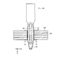
- FIG. 2 is a sectional view taken along line AA of FIG.
- FIG. 3 is a sectional view taken along line BB of FIG.
- FIG. 4 is a front view of the press-fit terminal of the embodiment.
- FIG. 5 is a sectional view taken along line CC of FIG.
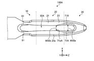
- FIG. 6 is a front view of the press-fit terminal of the first modified example.
- FIG. 7: is a front view of the press fit terminal of a 2nd modification.
- FIG. 8 is a front view of the press-fit terminal of the third modified example.
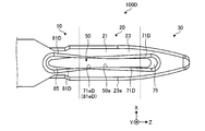
- FIG. 9 is a front view of the press-fit terminal of the fourth modified example.
- the Z axis is an axis parallel to the insertion direction of the press-fit terminal 100 into the through hole 201.
- the Y axis is an axis parallel to the penetrating direction of the through hole 50 of the press-fit terminal 100.
- the X axis is an axis that is orthogonal to both the Y axis and the Z axis.
- the direction along the X axis is described as the X direction
- the direction along the Y axis is described as the Y direction
- the direction along the Z axis is described as the Z direction.
- the X direction is the width direction of the press-fit terminal 100.
- the Y direction is the thickness direction of the press-fit terminal 100.
- the Y direction is the penetrating direction of the through hole 50.
- the Z direction is the longitudinal direction of the press-fit terminal 100.
- the Z direction is a direction orthogonal to the substrate 200. Of the Z directions, the direction (insertion direction) in which the press-fit terminal 100 moves when it is inserted into the through hole 201 is the +Z direction, and the direction opposite to the +Z direction is the ⁇ Z direction.
- FIG. 1 is a perspective view of a press-fit terminal and a board of the embodiment.
- FIG. 2 is a sectional view taken along line AA of FIG.
- FIG. 3 is a sectional view taken along line BB of FIG.
- FIG. 4 is a front view of the press-fit terminal of the embodiment.
- FIG. 5 is a sectional view taken along line CC of FIG.
- the press-fit terminal 100 is depicted as a front view.
- the broken line in FIG. 4 indicates the position of the surface of the substrate 200.
- the press-fit terminal 100 of the embodiment is attached to a through hole 201 provided on the board 200.
- the press-fit terminal 100 is press fitted into the through hole 201.
- the board 200 is a printed board using, for example, glass epoxy and is a multilayer board.
- the through holes 201 are holes that penetrate all the layers of the substrate 200.
- the substrate 200 is provided with a plurality of through holes 201.
- the plurality of through holes 201 are insulated from each other.
- Metal plating is applied to the inner wall and the periphery of the through hole 201. Examples of the metal include a copper alloy, but are not particularly limited.
- the board 200 includes a plurality of electronic components.
- the substrate 200 may be a glass polyimide substrate or a fluorine substrate instead of the glass epoxy substrate.
- the press-fit terminal 100 includes a contact portion 20, a tip portion 30, a base portion 10, a through hole 50, a first inclined portion 71, a thin portion 75, and a second inclined portion 81. , Is provided.
- the base portion 10, the contact portion 20, and the tip portion 30 are arranged in this order in the +Z direction.
- the base portion 10, the contact portion 20, the tip portion 30, the first inclined portion 71, the thin portion 75, and the second inclined portion 81 are integrally formed of metal. Examples of the metal include a copper alloy, but are not particularly limited.
- the press-fit terminal 100 is formed by pressing a metal plate material.
- the metal surface of the press-fit terminal 100 is subjected to base plating and surface layer plating.
- the base plating may be Ni or Sn based.
- the surface layer plating may be Sn-based or Au-based. It should be noted that there may be no surface plating and only surface layer plating.
- the contact portion 20 is arranged inside the through hole 201.
- the contact portion 20 contacts the inner wall of the through hole 201.
- the contact portion 20 presses the inner wall of the through hole 201 by elastic deformation.
- the contact portion 20 includes a main body portion 21 and a reduction portion 23.
- the main body portion 21 and the reduction portion 23 are arranged in this order in the +Z direction. That is, the reduction unit 23 is arranged in the +Z direction with respect to the main body unit 21.
- the length of the body portion 21 in the X direction is constant.
- the length of the reduction unit 23 in the X direction decreases toward the +Z direction.
- the outer peripheral surface of the reduction unit 23 is curved. In XZ plane view (when viewed from the Y direction), the outer edge of the reduction unit 23 draws an arc.
- the tip portion 30 is arranged outside the through hole 201.
- the tip portion 30 projects from the through hole 201 in the +Z direction.
- the tip portion 30 is arranged in the +Z direction with respect to the contact portion 20.
- the length of the tip portion 30 in the X direction becomes smaller in the +Z direction.
- the outer peripheral surface of the tip portion 30 is curved. In XZ plane view (when viewed from the Y direction), the outer edge of the tip portion 30 draws an arc.
- the base portion 10 when the press-fit terminal 100 is attached to the through hole 201, the base portion 10 is arranged outside the through hole 201. The base portion 10 projects from the through hole 201 in the ⁇ Z direction.
- the base portion 10 is arranged in the ⁇ Z direction with respect to the contact portion 20.
- the base portion 10 is arranged on the opposite side of the tip portion 30 with the contact portion 20 interposed therebetween.
- the base 10 is connected to an electronic component or the like as an object electrically connected to the substrate 200.
- the electronic component and the substrate 200 are electrically connected to each other via the base portion 10 and the contact portion 20.
- the through hole 50 penetrates the press-fit terminal 100 in the thickness direction.
- the through hole 50 is provided over the base portion 10, the contact portion 20, and the tip portion 30.
- the ⁇ Z direction end of the through hole 50 is arranged in the base 10.
- the end portion of the through hole 50 in the +Z direction is arranged at the tip portion 30.
- the length of the through hole 50 in the X direction is constant from the portion corresponding to the contact portion 20 to the portion corresponding to the tip portion 30.
- the length of the through hole 50 in the X direction increases from the portion corresponding to the contact portion 20 toward the portion corresponding to the base portion 10.
- the length of the through hole 50 in the X direction is smaller in the ⁇ Z direction at the portion corresponding to the base 10.
- the first inclined portion 71 is provided across the contact portion 20 and the tip portion 30.
- the first inclined portion 71 is arranged on the through hole 50 side of the contact portion 20 and the tip portion 30. That is, the first inclined portion 71 is arranged inside the contact portion 20 and the tip portion 30.
- the first inclined portion 71 faces the through hole 50. That is, the first inclined portion 71 is continuously formed on the outer periphery of the through hole 50.
- the thickness of the first inclined portion 71 in the Y direction becomes smaller as it approaches the through hole 50.
- the first inclined portion 71 includes an inclined surface that makes an angle with the XZ plane.
- the first inclined portion 71 includes a portion whose length in the X direction increases in the +Z direction. That is, in at least a part of the first inclined portion 71, the length in the X direction increases in the +Z direction.
- the ⁇ Z direction end portion 71 e of the first inclined portion 71 is arranged in the contact portion 20.
- the end portion 71e of the first inclined portion 71 is arranged in the +Z direction (on the tip portion 30 side) with respect to the end portion of the contact portion 20 on the base portion 10 side in the Z direction.
- the end portion 71e of the first inclined portion 71 is arranged in the ⁇ Z direction with respect to the ⁇ Z direction end portion 23e of the reduction portion 23.
- the position of the end portion 71e of the first inclined portion 71 in the Z direction is equal to the position of the bent portion 50e of the through hole 50 in the Z direction.
- the bent portion 50e is an end portion in the ⁇ Z direction of a portion where the width of the through hole 50 in the X direction is constant.
- the press-fit terminal 100 includes two first inclined portions 71.
- One first inclined portion 71 is arranged on one side in the X direction with respect to the through hole 50.
- the other first inclined portion 71 is arranged on the other side in the X direction with respect to the through hole 50. That is, the first inclined portion 71 is arranged on both sides in the X direction with respect to the through hole 50.
- the two first inclined portions 71 are connected to each other at a position in the +Z direction (position of the tip portion 30) with respect to the through hole 50.
- the thin portion 75 is arranged between the end portion of the through hole 50 in the +Z direction and the first inclined portion 71. That is, the thin portion 75 is arranged inside the first inclined portion 71. As shown in FIG. 5, the thickness T75 of the thin portion 75 in the Y direction is smaller than the thickness T30 of the tip portion 30 in the Y direction. The thickness T75 of the thin portion 75 is constant.
- the thin portion 75 has a surface parallel to the XZ plane.
- the second inclined portion 81 is provided across the contact portion 20 and the base portion 10.
- the second inclined portion 81 is arranged with a space in the Z direction with respect to the first inclined portion 71.
- the second inclined portion 81 is arranged on the side of the through hole 50 of the contact portion 20 and the base portion 10. That is, the second inclined portion 81 is arranged inside the contact portion 20 and the base portion 10.
- the second inclined portion 81 faces the through hole 50. That is, the second inclined portion 81 is continuously formed on the outer periphery of the through hole 50.
- the thickness of the second inclined portion 81 in the Y direction becomes smaller as it approaches the through hole 50.
- the second inclined portion 81 includes an inclined surface that makes an angle with the XZ plane.
- the second inclined portion 81 includes a portion whose length in the X direction increases toward the ⁇ Z direction. That is, in at least a part of the second inclined portion 81, the length in the X direction increases in the ⁇ Z direction.
- the +Z direction end 81e of the second inclined portion 81 is arranged in the ⁇ Z direction with respect to the contact portion 20. That is, the end portion 81e of the second inclined portion 81 is arranged on the base portion 10.
- the press-fit terminal 100 includes two second inclined portions 81.
- One second inclined portion 81 is arranged on one side in the X direction with respect to the through hole 50.
- the other second inclined portion 81 is arranged on the other side in the X direction with respect to the through hole 50. That is, the second inclined portion 81 is arranged on both sides in the X direction with respect to the through hole 50.
- the two second inclined portions 81 are connected at a position (the position of the base portion 10) in the ⁇ Z direction with respect to the through hole 50.
- the tip portion 30 is first inserted into the through hole 201. Then, the contact portion 20 reaches the through hole 201. With the contact portion 20 in contact with the through hole 201, the press-fit terminal 100 is press-fitted. Since the press-fit terminal 100 has the through hole 50, it can be easily elastically deformed at the time of press fitting. The contact portion 20 enters the through hole 201 while elastically deforming. When the contact portion 20 is inserted into the through hole 201, the press fitting ends. The press-fit terminal 100 is elastically deformed while being attached to the through hole 201. Since the contact portion 20 presses the inner wall of the through hole 201, friction occurs between the contact portion 20 and the inner wall of the through hole 201. As a result, the press-fit terminal 100 is held in the through hole 201.
- the two first inclined portions 71 do not necessarily have to be connected.
- the two second inclined portions 81 do not necessarily have to be connected.
- the press-fit terminal 100 does not need to include the second inclined portion 81.
- the press-fit terminal 100 does not have to include the thin portion 75.
- the press-fit terminal 100 includes the contact portion 20, the tip portion 30, the base portion 10, the through hole 50, and the first inclined portion 71.
- the contact portion 20 contacts the inner wall of the through hole 201 provided in the substrate 200.
- the tip portion 30 is arranged on the tip side with respect to the contact portion 20 in the insertion direction (+Z direction) into the through hole 201.
- the base portion 10 is arranged on the opposite side of the tip portion 30 with the contact portion 20 interposed therebetween.
- the through hole 50 is provided over the base portion 10, the contact portion 20, and the tip portion 30.
- the first inclined portion 71 is provided over the contact portion 20 and the tip portion 30 and is continuously arranged on the outer periphery of the through hole 50.
- the first inclined portion 71 is inclined toward the through hole 50.
- the length in the width direction (X direction) orthogonal to the insertion direction (+Z direction) and the penetration direction (Y direction) of the through hole 50 is at the tip of the tip portion 30. It is getting bigger and bigger.
- the press-fit terminal 100 of this embodiment includes the first inclined portion 71 as described above.
- the first inclined portion 71 reduces the second moment of area of the press-fit terminal 100 in the XY plane (second moment of area about the X axis and second moment of area about the Y axis).
- the press-fit terminal 100 can easily elastically deform on the side of the tip portion 30 when it is inserted into the through hole 201.
- the press-fit terminal 100 can be flexibly elastically deformed to reduce the force applied to the inner wall of the through hole 201 during insertion.
- the press-fit terminal 100 of the present embodiment can reduce the force applied to the through hole 201 at the time of insertion and can prevent the drop-out after insertion.
- the end portion 71e of the first inclined portion 71 on the base portion 10 side is arranged closer to the tip portion 30 side than the end portion of the contact portion 20 on the base portion 10 side. This improves the balance between the insertion force of the press-fit terminal 100 at the time of insertion into the through hole 201 and the holding force of the press-fit terminal 100 after being inserted into the through hole 201. Therefore, the press-fit terminal 100 of the present embodiment can further reduce the force applied to the through hole 201 at the time of insertion and can further suppress the dropout after insertion.
- the contact portion 20 includes a main body portion 21 and a reduction portion 23.
- the main body 21 has a constant length in the width direction (X direction).
- the reducing portion 23 is arranged on the side of the distal end portion 30 with respect to the main body portion 21, and has a length in the width direction (X direction) that decreases toward the distal end portion 30. This facilitates the work of inserting the press-fit terminal 100 into the through hole 201.
- the end portion 71e of the first inclined portion 71 on the base portion 10 side is arranged on the base portion 10 side with respect to the end portion 23e of the reduced portion 23 on the base portion 10 side. This improves the balance between the insertion force of the press-fit terminal 100 at the time of insertion into the through hole 201 and the holding force of the press-fit terminal 100 after being inserted into the through hole 201. Therefore, the press-fit terminal 100 of the present embodiment can further reduce the force applied to the through hole 201 at the time of insertion and can further suppress the dropout after insertion.
- the first inclined portions 71 are arranged on both sides of the through hole 50 in the width direction (X direction).
- the two first inclined portions 71 are connected by the tip portion 30. This makes it easier to adjust the rigidity of the press-fit terminal 100 when it is inserted into the through hole 201. Therefore, the press-fit terminal 100 of this embodiment can further reduce the force applied to the through hole 201 during insertion.
- the press-fit terminal 100 includes a thin portion 75 arranged between the end of the through hole 50 in the insertion direction (+Z direction) and the first inclined portion 71.
- the end of the thin portion 75 on the through hole 50 side ( ⁇ Z direction side) is continuously formed in an arc shape in a Y direction plan view so as not to be a starting point of a crack or the like during insertion.
- the thickness T75 of the thin portion 75 in the penetrating direction (Y direction) is smaller than the thickness T30 of the tip portion 30 in the penetrating direction (Y direction).
- the press-fit terminal 100 can both allow elastic deformation of the tip portion 30 at the time of insertion and simultaneously suppress plastic deformation of the elastic portion 35 (see FIG. 4 ). Therefore, the press-fit terminal 100 can suppress the buckling of the tip portion 30 when it is inserted into the through hole 201.
- the press-fit terminal 100 includes a second inclined portion 81 that is provided over the contact portion 20 and the base portion 10 and that is continuously arranged on the outer periphery of the through hole 50.
- the second inclined portion 81 is inclined toward the through hole 50.
- the length of the second inclined portion 81 in the width direction (X direction) increases in the direction ( ⁇ Z direction) opposite to the tip of the tip portion 30. Accordingly, the press-fit terminal 100 can be elastically deformed more easily when it is inserted into the through hole 201. Further, after the press-fit terminal 100 is inserted into the through hole 201, the second inclined portion 81 can increase the reaction force applied to the inner wall of the through hole 201 by the contact portion 20 of the press-fit terminal 100.
- the press-fit terminal 100 of the present embodiment can further reduce the force applied to the through hole 201 at the time of insertion and can further suppress the dropout after insertion.
- the second inclined portions 81 are arranged on both sides in the width direction (X direction) with respect to the through hole 50.
- the two second inclined portions 81 are connected by the base portion 10. This makes it easier to adjust the reaction force applied to the inner wall of the through hole 201 by the contact portion 20 of the press-fit terminal 100 after insertion. Therefore, the press-fit terminal 100 of this embodiment can further reduce the force applied to the through hole 201 during insertion.
- FIG. 6 is a front view of the press-fit terminal of the first modified example.
- the broken line in FIG. 6 indicates the position of the surface of the substrate 200.
- the same components as those described in the above-described embodiment are denoted by the same reference numerals, and overlapping description will be omitted.
- the press-fit terminal 100A of the first modified example includes a through hole 50A and a first inclined portion 71A.
- the length of the through hole 50A in the X direction changes from the portion corresponding to the contact portion 20 to the portion corresponding to the tip portion 30.
- the length W50a shown in FIG. 6 is greater than the length W50b.
- the length W50a is the maximum length in the X direction of the portion of the through hole 50A corresponding to the tip portion 30.
- the length W50b is the length in the X direction of the portion of the through hole 50A corresponding to the ⁇ Z direction end portion 71eA of the first inclined portion 71A.
- the first inclined portion 71A includes a portion whose length in the X direction increases in the +Z direction. That is, in at least a part of the first inclined portion 71A, the length in the X direction increases toward the +Z direction.
- the end portion 71eA of the first inclined portion 71A is arranged in the +Z direction with respect to the end portion 23e of the reduction portion 23.
- the press-fit terminal 100A includes two first inclined portions 71A.
- One first inclined portion 71A is arranged on one side in the X direction with respect to the through hole 50A.
- the other first inclined portion 71A is arranged on the other side in the X direction with respect to the through hole 50A. That is, the first inclined portion 71A is arranged on both sides in the X direction with respect to the through hole 50A.
- the two first inclined portions 71A are connected to each other at a position in the +Z direction with respect to the through hole 50A.
- the maximum length W50a in the width direction (X direction) of the portion of the through hole 50A corresponding to the tip portion 30 is the first of the through holes 50A. It is larger than the length W50b in the width direction (X direction) of the portion corresponding to the end portion 71eA on the base portion 10 side of the first inclined portion 71.
- the rigidity of the press-fit terminal 100A when it is inserted into the through hole 201 is more likely to decrease. Therefore, the press-fit terminal 100A of the first modified example can further reduce the force applied to the through hole 201 during insertion.
- FIG. 7 is a front view of the press fit terminal of a 2nd modification.
- the broken line in FIG. 7 indicates the position of the surface of the substrate 200.
- the same components as those described in the above-described embodiment are denoted by the same reference numerals, and overlapping description will be omitted.
- the press-fit terminal 100B of the second modified example includes a through hole 50B and a first inclined portion 71B.
- the first inclined portion 71B includes a portion whose length in the X direction increases toward the +Z direction. That is, in at least a part of the first inclined portion 71B, the length in the X direction increases toward the +Z direction.
- the ⁇ Z direction end 71eB of the first inclined portion 71B is arranged at the same position in the Z direction as the ⁇ Z direction end 23e of the contracting portion 23 of the contact portion 20.
- the press-fit terminal 100B includes two first inclined portions 71B.
- One first inclined portion 71B is arranged on one side in the X direction with respect to the through hole 50B.
- the other first inclined portion 71B is arranged on the other side in the X direction with respect to the through hole 50B. That is, the first inclined portion 71B is arranged on both sides of the through hole 50B in the X direction.
- the two first inclined portions 71B are connected at a position in the +Z direction with respect to the through hole 50B.
- the distance D71B is larger than the length W30.
- the distance D71B is the distance from the tip 50fB of the through hole 50B in the +Z direction to the tip 71fB of the first inclined portion 71B in the +Z direction.
- the length W30 is the minimum length of the tip portion 30 in the X direction.
- D71B is larger than the minimum length W30 of the tip portion 30 in the width direction (X direction).
- FIG. 8 is a front view of the press-fit terminal of the third modified example.
- the broken line in FIG. 8 indicates the position of the surface of the substrate 200.
- the same components as those described in the above-described embodiment are denoted by the same reference numerals, and overlapping description will be omitted.
- the press-fit terminal 100C of the third modified example includes a contact portion 20C, a through hole 50C, a first inclined portion 71C, and a thin portion 75C.
- the contact portion 20C includes a reduction portion 23C.
- the reduction unit 23C is arranged in the +Z direction with respect to the main body unit 21.
- the length of the reducing portion 23C in the X direction decreases in the +Z direction.
- the outer peripheral surface of the reduced portion 23C is planar. In XZ plane view (when viewed from the Y direction), the outer edge of the reduction unit 23C draws a straight line.
- the end portion 71eC of the first inclined portion 71C is arranged in the ⁇ Z direction with respect to the ⁇ Z direction end portion 23eC of the reduction portion 23C.
- the position of the end portion 71eC in the Z direction is equal to the position of the bent portion 50eC of the through hole 50C in the Z direction.
- the outer peripheral surface of the reduced portion 23C is flat. Therefore, when the press-fit terminal 100C is inserted into the through hole 201, the posture of the press-fit terminal 100C is stabilized.
- the press-fit terminal 100C can suppress tilting (inclination with respect to the Z axis) during insertion into the through hole 201.
- FIG. 9 is a front view of the press-fit terminal of the fourth modified example.
- the broken line in FIG. 9 indicates the position of the surface of the substrate 200.
- the same components as those described in the above-described embodiment are denoted by the same reference numerals, and overlapping description will be omitted.
- the press-fit terminal 100D of the fourth modified example includes a first inclined portion 71D, a second inclined portion 81D, and a thin portion 85.
- the ⁇ Z direction end portion 71eD of the first inclined portion 71D is connected to the +Z direction end portion 81eD of the second inclined portion 81D.
- the end portion 71eD of the first inclined portion 71D (the end portion 81eD of the second inclined portion 81D) is arranged in the contact portion 20.
- the end portion 71eD of the first inclined portion 71D is arranged in the +Z direction with respect to the ⁇ Z direction end portion of the contact portion 20.
- the end portion 71eD of the first inclined portion 71D is arranged in the ⁇ Z direction with respect to the ⁇ Z direction end portion 23e of the reduction portion 23.
- the end portion 71eD of the first inclined portion 71D is arranged at the same position as the bent portion 50e of the through hole 50 or in the ⁇ Z direction with respect to the bent portion 50e.
- the through hole 50 is surrounded by the first inclined portion 71D and the second inclined portion 81D over the entire circumference.
- the first sloped portion 71D and the second sloped portion 81D are formed continuously over the entire length of the outer circumference of the through hole 50.
- the thin portion 85 is arranged between the ⁇ Z direction end of the through hole 50 and the second inclined portion 81D. That is, the thin portion 85 is arranged inside the second inclined portion 81D.
- the thickness of the thin portion 85 in the Y direction is smaller than the thickness of the base 10 in the Y direction.
- the thin portion 85 has a constant thickness.
- the thin portion 85 has a surface parallel to the XZ plane.
- the end portion 71eD of the first inclined portion 71D on the base portion 10 side is connected to the end portion 81eD of the second inclined portion 81D on the tip portion 30 side. .. Accordingly, in the press-fit terminal 100D of the fourth modified example, it is possible to prevent the end portion 71eD of the first inclined portion 71D and the end portion 81eD of the second inclined portion 81D from becoming the starting points of cracks and the like. Further, it becomes easier to adjust the insertion force when inserting the press-fit terminal 100D into the through hole 201 and the holding force of the press-fit terminal 100D with respect to the through hole 201.
Landscapes
- Coupling Device And Connection With Printed Circuit (AREA)
Abstract
プレスフィット端子は、基板に設けられるスルーホールの内壁に接する接触部と、接触部に対してスルーホールへの挿入方向における先端側に配置される先端部と、接触部を挟んで先端部とは反対側に配置される基部と、基部、接触部及び先端部に亘って設けられる貫通孔と、接触部及び先端部に亘って設けられ且つ貫通孔の外周に連続して配置される第1傾斜部と、を備える。第1傾斜部は、貫通孔に向かって傾斜している。第1傾斜部の少なくとも一部において、挿入方向及び貫通方向に対して直交する幅方向における長さは、先端部の先端に向かって大きくなっている。
Description
本発明は、プレスフィット端子に関する。
電子機器の基板に設けられるスルーホールに保持されるプレスフィット端子が知られている。プレスフィット端子は、スルーホールに圧入され、スルーホールの内壁から受ける反力によって保持される。特許文献1にはプレスフィット端子の一例が記載されている。
1つの態様のプレスフィット端子は、基板に設けられるスルーホールの内壁に接する接触部と、前記接触部に対して前記スルーホールへの挿入方向における先端側に配置される先端部と、前記接触部を挟んで前記先端部とは反対側に配置される基部と、前記基部、前記接触部及び前記先端部に亘って設けられる貫通孔と、前記接触部及び前記先端部に亘って設けられ且つ前記貫通孔の外周に連続して配置される第1傾斜部と、を備え、前記第1傾斜部は、前記貫通孔に向かって傾斜しており、前記第1傾斜部の少なくとも一部において、前記挿入方向及び前記貫通孔の貫通方向に対して直交する幅方向における長さは、前記先端部の先端に向かって大きくなっている。
以下、本開示のプレスフィット端子の実施形態を図面に基づいて説明する。なお、この実施形態により発明が限定されるものではない。また、下記実施形態における構成要素には、当業者が置換可能かつ容易なもの、あるいは実質的に同一のものが含まれる。
以下の説明において、XYZ直交座標系が用いられる。Z軸は、プレスフィット端子100のスルーホール201への挿入方向と平行な軸である。Y軸は、プレスフィット端子100の貫通孔50の貫通方向と平行な軸である。X軸は、Y軸及びZ軸の両方に対して直交する軸である。X軸に沿う方向はX方向と記載され、Y軸に沿う方向はY方向と記載され、Z軸に沿う方向はZ方向と記載される。
X方向は、プレスフィット端子100の幅方向である。Y方向は、プレスフィット端子100の厚さ方向である。Y方向は、貫通孔50の貫通方向である。Z方向は、プレスフィット端子100の長手方向である。Z方向は、基板200に対して直交する方向である。Z方向のうちプレスフィット端子100がスルーホール201に挿入される時に移動する方向(挿入方向)を+Z方向とし、+Z方向の反対方向を-Z方向とする。
(実施形態)
図1は、実施形態のプレスフィット端子及び基板の斜視図である。図2は、図1のA-A断面図である。図3は、図2のB-B断面図である。図4は、実施形態のプレスフィット端子の正面図である。図5は、図4のC-C断面図である。なお、図2においてプレスフィット端子100は、正面図として描かれている。図4における破線は、基板200の表面の位置を示す。
図1は、実施形態のプレスフィット端子及び基板の斜視図である。図2は、図1のA-A断面図である。図3は、図2のB-B断面図である。図4は、実施形態のプレスフィット端子の正面図である。図5は、図4のC-C断面図である。なお、図2においてプレスフィット端子100は、正面図として描かれている。図4における破線は、基板200の表面の位置を示す。
図1に示すように、実施形態のプレスフィット端子100は、基板200に設けられるスルーホール201に取り付けられる。プレスフィット端子100は、スルーホール201に圧入される。基板200は、例えばガラスエポキシを使用したプリント基板であって、多層基板である。スルーホール201は、基板200の全ての層を貫通する穴である。基板200には、複数のスルーホール201が設けられる。複数のスルーホール201は、互いに絶縁されている。スルーホール201の内壁及び周辺には、金属のめっきが施される。金属としては、例えば銅合金が挙げられるが、特に限定されない。基板200は、複数の電子部品を備える。なお、基板200は、ガラスエポキシ基板の他に、ガラスポリイミド基板やフッ素基板であってもよい。
図4に示すように、プレスフィット端子100は、接触部20と、先端部30と、基部10と、貫通孔50と、第1傾斜部71と、薄肉部75と、第2傾斜部81と、を備える。+Z方向に向かって、基部10、接触部20、先端部30の順に配置される。基部10、接触部20、先端部30、第1傾斜部71、薄肉部75及び第2傾斜部81は、金属によって一体に形成される。金属としては、例えば銅合金が挙げられるが、特に限定されない。具体的には、プレスフィット端子100は、金属の板材にプレス加工を施すことによって形成される。プレスフィット端子100の金属表面には、下地めっき及び表層めっきが施される。下地めっきは、Ni又は、Sn系であってもよい。表層めっきは、Sn系又はAuであってもよい。なお、下地めっきがなく、表層めっきのみでもよい。
図2に示すように、プレスフィット端子100がスルーホール201に取り付けられた状態において、接触部20は、スルーホール201の内側に配置される。接触部20は、スルーホール201の内壁に接する。接触部20は、弾性変形によって、スルーホール201の内壁を押圧する。
図4に示すように、接触部20は、本体部21と、縮小部23と、を備える。+Z方向に向かって本体部21、縮小部23の順に配置される。すなわち、縮小部23は、本体部21に対して、+Z方向に配置される。本体部21のX方向の長さは、一定である。縮小部23のX方向の長さは、+Z方向に向かって小さくなっている。縮小部23の外周面は、曲面状である。XZ平面視において(Y方向から見た場合)、縮小部23の外縁は、円弧を描く。
図2に示すように、プレスフィット端子100がスルーホール201に取り付けられた状態において、先端部30は、スルーホール201の外側に配置される。先端部30は、スルーホール201から+Z方向に突出する。
図4に示すように、先端部30は、接触部20に対して+Z方向に配置される。先端部30のX方向の長さは、+Z方向に向かって小さくなっている。先端部30の外周面は、曲面状である。XZ平面視において(Y方向から見た場合)、先端部30の外縁は、円弧を描く。
図2に示すように、プレスフィット端子100がスルーホール201に取り付けられた状態において、基部10は、スルーホール201の外側に配置される。基部10は、スルーホール201から-Z方向に突出する。
図4に示すように、基部10は、接触部20に対して-Z方向に配置される。基部10は、接触部20を挟んで先端部30とは反対側に配置される。基部10は、基板200と電気的に接続される対象物としての電子部品等に接続される。基部10及び接触部20を介して、電子部品と基板200とが電気的に接続される。
図4に示すように、貫通孔50は、プレスフィット端子100を、厚さ方向に貫通している。貫通孔50は、基部10、接触部20及び先端部30に亘って設けられる。貫通孔50の-Z方向の端部は、基部10に配置される。貫通孔50の+Z方向の端部は、先端部30に配置される。貫通孔50のX方向の長さは、接触部20に対応する部分から先端部30に対応する部分にかけて一定である。貫通孔50のX方向の長さは、接触部20に対応する部分から基部10に対応する部分に向かって大きくなっている。貫通孔50のX方向の長さは、基部10に対応する部分において、-Z方向に向かって小さくなっている。
図4に示すように、第1傾斜部71は、接触部20及び先端部30に亘って設けられる。第1傾斜部71は、接触部20及び先端部30の貫通孔50側に配置される。すなわち、第1傾斜部71は、接触部20及び先端部30の内側に配置される。第1傾斜部71は、貫通孔50に面する。すなわち、第1傾斜部71は、貫通孔50の外周に連続して形成される。図5に示すように、第1傾斜部71のY方向の厚さは、貫通孔50に近付くにしたがって小さくなっている。第1傾斜部71は、XZ平面に対して角度をなす傾斜面を備える。
図4に示すように、第1傾斜部71は、X方向の長さが+Z方向に向かって大きくなる部分を備える。すなわち、第1傾斜部71の少なくとも一部において、X方向の長さは、+Z方向に向かって大きくなっている。第1傾斜部71の-Z方向の端部71eは、接触部20に配置される。第1傾斜部71の端部71eは、Z方向における接触部20の基部10側の端部に対して、+Z方向(先端部30側)に配置される。第1傾斜部71の端部71eは、縮小部23の-Z方向の端部23eに対して、-Z方向に配置される。第1傾斜部71の端部71eのZ方向の位置は、貫通孔50の屈曲部50eのZ方向の位置と等しい。屈曲部50eは、貫通孔50のX方向の幅が一定である部分の-Z方向の端部である。
図4に示すように、プレスフィット端子100は、2つの第1傾斜部71を備える。1つの第1傾斜部71は、貫通孔50に対してX方向の一方側に配置される。もう1つの第1傾斜部71は、貫通孔50に対してX方向の他方側に配置される。すなわち、第1傾斜部71は、貫通孔50に対してX方向の両側に配置される。2つの第1傾斜部71は、貫通孔50よりも+Z方向の位置(先端部30の位置)で繋がっている。
図4に示すように、薄肉部75は、貫通孔50の+Z方向の端部と第1傾斜部71との間に配置される。すなわち、薄肉部75は、第1傾斜部71の内側に配置される。図5に示すように、薄肉部75のY方向の厚さT75は、先端部30のY方向の厚さT30よりも小さい。薄肉部75の厚さT75は、一定である。薄肉部75は、XZ平面と平行な表面を備える。
図4に示すように、第2傾斜部81は、接触部20及び基部10に亘って設けられる。第2傾斜部81は、第1傾斜部71に対してZ方向に間隔を空けて配置される。第2傾斜部81は、接触部20及び基部10の貫通孔50側に配置される。すなわち、第2傾斜部81は、接触部20及び基部10の内側に配置される。第2傾斜部81は、貫通孔50に面する。すなわち、第2傾斜部81は、貫通孔50の外周に連続して形成される。第2傾斜部81のY方向の厚さは、貫通孔50に近付くにしたがって小さくなっている。第2傾斜部81は、XZ平面に対して角度をなす傾斜面を備える。
図4に示すように、第2傾斜部81は、X方向の長さが-Z方向に向かって大きくなる部分を備える。すなわち、第2傾斜部81の少なくとも一部において、X方向の長さは、-Z方向に向かって大きくなっている。第2傾斜部81の+Z方向の端部81eは、接触部20に対して、-Z方向に配置される。すなわち、第2傾斜部81の端部81eは、基部10に配置される。
図4に示すように、プレスフィット端子100は、2つの第2傾斜部81を備える。1つの第2傾斜部81は、貫通孔50に対してX方向の一方側に配置される。もう1つの第2傾斜部81は、貫通孔50に対してX方向の他方側に配置される。すなわち、第2傾斜部81は、貫通孔50に対してX方向の両側に配置される。2つの第2傾斜部81は、貫通孔50よりも-Z方向の位置(基部10の位置)で繋がっている。
プレスフィット端子100がスルーホール201に取り付けられる時、まず先端部30がスルーホール201に挿入される。その後、接触部20がスルーホール201に達する。接触部20がスルーホール201に接した状態で、プレスフィット端子100が圧入される。プレスフィット端子100は、貫通孔50を備えることによって、圧入時に容易に弾性変形できる。接触部20は、弾性変形しながらスルーホール201に進入する。接触部20がスルーホール201に挿入されると、圧入が終了する。プレスフィット端子100は、スルーホール201に取り付けられた状態で弾性変形している。接触部20がスルーホール201の内壁を押圧するので、接触部20とスルーホール201の内壁との間には摩擦が生じる。これにより、プレスフィット端子100がスルーホール201に対して保持される。
なお、2つの第1傾斜部71は、必ずしも繋がっていなくてもよい。2つの第2傾斜部81は、必ずしも繋がっていなくてもよい。また、プレスフィット端子100は、第2傾斜部81を備えていなくてもよい。プレスフィット端子100は、薄肉部75を備えていなくてもよい。
以上で説明したように、プレスフィット端子100は、接触部20と、先端部30と、基部10と、貫通孔50と、第1傾斜部71と、を備える。接触部20は、基板200に設けられるスルーホール201の内壁に接する。先端部30は、接触部20に対して、スルーホール201への挿入方向(+Z方向)における先端側に配置される。基部10は、接触部20を挟んで先端部30とは反対側に配置される。貫通孔50は、基部10、接触部20及び先端部30に亘って設けられる。第1傾斜部71は、接触部20及び先端部30に亘って設けられ且つ貫通孔50の外周に連続して配置される。第1傾斜部71は、貫通孔50に向かって傾斜している。第1傾斜部71の少なくとも一部において、挿入方向(+Z方向)及び貫通孔50の貫通方向(Y方向)に対して直交する幅方向(X方向)における長さは、先端部30の先端に向かって大きくなっている。
例えば特許文献1に記載されるようなプレスフィット端子をスルーホールに挿入する時には、スルーホールの内壁に大きな力が加わることがある。プレスフィット端子がスルーホールの内壁に加える力によって、基板の層の間が剥離し、白化が生じる可能性がある。これにより、隣接するスルーホール間の実質的な距離が小さくなるため、隣接するスルーホール間の絶縁抵抗が低くなる。絶縁不良を抑制するため、プレスフィット端子をスルーホールに挿入する時にスルーホールに加わる力が低減されることが望ましい。一方、プレスフィット端子がスルーホールに挿入された後においては、プレスフィット端子がスルーホールから容易に脱落しないことが求められる。
これに対して、本実施形態のプレスフィット端子100は、上述したように第1傾斜部71を備える。第1傾斜部71によって、プレスフィット端子100のXY平面における断面二次モーメント(X軸に関する断面二次モーメント、及びY軸に関する断面二次モーメント)が小さくなる。本実施形態では、先端部30側に向けて第1傾斜部71が大きくなっていることで、先端部30のXY平面における断面二次モーメントを小さくすることができる。このため、プレスフィット端子100は、スルーホール201に挿入される時に先端部30側が容易に弾性変形できる。プレスフィット端子100は、柔軟に弾性変形することによって、挿入時にスルーホール201の内壁に与える力を低減できる。その結果、基板200の白化が抑制され、隣接するスルーホール201間の絶縁抵抗が保持される。一方、第1傾斜部71の少なくとも一部において、幅方向(X方向)における長さが先端部30の先端に向かって大きくなっている。このため、プレスフィット端子100がスルーホール201にある程度挿入されてからは、プレスフィット端子100の剛性が高くなる。プレスフィット端子100がスルーホール201に挿入された後において、プレスフィット端子100の弾性変形が抑制される。このため、プレスフィット端子100が基板200に保持される。したがって、本実施形態のプレスフィット端子100は、挿入時においてスルーホール201に与える力を低減でき且つ挿入後における脱落を抑制できる。
プレスフィット端子100において、第1傾斜部71の基部10側の端部71eは、接触部20の基部10側の端部よりも先端部30側に配置される。これにより、スルーホール201への挿入時におけるプレスフィット端子100の挿入力と、スルーホール201に挿入された後のプレスフィット端子100の保持力とのバランスが向上する。したがって、本実施形態のプレスフィット端子100は、挿入時においてスルーホール201に与える力をより低減でき且つ挿入後における脱落をより抑制できる。
プレスフィット端子100において、接触部20は、本体部21と、縮小部23と、を備える。本体部21は、幅方向(X方向)の長さが一定である。縮小部23は、本体部21に対して先端部30側に配置され、且つ幅方向(X方向)の長さが先端部30に向かって小さくなっている。これにより、プレスフィット端子100をスルーホール201に挿入する作業が容易になる。
プレスフィット端子100において、第1傾斜部71の基部10側の端部71eは、縮小部23の基部10側の端部23eに対して、基部10側に配置される。これにより、スルーホール201への挿入時におけるプレスフィット端子100の挿入力と、スルーホール201に挿入された後のプレスフィット端子100の保持力とのバランスが向上する。したがって、本実施形態のプレスフィット端子100は、挿入時においてスルーホール201に与える力をより低減でき且つ挿入後における脱落をより抑制できる。
プレスフィット端子100において、第1傾斜部71は、貫通孔50に対して幅方向(X方向)の両側に配置される。2つの第1傾斜部71は、先端部30で繋がっている。これにより、スルーホール201への挿入時におけるプレスフィット端子100の剛性をより調整しやすくなる。したがって、本実施形態のプレスフィット端子100は、挿入時においてスルーホール201に与える力をより低減できる。
プレスフィット端子100は、貫通孔50の挿入方向(+Z方向)の端部と第1傾斜部71との間に配置される薄肉部75を備える。薄肉部75の貫通孔50側(-Z方向側)の端部は、挿入時におけるクラック等の起点とならないよう、Y方向平面視において円弧状に連続して形成される。貫通方向(Y方向)における薄肉部75の厚さT75は、先端部30の貫通方向(Y方向)における厚さT30よりも小さい。これにより、プレスフィット端子100は、挿入時における先端部30の弾性変形を許容するとともに、弾性部35(図4参照)の塑性変形抑制の両立をはかることができる。したがって、プレスフィット端子100は、スルーホール201への挿入時における先端部30の座屈を抑制できる。
プレスフィット端子100は、接触部20及び基部10に亘って設けられ且つ貫通孔50の外周に連続して配置される第2傾斜部81を備える。第2傾斜部81は、貫通孔50に向かって傾斜している。幅方向(X方向)における第2傾斜部81の長さは、先端部30の先端とは反対方向(-Z方向)に向かって大きくなっている。これにより、プレスフィット端子100は、スルーホール201に挿入される時により容易に弾性変形できる。また、プレスフィット端子100がスルーホール201に挿入されてからは、第2傾斜部81によりプレスフィット端子100の接触部20がスルーホール201の内壁に与える反力を大きくできる。すなわち、スルーホール201へ挿入後のプレスフィット端子100の保持力を向上できる。本実施形態のプレスフィット端子100は、挿入時においてスルーホール201に与える力をより低減でき且つ挿入後における脱落をより抑制できる。
プレスフィット端子100において、第2傾斜部81は、貫通孔50に対して幅方向(X方向)の両側に配置される。2つの第2傾斜部81は、基部10で繋がっている。これにより、挿入後におけるプレスフィット端子100の接触部20がスルーホール201の内壁に与える反力をより調整しやすくなる。したがって、本実施形態のプレスフィット端子100は、挿入時においてスルーホール201に与える力をより低減できる。
本開示の実施形態は、発明の要旨及び範囲を逸脱しない範囲で変更することができる。さらに、本開示の実施形態及びその変形例は、適宜組み合わせることができる。例えば、上記の実施形態は、以下のように変形してもよい。
(第1変形例)
図6は、第1変形例のプレスフィット端子の正面図である。図6における破線は、基板200の表面の位置を示す。なお、上述した実施形態で説明したものと同じ構成要素には同一の符号を付して重複する説明は省略する。
図6は、第1変形例のプレスフィット端子の正面図である。図6における破線は、基板200の表面の位置を示す。なお、上述した実施形態で説明したものと同じ構成要素には同一の符号を付して重複する説明は省略する。
図6に示すように、第1変形例のプレスフィット端子100Aは、貫通孔50Aと第1傾斜部71Aと、を備える。貫通孔50AのX方向の長さは、接触部20に対応する部分から先端部30に対応する部分にかけて変化している。図6に示す長さW50aは、長さW50bよりも大きい。長さW50aは、貫通孔50Aのうち先端部30に対応する部分のX方向における最大の長さである。長さW50bは、貫通孔50Aのうち第1傾斜部71Aの-Z方向の端部71eAに対応する部分のX方向における長さである。
図6に示すように、第1傾斜部71Aは、X方向の長さが+Z方向に向かって大きくなる部分を備える。すなわち、第1傾斜部71Aの少なくとも一部において、X方向の長さは、+Z方向に向かって大きくなっている。第1傾斜部71Aの端部71eAは、縮小部23の端部23eに対して、+Z方向に配置される。
図6に示すように、プレスフィット端子100Aは、2つの第1傾斜部71Aを備える。1つの第1傾斜部71Aは、貫通孔50Aに対してX方向の一方側に配置される。もう1つの第1傾斜部71Aは、貫通孔50Aに対してX方向の他方側に配置される。すなわち、第1傾斜部71Aは、貫通孔50Aに対してX方向の両側に配置される。2つの第1傾斜部71Aは、貫通孔50Aよりも+Z方向の位置で繋がっている。
上述したように、第1変形例のプレスフィット端子100Aにおいては、貫通孔50Aのうち先端部30に対応する部分の幅方向(X方向)における最大の長さW50aは、貫通孔50Aのうち第1傾斜部71の基部10側の端部71eAに対応する部分の幅方向(X方向)における長さW50bよりも大きい。これにより、スルーホール201への挿入時におけるプレスフィット端子100Aの剛性がより低下しやすくなる。したがって、第1変形例のプレスフィット端子100Aは、挿入時においてスルーホール201に与える力をより低減できる。
(第2変形例)
図7は、第2変形例のプレスフィット端子の正面図である。図7における破線は、基板200の表面の位置を示す。なお、上述した実施形態で説明したものと同じ構成要素には同一の符号を付して重複する説明は省略する。
図7は、第2変形例のプレスフィット端子の正面図である。図7における破線は、基板200の表面の位置を示す。なお、上述した実施形態で説明したものと同じ構成要素には同一の符号を付して重複する説明は省略する。
図7に示すように、第2変形例のプレスフィット端子100Bは、貫通孔50Bと、第1傾斜部71Bと、を備える。第1傾斜部71Bは、X方向の長さが+Z方向に向かって大きくなる部分を備える。すなわち、第1傾斜部71Bの少なくとも一部において、X方向の長さは、+Z方向に向かって大きくなっている。第1傾斜部71Bの-Z方向の端部71eBは、接触部20の縮小部23の-Z方向の端部23eと、Z方向において同じ位置に配置される。
図7に示すように、プレスフィット端子100Bは、2つの第1傾斜部71Bを備える。1つの第1傾斜部71Bは、貫通孔50Bに対してX方向の一方側に配置される。もう1つの第1傾斜部71Bは、貫通孔50Bに対してX方向の他方側に配置される。すなわち、第1傾斜部71Bは、貫通孔50Bに対してX方向の両側に配置される。2つの第1傾斜部71Bは、貫通孔50Bよりも+Z方向の位置で繋がっている。
図7に示すように、距離D71Bは、長さW30よりも大きい。距離D71Bは、貫通孔50Bの+Z方向における先端50fBから、第1傾斜部71Bの+Z方向における先端71fBまでの距離である。長さW30は、X方向における先端部30の最小の長さである。
上述したように、第2変形例のプレスフィット端子100Bにおいては、貫通孔50Bの挿入方向(+Z方向)における先端50fBから、第1傾斜部71Bの挿入方向(+Z方向)における先端71fBまでの距離D71Bは、幅方向(X方向)における先端部30の最小の長さW30よりも大きい。これにより、スルーホール201への挿入時におけるプレスフィット端子100Bの剛性がより低下しやすくなる。したがって、第2変形例のプレスフィット端子100Bは、挿入時においてスルーホール201に与える力をより低減できる。
(第3変形例)
図8は、第3変形例のプレスフィット端子の正面図である。図8における破線は、基板200の表面の位置を示す。なお、上述した実施形態で説明したものと同じ構成要素には同一の符号を付して重複する説明は省略する。
図8は、第3変形例のプレスフィット端子の正面図である。図8における破線は、基板200の表面の位置を示す。なお、上述した実施形態で説明したものと同じ構成要素には同一の符号を付して重複する説明は省略する。
図8に示すように、第3変形例のプレスフィット端子100Cは、接触部20Cと、貫通孔50Cと、第1傾斜部71Cと、薄肉部75Cと、を備える。接触部20Cは、縮小部23Cを備える。縮小部23Cは、本体部21に対して、+Z方向に配置される。縮小部23CのX方向の長さは、+Z方向に向かって小さくなっている。縮小部23Cの外周面は、平面状である。XZ平面視において(Y方向から見た場合)、縮小部23Cの外縁は、直線を描く。
第1傾斜部71Cの端部71eCは、縮小部23Cの-Z方向の端部23eCに対して、-Z方向に配置される。端部71eCのZ方向の位置は、貫通孔50Cの屈曲部50eCのZ方向の位置と等しい。
上述したように、第3変形例のプレスフィット端子100Cにおいては、縮小部23Cの外周面は、平面状である。これにより、プレスフィット端子100Cがスルーホール201に挿入される時に、プレスフィット端子100Cの姿勢が安定する。プレスフィット端子100Cは、スルーホール201への挿入時の倒れ(Z軸に対する傾斜)を抑制できる。
(第4変形例)
図9は、第4変形例のプレスフィット端子の正面図である。図9における破線は、基板200の表面の位置を示す。なお、上述した実施形態で説明したものと同じ構成要素には同一の符号を付して重複する説明は省略する。
図9は、第4変形例のプレスフィット端子の正面図である。図9における破線は、基板200の表面の位置を示す。なお、上述した実施形態で説明したものと同じ構成要素には同一の符号を付して重複する説明は省略する。
図9に示すように、第4変形例のプレスフィット端子100Dは、第1傾斜部71Dと、第2傾斜部81Dと、薄肉部85と、を備える。第1傾斜部71Dの-Z方向の端部71eDは、第2傾斜部81Dの+Z方向の端部81eDと繋がっている。第1傾斜部71Dの端部71eD(第2傾斜部81Dの端部81eD)は、接触部20に配置される。第1傾斜部71Dの端部71eDは、接触部20の-Z方向の端部に対して、+Z方向に配置される。第1傾斜部71Dの端部71eDは、縮小部23の-Z方向の端部23eに対して、-Z方向に配置される。第1傾斜部71Dの端部71eDは、貫通孔50の屈曲部50eと同一の位置、又は屈曲部50eに対して-Z方向に配置される。貫通孔50が、全周に亘って、第1傾斜部71D及び第2傾斜部81Dに囲まれる。第1傾斜部71D及び第2傾斜部81Dは、貫通孔50の外周の全長に亘って連続して形成される。
図9に示すように、薄肉部85は、貫通孔50の-Z方向の端部と第2傾斜部81Dとの間に配置される。すなわち、薄肉部85は、第2傾斜部81Dの内側に配置される。薄肉部85のY方向の厚さは、基部10のY方向の厚さよりも小さい。薄肉部85の厚さは、一定である。薄肉部85は、XZ平面と平行な表面を備える。
上述したように、第4変形例のプレスフィット端子100Dにおいては、第1傾斜部71Dの基部10側の端部71eDは、第2傾斜部81Dの先端部30側の端部81eDと繋がっている。これにより、第4変形例のプレスフィット端子100Dは、第1傾斜部71Dの端部71eD及び第2傾斜部81Dの端部81eDがクラック等の起点となることを抑制できる。さらに、プレスフィット端子100Dをスルーホール201に挿入する際の挿入力及び、スルーホール201に対するプレスフィット端子100Dの保持力をより調整しやすくなる。
10 基部
20、20C 接触部
21 本体部
23、23C 縮小部
23e、23eC 端部
30 先端部
50、50A、50B、50C 貫通孔
50e、50eC 屈曲部
50fB 先端
71、71A、71B、71C、71D 第1傾斜部
71e、71eA、71eB、71eC、71eD 端部
71fB 先端
75、75C 薄肉部
81、81D 第2傾斜部
81e、81eD 端部
85 薄肉部
100、100A、100B、100C、100D プレスフィット端子
200 基板
201 スルーホール
20、20C 接触部
21 本体部
23、23C 縮小部
23e、23eC 端部
30 先端部
50、50A、50B、50C 貫通孔
50e、50eC 屈曲部
50fB 先端
71、71A、71B、71C、71D 第1傾斜部
71e、71eA、71eB、71eC、71eD 端部
71fB 先端
75、75C 薄肉部
81、81D 第2傾斜部
81e、81eD 端部
85 薄肉部
100、100A、100B、100C、100D プレスフィット端子
200 基板
201 スルーホール
Claims (12)
- 基板に設けられるスルーホールの内壁に接する接触部と、
前記接触部に対して前記スルーホールへの挿入方向における先端側に配置される先端部と、
前記接触部を挟んで前記先端部とは反対側に配置される基部と、
前記基部、前記接触部及び前記先端部に亘って設けられる貫通孔と、
前記接触部及び前記先端部に亘って設けられ且つ前記貫通孔の外周に連続して配置される第1傾斜部と、
を備え、
前記第1傾斜部は、前記貫通孔に向かって傾斜しており、
前記第1傾斜部の少なくとも一部において、前記挿入方向及び前記貫通孔の貫通方向に対して直交する幅方向における長さは、前記先端部の先端に向かって大きくなっている
プレスフィット端子。 - 前記第1傾斜部の前記基部側の端部は、前記接触部の前記基部側の端部よりも前記先端部側に配置される
請求項1に記載のプレスフィット端子。 - 前記接触部は、
前記幅方向の長さが一定である本体部と、
前記本体部に対して前記先端部側に配置され、且つ前記幅方向の長さが前記先端部に向かって小さくなっている縮小部と、
を備える請求項1又は2に記載のプレスフィット端子。 - 前記第1傾斜部の前記基部側の端部は、前記縮小部の前記基部側の端部に対して、前記基部側に配置される
請求項3に記載のプレスフィット端子。 - 前記縮小部の外周面は、平面状である
請求項3又は4に記載のプレスフィット端子。 - 前記第1傾斜部は、前記貫通孔に対して前記幅方向の両側に配置され、
2つの前記第1傾斜部は、前記先端部で繋がっている
請求項1から5のいずれか1項に記載のプレスフィット端子。 - 前記貫通孔の前記挿入方向の端部と前記第1傾斜部との間に配置される薄肉部を備え、
前記貫通方向における前記薄肉部の厚さは、前記先端部の前記貫通方向における厚さよりも小さい
請求項1から6のいずれか1項に記載のプレスフィット端子。 - 前記貫通孔の前記挿入方向における先端から、前記第1傾斜部の前記挿入方向における先端までの距離は、前記幅方向における前記先端部の最小の長さよりも大きい
請求項6又は7に記載のプレスフィット端子。 - 前記接触部及び前記基部に亘って設けられ且つ前記貫通孔の外周に連続して配置される第2傾斜部を備え、
前記第2傾斜部は、前記貫通孔に向かって傾斜しており、
前記幅方向における前記第2傾斜部の長さは、前記先端部の先端とは反対方向に向かって大きくなっている
請求項1から8のいずれか1項に記載のプレスフィット端子。 - 前記第2傾斜部は、前記貫通孔に対して前記幅方向の両側に配置され、
2つの前記第2傾斜部は、前記基部で繋がっている
請求項9に記載のプレスフィット端子。 - 前記第1傾斜部の前記基部側の端部は、前記第2傾斜部の前記先端部側の端部と繋がっている
請求項9又は10に記載のプレスフィット端子。 - 前記貫通孔のうち前記先端部に対応する部分の前記幅方向における最大の長さは、前記貫通孔のうち前記第1傾斜部の前記基部側の端部に対応する部分の前記幅方向における長さよりも大きい
請求項1から11のいずれか1項に記載のプレスフィット端子。
Priority Applications (1)
| Application Number | Priority Date | Filing Date | Title |
|---|---|---|---|
| US17/425,920 US11646516B2 (en) | 2019-01-29 | 2020-01-29 | Press-fit terminal |
Applications Claiming Priority (2)
| Application Number | Priority Date | Filing Date | Title |
|---|---|---|---|
| JP2019-012814 | 2019-01-29 | ||
| JP2019012814A JP7084331B2 (ja) | 2019-01-29 | 2019-01-29 | プレスフィット端子 |
Publications (1)
| Publication Number | Publication Date |
|---|---|
| WO2020158827A1 true WO2020158827A1 (ja) | 2020-08-06 |
Family
ID=71840146
Family Applications (1)
| Application Number | Title | Priority Date | Filing Date |
|---|---|---|---|
| PCT/JP2020/003267 Ceased WO2020158827A1 (ja) | 2019-01-29 | 2020-01-29 | プレスフィット端子 |
Country Status (3)
| Country | Link |
|---|---|
| US (1) | US11646516B2 (ja) |
| JP (1) | JP7084331B2 (ja) |
| WO (1) | WO2020158827A1 (ja) |
Cited By (1)
| Publication number | Priority date | Publication date | Assignee | Title |
|---|---|---|---|---|
| WO2022069242A1 (de) * | 2020-09-29 | 2022-04-07 | Suba Holding Gmbh + Co. Kg | Einpresskontakt und verfahren zu seiner herstellung |
Families Citing this family (1)
| Publication number | Priority date | Publication date | Assignee | Title |
|---|---|---|---|---|
| JP7205714B2 (ja) * | 2018-12-28 | 2023-01-17 | 株式会社オートネットワーク技術研究所 | プレスフィット端子 |
Citations (8)
| Publication number | Priority date | Publication date | Assignee | Title |
|---|---|---|---|---|
| JPS6290883A (ja) * | 1985-06-13 | 1987-04-25 | ヒロセ電機株式会社 | 電気接触ピンの製造方法 |
| DE3630629A1 (de) * | 1986-09-09 | 1988-03-17 | Inovan Stroebe | Einpresskontakt |
| US4793817A (en) * | 1985-02-27 | 1988-12-27 | Karl Neumayer, Erzeugung Und Vertreib Von Kabeln, Drahten Isolierten Leitungen Und Elektromaterial Gesellschaft Mit Beschrankter Haftung | Contact pin |
| JP2005228710A (ja) * | 2004-02-16 | 2005-08-25 | Auto Network Gijutsu Kenkyusho:Kk | プレスフィット端子およびプレスフィット端子の製造方法 |
| JP2010501993A (ja) * | 2006-08-30 | 2010-01-21 | ローベルト ボツシユ ゲゼルシヤフト ミツト ベシユレンクテル ハフツング | 押し込みピン |
| DE102010024526A1 (de) * | 2010-06-21 | 2011-12-22 | Schroeder + Bauer Gmbh + Co. Kg | Einpresskontakt |
| WO2015029566A1 (ja) * | 2013-08-27 | 2015-03-05 | 日本圧着端子製造株式会社 | プレスフィット端子及びこれを用いたコネクタ並びにプレスフィット端子連続体、プレスフィット端子連続体巻き付け体 |
| WO2018220927A1 (ja) * | 2017-05-31 | 2018-12-06 | アイシン精機株式会社 | プレスフィット端子 |
Family Cites Families (8)
| Publication number | Priority date | Publication date | Assignee | Title |
|---|---|---|---|---|
| US6592382B2 (en) * | 2001-12-17 | 2003-07-15 | Woody Wurster | Simplified board connector |
| DE102004015431A1 (de) * | 2004-03-30 | 2005-10-20 | Conti Temic Microelectronic | Kontaktelement zum Einpressen in ein Loch einer Leiterplatte |
| JP5761218B2 (ja) * | 2013-01-30 | 2015-08-12 | 株式会社デンソー | プレスフィットピン、接続構造、及び電子装置 |
| JP6447333B2 (ja) | 2015-04-14 | 2019-01-09 | 株式会社オートネットワーク技術研究所 | 基板用コネクタ |
| US10998675B2 (en) * | 2016-08-22 | 2021-05-04 | Interplex Industries, Inc. | Electrical connector |
| JP7043751B2 (ja) * | 2016-10-12 | 2022-03-30 | 株式会社オートネットワーク技術研究所 | プレスフィット端子 |
| CN207925708U (zh) * | 2018-03-08 | 2018-09-28 | 富士康(昆山)电脑接插件有限公司 | 电连接器端子 |
| US11647591B2 (en) * | 2021-06-10 | 2023-05-09 | International Business Machines Corporation | Compliant pin surface mount technology pad for rework |
-
2019
- 2019-01-29 JP JP2019012814A patent/JP7084331B2/ja active Active
-
2020
- 2020-01-29 WO PCT/JP2020/003267 patent/WO2020158827A1/ja not_active Ceased
- 2020-01-29 US US17/425,920 patent/US11646516B2/en active Active
Patent Citations (8)
| Publication number | Priority date | Publication date | Assignee | Title |
|---|---|---|---|---|
| US4793817A (en) * | 1985-02-27 | 1988-12-27 | Karl Neumayer, Erzeugung Und Vertreib Von Kabeln, Drahten Isolierten Leitungen Und Elektromaterial Gesellschaft Mit Beschrankter Haftung | Contact pin |
| JPS6290883A (ja) * | 1985-06-13 | 1987-04-25 | ヒロセ電機株式会社 | 電気接触ピンの製造方法 |
| DE3630629A1 (de) * | 1986-09-09 | 1988-03-17 | Inovan Stroebe | Einpresskontakt |
| JP2005228710A (ja) * | 2004-02-16 | 2005-08-25 | Auto Network Gijutsu Kenkyusho:Kk | プレスフィット端子およびプレスフィット端子の製造方法 |
| JP2010501993A (ja) * | 2006-08-30 | 2010-01-21 | ローベルト ボツシユ ゲゼルシヤフト ミツト ベシユレンクテル ハフツング | 押し込みピン |
| DE102010024526A1 (de) * | 2010-06-21 | 2011-12-22 | Schroeder + Bauer Gmbh + Co. Kg | Einpresskontakt |
| WO2015029566A1 (ja) * | 2013-08-27 | 2015-03-05 | 日本圧着端子製造株式会社 | プレスフィット端子及びこれを用いたコネクタ並びにプレスフィット端子連続体、プレスフィット端子連続体巻き付け体 |
| WO2018220927A1 (ja) * | 2017-05-31 | 2018-12-06 | アイシン精機株式会社 | プレスフィット端子 |
Cited By (1)
| Publication number | Priority date | Publication date | Assignee | Title |
|---|---|---|---|---|
| WO2022069242A1 (de) * | 2020-09-29 | 2022-04-07 | Suba Holding Gmbh + Co. Kg | Einpresskontakt und verfahren zu seiner herstellung |
Also Published As
| Publication number | Publication date |
|---|---|
| US20220166156A1 (en) | 2022-05-26 |
| JP7084331B2 (ja) | 2022-06-14 |
| JP2020123431A (ja) | 2020-08-13 |
| US11646516B2 (en) | 2023-05-09 |
Similar Documents
| Publication | Publication Date | Title |
|---|---|---|
| US8771028B2 (en) | Connection structure for connecting a terminal fitting and a circuit board | |
| US10978816B2 (en) | Press-fit terminal and terminal-attached substrate | |
| CN109792113B (zh) | 压配合端子 | |
| US10680373B2 (en) | Electrical contact of electrical connector | |
| KR20150036695A (ko) | 도전성 클립 | |
| WO2020158827A1 (ja) | プレスフィット端子 | |
| WO2010021286A1 (ja) | 接続端子、コネクタ、ソケットおよび半導体パッケージ | |
| CN108780961B (zh) | 接触件 | |
| US11381013B2 (en) | Electrical connector | |
| US9570827B2 (en) | Contact member | |
| US9887480B2 (en) | Contact including deformation preventer for preventing deformation of connector support | |
| US11088484B2 (en) | Contact member | |
| JP2021093345A (ja) | プレスフィット端子、プレスフィット端子付基板及び機器 | |
| JP4532462B2 (ja) | プレスフィット端子 | |
| JP2017054691A (ja) | プッシュスイッチ、およびプッシュスイッチの製造方法 | |
| JP2023184624A (ja) | プレスフィット端子及びコネクタ装置 | |
| WO2021106546A1 (ja) | プレスフィット端子、プレスフィット端子付基板及び機器 | |
| US11705651B2 (en) | Press-fit terminal | |
| JP7163891B2 (ja) | 電子装置 | |
| WO2018070318A1 (ja) | プレスフィット端子 | |
| JP2020126725A (ja) | プレスフィット端子、及び、端子付き基板 | |
| JP3745636B2 (ja) | コネクタ | |
| JP2024035954A (ja) | プレスフィット端子 | |
| JP4823942B2 (ja) | チップ形電子部品 | |
| JP2021018866A (ja) | プレスフィット端子及び端子付き基板 |
Legal Events
| Date | Code | Title | Description |
|---|---|---|---|
| 121 | Ep: the epo has been informed by wipo that ep was designated in this application |
Ref document number: 20748361 Country of ref document: EP Kind code of ref document: A1 |
|
| NENP | Non-entry into the national phase |
Ref country code: DE |
|
| 122 | Ep: pct application non-entry in european phase |
Ref document number: 20748361 Country of ref document: EP Kind code of ref document: A1 |