WO2020157903A1 - 変倍光学系、光学機器および変倍光学系の製造方法 - Google Patents
変倍光学系、光学機器および変倍光学系の製造方法 Download PDFInfo
- Publication number
- WO2020157903A1 WO2020157903A1 PCT/JP2019/003358 JP2019003358W WO2020157903A1 WO 2020157903 A1 WO2020157903 A1 WO 2020157903A1 JP 2019003358 W JP2019003358 W JP 2019003358W WO 2020157903 A1 WO2020157903 A1 WO 2020157903A1
- Authority
- WO
- WIPO (PCT)
- Prior art keywords
- lens group
- lens
- optical system
- conditional expression
- variable power
- Prior art date
- Legal status (The legal status is an assumption and is not a legal conclusion. Google has not performed a legal analysis and makes no representation as to the accuracy of the status listed.)
- Ceased
Links
Images









Classifications
-
- G—PHYSICS
- G02—OPTICS
- G02B—OPTICAL ELEMENTS, SYSTEMS OR APPARATUS
- G02B15/00—Optical objectives with means for varying the magnification
- G02B15/14—Optical objectives with means for varying the magnification by axial movement of one or more lenses or groups of lenses relative to the image plane for continuously varying the equivalent focal length of the objective
- G02B15/145—Optical objectives with means for varying the magnification by axial movement of one or more lenses or groups of lenses relative to the image plane for continuously varying the equivalent focal length of the objective having five groups only
- G02B15/1451—Optical objectives with means for varying the magnification by axial movement of one or more lenses or groups of lenses relative to the image plane for continuously varying the equivalent focal length of the objective having five groups only the first group being positive
- G02B15/145113—Optical objectives with means for varying the magnification by axial movement of one or more lenses or groups of lenses relative to the image plane for continuously varying the equivalent focal length of the objective having five groups only the first group being positive arranged +-++-
-
- G—PHYSICS
- G02—OPTICS
- G02B—OPTICAL ELEMENTS, SYSTEMS OR APPARATUS
- G02B13/00—Optical objectives specially designed for the purposes specified below
- G02B13/18—Optical objectives specially designed for the purposes specified below with lenses having one or more non-spherical faces, e.g. for reducing geometrical aberration
-
- G—PHYSICS
- G02—OPTICS
- G02B—OPTICAL ELEMENTS, SYSTEMS OR APPARATUS
- G02B15/00—Optical objectives with means for varying the magnification
- G02B15/14—Optical objectives with means for varying the magnification by axial movement of one or more lenses or groups of lenses relative to the image plane for continuously varying the equivalent focal length of the objective
- G02B15/142—Optical objectives with means for varying the magnification by axial movement of one or more lenses or groups of lenses relative to the image plane for continuously varying the equivalent focal length of the objective having two groups only
- G02B15/1421—Optical objectives with means for varying the magnification by axial movement of one or more lenses or groups of lenses relative to the image plane for continuously varying the equivalent focal length of the objective having two groups only the first group being positive
-
- G—PHYSICS
- G02—OPTICS
- G02B—OPTICAL ELEMENTS, SYSTEMS OR APPARATUS
- G02B15/00—Optical objectives with means for varying the magnification
- G02B15/14—Optical objectives with means for varying the magnification by axial movement of one or more lenses or groups of lenses relative to the image plane for continuously varying the equivalent focal length of the objective
- G02B15/146—Optical objectives with means for varying the magnification by axial movement of one or more lenses or groups of lenses relative to the image plane for continuously varying the equivalent focal length of the objective having more than five groups
- G02B15/1461—Optical objectives with means for varying the magnification by axial movement of one or more lenses or groups of lenses relative to the image plane for continuously varying the equivalent focal length of the objective having more than five groups the first group being positive
-
- G—PHYSICS
- G02—OPTICS
- G02B—OPTICAL ELEMENTS, SYSTEMS OR APPARATUS
- G02B15/00—Optical objectives with means for varying the magnification
- G02B15/14—Optical objectives with means for varying the magnification by axial movement of one or more lenses or groups of lenses relative to the image plane for continuously varying the equivalent focal length of the objective
- G02B15/16—Optical objectives with means for varying the magnification by axial movement of one or more lenses or groups of lenses relative to the image plane for continuously varying the equivalent focal length of the objective with interdependent non-linearly related movements between one lens or lens group, and another lens or lens group
-
- G—PHYSICS
- G02—OPTICS
- G02B—OPTICAL ELEMENTS, SYSTEMS OR APPARATUS
- G02B27/00—Optical systems or apparatus not provided for by any of the groups G02B1/00 - G02B26/00, G02B30/00
- G02B27/64—Imaging systems using optical elements for stabilisation of the lateral and angular position of the image
- G02B27/646—Imaging systems using optical elements for stabilisation of the lateral and angular position of the image compensating for small deviations, e.g. due to vibration or shake
Definitions
- the present invention relates to a variable power optical system, an optical device using the same, and a method for manufacturing the variable power optical system.
- variable power optical systems suitable for photographic cameras, electronic still cameras, video cameras, etc. have been proposed (for example, refer to Patent Document 1).
- the zoom lens system has a high zoom ratio and a wide angle of view, it is difficult to obtain good optical performance, and the zoom lens system tends to be large.
- the variable power optical system includes a first lens group having a positive refractive power and a second lens group having a negative refractive power, which are arranged in order from the object side, and are used for zooming.
- the distance between adjacent lens groups is changed, and the diaphragm is arranged closer to the image side than the second lens group, and the following conditional expression is satisfied. 0.10 ⁇ Df/Dr ⁇ 0.90
- Df is the distance from the most object-side lens surface of the variable power optical system to the stop in the wide-angle end state.
- Dr is the distance from the stop to the image side lens surface of the variable power optical system in the wide-angle end state.
- the optical device according to the second aspect is configured by mounting the above variable power optical system.
- a method for manufacturing a variable power optical system is a variable power having a first lens group having a positive refractive power and a second lens group having a negative refractive power, which are arranged in order from the object side.
- a method of manufacturing an optical system wherein an interval between adjacent lens groups changes during zooming, and an aperture stop is disposed closer to the image side than the second lens group, and the following conditional expression is satisfied.
- each lens is arranged in the lens barrel. 0.10 ⁇ Df/Dr ⁇ 0.90
- Df is the distance from the most object-side lens surface of the variable power optical system to the stop in the wide-angle end state.
- Dr is the distance from the stop to the image side lens surface of the variable power optical system in the wide-angle end state.
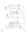
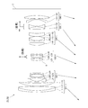
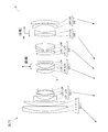
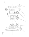
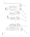
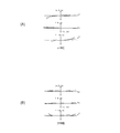
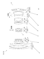
- FIG. 6 is a lens configuration diagram of the variable power optical system according to Example 1 upon focusing on infinity in the wide-angle end state.
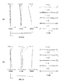
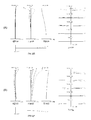
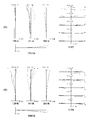
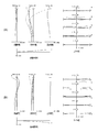
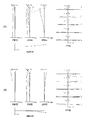
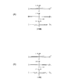
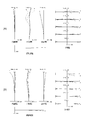
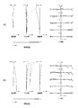
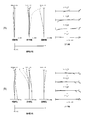
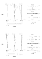
- 2A and 2B are graphs showing various aberrations of the variable power optical system according to Example 1 upon focusing on infinity in the wide-angle end state and the telephoto end state, respectively.
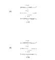
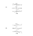
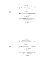
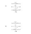
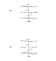
- FIG. 3A and FIG. 3B are coma aberration diagrams when blur correction is performed in the wide-angle end state and the telephoto end state of the variable power optical system according to the first example, respectively.
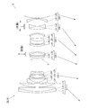
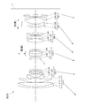
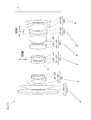
- FIG. 9 is a lens configuration diagram of the variable power optical system according to Example 2 upon focusing on infinity in the wide-angle end state.
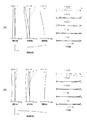
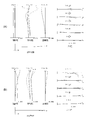
- FIG. 5B are graphs showing various aberrations of the variable power optical system according to Example 2 upon focusing on infinity in the wide-angle end state and the telephoto end state, respectively.
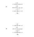
- FIG. 6A and FIG. 6B are coma aberration diagrams when blur correction is performed in the wide-angle end state and the telephoto end state of the variable power optical system according to the second example, respectively.
- FIG. 9 is a lens configuration diagram of the variable power optical system according to Example 3 upon focusing on infinity in the wide-angle end state.
- FIG. 8A and FIG. 8B are aberration diagrams of the variable power optical system according to Example 3 upon focusing on infinity in the wide-angle end state and the telephoto end state, respectively.
- FIG. 9A and 9B are coma aberration diagrams when blur correction is performed in the wide-angle end state and the telephoto end state of the variable power optical system according to the third example, respectively.
- FIG. 19 is a lens configuration diagram of the variable power optical system according to Example 4 upon focusing on infinity in the wide-angle end state.
- 11A and 11B are aberration diagrams of the variable power optical system according to Example 4 upon focusing on infinity in the wide-angle end state and the telephoto end state, respectively.
- 12A and 12B are coma aberration diagrams when blur correction is performed in the wide-angle end state and the telephoto end state of the variable power optical system according to the fourth example, respectively.
- FIG. 19 is a lens configuration diagram of the variable power optical system according to Example 4 upon focusing on infinity in the wide-angle end state.
- 11A and 11B are aberration diagrams of the variable power optical system according to Example 4 upon focusing on infinity in the wide-angle end state and the telephoto end state,
- FIG. 13 is a lens configuration diagram of the variable power optical system according to Example 5 upon focusing on infinity in the wide-angle end state.
- FIG. 14A and FIG. 14B are aberration diagrams of the variable power optical system according to Example 5 upon focusing on infinity in the wide-angle end state and the telephoto end state, respectively.
- FIGS. 15A and 15B are coma aberration diagrams when blur correction is performed in the wide-angle end state and the telephoto end state of the variable power optical system according to the fifth example, respectively.
- FIG. 16 is a lens configuration diagram of the variable power optical system according to Example 6 upon focusing on infinity in the wide-angle end state.
- 17B are aberration diagrams of the variable power optical system according to the sixth example at the wide-angle end state and the telephoto end state at the time of focusing at infinity, respectively.
- 18A and 18B are coma aberration diagrams when blur correction is performed in the wide-angle end state and the telephoto end state of the variable power optical system according to the sixth example, respectively.
- It is a lens block diagram at the time of focusing on infinity in the wide-angle end state of the variable power optical system of the seventh example.
- 20A and 20B are aberration diagrams of the variable power optical system according to the seventh example at the wide-angle end state and the telephoto end state, respectively, upon focusing on infinity.
- 21A and 21B are coma aberration diagrams when blur correction is performed in the wide-angle end state and the telephoto end state of the variable power optical system according to the seventh example, respectively.
- FIG. 19 is a lens configuration diagram of the variable power optical system according to Example 8 upon focusing on infinity in the wide-angle end state.
- 23A and 23B are graphs showing various aberrations of the variable power optical system according to Example 8 upon focusing on infinity in the wide-angle end state and the telephoto end state, respectively.
- 24A and 24B are coma aberration diagrams when blur correction is performed in the wide-angle end state and the telephoto end state of the variable power optical system according to the eighth example, respectively.
- FIGS. 26A and 26B are aberration diagrams of the variable power optical system according to the ninth example at the wide-angle end state and the telephoto end state, respectively, upon focusing on infinity.
- 27A and 27B are coma aberration diagrams when blur correction is performed in the wide-angle end state and the telephoto end state of the variable power optical system according to the ninth example, respectively.
- 29A and 29B are aberration diagrams of the variable power optical system according to the tenth example upon focusing on infinity in the wide-angle end state and the telephoto end state, respectively.
- 30A and 30B are coma aberration diagrams when blur correction is performed in the wide-angle end state and the telephoto end state of the variable power optical system according to the tenth example, respectively.
- FIG. 19 is a lens configuration diagram of the variable magnification optical system according to the eleventh example when focused on infinity in the wide-angle end state.
- 32A and 32B are aberration diagrams of the variable power optical system according to the eleventh example at the wide-angle end state and the telephoto end state, respectively, upon focusing on infinity.
- 33A and 33B are coma aberration diagrams when blur correction is performed in the wide-angle end state and the telephoto end state of the variable power optical system according to the eleventh example, respectively. It is a lens block diagram at the time of focusing on infinity in the wide-angle end state of the variable power optical system of the twelfth example.
- FIG. 35A and FIG. 35B are aberration diagrams at the time of focusing at infinity in the wide-angle end state and the telephoto end state of the variable power optical system according to the twelfth example, respectively.
- 36A and 36B are coma aberration diagrams when blur correction is performed in the wide-angle end state and the telephoto end state of the variable power optical system according to the twelfth example, respectively.
- FIG. 38A and 38B are aberration diagrams of the variable power optical system according to the thirteenth example at the wide-angle end state and the telephoto end state, respectively, upon focusing on infinity.
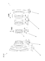
- 39A and 39B are coma aberration diagrams when blur correction is performed in the wide-angle end state and the telephoto end state of the variable power optical system according to the thirteenth example, respectively. It is a figure which shows the structure of the camera provided with the variable power optical system which concerns on this embodiment. 6 is a flowchart showing a method for manufacturing a variable power optical system according to the present embodiment.
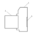
- the camera 1 is a digital camera equipped with a variable power optical system according to this embodiment as a taking lens 2.
- the taking lens 2 In the camera 1, light from an unillustrated object (subject) is condensed by the taking lens 2 and reaches the image sensor 3.
- the image sensor 3 Thus, the light from the subject is captured by the image sensor 3 and recorded as a subject image in a memory (not shown).
- this camera may be a mirrorless camera or a single-lens reflex type camera having a quick return mirror.
- variable power optical system ZL(1) as an example of the variable power optical system (zoom lens) ZL according to the present embodiment has a positive refracting power arranged in order from the object side. It has a lens group G1 and a second lens group G2 having a negative refractive power. At the time of zooming, the distance between adjacent lens groups changes. Further, the variable power optical system ZL(1) has a diaphragm (aperture diaphragm S) arranged on the image side of the second lens group G2. This makes it possible to suppress variations in astigmatism and spherical aberration during zooming.
- variable power optical system ZL satisfies the following conditional expression (1).
- Df distance from the lens surface closest to the object of the variable power optical system ZL in the wide-angle end state to the diaphragm
- Dr distance from the diaphragm at the wide-angle end state to the lens surface closest to the image of the variable magnification optical system ZL
- variable power optical system ZL may be the variable power optical system ZL(2) shown in FIG. 4, the variable power optical system ZL(3) shown in FIG. 7, or the variable power optical system shown in FIG. ZL(4) or the variable power optical system ZL(5) shown in FIG. 13 may be used.
- the variable power optical system ZL according to this embodiment may be the variable power optical system ZL(6) shown in FIG. 16, the variable power optical system ZL(7) shown in FIG. 19, or the variable power shown in FIG.
- the optical system ZL(8) may be used, or the variable power optical system ZL(9) shown in FIG. 25 may be used.
- variable power optical system ZL may be the variable power optical system ZL(10) shown in FIG. 28, the variable power optical system ZL(11) shown in FIG. 31, or the variable power shown in FIG.
- the optical system ZL(12) may be used, or the variable power optical system ZL(13) shown in FIG. 37 may be used.
- Conditional expression (1) defines the position of the diaphragm in the wide-angle end state. By satisfying the conditional expression (1), it is possible to suppress variations in spherical aberration and field curvature during zooming.
- conditional expression (1) If the corresponding value of conditional expression (1) is less than the lower limit value, it becomes difficult to suppress the fluctuation of the field curvature during zooming.
- the lower limit values of conditional expression (1) are set to 0.30, 0.40, 0.50, 0.53, 0.55, 0.58, 0. .60, 0.61, 0.62, 0.63, and even 0.64.
- conditional expression (1) If the corresponding value of conditional expression (1) exceeds the upper limit value, it becomes difficult to suppress the fluctuation of the field curvature during zooming. By setting the upper limit of conditional expression (1) to 0.89, the effect of this embodiment can be made more reliable. In order to further secure the effect of this embodiment, the upper limit values of conditional expression (1) are set to 0.88, 0.87, 0.86, 0.85, 0.83, 0.80, 0. It may be set to 0.78, or 0.75.
- the variable power optical system ZL has a first lens group G1 having a positive refracting power, a second lens group G2 having a negative refracting power, and a positive refracting power which are arranged in order from the object side.
- the third lens group G3 has, the fourth lens group G4 having a positive refractive power, the fifth lens group G5, and the sixth lens group G6, and the diaphragm has the second lens group G2 and the fourth lens group. It is desirable to be arranged between the G4 and the G4. This makes it possible to suppress variations in astigmatism and spherical aberration during zooming.
- variable power optical system ZL satisfies the following conditional expression (2).
- TLw total length of the variable power optical system ZL in the wide-angle end state
- fw focal length of the variable power optical system ZL in the wide-angle end state
- Conditional expression (2) defines the ratio between the total length of the variable power optical system ZL and the focal length of the variable power optical system ZL in the wide-angle end state.
- conditional expression (2) If the corresponding value of conditional expression (2) is less than the lower limit value, it becomes difficult to correct the field curvature.
- the lower limit values of the conditional expression (2) are set to 2.00, 2.50, 3.00, 3.50, 4.00, 4.30, 4 It may be set to .50, 4.60, or 4.70.
- conditional expression (2) If the corresponding value of conditional expression (2) exceeds the upper limit value, it becomes difficult to correct the field curvature.
- the upper limit of conditional expression (2) is set to 7.00, 6.80, 6.50, 6.30, 6.00, 5.80, 5 .50, 5.40, 5.30, or even 5.25.
- the variable power optical system ZL has a first lens group G1 having a positive refracting power, a second lens group G2 having a negative refracting power, and a positive refracting power which are arranged in order from the object side. It has the third lens group G3 which has, the fourth lens group G4 having a positive refractive power, the fifth lens group G5, and the sixth lens group G6, and may satisfy the following conditional expression (3). desirable.
- Mv3 the amount of movement of the third lens group G3 during zooming from the wide-angle end state to the telephoto end state (the sign of the amount of movement to the object side is +)
- Mv4 Amount of movement of the fourth lens group G4 during zooming from the wide-angle end state to the telephoto end state (+ is the sign of the amount of movement toward the object side)
- Conditional expression (3) defines the ratio of the movement amount of the third lens group G3 and the movement amount of the fourth lens group G4 when the magnification is changed from the wide-angle end state to the telephoto end state.
- conditional expression (3) If the corresponding value of conditional expression (3) is less than the lower limit value, it becomes difficult to suppress the fluctuation of the field curvature during zooming.
- the lower limit values of the conditional expression (3) are set to 1.10, 1.15, 1.18, 1.20, 1.23, 1.25, 1 It may be set to 0.28, 1.30, 1.33, or 1.35.
- conditional expression (3) exceeds the upper limit, it becomes difficult to correct the field curvature in the wide-angle end state.
- the upper limit values of the conditional expression (3) are set to 2.50, 2.30, 2.00, 1.80, 1.65, 1.62, 1 .60, 1.58, 1.55, 1.53, and even 1.50.
- variable power optical system ZL preferably satisfies the following conditional expression (4).
- Mv2 the amount of movement of the second lens group G2 at the time of zooming from the wide-angle end state to the telephoto end state (the sign of the amount of movement to the object side is +)
- fw focal length of the variable magnification optical system ZL in the wide-angle end state
- Conditional expression (4) defines the amount of movement of the second lens group G2 during zooming from the wide-angle end state to the telephoto end state.
- the conditional expression (4) means that the second lens group G2 moves toward the object side during zooming from the wide-angle end state to the telephoto end state.
- conditional expression (4) If the corresponding value of conditional expression (4) is below the lower limit value, it becomes difficult to correct spherical aberration in the telephoto end state.
- the lower limit values of conditional expression (4) are set to 0.08, 0.10, 0.13, 0.15, 0.18, 0.20, 0. .22, and may be set to 0.24.
- conditional expression (4) If the corresponding value of conditional expression (4) exceeds the upper limit value, it becomes difficult to correct spherical aberration in the telephoto end state.
- the upper limit values of conditional expression (4) are set to 5.00, 3.00, 2.50, 2.20, 2.00, 1.80, 1, .50, 1.30, 1.10, 0.95, 0.90, 0.85, 0.80, 0.75, and even 0.70.
- the variable power optical system ZL has a first lens group G1 having a positive refracting power, a second lens group G2 having a negative refracting power, and a positive refracting power which are arranged in order from the object side.
- the third lens group G3 has, the fourth lens group G4 having a positive refractive power, the fifth lens group G5, and the sixth lens group G6, and in the variable power optical system ZL at the time of zooming.
- Multiple lens groups move, the distance between adjacent lens groups changes, and the lens group closest to the image and the diaphragm that move during zooming move integrally during zooming It is desirable to do. As a result, the lens barrel including the mechanical mechanism can be downsized while ensuring good optical performance.
- the variable power optical system ZL has a first lens group G1 having a positive refracting power, a second lens group G2 having a negative refracting power, and a positive refracting power which are arranged in order from the object side.
- the third lens group G3 has, the fourth lens group G4 having a positive refractive power, the fifth lens group G5, and the sixth lens group G6, and in the variable power optical system ZL at the time of zooming.
- a plurality of lens groups including the third lens group G3 move, the distance between adjacent lens groups changes, and the lens group closest to the image side and the third lens group G3 among the lens groups that move during zooming.
- the lens barrel including the mechanical mechanism can be downsized while ensuring good optical performance.
- the variable power optical system ZL has a first lens group G1 having a positive refracting power, a second lens group G2 having a negative refracting power, and a positive refracting power which are arranged in order from the object side. It has the 3rd lens group G3 which has, the 4th lens group G4 which has positive refractive power, the 5th lens group G5, and the 6th lens group G6, and the 6th lens group G6 has two or more lenses. It is desirable to consist of This makes it possible to suppress field curvature and lateral chromatic aberration.
- the variable power optical system ZL has a first lens group G1 having a positive refracting power, a second lens group G2 having a negative refracting power, and a positive refracting power which are arranged in order from the object side.
- the third lens group G3 has, the fourth lens group G4 having a positive refractive power, the fifth lens group G5, and the sixth lens group G6, and the sixth lens group G6 and the diaphragm have variable magnification. It is desirable to move integrally during this. As a result, the lens barrel including the mechanical mechanism can be downsized while ensuring good optical performance.
- the variable power optical system ZL has a first lens group G1 having a positive refracting power, a second lens group G2 having a negative refracting power, and a positive refracting power which are arranged in order from the object side. It has the 3rd lens group G3 which has, the 4th lens group G4 which has positive refracting power, the 5th lens group G5, and the 6th lens group G6, and the 6th lens group G6 and the 3rd lens group G3.
- the variable power optical system ZL has a first lens group G1 having a positive refracting power, a second lens group G2 having a negative refracting power, and a positive refracting power which are arranged in order from the object side.
- the third lens group G3 has, the fourth lens group G4 having a positive refractive power, the fifth lens group G5, and the sixth lens group G6, and the diaphragm and the third lens group G3 have a variable power. It is desirable to move integrally during this. As a result, the lens barrel including the mechanical mechanism can be downsized while ensuring good optical performance.
- the variable power optical system ZL has a first lens group G1 having a positive refracting power, a second lens group G2 having a negative refracting power, and a positive refracting power which are arranged in order from the object side. It has the 3rd lens group G3 which has, the 4th lens group G4 which has positive refracting power, the 5th lens group G5, and the 6th lens group G6, and the 3rd lens group G3 is perpendicular to an optical axis. It is desirable to include a vibration isolation group having a positive refractive power that is movable so as to have a directional displacement component. Accordingly, it is possible to suppress the fluctuation of the field curvature before and after the shake correction.
- variable power optical system ZL satisfies the following conditional expression (5).
- f3b focal length of the image stabilization group
- f3 focal length of the third lens group G3
- Conditional expression (5) defines the ratio between the focal length of the image stabilizing unit and the focal length of the third lens unit G3.
- conditional expression (5) If the corresponding value of conditional expression (5) is less than the lower limit value, it becomes difficult to suppress the fluctuation of spherical aberration before and after blurring correction.
- the lower limit values of conditional expression (5) are set to 0.70, 0.80, 0.85, 0.90, 0.95, 0.99, and 1. .10, 1, 20 and may be set to 1.30.
- conditional expression (5) exceeds the upper limit value, it will be difficult to obtain the image stabilization effect.
- the upper limit values of conditional expression (5) are set to 3.50, 3.40, 3.00, 2.80, 2.40, 2.10, 1 It may be set to 0.80, or 1.60.
- variable power optical system ZL satisfies the following conditional expression (6).
- ⁇ T3r Magnification of lens group consisting of lenses arranged on the image side of the image stabilizing group in the telephoto end state
- ⁇ T3b Magnification of image stabilizing group in the telephoto end state
- Conditional expression (6) defines the relationship between the magnification of the lens group consisting of the lens arranged on the image side of the image stabilizing group and the magnification of the image stabilizing group in the telephoto end state.
- conditional expression (6) If the corresponding value of conditional expression (6) is less than the lower limit value, it becomes difficult to suppress the variation of spherical aberration before and after blurring correction.
- the lower limit values of conditional expression (6) are set to 0.70, 0.80, 0.90, 0.95, 0.98, 1.05, 1 .10, 1.20 and even 1.30.
- conditional expression (6) If the corresponding value of conditional expression (6) exceeds the upper limit value, it becomes difficult to suppress the variation of spherical aberration before and after the shake correction.
- the upper limit values of conditional expression (6) are set to 3.00, 2.50, 2.10, 1.90, 1.80, 1.70, and It may be set to 1.60.
- the image stabilizing group has a positive lens and a negative lens.
- the image stabilizing group has a positive lens and a negative lens.
- the third lens group G3 includes a 3a group, a 3b group, and a 3c group, which are arranged in order from the object side, and the 3b group is a vibration reduction group. Is desirable. This makes it possible to suppress fluctuations in spherical aberration before and after blurring correction.
- variable power optical system ZL satisfies the following conditional expression (7).
- f3c focal length of 3c group
- f3b focal length of image stabilization group
- Conditional expression (7) defines the ratio between the focal length of the 3cth group and the focal length of the image stabilization group.
- the spherical aberration generated in the image stabilizing group (group 3b) at the time of blur correction in the group 3c becomes excessive.
- the lower limit values of conditional expression (7) are set to 0.30, 0.35, 0.40, 0.45, 0.50, 0.55, 0. .60, and may be set to 0.62.
- the spherical aberration generated in the image stabilizing group (group 3b) at the time of blur correction in the group 3c will be insufficiently corrected.
- the upper limit values of the conditional expression (7) are set to 1.30, 1.25, 1.21, 1.10, 1.00, 0.95, 0. It may be set to 0.90, 0.85, 0.80, or 0.75.
- the third group c should be composed of a single lens. With this, it is possible to correct the spherical aberration generated in the image stabilizing group (the 3b group) at the time of blur correction with the minimum lens configuration.
- the third group c should be composed of a negative single lens. Accordingly, with the minimum lens configuration, it is possible to excellently correct the spherical aberration generated in the image stabilizing group (the third group b) at the time of blur correction.
- the third group c is composed of a negative single lens and satisfies the following conditional expression (8).
- R3c1 radius of curvature of the object-side lens surface of the negative single lens of the 3c-th group
- R3c2 radius of curvature of the image-side lens surface of the negative single-lens of the 3cth group
- Conditional expression (8) defines the shape factor of the negative single lens forming the 3c-th group.
- conditional expression (8) If the corresponding value of conditional expression (8) is less than the lower limit value, it becomes difficult to suppress variations in spherical aberration and field curvature before and after blurring correction.
- the lower limit of conditional expression (8) is set to ⁇ 0.60, ⁇ 0.10, 0.10, 0.90, and further 1.10. May be.
- conditional expression (8) If the corresponding value of conditional expression (8) exceeds the upper limit value, it becomes difficult to suppress variations in spherical aberration and field curvature before and after blurring correction.
- the upper limit of conditional expression (8) is set to 5.00, 4.50, 4.00, 3.50, 3.00, 2.50, 2. .20, and may be set to 2.00.
- variable power optical system ZL satisfies the following conditional expression (9).
- ft focal length of the variable power optical system ZL in the telephoto end state
- fw focal length of the variable power optical system ZL in the wide angle end state
- Conditional expression (9) defines the variable power ratio of the variable power optical system ZL. By satisfying conditional expression (9), it is possible to maximize the effects of the present embodiment at a high zoom ratio. By setting the lower limit of conditional expression (9) to 3.30, the effect of this embodiment can be made more reliable. In order to further secure the effect of the present embodiment, the lower limit of conditional expression (9) is set to 3.50, 4.00, 4.50, 5.00, 6.00, and further 7.00. You may set it. Further, by setting the upper limit of conditional expression (9) to 25.00, the effect of the present embodiment can be made more reliable. In order to further secure the effect of the present embodiment, even if the upper limit value of the conditional expression (9) is set to 20.00, 15.00, 10.00, 9.00, and further 8.00. Good.
- variable power optical system ZL satisfies the following conditional expression (10).
- Conditional expression (10) defines the half angle of view of the variable power optical system ZL in the wide-angle end state. By satisfying the conditional expression (10), it is possible to satisfactorily correct the field curvature. By setting the lower limit of conditional expression (10) to 38.0°, the effect of the present embodiment can be made more reliable. In order to further secure the effect of this embodiment, the lower limit of conditional expression (10) may be set to 40.0°. Further, by setting the upper limit of conditional expression (10) to 70.0°, the effect of this embodiment can be made more reliable. In order to further secure the effect of this embodiment, the upper limit of conditional expression (10) may be set to 60.0°, 50.0°, and further 45.0°.
- variable power optical system ZL satisfies the following conditional expression (11).
- ⁇ t is the half angle of view of the variable magnification optical system ZL in the telephoto end state.
- Conditional expression (11) defines the half angle of view of the variable power optical system ZL in the telephoto end state. By satisfying conditional expression (11), it is possible to maximize the effect of the present embodiment at a high zoom ratio. By setting the lower limit of conditional expression (11) to 4.0°, the effect of the present embodiment can be made more reliable. In order to further secure the effect of this embodiment, the lower limit value of the conditional expression (11) may be set to 5.0°, and further to 5.5°. Moreover, by setting the upper limit value of the conditional expression (11) to 13.0°, the effect of the present embodiment can be made more reliable. In order to further secure the effect of the present embodiment, even if the upper limit value of the conditional expression (11) is set to 12.0°, 11.0°, 10.0°, and further 9.0°. Good.
- the variable power optical system ZL has a first lens group G1 having a positive refracting power, a second lens group G2 having a negative refracting power, and a positive refracting power which are arranged in order from the object side. It is desirable that the third lens group G3 that has the third lens group G3 and the following conditional expression (12) be satisfied.
- fw focal length of the variable-magnification optical system ZL in the wide-angle end state
- f123w composite focal length of the first lens group G1, the second lens group G2, and the third lens group G3 in the wide-angle end state
- Conditional expression (12) defines the ratio of the focal length of the variable power optical system ZL to the combined focal length of the first lens group G1, the second lens group G2, and the third lens group G3 in the wide-angle end state. It is a thing.
- the conditional expression (12) means that the first lens group G1, the second lens group G2, and the third lens group G3 are substantially afocal in the wide-angle end state. By satisfying the conditional expression (12), it is possible to excellently correct spherical aberration and field curvature in the wide-angle end state.
- conditional expression (12) If the corresponding value of conditional expression (12) is below the lower limit, it becomes difficult to correct spherical aberration in the wide-angle end state.
- the lower limit values of conditional expression (12) may be set to ⁇ 0.25, ⁇ 0.20, ⁇ 0.15, and further ⁇ 0.12. Good.
- conditional expression (12) If the corresponding value of conditional expression (12) exceeds the upper limit value, it becomes difficult to correct spherical aberration in the wide-angle end state.
- the upper limit of conditional expression (12) By setting the upper limit of conditional expression (12) to 0.55, the effect of this embodiment can be made more reliable.
- the upper limits of conditional expression (12) are set to 0.50, 0.45, 0.40, 0.35, 0.30, 0.25, 0. .20, 0.15, 0.10, or even 0.05.
- the variable power optical system ZL has a first lens group G1 having a positive refracting power, a second lens group G2 having a negative refracting power, and a positive refracting power which are arranged in order from the object side. It is desirable that the second lens group G3 has the third lens group G3 and the following conditional expression (13) is satisfied.
- ft focal length of the variable magnification optical system ZL in the telephoto end state
- f123t composite focal length of the first lens group G1, the second lens group G2 and the third lens group G3 in the telephoto end state
- Conditional expression (13) defines the ratio of the focal length of the variable power optical system ZL to the combined focal length of the first lens group G1, the second lens group G2, and the third lens group G3 in the telephoto end state. It is a thing.
- Conditional expression (13) means that the first lens group G1, the second lens group G2, and the third lens group G3 are substantially afocal in the telephoto end state.
- conditional expression (13) If the corresponding value of conditional expression (13) is below the lower limit, it becomes difficult to correct spherical aberration in the telephoto end state.
- the lower limit value of the conditional expression (13) may be set to ⁇ 1.00, ⁇ 0.90, and ⁇ 0.80.
- conditional expression (13) If the corresponding value of conditional expression (13) exceeds the upper limit value, it becomes difficult to correct spherical aberration in the telephoto end state.
- the upper limit of conditional expression (13) may be set to 0.20, 0.10, ⁇ 0.10, and further ⁇ 0.20.
- variable power optical system ZL satisfies the following conditional expression (14).
- BFw Distance from the lens surface closest to the image side of the variable power optical system ZL in the wide-angle end state to the image surface
- fw Focal length of the variable power optical system ZL in the wide-angle end state
- Conditional expression (14) defines the ratio between the back focus of the variable power optical system ZL and the focal length of the variable power optical system ZL in the wide-angle end state.
- conditional expression (14) If the corresponding value of conditional expression (14) is below the lower limit, it becomes difficult to correct the field curvature in the wide-angle end state.
- the lower limit value of the conditional expression (14) may be set to 0.30, 0.35, 0.37, and 0.40.
- conditional expression (14) If the corresponding value of conditional expression (14) exceeds the upper limit value, correction of the field curvature in the wide-angle end state will be insufficient.
- the upper limit of conditional expression (14) may be set to 0.54, 0.52, and 0.50.
- the variable power optical system ZL has a first lens group G1 having a positive refracting power, a second lens group G2 having a negative refracting power, and a positive refracting power which are arranged in order from the object side. It has a third lens group G3 that it has, a fourth lens group G4 that has a positive refractive power, and a fifth lens group G5, and the fifth lens group G5 moves with respect to the image plane during focusing. Is desirable. As a result, it is possible to suppress variation in spherical aberration during focusing.
- the variable power optical system ZL has a first lens group G1 having a positive refracting power, a second lens group G2 having a negative refracting power, and a positive refracting power which are arranged in order from the object side.
- the third lens group G3 has, the fourth lens group G4 having a positive refractive power, and the fifth lens group G5.
- the fifth lens group G5 includes at least one positive lens and at least one positive lens. It is desirable to have a negative lens. This makes it possible to suppress the fluctuation of the field curvature during focusing.
- the variable power optical system ZL has a first lens group G1 having a positive refracting power, a second lens group G2 having a negative refracting power, and a positive refracting power which are arranged in order from the object side. It is desirable to have the third lens group G3 that has, the fourth lens group G4 having a positive refractive power, and the fifth lens group G5, and to satisfy the following conditional expression (15).
- f5 focal length of the fifth lens group G5
- fw focal length of the variable magnification optical system ZL in the wide-angle end state
- conditional expression (15) defines the ratio between the focal length of the fifth lens group G5 and the focal length of the variable magnification optical system ZL in the wide-angle end state.
- the lower limit value of the conditional expression (15) may be set to 1.20, 1.30, 1.40, and further 1.45.
- conditional expression (15) exceeds the upper limit value, the correction of the curvature of field that occurs during focusing becomes insufficient. Further, the amount of movement of the fifth lens group G5 at the time of focusing becomes large, so that the lens barrel becomes large.
- the upper limit values of the conditional expression (15) are set to 10.00, 8.00, 5.00, 4.00, 3.00, 2.45, and 2. .38, 2.33, 2.28, 2.25, or 2.10.
- the variable power optical system ZL has a first lens group G1 having a positive refracting power, a second lens group G2 having a negative refracting power, and a positive refracting power which are arranged in order from the object side.
- a third lens group G3 that has, a fourth lens group G4 having a positive refractive power, a fifth lens group G5, and a sixth lens group G6, and may satisfy the following conditional expression (16). desirable.
- Mv5 the amount of movement of the fifth lens group G5 at the time of zooming from the wide-angle end state to the telephoto end state (the sign of the amount of movement to the object side is +)
- Mv6 Amount of movement of the sixth lens group G6 during zooming from the wide-angle end state to the telephoto end state (the sign of the amount of movement toward the object side is +)
- conditional expression (16) defines the ratio of the movement amount of the fifth lens group G5 and the movement amount of the sixth lens group G6 when the magnification is changed from the wide-angle end state to the telephoto end state.
- the lower limit value of the conditional expression (16) may be set to 1.20, 1.30, and further 1.40.
- the upper limit value of the conditional expression (16) may be set to 2.00, 1.80, and further 1.60.
- variable power optical system ZL it is desirable that the first lens group G1 moves with respect to the image plane during zooming. This makes it possible to obtain a high zoom ratio.
- variable power optical system ZL it is desirable that the first lens group G1 be composed of three or more lenses. Thereby, spherical aberration can be satisfactorily corrected especially in the telephoto end state. Further, it becomes possible to obtain a high zoom ratio.
- variable power optical system ZL satisfies the following conditional expression (17).
- Mv1 the amount of movement of the first lens group G1 during zooming from the wide-angle end state to the telephoto end state (the sign of the amount of movement to the object side is +)
- ft focal length of variable power optical system ZL in telephoto end state
- fw focal length of variable power optical system ZL in wide angle end state
- conditional expression (17) defines the moving amount of the first lens group G1 with respect to the change of the focal length at the time of zooming from the wide-angle end state to the telephoto end state.
- conditional expression (17) If the corresponding value of conditional expression (17) is below the lower limit, it becomes difficult to correct spherical aberration in the telephoto end state.
- the lower limit values of the conditional expression (17) may be set to 0.33, 0.34, and 0.35.
- conditional expression (17) exceeds the upper limit, it becomes difficult to correct the field curvature in the telephoto end state.
- the diameter of the first lens group G1 increases, and the weight of the lens barrel increases.
- the upper limit of conditional expression (17) is set to 0.70, 0.65, 0.58, 0.50, 0.45, and 0.40. You may set it.
- the variable power optical system ZL has a first lens group G1 having a positive refracting power, a second lens group G2 having a negative refracting power, and a positive refracting power which are arranged in order from the object side.
- the third lens group G3 has, the fourth lens group G4 having a positive refractive power, the fifth lens group G5, and the sixth lens group G6, and the sixth lens group G6 is provided with an air lens, It is desirable to satisfy the following conditional expression (18).
- RAr1 radius of curvature of the object-side lens surface of the air lens of the sixth lens group G6
- RAr2 radius of curvature of the image-side lens surface of the air lens of the sixth lens group G6
- the conditional expression (18) defines the shape factor of the air lens provided in the sixth lens group G6. By satisfying the conditional expression (18), it is possible to excellently correct the field curvature.
- conditional expression (18) If the corresponding value of conditional expression (18) is below the lower limit, it becomes difficult to correct the field curvature.
- the lower limit of conditional expression (18) is set to 0.10, 0.20, 0.28, 0.30, 0.40, and 0.45. You may set it.
- conditional expression (18) exceeds the upper limit value, it becomes difficult to correct the field curvature.
- the upper limit value of the conditional expression (18) may be set to 1.70, 1.50, 1.20, and further 1.00.
- the variable power optical system ZL has a first lens group G1 having a positive refracting power, a second lens group G2 having a negative refracting power, and a positive refracting power which are arranged in order from the object side. It has a third lens group G3 that has, a fourth lens group G4 having a positive refractive power, a fifth lens group G5, and a sixth lens group G6, and at least the first lens group during zooming. It is desirable that G1, the third lens group G3, the fourth lens group G4, the fifth lens group G5, and the sixth lens group G6 move with respect to the image plane. This makes it possible to increase the variation in the magnification of each lens unit during zooming. Further, it becomes possible for the fourth lens group G4 to correct the aberration that occurs in the third lens group G3 during zooming.
- variable power optical system ZL it is desirable that the lens group that moves during zooming moves toward the object side during zooming from the wide-angle end state to the telephoto end state. As a result, it is possible to secure a sufficient zoom ratio that satisfies the performance of this embodiment.
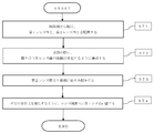
- a manufacturing method of the variable power optical system ZL according to the present embodiment will be outlined with reference to FIG.
- a first lens group G1 having a positive refractive power and a second lens group G2 having a negative refractive power are arranged in order from the object side (step ST1).
- the configuration is such that the distance between adjacent lens groups changes during zooming (step ST2).
- a diaphragm is arranged on the image side of the second lens group G2 (step ST3).
- each lens is arranged in the lens barrel so as to satisfy at least the conditional expression (1) (step ST4). According to such a manufacturing method, it becomes possible to manufacture a variable power optical system having a high variable power ratio and good optical performance.
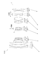
- a variable power optical system ZL according to an example of this embodiment will be described below with reference to the drawings. 1, FIG. 4, FIG. 7, FIG. 10, FIG. 13, FIG. 16, FIG. 19, FIG. 22, FIG. 25, FIG. 28, FIG. 31, FIG. 34, and FIG. It is a sectional view showing composition and refractive power distribution of magnification optical system ZL ⁇ ZL (1)-ZL (13) ⁇ .
- the moving direction along the optical axis of the lens group that moves during zooming from the wide-angle end state to the telephoto end state is indicated by an arrow.
- the moving direction when the focusing group focuses on an object at a short distance from infinity is indicated by an arrow together with the character "focus”.
- At least a part of the third lens group G3 serves as an image stabilization group, and the moving direction when correcting image blur is indicated by an arrow together with the word "image stabilization”.
- FIG. 1 In these figures (FIG. 1, FIG. 4, FIG. 7, FIG. 10, FIG. 13, FIG. 16, FIG. 19, FIG. 22, FIG. 25, FIG. 28, FIG. 31, FIG. 34, FIG.
- Each lens is represented by a combination of symbol L and a numeral by a combination of G and a numeral.
- the lens groups and the like are represented independently by using combinations of symbols and numbers for each embodiment. Therefore, even if the same combination of reference numerals and numbers is used between the embodiments, it does not mean that they have the same configuration.
- Tables 1 to 13 are shown below, in which Table 1 is the first embodiment, Table 2 is the second embodiment, Table 3 is the third embodiment, Table 4 is the fourth embodiment, and Table 5 is the first embodiment.
- Table 6 is 6th Example
- Table 7 is 7th Example
- Table 8 is 8th Example
- Table 9 is 9th Example
- Table 10 is 10th Example
- Table 11 is 11th Example.
- Table 12 is a table showing each specification data in the twelfth embodiment
- Table 13 is a table showing each specification data in the thirteenth embodiment.
- FNO is the F number
- ⁇ is the half angle of view (unit is ° (degrees))
- Y is the image height.
- TL indicates the distance from the lens front surface to the final lens surface on the optical axis when focused on infinity, plus BF.
- BF is the image from the final lens surface on the optical axis when focused on infinity.
- the air equivalent distance (back focus) to the surface I is shown. Note that these values are shown for each of the wide-angle end (W), the first intermediate focal length (M1), the second intermediate focal length (M2), and the telephoto end (T) in each variable power state.
- f3b represents the focal length of the image stabilizing group.
- f3c indicates the focal length of the 3c-th group.
- ⁇ T3r represents the magnification of a lens unit including lenses arranged on the image side of the image stabilizing unit in the telephoto end state.
- ⁇ T3b represents the magnification of the image stabilization group in the telephoto end state.
- f123w represents a combined focal length of the first lens group G1, the second lens group G2, and the third lens group G3 in the wide-angle end state.
- f123t represents a combined focal length of the first lens group G1, the second lens group G2, and the third lens group G3 in the telephoto end state.
- the surface number indicates the order of the optical surface from the object side along the traveling direction of the light ray, and R represents the radius of curvature of each optical surface (the surface whose center of curvature is located on the image side). Is a positive value), D is a surface distance that is the distance on the optical axis from each optical surface to the next optical surface (or image surface), nd is the refractive index of the material of the optical member with respect to the d-line, and ⁇ d is the optical The Abbe numbers based on the d-line of the material of the member are shown.
- the radius of curvature “ ⁇ ” indicates a plane or an aperture, and (stop S) indicates an aperture stop.
- the surface number is marked with * and the radius of curvature R column indicates the paraxial radius of curvature.
- X(y) is the distance (zag amount) along the optical axis from the tangent plane at the apex of the aspherical surface to the position on the aspherical surface at the height y
- R is the radius of curvature of the reference spherical surface (paraxial radius of curvature).
- ⁇ is a conic constant
- Ai is an i-th order aspherical coefficient.
- the quadratic aspherical coefficient A2 is 0, and the description thereof is omitted.
- the [Lens group data] table shows the starting surface (the surface closest to the object) and the focal length of each lens group.
- the table of [Variable spacing data] shows the surface spacing at the surface number where the surface spacing is “variable” in the table showing [lens specifications].
- W wide-angle end
- M1 first intermediate focal length
- M2 second intermediate focal length
- T telephoto end
- the [Values corresponding to conditional expressions] table shows the values corresponding to each conditional expression.
- the focal length f, radius of curvature R, surface distance D, and other lengths listed are generally “mm” unless otherwise specified, but the optical system is enlarged proportionally. Alternatively, the same optical performance can be obtained even if the proportion is reduced, and the present invention is not limited to this.
- FIG. 1 is a lens configuration diagram of the variable power optical system according to Example 1 upon focusing on infinity in the wide-angle end state.
- the variable power optical system ZL(1) according to the first example includes a first lens group G1 having a positive refractive power, a second lens group G2 having a negative refractive power, and an aperture arranged in order from the object side.
- 6 lens group G6 is a lens group G6.
- the first lens group G1, the second lens group G2, the aperture stop S, the third lens group G3, the fourth lens group G4, the fifth lens group G5, and the The 6-lens group G6 moves along the optical axis in the direction shown by the arrow in FIG. 1, and the interval between adjacent lens groups changes.
- the aperture stop S, the third lens group G3, and the sixth lens group G6 move integrally.
- the symbol (+) or ( ⁇ ) attached to each lens group symbol indicates the refracting power of each lens group, and this is the same in all the following examples.
- the first lens group G1 includes, in order from the object side, a negative meniscus lens L11 having a convex surface directed toward the object side, a biconvex positive lens L12, and a positive meniscus lens L13 having a convex surface directed toward the object side. To be done.
- the second lens group G2 includes, in order from the object side, a negative meniscus lens L21 having a convex surface directed toward the object side, a biconcave negative lens L22, a biconvex positive lens L23, and a biconcave negative lens. It is composed of a lens L24.
- the third lens group G3 includes, in order from the object side, a biconvex positive lens L31, a cemented lens of a negative meniscus lens L32 having a convex surface facing the object side and a biconvex positive lens L33, and an object side. And a negative meniscus lens L34 having a concave surface facing toward.
- the fourth lens group G4 includes, in order from the object side, a cemented lens of a biconvex positive lens L41 and a negative meniscus lens L42 having a concave surface facing the object side, and a negative meniscus lens L43 having a convex surface facing the object side. And a cemented lens of a biconvex positive lens L44.
- the positive lens L44 has an aspherical lens surface on the image plane I side.
- the fifth lens group G5 is composed of a cemented lens made up of a biconvex positive lens L51 and a biconcave negative lens L52.
- the negative lens L52 has an aspherical lens surface on the image plane I side.
- the sixth lens group G6 is composed of a negative meniscus lens L61 having a concave surface facing the object side and a biconvex positive lens L62 arranged in order from the object side. An air lens is formed between the negative meniscus lens L61 and the positive lens L62.
- the negative meniscus lens L61 has an aspherical lens surface on the image plane I side.
- the image plane I is disposed on the image side of the sixth lens group G6.
- the cemented lens of the negative meniscus lens L32 and the positive lens L33 in the third lens group G3 constitutes an image stabilization group having a positive refractive power that is movable in the direction perpendicular to the optical axis, The displacement of the image forming position (image blur on the image plane I) due to camera shake or the like is corrected.
- the positive lens L31 in the third lens group G3 corresponds to the 3a group.
- the cemented lens of the negative meniscus lens L32 and the positive lens L33 in the third lens group G3 corresponds to the 3bth group.
- the negative meniscus lens L34 in the third lens group G3 corresponds to the 3c group.
- Table 1 below lists values of specifications of the variable power optical system according to the first example.
- FIG. 2A and FIG. 2B are aberration diagrams of the variable power optical system according to Example 1 upon focusing on infinity in the wide-angle end state and the telephoto end state, respectively.
- FIG. 3A and FIG. 3B are coma aberration diagrams when blur correction is performed in the wide-angle end state and the telephoto end state of the variable power optical system according to the first example, respectively.
- FNO represents the F number
- Y represents the image height.
- the spherical aberration diagram shows the value of the F number corresponding to the maximum aperture
- the astigmatism diagram and the distortion diagram show the maximum image height value
- the coma diagram shows the image height value.
- the solid line shows the sagittal image plane
- the broken line shows the meridional image plane.
- variable power optical system according to Example 1 has excellent aberration performance with excellent correction of various aberrations.
- FIG. 4 is a lens configuration diagram of the variable power optical system according to Example 2 upon focusing on infinity in the wide-angle end state.
- the variable power optical system ZL(2) according to the second example includes a first lens group G1 having a positive refractive power, a second lens group G2 having a negative refractive power, and an aperture arranged in order from the object side.
- a third lens group G3 having a positive refracting power provided with a diaphragm S, a fourth lens group G4 having a positive refracting power, a fifth lens group G5 having a negative refracting power, and a negative refracting power are provided.
- the sixth lens group G6 Upon zooming from the wide-angle end state to the telephoto end state, the first lens group G1, the second lens group G2, the third lens group G3 provided with the aperture stop S, the fourth lens group G4, and the fifth lens group G5. , And the sixth lens group G6 move in the direction indicated by the arrow in FIG. 4 along the optical axis, and the interval between the adjacent lens groups changes. During zooming, the aperture stop S, the third lens group G3, and the sixth lens group G6 move integrally.
- the first lens group G1 includes, in order from the object side, a negative meniscus lens L11 having a convex surface directed toward the object side, a biconvex positive lens L12, and a positive meniscus lens L13 having a convex surface directed toward the object side. To be done.
- the second lens group G2 includes, in order from the object side, a negative meniscus lens L21 having a convex surface facing the object side, a biconcave negative lens L22, a biconvex positive lens L23, and a concave surface facing the object side. And a negative meniscus lens L24 facing the lens.
- the third lens group G3 cements a biconvex positive lens L31, an aperture stop S, a negative meniscus lens L32 having a convex surface facing the object side, and a biconvex positive lens L33, which are arranged in order from the object side. It is composed of a lens and a negative meniscus lens L34 having a concave surface facing the object side.
- the fourth lens group G4 includes, in order from the object side, a cemented lens of a biconvex positive lens L41 and a negative meniscus lens L42 having a concave surface facing the object side, and a negative meniscus lens L43 having a convex surface facing the object side. And a cemented lens of a biconvex positive lens L44.
- the positive lens L44 has an aspherical lens surface on the image plane I side.
- the fifth lens group G5 is composed of a cemented lens made up of a biconvex positive lens L51 and a biconcave negative lens L52.
- the negative lens L52 has an aspherical lens surface on the image plane I side.
- the sixth lens group G6 is composed of a negative meniscus lens L61 having a concave surface facing the object side and a biconvex positive lens L62 arranged in order from the object side. An air lens is formed between the negative meniscus lens L61 and the positive lens L62.
- the negative meniscus lens L61 has an aspherical lens surface on the image plane I side.
- the image plane I is disposed on the image side of the sixth lens group G6.
- the cemented lens of the negative meniscus lens L32 and the positive lens L33 in the third lens group G3 constitutes an image stabilization group having a positive refractive power that is movable in the direction perpendicular to the optical axis, The displacement of the image forming position (image blur on the image plane I) due to camera shake or the like is corrected.
- the positive lens L31 in the third lens group G3 corresponds to the 3a group.
- the cemented lens of the negative meniscus lens L32 and the positive lens L33 in the third lens group G3 corresponds to the 3bth group.
- the negative meniscus lens L34 in the third lens group G3 corresponds to the 3c group.
- Table 2 below lists values of specifications of the variable power optical system according to the second example.
- FIG. 5A and FIG. 5B are aberration diagrams at the time of focusing at infinity in the wide-angle end state and the telephoto end state of the variable power optical system according to the second example, respectively.
- FIG. 6A and FIG. 6B are coma aberration diagrams when blur correction is performed in the wide-angle end state and the telephoto end state of the variable power optical system according to the second example, respectively. It is understood from the various aberration diagrams that the variable power optical system according to the second example has various aberrations corrected well and has excellent imaging performance.
- FIG. 7 is a lens configuration diagram of the variable power optical system according to Example 3 upon focusing on infinity in the wide-angle end state.
- the variable power optical system ZL(3) according to the third example includes a first lens group G1 having a positive refractive power, a second lens group G2 having a negative refractive power, and an aperture arranged in order from the object side.
- the first lens group G1, the second lens group G2, the aperture stop S, the third lens group G3, the fourth lens group G4, the fifth lens group G5, and the The sixth lens group G6 moves along the optical axis in the direction shown by the arrow in FIG. 7, and the interval between the adjacent lens groups changes.
- the aperture stop S, the third lens group G3, and the sixth lens group G6 move integrally.
- the first lens group G1 includes, in order from the object side, a cemented lens of a negative meniscus lens L11 having a convex surface facing the object side and a biconvex positive lens L12, and a positive meniscus lens L13 having a convex surface facing the object side. Composed of and.
- the second lens group G2 includes, in order from the object side, a negative meniscus lens L21 having a convex surface facing the object side, a negative meniscus lens L22 having a convex surface facing the object side, and a positive meniscus lens having a convex surface facing the object side.
- L23 a cemented lens of a positive meniscus lens L24 having a concave surface facing the object side and a negative meniscus lens L25 having a concave surface facing the object side.
- the negative meniscus lens L21 has an aspherical lens surface on the object side.
- the negative meniscus lens L25 has an aspherical lens surface on the image plane I side.
- the third lens group G3 includes a positive meniscus lens L31 having a convex surface directed toward the object side.
- the positive meniscus lens L31 has an aspherical lens surface on the object side.
- the fourth lens group G4 is a cemented lens of a biconvex positive lens L41 arranged in order from the object side, a negative meniscus lens L42 having a convex surface facing the object side, and a positive meniscus lens L43 having a convex surface facing the object side. And a cemented lens of a biconvex positive lens L44 and a negative meniscus lens L45 having a concave surface facing the object side.
- the negative meniscus lens L45 has an aspherical lens surface on the image plane I side.
- the fifth lens group G5 is composed of a cemented lens of a positive meniscus lens L51 having a concave surface facing the object side and a biconcave negative lens L52.
- the negative lens L52 has an aspherical lens surface on the image plane I side.
- the sixth lens group G6 includes, in order from the object side, a negative meniscus lens L61 having a concave surface facing the object side and a positive meniscus lens L62 having a concave surface facing the object side.
- An air lens is formed between the negative meniscus lens L61 and the positive meniscus lens L62.
- the image plane I is disposed on the image side of the sixth lens group G6.
- the positive meniscus lens L31 in the third lens group G3 constitutes a vibration-proof group having a positive refractive power that is movable in the direction perpendicular to the optical axis, and the image forming position due to camera shake or the like is changed. The displacement (image blur on the image plane I) is corrected.
- Table 3 lists values of specifications of the variable power optical system according to the third example.
- FIG. 8A and FIG. 8B are aberration diagrams at the time of focusing at infinity in the wide-angle end state and the telephoto end state of the variable power optical system according to the third example, respectively.
- 9A and 9B are coma aberration diagrams when blur correction is performed in the wide-angle end state and the telephoto end state of the variable power optical system according to the third example, respectively. It is understood from the various aberration diagrams that the variable power optical system according to the third example has the various aberrations corrected well and has excellent imaging performance.
- FIG. 10 is a lens configuration diagram of the variable power optical system according to Example 4 upon focusing on infinity in the wide-angle end state.
- the variable power optical system ZL(4) according to the fourth example includes a first lens group G1 having a positive refractive power, a second lens group G2 having a negative refractive power, and an aperture arranged in order from the object side.
- the 6 lens group G6 Upon zooming from the wide-angle end state to the telephoto end state, the first lens group G1, the second lens group G2, the aperture stop S, the third lens group G3, the fourth lens group G4, the fifth lens group G5, and the The six lens group G6 moves in the direction indicated by the arrow in FIG. 10 along the optical axis, and the interval between the adjacent lens groups changes. During zooming, the aperture stop S, the third lens group G3, and the sixth lens group G6 move integrally.
- the first lens group G1 includes, in order from the object side, a cemented lens of a negative meniscus lens L11 having a convex surface facing the object side and a biconvex positive lens L12, and a positive meniscus lens L13 having a convex surface facing the object side. Composed of and.
- the second lens group G2 includes, in order from the object side, a negative meniscus lens L21 having a convex surface facing the object side, a negative meniscus lens L22 having a convex surface facing the object side, a biconvex positive lens L23, and an object. It is composed of a cemented lens of a positive meniscus lens L24 having a concave surface facing the side and a negative meniscus lens L25 having a concave surface facing the object side.
- the negative meniscus lens L21 has an aspherical lens surface on the object side.
- the negative meniscus lens L25 has an aspherical lens surface on the image plane I side.
- the third lens group G3 is a cemented lens of a positive meniscus lens L31 having a convex surface facing the object side, a biconvex positive lens L32, and a negative meniscus lens L33 having a concave surface facing the object side, which are arranged in order from the object side. Composed of and.
- the positive meniscus lens L31 has an aspherical lens surface on the object side.
- the fourth lens group G4 includes, in order from the object side, a positive meniscus lens L41 having a convex surface directed toward the object side, a negative meniscus lens L42 having a convex surface directed toward the object side, and a positive meniscus lens L43 having a convex surface directed toward the object side. And a positive meniscus lens L44 having a concave surface facing the object side and a negative meniscus lens L45 having a concave surface facing the object side.
- the negative meniscus lens L45 has an aspherical lens surface on the image plane I side.
- the fifth lens group G5 is composed of a cemented lens made up of a biconvex positive lens L51 and a biconcave negative lens L52.
- the negative lens L52 has an aspherical lens surface on the image plane I side.
- the sixth lens group G6 is composed of, in order from the object side, a negative meniscus lens L61 having a concave surface facing the object side and a plano-convex positive lens L62 having a flat surface facing the image plane I side. An air lens is formed between the negative meniscus lens L61 and the positive lens L62.
- the image plane I is disposed on the image side of the sixth lens group G6.
- the cemented lens of the positive lens L32 and the negative meniscus lens L33 in the third lens group G3 constitutes an image stabilization group having a positive refractive power that is movable in the direction perpendicular to the optical axis, The displacement of the image forming position (image blur on the image plane I) due to camera shake or the like is corrected.
- Table 4 below shows values of specifications of the variable power optical system according to the fourth example.
- FIG. 11A and FIG. 11B are aberration diagrams of the variable power optical system according to the fourth example at the wide-angle end state and the telephoto end state, respectively, when focusing on infinity.
- 12A and 12B are coma aberration diagrams when blur correction is performed in the wide-angle end state and the telephoto end state of the variable power optical system according to the fourth example, respectively. It is understood from the various aberration diagrams that the variable power optical system according to Example 4 has the various aberrations well corrected and has excellent imaging performance.
- FIG. 13 is a lens configuration diagram of the variable magnification optical system according to the fifth example when focused on an object at infinity in the wide-angle end state.
- the variable power optical system ZL(5) according to the fifth example includes a first lens group G1 having a positive refractive power, a second lens group G2 having a negative refractive power, and an aperture arranged in order from the object side.
- 6 lens group G6 Upon zooming from the wide-angle end state to the telephoto end state, the first lens group G1, the second lens group G2, the aperture stop S, the third lens group G3, the fourth lens group G4, the fifth lens group G5, and the The sixth lens group G6 moves along the optical axis in the direction shown by the arrow in FIG. 13, and the interval between the adjacent lens groups changes. During zooming, the aperture stop S, the third lens group G3, and the sixth lens group G6 move integrally.
- the first lens group G1 includes, in order from the object side, a cemented lens of a negative meniscus lens L11 having a convex surface facing the object side and a biconvex positive lens L12, and a positive meniscus lens L13 having a convex surface facing the object side. Composed of and.
- the second lens group G2 includes, in order from the object side, a negative meniscus lens L21 having a convex surface facing the object side, a biconcave negative lens L22, a biconvex positive lens L23, and a concave surface facing the object side. And a negative meniscus lens L24 facing the lens.
- the negative meniscus lens L21 has an aspherical lens surface on the object side.
- the negative meniscus lens L24 has an aspherical lens surface on the image plane I side.
- the third lens group G3 is a cemented lens in which a positive meniscus lens L31 having a convex surface facing the object side, a negative meniscus lens L32 having a convex surface facing the object side, and a biconvex positive lens L33 are arranged in order from the object side. Composed of and.
- the positive meniscus lens L31 has an aspherical lens surface on the object side.
- the fourth lens group G4 is a cemented lens in which a positive meniscus lens L41 having a convex surface facing the object side, a negative meniscus lens L42 having a convex surface facing the object side, and a biconvex positive lens L43 are arranged in order from the object side. And a cemented lens of a biconvex positive lens L44 and a biconcave negative lens L45.
- the negative lens L45 has an aspherical lens surface on the image plane I side.
- the fifth lens group G5 is composed of a cemented lens made up of a biconvex positive lens L51 and a biconcave negative lens L52.
- the negative lens L52 has an aspherical lens surface on the image plane I side.
- the sixth lens group G6 is composed of a negative meniscus lens L61 having a concave surface facing the object side and a biconvex positive lens L62 arranged in order from the object side. An air lens is formed between the negative meniscus lens L61 and the positive lens L62.
- the image plane I is disposed on the image side of the sixth lens group G6.
- the cemented lens of the negative meniscus lens L32 and the positive lens L33 in the third lens group G3 constitutes an image stabilization group having a positive refractive power that is movable in the direction perpendicular to the optical axis, The displacement of the image forming position (image blur on the image plane I) due to camera shake or the like is corrected.
- Table 5 lists values of specifications of the variable power optical system according to the fifth example.
- FIG. 14A and FIG. 14B are aberration diagrams at the time of focusing at infinity in the wide-angle end state and the telephoto end state of the variable power optical system according to the fifth example, respectively.
- FIGS. 15A and 15B are coma aberration diagrams when blur correction is performed in the wide-angle end state and the telephoto end state of the variable power optical system according to the fifth example, respectively. It is understood from the various aberration diagrams that the variable power optical system according to Example 5 has various aberrations corrected well and has excellent imaging performance.
- FIG. 16 is a lens configuration diagram of the variable magnification optical system according to the sixth example when focused on an object at infinity in the wide-angle end state.
- the variable power optical system ZL(6) according to Example 6 has a first lens group G1 having a positive refractive power, a second lens group G2 having a negative refractive power, and an aperture, which are arranged in order from the object side.
- 6 lens group G6 Upon zooming from the wide-angle end state to the telephoto end state, the first lens group G1, the second lens group G2, the aperture stop S, the third lens group G3, the fourth lens group G4, the fifth lens group G5, and the The sixth lens group G6 moves along the optical axis in the direction indicated by the arrow in FIG. 16, and the interval between the adjacent lens groups changes. During zooming, the aperture stop S, the third lens group G3, and the sixth lens group G6 move integrally.
- the first lens group G1 includes, in order from the object side, a cemented lens of a negative meniscus lens L11 having a convex surface facing the object side and a biconvex positive lens L12, and a positive meniscus lens L13 having a convex surface facing the object side. Composed of and.
- the second lens group G2 includes, in order from the object side, a negative meniscus lens L21 having a convex surface facing the object side, a biconcave negative lens L22, a biconvex positive lens L23, and a concave surface facing the object side. And a negative meniscus lens L24 facing the lens.
- the negative meniscus lens L21 has an aspherical lens surface on the object side.
- the negative meniscus lens L24 has an aspherical lens surface on the image plane I side.
- the third lens group G3 includes, in order from the object side, a biconvex positive lens L31, a cemented lens of a negative meniscus lens L32 having a convex surface facing the object side and a biconvex positive lens L33, and an object side. And a negative meniscus lens L34 having a concave surface facing toward.
- the fourth lens group G4 includes, in order from the object side, a biconvex positive lens L41, a cemented lens of a negative meniscus lens L42 having a convex surface facing the object side, and a biconvex positive lens L43, and an object side. It is composed of a cemented lens of a positive meniscus lens L44 having a convex surface facing toward and a negative meniscus lens L45 having a concave surface facing toward the object side.
- the lens surface of the positive lens L41 on the object side is an aspherical surface.
- the negative meniscus lens L45 has an aspherical lens surface on the image plane I side.
- the fifth lens group G5 is composed of a cemented lens made up of a biconvex positive lens L51 and a biconcave negative lens L52.
- the negative lens L52 has an aspherical lens surface on the image plane I side.
- the sixth lens group G6 is composed of a negative meniscus lens L61 having a concave surface facing the object side and a biconvex positive lens L62 arranged in order from the object side. An air lens is formed between the negative meniscus lens L61 and the positive lens L62.
- the image plane I is disposed on the image side of the sixth lens group G6.
- the cemented lens of the negative meniscus lens L32 and the positive lens L33 in the third lens group G3 constitutes an image stabilization group having a positive refractive power that is movable in the direction perpendicular to the optical axis, The displacement of the image forming position (image blur on the image plane I) due to camera shake or the like is corrected.
- the positive lens L31 in the third lens group G3 corresponds to the 3a group.
- the cemented lens of the negative meniscus lens L32 and the positive lens L33 in the third lens group G3 corresponds to the 3bth group.
- the negative meniscus lens L34 in the third lens group G3 corresponds to the 3c group.
- Table 6 below lists values of specifications of the variable power optical system according to the sixth example.
- FIG. 17A and FIG. 17B are aberration diagrams at the time of focusing at infinity in the wide-angle end state and the telephoto end state of the variable power optical system according to the sixth example, respectively.
- 18A and 18B are coma aberration diagrams when blur correction is performed in the wide-angle end state and the telephoto end state of the variable power optical system according to the sixth example, respectively. It is understood from the various aberration diagrams that the variable power optical system according to the sixth example has various aberrations corrected well and has excellent imaging performance.
- FIG. 19 is a lens configuration diagram of the variable magnification optical system according to the seventh example when focused on an object at infinity in the wide-angle end state.
- the variable power optical system ZL(7) according to Example 7 has a first lens group G1 having a positive refractive power, a second lens group G2 having a negative refractive power, and an aperture arranged in order from the object side.
- the 6 lens group G6 Upon zooming from the wide-angle end state to the telephoto end state, the first lens group G1, the second lens group G2, the aperture stop S, the third lens group G3, the fourth lens group G4, the fifth lens group G5, and the The six lens group G6 moves in the direction indicated by the arrow in FIG. 19 along the optical axis, and the interval between the adjacent lens groups changes. During zooming, the aperture stop S, the third lens group G3, and the sixth lens group G6 move integrally.
- the first lens group G1 includes, in order from the object side, a cemented lens of a negative meniscus lens L11 having a convex surface facing the object side and a biconvex positive lens L12, and a positive meniscus lens L13 having a convex surface facing the object side. Composed of and.
- the second lens group G2 includes, in order from the object side, a negative meniscus lens L21 having a convex surface facing the object side, a biconcave negative lens L22, a biconvex positive lens L23, and a concave surface facing the object side. And a negative meniscus lens L24 facing the lens.
- the negative meniscus lens L21 has an aspherical lens surface on the object side.
- the negative meniscus lens L24 has an aspherical lens surface on the image plane I side.
- the third lens group G3 is a cemented lens in which a positive meniscus lens L31 having a convex surface facing the object side, a negative meniscus lens L32 having a convex surface facing the object side, and a biconvex positive lens L33 are arranged in order from the object side. And a plano-concave negative lens L34 having a flat surface facing the image plane I side.
- the positive meniscus lens L31 has an aspherical lens surface on the object side.
- the fourth lens group G4 includes, in order from the object side, a cemented lens of a biconvex positive lens L41 and a negative meniscus lens L42 having a concave surface facing the object side, and a negative meniscus lens L43 having a convex surface facing the object side. And a cemented lens of a biconvex positive lens L44.
- the positive lens L44 has an aspherical lens surface on the image plane I side.
- the fifth lens group G5 is composed of a cemented lens made up of a biconvex positive lens L51 and a biconcave negative lens L52.
- the negative lens L52 has an aspherical lens surface on the image plane I side.
- the sixth lens group G6 includes, in order from the object side, a negative meniscus lens L61 having a concave surface facing the object side and a positive meniscus lens L62 having a concave surface facing the object side.
- An air lens is formed between the negative meniscus lens L61 and the positive meniscus lens L62.
- the image plane I is disposed on the image side of the sixth lens group G6.
- the cemented lens of the negative meniscus lens L32 and the positive lens L33 in the third lens group G3 constitutes an image stabilization group having a positive refractive power that is movable in the direction perpendicular to the optical axis, The displacement of the image forming position (image blur on the image plane I) due to camera shake or the like is corrected.
- the positive meniscus lens L31 in the third lens group G3 corresponds to the 3a group.
- the cemented lens of the negative meniscus lens L32 and the positive lens L33 in the third lens group G3 corresponds to the 3bth group.
- the negative lens L34 in the third lens group G3 corresponds to the 3c group.
- Table 7 below lists values of specifications of the variable power optical system according to the seventh example.
- 20A and 20B are aberration diagrams of the variable power optical system according to the seventh example upon focusing on infinity in the wide-angle end state and the telephoto end state, respectively.
- 21A and 21B are coma aberration diagrams when blur correction is performed in the wide-angle end state and the telephoto end state of the variable power optical system according to the seventh example, respectively. It is understood from the various aberration diagrams that the variable power optical system according to Example 7 has the various aberrations corrected well and has excellent imaging performance.
- FIG. 22 is a lens configuration diagram of the variable magnification optical system according to the eighth example when focused on an object at infinity in the wide-angle end state.
- the variable power optical system ZL(8) according to Example 8 has a first lens group G1 having a positive refractive power, a second lens group G2 having a negative refractive power, and an aperture which are arranged in order from the object side.
- 6 lens group G6 Upon zooming from the wide-angle end state to the telephoto end state, the first lens group G1, the second lens group G2, the aperture stop S, the third lens group G3, the fourth lens group G4, the fifth lens group G5, and the The sixth lens group G6 moves along the optical axis in the direction shown by the arrow in FIG. 22, and the distance between the adjacent lens groups changes. During zooming, the aperture stop S, the third lens group G3, and the sixth lens group G6 move integrally.
- the first lens group G1 includes, in order from the object side, a cemented lens of a negative meniscus lens L11 having a convex surface facing the object side and a biconvex positive lens L12, and a positive meniscus lens L13 having a convex surface facing the object side. Composed of and.
- the second lens group G2 includes, in order from the object side, a negative meniscus lens L21 having a convex surface facing the object side, a biconcave negative lens L22, a biconvex positive lens L23, and a concave surface facing the object side. And a negative meniscus lens L24 facing the lens.
- the negative meniscus lens L21 has an aspherical lens surface on the object side.
- the third lens group G3 includes, in order from the object side, a biconvex positive lens L31, a cemented lens of a negative meniscus lens L32 having a convex surface facing the object side and a biconvex positive lens L33, and an object side. And a negative meniscus lens L34 having a concave surface facing toward.
- the fourth lens group G4 is a cemented lens of a biconvex positive lens L41 arranged in order from the object side, a positive meniscus lens L42 having a concave surface facing the object side, and a negative meniscus lens L43 having a concave surface facing the object side. And a positive lens L44 having a biconvex shape.
- the positive lens L44 has an aspherical lens surface on the image plane I side.
- the fifth lens group G5 is composed of a cemented lens made up of a biconvex positive lens L51 and a biconcave negative lens L52.
- the negative lens L52 has an aspherical lens surface on the image plane I side.
- the sixth lens group G6 is composed of a negative meniscus lens L61 having a concave surface facing the object side and a biconvex positive lens L62 arranged in order from the object side. An air lens is formed between the negative meniscus lens L61 and the positive lens L62.
- the image plane I is disposed on the image side of the sixth lens group G6.
- the cemented lens of the negative meniscus lens L32 and the positive lens L33 in the third lens group G3 constitutes an image stabilization group having a positive refractive power that is movable in the direction perpendicular to the optical axis, The displacement of the image forming position (image blur on the image plane I) due to camera shake or the like is corrected.
- the positive lens L31 in the third lens group G3 corresponds to the 3a group.
- the cemented lens of the negative meniscus lens L32 and the positive lens L33 in the third lens group G3 corresponds to the 3bth group.
- the negative meniscus lens L34 in the third lens group G3 corresponds to the 3c group.
- Table 8 below shows values of specifications of the variable power optical system according to the eighth example.
- FIG. 23A and FIG. 23B are aberration diagrams at the time of focusing at infinity in the wide-angle end state and the telephoto end state of the variable power optical system according to the eighth example, respectively.
- 24A and 24B are coma aberration diagrams when blur correction is performed in the wide-angle end state and the telephoto end state of the variable power optical system according to the eighth example, respectively. It is understood from the various aberration diagrams that the variable power optical system according to the eighth example has the various aberrations well corrected and has excellent imaging performance.
- FIG. 25 is a lens configuration diagram of the variable power optical system according to the ninth example at the wide-angle end when in focus at infinity.
- the variable power optical system ZL(9) according to the ninth example has a first lens group G1 having a positive refractive power, a second lens group G2 having a negative refractive power, and an aperture, which are arranged in order from the object side.
- the 6 lens group G6 Upon zooming from the wide-angle end state to the telephoto end state, the first lens group G1, the second lens group G2, the aperture stop S, the third lens group G3, the fourth lens group G4, the fifth lens group G5, and the The six lens group G6 moves along the optical axis in the direction shown by the arrow in FIG. 25, and the interval between the adjacent lens groups changes. During zooming, the aperture stop S, the third lens group G3, and the sixth lens group G6 move integrally.
- the first lens group G1 is a cemented lens of a negative meniscus lens L11 having a convex surface facing the object side and a plano-convex positive lens L12 having a flat surface facing the image plane I, which are arranged in order from the object side, and an object side. And a positive meniscus lens L13 having a convex surface facing toward.
- the second lens group G2 includes, in order from the object side, a negative meniscus lens L21 having a convex surface facing the object side, a biconcave negative lens L22, a biconvex positive lens L23, and a concave surface facing the object side. And a negative meniscus lens L24 facing the lens.
- the negative meniscus lens L21 has an aspherical lens surface on the object side.
- the negative meniscus lens L24 has an aspherical lens surface on the image plane I side.
- the third lens group G3 includes, in order from the object side, a biconvex positive lens L31, a cemented lens of a biconvex positive lens L32 and a negative meniscus lens L33 having a concave surface facing the object side, and a biconcave lens. It is composed of a cemented lens of a negative lens L34 having a shape and a positive meniscus lens L35 having a convex surface facing the object side.
- the lens surface of the positive lens L31 on the object side is an aspherical surface.
- the negative lens L34 has an aspherical lens surface on the object side.
- the fourth lens group G4 includes, in order from the object side, a cemented lens of a negative meniscus lens L41 having a convex surface directed toward the object side and a biconvex positive lens L42, and a biconvex positive lens L43. It The positive lens L43 has an aspherical lens surface on the image plane I side.
- the fifth lens group G5 is composed of a cemented lens made up of a biconvex positive lens L51 and a biconcave negative lens L52.
- the sixth lens group G6 is composed of a negative meniscus lens L61 having a concave surface facing the object side and a biconvex positive lens L62 arranged in order from the object side. An air lens is formed between the negative meniscus lens L61 and the positive lens L62.
- the image plane I is disposed on the image side of the sixth lens group G6.
- the cemented lens of the negative lens L34 and the positive meniscus lens L35 in the third lens group G3 constitutes an anti-vibration group having negative refractive power that is movable in the direction perpendicular to the optical axis, The displacement of the imaging position (image blur on the image plane I) due to camera shake or the like is corrected.
- Table 9 lists values of specifications of the variable power optical system according to the ninth example.
- FIG. 26(A) and FIG. 26(B) are aberration diagrams at the time of focusing at infinity in the wide-angle end state and the telephoto end state of the variable power optical system according to the ninth example, respectively.
- 27A and 27B are coma aberration diagrams when blur correction is performed in the wide-angle end state and the telephoto end state of the variable power optical system according to the ninth example, respectively. It is understood from the various aberration diagrams that the variable power optical system according to Example 9 has the various aberrations well corrected and has excellent imaging performance.
- FIG. 28 is a lens configuration diagram of the variable power optical system according to the tenth example upon focusing on infinity in the wide-angle end state.
- the variable power optical system ZL(10) according to Example 10 has a first lens group G1 having a positive refractive power, a second lens group G2 having a negative refractive power, and an aperture, which are arranged in order from the object side.
- 6 lens group G6 Upon zooming from the wide-angle end state to the telephoto end state, the first lens group G1, the second lens group G2, the aperture stop S, the third lens group G3, the fourth lens group G4, the fifth lens group G5, and the The sixth lens group G6 moves along the optical axis in the direction indicated by the arrow in FIG. 28, and the interval between the adjacent lens groups changes. During zooming, the aperture stop S, the third lens group G3, and the sixth lens group G6 move integrally.
- the first lens group G1 has a cemented lens of a negative meniscus lens L11 having a convex surface directed toward the object side and a positive meniscus lens L12 having a convex surface directed toward the object side and a convex surface directed toward the object side, which are arranged in order from the object side.
- the positive meniscus lens L13 has a cemented lens of a negative meniscus lens L11 having a convex surface directed toward the object side and a positive meniscus lens L12 having a convex surface directed toward the object side and a convex surface directed toward the object side, which are arranged in order from the object side.
- the positive meniscus lens L13 The positive meniscus lens L13.
- the second lens group G2 includes, in order from the object side, a negative meniscus lens L21 having a convex surface directed toward the object side, a biconcave negative lens L22, a biconvex positive lens L23, and a biconcave negative lens. It is composed of a lens L24.
- the third lens group G3 is a cemented lens in which a positive meniscus lens L31 having a convex surface facing the object side, a negative meniscus lens L32 having a convex surface facing the object side, and a biconvex positive lens L33 are arranged in order from the object side. And a negative meniscus lens L34 having a concave surface facing the object side.
- the fourth lens group G4 includes, in order from the object side, a cemented lens of a biconvex positive lens L41 and a negative meniscus lens L42 having a concave surface facing the object side, and a negative meniscus lens L43 having a convex surface facing the object side. And a cemented lens of a biconvex positive lens L44.
- the positive lens L44 has an aspherical lens surface on the image plane I side.
- the fifth lens group G5 is composed of a cemented lens made up of a biconvex positive lens L51 and a biconcave negative lens L52.
- the negative lens L52 has an aspherical lens surface on the image plane I side.
- the sixth lens group G6 is composed of a negative meniscus lens L61 having a concave surface facing the object side and a biconvex positive lens L62 arranged in order from the object side. An air lens is formed between the negative meniscus lens L61 and the positive lens L62.
- the image plane I is disposed on the image side of the sixth lens group G6.
- the cemented lens of the negative meniscus lens L32 and the positive lens L33 in the third lens group G3 constitutes an image stabilization group having a positive refractive power that is movable in the direction perpendicular to the optical axis, The displacement of the image forming position (image blur on the image plane I) due to camera shake or the like is corrected.
- the positive meniscus lens L31 in the third lens group G3 corresponds to the 3a group.
- the cemented lens of the negative meniscus lens L32 and the positive lens L33 in the third lens group G3 corresponds to the 3bth group.
- the negative meniscus lens L34 in the third lens group G3 corresponds to the 3c group.
- Table 10 lists values of specifications of the variable power optical system according to the tenth example.
- 29(A) and 29(B) are aberration diagrams at the time of focusing at infinity in the wide-angle end state and the telephoto end state of the variable power optical system according to the tenth example, respectively.
- 30A and 30B are coma aberration diagrams when blur correction is performed in the wide-angle end state and the telephoto end state of the variable power optical system according to the tenth example, respectively. It is understood from the various aberration diagrams that the variable power optical system of the tenth example has the various aberrations well corrected and has excellent imaging performance.
- FIG. 31 is a lens configuration diagram of the variable power optical system according to the eleventh example when focused on an object at infinity in the wide-angle end state.
- the variable power optical system ZL(11) according to Example 11 has, in order from the object side, a first lens group G1 having a positive refractive power, a second lens group G2 having a negative refractive power, and an aperture.
- 6 lens group G6 Upon zooming from the wide-angle end state to the telephoto end state, the first lens group G1, the second lens group G2, the aperture stop S, the third lens group G3, the fourth lens group G4, the fifth lens group G5, and the The six lens group G6 moves along the optical axis in the direction indicated by the arrow in FIG. 31, and the interval between the adjacent lens groups changes. During zooming, the aperture stop S, the third lens group G3, and the sixth lens group G6 move integrally.
- the first lens group G1 has a cemented lens of a negative meniscus lens L11 having a convex surface directed toward the object side and a positive meniscus lens L12 having a convex surface directed toward the object side and a convex surface directed toward the object side, which are arranged in order from the object side.
- the positive meniscus lens L13 has a cemented lens of a negative meniscus lens L11 having a convex surface directed toward the object side and a positive meniscus lens L12 having a convex surface directed toward the object side and a convex surface directed toward the object side, which are arranged in order from the object side.
- the positive meniscus lens L13 The positive meniscus lens L13.
- the second lens group G2 includes, in order from the object side, a negative meniscus lens L21 having a convex surface facing the object side, a biconcave negative lens L22, a biconvex positive lens L23, and a concave surface facing the object side. And a negative meniscus lens L24 facing the lens.
- the third lens group G3 includes, in order from the object side, a biconvex positive lens L31, a cemented lens of a negative meniscus lens L32 having a convex surface facing the object side and a biconvex positive lens L33, and an object side. And a negative meniscus lens L34 having a concave surface facing toward.
- the fourth lens group G4 includes, in order from the object side, a cemented lens of a biconvex positive lens L41 and a biconcave negative lens L42, a negative meniscus lens L43 having a convex surface directed toward the object side, and a biconvex shape.
- the positive lens L44 has an aspherical lens surface on the image plane I side.
- the fifth lens group G5 is composed of a cemented lens of a positive meniscus lens L51 having a concave surface facing the object side and a biconcave negative lens L52.
- the negative lens L52 has an aspherical lens surface on the image plane I side.
- the sixth lens group G6 is composed of a negative meniscus lens L61 having a concave surface facing the object side and a biconvex positive lens L62 arranged in order from the object side. An air lens is formed between the negative meniscus lens L61 and the positive lens L62.
- the image plane I is disposed on the image side of the sixth lens group G6.
- the cemented lens of the negative meniscus lens L32 and the positive lens L33 in the third lens group G3 constitutes an image stabilization group having a positive refractive power that is movable in the direction perpendicular to the optical axis, The displacement of the image forming position (image blur on the image plane I) due to camera shake or the like is corrected.
- the positive lens L31 in the third lens group G3 corresponds to the 3a group.
- the cemented lens of the negative meniscus lens L32 and the positive lens L33 in the third lens group G3 corresponds to the 3bth group.
- the negative meniscus lens L34 in the third lens group G3 corresponds to the 3c group.
- Table 11 lists values of specifications of the variable power optical system according to the eleventh example.
- 32A and 32B are aberration diagrams of the variable power optical system according to the eleventh example at the wide-angle end state and the telephoto end state, respectively, upon focusing on infinity.
- 33A and 33B are coma aberration diagrams when blur correction is performed in the wide-angle end state and the telephoto end state of the variable power optical system according to the eleventh example, respectively. It is understood from the various aberration diagrams that the variable power optical system according to the eleventh example has the various aberrations well corrected and has excellent imaging performance.
- FIG. 34 is a lens configuration diagram of the variable magnification optical system according to the twelfth example when focused on an object at infinity in the wide-angle end state.
- the variable power optical system ZL(12) according to Example 12 has a first lens group G1 having a positive refractive power, a second lens group G2 having a negative refractive power, and an aperture, which are arranged in order from the object side.
- the diaphragm S includes a third lens group G3 having a positive refractive power, a fourth lens group G4 having a positive refractive power, and a fifth lens group G5 having a negative refractive power.
- the first lens group G1, the second lens group G2, the aperture stop S, the third lens group G3, the fourth lens group G4, and the fifth lens group G5 are It moves along the optical axis in the direction shown by the arrow in FIG. 34, and the interval between the adjacent lens groups changes.
- the aperture stop S, the third lens group G3, and the fifth lens group G5 move integrally.
- the first lens group G1 includes, in order from the object side, a negative meniscus lens L11 having a convex surface directed toward the object side, a biconvex positive lens L12, and a positive meniscus lens L13 having a convex surface directed toward the object side. To be done.
- the second lens group G2 includes, in order from the object side, a negative meniscus lens L21 having a convex surface facing the object side, a biconcave negative lens L22, a biconvex positive lens L23, and a concave surface facing the object side. And a negative meniscus lens L24 facing the lens.
- the third lens group G3 includes, in order from the object side, a biconvex positive lens L31, a cemented lens of a negative meniscus lens L32 having a convex surface facing the object side and a biconvex positive lens L33, and a biconcave lens. And a negative lens L34 having a shape.
- the fourth lens group G4 includes, in order from the object side, a cemented lens of a biconvex positive lens L41 and a negative meniscus lens L42 having a concave surface facing the object side, and a negative meniscus lens L43 having a convex surface facing the object side. And a biconvex positive lens L44, and a biconvex positive lens L45 and a biconcave negative lens L46.
- the positive lens L44 has an aspherical lens surface on the image plane I side.
- the negative lens L46 has an aspherical lens surface on the image plane I side.
- the fifth lens group G5 is composed of, in order from the object side, a negative meniscus lens L51 having a concave surface facing the object side, and a biconvex positive lens L52.
- the negative meniscus lens L51 has an aspherical lens surface on the image plane I side.
- the image plane I is disposed on the image side of the fifth lens group G5.
- the cemented lens of the positive lens L45 and the negative lens L46 in the fourth lens group G4 by moving the cemented lens of the positive lens L45 and the negative lens L46 in the fourth lens group G4 to the image plane I side, from a long-distance object to a short-distance object (from an infinite object to a finite object). Is focused.
- the focusing lens is used for the cemented lens of the positive lens L41 and the negative meniscus lens L42 and the cemented lens of the negative meniscus lens L43 and the positive lens L44 in the fourth lens group.
- the cemented lens made up of the positive lens L45 and the negative lens L46 is moved by different movement amounts.
- the cemented lens of the negative meniscus lens L32 and the positive lens L33 in the third lens group G3 constitutes an image stabilization group having a positive refractive power that is movable in the direction perpendicular to the optical axis, The displacement of the image forming position (image blur on the image plane I) due to camera shake or the like is corrected.
- the positive lens L31 in the third lens group G3 corresponds to the 3a group.
- the cemented lens of the negative meniscus lens L32 and the positive lens L33 in the third lens group G3 corresponds to the 3bth group.
- the negative lens L34 in the third lens group G3 corresponds to the 3c group.
- Table 12 lists values of specifications of the variable power optical system according to the twelfth example.
- FIG. 35(A) and FIG. 35(B) are aberration diagrams at the time of focusing at infinity in the wide-angle end state and the telephoto end state of the variable power optical system according to the twelfth example, respectively.
- 36A and 36B are coma aberration diagrams when blur correction is performed in the wide-angle end state and the telephoto end state of the variable power optical system according to the twelfth example, respectively. It is understood from the various aberration diagrams that the variable power optical system of the twelfth example has various aberrations well corrected and has excellent imaging performance.
- FIG. 37 is a lens configuration diagram of the variable magnification optical system according to the thirteenth example at the wide-angle end when in focus at infinity.
- the variable power optical system ZL(13) according to Example 13 has a first lens group G1 having a positive refractive power, a second lens group G2 having a negative refractive power, and an aperture, which are arranged in order from the object side.
- the first lens group G1, the second lens group G2, the aperture stop S, the third lens group G3, the fourth lens group G4, the fifth lens group G5, and the The sixth lens group G6 moves along the optical axis in the direction shown by the arrow in FIG. 37, and the interval between the adjacent lens groups changes.
- the aperture stop S, the third lens group G3, and the sixth lens group G6 move integrally.
- the seventh lens group G7 is fixed with respect to the image plane I.
- the first lens group G1 includes, in order from the object side, a negative meniscus lens L11 having a convex surface directed toward the object side, a biconvex positive lens L12, and a positive meniscus lens L13 having a convex surface directed toward the object side. To be done.
- the second lens group G2 includes, in order from the object side, a negative meniscus lens L21 having a convex surface facing the object side, a biconcave negative lens L22, a biconvex positive lens L23, and a concave surface facing the object side. And a negative meniscus lens L24 facing the lens.
- the third lens group G3 includes, in order from the object side, a biconvex positive lens L31, a cemented lens of a negative meniscus lens L32 having a convex surface facing the object side and a biconvex positive lens L33, and an object side. And a negative meniscus lens L34 having a concave surface facing toward.
- the fourth lens group G4 includes, in order from the object side, a cemented lens of a biconvex positive lens L41 and a negative meniscus lens L42 having a concave surface facing the object side, and a negative meniscus lens L43 having a convex surface facing the object side. And a cemented lens of a biconvex positive lens L44.
- the positive lens L44 has an aspherical lens surface on the image plane I side.
- the fifth lens group G5 is composed of a cemented lens made up of a biconvex positive lens L51 and a biconcave negative lens L52.
- the negative lens L52 has an aspherical lens surface on the image plane I side.
- the sixth lens group G6 is composed of a negative meniscus lens L61 having a concave surface facing the object side and a biconvex positive lens L62 arranged in order from the object side. An air lens is formed between the negative meniscus lens L61 and the positive lens L62.
- the seventh lens group G7 is composed of a positive meniscus lens L71 having a concave surface facing the object side.
- the image plane I is disposed on the image side of the seventh lens group G7.
- the cemented lens of the negative meniscus lens L32 and the positive lens L33 in the third lens group G3 constitutes an image stabilization group having a positive refractive power that is movable in the direction perpendicular to the optical axis, The displacement of the image forming position (image blur on the image plane I) due to camera shake or the like is corrected.
- the positive lens L31 in the third lens group G3 corresponds to the 3a group.
- the cemented lens of the negative meniscus lens L32 and the positive lens L33 in the third lens group G3 corresponds to the 3bth group.
- the negative meniscus lens L34 in the third lens group G3 corresponds to the 3c group.
- Table 13 below shows values of specifications of the variable power optical system according to the thirteenth embodiment.
- 38A and 38B are aberration diagrams of the variable power optical system according to the thirteenth example at the wide-angle end and the telephoto end, respectively, upon focusing on infinity.
- 39A and 39B are coma aberration diagrams when blur correction is performed in the wide-angle end state and the telephoto end state of the variable power optical system according to the thirteenth example, respectively. It is understood from the various aberration diagrams that the variable power optical system according to the thirteenth example has its various aberrations well corrected and has excellent imaging performance.
- each embodiment it is possible to realize a variable power optical system in which various aberrations such as spherical aberration are properly corrected.
- each of the above-mentioned embodiments shows a specific example of the present invention, and the present invention is not limited thereto.
- variable power optical system As the numerical examples of the variable power optical system, the configurations of the 5th group, the 6th group, and the 7th group have been shown, but the present invention is not limited to this, and variable groups of other group configurations (for example, 4 group, 8 group, etc.)
- a double optical system can also be configured. Specifically, a configuration may be adopted in which a lens or a lens group is added on the most object side or the most image plane side of the variable power optical system.
- the lens group refers to a portion having at least one lens, which is separated by an air gap that changes during zooming.
- the lens surface may be a spherical surface, a flat surface, or an aspherical surface.
- lens processing and assembly adjustment are facilitated, and deterioration of optical performance due to an error in processing and assembly adjustment can be prevented, which is preferable. Further, even if the image plane is deviated, the drawing performance is less deteriorated, which is preferable.
- the aspherical surface is an aspherical surface formed by grinding, a glass mold aspherical surface formed by molding glass into an aspherical shape, or a composite type aspherical surface formed by resin forming an aspherical surface on the glass surface. Either is fine.
- the lens surface may be a diffractive surface, and the lens may be a gradient index lens (GRIN lens) or a plastic lens.
- each lens surface may be coated with an antireflection film that has a high transmittance in a wide wavelength range in order to reduce flare and ghosts and achieve high-contrast optical performance. Thereby, flare and ghost can be reduced, and high optical performance with high contrast can be achieved.
Landscapes
- Physics & Mathematics (AREA)
- General Physics & Mathematics (AREA)
- Optics & Photonics (AREA)
- Nonlinear Science (AREA)
- Lenses (AREA)
- Adjustment Of Camera Lenses (AREA)
Abstract
Description
0.10<Df/Dr<0.90
但し、Df:広角端状態における前記変倍光学系の最も物体側のレンズ面から前記絞りまでの距離
Dr:広角端状態における前記絞りから前記変倍光学系の最も像側のレンズ面までの距離
0.10<Df/Dr<0.90
但し、Df:広角端状態における前記変倍光学系の最も物体側のレンズ面から前記絞りまでの距離
Dr:広角端状態における前記絞りから前記変倍光学系の最も像側のレンズ面までの距離
但し、Df:広角端状態における変倍光学系ZLの最も物体側のレンズ面から絞りまでの距離
Dr:広角端状態における絞りから変倍光学系ZLの最も像側のレンズ面までの距離
但し、TLw:広角端状態における変倍光学系ZLの全長
fw:広角端状態における変倍光学系ZLの焦点距離
但し、Mv3:広角端状態から望遠端状態への変倍の際の第3レンズ群G3の移動量(物体側への移動量の符号を+とする)
Mv4:広角端状態から望遠端状態への変倍の際の第4レンズ群G4の移動量(物体側への移動量の符号を+とする)
但し、Mv2:広角端状態から望遠端状態への変倍の際の第2レンズ群G2の移動量(物体側への移動量の符号を+とする)
fw:広角端状態における変倍光学系ZLの焦点距離
但し、f3b:防振群の焦点距離
f3:第3レンズ群G3の焦点距離
但し、βT3r:望遠端状態における防振群より像側に配置されたレンズからなるレンズ群の倍率
βT3b:望遠端状態における防振群の倍率
但し、f3c:第3c群の焦点距離
f3b:防振群の焦点距離
・・・(8)
但し、R3c1:第3c群の負の単レンズにおける物体側のレンズ面の曲率半径
R3c2:第3c群の負の単レンズにおける像側のレンズ面の曲率半径
但し、ft:望遠端状態における変倍光学系ZLの焦点距離
fw:広角端状態における変倍光学系ZLの焦点距離
但し、ωw:広角端状態における変倍光学系ZLの半画角
但し、ωt:望遠端状態における変倍光学系ZLの半画角
但し、fw:広角端状態における変倍光学系ZLの焦点距離
f123w:広角端状態における第1レンズ群G1と第2レンズ群G2と第3レンズ群G3との合成焦点距離
但し、ft:望遠端状態における変倍光学系ZLの焦点距離
f123t:望遠端状態における第1レンズ群G1と第2レンズ群G2と第3レンズ群G3との合成焦点距離
但し、BFw:広角端状態における変倍光学系ZLの最も像側のレンズ面から像面までの距離
fw:広角端状態における変倍光学系ZLの焦点距離
但し、f5:第5レンズ群G5の焦点距離
fw:広角端状態における変倍光学系ZLの焦点距離
但し、Mv5:広角端状態から望遠端状態への変倍の際の第5レンズ群G5の移動量(物体側への移動量の符号を+とする)
Mv6:広角端状態から望遠端状態への変倍の際の第6レンズ群G6の移動量(物体側への移動量の符号を+とする)
但し、Mv1:広角端状態から望遠端状態への変倍の際の第1レンズ群G1の移動量(物体側への移動量の符号を+とする)
ft:望遠端状態における変倍光学系ZLの焦点距離
fw:広角端状態における変倍光学系ZLの焦点距離
・・・(18)
但し、RAr1:第6レンズ群G6の空気レンズにおける物体側のレンズ面の曲率半径
RAr2:第6レンズ群G6の空気レンズにおける像側のレンズ面の曲率半径
第1実施例について、図1~図3および表1を用いて説明する。図1は、第1実施例に係る変倍光学系の広角端状態における無限遠合焦時のレンズ構成図である。第1実施例に係る変倍光学系ZL(1)は、物体側から順に並んだ、正の屈折力を有する第1レンズ群G1と、負の屈折力を有する第2レンズ群G2と、開口絞りSと、正の屈折力を有する第3レンズ群G3と、正の屈折力を有する第4レンズ群G4と、負の屈折力を有する第5レンズ群G5と、負の屈折力を有する第6レンズ群G6とから構成される。広角端状態から望遠端状態への変倍の際、第1レンズ群G1、第2レンズ群G2、開口絞りS、第3レンズ群G3、第4レンズ群G4、第5レンズ群G5、および第6レンズ群G6は、光軸に沿って図1の矢印で示す方向に移動し、隣り合う各レンズ群の間隔が変化する。なお、変倍の際、開口絞りSと第3レンズ群G3と第6レンズ群G6とが一体的に移動する。各レンズ群記号に付けている符号(+)もしくは(-)は各レンズ群の屈折力を示し、このことは以下の全ての実施例でも同様である。
[全体諸元]
変倍比 7.848
f3b=67.50733
f3c=-42.57709
βT3r=1.53564
βT3b=0.0216
f123w=-217.63848
f123t=-267.32298
W M1 M2 T
FNO 4.12109 5.58779 6.39998 6.50002
ω 42.58698 22.66696 11.13686 6.13014
Y 20.50 21.70 21.70 21.70
TL 126.45486 144.98844 168.50373 188.4741
[レンズ諸元]
面番号 R D νd nd
1 185.7354 2.0000 31.27 1.903660
2 75.9813 1.0263
3 81.5981 6.4204 67.90 1.593190
4 -494.4016 0.1000
5 59.1320 6.1300 67.90 1.593190
6 390.1369 D1(可変)
7 236.0277 1.2500 32.33 1.953750
8 19.0394 5.0675
9 -46.6700 1.1000 52.33 1.755000
10 68.1612 0.4169
11 37.1210 3.3840 20.88 1.922860
12 -52.5580 0.5124
13 -32.9357 1.0000 46.59 1.816000
14 416.8076 D2(可変)
15 ∞ 2.0000 (絞りS)
16 39.8204 2.5136 35.72 1.902650
17 -292.5261 0.5000
18 36.7161 1.0000 29.12 2.001000
19 20.9452 3.3404 53.74 1.579570
20 -76.0620 1.4447
21 -35.5626 1.0000 32.33 1.953750
22 -290.1606 D3(可変)
23 37.1374 4.6344 42.73 1.834810
24 -37.1374 1.0000 31.27 1.903660
25 -308.9768 0.1000
26 31.6449 2.7756 32.33 1.953750
27 15.2741 8.7030 81.49 1.497100
28* -40.3095 D4(可変)
29 1365.4927 3.0634 23.80 1.846660
30 -35.3251 1.0000 40.13 1.851350
31* 32.6144 D5(可変)
32 -16.9998 1.4000 42.51 1.820800
33* -22.5398 0.1000
34 626.7496 3.5530 37.57 1.683760
35 -77.6296 BF
[非球面データ]
第28面
κ=1.0000,A4=3.13017E-05,A6=-1.03090E-07
A8=6.53525E-10,A10=-2.57830E-12,A12=0.32673E-14
第31面
κ=1.0000,A4=-6.66636E-06,A6=5.10546E-08
A8=1.72567E-11,A10=-2.40595E-12,A12=0.98445E-14
第33面
κ=1.0000,A4=-1.93366E-06,A6=-2.05750E-08
A8=8.81224E-11,A10=-2.94021E-13,A12=0.00000E+00
[レンズ群データ]
群 始面 焦点距離
G1 1 98.9899
G2 7 -16.5057
G3 16 48.48369
G4 23 28.91747
G5 29 -39.0895
G6 32 -15588.34
[可変間隔データ]
W M1 M2 T
無限遠 無限遠 無限遠 無限遠
f 24.72001 49.99999 105.05133 193.99063
D0 ∞ ∞ ∞ ∞
D1 1.50000 17.29645 38.92328 54.52847
D2 18.83905 10.91446 4.55495 1.10018
D3 12.23175 6.39417 3.18615 1.47844
D4 5.54311 4.42699 5.70823 2.00068
D5 10.05055 17.00460 18.93085 24.34574
BF 11.75486 22.41624 30.66474 38.48515
W M1 M2 T
近距離 近距離 近距離 近距離
β -0.06221 -0.11053 -0.17918 -0.28386
D0 365.9340 397.4004 473.8851 503.9147
D1 1.50000 17.29645 38.92328 54.52847
D2 18.83905 10.91446 4.55495 1.10018
D3 12.23175 6.39417 3.18615 1.47844
D4 6.43705 6.05192 10.02051 11.69839
D5 9.15661 15.37967 14.61857 14.64803
BF 11.78171 22.50112 30.88824 39.04500
[条件式対応値]
条件式(1) Df/Dr=0.739
条件式(2) TLw/fw=5.115
条件式(3) Mv4/Mv3=1.402
条件式(4) Mv2/fw=0.364
条件式(5) f3b/f3=1.392
条件式(6) βT3r×(1-βT3b)=1.502
条件式(7) (-f3c)/f3b=0.631
条件式(8) (R3c2+R3c1)/(R3c2-R3c1)=1.279
条件式(9) ft/fw=7.848
条件式(10) ωw=42.587
条件式(11) ωt=6.130
条件式(12) fw/f123w=-0.114
条件式(13) ft/f123t=-0.726
条件式(14) BFw/fw=0.476
条件式(15) (-f5)/fw=1.581
条件式(16) Mv5/Mv6=1.535
条件式(17) Mv1/(ft-fw)=0.366
条件式(18) (RAr2+RAr1)/(RAr2-RAr1)=0.931
第2実施例について、図4~図6および表2を用いて説明する。図4は、第2実施例に係る変倍光学系の広角端状態における無限遠合焦時のレンズ構成図である。第2実施例に係る変倍光学系ZL(2)は、物体側から順に並んだ、正の屈折力を有する第1レンズ群G1と、負の屈折力を有する第2レンズ群G2と、開口絞りSが設けられた正の屈折力を有する第3レンズ群G3と、正の屈折力を有する第4レンズ群G4と、負の屈折力を有する第5レンズ群G5と、負の屈折力を有する第6レンズ群G6とから構成される。広角端状態から望遠端状態への変倍の際、第1レンズ群G1、第2レンズ群G2、開口絞りSが設けられた第3レンズ群G3、第4レンズ群G4、第5レンズ群G5、および第6レンズ群G6は、光軸に沿って図4の矢印で示す方向に移動し、隣り合う各レンズ群の間隔が変化する。なお、変倍の際、開口絞りSと第3レンズ群G3と第6レンズ群G6とが一体的に移動する。
[全体諸元]
変倍比 7.848
f3b=68.43168
f3c=-46.58563
βT3r=1.448
βT3b=-0.04414
f123w=-377.733
f123t=-288.19144
W M1 M2 T
FNO 4.12000 5.60000 6.20000 6.49999
ω 43.04718 22.53540 10.65017 6.13829
Y 20.91 21.70 21.70 21.70
TL 125.95528 142.51715 167.85323 186.8435
[レンズ諸元]
面番号 R D νd nd
1 188.64525 2.00000 31.27 1.903660
2 77.80524 0.84780
3 80.41425 6.51915 67.90 1.593190
4 -471.30377 0.10000
5 62.30684 5.66572 67.90 1.593190
6 358.24871 D1(可変)
7 230.01286 1.25000 43.79 1.848500
8 18.45421 5.50336
9 -40.33983 1.10000 52.34 1.755000
10 79.65336 0.38546
11 39.14822 3.37749 23.80 1.846660
12 -47.38891 0.46523
13 -31.94449 1.00000 46.59 1.816000
14 -2729.77760 D2(可変)
15 41.64137 2.51154 35.73 1.902650
16 -289.39118 0.40000
17 ∞ 0.10000 (絞りS)
18 38.12143 1.00000 29.12 2.001000
19 21.49924 3.26023 53.74 1.579570
20 -73.20919 1.47119
21 -34.94662 1.00000 32.33 1.953750
22 -165.99888 D3(可変)
23 37.20805 4.18411 42.73 1.834810
24 -43.17368 1.00003 31.27 1.903660
25 -659.56023 1.54931
26 28.71779 1.32801 32.33 1.953750
27 14.76801 9.10325 81.49 1.497100
28* -42.86465 D4(可変)
29 255.99237 3.36761 23.80 1.846660
30 -33.68693 1.00000 40.13 1.851350
31* 31.06431 D5(可変)
32 -23.57856 1.40000 45.21 1.794457
33* -50.21699 0.10000
34 91.45040 3.78568 29.84 1.800000
35 -197.78095 BF
[非球面データ]
第28面
κ=1.0000,A4=2.56920E-05,A6=-9.38399E-08
A8=4.71077E-10,A10=-1.70196E-12,A12=0.00000E+00
第31面
κ=1.0000,A4=-6.78111E-06,A6=6.47335E-08
A8=-3.28125E-10,A10=2.56418E-13,A12=0.00000E+00
第33面
κ=1.0000,A4=3.30419E-06,A6=-1.76274E-09
A8=1.66657E-12,A10=1.80471E-14,A12=0.00000E+00
[レンズ群データ]
群 始面 焦点距離
G1 1 102.16195
G2 7 -16.76640
G3 15 47.83089
G4 23 29.71748
G5 29 -41.62356
G6 32 -236.16863
[可変間隔データ]
W M1 M2 T
無限遠 無限遠 無限遠 無限遠
f 24.72031 50.00094 110.00281 194.00483
D0 ∞ ∞ ∞ ∞
D1 1.50000 17.23398 38.86323 55.71214
D2 19.13452 10.77832 3.90279 1.10000
D3 12.16022 5.90688 2.59619 1.47832
D4 5.12094 4.32200 5.90770 2.00000
D5 10.00915 17.06861 18.78383 23.80987
BF 11.25528 20.43218 31.02431 35.96804
W M1 M2 T
近距離 近距離 近距離 近距離
β -0.06086 -0.10794 -0.18504 -0.27368
D0 374.0451 407.4838 482.1484 513.1582
D1 1.50000 17.23398 38.86323 55.71214
D2 19.13452 10.77832 3.90279 1.10000
D3 12.16022 5.90688 2.59619 1.47832
D4 6.06949 6.02341 10.42761 11.59738
D5 9.06059 15.36720 14.26392 14.21249
BF 11.25529 20.4322 31.02445 35.96847
[条件式対応値]
条件式(1) Df/Dr=0.849
条件式(2) TLw/fw=5.095
条件式(3) Mv4/Mv3=1.432
条件式(4) Mv2/fw=0.270
条件式(5) f3b/f3=1.431
条件式(6) βT3r×(1-βT3b)=1.872
条件式(7) (-f3c)/f3b=0.681
条件式(8) (R3c2+R3c1)/(R3c2-R3c1)=1.533
条件式(9) ft/fw=7.848
条件式(10) ωw=43.047
条件式(11) ωt=6.138
条件式(12) fw/f123w=-0.112
条件式(13) ft/f123t=-0.783
条件式(14) BFw/fw=0.455
条件式(15) (-f5)/fw=1.684
条件式(16) Mv5/Mv6=1.558
条件式(17) Mv1/(ft-fw)=0.360
条件式(18) (RAr2+RAr1)/(RAr2-RAr1)=0.291
第3実施例について、図7~図9および表3を用いて説明する。図7は、第3実施例に係る変倍光学系の広角端状態における無限遠合焦時のレンズ構成図である。第3実施例に係る変倍光学系ZL(3)は、物体側から順に並んだ、正の屈折力を有する第1レンズ群G1と、負の屈折力を有する第2レンズ群G2と、開口絞りSと、正の屈折力を有する第3レンズ群G3と、正の屈折力を有する第4レンズ群G4と、負の屈折力を有する第5レンズ群G5と、負の屈折力を有する第6レンズ群G6とから構成される。広角端状態から望遠端状態への変倍の際、第1レンズ群G1、第2レンズ群G2、開口絞りS、第3レンズ群G3、第4レンズ群G4、第5レンズ群G5、および第6レンズ群G6は、光軸に沿って図7の矢印で示す方向に移動し、隣り合う各レンズ群の間隔が変化する。なお、変倍の際、開口絞りSと第3レンズ群G3と第6レンズ群G6とが一体的に移動する。
[全体諸元]
変倍比 7.850
f3b=52.10796
βT3r=-0.65234
βT3b=4.071466
f123w=-526.69259
f123t=-297.45559
W M1 M2 T
FNO 4.12000 5.00001 6.14000 6.50003
ω 41.94830 22.05780 10.36801 5.96172
Y 21.34 21.70 21.70 21.70
TL 118.25612 134.48400 163.70742 182.4804
[レンズ諸元]
面番号 R D νd nd
1 151.3952 2.0000 23.80 1.846660
2 87.2806 5.9280 67.90 1.593190
3 -1349.8590 0.1000
4 76.7487 4.4238 67.90 1.593190
5 320.3570 D1(可変)
6* 395.1403 1.2500 40.66 1.883000
7 17.9444 4.0881
8 172.0131 1.0000 27.15 1.944421
9 41.2622 0.6317
10 28.0910 3.7608 20.88 1.922860
11 282.0417 1.6588
12 -43.9082 1.6452 25.64 1.784720
13 -19.4929 1.1000 43.36 1.839318
14* -367.3130 D2(可変)
15 ∞ 1.8230 (絞りS)
16* 25.2025 2.7754 59.33 1.609605
17 116.8971 D3(可変)
18 27.7315 3.2255 67.90 1.593190
19 -829.3049 0.7234
20 31.9256 2.0849 32.32 1.953747
21 14.4283 4.6386 70.32 1.487490
22 87.2035 0.7730
23 61.3969 5.2420 82.57 1.497820
24 -18.0219 4.1197 37.22 1.882023
25* -25.6911 D4(可変)
26 -1678.9249 3.0141 25.26 1.902000
27 -33.6869 1.0000 40.12 1.851080
28* 40.9152 D5(可変)
29 -15.4450 1.2500 46.59 1.816000
30 -29.1017 0.1000
31 -162.7939 2.9649 29.37 1.950000
32 -61.0034 BF
[非球面データ]
第6面
κ=1.9193,A4=5.26888E-06,A6=-1.61582E-08
A8=5.37910E-11,A10=-9.15512E-14,A12=0.00000E+00
第14面
κ=6.0000,A4=8.64764E-07,A6=-1.04249E-08
A8=-8.45595E-12,A10=4.36832E-13,A12=0.00000E+00
第16面
κ=-0.0411,A4=-5.82687E-06,A6=1.89727E-08
A8=-3.04157E-10,A10=1.94188E-12,A12=0.00000E+00
第25面
κ=1.0633,A4=1.55522E-05,A6=-4.60661E-08
A8=2.01166E-10,A10=-8.69226E-13,A12=0.00000E+00
第28面
κ=0.0000,A4=-8.62706E-06,A6=9.53672E-08
A8=-5.21848E-10,A10=1.74761E-12,A12=0.00000E+00
[レンズ群データ]
群 始面 焦点距離
G1 1 111.43064
G2 6 -17.83112
G3 16 52.10796
G4 18 30.96133
G5 26 -50.42308
G6 29 -77.20586
[可変間隔データ]
W M1 M2 T
無限遠 無限遠 無限遠 無限遠
f 24.72028 50.00010 110.02145 194.04302
D0 ∞ ∞ ∞ ∞
D1 1.56355 16.96393 42.92481 58.95782
D2 18.90672 9.77960 3.82294 0.50000
D3 10.22026 5.92276 2.94135 1.20000
D4 6.49920 5.70254 5.42574 2.50000
D5 10.45535 15.54950 18.80771 23.47480
BF 9.29011 19.24474 28.46394 34.52694
W M1 M2 T
近距離 近距離 近距離 近距離
β -0.06124 -0.12203 -0.24452 -0.38142
D0 373.1327 356.9049 327.6814 308.9084
D1 1.56355 16.96393 42.92481 58.95782
D2 18.90672 9.77960 3.82294 0.50000
D3 10.22026 5.92276 2.94135 1.20000
D4 7.63429 7.89257 11.92314 16.79614
D5 9.32026 13.35947 12.31031 9.17866
BF 9.31670 19.34984 28.88441 35.54307
[条件式対応値]
条件式(1) Df/Dr=0.789
条件式(2) TLw/fw=4.784
条件式(3) Mv4/Mv3=1.357
条件式(4) Mv2/fw=0.276
条件式(5) f3b/f3=1.000
条件式(6) βT3r×(1-βT3b)=2.004
条件式(9) ft/fw=7.850
条件式(10) ωw=41.948
条件式(11) ωt=5.962
条件式(12) fw/f123w=-0.047
条件式(13) ft/f123t=-0.652
条件式(14) BFw/fw=0.376
条件式(15) (-f5)/fw=2.040
条件式(16) Mv5/Mv6=1.516
条件式(17) Mv1/(ft-fw)=0.379
条件式(18) (RAr2+RAr1)/(RAr2-RAr1)=1.435
第4実施例について、図10~図12および表4を用いて説明する。図10は、第4実施例に係る変倍光学系の広角端状態における無限遠合焦時のレンズ構成図である。第4実施例に係る変倍光学系ZL(4)は、物体側から順に並んだ、正の屈折力を有する第1レンズ群G1と、負の屈折力を有する第2レンズ群G2と、開口絞りSと、正の屈折力を有する第3レンズ群G3と、正の屈折力を有する第4レンズ群G4と、負の屈折力を有する第5レンズ群G5と、負の屈折力を有する第6レンズ群G6とから構成される。広角端状態から望遠端状態への変倍の際、第1レンズ群G1、第2レンズ群G2、開口絞りS、第3レンズ群G3、第4レンズ群G4、第5レンズ群G5、および第6レンズ群G6は、光軸に沿って図10の矢印で示す方向に移動し、隣り合う各レンズ群の間隔が変化する。なお、変倍の際、開口絞りSと第3レンズ群G3と第6レンズ群G6とが一体的に移動する。
[全体諸元]
変倍比 7.848
f3b=82.45567
βT3r=-0.12637
βT3b=12.58061
f123w=102.18699
f123t=-1535.17561
W M1 M2 T
FNO 4.12000 5.00001 6.14000 6.50003
ω 41.94830 22.05780 10.36801 5.96172
Y 21.65 21.70 21.70 21.70
TL 122.11284 138.25648 173.12226 195.4602
[レンズ諸元]
面番号 R D νd nd
1 157.9423 2.0000 23.80 1.846660
2 81.8879 5.9036 67.90 1.593190
3 -2013.3747 0.1000
4 63.5017 4.6636 63.34 1.618000
5 210.8809 D1(可変)
6* 318.1018 1.2500 40.66 1.883000
7 16.7008 4.7201
8 704.9777 1.3500 25.79 1.940573
9 35.9277 0.1354
10 25.6246 4.3288 20.88 1.922860
11 -84.8316 1.1878
12 -26.8353 2.5514 26.72 1.759928
13 -14.0619 1.1000 40.66 1.883000
14* -120.1155 D2(可変)
15 ∞ 1.7168 (絞りS)
16* 25.0707 2.5492 56.42 1.650119
17 50.5707 1.8201
18 2141.2793 3.9646 47.10 1.718816
19 -19.4561 1.2000 29.37 1.950000
20 -40.3974 D3(可変)
21 33.1155 2.7430 58.12 1.622989
22 102.1338 0.1000
23 26.3197 4.3495 29.37 1.950000
24 14.1783 4.4212 70.32 1.487490
25 72.5822 1.6811
26 -306.2709 4.3812 82.57 1.497820
27 -18.7373 1.2500 37.22 1.882023
28* -24.4766 D4(可変)
29 119.2349 3.5589 25.92 1.805628
30 -33.6869 1.0000 40.12 1.851080
31* 32.8619 D5(可変)
32 -22.4629 1.2500 40.66 1.883000
33 -43.8572 0.1000
34 61.5070 4.1976 33.02 1.689260
35 ∞ BF
[非球面データ]
第6面
κ=6.0000,A4=9.24936E-06,A6=4.48621E-09
A8=-4.48203E-11,A10=1.65001E-13,A12=0.00000E+00
第14面
κ=5.8635,A4=-1.80704E-06,A6=1.46957E-08
A8=-7.35664E-11,A10=-5.50824E-13,A12=0.00000E+00
第16面
κ=0.0729,A4=-4.52720E-06,A6=2.52623E-08
A8=-1.11420E-10,A10=1.41519E-13,A12=0.00000E+00
第28面
κ=1.0568,A4=1.62692E-05,A6=-9.59061E-09
A8=-6.35322E-11,A10=1.73247E-13,A12=0.00000E+00
第31面
κ=1.0365,A4=-5.49985E-06,A6=5.29125E-08
A8=-9.39998E-11,A10=1.17057E-13,A12=0.00000E+00
[レンズ群データ]
群 始面 焦点距離
G1 1 106.62052
G2 6 -16.22739
G3 16 41.04090
G4 21 40.60874
G5 29 -49.86905
G6 32 -140.23760
[可変間隔データ]
W M1 M2 T
無限遠 無限遠 無限遠 無限遠
f 24.71999 49.99999 109.99995 193.99988
D0 ∞ ∞ ∞ ∞
D1 1.50000 18.53350 35.68354 55.45436
D2 17.47125 8.41504 3.49296 0.78316
D3 8.24386 2.43196 1.40000 1.44036
D4 6.00186 7.14502 5.60349 2.49999
D5 10.03309 14.70182 17.27531 20.33845
BF 9.28884 17.45519 40.09303 45.36996
W M1 M2 T
近距離 近距離 近距離 近距離
β -0.06195 -0.10885 -0.20280 -0.28444
D0 369.2759 403.0933 448.2665 495.9287
D1 1.50000 18.53350 35.68354 55.45436
D2 17.47125 8.41504 3.49296 0.78316
D3 8.24386 2.43196 1.40000 1.44036
D4 7.29302 9.64626 10.19294 12.30143
D5 8.74193 12.20058 12.68586 10.53701
BF 9.31603 17.53910 40.38407 45.94189
[条件式対応値]
条件式(1) Df/Dr=0.748
条件式(2) TLw/fw=4.940
条件式(3) Mv4/Mv3=1.189
条件式(4) Mv2/fw=0.785
条件式(5) f3b/f3=2.009
条件式(6) βT3r×(1-βT3b)=1.463
条件式(9) ft/fw=7.848
条件式(10) ωw=41.948
条件式(11) ωt=5.962
条件式(12) fw/f123w=0.242
条件式(13) ft/f123t=-0.126
条件式(14) BFw/fw=0.376
条件式(15) (-f5)/fw=2.017
条件式(16) Mv5/Mv6=1.286
条件式(17) Mv1/(ft-fw)=0.433
条件式(18) (RAr2+RAr1)/(RAr2-RAr1)=0.168
第5実施例について、図13~図15および表5を用いて説明する。図13は、第5実施例に係る変倍光学系の広角端状態における無限遠合焦時のレンズ構成図である。第5実施例に係る変倍光学系ZL(5)は、物体側から順に並んだ、正の屈折力を有する第1レンズ群G1と、負の屈折力を有する第2レンズ群G2と、開口絞りSと、正の屈折力を有する第3レンズ群G3と、正の屈折力を有する第4レンズ群G4と、負の屈折力を有する第5レンズ群G5と、正の屈折力を有する第6レンズ群G6とから構成される。広角端状態から望遠端状態への変倍の際、第1レンズ群G1、第2レンズ群G2、開口絞りS、第3レンズ群G3、第4レンズ群G4、第5レンズ群G5、および第6レンズ群G6は、光軸に沿って図13の矢印で示す方向に移動し、隣り合う各レンズ群の間隔が変化する。なお、変倍の際、開口絞りSと第3レンズ群G3と第6レンズ群G6とが一体的に移動する。
[全体諸元]
変倍比 7.848
f3b=106.68603
βT3r=-0.22522
βT3b=5.55377
f123w=148.33142
f123t=-861.38789
W M1 M2 T
FNO 4.12000 5.60000 6.20000 6.49999
ω 42.61146 22.53540 10.65017 6.13829
Y 20.68 21.70 21.70 21.70
TL 122.11284 137.15660 162.89036 188.0553
[レンズ諸元]
面番号 R D νd nd
1 120.0314 2.0000 23.80 1.846660
2 75.2829 6.2421 82.57 1.497820
3 -2364.7242 0.1000
4 64.4734 5.0111 64.74 1.607834
5 308.6603 D1(可変)
6* 221.2774 1.2500 40.66 1.883000
7 17.1630 5.2789
8 -38.7201 1.1000 33.32 1.903162
9 95.9763 0.1000
10 40.1060 4.3656 20.88 1.922860
11 -33.5026 0.9492
12 -22.3899 1.1000 40.67 1.882762
13* -102.6938 D2(可変)
14 ∞ 0.8341 (絞りS)
15* 31.3299 2.7567 63.86 1.517039
16 394.2979 1.0000
17 76.9690 1.1000 25.78 1.906571
18 30.3656 2.9449 45.71 1.623046
19 -89.6818 D3(可変)
20 23.7528 3.8095 41.66 1.659437
21 83.0826 2.6863
22 52.1032 1.8385 32.25 1.954620
23 15.4393 5.4045 70.32 1.487490
24 -39.4485 0.1000
25 37.0327 3.3978 67.89 1.593103
26 -838.1647 1.2500 43.15 1.810385
27* 82.5521 D4(可変)
28 623.8813 3.1385 22.74 1.808090
29 -33.6869 1.0000 41.21 1.836497
30* 32.8807 D5(可変)
31 -21.3174 1.2500 27.35 1.663819
32 -31.8044 0.1043
33 92.9303 3.5471 28.93 1.727721
34 -394.1540 BF
[非球面データ]
第6面
κ=5.7341,A4=1.16802E-06,A6=2.03518E-09
A8=1.81447E-11,A10=8.58869E-14,A12=0.00000E+00
第13面
κ=3.2914,A4=-1.11111E-06,A6=1.49282E-09
A8=-3.72110E-11,A10=6.45032E-13,A12=0.00000E+00
第15面
κ=0.0277,A4=-8.27654E-06,A6=1.77158E-08
A8=-1.81439E-10,A10=1.08193E-12,A12=0.00000E+00
第27面
κ=1.9922,A4=1.24262E-05,A6=-1.46784E-08
A8=3.73707E-10,A10=-2.02655E-12,A12=0.00000E+00
第30面
κ=1.9072,A4=-8.91746E-06,A6=3.65180E-08
A8=-5.04265E-10,A10=1.78607E-12,A12=0.00000E+00
[レンズ群データ]
群 始面 焦点距離
G1 1 99.41971
G2 6 -15.74038
G3 15 41.65192
G4 20 37.63548
G5 28 -40.12367
G6 31 7119.59107
[可変間隔データ]
W M1 M2 T
無限遠 無限遠 無限遠 無限遠
f 24.71999 49.99997 109.99986 193.99963
D0 ∞ ∞ ∞ ∞
D1 1.50000 16.60455 37.99399 53.23975
D2 18.36307 10.15010 3.58234 1.66590
D3 13.02129 4.83611 1.75831 1.47831
D4 6.45265 6.28920 8.47335 2.50000
D5 9.82549 18.17413 19.06777 25.32113
BF 9.29124 17.44341 28.35549 40.19113
W M1 M2 T
近距離 近距離 近距離 近距離
β -0.06170 -0.10941 -0.19455 -0.28776
D0 370.3154 405.3261 459.3561 504.3260
D1 1.50000 16.60455 37.99399 53.23975
D2 18.36307 10.15010 3.58234 1.66590
D3 13.02129 4.83611 1.75831 1.47831
D4 7.54590 8.23070 14.07758 12.27653
D5 8.73225 16.23263 13.46354 15.54460
BF 9.31427 17.51651 28.58674 40.69673
[条件式対応値]
条件式(1) Df/Dr=0.723
条件式(2) TLw/fw=4.940
条件式(3) Mv4/Mv3=1.374
条件式(4) Mv2/fw=0.575
条件式(5) f3b/f3=2.561
条件式(6) βT3r×(1-βT3b)=1.026
条件式(9) ft/fw=7.848
条件式(10) ωw=42.611
条件式(11) ωt=6.138
条件式(12) fw/f123w=0.167
条件式(13) ft/f123t=-0.225
条件式(14) BFw/fw=0.376
条件式(15) (-f5)/fw=1.623
条件式(16) Mv5/Mv6=1.501
条件式(17) Mv1/(ft-fw)=0.390
条件式(18) (RAr2+RAr1)/(RAr2-RAr1)=0.490
第6実施例について、図16~図18および表6を用いて説明する。図16は、第6実施例に係る変倍光学系の広角端状態における無限遠合焦時のレンズ構成図である。第6実施例に係る変倍光学系ZL(6)は、物体側から順に並んだ、正の屈折力を有する第1レンズ群G1と、負の屈折力を有する第2レンズ群G2と、開口絞りSと、正の屈折力を有する第3レンズ群G3と、正の屈折力を有する第4レンズ群G4と、負の屈折力を有する第5レンズ群G5と、正の屈折力を有する第6レンズ群G6とから構成される。広角端状態から望遠端状態への変倍の際、第1レンズ群G1、第2レンズ群G2、開口絞りS、第3レンズ群G3、第4レンズ群G4、第5レンズ群G5、および第6レンズ群G6は、光軸に沿って図16の矢印で示す方向に移動し、隣り合う各レンズ群の間隔が変化する。なお、変倍の際、開口絞りSと第3レンズ群G3と第6レンズ群G6とが一体的に移動する。
[全体諸元]
変倍比 7.848
f3b=76.01421
f3c=-51.03209
βT3r=1.06249
βT3b=-0.27605
f123w=-136.43292
f123t=-215.16315
W M1 M2 T
FNO 4.12001 5.60001 6.20000 6.50003
ω 42.67959 22.59339 10.65052 6.14768
Y 20.58 21.70 21.70 21.70
TL 122.11285 136.30769 162.04178 189.3093
[レンズ諸元]
面番号 R D νd nd
1 152.2083 2.0000 23.80 1.846660
2 89.2068 6.1884 82.57 1.497820
3 -413.2934 0.1000
4 63.3220 4.8830 67.90 1.593190
5 253.0230 D1(可変)
6* 137.9264 1.2500 40.66 1.882996
7 17.8991 4.7805
8 -47.3363 1.1000 36.88 1.897432
9 75.2485 0.1000
10 39.7397 4.1374 21.58 1.918850
11 -39.0575 0.7197
12 -24.5868 1.1000 47.49 1.802013
13* -591.6627 D2(可変)
14 ∞ 0.7464 (絞りS)
15 46.9722 2.7552 48.04 1.768500
16 -93.2395 0.5000
17 51.8617 1.1000 29.95 1.987022
18 25.2907 2.9021 45.71 1.623046
19 -73.0708 1.4973
20 -29.7887 1.0273 35.73 1.902641
21 -85.6917 D3(可変)
22* 28.7123 3.8190 45.24 1.768369
23 -400.5317 2.3100
24 68.0478 1.0008 32.32 1.953752
25 17.9627 5.9680 78.66 1.495797
26 -34.0844 0.1000
27 42.3850 3.2656 67.90 1.593190
28 754.0925 1.2500 44.96 1.790885
29* 73.7905 D4(可変)
30 256.5317 3.3327 22.74 1.808090
31 -33.6869 1.0000 40.27 1.839964
32* 28.6240 D5(可変)
33 -20.9675 1.2500 27.35 1.663819
34 -40.3074 0.1000
35 173.3096 4.5044 31.21 1.841022
36 -72.4610 BF
[非球面データ]
第6面
κ=0.0442,A4=-4.01520E-06,A6=2.02052E-08
A8=-1.03759E-10,A10=3.37776E-13,A12=0.00000E+00
第13面
κ=1.0000,A4=-6.36415E-06,A6=2.72142E-08
A8=-2.64695E-10,A10=8.53046E-13,A12=0.00000E+00
第22面
κ=1.0000,A4=-4.72982E-06,A6=7.21651E-09
A8=-1.20147E-10,A10=3.75555E-13,A12=0.00000E+00
第29面
κ=1.0000,A4=1.53597E-05,A6=-6.12529E-09
A8=2.59000E-10,A10=-2.05818E-12,A12=0.00000E+00
第32面
κ=1.0000,A4=-5.88848E-06,A6=4.28279E-08
A8=-4.85291E-10,A10=2.28998E-12,A12=0.00000E+00
[レンズ群データ]
群 始面 焦点距離
G1 1 101.19406
G2 6 -16.04849
G3 15 49.36913
G4 22 29.13636
G5 30 -37.13373
G6 33 424.58679
[可変間隔データ]
W M1 M2 T
無限遠 無限遠 無限遠 無限遠
f 24.72000 50.00001 109.99999 194.00003
D0 ∞ ∞ ∞ ∞
D1 1.50000 15.59832 37.20427 54.26539
D2 17.63580 9.34111 2.87140 1.75361
D3 12.53679 5.46459 2.24074 1.47831
D4 6.27123 7.05298 10.12752 2.50000
D5 9.72366 16.01381 16.16341 24.55336
BF 9.65757 18.04908 28.64666 39.97093
W M1 M2 T
近距離 近距離 近距離 近距離
β -0.06163 -0.10967 -0.19523 -0.28795
D0 370.3333 405.5358 460.2499 503.0996
D1 1.50000 15.59832 37.20427 54.26539
D2 17.63580 9.34111 2.87140 1.75361
D3 12.53679 5.46459 2.24074 1.47831
D4 7.24735 8.97695 15.97733 12.28747
D5 8.74755 14.08984 10.31360 14.76589
BF 9.68397 18.12250 28.87954 40.47730
[条件式対応値]
条件式(1) Df/Dr=0.679
条件式(2) TLw/fw=4.940
条件式(3) Mv4/Mv3=1.365
条件式(4) Mv2/fw=0.584
条件式(5) f3b/f3=1.540
条件式(6) βT3r×(1-βT3b)=1.356
条件式(7) (-f3c)/f3b=0.671
条件式(8) (R3c2+R3c1)/(R3c2-R3c1)=2.066
条件式(9) ft/fw=7.848
条件式(10) ωw=42.680
条件式(11) ωt=6.148
条件式(12) fw/f123w=-0.181
条件式(13) ft/f123t=-0.902
条件式(14) BFw/fw=0.391
条件式(15) (-f5)/fw=1.502
条件式(16) Mv5/Mv6=1.489
条件式(17) Mv1/(ft-fw)=0.397
条件式(18) (RAr2+RAr1)/(RAr2-RAr1)=0.623
第7実施例について、図19~図21および表7を用いて説明する。図19は、第7実施例に係る変倍光学系の広角端状態における無限遠合焦時のレンズ構成図である。第7実施例に係る変倍光学系ZL(7)は、物体側から順に並んだ、正の屈折力を有する第1レンズ群G1と、負の屈折力を有する第2レンズ群G2と、開口絞りSと、正の屈折力を有する第3レンズ群G3と、正の屈折力を有する第4レンズ群G4と、負の屈折力を有する第5レンズ群G5と、負の屈折力を有する第6レンズ群G6とから構成される。広角端状態から望遠端状態への変倍の際、第1レンズ群G1、第2レンズ群G2、開口絞りS、第3レンズ群G3、第4レンズ群G4、第5レンズ群G5、および第6レンズ群G6は、光軸に沿って図19の矢印で示す方向に移動し、隣り合う各レンズ群の間隔が変化する。なお、変倍の際、開口絞りSと第3レンズ群G3と第6レンズ群G6とが一体的に移動する。
[全体諸元]
変倍比 7.854
f3b=83.59589
f3c=-87.93193
βT3r=1.0967
βT3b=-0.25066
f123w=108.15193
f123t=-1180.72115
W M1 M2 T
FNO 4.11505 5.74532 6.36855 6.68279
ω 42.27184 21.88249 10.96245 6.04244
Y 20.89 21.70 21.70 21.70
TL 120.45755 140.80075 169.77272 195.4575
[レンズ諸元]
面番号 R D νd nd
1 164.3654 2.0000 23.80 1.846660
2 73.5155 5.9893 67.90 1.593190
3 -2353.2843 0.1000
4 72.1741 4.8721 46.03 1.721059
5 384.7599 D1(可変)
6* 168.2036 1.5000 40.66 1.883000
7 15.8326 4.3451
8 -82.6447 1.5000 40.66 1.883000
9 46.2086 0.1000
10 30.2898 4.8789 23.29 1.872769
11 -32.6789 0.7547
12 -24.9555 1.5000 40.66 1.883000
13* -2867.4336 D2(可変)
14 ∞ 1.5000 (絞りS)
15* 24.1510 3.7103 57.75 1.633994
16 594.5882 1.0000
17 70.2793 1.5000 35.28 1.801392
18 17.4502 4.9253 46.90 1.702987
19 -111.3896 1.2478
20 -65.1233 1.5000 44.85 1.743972
21 ∞ D3(可変)
22 132.6869 3.6334 82.57 1.497820
23 -33.2203 1.5000 23.99 1.871866
24 -81.5274 0.1000
25 26.2321 1.5000 40.98 1.869660
26 16.8448 7.0033 57.83 1.512954
27* -36.7178 D4(可変)
28 100.0646 3.3139 24.26 1.791180
29 -60.0000 1.5000 40.12 1.851080
30* 35.0435 D5(可変)
31 -19.8065 1.5000 40.79 1.877404
32 -36.0179 0.1000
33 -118.6453 3.6033 27.58 1.755201
34 -51.9780 BF
[非球面データ]
第6面
κ=2.0000,A4=-3.54713E-06,A6=8.39421E-09
A8=5.74900E-12,A10=-2.30186E-14,A12=0.00000E+00
第13面
κ=1.0000,A4=-8.88610E-06,A6=8.60054E-10
A8=9.35296E-11,A10=-8.32892E-13,A12=0.00000E+00
第15面
κ=1.0000,A4=-1.25166E-05,A6=2.21212E-08
A8=-2.03902E-10,A10=7.07567E-13,A12=0.00000E+00
第27面
κ=1.0000,A4=2.74577E-05,A6=-5.57744E-08
A8=3.60461E-10,A10=-1.20456E-12,A12=0.00000E+00
第30面
κ=1.0000,A4=-6.49026E-06,A6=5.84808E-08
A8=-3.26107E-10,A10=9.49542E-13,A12=0.00000E+00
[レンズ群データ]
群 始面 焦点距離
G1 1 99.48878
G2 6 -15.91549
G3 15 36.81358
G4 22 35.33722
G5 28 -59.27007
G6 31 -101.60759
[可変間隔データ]
W M1 M2 T
無限遠 無限遠 無限遠 無限遠
f 24.70000 50.00001 105.00002 194.00004
D0 ∞ ∞ ∞ ∞
D1 1.50000 16.10146 35.16750 51.29406
D2 17.11600 9.70503 4.20600 1.50000
D3 7.94167 4.05851 2.07803 1.50000
D4 8.59873 5.64789 5.81781 1.50000
D5 9.32368 17.20284 18.29639 22.86408
BF 9.30000 21.40756 37.52953 50.12197
W M1 M2 T
近距離 近距離 近距離 近距離
β -0.06152 -0.11064 -0.19039 -0.28955
D0 370.9313 400.5881 451.6162 495.9313
D1 1.50000 16.10146 35.16750 51.29406
D2 17.11600 9.70503 4.20600 1.50000
D3 7.94167 4.05851 2.07803 1.50000
D4 10.20432 7.93636 10.79923 11.04504
D5 7.71809 14.91438 13.31498 13.31904
BF 9.32674 21.49415 37.78613 50.71489
[条件式対応値]
条件式(1) Df/Dr=0.710
条件式(2) TLw/fw=4.861
条件式(3) Mv4/Mv3=1.158
条件式(4) Mv2/fw=1.017
条件式(5) f3b/f3=2.268
条件式(6) βT3r×(1-βT3b)=1.387
条件式(7) (-f3c)/f3b=1.047
条件式(8) (R3c2+R3c1)/(R3c2-R3c1)
=-1.000
条件式(9) ft/fw=7.890
条件式(10) ωw=42.272
条件式(11) ωt=6.042
条件式(12) fw/f123w=0.227
条件式(13) ft/f123t=-0.171
条件式(14) BFw/fw=0.375
条件式(15) (-f5)/fw=2.392
条件式(16) Mv5/Mv6=1.332
条件式(17) Mv1/(ft-fw)=0.439
条件式(18) (RAr2+RAr1)/(RAr2-RAr1)=1.872
第8実施例について、図22~図24および表8を用いて説明する。図22は、第8実施例に係る変倍光学系の広角端状態における無限遠合焦時のレンズ構成図である。第8実施例に係る変倍光学系ZL(8)は、物体側から順に並んだ、正の屈折力を有する第1レンズ群G1と、負の屈折力を有する第2レンズ群G2と、開口絞りSと、正の屈折力を有する第3レンズ群G3と、正の屈折力を有する第4レンズ群G4と、負の屈折力を有する第5レンズ群G5と、負の屈折力を有する第6レンズ群G6とから構成される。広角端状態から望遠端状態への変倍の際、第1レンズ群G1、第2レンズ群G2、開口絞りS、第3レンズ群G3、第4レンズ群G4、第5レンズ群G5、および第6レンズ群G6は、光軸に沿って図22の矢印で示す方向に移動し、隣り合う各レンズ群の間隔が変化する。なお、変倍の際、開口絞りSと第3レンズ群G3と第6レンズ群G6とが一体的に移動する。
[全体諸元]
変倍比 7.854
f3b=68.67117
f3c=-50.16504
βT3r=1.31044
βT3b=-0.14803
f123w=-440.44611
f123t=-323.78995
W M1 M2 T
FNO 4.12083 5.77298 6.33626 6.49162
ω 42.50455 22.44807 11.22387 6.10280
Y 20.61 21.70 21.70 21.70
TL 120.46149 143.33661 170.26168 190.2487
[レンズ諸元]
面番号 R D νd nd
1 119.2532 2.0000 25.26 1.902000
2 75.4740 6.1889 82.57 1.497820
3 -685.9404 0.1000
4 62.0223 5.1009 67.90 1.593190
5 237.4793 D1(可変)
6* 153.6662 1.5000 46.59 1.816000
7 15.5464 4.2474
8 -40.2333 1.5002 43.79 1.848500
9 79.6309 0.1006
10 32.2669 3.5980 22.74 1.808090
11 -38.3529 0.7346
12 -22.0127 1.5000 43.79 1.848500
13 -91.6465 D2(可変)
14 ∞ 1.5000 (絞りS)
15 44.5290 2.6559 44.85 1.743972
16 -81.3774 0.7000
17 33.2106 3.4046 30.99 1.940752
18 19.5338 3.9016 59.70 1.508752
19 -65.3422 1.3372
20 -26.7545 1.5000 29.68 1.730111
21 -101.6153 D3(可変)
22 33.1030 6.1030 70.40 1.487502
23 -28.7765 0.1000
24 -116.0123 3.4598 68.30 1.507497
25 -28.0491 1.5000 32.03 1.910214
26 -237.5876 0.2542
27 95.5133 3.1295 59.13 1.611115
28* -51.7400 D4(可変)
29 333.8201 3.4464 22.74 1.808090
30 -49.9705 1.5000 44.82 1.743986
31* 31.2247 D5(可変)
32 -27.4502 1.5000 66.16 1.531180
33 -59.8926 0.1000
34 164.9552 2.6581 27.80 1.749763
35 -519.6427 BF
[非球面データ]
第6面
κ=1.0000,A4=2.54661E-06,A6=1.57681E-08
A8=-1.62633E-10,A10=6.99665E-13,A12=0.00000E+00
第28面
κ=1.0000,A4=2.83706E-05,A6=-3.41484E-08
A8=2.83345E-10,A10=-4.50609E-13,A12=0.00000E+00
第31面
κ=1.0000,A4=-4.24770E-06,A6=6.21761E-08
A8=-2.79037E-10,A10=4.34156E-13,A12=0.00000E+00
[レンズ群データ]
群 始面 焦点距離
G1 1 99.94559
G2 6 -15.36108
G3 15 40.04464
G4 22 30.83594
G5 29 -50.14179
G6 32 -238.46610
[可変間隔データ]
W M1 M2 T
無限遠 無限遠 無限遠 無限遠
f 24.69999 49.99998 104.99995 193.99998
D0 ∞ ∞ ∞ ∞
D1 1.50000 18.29170 34.70486 54.28408
D2 15.49680 10.23739 4.55937 1.50000
D3 10.63532 4.97092 1.81398 1.50000
D4 8.89670 4.43383 5.19646 1.51052
D5 9.31183 19.43911 21.83341 25.83333
BF 9.29998 20.64280 36.83273 40.29998
W M1 M2 T
近距離 近距離 近距離 近距離
β -0.06119 -0.09874 -0.16976 -0.27724
D0 371.9273 449.0522 522.1271 502.1400
D1 1.50000 18.29170 34.70486 54.28408
D2 15.49680 10.23739 4.55937 1.50000
D3 10.63532 4.97092 1.81398 1.50000
D4 10.32916 6.26965 9.16937 12.36360
D5 7.87937 17.60328 17.86051 14.98025
BF 9.32282 20.70243 37.00914 40.76930
[条件式対応値]
条件式(1) Df/Dr=0.645
条件式(2) TLw/fw=4.877
条件式(3) Mv4/Mv3=1.295
条件式(4) Mv2/fw=0.688
条件式(5) f3b/f3=1.715
条件式(6) βT3r×(1-βT3b)=1.504
条件式(7) (-f3c)/f3b=0.731
条件式(8) (R3c2+R3c1)/(R3c2-R3c1)=1.715
条件式(9) ft/fw=7.854
条件式(10) ωw=42.505
条件式(11) ωt=6.103
条件式(12) fw/f123w=-0.056
条件式(13) ft/f123t=-0.599
条件式(14) BFw/fw=0.377
条件式(15) (-f5)/fw=2.030
条件式(16) Mv5/Mv6=1.533
条件式(17) Mv1/(ft-fw)=0.412
条件式(18) (RAr2+RAr1)/(RAr2-RAr1)=0.467
第9実施例について、図25~図27および表9を用いて説明する。図25は、第9実施例に係る変倍光学系の広角端状態における無限遠合焦時のレンズ構成図である。第9実施例に係る変倍光学系ZL(9)は、物体側から順に並んだ、正の屈折力を有する第1レンズ群G1と、負の屈折力を有する第2レンズ群G2と、開口絞りSと、正の屈折力を有する第3レンズ群G3と、正の屈折力を有する第4レンズ群G4と、負の屈折力を有する第5レンズ群G5と、負の屈折力を有する第6レンズ群G6とから構成される。広角端状態から望遠端状態への変倍の際、第1レンズ群G1、第2レンズ群G2、開口絞りS、第3レンズ群G3、第4レンズ群G4、第5レンズ群G5、および第6レンズ群G6は、光軸に沿って図25の矢印で示す方向に移動し、隣り合う各レンズ群の間隔が変化する。なお、変倍の際、開口絞りSと第3レンズ群G3と第6レンズ群G6とが一体的に移動する。
[全体諸元]
変倍比 7.854
f3b=-71.26963
βT3r=0.183
βT3b=8.802459
f123w=46.29531
f123t=1060.13724
W M1 M2 T
FNO 4.11505 5.74532 6.36855 6.68279
ω 42.27184 21.88249 10.96245 6.04244
Y 21.03 21.70 21.70 21.70
TL 121.00241 139.79338 169.47903 195.5079
[レンズ諸元]
面番号 R D νd nd
1 215.1564 1.5000 23.80 1.846660
2 73.5337 7.2326 67.90 1.593190
3 ∞ 0.1000
4 75.0074 5.6048 40.66 1.883000
5 344.8006 D1(可変)
6* 43.3708 1.5000 40.66 1.883000
7 13.2343 4.8088
8 -47.4291 1.5052 40.66 1.883000
9 43.0037 0.1000
10 28.6036 4.0197 20.88 1.922860
11 -55.9891 1.1418
12 -23.0332 1.5000 40.66 1.883000
13* -75.5957 D2(可変)
14 ∞ 1.5000 (絞りS)
15* 28.4224 4.3742 52.85 1.598604
16 -48.8993 0.1504
17 30.2173 5.4129 70.40 1.487490
18 -31.5840 1.5000 21.23 1.903627
19 -130.7132 1.2693
20* -107.8541 1.5000 41.09 1.854203
21 30.6579 3.0466 26.18 1.822542
22 165.6444 D3(可変)
23 33.3486 1.5007 40.66 1.883000
24 13.1929 6.5567 65.07 1.544771
25 -190.2474 0.7289
26 37.5609 4.7319 62.98 1.574225
27* -76.3130 D4(可変)
28 80.1779 3.4856 27.58 1.755201
29 -127.8937 1.5007 45.13 1.740338
30 26.5334 D5(可変)
31 -26.2026 1.5000 60.35 1.619799
32 -54.6221 0.1000
33 586.6701 2.5595 28.29 1.738351
34 -391.8753 BF
[非球面データ]
第6面
κ=1.0000,A4=-6.29772E-06,A6=-1.23182E-08
A8=7.32161E-11,A10=-3.10876E-13,A12=0.00000E+00
第13面
κ=1.0000,A4=-8.92953E-06,A6=-3.71644E-08
A8=8.09196E-10,A10=-5.73691E-12,A12=0.00000E+00
第15面
κ=1.0000,A4=-1.00000E-05,A6=2.20240E-08
A8=-1.02146E-10,A10=0.00000E+00,A12=0.00000E+00
第20面
κ=1.0000,A4=3.32815E-06,A6=1.66254E-09
A8=0.00000E+00,A10=0.00000E+00,A12=0.00000E+00
第27面
κ=1.0000,A4=1.00000E-05,A6=-3.83755E-08
A8=-1.30773E-10,A10=-1.22891E-12,A12=0.00000E+00
[レンズ群データ]
群 始面 焦点距離
G1 1 102.37710
G2 6 -14.98474
G3 15 29.62517
G4 23 38.66055
G5 28 -56.76096
G6 31 -113.46417
[可変間隔データ]
W M1 M2 T
無限遠 無限遠 無限遠 無限遠
f 24.70007 50.00020 105.00052 194.00105
D0 ∞ ∞ ∞ ∞
D1 1.50000 18.30775 37.76411 54.05443
D2 18.03389 8.85777 3.84960 1.50000
D3 6.37316 1.62225 1.50000 1.64117
D4 2.43986 3.20131 6.09526 1.50000
D5 9.22531 23.30380 13.81143 17.88006
BF 13.00010 14.07041 36.02852 48.50219
W M1 M2 T
近距離 近距離 近距離 近距離
β -0.08175 -0.12239 -0.19581 -0.27905
D0 272.2777 353.4868 423.8013 497.7725
D1 1.50000 18.30775 37.76411 54.05443
D2 18.03389 8.85777 3.84960 1.50000
D3 6.37316 1.62225 1.50000 1.64117
D4 4.23169 6.02328 12.47110 12.78692
D5 7.43347 20.48182 7.43559 6.59314
BF 13.03743 14.15445 36.24396 48.93981
[条件式対応値]
条件式(1) Df/Dr=0.817
条件式(2) TLw/fw=4.899
条件式(3) Mv4/Mv3=1.123
条件式(4) Mv2/fw=0.889
条件式(5) f3b/f3=-2.406
条件式(6) βT3r×(1-βT3b)=-1.428
条件式(9) ft/fw=7.887
条件式(10) ωw=42.272
条件式(11) ωt=6.042
条件式(12) fw/f123w=0.534
条件式(13) ft/f123t=0.179
条件式(14) BFw/fw=0.526
条件式(15) (-f5)/fw=2.298
条件式(16) Mv5/Mv6=1.244
条件式(17) Mv1/(ft-fw)=0.438
条件式(18) (RAr2+RAr1)/(RAr2-RAr1)=0.830
第10実施例について、図28~図30および表10を用いて説明する。図28は、第10実施例に係る変倍光学系の広角端状態における無限遠合焦時のレンズ構成図である。第10実施例に係る変倍光学系ZL(10)は、物体側から順に並んだ、正の屈折力を有する第1レンズ群G1と、負の屈折力を有する第2レンズ群G2と、開口絞りSと、正の屈折力を有する第3レンズ群G3と、正の屈折力を有する第4レンズ群G4と、負の屈折力を有する第5レンズ群G5と、負の屈折力を有する第6レンズ群G6とから構成される。広角端状態から望遠端状態への変倍の際、第1レンズ群G1、第2レンズ群G2、開口絞りS、第3レンズ群G3、第4レンズ群G4、第5レンズ群G5、および第6レンズ群G6は、光軸に沿って図28の矢印で示す方向に移動し、隣り合う各レンズ群の間隔が変化する。なお、変倍の際、開口絞りSと第3レンズ群G3と第6レンズ群G6とが一体的に移動する。
[全体諸元]
変倍比 4.692
f3b=69.37403
f3c=-49.72587
βT3r=0.65967
βT3b=-1.19892
f123w=-96.28619
f123t=-88.05735
W M1 M2 T
FNO 3.66063 4.51062 5.00831 5.83006
ω 42.43419 22.44766 13.66195 10.17394
Y 20.54 21.70 21.70 21.70
TL 116.50601 138.64669 160.34507 171.5048
[レンズ諸元]
面番号 R D νd nd
1 200.0000 2.0000 23.80 1.846660
2 108.2337 4.6568 70.32 1.487490
3 1133.5711 0.1000
4 68.7807 5.7029 70.32 1.487490
5 816.5190 D1(可変)
6 102.0974 1.2000 46.59 1.816000
7 17.6075 4.9760
8 -59.3363 1.1000 51.28 1.659368
9 81.2225 0.1000
10 29.1388 3.9898 23.80 1.846660
11 -107.8110 0.8213
12 -38.4600 1.0000 46.59 1.816000
13 157.0586 D2(可変)
14 ∞ 2.0000 (絞りS)
15 41.9442 2.5619 35.72 1.902650
16 552.5411 0.5000
17 41.0223 0.9000 29.12 2.001000
18 23.0700 4.0200 53.74 1.579570
19 -69.7834 1.5452
20 -27.7457 1.0000 32.33 1.953750
21 -68.0384 D3(可変)
22 33.5256 5.9460 46.59 1.816000
23 -23.9703 1.0000 32.35 1.850260
24 -83.2531 0.1000
25 30.5301 1.1000 32.35 1.850260
26 14.8810 10.3852 70.32 1.487490
27* -119.0936 D4(可変)
28 81.3890 3.7144 23.80 1.846660
29 -48.0181 1.0000 42.73 1.834810
30* 23.7254 D5(可変)
31 -24.5058 1.4000 46.59 1.816000
32 -48.4638 0.1000
33 142.4943 3.2707 37.57 1.683760
34 -160.0000 BF
[非球面データ]
第27面
κ=1.0000,A4=4.39579E-05,A6=-4.15837E-09
A8=6.65149E-10,A10=0.00000E+00,A12=0.00000E+00
第30面
κ=1.0000,A4=-2.71688E-06,A6=1.79186E-08
A8=-3.84607E-10,A10=0.00000E+00,A12=0.00000E+00
[レンズ群データ]
群 始面 焦点距離
G1 1 143.63567
G2 6 -20.08403
G3 15 60.03586
G4 22 25.77538
G5 28 -42.36974
G6 31 -151.12346
[可変間隔データ]
W M1 M2 T
無限遠 無限遠 無限遠 無限遠
f 24.72617 50.01050 85.01086 116.00340
D0 ∞ ∞ ∞ ∞
D1 1.50000 23.91054 40.85381 47.19819
D2 17.00636 9.20443 4.57783 1.50000
D3 9.28353 3.49337 1.15783 0.30000
D4 2.84012 1.14718 1.49326 3.00287
D5 7.97989 15.46299 17.45245 16.80067
BF 11.70601 19.23807 28.61979 36.51305
W M1 M2 T
近距離 近距離 近距離 近距離
β -0.06049 -0.09676 -0.16160 -0.22064
D0 377.2840 455.1463 433.4475 422.2840
D1 1.50000 23.91054 40.85381 47.19819
D2 17.00636 9.20443 4.57783 1.50000
D3 9.28353 3.49337 1.15783 0.30000
D4 3.90798 2.82710 4.74497 7.99347
D5 6.91203 13.78307 14.20074 11.81007
BF 11.72550 19.28822 28.75888 36.77070
[条件式対応値]
条件式(1) Df/Dr=0.728
条件式(2) TLw/fw=4.712
条件式(3) Mv4/Mv3=1.362
条件式(4) Mv2/fw=0.376
条件式(5) f3b/f3=1.156
条件式(6) βT3r×(1-βT3b)=1.451
条件式(7) (-f3c)/f3b=0.717
条件式(8) (R3c2+R3c1)/(R3c2-R3c1)=2.377
条件式(9) ft/fw=4.692
条件式(10) ωw=42.434
条件式(11) ωt=10.174
条件式(12) fw/f123w=-0.257
条件式(13) ft/f123t=-1.323
条件式(14) BFw/fw=0.473
条件式(15) (-f5)/fw=1.714
条件式(16) Mv5/Mv6=1.356
条件式(17) Mv1/(ft-fw)=0.603
条件式(18) (RAr2+RAr1)/(RAr2-RAr1)=0.492
第11実施例について、図31~図33および表11を用いて説明する。図31は、第11実施例に係る変倍光学系の広角端状態における無限遠合焦時のレンズ構成図である。第11実施例に係る変倍光学系ZL(11)は、物体側から順に並んだ、正の屈折力を有する第1レンズ群G1と、負の屈折力を有する第2レンズ群G2と、開口絞りSと、正の屈折力を有する第3レンズ群G3と、正の屈折力を有する第4レンズ群G4と、負の屈折力を有する第5レンズ群G5と、負の屈折力を有する第6レンズ群G6とから構成される。広角端状態から望遠端状態への変倍の際、第1レンズ群G1、第2レンズ群G2、開口絞りS、第3レンズ群G3、第4レンズ群G4、第5レンズ群G5、および第6レンズ群G6は、光軸に沿って図31の矢印で示す方向に移動し、隣り合う各レンズ群の間隔が変化する。なお、変倍の際、開口絞りSと第3レンズ群G3と第6レンズ群G6とが一体的に移動する。
[全体諸元]
変倍比 3.438
f3b=81.35467
f3c=-97.36367
βT3r=0.25117
βT3b=-2.9813
f123w=2466.12612
f123t=-146.93338
W M1 M2 T
FNO 3.65039 4.00020 ― 4.50024
ω 43.52469 -22.45389 ― 13.66502
Y 21.27 21.70 ― 21.70
TL 116.50677 138.27327 ― 161.50351
[レンズ諸元]
面番号 R D νd nd
1 200.0000 2.0000 23.80 1.846660
2 112.4996 4.3442 70.32 1.487490
3 642.3642 0.1000
4 64.3082 6.0839 70.32 1.487490
5 1033.4518 D1(可変)
6 91.5822 1.2000 46.59 1.816000
7 16.7434 5.0969
8 -135.4549 1.1000 50.66 1.670176
9 31.8729 0.1000
10 24.8799 4.1715 23.80 1.846660
11 -336.6794 1.4309
12 -32.2164 1.0000 46.59 1.816000
13 -277.8484 D2(可変)
14 ∞ 2.0000 (絞りS)
15 41.4933 2.7587 43.79 1.848500
16 -1372.9949 0.5000
17 55.1173 0.9000 34.87 1.847939
18 24.3945 4.0805 56.69 1.586546
19 -76.2325 1.8582
20 -25.5665 1.0000 34.04 1.847872
21 -37.7016 D3(可変)
22 46.4011 6.1027 46.59 1.816000
23 -43.4919 1.0000 26.59 1.847083
24 397.5382 0.1000
25 28.7499 1.1000 32.35 1.850260
26 18.0000 11.1086 70.32 1.487490
27* -25.6478 D4(可変)
28 -713.8966 3.6653 23.80 1.846660
29 -42.0000 1.0000 45.28 1.796882
30* 31.7158 D5(可変)
31 -19.7135 1.4000 62.26 1.536206
32 -42.7591 0.1000
33 217.1940 3.3164 37.57 1.683760
34 -160.0000 BF
[非球面データ]
第27面
κ=1.0000,A4=6.15332E-05,A6=-2.11407E-07
A8=7.47121E-10,A10=-1.12141E-12,A12=0.00000E+00
第30面
κ=1.0000,A4=-1.68999E-05,A6=1.65258E-07
A8=-4.68439E-10,A10=7.74341E-13,A12=0.00000E+00
[レンズ群データ]
群 始面 焦点距離
G1 1 135.65910
G2 6 -17.91192
G3 15 42.22744
G4 22 26.33888
G5 28 -39.70963
G6 31 -150.62287
[可変間隔データ]
W M1 M2 T
無限遠 無限遠 無限遠 無限遠
f 24.72587 50.00755 ― 85.00361
D0 ∞ ∞ ― ∞
D1 1.50000 24.03902 ― 40.38368
D2 13.72037 5.30562 ― 1.50000
D3 8.95150 2.76337 ― 0.30000
D4 1.97894 1.51459 ― 1.15589
D5 10.03133 16.68380 ― 19.50588
BF 11.70677 19.34900 ― 30.04020
W M1 M2 T
近距離 近距離 近距離 近距離
β -0.06066 -0.11959 ― -0.19908
D0 377.2840 355.5169 ― 332.2840
D1 1.50000 24.03902 ― 40.38368
D2 13.72037 5.30562 ― 1.50000
D3 8.95150 2.76337 ― 0.30000
D4 2.78309 3.22774 ― 4.28073
D5 9.22718 14.97065 ― 16.38104
BF 11.72684 19.42705 ― 30.25539
[条件式対応値]
条件式(1) Df/Dr=0.665
条件式(2) TLw/fw=4.712
条件式(3) Mv4/Mv3=1.472
条件式(4) Mv2/fw=0.247
条件式(5) f3b/f3=1.927
条件式(6) βT3r×(1-βT3b)=1.000
条件式(7) (-f3c)/f3b=1.197
条件式(8) (R3c2+R3c1)/(R3c2-R3c1)=5.214
条件式(9) ft/fw=3.438
条件式(10) ωw=43.525
条件式(11) ωt=13.665
条件式(12) fw/f123w=0.010
条件式(13) ft/f123t=-0.579
条件式(14) BFw/fw=0.473
条件式(15) (-f5)/fw=1.616
条件式(16) Mv5/Mv6=1.517
条件式(17) Mv1/(ft-fw)=0.746
条件式(18) (RAr2+RAr1)/(RAr2-RAr1)=0.671
第12実施例について、図34~図36および表12を用いて説明する。図34は、第12実施例に係る変倍光学系の広角端状態における無限遠合焦時のレンズ構成図である。第12実施例に係る変倍光学系ZL(12)は、物体側から順に並んだ、正の屈折力を有する第1レンズ群G1と、負の屈折力を有する第2レンズ群G2と、開口絞りSと、正の屈折力を有する第3レンズ群G3と、正の屈折力を有する第4レンズ群G4と、負の屈折力を有する第5レンズ群G5とから構成される。広角端状態から望遠端状態への変倍の際、第1レンズ群G1、第2レンズ群G2、開口絞りS、第3レンズ群G3、第4レンズ群G4、および第5レンズ群G5は、光軸に沿って図34の矢印で示す方向に移動し、隣り合う各レンズ群の間隔が変化する。なお、変倍の際、開口絞りSと第3レンズ群G3と第5レンズ群G5とが一体的に移動する。
[全体諸元]
変倍比 7.848
f3b=65.27589
f3c=-42.33416
βT3r=1.55778
βT3b=-0.11227
f123w=-297.77158
f123t=-199.23081
W M1 M2 T
FNO 4.12000 5.69956 6.30000 6.50003
ω 42.96973 22.56096 11.03929 6.08825
Y 21.29 21.70 21.70 21.70
TL 129.0507 143.6432 173.1936 191.4323
[レンズ諸元]
面番号 R D νd nd
1 181.0189 2.0855 31.27 1.90366
2 74.7364 0.8982
3 78.3131 6.0267 67.90 1.59319
4 -878.3490 0.1429
5 65.0716 4.8340 67.90 1.59319
6 661.4054 D1(可変)
7 171.3932 1.1000 35.72 1.90265
8 18.9469 5.2527
9 -57.6716 1.0000 52.33 1.75500
10 53.7286 0.4722
11 34.8478 3.1650 20.88 1.92286
12 -81.2943 1.3566
13 -31.9419 0.9000 46.59 1.81600
14 -487.1030 D2(可変)
15 ∞ 2.0101 (絞りS)
16 45.9039 2.3316 35.72 1.90265
17 -163.4046 0.5000
18 33.6170 1.1581 29.12 2.00100
19 19.7670 3.5655 53.74 1.57957
20 -85.9122 1.3700
21 -41.3606 1.0329 32.33 1.95375
22 1717.1475 D3(可変)
23 37.7633 4.9751 42.73 1.83481
24 -38.9447 1.0000 31.27 1.90366
25 -804.1582 0.1000
26 29.7427 3.0986 32.33 1.95375
27 15.4408 8.8739 81.49 1.49710
28* -39.9876 D4(可変)
29 10338.5730 3.6738 23.80 1.84666
30 -27.6080 1.0000 40.13 1.85135
31* 31.8891 D5(可変)
32 -29.8624 1.4000 40.13 1.85135
33* -63.8559 0.1000
34 66.4034 4.5715 37.57 1.68376
35 -424.4531 BF
[非球面データ]
第28面
κ=1.0000,A4=2.91470E-05,A6=-1.17772E-07
A8=9.21285E-10,A10=-5.94865E-12,A12=0.14842E-13
第31面
κ=1.0000,A4=-5.83910E-06,A6=1.34714E-07
A8=-1.32747E-09,A10=8.60735E-12,A12=-0.22325E-13
第33面
κ=1.0000,A4=4.26328E-06,A6=-4.06929E-09
A8=4.06528E-11,A10=-1.22140E-13,A12=0.00000E+00
[レンズ群データ]
群 始面 焦点距離
G1 1 105.7291
G2 7 -16.8196
G3 16 48.27007
G4 23 44.51528
G5 32 -372.043
[可変間隔データ]
W M1 M2 T
無限遠 無限遠 無限遠 無限遠
f 24.72000 49.99999 104.99993 194.00004
D0 ∞ ∞ ∞ ∞
D1 1.73220 15.73205 40.41864 55.46338
D2 20.01315 10.99318 5.91904 1.09143
D3 13.56296 6.37783 3.44003 1.69135
D4 4.09147 4.09147 4.09147 4.09147
D5 9.90112 17.08625 20.02405 21.77273
BF 11.75486 21.36749 31.30545 39.32701
W M1 M2 T
近距離 近距離 近距離 近距離
β -0.06144 -0.10950 -0.17803 -0.26497
D0 370.94930 406.35680 476.80640 558.56770
D1 1.73220 15.73205 40.41864 55.46338
D2 20.01315 10.99318 5.91904 1.09143
D3 13.56296 6.37783 3.44003 1.69135
D4 4.89647 5.55202 7.55497 11.91843
D5 9.09612 15.62570 16.56055 13.94577
BF 11.75486 21.36749 31.30545 39.32701
[条件式対応値]
条件式(1) Df/Dr=0.717
条件式(2) TLw/fw=5.220
条件式(3) Mv4/Mv3=1.614
条件式(4) Mv2/fw=0.350
条件式(5) f3b/f3=1.352
条件式(6) βT3r×(1-βT3b)=1.733
条件式(7) (-f3c)/f3b=0.649
条件式(8) (R3c2+R3c1)/(R3c2-R3c1)=0.953
条件式(9) ft/fw=7.848
条件式(10) ωw=42.970
条件式(11) ωt=6.088
条件式(12) fw/f123w=-0.083
条件式(13) ft/f123t=-0.974
条件式(14) BFw/fw=0.476
条件式(15) (-f5)/fw=15.051
条件式(17) Mv1/(ft-fw)=0.369
第13実施例について、図37~図39および表13を用いて説明する。図37は、第13実施例に係る変倍光学系の広角端状態における無限遠合焦時のレンズ構成図である。第13実施例に係る変倍光学系ZL(13)は、物体側から順に並んだ、正の屈折力を有する第1レンズ群G1と、負の屈折力を有する第2レンズ群G2と、開口絞りSと、正の屈折力を有する第3レンズ群G3と、正の屈折力を有する第4レンズ群G4と、負の屈折力を有する第5レンズ群G5と、負の屈折力を有する第6レンズ群G6と、正の屈折力を有する第7レンズ群G7とから構成される。広角端状態から望遠端状態への変倍の際、第1レンズ群G1、第2レンズ群G2、開口絞りS、第3レンズ群G3、第4レンズ群G4、第5レンズ群G5、および第6レンズ群G6は、光軸に沿って図37の矢印で示す方向に移動し、隣り合う各レンズ群の間隔が変化する。なお、変倍の際、開口絞りSと第3レンズ群G3と第6レンズ群G6とが一体的に移動する。また、変倍の際、第7レンズ群G7が像面Iに対して固定される。
[全体諸元]
変倍比 7.852
f3b=65.58114
f3c=-42.91598
βT3r=1.54065
βT3b=-0.01124
f123w=-242.5247
f123t=-265.90409
W M1 M2 T
FNO 4.12000 5.69956 6.30000 6.50003
ω 42.96973 22.56096 11.03929 6.08825
Y 20.93 21.70 21.70 21.70
TL 127.52968 144.84356 169.66796 191.04949
[レンズ諸元]
面番号 R D νd nd
1 183.1489 1.7000 31.27 1.90366
2 76.2993 0.8845
3 78.7954 6.1936 67.90 1.59319
4 -594.6799 0.1000
5 61.9988 5.6077 67.90 1.59319
6 371.0839 D1(可変)
7 190.1957 1.1000 35.72 1.90265
8 19.1266 5.1112
9 -52.1202 1.0000 52.33 1.75500
10 58.1840 0.5132
11 36.9591 3.1252 20.88 1.92286
12 -69.4993 0.6909
13 -34.0835 0.9000 46.59 1.81600
14 -15713.5710 D2(可変)
15 ∞ 2.0000 (絞りS)
16 40.7989 2.3289 35.72 1.90265
17 -299.8253 0.5000
18 38.9427 1.0000 29.12 2.00100
19 21.5486 3.5304 53.74 1.57957
20 -63.7114 1.3676
21 -35.4002 1.0000 32.33 1.95375
22 -265.5862 D3(可変)
23 37.7375 4.7476 42.73 1.83481
24 -37.5607 1.0000 31.27 1.90366
25 -325.9958 0.1000
26 31.4406 3.1004 32.33 1.95375
27 15.3849 8.5803 81.49 1.49710
28* -42.3410 D4(可変)
29 572.4423 3.1728 23.80 1.84666
30 -34.5910 1.0000 40.13 1.85135
31* 31.5461 D5(可変)
32 -19.9700 1.4000 40.13 1.85135
33* -28.8707 0.1000
34 136.4370 3.5760 37.57 1.68376
35 -114.7970 D6(可変)
36 -118.5432 2.3370 63.88 1.51680
37 -70.3002 BF
[非球面データ]
第28面
κ=1.0000,A4=3.78774E-05,A6=-4.14498E-07
A8=6.80734E-09,A10=-6.10728E-11,A12=0.20806E-12
第31面
κ=1.0000,A4=-1.36815E-05,A6=2.49099E-07
A8=-3.33308E-09,A10=2.73107E-11,A12=-0.88099E-13
第33面
κ=1.0000,A4=1.98989E-06,A6=-1.03153E-08
A8=4.34935E-11,A10=-1.04756E-13,A12=0.00000E+00
[レンズ群データ]
群 始面 焦点距離
G1 1 103.06116
G2 7 -17.00821
G3 16 49.18043
G4 23 29.23287
G5 29 -39.13048
G6 32 -1300.48544
G7 36 328.82617
[可変間隔データ]
W M1 M2 T
無限遠 無限遠 無限遠 無限遠
f 24.72000 50.00000 104.99999 194.09403
D0 ∞ ∞ ∞ ∞
D1 1.50000 17.37231 39.57659 56.44287
D2 19.29037 11.03703 4.56142 1.16368
D3 12.96315 6.13632 3.05308 1.47831
D4 4.87593 4.10851 5.56324 1.90252
D5 9.73283 17.32708 18.95559 24.19108
D6 0.80000 10.49492 19.59067 27.50369
BF 10.60000 10.59999 10.59998 10.59995
W M1 M2 T
近距離 近距離 近距離 近距離
β -0.06123 -0.10885 -0.17758 -0.28031
D0 372.47030 405.15640 480.33200 508.95050
D1 1.50000 17.37231 39.57659 56.44287
D2 19.29037 11.03703 4.56142 1.16368
D3 12.96315 6.13632 3.05308 1.47831
D4 5.77372 5.76435 9.89727 11.65975
D5 8.83504 15.67124 14.62157 14.43385
D6 0.80000 10.49492 19.59067 27.50369
BF 11.75486 21.36749 31.30545 39.32701
[条件式対応値]
条件式(1) Df/Dr=0.689
条件式(2) TLw/fw=5.159
条件式(3) Mv4/Mv3=1.430
条件式(4) Mv2/fw=0.347
条件式(5) f3b/f3=1.333
条件式(6) βT3r×(1-βT3b)=1.558
条件式(7) (-f3c)/f3b=0.654
条件式(8) (R3c2+R3c1)/(R3c2-R3c1)
=-1.308
条件式(9) ft/fw=7.852
条件式(10) ωw=42.970
条件式(11) ωt=6.088
条件式(12) fw/f123w=-0.102
条件式(13) ft/f123t=-0.730
条件式(14) BFw/fw=0.429
条件式(15) (-f5)/fw=1.583
条件式(16) Mv5/Mv6=1.541
条件式(17) Mv1/(ft-fw)=0.375
条件式(18) (RAr2+RAr1)/(RAr2-RAr1)
=-0.651
G3 第3レンズ群 G4 第4レンズ群
G5 第5レンズ群 G6 第6レンズ群
G7 第7レンズ群
I 像面 S 開口絞り
Claims (35)
- 物体側から順に並んだ、正の屈折力を有する第1レンズ群と、負の屈折力を有する第2レンズ群とを有し、
変倍の際に、隣り合う各レンズ群の間隔が変化し、
前記第2レンズ群より像側に配置された絞りを有し、
以下の条件式を満足する変倍光学系。
0.10<Df/Dr<0.90
但し、Df:広角端状態における前記変倍光学系の最も物体側のレンズ面から前記絞りまでの距離
Dr:広角端状態における前記絞りから前記変倍光学系の最も像側のレンズ面までの距離 - 物体側から順に並んだ、前記第1レンズ群と、前記第2レンズ群と、正の屈折力を有する第3レンズ群と、正の屈折力を有する第4レンズ群と、第5レンズ群と、第6レンズ群とを有し、
前記絞りが前記第2レンズ群と前記第4レンズ群との間に配置される請求項1に記載の変倍光学系。 - 以下の条件式を満足する請求項1または2に記載の変倍光学系。
1.00<TLw/fw<7.50
但し、TLw:広角端状態における前記変倍光学系の全長
fw:広角端状態における前記変倍光学系の焦点距離 - 物体側から順に並んだ、前記第1レンズ群と、前記第2レンズ群と、正の屈折力を有する第3レンズ群と、正の屈折力を有する第4レンズ群と、第5レンズ群と、第6レンズ群とを有し、
以下の条件式を満足する請求項1~3のいずれか一項に記載の変倍光学系。
1.00<Mv4/Mv3<3.00
但し、Mv3:広角端状態から望遠端状態への変倍の際の前記第3レンズ群の移動量(物体側への移動量の符号を+とする)
Mv4:広角端状態から望遠端状態への変倍の際の前記第4レンズ群の移動量(物体側への移動量の符号を+とする) - 以下の条件式を満足する請求項1~4のいずれか一項に記載の変倍光学系。
0.00<Mv2/fw<10.00
但し、Mv2:広角端状態から望遠端状態への変倍の際の前記第2レンズ群の移動量(物体側への移動量の符号を+とする)
fw:広角端状態における前記変倍光学系の焦点距離 - 物体側から順に並んだ、前記第1レンズ群と、前記第2レンズ群と、正の屈折力を有する第3レンズ群と、正の屈折力を有する第4レンズ群と、第5レンズ群と、第6レンズ群とを有した変倍光学系であって、
変倍の際に、前記変倍光学系における複数のレンズ群が移動し、隣り合う各レンズ群の間隔が変化し、
変倍の際に移動するレンズ群のうち最も像側のレンズ群と前記絞りとが、変倍の際に一体的に移動する請求項1~5のいずれか一項に記載の変倍光学系。 - 物体側から順に並んだ、前記第1レンズ群と、前記第2レンズ群と、正の屈折力を有する第3レンズ群と、正の屈折力を有する第4レンズ群と、第5レンズ群と、第6レンズ群とを有した変倍光学系であって、
変倍の際に、前記変倍光学系における前記第3レンズ群を含む複数のレンズ群が移動し、隣り合う各レンズ群の間隔が変化し、
変倍の際に移動するレンズ群のうち最も像側のレンズ群と前記第3レンズ群とが、変倍の際に一体的に移動する請求項1~5のいずれか一項に記載の変倍光学系。 - 物体側から順に並んだ、前記第1レンズ群と、前記第2レンズ群と、正の屈折力を有する第3レンズ群と、正の屈折力を有する第4レンズ群と、第5レンズ群と、第6レンズ群とを有し、
前記第6レンズ群は、2枚以上のレンズからなる請求項1~7のいずれか一項に記載の変倍光学系。 - 物体側から順に並んだ、前記第1レンズ群と、前記第2レンズ群と、正の屈折力を有する第3レンズ群と、正の屈折力を有する第4レンズ群と、第5レンズ群と、第6レンズ群とを有し、
前記第6レンズ群と前記絞り、前記第6レンズ群と前記第3レンズ群、および前記絞りと前記第3レンズ群の組のうち少なくとも1組が、変倍の際に一体的に移動する請求項1~8のいずれか一項に記載の変倍光学系。 - 物体側から順に並んだ、前記第1レンズ群と、前記第2レンズ群と、正の屈折力を有する第3レンズ群と、正の屈折力を有する第4レンズ群と、第5レンズ群と、第6レンズ群とを有し、
前記第3レンズ群は、光軸と垂直な方向の変位成分を有するように移動可能な正の屈折力を有する防振群を含む請求項1~9のいずれか一項に記載の変倍光学系。 - 以下の条件式を満足する請求項10に記載の変倍光学系。
0.50<f3b/f3<4.00
但し、f3b:前記防振群の焦点距離
f3:前記第3レンズ群の焦点距離 - 以下の条件式を満足する請求項10または11に記載の変倍光学系。
0.50<βT3r×(1-βT3b)<4.00
但し、βT3r:望遠端状態における前記防振群より像側に配置されたレンズからなるレンズ群の倍率
βT3b:望遠端状態における前記防振群の倍率 - 前記防振群は、正レンズと負レンズとを有する請求項10~12のいずれか一項に記載の変倍光学系。
- 前記第3レンズ群は、物体側から順に並んだ、第3a群と、第3b群と、第3c群とからなり、
前記第3b群が前記防振群である請求項10~13のいずれか一項に記載の変倍光学系。 - 以下の条件式を満足する請求項14に記載の変倍光学系。
0.20<(-f3c)/f3b<1.50
但し、f3c:前記第3c群の焦点距離
f3b:前記防振群の焦点距離 - 前記第3c群は、単レンズからなる請求項14または15に記載の変倍光学系。
- 前記第3c群は、負の単レンズからなり、
以下の条件式を満足する請求項14~16のいずれか一項に記載の変倍光学系。
-1.50<(R3c2+R3c1)/(R3c2-R3c1)<5.50
但し、R3c1:前記第3c群の前記負の単レンズにおける物体側のレンズ面の曲率半径
R3c2:前記第3c群の前記負の単レンズにおける像側のレンズ面の曲率半径 - 以下の条件式を満足する請求項1~17のいずれか一項に記載の変倍光学系。
3.00<ft/fw<30.00
但し、ft:望遠端状態における前記変倍光学系の焦点距離
fw:広角端状態における前記変倍光学系の焦点距離 - 以下の条件式を満足する請求項1~18のいずれか一項に記載の変倍光学系。
35.0°<ωw<75.0°
但し、ωw:広角端状態における前記変倍光学系の半画角 - 以下の条件式を満足する請求項1~19のいずれか一項に記載の変倍光学系。
2.5°<ωt<15.0°
但し、ωt:望遠端状態における前記変倍光学系の半画角 - 物体側から順に並んだ、前記第1レンズ群と、前記第2レンズ群と、正の屈折力を有する第3レンズ群とを有し、
以下の条件式を満足する請求項1~20のいずれか一項に記載の変倍光学系。
-0.30<fw/f123w<0.60
但し、fw:広角端状態における前記変倍光学系の焦点距離
f123w:広角端状態における前記第1レンズ群と前記第2レンズ群と前記第3レンズ群との合成焦点距離 - 物体側から順に並んだ、前記第1レンズ群と、前記第2レンズ群と、正の屈折力を有する第3レンズ群とを有し、
以下の条件式を満足する請求項1~21のいずれか一項に記載の変倍光学系。
-1.50<ft/f123t<1.00
但し、ft:望遠端状態における前記変倍光学系の焦点距離
f123t:望遠端状態における前記第1レンズ群と前記第2レンズ群と前記第3レンズ群との合成焦点距離 - 以下の条件式を満足する請求項1~22のいずれか一項に記載の変倍光学系。
0.20<BFw/fw<0.60
但し、BFw:広角端状態における前記変倍光学系の最も像側のレンズ面から像面までの距離
fw:広角端状態における前記変倍光学系の焦点距離 - 物体側から順に並んだ、前記第1レンズ群と、前記第2レンズ群と、正の屈折力を有する第3レンズ群と、正の屈折力を有する第4レンズ群と、第5レンズ群とを有し、
合焦の際に、前記第5レンズ群が像面に対して移動する請求項1~23のいずれか一項に記載の変倍光学系。 - 物体側から順に並んだ、前記第1レンズ群と、前記第2レンズ群と、正の屈折力を有する第3レンズ群と、正の屈折力を有する第4レンズ群と、第5レンズ群とを有し、
前記第5レンズ群は、少なくとも1枚の正レンズと、少なくとも1枚の負レンズとを有する請求項1~24のいずれか一項に記載の変倍光学系。 - 物体側から順に並んだ、前記第1レンズ群と、前記第2レンズ群と、正の屈折力を有する第3レンズ群と、正の屈折力を有する第4レンズ群と、第5レンズ群とを有し、
以下の条件式を満足する請求項1~25のいずれか一項に記載の変倍光学系。
1.00<(-f5)/fw<16.00
但し、f5:前記第5レンズ群の焦点距離
fw:広角端状態における前記変倍光学系の焦点距離 - 物体側から順に並んだ、前記第1レンズ群と、前記第2レンズ群と、正の屈折力を有する第3レンズ群と、正の屈折力を有する第4レンズ群と、第5レンズ群と、第6レンズ群とを有し、
以下の条件式を満足する請求項1~26のいずれか一項に記載の変倍光学系。
1.00<Mv5/Mv6<3.00
但し、Mv5:広角端状態から望遠端状態への変倍の際の前記第5レンズ群の移動量(物体側への移動量の符号を+とする)
Mv6:広角端状態から望遠端状態への変倍の際の前記第6レンズ群の移動量(物体側への移動量の符号を+とする) - 変倍の際、前記第1レンズ群が像面に対して移動する請求項1~27のいずれか一項に記載の変倍光学系。
- 前記第1レンズ群は、3枚以上のレンズからなる請求項1~28のいずれか一項に記載の変倍光学系。
- 以下の条件式を満足する請求項1~29のいずれか一項に記載の変倍光学系。
0.30<Mv1/(ft-fw)<0.80
但し、Mv1:広角端状態から望遠端状態への変倍の際の前記第1レンズ群の移動量(物体側への移動量の符号を+とする)
ft:望遠端状態における前記変倍光学系の焦点距離
fw:広角端状態における前記変倍光学系の焦点距離 - 物体側から順に並んだ、前記第1レンズ群と、前記第2レンズ群と、正の屈折力を有する第3レンズ群と、正の屈折力を有する第4レンズ群と、第5レンズ群と、第6レンズ群とを有し、
前記第6レンズ群に空気レンズが設けられ、
以下の条件式を満足する請求項1~30のいずれか一項に記載の変倍光学系。
0.00<(RAr2+RAr1)/(RAr2-RAr1)<2.00
但し、RAr1:前記第6レンズ群の前記空気レンズにおける物体側のレンズ面の曲率半径
RAr2:前記第6レンズ群の前記空気レンズにおける像側のレンズ面の曲率半径 - 物体側から順に並んだ、前記第1レンズ群と、前記第2レンズ群と、正の屈折力を有する第3レンズ群と、正の屈折力を有する第4レンズ群と、第5レンズ群と、第6レンズ群とを有し、
変倍の際に、少なくとも、前記第1レンズ群と、前記第3レンズ群と、前記第4レンズ群と、前記第5レンズ群と、前記第6レンズ群とが像面に対して移動する請求項1~31のいずれか一項に記載の変倍光学系。 - 変倍の際に移動するレンズ群は、広角端状態から望遠端状態への変倍の際に物体側へ移動する請求項1~32のいずれか一項に記載の変倍光学系。
- 請求項1~33のいずれかに記載の変倍光学系を搭載して構成される光学機器。
- 物体側から順に並んだ、正の屈折力を有する第1レンズ群と、負の屈折力を有する第2レンズ群とを有した変倍光学系の製造方法であって、
変倍の際に、隣り合う各レンズ群の間隔が変化し、
前記第2レンズ群より像側に配置された絞りを有し、
以下の条件式を満足するように、
レンズ鏡筒内に各レンズを配置する変倍光学系の製造方法。
0.10<Df/Dr<0.90
但し、Df:広角端状態における前記変倍光学系の最も物体側のレンズ面から前記絞りまでの距離
Dr:広角端状態における前記絞りから前記変倍光学系の最も像側のレンズ面までの距離
Priority Applications (6)
| Application Number | Priority Date | Filing Date | Title |
|---|---|---|---|
| JP2020569267A JP7006814B2 (ja) | 2019-01-31 | 2019-01-31 | 変倍光学系および光学機器 |
| US17/423,880 US12339428B2 (en) | 2019-01-31 | 2019-01-31 | Zoom optical system, optical apparatus and method for manufacturing the zoom optical system |
| CN201980089979.5A CN113348398B (zh) | 2019-01-31 | 2019-01-31 | 变倍光学系统以及光学设备 |
| PCT/JP2019/003358 WO2020157903A1 (ja) | 2019-01-31 | 2019-01-31 | 変倍光学系、光学機器および変倍光学系の製造方法 |
| JP2021208156A JP7238956B2 (ja) | 2019-01-31 | 2021-12-22 | 変倍光学系および光学機器 |
| US19/234,258 US20250355231A1 (en) | 2019-01-31 | 2025-06-10 | Zoom optical system, optical apparatus and method for manufacturing the zoom optical system |
Applications Claiming Priority (1)
| Application Number | Priority Date | Filing Date | Title |
|---|---|---|---|
| PCT/JP2019/003358 WO2020157903A1 (ja) | 2019-01-31 | 2019-01-31 | 変倍光学系、光学機器および変倍光学系の製造方法 |
Related Child Applications (2)
| Application Number | Title | Priority Date | Filing Date |
|---|---|---|---|
| US17/423,880 A-371-Of-International US12339428B2 (en) | 2019-01-31 | 2019-01-31 | Zoom optical system, optical apparatus and method for manufacturing the zoom optical system |
| US19/234,258 Continuation US20250355231A1 (en) | 2019-01-31 | 2025-06-10 | Zoom optical system, optical apparatus and method for manufacturing the zoom optical system |
Publications (1)
| Publication Number | Publication Date |
|---|---|
| WO2020157903A1 true WO2020157903A1 (ja) | 2020-08-06 |
Family
ID=71840977
Family Applications (1)
| Application Number | Title | Priority Date | Filing Date |
|---|---|---|---|
| PCT/JP2019/003358 Ceased WO2020157903A1 (ja) | 2019-01-31 | 2019-01-31 | 変倍光学系、光学機器および変倍光学系の製造方法 |
Country Status (4)
| Country | Link |
|---|---|
| US (2) | US12339428B2 (ja) |
| JP (2) | JP7006814B2 (ja) |
| CN (1) | CN113348398B (ja) |
| WO (1) | WO2020157903A1 (ja) |
Cited By (5)
| Publication number | Priority date | Publication date | Assignee | Title |
|---|---|---|---|---|
| CN111897092A (zh) * | 2020-08-10 | 2020-11-06 | 浙江大华技术股份有限公司 | 一种镜头 |
| JP2022028060A (ja) * | 2019-01-31 | 2022-02-14 | 株式会社ニコン | 変倍光学系および光学機器 |
| TWI774306B (zh) * | 2021-04-01 | 2022-08-11 | 大陸商信泰光學(深圳)有限公司 | 成像鏡頭(五十九) |
| US11841488B2 (en) * | 2018-11-02 | 2023-12-12 | Canon Kabushiki Kaisha | Zoom lens and image pickup apparatus including the same |
| US12124016B2 (en) | 2021-04-01 | 2024-10-22 | Sintai Optical (Shenzhen) Co., Ltd. | Lens assembly |
Families Citing this family (3)
| Publication number | Priority date | Publication date | Assignee | Title |
|---|---|---|---|---|
| US12631858B2 (en) * | 2019-12-23 | 2026-05-19 | Nikon Corporation | Zoom optical system, optical apparatus and method for manufacturing the zoom optical system |
| US12574644B2 (en) * | 2022-02-09 | 2026-03-10 | Sony Group Corporation | Zoom lens and imaging apparatus |
| JP2023182926A (ja) * | 2022-06-15 | 2023-12-27 | キヤノン株式会社 | ズームレンズおよびそれを有する撮像装置 |
Citations (10)
| Publication number | Priority date | Publication date | Assignee | Title |
|---|---|---|---|---|
| JPH1048525A (ja) * | 1996-08-01 | 1998-02-20 | Nikon Corp | 変倍光学系 |
| JP2005242015A (ja) * | 2004-02-26 | 2005-09-08 | Canon Inc | ズームレンズ及びそれを有する撮像装置 |
| JP2011039560A (ja) * | 2010-11-08 | 2011-02-24 | Canon Inc | ズームレンズ及びそれを有する撮像装置 |
| JP2011170086A (ja) * | 2010-02-18 | 2011-09-01 | Sigma Corp | 防振機能を有する大口径ズームレンズ |
| JP2011209347A (ja) * | 2010-03-29 | 2011-10-20 | Sony Corp | ズームレンズ及び撮像装置 |
| JP2014145960A (ja) * | 2013-01-30 | 2014-08-14 | Canon Inc | ズームレンズ及びそれを有する撮像装置 |
| WO2015146067A1 (ja) * | 2014-03-28 | 2015-10-01 | パナソニックIpマネジメント株式会社 | ズームレンズ系、交換レンズ装置、及びカメラシステム |
| JP5890065B2 (ja) * | 2013-03-27 | 2016-03-22 | 富士フイルム株式会社 | ズームレンズおよび撮像装置 |
| JP2017161933A (ja) * | 2017-05-19 | 2017-09-14 | キヤノン株式会社 | ズームレンズ及びそれを有する撮像装置 |
| US20190004295A1 (en) * | 2017-07-03 | 2019-01-03 | Canon Kabushiki Kaisha | Zoom lens and image pickup apparatus |
Family Cites Families (16)
| Publication number | Priority date | Publication date | Assignee | Title |
|---|---|---|---|---|
| JPH09184981A (ja) | 1996-01-06 | 1997-07-15 | Canon Inc | ズームレンズ |
| US5880892A (en) | 1996-08-01 | 1999-03-09 | Nikon Corporation | Variable focal length lens system |
| JP3880125B2 (ja) * | 1997-04-01 | 2007-02-14 | キヤノン株式会社 | 振動補償機能を有するズームレンズ |
| JP2002207165A (ja) * | 2001-01-11 | 2002-07-26 | Olympus Optical Co Ltd | ズーム光学系 |
| JP4324878B2 (ja) * | 2005-03-11 | 2009-09-02 | ソニー株式会社 | ズームレンズ系及び撮像装置 |
| JP5376276B2 (ja) * | 2007-09-25 | 2013-12-25 | 株式会社リコー | ズームレンズ、カメラおよび携帯情報端末装置 |
| CN109188663B (zh) * | 2013-06-28 | 2021-10-15 | 株式会社尼康 | 变倍光学系统、光学设备和该变倍光学系统的制造方法 |
| JP6287647B2 (ja) | 2014-07-03 | 2018-03-07 | ソニー株式会社 | ズームレンズおよび撮像装置 |
| JP6608145B2 (ja) | 2015-02-04 | 2019-11-20 | キヤノン株式会社 | ズームレンズ及びそれを有する撮像装置 |
| WO2017094662A1 (ja) * | 2015-11-30 | 2017-06-08 | 株式会社ニコン | 変倍光学系、光学機器および変倍光学系の製造方法 |
| JP6818429B2 (ja) * | 2016-05-06 | 2021-01-20 | キヤノン株式会社 | ズームレンズ及びそれを有する撮像装置 |
| US11333868B2 (en) * | 2016-11-21 | 2022-05-17 | Nikon Corporation | Zoom optical system, optical apparatus, imaging apparatus and method for manufacturing the zoom optical system |
| US10955644B2 (en) * | 2017-12-25 | 2021-03-23 | Olympus Corporation | Zoom optical system, image pickup optical system, and image pickup apparatus using the same |
| JP2020008773A (ja) | 2018-07-11 | 2020-01-16 | キヤノン株式会社 | ズームレンズ及びそれを有する撮像装置 |
| JP7179594B2 (ja) | 2018-11-29 | 2022-11-29 | キヤノン株式会社 | ズームレンズ及び撮像装置 |
| US12339428B2 (en) | 2019-01-31 | 2025-06-24 | Nikon Corporation | Zoom optical system, optical apparatus and method for manufacturing the zoom optical system |
-
2019
- 2019-01-31 US US17/423,880 patent/US12339428B2/en active Active
- 2019-01-31 JP JP2020569267A patent/JP7006814B2/ja active Active
- 2019-01-31 CN CN201980089979.5A patent/CN113348398B/zh active Active
- 2019-01-31 WO PCT/JP2019/003358 patent/WO2020157903A1/ja not_active Ceased
-
2021
- 2021-12-22 JP JP2021208156A patent/JP7238956B2/ja active Active
-
2025
- 2025-06-10 US US19/234,258 patent/US20250355231A1/en active Pending
Patent Citations (10)
| Publication number | Priority date | Publication date | Assignee | Title |
|---|---|---|---|---|
| JPH1048525A (ja) * | 1996-08-01 | 1998-02-20 | Nikon Corp | 変倍光学系 |
| JP2005242015A (ja) * | 2004-02-26 | 2005-09-08 | Canon Inc | ズームレンズ及びそれを有する撮像装置 |
| JP2011170086A (ja) * | 2010-02-18 | 2011-09-01 | Sigma Corp | 防振機能を有する大口径ズームレンズ |
| JP2011209347A (ja) * | 2010-03-29 | 2011-10-20 | Sony Corp | ズームレンズ及び撮像装置 |
| JP2011039560A (ja) * | 2010-11-08 | 2011-02-24 | Canon Inc | ズームレンズ及びそれを有する撮像装置 |
| JP2014145960A (ja) * | 2013-01-30 | 2014-08-14 | Canon Inc | ズームレンズ及びそれを有する撮像装置 |
| JP5890065B2 (ja) * | 2013-03-27 | 2016-03-22 | 富士フイルム株式会社 | ズームレンズおよび撮像装置 |
| WO2015146067A1 (ja) * | 2014-03-28 | 2015-10-01 | パナソニックIpマネジメント株式会社 | ズームレンズ系、交換レンズ装置、及びカメラシステム |
| JP2017161933A (ja) * | 2017-05-19 | 2017-09-14 | キヤノン株式会社 | ズームレンズ及びそれを有する撮像装置 |
| US20190004295A1 (en) * | 2017-07-03 | 2019-01-03 | Canon Kabushiki Kaisha | Zoom lens and image pickup apparatus |
Cited By (9)
| Publication number | Priority date | Publication date | Assignee | Title |
|---|---|---|---|---|
| US11841488B2 (en) * | 2018-11-02 | 2023-12-12 | Canon Kabushiki Kaisha | Zoom lens and image pickup apparatus including the same |
| US12572002B2 (en) | 2018-11-02 | 2026-03-10 | Canon Kabushiki Kaisha | Zoom lens and image pickup apparatus including the same |
| JP2022028060A (ja) * | 2019-01-31 | 2022-02-14 | 株式会社ニコン | 変倍光学系および光学機器 |
| JP7238956B2 (ja) | 2019-01-31 | 2023-03-14 | 株式会社ニコン | 変倍光学系および光学機器 |
| US12339428B2 (en) | 2019-01-31 | 2025-06-24 | Nikon Corporation | Zoom optical system, optical apparatus and method for manufacturing the zoom optical system |
| CN111897092A (zh) * | 2020-08-10 | 2020-11-06 | 浙江大华技术股份有限公司 | 一种镜头 |
| CN111897092B (zh) * | 2020-08-10 | 2022-02-18 | 浙江大华技术股份有限公司 | 一种镜头 |
| TWI774306B (zh) * | 2021-04-01 | 2022-08-11 | 大陸商信泰光學(深圳)有限公司 | 成像鏡頭(五十九) |
| US12124016B2 (en) | 2021-04-01 | 2024-10-22 | Sintai Optical (Shenzhen) Co., Ltd. | Lens assembly |
Also Published As
| Publication number | Publication date |
|---|---|
| CN113348398B (zh) | 2022-09-30 |
| JP7238956B2 (ja) | 2023-03-14 |
| US20250355231A1 (en) | 2025-11-20 |
| JP7006814B2 (ja) | 2022-01-24 |
| US12339428B2 (en) | 2025-06-24 |
| CN113348398A (zh) | 2021-09-03 |
| JPWO2020157903A1 (ja) | 2021-09-30 |
| US20220121020A1 (en) | 2022-04-21 |
| JP2022028060A (ja) | 2022-02-14 |
Similar Documents
| Publication | Publication Date | Title |
|---|---|---|
| JP7238956B2 (ja) | 変倍光学系および光学機器 | |
| JP5581730B2 (ja) | 変倍光学系、光学装置 | |
| JP5321608B2 (ja) | 変倍光学系、光学装置 | |
| JP5678424B2 (ja) | 変倍光学系、この変倍光学系を備える光学機器、及び、変倍光学系の製造方法 | |
| WO2010018727A1 (ja) | ズームレンズ、このズームレンズを備えた光学機器、及び、ズームレンズの製造方法 | |
| JP2020112808A (ja) | ズームレンズ、光学機器及びズームレンズの製造方法 | |
| JP6319320B2 (ja) | ズームレンズおよび光学機器 | |
| WO2010004806A1 (ja) | ズームレンズ、これを有する光学機器及びズームレンズの製造方法 | |
| JP2017156428A (ja) | 変倍光学系、光学機器及び変倍光学系の製造方法 | |
| WO2023181903A1 (ja) | 変倍光学系、光学機器及び変倍光学系の製造方法 | |
| WO2014112176A1 (ja) | 変倍光学系、光学装置、変倍光学系の製造方法 | |
| CN110494786A (zh) | 变倍光学系统、光学装置和制造变倍光学系统的方法 | |
| JP6182868B2 (ja) | 変倍光学系、光学装置、変倍光学系の製造方法 | |
| CN115004074A (zh) | 变倍光学系统、光学设备以及变倍光学系统的制造方法 | |
| JP2023083601A (ja) | 変倍光学系、光学機器および変倍光学系の製造方法 | |
| JP7120330B2 (ja) | 変倍光学系および光学機器 | |
| JP7243841B2 (ja) | 変倍光学系および光学機器 | |
| JP5326434B2 (ja) | 変倍光学系、及び、この変倍光学系を備えた光学機器 | |
| JP6102269B2 (ja) | 変倍光学系、光学装置、変倍光学系の製造方法 | |
| JP7156405B2 (ja) | 変倍光学系および光学機器 | |
| WO2016194811A1 (ja) | 変倍光学系、光学機器及び変倍光学系の製造方法 | |
| JP7211440B2 (ja) | 変倍光学系および光学機器 | |
| WO2020105103A1 (ja) | 変倍光学系、光学機器および変倍光学系の製造方法 | |
| WO2015079679A1 (ja) | ズームレンズ、光学機器及びズームレンズの製造方法 | |
| JP5326433B2 (ja) | 変倍光学系、及び、この変倍光学系を備えた光学機器 |
Legal Events
| Date | Code | Title | Description |
|---|---|---|---|
| 121 | Ep: the epo has been informed by wipo that ep was designated in this application |
Ref document number: 19912782 Country of ref document: EP Kind code of ref document: A1 |
|
| ENP | Entry into the national phase |
Ref document number: 2020569267 Country of ref document: JP Kind code of ref document: A |
|
| NENP | Non-entry into the national phase |
Ref country code: DE |
|
| 122 | Ep: pct application non-entry in european phase |
Ref document number: 19912782 Country of ref document: EP Kind code of ref document: A1 |
|
| WWG | Wipo information: grant in national office |
Ref document number: 17423880 Country of ref document: US |