WO2020153188A1 - 減速機 - Google Patents
減速機 Download PDFInfo
- Publication number
- WO2020153188A1 WO2020153188A1 PCT/JP2020/001034 JP2020001034W WO2020153188A1 WO 2020153188 A1 WO2020153188 A1 WO 2020153188A1 JP 2020001034 W JP2020001034 W JP 2020001034W WO 2020153188 A1 WO2020153188 A1 WO 2020153188A1
- Authority
- WO
- WIPO (PCT)
- Prior art keywords
- gear
- speed reducer
- planetary
- casing
- input
- Prior art date
- Legal status (The legal status is an assumption and is not a legal conclusion. Google has not performed a legal analysis and makes no representation as to the accuracy of the status listed.)
- Ceased
Links
Images

Classifications
-
- C—CHEMISTRY; METALLURGY
- C08—ORGANIC MACROMOLECULAR COMPOUNDS; THEIR PREPARATION OR CHEMICAL WORKING-UP; COMPOSITIONS BASED THEREON
- C08K—Use of inorganic or non-macromolecular organic substances as compounding ingredients
- C08K7/00—Use of ingredients characterised by shape
-
- C—CHEMISTRY; METALLURGY
- C08—ORGANIC MACROMOLECULAR COMPOUNDS; THEIR PREPARATION OR CHEMICAL WORKING-UP; COMPOSITIONS BASED THEREON
- C08L—COMPOSITIONS OF MACROMOLECULAR COMPOUNDS
- C08L77/00—Compositions of polyamides obtained by reactions forming a carboxylic amide link in the main chain; Compositions of derivatives of such polymers
-
- F—MECHANICAL ENGINEERING; LIGHTING; HEATING; WEAPONS; BLASTING
- F16—ENGINEERING ELEMENTS AND UNITS; GENERAL MEASURES FOR PRODUCING AND MAINTAINING EFFECTIVE FUNCTIONING OF MACHINES OR INSTALLATIONS; THERMAL INSULATION IN GENERAL
- F16H—GEARING
- F16H1/00—Toothed gearings for conveying rotary motion
- F16H1/28—Toothed gearings for conveying rotary motion with gears having orbital motion
Definitions
- the present invention relates to a speed reducer, and in particular to a small speed reducer to be mounted on small and thin electronic devices and the like.
- a speed reducer using a planetary gear mechanism has been known (for example, see Patent Document 1).
- a planetary gear is manufactured by a metal injection molding (MIM) method, and a resin composition containing an additive is used to manufacture an output gear and a fixed gear.
- MIM metal injection molding
- the gear is manufactured by the MIM method, the dimensional accuracy of the obtained gear is low, and it is difficult to increase the yield.
- the gear using a resin composition sufficient heat resistance may not be obtained depending on the material used.
- the present invention has been made in view of the above problems, and an object thereof is to provide a speed reducer having excellent heat resistance.
- An exemplary invention of the present application is a speed reducer that decelerates power from an input shaft due to rotation of a motor and transmits the power to an output shaft, and includes a substantially cylindrical casing and an annular member positioned on an inner peripheral surface of the casing.
- a first internal gear an input gear connected to the input shaft, a first rotating shaft portion arranged coaxially with the input shaft in the casing, and a sun gear rotating with the first rotating shaft portion.
- a plurality of first planetary gears that are rotatable about the first rotation shaft portion and a plurality of first planetary gears that are rotatably supported by the first planetary carrier and that mesh with the input gear and the first internal gear.
- a second rotating body rotatable by the sun gear, and a portion formed in a substantially annular shape, and the portion and the casing in the direction perpendicular to the direction in which the central axis of the input shaft extends.
- a holder sandwiched and held between the motor and the holder, the holder is formed by using a resin composition containing a crystalline resin and a filler, and the filler is wollastonite and , And an inorganic whisker as a predetermined functional expression component.
- FIG. 1 is a vertical cross-sectional view of a compact speed reducer according to an embodiment of the present invention.
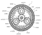
- FIG. 2 is a sectional view taken along line AA and BB in FIG. 1 (reference numerals are shown in parentheses).
- FIG. 1 is a vertical cross-sectional view of a compact speed reducer according to an embodiment of the present invention.
- FIG. 2 is a cross-sectional view taken along the line AA and the line BB in FIG. 1 (reference numerals are shown in parentheses).
- the cross section by the surface containing the central axis J1 of the small reduction gear 1 (hereinafter also simply referred to as a reduction gear) is shown.
- the upper side in FIG. 1 is referred to as “upper” or “upper”, and the lower side is referred to as “lower” or “lower”.
- the up-down direction which is the direction in which the central axis J1 faces, is also referred to as “axial direction”.
- the circumferential direction centered on the central axis J1 is simply referred to as “circumferential direction”
- the radial direction centered on the central axis J1 is simply referred to as “radial direction”.
- the speed reducer 1 is a speed reducer 1 that decelerates the power from the input shaft 31 and transmits the power to the output shaft 9.
- the speed reducer 1 is located on a substantially cylindrical casing 2 and an inner peripheral surface 2 a of the casing 2. Together with the annular first internal gear 5, the input gear 33 connected to the input shaft 31, the first rotary shaft portion 41 coaxially arranged with the input shaft 31 in the casing 2, and the first rotary shaft portion 41.
- a first planet carrier 42 that has a rotating sun gear 45 and is rotatable around a first rotation shaft portion 41, and an input gear 33 and a first internal gear 5 that are rotatably supported by the first planet carrier 42.
- a plurality of first planetary gears 44 meshing with each other and a second rotating body 6 rotatable by a sun gear 45 are provided.
- the speed reducer 1 includes a casing 2, an input unit 3, a first rotating body 4, a second rotating body 6, a first internal gear 5, a second internal gear 7, and an output. It includes the shaft 9 and the motor 10 having the input shaft 31 of the input unit 3 described above.
- the speed reducer 1 has a planetary gear mechanism having a two-stage structure including a first rotating body 4 and a second rotating body 6, and is formed to have an outer dimension of 5 mm in width, 5 mm in depth, and 20 mm in height or less, for example. ..
- the motor 10 serves as a drive source of a structure (not shown) on which the speed reducer 1 is mounted, that is, a power source.
- a structure not particularly limited, and a small camera can be given as an example.
- various motors are appropriately selected according to the usage of the structure.
- the motor 10 includes a motor housing 11 and a stator and a rotor (not shown) housed in the motor housing 11. In the motor 10, when the rotor rotates with respect to the stator fixed in the motor housing 11, the input shaft 31 connected to the rotor rotates. That is, the input shaft 31 is also the motor shaft of the motor 10 that is rotationally driven about the central axis J1.
- the motor housing 11 is a casing that internally houses components such as a stator and a rotor.
- the motor housing 11 has a cylindrical portion 12 and a bulging portion 13, which are integrally formed.
- the tubular portion 12 is a portion that is formed in a tubular shape that extends in the vertical direction, and is formed to extend radially inward from a cylindrical portion 12a that is formed in a substantially cylindrical shape and an upper edge portion of the cylindrical portion 12a. And an upper wall portion 12b.
- the upper wall portion 12b is formed in an annular shape.
- the bulging portion 13 has a cylindrical portion 13a formed so as to extend in a cylindrical shape upward from the inner peripheral edge of the upper wall portion 12b, and a cover portion 13b that covers the upper opening of the cylindrical portion 13a.
- An insertion hole through which the input shaft 31 is inserted is formed at the center of the cover portion 13b.
- the outer diameter of the cylindrical portion 13a is smaller than the outer diameter of the cylindrical portion 12a of the cylindrical portion 12.
- the casing 2 is arranged and fixed on the upper side of the motor 10.
- the casing 2 has a substantially cylindrical shape centered on the central axis J1.
- Between the inner peripheral surface 2a of the casing 2 and the outer peripheral surface of the cylindrical portion 13a of the bulging portion 13 in a state where the speed reducer 1 is assembled and the bulging portion 13 of the motor 10 is housed in the casing 2. Is formed with a predetermined gap.
- a holder 15, which will be described in detail later, is sandwiched in this gap.
- the casing 2 is positioned with respect to the motor 10 via the holder 15 so as to be coaxial with the central axis J1.
- the input unit 3 Inside the casing 2, the input unit 3, the first rotating body 4, a part of the second rotating body 6, the first internal gear 5, and the second internal gear 7 are housed.
- the second rotating body 6 side is the upper side and the first rotating body 4 side is the lower side along the central axis J1, but the direction of the central axis J1 does not necessarily have to coincide with the gravity direction. ..
- the gear ratio between the first rotating body 4 and the second rotating body 6 is appropriately set depending on the intended use of the structure. Thereby, the power from the motor 10 can be decelerated and output from the output shaft 9.
- the input unit 3 includes an input shaft 31 and an input gear 33.
- the input shaft 31 can rotate around the central axis J1 together with the rotor when the motor 10 is rotationally driven.
- the input shaft 31 has a substantially cylindrical shape or a substantially cylindrical shape.
- An input gear 33 is concentrically fixed to the outer peripheral portion of the input shaft 31. As a result, the input gear 33 can rotate around the central axis J1 together with the input shaft 31.
- the method for fixing the input gear 33 to the input shaft 31 is not particularly limited, and for example, a fixing method using a key and a key groove can be used.
- the input shaft 31 and the input gear 33 are configured separately from each other in the illustrated configuration, the invention is not limited to this, and may be configured by one gear member integrally formed, for example.
- the input gear 33 is a spur gear having a plurality of teeth 331 (hereinafter, referred to as “outer peripheral teeth 331”) protruding on the outer peripheral portion thereof.
- the first rotating body 4 includes a first rotating shaft portion 41, a first planetary carrier 42, a plurality of first planetary shaft members 43, a plurality of first planetary gears 44, and a sun gear 45.
- the first rotating shaft portion 41, the first planetary carrier 42, and the plurality of first planetary shaft members 43 are support bodies that support the respective first planetary gears 44 and the sun gears 45.
- this support may further include another member.
- the first rotating shaft portion 41, the first planetary carrier 42, and the plurality of first planetary shaft members 43 are configured as one gear member by integral molding in the present embodiment, but the invention is not limited to this, and, for example, one another. It may be configured as a separate body, and may be configured as a connected body in which these separate bodies are connected.
- the first rotation shaft portion 41 has a substantially cylindrical shape or a substantially columnar shape, and its central axis coincides with the central axis J1. Further, the first rotation shaft portion 41 is arranged above the input shaft 31 of the input unit 3. A disk-shaped first planetary carrier 42 is arranged concentrically with the first rotation shaft portion 41 below the first rotation shaft portion 41. That is, the first rotation shaft portion 41 is arranged so as to project upward at the center of the disk-shaped first planet carrier 42.
- first planetary shaft members 43 are arranged on the outer peripheral side of the first planetary carrier 42, that is, at positions eccentric from the central axis J1 (first rotation shaft portion 41). ..
- the plurality of first planetary shaft members 43 have the same substantially cylindrical shape, and are arranged with their longitudinal directions oriented along the central axis J1 (hereinafter, also referred to as “along the central axis J1”). There is.
- the number of the first planetary shaft members 43 arranged is three in the configuration shown in FIG. 2, but is not limited to this, and may be two or four or more.
- the first planetary shaft members 43 are arranged at equal angular intervals around the central axis J1. For example, as shown in FIG.
- first planetary shaft J2 when the number of arranged first planetary shaft members 43 is three, these first planetary shaft members 43 are arranged at 120° intervals around the central axis J1.
- the central axis of each first planetary shaft member 43 is referred to as "first planetary shaft J2".
- a first planetary gear 44 is rotatably (rotatably) supported on each first planetary shaft member 43. As a result, each first planetary gear 44 can rotate about the first planetary axis J2, that is, can rotate on its axis. Further, each of the first planetary gears 44 can rotate, that is, revolve around the central axis J1. As described above, each first planetary gear 44 is a planetary gear (also referred to as “P gear”) that rotates about the first planetary axis J2 and revolves around the central axis J1. Each first planetary gear 44 is a spur gear having a plurality of teeth 441 (hereinafter, referred to as “outer peripheral teeth 441”) protruding on the outer peripheral portion thereof. The first planetary gears 44 are arranged radially outward of the input gear 33 along the circumferential direction thereof, and the outer peripheral teeth 441 mesh with (engage with) the outer peripheral teeth 331 of the input gear 33.
- the sun gear 45 is concentrically fixed to the outer peripheral portion of the first rotating shaft portion 41. Thereby, the sun gear 45 can rotate around the central axis J1 together with the first rotation shaft portion 41.
- the method for fixing the sun gear 45 to the first rotating shaft portion 41 is not particularly limited, and for example, a fixing method using a key and a key groove can be used.
- the sun gear 45 is a spur gear having a plurality of teeth 451 (hereinafter, referred to as “outer peripheral teeth 451”) protruding on the outer peripheral portion thereof.
- the first rotary shaft portion 41 and the sun gear 45 are configured separately from each other in the illustrated configuration, the invention is not limited to this, and for example, they may be configured by one gear member integrally molded. Good.
- first rotary shaft portion 41, the first planetary carrier 42, the plurality of first planetary shaft members 43, and the sun gear 45 may be configured by one gear member formed by integral molding, and such a gear member is referred to as “C”. Also called "gear”.
- the first internal gear 5 has an annular shape with the central axis J1 as the central axis.
- the first internal gear 5 is arranged and fixed inside the casing 2 concentrically with the casing 2.
- the fixing method is not particularly limited, and for example, a fixing method by fitting can be used. In this case, intermediate fitting is preferred.
- the first internal gear 5 is an internal gear having a plurality of teeth 51 (hereinafter referred to as “inner peripheral teeth 51”) protruding on the inner peripheral portion thereof.
- the inner peripheral teeth 51 mesh with the outer peripheral teeth 441 of each first planetary gear 44 at different positions in the circumferential direction.
- the second rotating body 6 is arranged above the first rotating body.
- the second rotating body 6 includes a second rotating shaft portion 61, a second planet carrier 62, a plurality of second planetary shaft members 63, and a plurality of second planetary gears 64.
- the second rotating shaft portion 61, the second planet carrier 62, and the plurality of second planetary shaft members 63 are support bodies that support the respective second planetary shaft members 63.
- this support may further include another member.
- the second rotating shaft portion 61, the second planetary carrier 62, and the plurality of second planetary shaft members 63 are configured as one gear member by integral molding in the present embodiment, but are not limited to this, and for example, they may be mutually It may be configured as a separate body, and may be configured as a connected body in which these separate bodies are connected.
- the second rotating shaft portion 61 has a substantially cylindrical shape or a substantially columnar shape, and its central axis coincides with the central axis J1 like the first rotating shaft portion 41. Further, the second rotating shaft portion 61 projects upward from the upper surface of the casing 2 to the outside of the casing 2.
- a disk-shaped second planet carrier 62 is arranged concentrically with the second rotating shaft portion 61 below the second rotating shaft portion 61. That is, the second rotation shaft portion 61 is arranged so as to project upward at the center of the disk-shaped second planet carrier 62.
- a plurality of second planetary shaft members 63 are arranged on the outer peripheral side of the second planetary carrier 62, that is, at a position eccentric from the central axis J1 (second rotating shaft portion 61). ..
- the plurality of second planetary shaft members 63 have the same substantially cylindrical shape, and are arranged with their longitudinal directions oriented along the central axis J1 (along the central axis J1). Note that the number of the second planetary shaft members 63 arranged is three in the configuration shown in FIG. 2, but is not limited to this, and may be two or four or more, and particularly the first planetary shaft member 43. It is preferable that the number is the same as the number of arrangements.
- the second planetary shaft members 63 are arranged at equal angular intervals around the central axis J1. For example, as shown in FIG. 2, when the number of the second planetary shaft members 63 arranged is three, these second planetary shaft members 63 are arranged around the central axis J1 at 120° intervals. In the following description, the central axis of each second planetary shaft member 63 is referred to as "second planetary shaft J3".
- a second planetary gear 64 is rotatably (rotatably) supported on each second planetary shaft member 63. As a result, each second planetary gear 64 can rotate about the second planetary axis J3, that is, can rotate on its axis. In addition, each second planetary gear 64 can rotate, that is, revolve around the central axis J1. As described above, each second planetary gear 64 is a planetary gear (also referred to as “P gear”) that rotates about the second planetary axis J3 and revolves around the central axis J1. Each second planetary gear 64 is a spur gear having a plurality of teeth 641 (hereinafter referred to as “outer peripheral teeth 641”) protruding on the outer peripheral portion thereof. The second planetary gears 64 are arranged radially outward of the sun gear 45 and along the circumferential direction thereof, and the outer peripheral teeth 641 mesh (engage) with the outer peripheral teeth 451 of the sun gear 45.
- the second internal gear 7 has an annular shape with the central axis J1 as the central axis.
- the second internal gear 7 is arranged inside the casing 2, above the first internal gear 5, and axially separated from the first internal gear 5. Further, the second internal gear 7 is arranged and fixed concentrically with the casing 2.
- the fixing method is not particularly limited, and for example, a fixing method by fitting can be used. In this case, intermediate fitting is preferred.
- the second internal gear 7 is an internal gear having a plurality of teeth 71 (hereinafter referred to as "inner peripheral teeth 71") protruding on the inner peripheral portion thereof.
- the inner peripheral teeth 71 mesh with the outer peripheral teeth 641 of each second planetary gear 64 at different positions in the circumferential direction.
- the output shaft 9 is connected (connected) to the upper portion of the second rotating shaft portion 61 outside the casing 2 and can rotate around the central axis J1 together with the second rotating shaft portion 61.
- the output shaft 9 has a substantially cylindrical shape or a substantially cylindrical shape, and its outer diameter is the same as the outer diameter of the second rotating shaft portion 61.
- the holder 15 is a substantially cylindrical member, and is used to position the casing 2 and the internal gears 5 and 7 with respect to the motor 10 so as to be coaxial with the central axis J1.
- the holder 15 has a portion (cylindrical portion 15a) formed in a substantially annular shape, and the portion is located between the casing 2 and the motor 10 in a radial direction which is a direction perpendicular to a direction in which the central axis J1 extends. It is sandwiched and held.
- the holder 15 has a cylindrical portion 15a formed in a cylindrical shape and an annular portion 15b formed so as to extend inward from the upper end edge of the cylindrical portion 15a, and these are integrally formed.
- the inner diameter of the cylindrical portion 15a is substantially the same as the outer diameter of the cylindrical portion 13a of the bulging portion 13.
- the outer diameter of the cylindrical portion 15a is substantially the same as the inner diameter of the inner peripheral surface 2a of the casing 2.
- the gear ratio between the first rotating body 4 and the second rotating body 6 is set within a predetermined range.
- the motor 10 operates, its power is transmitted to the input gear 33 via the input shaft 31.
- the input gear 33 rotates around the central axis J1 in the arrow ⁇ 1 direction.
- the rotational force of the input gear 33 is transmitted to each first planetary gear 44 that meshes with the input gear 33.
- each first planetary gear 44 can rotate around the first planetary axis J2 in the direction of the arrow ⁇ 2, that is, rotate on its axis.
- Each first planetary gear 44 also meshes with the first internal gear 5 fixed to the casing 2.
- the rotational force thereof can be transmitted to the first internal gear 5, so that the arrow about the central axis J1 is provided. It can also rotate in the ⁇ 3 direction, that is, it can revolve. By this revolution, the sun gear 45 can be rotated around the central axis J1 in the arrow ⁇ 1 direction.
- each second planetary gear 64 meshes with the sun gear 45. As a result, when the sun gear 45 rotates in the direction of arrow ⁇ 1, the rotational force is transmitted to each second planetary gear 64. By this transmission, as shown in FIG. 2, each two-planetary gear 64 can rotate around the second planetary axis J3 in the arrow ⁇ 2 direction, that is, rotate on its axis.
- each second planetary gear 64 is also meshed with the second internal gear 7 fixed to the casing 2.
- each second planetary gear 64 can transmit its rotational force to the second internal gear 7 when the second planetary gear 64 rotates in the direction of the arrow ⁇ 2, and thus the arrow about the central axis J1. It can rotate in the ⁇ 3 direction, that is, can revolve. By this revolution, the output shaft 9 can be rotated around the central axis J1 in the same direction as the arrow ⁇ 1 direction.
- the direction along the central axis J1 means a direction substantially parallel to the central axis J1 (axial direction), and does not need to be strictly parallel to the axial direction. That is, the first planetary axis J2 and the second planetary axis J3 may be parallel to the central axis J1 or may be inclined by a small angle with respect to the central axis J1.
- the small reduction gear 1 is formed with a volume equal to or smaller than the above-described external dimensions (width 5 mm, depth 5 mm, height 20 mm), and the first planetary gear 44 of the first rotating body 4 and the second planetary gear 44.
- the second planetary gear 64 of the rotating body has a module of, for example, 0.2 to 0.05 mm. This makes it possible to obtain a microminiature molded part. Further, by using such a component, it becomes possible to manufacture a precise speed reducer having the above-mentioned external dimensions and suitable for mounting on other small devices.
- the speed reducer according to the present embodiment was developed to meet such market demands, and as described above, the external dimensions are extremely small, and the resin parts such as gears used in the speed reducer are also extremely thin and small. Further, the small reducer 1 according to the present embodiment is designed to output a predetermined torque using a small motor and has a large reduction ratio, so that the load on the motor is large and the amount of heat generated is relatively large.
- NTB935 manufactured by Otsuka Chemical Co., Ltd. is adopted as the resin composition used for the input gear 33, the plurality of first planetary gears 44, and the holder 15 of the compact reduction gear 1 according to the present embodiment.
- This NTB935 uses a polyamide resin as a crystalline resin.
- As the filler 15% by weight of wollastonite and 25% by weight of potassium titanate fiber are used.
- the wollastonite is a silicate mineral represented by the chemical formula CaSiO 3 .
- NTB935 The characteristics of NTB935 are (1) low water absorption, (2) heat resistance, (3) high strength, and (4) high dimensional accuracy.
- NTB935 is a material having excellent heat resistance, and as a result of intensive studies by the inventors of the present application, by selecting this material, a gear of a reduction gear which is extremely small and has excellent heat resistance can be made of a resin material. Was able to be manufactured.
- NTB935 has low water absorption in addition to heat resistance as described above. It is preferable to use such a resin for the holder 15 because the relative positional relationship between the casing 11 and the motor 10 can be maintained.
- NTB935 is adopted as the resin material used for the input gear 33, the plurality of first planetary gears 44, and the holder 15.
- the filler contained in the resin composition contains wollastonite and an inorganic whisker as a predetermined functional expression component.
- the heat resistance of the input gear 33, the plurality of first planetary gears 44, and the holder 15 is improved, so that it is possible to provide a speed reducer having excellent heat resistance.
- the total amount of wollastonite and the amount of inorganic whiskers in the resin composition is preferably 30 to 50% by weight. This makes it possible to provide a speed reducer having excellent heat resistance.
- the amount of wollastonite in the resin composition is preferably 10 to 20% by weight, and the amount of inorganic whiskers is preferably 20 to 30% by weight. This makes it possible to provide a speed reducer having excellent heat resistance.
- the amount of wollastonite is 15% by weight and the amount of inorganic whiskers is 25% by weight. This makes it possible to provide a speed reducer having excellent heat resistance.
- the present invention is not limited to this, and other crystalline resins may be used.
- a lubricant may be added to the resin composition used for the input gear 33 and the plurality of first planetary gears 44.
- the amount of the lubricant in the above resin composition is preferably 1 to 10% by weight, more preferably 1 to 5% by weight.
- Examples of the lubricant include fluorine resin and olefin resins such as polyolefin.
- fluorine resin include polytetrafluoroethylene (PTFE), perfluoroalkoxyalkane (PFA), ethylene-tetrafluoroethylene copolymer (ETFE), perfluoroethylene-propene copolymer (FEP), polyvinylidene fluoride (PVDF), Examples thereof include polychlorotrifluoroethylene (PCTFE) and ethylene-chlorotrifluoroethylene copolymer (ECTFE).
- PTFE polytetrafluoroethylene
- PFA perfluoroalkoxyalkane
- ETFE ethylene-tetrafluoroethylene copolymer
- FEP perfluoroethylene-propene copolymer
- PVDF polyvinylidene fluoride
- PCTFE polychlorotrifluoroethylene
- ECTFE ethylene-chlorotrifluoroethylene copo
- the planet gear is described as an example of the second rotating body, but the second rotating body is not limited to this, and the second rotating body may be a gear such as a spur gear.
- NTB 935 is used for the input gear 33, the plurality of first planetary gears 44, and the holder 15 has been described, but the present invention is not limited to this.
- NTB935 may be used for the holder 15, and other resin materials may be used for the input gear 33 and the plurality of first planetary gears 44.
- NTB935 may be used for one of the input gear 33 and the plurality of first planetary gears 44. Since the wollastonite contained in NTB935 is a relatively hard material, the parts containing wollastonite will be hard, but if other materials also contain wollastonite, they can be scraped by rubbing against each other. There is a nature. In this respect, it is preferable to use NTB935 for one of the input gear 33 and the plurality of first planetary gears 44 from the viewpoint of wear resistance. Further, in this case, it is preferable to use NTB935 for the input gear 33.
- the input gear 33 fixed to the rotating shaft of the motor which generates a large amount of heat, is required to have higher heat resistance than the first planetary gear 44 to which the heat of the motor is transferred via the input gear 33. is there. That is, by using NTB935 for the input gear 33 and using a resin material other than that for the plurality of first planetary gears 44, it is possible to provide a speed reducer excellent in both heat resistance and wear resistance.
- the speed reducer according to the present invention can be used in various devices such as small cameras, robots, and other small and thin devices.
- the speed reducer according to the present invention can also be used for other purposes.
Landscapes
- Chemical & Material Sciences (AREA)
- Health & Medical Sciences (AREA)
- Chemical Kinetics & Catalysis (AREA)
- Medicinal Chemistry (AREA)
- Polymers & Plastics (AREA)
- Organic Chemistry (AREA)
- Engineering & Computer Science (AREA)
- General Engineering & Computer Science (AREA)
- Mechanical Engineering (AREA)
- Retarders (AREA)
Abstract
モータの回転による入力軸からの動力を減速して出力軸に伝達する減速機において、略環状に形成された部分を有し、当該部分が、入力軸の中心軸が延びる方向に対して垂直な方向において、減速機のケーシングとモータとの間に挟まれて保持されるホルダは、結晶性樹脂と充填剤とを含有する樹脂組成物を用いて形成され、充填剤には、ワラストナイトと、所定の機能性発現成分としての無機ウィスカとが含まれる。
Description
本発明は、減速機、特に小型、薄型の電子機器等に搭載される小型減速機に関する。
従来より、遊星歯車機構を用いた減速装置が知られている(例えば、特許文献1参照)。この減速装置では、遊星ギアを金属射出成形(MIM)法で製造し、添加剤を含有する樹脂組成物を用いて出力ギアおよび固定ギアを製造している。
しかしながら、MIM法でギアを製造する場合、得られるギアの寸法精度が低く、歩留まりを高めることが困難である。一方、樹脂組成物を用いてギアを製造する場合、用いる材料によっては十分な耐熱性を得られない場合がある。
本発明は、上記課題に鑑みなされたものであり、その目的は、耐熱性に優れた減速機を提供することである。
本願の例示的な発明は、モータの回転による入力軸からの動力を減速して出力軸に伝達する減速機であって、略筒状のケーシングと、前記ケーシングの内周面に位置する環状の第1インターナルギアと、前記入力軸に接続された入力ギアと、前記ケーシング内において前記入力軸と同軸に配置された第1回転軸部と、前記第1回転軸部とともに回転する太陽ギアを有し、前記第1回転軸部を中心に回転可能な第1遊星キャリアと、前記第1遊星キャリアに自転可能に支持され、前記入力ギアと前記第1インターナルギアとに噛み合う複数の第1遊星ギアと、前記太陽ギアにより回転可能な第2回転体と、略環状に形成された部分を有し、当該部分が、前記入力軸の中心軸が延びる方向に対して垂直な方向において前記ケーシングと前記モータとの間に挟まれて保持されるホルダと、を備え、前記ホルダは、結晶性樹脂と充填剤とを含有する樹脂組成物を用いて形成され、前記充填剤には、ワラストナイトと、所定の機能性発現成分としての無機ウィスカとが含まれる。
本願の例示的な発明によれば、耐熱性に優れた減速機を提供することができる。
以下、本発明に係る実施形態について添付図面を参照して詳細に説明する。図1は、本発明の一実施形態に係る小型減速機の縦断面図である。図2は、図1中のA-A線断面図およびB-B線断面図(符号についてはかっこ書きで記載)である。
なお、図1では、小型減速機1(以降において単に減速機ともいう)の中心軸J1を含む面による断面を示す。また、以下では、説明の都合上、図1中の上側を「上」または「上方」と言い、下側を「下」または「下方」と言う。
また、以下の説明では、中心軸J1が向く方向である上下方向を「軸方向」とも呼ぶ。また、以下の説明では、中心軸J1を中心とする周方向を単に「周方向」といい、中心軸J1を中心とする径方向を単に「径方向」という。
本実施形態に掛かる減速機1は、入力軸31からの動力を減速して出力軸9に伝達する減速機1であって、略筒状のケーシング2と、ケーシング2の内周面2aに位置する環状の第1インターナルギア5と、入力軸31に接続された入力ギア33と、ケーシング2内において入力軸31と同軸に配置された第1回転軸部41と、第1回転軸部41とともに回転する太陽ギア45を有し、第1回転軸部41を中心に回転可能な第1遊星キャリア42と、第1遊星キャリア42に自転可能に支持され、入力ギア33と第1インターナルギア5とに噛み合う複数の第1遊星ギア44と、太陽ギア45により回転可能な第2回転体6と、を備えている。
図1に示すように、減速機1は、ケーシング2と、入力部3と、第1回転体4と、第2回転体6と、第1インターナルギア5と、第2インターナルギア7と、出力軸9と、上述した入力部3の入力軸31を有するモータ10とを含む。
減速機1は、第1回転体4と第2回転体6との2段構成の遊星ギア機構を有し、例えば外形寸法が幅5mm、奥行き5mm、高さ20mmの容積以下に形成されている。
<モータ>
モータ10は、減速機1が搭載される構造体(図示せず)の駆動源、すなわち、動力源となる。なお、構造体としては、特に限定されず、例えば小型カメラが挙げられる。また、モータ10としては、例えば、構造体の使用用途に応じて、各種のモータが適宜選択される。モータ10は、モータハウジング11と、モータハウジング11に収容されたステータ及びロータ(図示省略)とを備えている。モータ10では、モータハウジング11内に固定されたステータに対してロータが回転することにより、ロータに接続された入力軸31が回転する。すなわち、入力軸31は、中心軸J1を回転中心として回転駆動するモータ10のモータ軸でもある。
モータハウジング11は、内部にステータ及びロータ等の部品を収容するケーシングである。モータハウジング11は、筒部12及び膨出部13を有し、これらが一体に形成されている。
筒部12は、上下方向に伸びる筒状に形成された部分であって、略円筒状に形成された円筒部12aと、円筒部12aの上側の縁部から径方向内側へ延びるように形成された上壁部12bとを有している。上壁部12bは、円環状に形成されている。
膨出部13は、上壁部12bの内周縁から上方へ円筒状に延びるように形成された円筒部13aと、円筒部13aの上側の開口を覆うカバー部13bとを有している。カバー部13bの中心には、入力軸31が挿通する挿通孔が形成されている。円筒部13aの外径は、筒部12の円筒部12aの外径よりも小さい。
<ケーシング>
モータ10の上側には、ケーシング2が配置、固定されている。ケーシング2は、中心軸J1を中心とする略円筒状をなす。減速機1が組み立てられて、モータ10の膨出部13がケーシング2内に収容された状態において、ケーシング2の内周面2aと、膨出部13の円筒部13aの外周面との間には、所定の間隔の隙間が形成される。この隙間には、詳しくは後述するホルダ15が挟まれた状態となっている。これにより、ケーシング2は、モータ10に対してホルダ15を介して中心軸J1で同軸状となるように位置決めされている。
ケーシング2の内部には、入力部3、第1回転体4、第2回転体6の一部、第1インターナルギア5、および第2インターナルギア7が収容される。なお、図1中では、中心軸J1に沿って第2回転体6側を上側、第1回転体4側を下側としているが、中心軸J1の向きは必ずしも重力方向と一致させる必要はない。また、第1回転体4と第2回転体6とのギア比は、構造体の使用用途により適宜設定される。これにより、モータ10からの動力を減速して、出力軸9から出力することができる。
<入力部>
入力部3は、入力軸31と、入力ギア33とを含む。
入力軸31は、モータ10が回転駆動することにより、ロータとともに中心軸J1回りに回転することができる。入力軸31は、略円筒状または略円柱状である。
入力軸31の外周部には、入力ギア33が同心的に固定されている。これにより、入力ギア33は、入力軸31とともに中心軸J1回りに回転することができる。入力軸31に対する入力ギア33の固定方法としては、特に限定されず、例えば、キーとキー溝とを用いた固定方法を用いることができる。また、入力軸31と入力ギア33とは、図示の構成では互いに別体で構成されているが、これに限定されず、例えば、一体成形による1つのギア部材で構成されていてもよい。
図2に示すように、入力ギア33は、その外周部に突出した複数の歯331(以下、「外周歯331」という)を有する平歯車である。
<第1回転体>
第1回転体4は、第1回転軸部41と、第1遊星キャリア42と、複数の第1遊星軸部材43と、複数の第1遊星ギア44と、太陽ギア45とを含む。
第1回転体4では、第1回転軸部41、第1遊星キャリア42および複数の第1遊星軸部材43は、各第1遊星ギア44および太陽ギア45を支持する支持体である。この支持体は、第1回転軸部41、第1遊星キャリア42および複数の第1遊星軸部材43の他に、さらに別の部材を含んでもよい。
第1回転軸部41、第1遊星キャリア42および複数の第1遊星軸部材43は、本実施形態では一体成形により1つのギア部材で構成されているが、これに限定されず、例えば、互いに別体で構成し、これら別体同士が連結された連結体で構成されていてもよい。
第1回転軸部41は、略円筒状または略円柱状をなし、その中心軸が中心軸J1に一致している。また、第1回転軸部41は、入力部3の入力軸31よりも上側に配置されている。
第1回転軸部41の下部には、円盤状をなす第1遊星キャリア42が第1回転軸部41と同心的に配置されている。すなわち、円盤状をなす第1遊星キャリア42の中心部には、第1回転軸部41が上方に向かって突出して配置されている。
第1遊星キャリア42の下部には、第1遊星キャリア42の外周側、すなわち、中心軸J1(第1回転軸部41)から偏心した位置に複数の第1遊星軸部材43が配置されている。複数の第1遊星軸部材43は、同様の略円柱状をなし、その長手方向が中心軸J1に沿う方向を向いて(以下、「中心軸J1に沿って」とも記載する。)配置されている。
なお、第1遊星軸部材43の配置数は、図2に示す構成では3つであるが、これに限定されず、2つまたは4つ以上であってもよい。また、これらの第1遊星軸部材43は、中心軸J1周りに等角度間隔に配置されている。例えば、図2に示すように、第1遊星軸部材43の配置数が3つの場合、これらの第1遊星軸部材43は、中心軸J1周りに120°間隔に配置されている。以下の説明では、各第1遊星軸部材43の中心軸を「第1遊星軸J2」と呼ぶ。
各第1遊星軸部材43には、第1遊星ギア44が回転可能(回転自在)に支持されている。これにより、各第1遊星ギア44は、第1遊星軸J2を回転中心として回転すること、すなわち、自転することができる。また、各第1遊星ギア44は、中心軸J1を回転中心として回転すること、すなわち、公転することができる。このように、各第1遊星ギア44は、第1遊星軸J2回りに自転し、中心軸J1回りに公転する遊星ギア(「Pギア」とも呼ぶ。)となっている。
各第1遊星ギア44は、その外周部に突出した複数の歯441(以下、「外周歯441」という)を有する平歯車である。そして、各第1遊星ギア44は、入力ギア33の径方向外側に、その周方向に沿って配置され、外周歯441が入力ギア33の外周歯331に噛み合って(係合して)いる。
第1回転軸部41の外周部には、太陽ギア45が同心的に固定されている。これにより、太陽ギア45は、第1回転軸部41とともに中心軸J1回りに回転することができる。なお、第1回転軸部41に対する太陽ギア45の固定方法としては、特に限定されず、例えば、キーとキー溝とを用いた固定方法を用いることができる。太陽ギア45は、その外周部に突出した複数の歯451(以下、「外周歯451」という)を有する平歯車である。
また、第1回転軸部41と太陽ギア45とは、図示の構成では互いに別体で構成されているが、これに限定されず、例えば、一体成形による1つのギア部材で構成されていてもよい。したがって、第1回転軸部41、第1遊星キャリア42、複数の第1遊星軸部材43および太陽ギア45は、一体成形による1つのギア部材で構成されていてもよく、かかるギア部材を「Cギア」とも呼ぶ。
<第1インターナルギア>
第1インターナルギア5は、中心軸J1を中心軸とする環状をなす。第1インターナルギア5は、ケーシング2の内側にケーシング2と同心的に配置、固定されている。この固定方法としては、特に限定されず、例えば、嵌め合いによる固定方法を用いることができる。この場合、中間嵌めが好ましい。
図2に示すように、第1インターナルギア5は、その内周部に突出した複数の歯51(以下、「内周歯51」という)を有する内歯車である。内周歯51は、その周方向の異なる位置で、各第1遊星ギア44の外周歯441と噛み合っている。
<第2回転体>
第2回転体6は、第1回転体の上側に配置されている。第2回転体6は、第2回転軸部61と、第2遊星キャリア62と、複数の第2遊星軸部材63と、複数の第2遊星ギア64とを含む。
第2回転体6では、第2回転軸部61と、第2遊星キャリア62および複数の第2遊星軸部材63は、各第2遊星軸部材63を支持する支持体である。この支持体は、第2回転軸部61と、第2遊星キャリア62および複数の第2遊星軸部材63の他に、さらに別の部材を含んでもよい。
第2回転軸部61、第2遊星キャリア62および複数の第2遊星軸部材63は、本実施形態では一体成形により1つのギア部材で構成されているが、これに限定されず、例えば、互いに別体で構成し、これら別体同士が連結された連結体で構成されていてもよい。
第2回転軸部61は、略円筒状または略円柱状をなし、第1回転軸部41と同様にその中心軸が中心軸J1に一致している。また、第2回転軸部61は、ケーシング2の上面から上方に向かってケーシング2の外側へと突出する。
第2回転軸部61の下部には、円盤状をなす第2遊星キャリア62が第2回転軸部61と同心的に配置されている。すなわち、円盤状をなす第2遊星キャリア62の中心部には、第2回転軸部61が上方に向かって突出して配置されている。
第2遊星キャリア62の下部には、第2遊星キャリア62の外周側、すなわち、中心軸J1(第2回転軸部61)から偏心した位置に複数の第2遊星軸部材63が配置されている。複数の第2遊星軸部材63は、同様の略円柱状をなし、その長手方向が中心軸J1に沿う方向を向いて(中心軸J1に沿って)配置されている。
なお、第2遊星軸部材63の配置数は、図2に示す構成では3つであるが、これに限定されず、2つまたは4つ以上であってもよく、特に第1遊星軸部材43の配置数と同数であるのが好ましい。
また、これらの第2遊星軸部材63は、中心軸J1周りに等角度間隔で配置されている。例えば、図2に示すように、第2遊星軸部材63の配置数が3つの場合、これらの第2遊星軸部材63は、中心軸J1周りに120°間隔で配置される。以下の説明では、各第2遊星軸部材63の中心軸を「第2遊星軸J3」と呼ぶ。
各第2遊星軸部材63には、第2遊星ギア64が回転可能(回転自在)に支持されている。これにより、各第2遊星ギア64は、第2遊星軸J3を回転中心として回転すること、すなわち、自転することができる。また、各第2遊星ギア64は、中心軸J1を回転中心として回転すること、すなわち、公転することができる。このように、各第2遊星ギア64は、第2遊星軸J3回りに自転し、中心軸J1回りに公転する遊星ギア(「Pギア」とも呼ぶ。)となっている。
各第2遊星ギア64は、その外周部に突出した複数の歯641(以下、「外周歯641」という)を有する平歯車である。そして、各第2遊星ギア64は、太陽ギア45の径方向外側に、その周方向に沿って配置され、外周歯641が太陽ギア45の外周歯451に噛み合って(係合して)いる。
<第2インターナルギア>
第2インターナルギア7は、中心軸J1を中心軸とする環状をなす。第2インターナルギア7は、ケーシング2の内側に、第1インターナルギア5よりも上側であって、軸方向に第1インターナルギア5と離れて配置されている。
また、第2インターナルギア7は、ケーシング2と同心的に配置、固定されている。この固定方法としては、特に限定されず、例えば、嵌め合いによる固定方法を用いることができる。この場合、中間嵌めが好ましい。
第2インターナルギア7は、その内周部に突出した複数の歯71(以下「内周歯71」という)を有する内歯車である。内周歯71は、その周方向の異なる位置で、各第2遊星ギア64の外周歯641と噛み合っている。
<出力軸>
出力軸9は、ケーシング2の外側で第2回転軸部61の上部に連結され(接続され)、第2回転軸部61とともに中心軸J1回りに回転することができる。出力軸9は、略円筒状または略円柱状をなし、その外径が第2回転軸部61の外径と同じである。
<ホルダ>
ホルダ15は、略筒状の部材であって、中心軸J1で同軸状となるように、モータ10に対してケーシング2及び各インターナルギア5,7を位置決めするためのものである。ホルダ15は、略環状に形成された部分(円筒部15a)を有し、当該部分が、中心軸J1が延びる方向に対して垂直な方向である径方向においてケーシング2とモータ10との間に挟まれて保持されている。ホルダ15は、円筒状に形成された円筒部15aと、円筒部15aの上端縁から内側へ延びるように形成された円環部15bとを有し、これらが一体に形成されている。
円筒部15aの内径は、膨出部13の円筒部13aの外径と概ね同じである。また、円筒部15aの外径は、ケーシング2の内周面2aの内径と概ね同じである。そうすると、図1に示すように、減速機1を組み立てた状態において、ケーシング2の内周面2aとホルダ15の外周面との間に隙間が形成されず、且つホルダ15の内周面とモータ10の膨出部13の外周面との間に隙間が形成されない。これにより、ホルダ15をモータ10に対して周方向において位置決めできるとともに、ケーシング2をホルダ15に対して周方向において位置決めできる。言い換えれば、ホルダ15を介して、モータ10に対してケーシング2を位置決めできる。
<減速機の動作>
前述したように、減速機1は、第1回転体4と第2回転体6とのギア比が所定の範囲に設定されている。
まず、モータ10が作動することにより、その動力が入力軸31を介して入力ギア33に伝達される。これにより、図2に示すように、入力ギア33は、中心軸J1回りに矢印α1方向に回転する。
そして、入力ギア33に噛み合う各第1遊星ギア44には、入力ギア33の回転力が伝達される。これにより、図2に示すように、各第1遊星ギア44は、第1遊星軸J2回りに矢印α2方向に回転すること、すなわち、自転することができる。
また、各第1遊星ギア44は、ケーシング2に固定された第1インターナルギア5にも噛み合っている。これにより、図2に示すように、各第1遊星ギア44は、矢印α2方向に自転した際、その回転力を第1インターナルギア5に伝達することができ、よって、中心軸J1回りに矢印α3方向にも回転すること、すなわち、公転することができる。この公転により、太陽ギア45を中心軸J1回りに矢印β1方向に回転させることができる。
また、太陽ギア45には、各第2遊星ギア64が噛み合っている。これにより、太陽ギア45が矢印β1方向に回転した際、その回転力が各第2遊星ギア64に伝達される。そして、この伝達により、図2に示すように、各2遊星ギア64は、第2遊星軸J3回りに矢印β2方向に回転すること、すなわち、自転することができる。
また、各第2遊星ギア64は、ケーシング2に固定された第2インターナルギア7にも噛み合っている。これにより、図2に示すように、各第2遊星ギア64は、矢印β2方向に自転した際、その回転力を第2インターナルギア7に伝達することができ、よって、中心軸J1回りに矢印β3方向に回転する、すなわち、公転することができる。そして、この公転により、出力軸9を中心軸J1回りに矢印β1方向と同方向に回転させることができる。
以上のような力伝達により、出力軸9からは、減速された動力が出力されることとなる。
以上説明した構成において、中心軸J1に沿う方向とは、中心軸J1(軸方向)にほぼ平行な方向を意味しており、軸方向に厳密に平行である必要はない。すなわち、第1遊星軸J2および第2遊星軸J3は、中心軸J1に平行であってもよく、中心軸J1に対して小さい角度だけ傾斜してもよい。
<入力ギア、第1遊星ギア、及びホルダの材料について>
本実施形態に係る小型減速機1は、上述した外形寸法(幅5mm、奥行き5mm、高さ20mm)の容積以下に形成されており、第1回転体4の第1遊星ギア44、および第2回転体の第2遊星ギア64は、モジュールが例えば0.2~0.05mmである。これにより、超小型成形部品を得ることができる。また、このような部品を使用することで、上記の外形寸法を有し、他の小型機器への搭載に適した精密な減速機の製造が可能となる。
ところで、減速機1において、駆動源であるモータ10ではロータが高速で回転するため高温となりやすい。このように高温となりやすいモータ10のモータハウジング11を介して減速機1の部品、特に樹脂製の部品に熱が伝わると、その部品が変形し、減速機1としての信頼性が低下してしまうおそれが生じる。
一方、近年、製品に対する小型化の要求がますます厳しくなってきており、減速機にも小型化が求められている。本実施形態に係る減速機は、そのような市場の要求に応えるべく開発されたもので、上述した通り外形寸法は極めて小さく、減速機に用いられるギア等の樹脂部品も非常に薄く小さい。更に、本実施形態に係る小型減速機1は、小さなモータを用いて所定のトルクを出力できるように設計されていて減速比も大きいため、モータに掛かる負荷も大きく発熱量も比較的大きい。
この点につき、本実施形態に係る小型減速機1の入力ギア33、複数の第1遊星ギア44、及びホルダ15に用いられる樹脂組成物は、大塚化学株式会社製のNTB935が採用されている。このNTB935は、結晶性樹脂としてポリアミド系樹脂が用いられている。また、充填剤として、15重量%のワラストナイトと、25重量%のチタン酸カリウム繊維とが用いられている。なお、ワラストナイトとは、化学式CaSiO3で示される珪酸塩鉱物である。
NTB935の特徴は、(1)低吸水性を有する点、(2)耐熱性を有する点、(3)高強度である点、(4)寸法精度が高い点、である。特に、NTB935は、耐熱性に優れた材料であり、本願発明者が鋭意研究を重ねた結果、この材料を選定することで、非常に小型且つ耐熱性に優れた減速機のギアを、樹脂材料を用いて製造することができた。また、NTB935は上述のように耐熱性の他に吸水性が低い。このような樹脂をホルダ15に用いることで、モータ10に対するケーシング11の相対的な位置関係を維持することができるため、好ましい。具体的には、入力ギア33、複数の第1遊星ギア44、及びホルダ15にNTB935を用いた小型減速機1の動作耐久性試験を行った結果、30万回の動作に耐え、耐熱性の機能を満足する結果となった。
以上のように、本実施形態によれば、耐熱性に優れた減速機を提供できる。
<変形例>
上述した実施形態では、入力ギア33、複数の第1遊星ギア44、及びホルダ15に用いられる樹脂材料として、NTB935を採用した。しかし、これに限らない。具体的には、樹脂組成物に含まれる充填剤に、ワラストナイトと、所定の機能性発現成分としての無機ウィスカとが含有されていればよい。これにより、入力ギア33、複数の第1遊星ギア44、及びホルダ15の耐熱性が向上するため、耐熱性に優れた減速機を提供できる。
また、樹脂組成物におけるワラストナイトの量と無機ウィスカの量とを合計すると、30~50重量%となるのが好ましい。これにより、耐熱性に優れた減速機を提供できる。
また、前記樹脂組成物における、ワラストナイトの量は10~20重量%であり、無機ウィスカの量は20~30重量%であるのが好ましい。これにより、耐熱性に優れた減速機を提供できる。
また、前記樹脂組成物における、ワラストナイトの量は15重量%であり、無機ウィスカの量は25重量%であるのが好ましい。これにより、耐熱性に優れた減速機を提供できる。
また、上述した実施形態では、無機ウィスカとしてチタン酸カリウム繊維が用いられる例を挙げて説明したが、これに限らず、それ以外の無機ウィスカを用いても良い。
また、上述した実施形態では、結晶性樹脂としてポリアミド系樹脂が用いられる例を挙げて説明したが、これに限らず、それ以外の結晶性樹脂を用いても良い。
また、上述した実施形態において、入力ギア33及び複数の第1遊星ギア44に用いられる樹脂組成物に、滑剤を添加してもよい。上述した樹脂組成物における滑剤の量は、1~10重量%が好ましく、より好ましくは、1~5重量%である。このように入力ギア33及び複数の第1遊星ギア44の樹脂組成物に滑剤を添加することにより、入力ギア33と第1遊星ギア44との間の潤滑性を向上できるため、耐久性の観点で好ましい。
なお、滑剤としては、フッソ樹脂もしくはポリオレフィン (polyolefin)等のオレフィン系樹脂が挙げられる。フッソ樹脂としては、例えば、ポリテトラフルオロエチレン(PTFE)、パーフルオロアルコキシアルカン(PFA)、エチレン-テトラフルオロエチレンコポリマー(ETFE)、パーフルオロエチレン-プロペンコポリマー(FEP)、ポリフッ化ビニリデン(PVDF)、ポリクロロトリフルオロエチレン(PCTFE)、エチレン-クロロトリフロオロエチレンコポリマー(ECTFE)等が挙げられる。
また、上述した実施形態では、第2回転体として遊星ギアを例に挙げて説明したが、これに限らず、例えば第2回転体は平歯車等の歯車であってもよい。
また、上述した実施形態では、入力ギア33、複数の第1遊星ギア44、及びホルダ15に対してNTB935を用いる例を挙げて説明したが、これに限らない。例えばこれらの部品のうち、ホルダ15にNTB935を用い、入力ギア33及び複数の第1遊星ギア44に対してはその他の樹脂材料を用いても良い。
更には、入力ギア33及び複数の第1遊星ギア44の一方にNTB935を用いてもよい。NTB935に含まれるワラストナイトは比較的硬い材料であるため、ワラストナイトを含む部品は硬くなるものの、他の材料にもワラストナイトが含まれていると、互いに擦れ合って削れてしまう可能性がある。この点につき、入力ギア33及び複数の第1遊星ギア44の一方にNTB935を用いれば、耐摩耗性の観点で好ましい。更にこの場合、入力ギア33にNTB935を用いる方が好ましい。これは、発熱量が大きいモータの回転軸に固定されている入力ギア33の方が、当該入力ギア33を介してモータの熱が伝わる第1遊星ギア44よりも、耐熱性が求められるためである。すなわち、入力ギア33にNTB935を用い、複数の第1遊星ギア44にそれ以外の樹脂材料を用いることにより、耐熱性及び耐摩耗性の双方の観点において優れた減速機を提供することができる。
本発明は、上述した実施形態及び変形例に限定されるものではなく、本発明の要旨を逸脱しない範囲内において、他の様々な形で実施することができる。
本発明に係る減速機は、小型カメラ、ロボット、その他小型・薄型の装置等、様々な装置において利用可能である。本発明に係る減速機は、さらに他の用途に利用することもできる。
1 減速機 2 ケーシング 3 入力部 4 第1回転体 5 第1インターナルギア 51 歯 6 第2回転体 7 第2インターナルギア 71 歯 8 入力軸 9 出力軸 10 モータ 15 ホルダ 31 入力軸 33 入力ギア 331 歯 41 第1回転軸部 42 第1遊星キャリア 43 第1遊星軸部材 44 第1遊星ギア 441 歯 45 太陽ギア 451 歯 61 第2回転軸部 62 第2遊星キャリア 63 第2遊星軸部材 64 第2遊星ギア 641 歯 J1 中心軸 J2 第1遊星軸 J3 第2遊星軸
Claims (7)
-
モータの回転による入力軸からの動力を減速して出力軸に伝達する減速機であって、
略筒状のケーシングと、
前記ケーシングの内周面に位置する環状の第1インターナルギアと、
前記入力軸に接続された入力ギアと、
前記ケーシング内において前記入力軸と同軸に配置された第1回転軸部と、
前記第1回転軸部とともに回転する太陽ギアを有し、前記第1回転軸部を中心に回転可能な第1遊星キャリアと、
前記第1遊星キャリアに自転可能に支持され、前記入力ギアと前記第1インターナルギアとに噛み合う複数の第1遊星ギアと、
前記太陽ギアにより回転可能な第2回転体と、
略環状に形成された部分を有し、当該部分が、前記入力軸の中心軸が延びる方向に対して垂直な方向において前記ケーシングと前記モータとの間に挟まれて保持されるホルダと、を備え、前記ホルダは、結晶性樹脂と充填剤とを含有する樹脂組成物を用いて形成され、
前記充填剤には、ワラストナイトと、所定の機能性発現成分としての無機ウィスカとが含まれることを特徴とする、減速機。
-
請求項1に記載の減速機であって、
前記樹脂組成物における、前記ワラストナイトの量と前記無機ウィスカの量とを合計すると、30~50重量%となることを特徴とする、減速機。
-
請求項2に記載の減速機であって、
前記樹脂組成物における、前記ワラストナイトの量は10~20重量%であり、前記無機ウィスカの量は20~30重量%であることを特徴とする、減速機。
-
請求項3に記載の減速機であって、
前記樹脂組成物における、前記ワラストナイトの量は15重量%であり、前記無機ウィスカの量は25重量%であることを特徴とする、減速機。
-
請求項1から請求項4のいずれか1項に記載の減速機であって、
前記無機ウィスカは、チタン酸カリウム繊維である、減速機。
-
請求項1から請求項5のいずれか1項に記載の減速機であって、
前記結晶性樹脂は、ポリアミド系樹脂である、減速機。
-
請求項1から請求項6のいずれか1項に記載の減速機であって、前記第2回転体は、前記太陽ギアと噛み合う複数の第2遊星ギアと、
前記複数の第2遊星ギアを自転自在に支持する第2遊星キャリアと、前記ケーシングの内周面に位置し、前記複数の第2遊星ギアと噛み合う環状の第2インターナルギアと、を有する、減速機。
Applications Claiming Priority (2)
| Application Number | Priority Date | Filing Date | Title |
|---|---|---|---|
| JP2019011225 | 2019-01-25 | ||
| JP2019-011225 | 2019-01-25 |
Publications (1)
| Publication Number | Publication Date |
|---|---|
| WO2020153188A1 true WO2020153188A1 (ja) | 2020-07-30 |
Family
ID=71736018
Family Applications (1)
| Application Number | Title | Priority Date | Filing Date |
|---|---|---|---|
| PCT/JP2020/001034 Ceased WO2020153188A1 (ja) | 2019-01-25 | 2020-01-15 | 減速機 |
Country Status (1)
| Country | Link |
|---|---|
| WO (1) | WO2020153188A1 (ja) |
Citations (5)
| Publication number | Priority date | Publication date | Assignee | Title |
|---|---|---|---|---|
| JPS60188458A (ja) * | 1984-03-09 | 1985-09-25 | Otsuka Chem Co Ltd | 軽合金鋳物代替用樹脂組成物 |
| JPH0790118A (ja) * | 1993-09-22 | 1995-04-04 | Otsuka Chem Co Ltd | 樹脂組成物 |
| JPH09291210A (ja) * | 1996-04-25 | 1997-11-11 | Kawatetsu Mining Co Ltd | 自動車部品用ポリアミド系樹脂組成物 |
| JP2004197836A (ja) * | 2002-12-18 | 2004-07-15 | Enplas Corp | 遊星歯車減速装置 |
| JP2018066454A (ja) * | 2016-10-21 | 2018-04-26 | 日本電産コパル株式会社 | ギヤドモータ |
-
2020
- 2020-01-15 WO PCT/JP2020/001034 patent/WO2020153188A1/ja not_active Ceased
Patent Citations (5)
| Publication number | Priority date | Publication date | Assignee | Title |
|---|---|---|---|---|
| JPS60188458A (ja) * | 1984-03-09 | 1985-09-25 | Otsuka Chem Co Ltd | 軽合金鋳物代替用樹脂組成物 |
| JPH0790118A (ja) * | 1993-09-22 | 1995-04-04 | Otsuka Chem Co Ltd | 樹脂組成物 |
| JPH09291210A (ja) * | 1996-04-25 | 1997-11-11 | Kawatetsu Mining Co Ltd | 自動車部品用ポリアミド系樹脂組成物 |
| JP2004197836A (ja) * | 2002-12-18 | 2004-07-15 | Enplas Corp | 遊星歯車減速装置 |
| JP2018066454A (ja) * | 2016-10-21 | 2018-04-26 | 日本電産コパル株式会社 | ギヤドモータ |
Similar Documents
| Publication | Publication Date | Title |
|---|---|---|
| CN101772657B (zh) | 齿轮装置及使用齿轮装置的工业机器人的转动部结构 | |
| JP5348182B2 (ja) | 減速機付きモータ | |
| CN111120583A (zh) | 减速装置及机电设备 | |
| US10281007B2 (en) | Speed reducer | |
| JP6711535B2 (ja) | 電動機付き波動歯車減速機 | |
| CN205859053U (zh) | 减速机 | |
| JP2011038573A (ja) | 中空減速機 | |
| CN105473891A (zh) | 减速机 | |
| JP2020524768A (ja) | 中空型ハイポサイクロイド遊星減速機 | |
| US11353090B2 (en) | Speed reducer | |
| CN107676432B (zh) | 一种内摆线行星减速器 | |
| CN113309824A (zh) | 传动机构 | |
| JP2010084842A (ja) | 回転駆動装置、ロボットの関節構造及びロボットアーム | |
| WO2020153187A1 (ja) | 減速機 | |
| JP2020060243A (ja) | 内接式遊星歯車機構を組み合わせた変速装置 | |
| CN102022479B (zh) | 偏心摆线型减速机构 | |
| TWI428521B (zh) | 擺線型減速機構 | |
| CN113153982A (zh) | 摆线柔轮减速器 | |
| JP7773640B2 (ja) | 遊星歯車減速機 | |
| JP6369274B2 (ja) | 内接噛合遊星歯車機構 | |
| JP2015218804A (ja) | 遊星歯車機構を利用する伝動装置 | |
| KR102805941B1 (ko) | 기어 장치 및 캐리어 | |
| JP4831319B2 (ja) | 減速機付きモータ | |
| CN107269787B (zh) | 齿轮装置 | |
| JP7145492B2 (ja) | 減速機 |
Legal Events
| Date | Code | Title | Description |
|---|---|---|---|
| 121 | Ep: the epo has been informed by wipo that ep was designated in this application |
Ref document number: 20745169 Country of ref document: EP Kind code of ref document: A1 |
|
| NENP | Non-entry into the national phase |
Ref country code: DE |
|
| 122 | Ep: pct application non-entry in european phase |
Ref document number: 20745169 Country of ref document: EP Kind code of ref document: A1 |
|
| NENP | Non-entry into the national phase |
Ref country code: JP |