WO2020149310A1 - Joint fileté pour tuyaux et procédé de production d'un joint fileté pour tuyaux - Google Patents
Joint fileté pour tuyaux et procédé de production d'un joint fileté pour tuyaux Download PDFInfo
- Publication number
- WO2020149310A1 WO2020149310A1 PCT/JP2020/001097 JP2020001097W WO2020149310A1 WO 2020149310 A1 WO2020149310 A1 WO 2020149310A1 JP 2020001097 W JP2020001097 W JP 2020001097W WO 2020149310 A1 WO2020149310 A1 WO 2020149310A1
- Authority
- WO
- WIPO (PCT)
- Prior art keywords
- box
- pin
- threaded joint
- solid lubricating
- contact surface
- Prior art date
Links
Images


Classifications
-
- C—CHEMISTRY; METALLURGY
- C03—GLASS; MINERAL OR SLAG WOOL
- C03C—CHEMICAL COMPOSITION OF GLASSES, GLAZES OR VITREOUS ENAMELS; SURFACE TREATMENT OF GLASS; SURFACE TREATMENT OF FIBRES OR FILAMENTS MADE FROM GLASS, MINERALS OR SLAGS; JOINING GLASS TO GLASS OR OTHER MATERIALS
- C03C8/00—Enamels; Glazes; Fusion seal compositions being frit compositions having non-frit additions
- C03C8/02—Frit compositions, i.e. in a powdered or comminuted form
- C03C8/04—Frit compositions, i.e. in a powdered or comminuted form containing zinc
-
- C—CHEMISTRY; METALLURGY
- C10—PETROLEUM, GAS OR COKE INDUSTRIES; TECHNICAL GASES CONTAINING CARBON MONOXIDE; FUELS; LUBRICANTS; PEAT
- C10M—LUBRICATING COMPOSITIONS; USE OF CHEMICAL SUBSTANCES EITHER ALONE OR AS LUBRICATING INGREDIENTS IN A LUBRICATING COMPOSITION
- C10M103/00—Lubricating compositions characterised by the base-material being an inorganic material
- C10M103/02—Carbon; Graphite
-
- C—CHEMISTRY; METALLURGY
- C10—PETROLEUM, GAS OR COKE INDUSTRIES; TECHNICAL GASES CONTAINING CARBON MONOXIDE; FUELS; LUBRICANTS; PEAT
- C10M—LUBRICATING COMPOSITIONS; USE OF CHEMICAL SUBSTANCES EITHER ALONE OR AS LUBRICATING INGREDIENTS IN A LUBRICATING COMPOSITION
- C10M103/00—Lubricating compositions characterised by the base-material being an inorganic material
- C10M103/06—Metal compounds
-
- C—CHEMISTRY; METALLURGY
- C10—PETROLEUM, GAS OR COKE INDUSTRIES; TECHNICAL GASES CONTAINING CARBON MONOXIDE; FUELS; LUBRICANTS; PEAT
- C10M—LUBRICATING COMPOSITIONS; USE OF CHEMICAL SUBSTANCES EITHER ALONE OR AS LUBRICATING INGREDIENTS IN A LUBRICATING COMPOSITION
- C10M107/00—Lubricating compositions characterised by the base-material being a macromolecular compound
- C10M107/20—Lubricating compositions characterised by the base-material being a macromolecular compound containing oxygen
-
- C—CHEMISTRY; METALLURGY
- C10—PETROLEUM, GAS OR COKE INDUSTRIES; TECHNICAL GASES CONTAINING CARBON MONOXIDE; FUELS; LUBRICANTS; PEAT
- C10M—LUBRICATING COMPOSITIONS; USE OF CHEMICAL SUBSTANCES EITHER ALONE OR AS LUBRICATING INGREDIENTS IN A LUBRICATING COMPOSITION
- C10M107/00—Lubricating compositions characterised by the base-material being a macromolecular compound
- C10M107/38—Lubricating compositions characterised by the base-material being a macromolecular compound containing halogen
-
- C—CHEMISTRY; METALLURGY
- C10—PETROLEUM, GAS OR COKE INDUSTRIES; TECHNICAL GASES CONTAINING CARBON MONOXIDE; FUELS; LUBRICANTS; PEAT
- C10M—LUBRICATING COMPOSITIONS; USE OF CHEMICAL SUBSTANCES EITHER ALONE OR AS LUBRICATING INGREDIENTS IN A LUBRICATING COMPOSITION
- C10M107/00—Lubricating compositions characterised by the base-material being a macromolecular compound
- C10M107/40—Lubricating compositions characterised by the base-material being a macromolecular compound containing nitrogen
-
- F—MECHANICAL ENGINEERING; LIGHTING; HEATING; WEAPONS; BLASTING
- F16—ENGINEERING ELEMENTS AND UNITS; GENERAL MEASURES FOR PRODUCING AND MAINTAINING EFFECTIVE FUNCTIONING OF MACHINES OR INSTALLATIONS; THERMAL INSULATION IN GENERAL
- F16L—PIPES; JOINTS OR FITTINGS FOR PIPES; SUPPORTS FOR PIPES, CABLES OR PROTECTIVE TUBING; MEANS FOR THERMAL INSULATION IN GENERAL
- F16L15/00—Screw-threaded joints; Forms of screw-threads for such joints
- F16L15/04—Screw-threaded joints; Forms of screw-threads for such joints with additional sealings
Definitions
- the present disclosure relates to a threaded joint for pipes and a method for manufacturing a threaded joint for pipes.
- the oil well pipes such as tubing and casing used for oil well drilling for crude oil and gas oil are generally connected (fastened) using tubular threaded joints.
- the depth of the oil well was conventionally 2000 to 3000 m.
- it reaches 8,000 to 10,000 meters.
- the length of each oil well pipe is typically a dozen meters.
- a plurality of casings enclose the circumference of the tubing in which a fluid such as crude oil flows.
- the number of connected oil country tubular goods may reach an enormous number such as over 1,000.
- a typical pipe threaded joint used for fastening oil country tubular goods has a pin-box structure composed of a member called a pin having a male screw and a member called a box having a female screw.
- the pin includes a pin side screw portion (male screw portion) formed on the outer peripheral surface of the end portion of the steel pipe.
- the pin may further include a pin side metal seal portion and a pin side shoulder portion.
- the box includes a box side screw portion (female screw portion) formed on the inner peripheral surface of the end portion of the steel pipe.
- the box may further include a box-side metal seal portion and a box-side shoulder portion.
- a viscous liquid lubricant grey lubricating oil
- compound grease a viscous liquid lubricant containing heavy metal powder
- An example of compound grease is described in API standard BUL 5A2.
- Patent Document 1 International Publication No. 2014/042144 (Patent Document 1) and International Publication No. 2015/141159 (Patent Document 2) propose a threaded joint for pipes which is excellent in seizure resistance even without compound grease.
- the composition for forming a solid lubricating coating described in Patent Document 1 is a powdery organic compound which is at least partially soluble in a dipolar aprotic solvent in a mixed solvent containing water and a dipolar aprotic solvent. It is a composition containing a resin.
- the powdery organic resin exists in the mixed solvent in a dissolved state or a dispersed state. It is described in Patent Document 1 that this makes it possible to suppress the generation of rust and to have excellent seizure resistance without using compound grease.
- the threaded joint for pipes described in Patent Document 2 has a solid lubricating coating on the contact surface.
- the solid lubricating coating contains a binder, a fluorine-based additive, a solid lubricant, and an anticorrosive additive.
- the binder contains an ethylene vinyl acetate resin, a polyolefin resin, and a wax having a melting point of 110° C. or less, and the ratio of the mass of the ethylene vinyl acetate resin to the mass of the polyolefin resin is 1.0 to The ratio of the mass of the polyolefin resin and the ethylene vinyl acetate resin to the mass of the wax is 0.7 to 1.6.
- fastening torque the torque at the time of completion of fastening
- the threaded joint for pipes is required to have high torque performance, which is the performance of maintaining high torque at high surface pressure.
- the torque generated at this time is called shouldering torque.
- shouldering torque When tightening the threaded joint for pipes, after reaching the shouldering torque, further tightening is performed until the tightening is completed. Thereby, the airtightness of the threaded joint for pipes is enhanced.
- yield torque The torque generated at this time is called yield torque.
- the torque on-shoulder resistance ⁇ T′ means a difference between the shouldering torque and the yield torque.
- An object of the present disclosure is to provide a pipe threaded joint having excellent seizure resistance and excellent high torque performance, and a manufacturing method thereof.
- the threaded joint for pipes according to the present disclosure includes a pin, a box, and a solid lubricating coating.
- the pin has a pin side contact surface that includes a pin side thread.
- the box has a box-side contact surface that includes box-side threads.
- the solid lubricating coating is disposed on at least one of the pin side contact surface and the box side contact surface.
- the solid lubricating coating contains a binder, a lubricant and a glass frit.
- the method for manufacturing a threaded joint for pipes includes a preparation step and a solid lubricant film forming step.
- a pin, a box, and a composition for forming a solid lubricating coating are prepared.
- the pin has a pin side contact surface that includes a pin side thread.
- the box has a box-side contact surface that includes box-side threads.
- the composition for forming a solid lubricating coating contains a binder, a lubricant and a glass frit.
- the solid lubricating coating forming composition is applied to at least one of the pin-side contact surface and the box-side contact surface and then solidified to form a solid lubricating coating.
- the pipe threaded joint according to the present disclosure has excellent seizure resistance and excellent high torque performance.
- the method for manufacturing a threaded joint for pipes according to the present disclosure can manufacture a threaded joint for pipes having excellent seizure resistance and excellent high torque performance.
- FIG. 1 is a diagram showing a relationship between a rotational speed and a torque of a steel pipe when a pipe threaded joint having a shoulder portion is screwed.
- FIG. 2 is a graph showing the relationship between the glass frit content in the solid lubricating coating and the torque on-shoulder resistance ⁇ T'.
- FIG. 3 is a diagram showing the relationship between the glass frit content in the solid lubricating coating and seizure resistance.
- FIG. 4 is a diagram showing the configuration of the coupling type threaded joint for pipes according to the present embodiment.
- FIG. 5: is a figure which shows the structure of the integral type threaded joint for pipes by this embodiment.
- FIG. 6 is a sectional view of a threaded joint for pipes.
- FIG. 7 is a cross-sectional view of the pipe threaded joint according to the present embodiment.
- FIG. 8 is a sectional view of a threaded joint for pipes according to another embodiment, which is different from FIG. 7.
- FIG. 9 is a cross-sectional view of a threaded joint for pipes according to another embodiment, which is different from FIGS. 7 and 8.
- FIG. 10 is a diagram for explaining the torque on-shoulder resistance ⁇ T′ in the embodiment.
- FIG. 11 is a micrograph of a glass frit in the example.
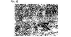
- FIG. 12 is a micrograph of whiskers in the example.
- the present inventor has conducted various studies on the relationship between a threaded joint for pipes, seizure resistance, and high torque performance, using a pipe screw having a shoulder. As a result, the following findings were obtained.
- FIG. 1 is a diagram showing a relationship between a rotational speed and a torque of a steel pipe when a pipe threaded joint having a shoulder portion is screwed.
- FIG. 1 is also called a torque chart.
- the torque increases in proportion to the rotation speed. At this time, the rate of increase in torque is low. If the screws are further tightened, the shoulders will come into contact with each other. The torque at this time is called shouldering torque. If the screwing is further tightened after reaching the shouldering torque, the torque rises again in proportion to the rotation speed.
- the rate of increase in torque at this time is higher than that before reaching the shouldering torque.
- torque reaches a predetermined value (fastening torque)
- screw tightening is completed. If the torque for tightening the screws reaches the tightening torque, the metal seal portions interfere with each other with an appropriate surface pressure. In this case, the airtightness of the pipe threaded joint is increased.
- the torque on-shoulder resistance ⁇ T′ which is the difference between the shouldering torque and the yield torque, is large, there is a margin in the fastening torque range. As a result, the tightening torque can be easily adjusted. Therefore, it is preferable that the torque on-shoulder resistance ⁇ T′ is large.
- excellent high torque performance means that the torque-on-shoulder resistance ⁇ T′ is large when the pipe threaded joint has a shoulder portion.
- the present inventor In order to obtain excellent high torque performance, it is effective to reduce the shouldering torque or increase the yield torque when the pipe threaded joint has a shoulder portion.
- the present inventor has focused on a method of increasing the yield torque.
- the present inventor considered that the inclusion of hard particles in the solid lubricating coating would increase the yield torque at high surface pressure, and as a result, enhance the high torque performance.
- PTFE polytetrafluoroethylene
- FIG. 2 is a diagram showing the relationship between the glass frit content in the solid lubricating coating and the torque on shoulder resistance ⁇ T′.
- FIG. 2 was obtained by the example described below.
- the torque-on-shoulder resistance ⁇ T′ was obtained by using the numerical value of the torque-on-shoulder resistance ⁇ T′ when API standard dope was used instead of the solid lubricating coating in Test No. 9 in Examples described later as a reference (100). Further, it is a relative value of the torque on-shoulder resistance ⁇ T′ in the present embodiment.
- the white circles ( ⁇ ) in FIG. 2 indicate the torque-on-shoulder resistance ⁇ T′ of the example in which the solid lubricating coating is formed.
- the triangle mark ( ⁇ ) in FIG. 2 indicates the torque on-shoulder resistance ⁇ T′ when the API standard dope is used instead of the solid lubricating coating.
- the solid lubricating coating contains glass frit, it is not clear why excellent high torque performance can be obtained.
- the contact pressure between the contact surfaces becomes high (high contact pressure).
- the glass frit is present on the contact surface at the time of high surface pressure and in the powder generated by the wear of the solid lubricating coating and the threaded joint for pipes. Glass frits increase the coefficient of friction between contacting surfaces. As a result, high torque is maintained at high surface pressure, and excellent high torque performance is obtained.
- the glass frit exhibits excellent high torque performance by increasing the friction coefficient at high surface pressure. Therefore, even when the pipe threaded joint having no shoulder is used, the glass frit exhibits excellent high torque performance in the final stage of screw tightening.
- the present inventor has further found that not only excellent high torque performance but also excellent seizure resistance can be obtained by adjusting the content of the glass frit in the solid lubricating coating.
- FIG. 3 is a diagram showing the relationship between the glass frit content in the solid lubricating coating and seizure resistance.
- FIG. 3 was obtained by the example described below.
- the vertical axis represents the number of times (times) the fastening could be performed without burning.
- the number of times that it can be fastened without burning is 8 or more. That is, when the glass frit content is 10.0 mass% or less, excellent seizure resistance is obtained in addition to excellent high torque performance.
- the above-mentioned solid lubricating coating contains 0.01 to 10.0% by mass of glass frit.
- the pipe threaded joint has excellent seizure resistance in addition to excellent high torque performance.
- the method for manufacturing a threaded joint for pipes includes a preparation step and a solid lubricant film forming step.
- a pin, a box, and a composition for forming a solid lubricating coating are prepared.
- the pin has a pin side contact surface that includes a pin side thread.
- the box has a box-side contact surface that includes box-side threads.
- the composition for forming a solid lubricating coating contains a binder, a lubricant and a glass frit.
- the solid lubricating coating forming composition is applied to at least one of the pin-side contact surface and the box-side contact surface and then solidified to form a solid lubricating coating.
- a solid lubricating coating is manufactured using a composition for forming a solid lubricating coating containing glass frit. Therefore, a pipe threaded joint having excellent high torque performance can be obtained.
- the pin further includes a pin side metal seal and a pin side shoulder portion
- the box further includes a box side metal seal portion and a box side shoulder portion.
- FIG. 6 is a sectional view of a pipe threaded joint.
- the pin 3 includes a pin side screw portion 31, a pin side metal seal portion 32, and a pin side shoulder portion 33.
- the box 4 includes a box-side screw portion 41, a box-side metal seal portion 42, and a box-side shoulder portion 43.
- the portions that come into contact when the pin 3 and the box 4 are screwed are referred to as contact surfaces 34 and 44.
- the screw parts pin side screw part 31 and box side screw part 41
- metal seal parts pin side metal seal part 32 and box side metal seal part). 42
- the shoulder portions the pin side shoulder portion 33 and the box side shoulder portion 43
- the pin side shoulder portion 33, the pin side metal seal portion 32, and the pin side screw portion 31 are arranged in this order from the end of the steel pipe 1.
- the box-side screw portion 41, the box-side metal seal portion 42, and the box-side shoulder portion 43 are arranged in this order from the end of the steel pipe 1 or the coupling 2.
- the arrangement of the pin-side screw portion 31 and the box-side screw portion 41, the pin-side metal seal portion 32 and the box-side metal seal portion 42, and the pin-side shoulder portion 33 and the box-side shoulder portion 43 is limited to the arrangement of FIG. 6. Instead, it can be changed as appropriate. For example, as shown in FIG.
- the pin side screw part 31 in the pin 3, from the end of the steel pipe 1, the pin side screw part 31, the pin side metal seal part 32, the pin side shoulder part 33, the pin side metal seal part 32 and the pin side screw part. They may be arranged in the order of 31.
- the box-side screw portion 41, the box-side metal seal portion 42, the box-side shoulder portion 43, the box-side metal seal portion 42, and the box-side screw portion 41 are arranged in this order from the end of the steel pipe 1 or the coupling 2. May be.
- a so-called premium joint including a metal seal portion (pin side metal seal portion 32 and box side metal seal portion 42) and a shoulder portion (pin side shoulder portion 33 and box side shoulder portion 43) is shown. ..
- the metal seal portion (pin side metal seal portion 32 and box side metal seal portion 42) and shoulder portion (pin side shoulder portion 33 and box side shoulder portion 43) may be omitted.
- the solid lubricating coating of the present embodiment can be suitably applied to a pipe threaded joint having no metal seal portion and shoulder portion. Without the metal seal and shoulder, the pin-side contact surface 34 includes the pin-side threaded portion 31. Without the metal seal and shoulder, the box-side contact surface 44 includes the box-side threaded portion 41.
- the pipe threaded joint comprises a solid lubricating coating on at least one of the pin side contact surface 34 and the box side contact surface 44.
- FIG. 7 is a cross-sectional view of the pipe threaded joint according to the present embodiment.
- the solid lubricating coating 21 is formed by applying a composition for forming a solid lubricating coating to at least one of the pin-side contact surface 34 and the box-side contact surface 44 and then solidifying the composition, as in the production method described later.
- the solid lubricating coating 21 contains a binder, a lubricant and a glass frit. Therefore, the composition for forming the solid lubricating coating 21 also contains the binder, the lubricant and the glass frit.
- the composition may be a solvent-free composition or a solvent-type composition dissolved in a solvent.
- the mass% of each component means the mass% when the total mass of all components other than the solvent contained in the composition is 100%. That is, the content of each component in the composition and the content of each component in the solid lubricating coating 21 are the same.
- the composition for forming the solid lubricating coating 21 is also simply referred to as “composition”.
- the organic resin is, for example, one or two selected from the group consisting of thermosetting resins and thermoplastic resins.
- the thermosetting resin is, for example, epoxy resin, phenol resin, furan resin, polyimide resin, melamine resin, urea resin, silicone resin, polyurethane resin (thermosetting), unsaturated polyester resin, casein resin, alkyd resin, diallyl phthalate resin. And one or more selected from the group consisting of polyamino bismaleimide resin.
- thermoplastic ionomer resin, acrylonitrile/butadiene/styrene resin, acrylonitrile/styrene resin, polyvinyl alcohol resin, polyvinyl butyral resin, polyvinylidene chloride resin, polyethylene terephthalate resin, polyacetal resin, polycarbonate resin, polyphenylene ether resin, polybutylene terephthalate
- the binder is one or more selected from the group consisting of epoxy resin, phenol resin, furan resin, polyamideimide resin, polyamide resin, polyimide resin, urethane resin and polyetheretherketone resin.
- epoxy resin phenol resin, furan resin, polyamideimide resin, polyamide resin, polyimide resin, urethane resin and polyetheretherketone resin.
- organic resins have appropriate hardness. Therefore, the wear resistance, seizure resistance, and high torque performance of the solid lubricating coating 21 are further enhanced.
- the binder is one or more selected from the group consisting of epoxy resin, phenol resin, furan resin, polyamide-imide resin and polyamide resin.
- the binder is one or more selected from the group consisting of epoxy resin, polyamide-imide resin and polyamide resin.
- the content of the binder in the solid lubricating coating 21 is preferably 50 to 90% by mass.
- the content of the binder is 60% by mass or more, the adhesion of the solid lubricating coating 21 to the contact surface 34 or 44 of the pipe threaded joint is further enhanced. Therefore, the lower limit of the content of the binder in the solid lubricating coating 21 is more preferably 60% by mass.
- the glass frit refers to glass particles.
- the shape of the glass frit is not fibrous but granular, lumpy and spherical.
- the glass frit is generally used mainly in various fields of electronics, such as sealing (sealing, adhesion) of a display panel and various electronic components, coating (protective film), and insulating film.
- sealing sealing, adhesion
- coating protecting film
- insulating film insulating film
- the glass frit a commercially available glass frit can be used.
- the glass frit is, for example, one or two kinds such as (trade name) ASF-1560 and (trade name) ASF-1561 manufactured by Asahi Glass Co., Ltd., and (trade name) VY0144 and (trade name) EY0077 manufactured by Nippon Frit Co., Ltd. The above can be mixed and used.
- the major axis of the glass frit is calculated by the following method. First, a part of the solid lubricating coating 21 is sampled. The solid lubricating coating 21 is burned at 600° C., and the burning residue is collected. The glass frit is recovered from the residue by the difference in specific gravity. The obtained glass frit is analyzed according to the dynamic image analysis method specified in JIS Z8827-1 (2008) and JIS Z8827-1-2 (2010). From the analysis result, the arithmetic average of the maximum Feret diameters of the respective particles of the glass frit within the same visual field is calculated, and the major axis ( ⁇ m) is calculated.
- the glass frit has an aspect ratio of 10 or less.
- the aspect ratio of the glass frit is a value defined by JIS Z8827-1 (2008), which is obtained by dividing the maximum Feret diameter of each particle by the minimum Feret diameter of each particle.
- the aspect ratio of the glass frit is more preferably less than 10, still more preferably 5 or less, and most preferably 3 or less.
- the aspect ratio of the glass frit is calculated by the following method. First, a part of the solid lubricating coating 21 is sampled. The solid lubricating coating 21 is burned at 600° C., and the burning residue is collected. The glass frit is recovered from the residue by the difference in specific gravity. The obtained glass frit is analyzed according to the dynamic image analysis method specified in JIS Z8827-1 (2008) and JIS Z8827-1-2 (2010). From the analysis result, the arithmetic mean of the maximum Feret diameters of the respective particles of the glass frit within the same visual field is calculated. From the analysis result, the arithmetic average of the minimum Feret diameters of the respective particles of the glass frit within the same visual field is calculated. The arithmetic mean of the largest Feret diameter is divided by the arithmetic mean of the smallest Feret diameter. This is the aspect ratio of the glass frit.
- the lower limit of the content of the glass frit in the solid lubricating coating 21 is, for example, 0.001% by mass.
- the content of the glass frit is preferably 0.01% by mass or more.
- the lower limit of the content of the glass frit is more preferably 0.5% by mass, further preferably 1.0% by mass.
- the chemical composition of the glass frit can be adjusted appropriately.
- the glass frit is, for example, in mass %, SiO 2 : 40 to 70%, Al 2 O 3 : 1 to 20%, CaO: 0.1 to 25%, B 2 O 3 : 0 to 40%, MgO: 0 to 3%, Na 2 O: 0 to 15%, K 2 O: 0 to 10%, and ZnO: 0 to 10% may be contained.
- the solid lubricating coating 21 may also contain other known rust preventive additives, preservatives and the like.
- the solid lubricating coating 21 needs to have rust-preventive properties for a long period of time before being actually used. Therefore, the solid lubricating coating 21 may contain a rust preventive additive.
- the anticorrosive additive is a general term for additives having corrosion resistance.
- the rust preventive additive is, for example, one or more selected from the group consisting of aluminum tripolyphosphate, aluminum phosphite and calcium ion exchange silica.
- the antirust additive contains one or two selected from the group consisting of calcium ion exchange silica and aluminum phosphite.
- As the rust preventive additive a commercially available reaction water repellent agent or the like can also be used.
- the total content of other components (corrosion preventive additives, preservatives, etc.) in the solid lubricating coating 21 is 10% by mass or less.
- the total content of other components is 10% by mass or less, the lubricity of the solid lubricating coating 21 is stably enhanced.
- the thickness of the solid lubricating coating 21 is measured by the following method.
- the thickness of the solid lubricating coating 21 is measured at four points on the contact surface 34 or 44 on which the solid lubricating coating 21 is formed, using an eddy current phase type film thickness meter PHASCOPE PMP910 manufactured by Helmut Fischer GmbH.
- the measurement is performed by a method according to ISO (International Organization for Standardization) 21968 (2005).
- the measurement points are four points (four points of 0°, 90°, 180°, 270°) in the pipe circumferential direction of the pipe threaded joint.
- the arithmetic average of the measurement results is the thickness of the solid lubricating coating 21.
- the solid lubricating coating 21 may be disposed on the entire surface of at least one of the pin-side contact surface 34 and the box-side contact surface 44, or may be disposed only on a part thereof.
- the pipe threaded joint has a metal seal portion (pin side metal seal portion 32 and box side metal seal portion 42) and a shoulder portion (pin side shoulder portion 33 and box side shoulder portion 43)
- the metal seal portions 32 and 42 are provided with a pin side contact surface 34 having a metal seal portion (pin side metal seal portion 32 and box side metal seal portion 42) and a shoulder portion (pin side shoulder portion 33 and box side shoulder portion 43).
- the box side contact surfaces 44 When partially arranged on at least one of the box side contact surfaces 44, it is arranged at at least one of the pin side metal seal portion 32, the box side metal seal portion 42, the pin side shoulder portion 33 and the box side shoulder portion 43. May be. On the other hand, if the solid lubricating coating 21 is arranged on at least one of the pin side contact surface 34 and the box side contact surface 44, the production efficiency of the threaded joint for pipes is increased.
- the solid lubricating coating 21 may be a single layer or multiple layers.
- the multi-layer means a state in which the solid lubricating coating 21 is laminated in two or more layers from the contact surface 34 or 44 side. By repeating the application and solidification of the composition, two or more solid lubricating coatings 21 can be formed.
- the solid lubricating coating 21 may be directly arranged on at least one of the pin-side contact surface 34 and the box-side contact surface 44, or may be arranged after being subjected to a base treatment described later.
- the composition of the base material of the threaded joint for pipes is not particularly limited.
- the base material is, for example, carbon steel, stainless steel, alloy steel or the like.
- alloy steels duplex stainless steels containing alloy elements such as Cr, Ni and Mo and high alloy steels such as Ni alloys have high corrosion resistance. Therefore, when these high alloy steels are used as the base material, excellent corrosion resistance can be obtained in a corrosive environment containing hydrogen sulfide, carbon dioxide and the like.
- the pin 3 has a pin-side contact surface 34 including a pin-side threaded portion 31, as described above.
- the pin 3 may have the pin-side contact surface 34 including the pin-side screw portion 31, the pin-side metal seal portion 32, and the pin-side shoulder portion 33, as described above.
- the box 4 has a box-side contact surface 44 including a box-side threaded portion 41, as described above.
- the box 4 may have a box-side contact surface 44 including a box-side threaded portion 41, a box-side metal seal portion 42, and a box-side shoulder portion 43, as described above.
- the solvent type composition can be produced, for example, by dissolving or dispersing a binder, a lubricant and a glass frit in a solvent and mixing them.
- the solvent is, for example, one or two selected from the group consisting of water and an organic solvent.
- the ratio of the solvent is not particularly limited. The proportion of the solvent may be adjusted to an appropriate viscosity according to the coating method. The ratio of the solvent is, for example, 30 to 50% by mass based on 100% by mass of all components other than the solvent.
- the solid lubricant film forming step includes a coating step and a solidifying step.
- the coating step the solid lubricating coating forming composition is coated on at least one of the pin-side contact surface 34 and the box-side contact surface 44.
- the solidifying step the solid lubricating coating forming composition applied on at least one of the pin-side contact surface 34 and the box-side contact surface 44 is solidified to form the solid lubricating coating 21.
- the composition can be applied using the hot melt method.
- the hot melt method the composition is heated to melt the resin and bring it into a low-viscosity fluid state. It is carried out by spraying the composition in a fluid state from a spray gun having a temperature maintaining function.
- the composition is heated and melted in a tank equipped with a suitable stirring device, and is supplied to a spray head (maintained at a predetermined temperature) of a spray gun through a metering pump by a compressor to be sprayed.
- the holding temperature in the tank and in the spraying head is adjusted according to the melting point of the resin in the composition.
- the coating method may be brush coating, dipping or the like instead of spray coating.
- the composition in a solution state is applied to at least one of the pin side contact surface 34 and the box side contact surface 44 by spray coating or the like.
- the viscosity of the composition is adjusted so that the composition can be spray-applied at room temperature and atmospheric pressure.
- the solid lubricant film 21 is formed by solidifying the composition applied to at least one of the pin side contact surface 34 and the box side contact surface 44.
- the composition in a molten state solidifies to solid lubricant coating 21. Is formed.
- a known cooling method can be used.
- the cooling method is, for example, air cooling or air cooling.
- the solidification process may be performed by rapid cooling such as a nitrogen gas and carbon dioxide cooling system.
- rapid cooling such as a nitrogen gas and carbon dioxide cooling system.
- rapid cooling it is indirectly cooled from the opposite surface of the contact surface 34 or 44 (the outer surface of the steel pipe 1 or the coupling 2 in the case of the box 4, the inner surface of the steel pipe 1 in the case of the pin 3).
- rapid cooling it is indirectly cooled from the opposite surface of the contact surface 34 or 44 (the outer surface of the steel pipe 1 or the coupling 2 in the case of the box 4, the inner surface of the steel pipe 1 in the case of the pin 3).
- the arithmetic mean roughness Ra and the maximum height roughness Rz referred to in this specification are measured based on JIS B 0601 (2001). Measurement is performed using a scanning probe microscope SPI3800N manufactured by SII Nano Technology. The measurement condition is a region of 2 ⁇ m ⁇ 2 ⁇ m of the sample as a unit of the number of acquired data, and the number of acquired data is 1024 ⁇ 1024. The standard length is 2.5 mm.
- the pickling treatment is a treatment for roughening the contact surface 34 or 44 by immersing at least one of the pin-side contact surface 34 and the box-side contact surface 44 in a strong acid solution such as sulfuric acid, hydrochloric acid, nitric acid or hydrofluoric acid. This can increase the surface roughness of the contact surface 34 or 44.
- the chemical conversion treatment is a treatment for forming a porous chemical conversion film having a large surface roughness.
- the chemical conversion treatment is, for example, a phosphate chemical conversion treatment, an oxalate chemical conversion treatment, and a borate chemical conversion treatment. From the viewpoint of the adhesion of the solid lubricating coating 21, the phosphate chemical conversion treatment is preferable.
- the phosphate chemical conversion treatment is, for example, a phosphate chemical conversion treatment using manganese phosphate, zinc phosphate, iron manganese phosphate or zinc calcium phosphate.
- the surface may be adjusted before the phosphate chemical conversion treatment.
- Surface conditioning is a treatment of immersing in a surface conditioning aqueous solution containing colloidal titanium. After the phosphate conversion treatment, it is preferable to wash with water or hot water and then dry.
- the chemical conversion coating is porous. Therefore, if the solid lubricating coating 21 is formed on the chemical conversion coating, the adhesion of the solid lubricating coating 21 is further enhanced by the so-called “anchor effect".
- the preferred thickness of the phosphate coating is 5-40 ⁇ m. If the thickness of the phosphate coating is 5 ⁇ m or more, sufficient corrosion resistance can be secured. When the thickness of the phosphate coating is 40 ⁇ m or less, the adhesiveness of the solid lubricating coating 21 is stably enhanced.
- the thickness of the phosphate coating is calculated by the following method.
- the threaded pipe joint with the phosphate coating is cut in the thickness direction of the phosphate coating (perpendicular to the axial direction of the thread joint for the pipe).
- the cross section of the phosphate coating is observed with an optical microscope at a magnification of 500 times to measure the thickness of the phosphate coating.
- the cutting is performed again by cutting again.
- the threaded joint for pipes is cut in a direction inclined by 60° from the direction perpendicular to the axial direction of the threaded joint for pipes.
- the cross section of the obtained phosphate coating is observed with an optical microscope at a magnification of 500 times to measure the thickness of the phosphate coating.
- the thickness measured again is the thickness of the phosphate coating.
- a Zn alloy plating layer is formed by electroplating on the surface roughness formed on at least one of the pin side contact surface 34 and the box side contact surface 44.
- the Zn alloy plating layer forming step includes, for example, a single layer plating process using Cu, Sn or Ni metal, a single layer plating process using a Cu—Sn alloy, a two layer plating process including a Cu layer and a Sn layer, and a Ni layer and Cu. It is a three-layer plating process using a layer and a Sn layer.
- a single layer plating process using Cu, Sn or Ni metal a single layer plating process using a Cu—Sn alloy
- a two layer plating process including a Cu layer and a Sn layer and a Ni layer and Cu. It is a three-layer plating process using a layer and a Sn layer.
- Cu-Sn alloy plating treatment, Cu plating-Sn plating two-layer plating treatment, and Ni plating-Cu plating-Sn plating three-layer plating Treatment is preferred.
- the plating bath when forming a Cu—Sn—Zn alloy plating layer, contains copper ions, tin ions and zinc ions.
- the composition of the plating bath is preferably Cu: 1 to 50 g/L, Sn: 1 to 50 g/L and Zn: 1 to 50 g/L.
- the electroplating conditions are, for example, a plating bath pH: 1 to 10, a plating bath temperature: 60° C., a current density: 1 to 100 A/dm 2, and a treatment time: 0.1 to 30 minutes.
- the plating bath When forming a Zn—Ni alloy plating layer, the plating bath contains zinc ions and nickel ions.
- the composition of the plating bath is preferably Zn: 1 to 100 g/L and Ni: 1 to 50 g/L.
- the electroplating conditions are, for example, a plating bath pH: 1 to 10, a plating bath temperature: 60° C., a current density: 1 to 100 A/dm 2, and a treatment time: 0.1 to 30 minutes.
- the hardness of the Zn alloy plating layer is preferably 300 or more in micro Vickers. When the hardness of the Zn alloy plating layer is 300 or more, the corrosion resistance of the threaded joint for pipes is more stably enhanced.
- the hardness of the Zn alloy plating layer is measured as follows. In the Zn alloy plating layer of the obtained threaded joint for pipes, five arbitrary regions are selected. In each selected area, the Vickers hardness (HV) is measured according to JIS Z2244 (2009). The test conditions are, for example, a test temperature of room temperature (25° C.) and a test force of 2.94 N (300 gf). The average of the obtained values (5 in total) is defined as the hardness of the Zn alloy plating layer.
- the thickness of the lowermost plating layer be less than 1 ⁇ m.
- the thickness of the plating layer is preferably 5 to 15 ⁇ m.
- Measure the thickness of the Zn alloy plating layer as follows. A probe of an overcurrent phase type film thickness meter conforming to ISO (International Organization for Standardization) 21968 (2005) is brought into contact with the contact surface 34 or 44 on which the Zn alloy plating layer is formed. The phase difference between the high frequency magnetic field on the input side of the probe and the overcurrent excited by it on the Zn—Ni alloy plating is measured. This phase difference is converted into the thickness of the Zn alloy plating layer.
- ISO International Organization for Standardization
- trivalent chromate treatment When the above-mentioned Zn alloy plating treatment is carried out, trivalent chromate treatment may be carried out after the Zn alloy plating treatment.
- the trivalent chromate treatment is a treatment for forming a chromate film of trivalent chromium.
- the coating film formed by the trivalent chromate treatment suppresses white rust on the surface of the Zn alloy plating layer. This improves the product appearance.
- the white rust of the Zn alloy plating layer is not the rust of the pipe thread joint base material. Therefore, it does not affect the seizure resistance and corrosion resistance of the thread joint for pipe.
- the solid lubricating film 21 on the trivalent chromate film By forming, the adhesiveness of the solid lubricating coating 21 is further enhanced.
- the trivalent chromate treatment can be performed by a known method. For example, at least one of the pin-side contact surface 34 and the box-side contact surface 44 is dipped in the chromate treatment liquid or the chromate treatment liquid is sprayed on at least one of the pin-side contact surface 34 and the box-side contact surface 44. Then, the contact surface is washed with water. Alternatively, the contact surface 34 or 44 is dipped in a chromate treatment liquid, and after being energized, washed with water. Alternatively, the chromate treatment liquid is applied to the contact surface 34 or 44 and dried by heating. The treatment conditions of trivalent chromate can be set appropriately. The thickness of the trivalent chromate coating can be measured by the same method as the solid lubricating coating 21.
- the above-mentioned base treatments may be carried out for only one type, but a plurality of base treatments may be combined.
- one kind of undercoating it is preferable to carry out at least one kind of undercoating selected from the group consisting of sandblasting, pickling, phosphate chemical conversion and Zn alloy plating.
- Two or more types of base treatment may be implemented.
- the phosphate chemical conversion treatment is carried out after the sandblast treatment.
- a Zn alloy plating treatment is performed after the sandblast treatment.
- the zinc alloy plating treatment is performed after the sandblast treatment, and the trivalent chromate treatment is further performed.
- the solid lubricating coating 21 is formed. Thereby, the adhesion and corrosion resistance of the solid lubricating coating 21 can be further improved.
- the present disclosure is not limited to the embodiments.
- the contact surface of the pin is called the pin surface and the contact surface of the box is called the box surface.
- % in the examples is% by mass unless otherwise specified.
- seizure resistance peerated fastening test
- high torque performance were evaluated using a real pipe (length of about 12 m).
- the repeated fastening test was performed with a fastening torque of 28450 Nm. Fastening was carried out until irreversible seizure of the threaded portion or seizure of the metal seal portion occurred. The number of times that screw tightening and screw returning could be repeated without seizure was judged to be acceptable when the number of times was 5 or more.
- screw joints VAM21 (registered trademark) for oil country tubular goods made by Nippon Steel Co., Ltd. (outer diameter: 244.48 mm (9 inches 5 minutes), wall thickness: 11.99 mm (0.472 inches)), steel grade Is carbon steel (C: 0.25%, Si: 0.22%, Mn: 0.7%, P: 0.02%, S: 0.01%, Cu: 0.04%, Ni: 0. 05%, Cr: 0.95%, Mo: 0.15%, balance: iron and impurities).
- the surface treatment (appropriate) shown in Table 1 and the solid lubricating coating or the other lubricating coating formed by the composition for forming a solid lubricating coating according to the present embodiment are formed on the pin surface and the box surface of each test number, and each test is performed. Numbered pins and boxes were prepared.
- Blasting was performed on the pin surface and the box surface of each test number with the test numbers as shown in Table 1.
- the blasting was performed by sandblasting (abrasive grain Mesh100) to form a surface roughness.
- the arithmetic mean roughness Ra and the maximum height roughness Rz of each test number were as shown in Table 1.
- the arithmetic average roughness Ra and the maximum height roughness Rz were measured based on JIS-B0601 (2001).
- a scanning probe microscope SPI3800N manufactured by SII Nano Technology was used to measure the arithmetic average roughness Ra and the maximum height roughness Rz.
- the measurement conditions were a region of 2 ⁇ m ⁇ 2 ⁇ m of the sample as a unit of the number of acquired data, and the number of acquired data was 1024 ⁇ 1024.
- a Zn-Ni alloy plating layer, a Cu-Sn-Zn alloy plating layer, and a solid lubricating coating shown in Table 1 were formed to prepare pins and boxes for each test number.
- Table 1 only the main components are described in the column of "solid lubricating coating”.
- the detailed composition of the solid lubricating coating was as follows.
- "thickness" in the column of "solid lubricating coating” describes the thickness of the obtained solid lubricating coating.
- the method for measuring the thickness of the solid lubricating coating was as described above.
- each Zn-Ni alloy plating layer, Cu-Sn-Zn alloy plating layer, and solid lubricating coating was as follows.
- the thicknesses of the alloy plating layer and other coating layers were as shown in Table 1.
- the method for measuring the thickness of each layer was as described above.
- Test number 1 In test number 1, mechanical grinding finish was performed on the pin and box surfaces.
- the composition for forming a solid lubricating coating was applied thereon.
- the composition for forming a solid lubricating coating contained an epoxy resin (the balance), PTFE particles (20%), glass frit A (0.8%), and a solvent (water, alcohol, surfactant).
- the composition for forming a solid lubricating coating was applied by spraying, and then dried by heating at 90° C. for 5 minutes. After heating and drying, solidification treatment was performed at 210° C. for 20 minutes to form a solid lubricating coating.
- Test number 2 mechanical grinding finish was performed on the pin and box surfaces.
- the composition for forming a solid lubricating coating was applied thereon.
- the composition for forming a solid lubricating coating contained an epoxy resin (the balance), PTFE particles (10%), glass frit B (2.0%), and a solvent (water, alcohol, surfactant).
- the composition for forming a solid lubricating coating was applied by spraying, and then dried by heating at 90° C. for 5 minutes. After heating and drying, solidification treatment was performed at 210° C. for 20 minutes to form a solid lubricating coating.
- Test number 3 surface roughness was formed on the pin surface by blasting.
- Zn—Ni alloy plating was performed by electroplating on the pin surface having surface roughness to form a Zn—Ni alloy plating layer.
- the Zn-Ni alloy plating bath used was Dainjin Alloy N-PL manufactured by Daiwa Kasei Co., Ltd.
- the electroplating conditions were: plating bath pH: 6.5, plating bath temperature: 25° C., current density: 2 A/dm 2 , and treatment time: 18 minutes.
- the composition of the Zn—Ni alloy plating layer was Zn:85% and Ni:15%.
- a trivalent chromate treatment was performed on the obtained Zn—Ni alloy plated layer to form a film.
- the trivalent chromate treatment liquid Dyne Chromate TR-02 manufactured by Daiwa Kasei Co., Ltd. was used.
- the trivalent chromate treatment conditions were: bath pH: 4.0, bath temperature: 25° C., and treatment time: 50 seconds.
- Test number 4 surface roughness was formed on the pin surface by blasting.
- Zn—Ni alloy plating was performed by electroplating on the pin surface having surface roughness to form a Zn—Ni alloy plating layer.
- the Zn-Ni alloy plating bath used was Dainjin Alloy N-PL manufactured by Daiwa Kasei Co., Ltd.
- the electroplating conditions were: plating bath pH: 6.5, plating bath temperature: 25° C., current density: 2 A/dm 2 , and treatment time: 18 minutes.
- the composition of the Zn—Ni alloy plating layer was Zn:85% and Ni:15%.
- a trivalent chromate treatment was performed on the obtained Zn—Ni alloy plated layer to form a film.
- the trivalent chromate treatment liquid Dyne Chromate TR-02 manufactured by Daiwa Kasei Co., Ltd. was used.
- the trivalent chromate treatment conditions were: bath pH: 4.0, bath temperature: 25° C., and treatment time: 50 seconds.
- the composition for forming a solid lubricating coating contained a polyamideimide resin (the balance), fluorinated graphite particles (10%), glass frit D (8.0%), and a solvent (water, alcohol, surfactant).
- the composition for forming a solid lubricating coating was applied by spraying, and then dried by heating at 90° C. for 5 minutes. After drying by heating, solidification treatment was performed at 230° C. for 20 minutes to form a solid lubricating coating.
- Test number 5 In test number 5, the pin surface was subjected to mechanical grinding finish. Zn-Ni alloy plating was performed thereon by electroplating to form a Zn-Ni alloy plating layer.
- the Zn-Ni alloy plating bath used was Dainjin Alloy N-PL manufactured by Daiwa Kasei Co., Ltd.
- the electroplating conditions were: plating bath pH: 6.5, plating bath temperature: 25° C., current density: 2 A/dm 2 , and treatment time: 18 minutes.
- the composition of the Zn—Ni alloy plating layer was Zn:85% and Ni:15%. Further, a trivalent chromate treatment was performed on the obtained Zn—Ni alloy plated layer to form a film.
- Zn-Ni alloy plating was performed by electroplating on the surface of the box having surface roughness to form a Zn-Ni alloy plating layer.
- the Zn-Ni alloy plating bath used was Dainjin Alloy N-PL manufactured by Daiwa Kasei Co., Ltd.
- the electroplating conditions were: plating bath pH: 6.5, plating bath temperature: 25° C., current density: 2 A/dm 2 , and treatment time: 18 minutes.
- the composition of the Zn—Ni alloy plating layer was Zn:85% and Ni:15%. Further, the composition for forming a solid lubricating coating was applied on the obtained Zn-Ni alloy plated layer.
- the composition for forming a solid lubricating coating contained a phenol resin (the balance), PTFE particles (15%), glass frit A (10.0%), and a solvent (water, alcohol, surfactant).
- the composition for forming a solid lubricating coating was applied by spraying, and then dried by heating at 90° C. for 5 minutes. After drying by heating, solidification treatment was performed at 230° C. for 20 minutes to form a solid lubricating coating.
- the trivalent chromate treatment liquid Dyne Chromate TR-02 manufactured by Daiwa Kasei Co., Ltd. was used.
- the trivalent chromate treatment conditions were: bath pH: 4.0, bath temperature: 25° C., and treatment time: 50 seconds.
- Cu-Sn-Zn alloy plating was carried out by electroplating on the surface of the box having a surface roughness to form a Cu-Sn-Zn alloy plating layer.
- As the Cu-Sn-Zn alloy plating bath a plating bath manufactured by Nippon Kagaku Sangyo Co., Ltd. was used.
- the Cu-Sn-Zn alloy plating layer was formed by electroplating.
- the electroplating conditions were: plating bath pH: 14, plating bath temperature: 45° C., current density: 2 A/dm 2, and treatment time: 40 minutes.
- the composition of the Cu—Sn—Zn alloy plated layer was Cu: 60%, Sn: 30%, Zn: 10%.
- the composition for forming a solid lubricating coating was applied on the obtained Cu—Sn—Zn alloy plated layer.
- the composition for forming a solid lubricating coating contained a polyamide resin (the balance), graphite particles (5%), glass frit A (8.0%), and a solvent (water, alcohol, surfactant).
- the composition for forming a solid lubricating coating was applied by spraying, and then dried by heating at 90° C. for 5 minutes. After drying by heating, solidification treatment was performed at 230° C. for 20 minutes to form a solid lubricating coating.
- Test number 7 In test number 7, the pin surface was mechanically ground. Zn-Ni alloy plating was performed thereon by electroplating to form a Zn-Ni alloy plating layer.
- the Zn-Ni alloy plating bath used was Dainjin Alloy N-PL manufactured by Daiwa Kasei Co., Ltd.
- the electroplating conditions were: plating bath pH: 6.5, plating bath temperature: 25° C., current density: 2 A/dm 2 , and treatment time: 18 minutes.
- the composition of the Zn—Ni alloy plating layer was Zn:85% and Ni:15%. Further, a trivalent chromate treatment was performed on the obtained Zn—Ni alloy plated layer to form a film.
- the trivalent chromate treatment liquid Dyne Chromate TR-02 manufactured by Daiwa Kasei Co., Ltd. was used.
- the trivalent chromate treatment conditions were: bath pH: 4.0, bath temperature: 25° C., and treatment time: 50 seconds.
- the composition for forming a solid lubricating coating contained an epoxy resin (the balance), PTFE particles (10%), glass frit A (15.0%), and a solvent (water, alcohol, surfactant).
- the composition for forming a solid lubricating coating was applied by spraying, and then dried by heating at 90° C. for 5 minutes. After heating and drying, solidification treatment was performed at 210° C. for 20 minutes to form a solid lubricating coating.
- Test number 8 In test number 8, the pin surface was mechanically ground. Zn-Ni alloy plating was performed thereon by electroplating to form a Zn-Ni alloy plating layer.
- the Zn-Ni alloy plating bath used was Dainjin Alloy N-PL manufactured by Daiwa Kasei Co., Ltd.
- the electroplating conditions were: plating bath pH: 6.5, plating bath temperature: 25° C., current density: 2 A/dm 2 , and treatment time: 18 minutes.
- the composition of the Zn—Ni alloy plating layer was Zn:85% and Ni:15%. Further, a trivalent chromate treatment was performed on the obtained Zn—Ni alloy plated layer to form a film.
- the trivalent chromate treatment liquid Dyne Chromate TR-02 manufactured by Daiwa Kasei Co., Ltd. was used.
- the trivalent chromate treatment conditions were: bath pH: 4.0, bath temperature: 25° C., and treatment time: 50 seconds.
- the surface roughness was formed on the box surface by blasting.
- Zn-Ni alloy plating was performed by electroplating on the surface of the box having surface roughness to form a Zn-Ni alloy plating layer.
- the electroplating conditions were the same as for the pin surface.
- the composition for forming a solid lubricating coating was applied onto the Zn-Ni alloy plating layer.
- the composition for forming a solid lubricating coating contained an epoxy resin (the balance), PTFE particles (10%), and a solvent (water, alcohol, surfactant).
- the composition for forming a solid lubricating coating was applied by spraying, and then dried by heating at 90° C. for 5 minutes. After heating and drying, solidification treatment was performed at 210° C. for 20 minutes to form a solid lubricating coating.
- the trivalent chromate treatment liquid Dyne Chromate TR-02 manufactured by Daiwa Kasei Co., Ltd. was used.
- the trivalent chromate treatment conditions were: bath pH: 4.0, bath temperature: 25° C., and treatment time: 50 seconds.
- the surface roughness was formed on the box surface by blasting.
- Zn-Ni alloy plating was performed by electroplating on the surface of the box having surface roughness to form a Zn-Ni alloy plating layer.
- the electroplating conditions were the same as for the pin surface.
- the composition for forming a solid lubricating coating was applied onto the Zn-Ni alloy plating layer.
- the composition for forming a solid lubricating coating is phenol resin (the balance), PTFE particles (15%), solvent (water, alcohol, surfactant), whisker (trade name) whisker manufactured by Maruo Calcium Co., Ltd. simulating glass fiber. It contained A (10%).
- the composition for forming a solid lubricating coating was applied by spraying, and then dried by heating at 90° C. for 5 minutes. After heating and drying, solidification treatment was performed at 210° C. for 20 minutes to form a solid lubricating coating.
- Ty yield torque
- the line segment L is used to define MTV.
- the difference between MTV and Ts was set as the torque on-shoulder resistance ⁇ T′ in this embodiment.
- the torque-on-shoulder resistance ⁇ T′ was obtained by using the numerical value of the torque-on-shoulder resistance ⁇ T′ when the API standard dope was used instead of the solid lubricating coating in Test No. 9 as a reference (100). It is a relative value of the shoulder resistance ⁇ T′. The results are shown in Table 3.
- the glass frit content of the solid lubricating coating was 0.01 to 10.0% by mass. Therefore, the seizure resistance was excellent as compared with Test No. 7 in which the glass frit content was 15.0% by mass.
- the pipe threaded joint of Test No. 8 had a solid lubricating coating on the box surface, but the solid lubricating coating did not contain glass frit. Therefore, excellent high torque performance could not be obtained.
- Test number 9 is a comparative example using a conventional compound grease.
Abstract
La présente invention concerne un raccord fileté pour tuyaux qui présente une excellente performance de couple et son procédé de production. Le raccord fileté de tuyau est pourvu d'une partie mâle (3), d'une partie femelle (4) et d'un film de lubrification solide (21). La parie mâle (3) présente une surface (34) de contact côté partie mâle qui comprend une partie filetée (31) côté partie mâle (31). La partie femelle (4) présente une surface (44) de contact côté partie femelle qui comprend une partie filetée (41) côté partie femelle. Le film de graisse solide (21) est disposé sur la surface de contact côté partie mâle (34) et/ou la surface de contact côté partie femelle (44). Le film de lubrification solide (21) comprend un liant, un lubrifiant et une fritte de verre.
Priority Applications (1)
| Application Number | Priority Date | Filing Date | Title |
|---|---|---|---|
| JP2020566433A JPWO2020149310A1 (ja) | 2019-01-16 | 2020-01-15 | 管用ねじ継手及び管用ねじ継手の製造方法 |
Applications Claiming Priority (2)
| Application Number | Priority Date | Filing Date | Title |
|---|---|---|---|
| JP2019-004852 | 2019-01-16 | ||
| JP2019004852 | 2019-01-16 |
Publications (1)
| Publication Number | Publication Date |
|---|---|
| WO2020149310A1 true WO2020149310A1 (fr) | 2020-07-23 |
Family
ID=71613921
Family Applications (1)
| Application Number | Title | Priority Date | Filing Date |
|---|---|---|---|
| PCT/JP2020/001097 WO2020149310A1 (fr) | 2019-01-16 | 2020-01-15 | Joint fileté pour tuyaux et procédé de production d'un joint fileté pour tuyaux |
Country Status (3)
| Country | Link |
|---|---|
| JP (1) | JPWO2020149310A1 (fr) |
| AR (1) | AR117811A1 (fr) |
| WO (1) | WO2020149310A1 (fr) |
Cited By (2)
| Publication number | Priority date | Publication date | Assignee | Title |
|---|---|---|---|---|
| WO2022230595A1 (fr) * | 2021-04-28 | 2022-11-03 | 日本製鉄株式会社 | Tuyau en acier pour puits de pétrole |
| WO2022255169A1 (fr) * | 2021-05-31 | 2022-12-08 | Jfeスチール株式会社 | Agent chimique, tuyau de puits de pétrole et joint à vis pour tuyau de puits de pétrole |
Citations (4)
| Publication number | Priority date | Publication date | Assignee | Title |
|---|---|---|---|---|
| JP2002257270A (ja) * | 2001-02-27 | 2002-09-11 | Sumitomo Metal Ind Ltd | 油井管用ネジ継手 |
| JP2002348587A (ja) * | 2001-05-24 | 2002-12-04 | Sumitomo Metal Ind Ltd | 鋼管用ねじ継手 |
| JP2013545946A (ja) * | 2010-11-10 | 2013-12-26 | ヴァルレック・マンネスマン・オイル・アンド・ガス・フランス | ねじ管状コンポーネントをコーティングするプロセス、ねじ管状コンポーネント及びもたらされる接続部 |
| WO2018216416A1 (fr) * | 2017-05-22 | 2018-11-29 | 新日鐵住金株式会社 | Joint fileté pour tuyau et procédé de fabrication d'un joint fileté pour tuyau |
-
2020
- 2020-01-13 AR ARP200100084A patent/AR117811A1/es unknown
- 2020-01-15 WO PCT/JP2020/001097 patent/WO2020149310A1/fr active Application Filing
- 2020-01-15 JP JP2020566433A patent/JPWO2020149310A1/ja active Pending
Patent Citations (4)
| Publication number | Priority date | Publication date | Assignee | Title |
|---|---|---|---|---|
| JP2002257270A (ja) * | 2001-02-27 | 2002-09-11 | Sumitomo Metal Ind Ltd | 油井管用ネジ継手 |
| JP2002348587A (ja) * | 2001-05-24 | 2002-12-04 | Sumitomo Metal Ind Ltd | 鋼管用ねじ継手 |
| JP2013545946A (ja) * | 2010-11-10 | 2013-12-26 | ヴァルレック・マンネスマン・オイル・アンド・ガス・フランス | ねじ管状コンポーネントをコーティングするプロセス、ねじ管状コンポーネント及びもたらされる接続部 |
| WO2018216416A1 (fr) * | 2017-05-22 | 2018-11-29 | 新日鐵住金株式会社 | Joint fileté pour tuyau et procédé de fabrication d'un joint fileté pour tuyau |
Cited By (3)
| Publication number | Priority date | Publication date | Assignee | Title |
|---|---|---|---|---|
| WO2022230595A1 (fr) * | 2021-04-28 | 2022-11-03 | 日本製鉄株式会社 | Tuyau en acier pour puits de pétrole |
| WO2022255169A1 (fr) * | 2021-05-31 | 2022-12-08 | Jfeスチール株式会社 | Agent chimique, tuyau de puits de pétrole et joint à vis pour tuyau de puits de pétrole |
| JP7193681B1 (ja) * | 2021-05-31 | 2022-12-20 | Jfeスチール株式会社 | 薬剤、油井管、及び油井管ねじ継手 |
Also Published As
| Publication number | Publication date |
|---|---|
| JPWO2020149310A1 (ja) | 2021-10-14 |
| AR117811A1 (es) | 2021-08-25 |
Similar Documents
| Publication | Publication Date | Title |
|---|---|---|
| JP6893978B2 (ja) | 管用ねじ継手及び管用ねじ継手の製造方法 | |
| CA2675613C (fr) | Joint a vis pour tuyau en acier | |
| AU2016374776B2 (en) | Threaded connection for pipe or tube and method for producing the threaded connection for pipe or tube | |
| US20040195825A1 (en) | Threaded joint for steel pipes | |
| JP6815498B2 (ja) | 管用ねじ継手及び管用ねじ継手の製造方法 | |
| WO2018003455A1 (fr) | Raccord à vis destiné à un tuyau et procédé de fabrication de raccord à vis destiné à un tuyau | |
| WO2020149310A1 (fr) | Joint fileté pour tuyaux et procédé de production d'un joint fileté pour tuyaux | |
| EP3696256B1 (fr) | Composition et joint fileté pour tuyaux pourvu d'une couche de film de revêtement lubrifiant qui est formée à partir de ladite composition | |
| WO2022039131A1 (fr) | Tuyau métallique pour puits de pétrole et procédé de fabrication d'un tuyau métallique pour puits de pétrole | |
| JP2018123349A (ja) | 管用ねじ継手及び管用ねじ継手の製造方法 | |
| JP2018123831A (ja) | 管用ねじ継手及び管用ねじ継手の製造方法 | |
| WO2020021691A1 (fr) | Raccord vissé pour tube et procédé de fabrication d'un raccord vissé pour tube | |
| WO2023063384A1 (fr) | Tuyau métallique pour puits de pétrole | |
| WO2023063385A1 (fr) | Tuyau métallique pour puits de pétrole | |
| OA19360A (en) | Threaded joint for pipe and method for producing threaded joint for pipe. | |
| EA045795B1 (ru) | Металлическая труба для нефтяной скважины и способ ее изготовления | |
| OA19598A (en) | Composition and threaded joint for pipes provided with lubricating coating film layer that is formed from said composition. |
Legal Events
| Date | Code | Title | Description |
|---|---|---|---|
| 121 | Ep: the epo has been informed by wipo that ep was designated in this application |
Ref document number: 20741883 Country of ref document: EP Kind code of ref document: A1 |
|
| ENP | Entry into the national phase |
Ref document number: 2020566433 Country of ref document: JP Kind code of ref document: A |
|
| NENP | Non-entry into the national phase |
Ref country code: DE |
|
| 122 | Ep: pct application non-entry in european phase |
Ref document number: 20741883 Country of ref document: EP Kind code of ref document: A1 |