WO2022039131A1 - Tuyau métallique pour puits de pétrole et procédé de fabrication d'un tuyau métallique pour puits de pétrole - Google Patents
Tuyau métallique pour puits de pétrole et procédé de fabrication d'un tuyau métallique pour puits de pétrole Download PDFInfo
- Publication number
- WO2022039131A1 WO2022039131A1 PCT/JP2021/029935 JP2021029935W WO2022039131A1 WO 2022039131 A1 WO2022039131 A1 WO 2022039131A1 JP 2021029935 W JP2021029935 W JP 2021029935W WO 2022039131 A1 WO2022039131 A1 WO 2022039131A1
- Authority
- WO
- WIPO (PCT)
- Prior art keywords
- contact surface
- resin
- box
- metal pipe
- pin
- Prior art date
Links
- 229910052751 metal Inorganic materials 0.000 title claims abstract description 316
- 239000002184 metal Substances 0.000 title claims abstract description 316
- 239000003129 oil well Substances 0.000 title claims abstract description 300
- 238000004519 manufacturing process Methods 0.000 title claims description 29
- 229920005989 resin Polymers 0.000 claims abstract description 399
- 239000011347 resin Substances 0.000 claims abstract description 399
- 239000007787 solid Substances 0.000 claims abstract description 50
- 239000000843 powder Substances 0.000 claims abstract description 42
- 238000000576 coating method Methods 0.000 claims description 165
- 238000007747 plating Methods 0.000 claims description 162
- 239000011248 coating agent Substances 0.000 claims description 150
- 239000000126 substance Substances 0.000 claims description 122
- VVOPUZNLRVJDJQ-UHFFFAOYSA-N phthalocyanine copper Chemical compound [Cu].C12=CC=CC=C2C(N=C2NC(C3=CC=CC=C32)=N2)=NC1=NC([C]1C=CC=CC1=1)=NC=1N=C1[C]3C=CC=CC3=C2N1 VVOPUZNLRVJDJQ-UHFFFAOYSA-N 0.000 claims description 88
- 239000000203 mixture Substances 0.000 claims description 84
- 238000011282 treatment Methods 0.000 claims description 73
- 238000000034 method Methods 0.000 claims description 67
- 238000006243 chemical reaction Methods 0.000 claims description 59
- 230000001050 lubricating effect Effects 0.000 claims description 45
- 238000007739 conversion coating Methods 0.000 claims description 40
- JEIPFZHSYJVQDO-UHFFFAOYSA-N iron(III) oxide Inorganic materials O=[Fe]O[Fe]=O JEIPFZHSYJVQDO-UHFFFAOYSA-N 0.000 claims description 19
- 229920001343 polytetrafluoroethylene Polymers 0.000 claims description 19
- 239000004810 polytetrafluoroethylene Substances 0.000 claims description 19
- 230000003449 preventive effect Effects 0.000 claims description 16
- -1 thiosulfate compound Chemical class 0.000 claims description 16
- 239000003822 epoxy resin Substances 0.000 claims description 12
- 229920000647 polyepoxide Polymers 0.000 claims description 12
- 239000000049 pigment Substances 0.000 claims description 10
- XLOMVQKBTHCTTD-UHFFFAOYSA-N Zinc monoxide Chemical compound [Zn]=O XLOMVQKBTHCTTD-UHFFFAOYSA-N 0.000 claims description 6
- 238000005554 pickling Methods 0.000 claims description 5
- 229920000178 Acrylic resin Polymers 0.000 claims description 4
- 239000004925 Acrylic resin Substances 0.000 claims description 4
- OKTJSMMVPCPJKN-UHFFFAOYSA-N Carbon Chemical compound [C] OKTJSMMVPCPJKN-UHFFFAOYSA-N 0.000 claims description 4
- 229910002804 graphite Inorganic materials 0.000 claims description 4
- 239000010439 graphite Substances 0.000 claims description 4
- 229910052750 molybdenum Inorganic materials 0.000 claims description 4
- CWQXQMHSOZUFJS-UHFFFAOYSA-N molybdenum disulfide Chemical compound S=[Mo]=S CWQXQMHSOZUFJS-UHFFFAOYSA-N 0.000 claims description 4
- 229910052982 molybdenum disulfide Inorganic materials 0.000 claims description 4
- 229910052582 BN Inorganic materials 0.000 claims description 3
- PZNSFCLAULLKQX-UHFFFAOYSA-N Boron nitride Chemical compound N#B PZNSFCLAULLKQX-UHFFFAOYSA-N 0.000 claims description 3
- ZOKXTWBITQBERF-UHFFFAOYSA-N Molybdenum Chemical compound [Mo] ZOKXTWBITQBERF-UHFFFAOYSA-N 0.000 claims description 3
- 239000004696 Poly ether ether ketone Substances 0.000 claims description 3
- 239000004962 Polyamide-imide Substances 0.000 claims description 3
- NNLOHLDVJGPUFR-UHFFFAOYSA-L calcium;3,4,5,6-tetrahydroxy-2-oxohexanoate Chemical compound [Ca+2].OCC(O)C(O)C(O)C(=O)C([O-])=O.OCC(O)C(O)C(O)C(=O)C([O-])=O NNLOHLDVJGPUFR-UHFFFAOYSA-L 0.000 claims description 3
- QLOAVXSYZAJECW-UHFFFAOYSA-N methane;molecular fluorine Chemical compound C.FF QLOAVXSYZAJECW-UHFFFAOYSA-N 0.000 claims description 3
- 239000011733 molybdenum Substances 0.000 claims description 3
- 239000005011 phenolic resin Substances 0.000 claims description 3
- 229920006122 polyamide resin Polymers 0.000 claims description 3
- 229920002312 polyamide-imide Polymers 0.000 claims description 3
- 239000004645 polyester resin Substances 0.000 claims description 3
- 229920001225 polyester resin Polymers 0.000 claims description 3
- 229920002530 polyetherether ketone Polymers 0.000 claims description 3
- 229920001721 polyimide Polymers 0.000 claims description 3
- 239000009719 polyimide resin Substances 0.000 claims description 3
- 239000000454 talc Substances 0.000 claims description 3
- 229910052623 talc Inorganic materials 0.000 claims description 3
- 229920002803 thermoplastic polyurethane Polymers 0.000 claims description 3
- AFNRRBXCCXDRPS-UHFFFAOYSA-N tin(ii) sulfide Chemical compound [Sn]=S AFNRRBXCCXDRPS-UHFFFAOYSA-N 0.000 claims description 3
- ITRNXVSDJBHYNJ-UHFFFAOYSA-N tungsten disulfide Chemical compound S=[W]=S ITRNXVSDJBHYNJ-UHFFFAOYSA-N 0.000 claims description 3
- 239000011787 zinc oxide Substances 0.000 claims description 3
- RBTKNAXYKSUFRK-UHFFFAOYSA-N heliogen blue Chemical compound [Cu].[N-]1C2=C(C=CC=C3)C3=C1N=C([N-]1)C3=CC=CC=C3C1=NC([N-]1)=C(C=CC=C3)C3=C1N=C([N-]1)C3=CC=CC=C3C1=N2 RBTKNAXYKSUFRK-UHFFFAOYSA-N 0.000 abstract 1
- 239000000314 lubricant Substances 0.000 abstract 1
- 239000010410 layer Substances 0.000 description 166
- 238000012360 testing method Methods 0.000 description 105
- 229910000831 Steel Inorganic materials 0.000 description 62
- 239000010959 steel Substances 0.000 description 62
- 229910045601 alloy Inorganic materials 0.000 description 29
- 239000000956 alloy Substances 0.000 description 29
- 239000002904 solvent Substances 0.000 description 23
- 229910007567 Zn-Ni Inorganic materials 0.000 description 20
- 229910007614 Zn—Ni Inorganic materials 0.000 description 20
- ZCDOYSPFYFSLEW-UHFFFAOYSA-N chromate(2-) Chemical compound [O-][Cr]([O-])(=O)=O ZCDOYSPFYFSLEW-UHFFFAOYSA-N 0.000 description 19
- 239000007788 liquid Substances 0.000 description 15
- 238000001723 curing Methods 0.000 description 13
- 238000010586 diagram Methods 0.000 description 12
- 238000011156 evaluation Methods 0.000 description 12
- NIXOWILDQLNWCW-UHFFFAOYSA-N acrylic acid group Chemical group C(C=C)(=O)O NIXOWILDQLNWCW-UHFFFAOYSA-N 0.000 description 10
- 230000008878 coupling Effects 0.000 description 10
- 238000010168 coupling process Methods 0.000 description 10
- 238000005859 coupling reaction Methods 0.000 description 10
- 238000009713 electroplating Methods 0.000 description 10
- PXHVJJICTQNCMI-UHFFFAOYSA-N nickel Substances [Ni] PXHVJJICTQNCMI-UHFFFAOYSA-N 0.000 description 10
- 239000002245 particle Substances 0.000 description 10
- 239000007921 spray Substances 0.000 description 10
- 239000010949 copper Substances 0.000 description 9
- XLYOFNOQVPJJNP-UHFFFAOYSA-N water Substances O XLYOFNOQVPJJNP-UHFFFAOYSA-N 0.000 description 9
- 238000001035 drying Methods 0.000 description 8
- 230000002093 peripheral effect Effects 0.000 description 8
- 239000000523 sample Substances 0.000 description 7
- 229920002050 silicone resin Polymers 0.000 description 7
- 239000011701 zinc Substances 0.000 description 7
- 239000012535 impurity Substances 0.000 description 6
- NBIIXXVUZAFLBC-UHFFFAOYSA-K phosphate Chemical compound [O-]P([O-])([O-])=O NBIIXXVUZAFLBC-UHFFFAOYSA-K 0.000 description 6
- LFQSCWFLJHTTHZ-UHFFFAOYSA-N Ethanol Chemical compound CCO LFQSCWFLJHTTHZ-UHFFFAOYSA-N 0.000 description 5
- 229910019142 PO4 Inorganic materials 0.000 description 5
- 230000015572 biosynthetic process Effects 0.000 description 5
- 239000011651 chromium Substances 0.000 description 5
- 238000001816 cooling Methods 0.000 description 5
- XEEYBQQBJWHFJM-UHFFFAOYSA-N iron Substances [Fe] XEEYBQQBJWHFJM-UHFFFAOYSA-N 0.000 description 5
- 229910052759 nickel Inorganic materials 0.000 description 5
- 239000003921 oil Substances 0.000 description 5
- 239000010452 phosphate Substances 0.000 description 5
- 238000004381 surface treatment Methods 0.000 description 5
- 239000004094 surface-active agent Substances 0.000 description 5
- 150000001875 compounds Chemical class 0.000 description 4
- 238000005260 corrosion Methods 0.000 description 4
- 230000007797 corrosion Effects 0.000 description 4
- 230000005674 electromagnetic induction Effects 0.000 description 4
- 239000004519 grease Substances 0.000 description 4
- 239000000696 magnetic material Substances 0.000 description 4
- 229910052748 manganese Inorganic materials 0.000 description 4
- 239000011572 manganese Substances 0.000 description 4
- 238000005259 measurement Methods 0.000 description 4
- VNWKTOKETHGBQD-UHFFFAOYSA-N methane Chemical compound C VNWKTOKETHGBQD-UHFFFAOYSA-N 0.000 description 4
- 239000011259 mixed solution Substances 0.000 description 4
- 150000003839 salts Chemical class 0.000 description 4
- 229910052710 silicon Inorganic materials 0.000 description 4
- 238000005507 spraying Methods 0.000 description 4
- 238000004804 winding Methods 0.000 description 4
- XUIMIQQOPSSXEZ-UHFFFAOYSA-N Silicon Chemical compound [Si] XUIMIQQOPSSXEZ-UHFFFAOYSA-N 0.000 description 3
- PTFCDOFLOPIGGS-UHFFFAOYSA-N Zinc dication Chemical compound [Zn+2] PTFCDOFLOPIGGS-UHFFFAOYSA-N 0.000 description 3
- 238000005422 blasting Methods 0.000 description 3
- 239000010960 cold rolled steel Substances 0.000 description 3
- 229910052802 copper Inorganic materials 0.000 description 3
- 238000007598 dipping method Methods 0.000 description 3
- 238000007689 inspection Methods 0.000 description 3
- 239000000463 material Substances 0.000 description 3
- 229910001453 nickel ion Inorganic materials 0.000 description 3
- 229910052698 phosphorus Inorganic materials 0.000 description 3
- 238000002360 preparation method Methods 0.000 description 3
- 239000010703 silicon Substances 0.000 description 3
- 239000000758 substrate Substances 0.000 description 3
- 230000003746 surface roughness Effects 0.000 description 3
- CURLTUGMZLYLDI-UHFFFAOYSA-N Carbon dioxide Chemical compound O=C=O CURLTUGMZLYLDI-UHFFFAOYSA-N 0.000 description 2
- KRHYYFGTRYWZRS-UHFFFAOYSA-N Fluorane Chemical compound F KRHYYFGTRYWZRS-UHFFFAOYSA-N 0.000 description 2
- VEXZGXHMUGYJMC-UHFFFAOYSA-N Hydrochloric acid Chemical compound Cl VEXZGXHMUGYJMC-UHFFFAOYSA-N 0.000 description 2
- UQSXHKLRYXJYBZ-UHFFFAOYSA-N Iron oxide Chemical compound [Fe]=O UQSXHKLRYXJYBZ-UHFFFAOYSA-N 0.000 description 2
- VEQPNABPJHWNSG-UHFFFAOYSA-N Nickel(2+) Chemical compound [Ni+2] VEQPNABPJHWNSG-UHFFFAOYSA-N 0.000 description 2
- MUBZPKHOEPUJKR-UHFFFAOYSA-N Oxalic acid Chemical compound OC(=O)C(O)=O MUBZPKHOEPUJKR-UHFFFAOYSA-N 0.000 description 2
- VYPSYNLAJGMNEJ-UHFFFAOYSA-N Silicium dioxide Chemical compound O=[Si]=O VYPSYNLAJGMNEJ-UHFFFAOYSA-N 0.000 description 2
- FAPWRFPIFSIZLT-UHFFFAOYSA-M Sodium chloride Chemical compound [Na+].[Cl-] FAPWRFPIFSIZLT-UHFFFAOYSA-M 0.000 description 2
- QAOWNCQODCNURD-UHFFFAOYSA-N Sulfuric acid Chemical compound OS(O)(=O)=O QAOWNCQODCNURD-UHFFFAOYSA-N 0.000 description 2
- 239000002253 acid Substances 0.000 description 2
- 239000000654 additive Substances 0.000 description 2
- 230000000996 additive effect Effects 0.000 description 2
- 229910052782 aluminium Inorganic materials 0.000 description 2
- XAGFODPZIPBFFR-UHFFFAOYSA-N aluminium Chemical compound [Al] XAGFODPZIPBFFR-UHFFFAOYSA-N 0.000 description 2
- HJJOHHHEKFECQI-UHFFFAOYSA-N aluminum;phosphite Chemical compound [Al+3].[O-]P([O-])[O-] HJJOHHHEKFECQI-UHFFFAOYSA-N 0.000 description 2
- 239000000010 aprotic solvent Substances 0.000 description 2
- 230000007423 decrease Effects 0.000 description 2
- 230000000694 effects Effects 0.000 description 2
- 238000010438 heat treatment Methods 0.000 description 2
- 229910001385 heavy metal Inorganic materials 0.000 description 2
- 239000012943 hotmelt Substances 0.000 description 2
- CPSYWNLKRDURMG-UHFFFAOYSA-L hydron;manganese(2+);phosphate Chemical compound [Mn+2].OP([O-])([O-])=O CPSYWNLKRDURMG-UHFFFAOYSA-L 0.000 description 2
- 238000005065 mining Methods 0.000 description 2
- 239000012046 mixed solvent Substances 0.000 description 2
- 239000003345 natural gas Substances 0.000 description 2
- IEQIEDJGQAUEQZ-UHFFFAOYSA-N phthalocyanine Chemical compound N1C(N=C2C3=CC=CC=C3C(N=C3C4=CC=CC=C4C(=N4)N3)=N2)=C(C=CC=C2)C2=C1N=C1C2=CC=CC=C2C4=N1 IEQIEDJGQAUEQZ-UHFFFAOYSA-N 0.000 description 2
- 239000004033 plastic Substances 0.000 description 2
- 229920003023 plastic Polymers 0.000 description 2
- 235000019832 sodium triphosphate Nutrition 0.000 description 2
- 239000000243 solution Substances 0.000 description 2
- 241000894007 species Species 0.000 description 2
- 229910001220 stainless steel Inorganic materials 0.000 description 2
- 229920001187 thermosetting polymer Polymers 0.000 description 2
- UNXRWKVEANCORM-UHFFFAOYSA-I triphosphate(5-) Chemical compound [O-]P([O-])(=O)OP([O-])(=O)OP([O-])([O-])=O UNXRWKVEANCORM-UHFFFAOYSA-I 0.000 description 2
- 229910052725 zinc Inorganic materials 0.000 description 2
- LRXTYHSAJDENHV-UHFFFAOYSA-H zinc phosphate Chemical compound [Zn+2].[Zn+2].[Zn+2].[O-]P([O-])([O-])=O.[O-]P([O-])([O-])=O LRXTYHSAJDENHV-UHFFFAOYSA-H 0.000 description 2
- 229910000165 zinc phosphate Inorganic materials 0.000 description 2
- 229910000851 Alloy steel Inorganic materials 0.000 description 1
- ZOXJGFHDIHLPTG-UHFFFAOYSA-N Boron Chemical compound [B] ZOXJGFHDIHLPTG-UHFFFAOYSA-N 0.000 description 1
- BHPQYMZQTOCNFJ-UHFFFAOYSA-N Calcium cation Chemical group [Ca+2] BHPQYMZQTOCNFJ-UHFFFAOYSA-N 0.000 description 1
- 229910000975 Carbon steel Inorganic materials 0.000 description 1
- RYGMFSIKBFXOCR-UHFFFAOYSA-N Copper Chemical compound [Cu] RYGMFSIKBFXOCR-UHFFFAOYSA-N 0.000 description 1
- JPVYNHNXODAKFH-UHFFFAOYSA-N Cu2+ Chemical compound [Cu+2] JPVYNHNXODAKFH-UHFFFAOYSA-N 0.000 description 1
- RWSOTUBLDIXVET-UHFFFAOYSA-N Dihydrogen sulfide Chemical compound S RWSOTUBLDIXVET-UHFFFAOYSA-N 0.000 description 1
- 239000004593 Epoxy Substances 0.000 description 1
- NHNBFGGVMKEFGY-UHFFFAOYSA-N Nitrate Chemical compound [O-][N+]([O-])=O NHNBFGGVMKEFGY-UHFFFAOYSA-N 0.000 description 1
- GRYLNZFGIOXLOG-UHFFFAOYSA-N Nitric acid Chemical compound O[N+]([O-])=O GRYLNZFGIOXLOG-UHFFFAOYSA-N 0.000 description 1
- RTAQQCXQSZGOHL-UHFFFAOYSA-N Titanium Chemical compound [Ti] RTAQQCXQSZGOHL-UHFFFAOYSA-N 0.000 description 1
- 229910001080 W alloy Inorganic materials 0.000 description 1
- HCHKCACWOHOZIP-UHFFFAOYSA-N Zinc Chemical compound [Zn] HCHKCACWOHOZIP-UHFFFAOYSA-N 0.000 description 1
- 229910007564 Zn—Co Inorganic materials 0.000 description 1
- 230000002378 acidificating effect Effects 0.000 description 1
- 238000007605 air drying Methods 0.000 description 1
- 238000005275 alloying Methods 0.000 description 1
- 239000002518 antifoaming agent Substances 0.000 description 1
- 239000003963 antioxidant agent Substances 0.000 description 1
- 239000007864 aqueous solution Substances 0.000 description 1
- 230000006399 behavior Effects 0.000 description 1
- 239000011230 binding agent Substances 0.000 description 1
- 229910052796 boron Inorganic materials 0.000 description 1
- ZADPBFCGQRWHPN-UHFFFAOYSA-N boronic acid Chemical compound OBO ZADPBFCGQRWHPN-UHFFFAOYSA-N 0.000 description 1
- 244000309464 bull Species 0.000 description 1
- 0 c(cc1)cc(C(*23)=*4)c1C2=*C1=*2[Cn]3(*35)*6=C4c4ccccc4C6=*C3=C(C=CC=C3)C3=C5*=C2c2c1cccc2 Chemical compound c(cc1)cc(C(*23)=*4)c1C2=*C1=*2[Cn]3(*35)*6=C4c4ccccc4C6=*C3=C(C=CC=C3)C3=C5*=C2c2c1cccc2 0.000 description 1
- 229910001424 calcium ion Inorganic materials 0.000 description 1
- IQBJFLXHQFMQRP-UHFFFAOYSA-K calcium;zinc;phosphate Chemical compound [Ca+2].[Zn+2].[O-]P([O-])([O-])=O IQBJFLXHQFMQRP-UHFFFAOYSA-K 0.000 description 1
- 239000001569 carbon dioxide Substances 0.000 description 1
- 229910002092 carbon dioxide Inorganic materials 0.000 description 1
- 239000010962 carbon steel Substances 0.000 description 1
- 239000003795 chemical substances by application Substances 0.000 description 1
- 229910052804 chromium Inorganic materials 0.000 description 1
- JOPOVCBBYLSVDA-UHFFFAOYSA-N chromium(6+) Chemical compound [Cr+6] JOPOVCBBYLSVDA-UHFFFAOYSA-N 0.000 description 1
- 239000002131 composite material Substances 0.000 description 1
- 229910001431 copper ion Inorganic materials 0.000 description 1
- 238000005238 degreasing Methods 0.000 description 1
- 229910001039 duplex stainless steel Inorganic materials 0.000 description 1
- 238000007772 electroless plating Methods 0.000 description 1
- 230000002708 enhancing effect Effects 0.000 description 1
- 230000001747 exhibiting effect Effects 0.000 description 1
- 239000012765 fibrous filler Substances 0.000 description 1
- 239000012530 fluid Substances 0.000 description 1
- 238000013007 heat curing Methods 0.000 description 1
- 229910000037 hydrogen sulfide Inorganic materials 0.000 description 1
- 239000004615 ingredient Substances 0.000 description 1
- 239000003112 inhibitor Substances 0.000 description 1
- 238000003780 insertion Methods 0.000 description 1
- 230000037431 insertion Effects 0.000 description 1
- 238000005342 ion exchange Methods 0.000 description 1
- AWKHTBXFNVGFRX-UHFFFAOYSA-K iron(2+);manganese(2+);phosphate Chemical compound [Mn+2].[Fe+2].[O-]P([O-])([O-])=O AWKHTBXFNVGFRX-UHFFFAOYSA-K 0.000 description 1
- 238000004898 kneading Methods 0.000 description 1
- 238000010030 laminating Methods 0.000 description 1
- 229910052745 lead Inorganic materials 0.000 description 1
- 239000011133 lead Substances 0.000 description 1
- 239000010687 lubricating oil Substances 0.000 description 1
- 230000014759 maintenance of location Effects 0.000 description 1
- 229910001105 martensitic stainless steel Inorganic materials 0.000 description 1
- 238000002844 melting Methods 0.000 description 1
- 230000008018 melting Effects 0.000 description 1
- 238000002156 mixing Methods 0.000 description 1
- 229910017604 nitric acid Inorganic materials 0.000 description 1
- 239000003960 organic solvent Substances 0.000 description 1
- 239000003208 petroleum Substances 0.000 description 1
- 229940085991 phosphate ion Drugs 0.000 description 1
- 239000004014 plasticizer Substances 0.000 description 1
- 239000003755 preservative agent Substances 0.000 description 1
- 238000012545 processing Methods 0.000 description 1
- 230000002940 repellent Effects 0.000 description 1
- 239000005871 repellent Substances 0.000 description 1
- 238000005488 sandblasting Methods 0.000 description 1
- 239000000377 silicon dioxide Substances 0.000 description 1
- 239000002356 single layer Substances 0.000 description 1
- 239000011780 sodium chloride Substances 0.000 description 1
- 239000010935 stainless steel Substances 0.000 description 1
- 239000002436 steel type Substances 0.000 description 1
- 150000004764 thiosulfuric acid derivatives Chemical class 0.000 description 1
- 239000010936 titanium Substances 0.000 description 1
- 229910052719 titanium Inorganic materials 0.000 description 1
- 238000001291 vacuum drying Methods 0.000 description 1
Images


Classifications
-
- C—CHEMISTRY; METALLURGY
- C09—DYES; PAINTS; POLISHES; NATURAL RESINS; ADHESIVES; COMPOSITIONS NOT OTHERWISE PROVIDED FOR; APPLICATIONS OF MATERIALS NOT OTHERWISE PROVIDED FOR
- C09D—COATING COMPOSITIONS, e.g. PAINTS, VARNISHES OR LACQUERS; FILLING PASTES; CHEMICAL PAINT OR INK REMOVERS; INKS; CORRECTING FLUIDS; WOODSTAINS; PASTES OR SOLIDS FOR COLOURING OR PRINTING; USE OF MATERIALS THEREFOR
- C09D7/00—Features of coating compositions, not provided for in group C09D5/00; Processes for incorporating ingredients in coating compositions
- C09D7/40—Additives
- C09D7/60—Additives non-macromolecular
- C09D7/63—Additives non-macromolecular organic
-
- F—MECHANICAL ENGINEERING; LIGHTING; HEATING; WEAPONS; BLASTING
- F16—ENGINEERING ELEMENTS AND UNITS; GENERAL MEASURES FOR PRODUCING AND MAINTAINING EFFECTIVE FUNCTIONING OF MACHINES OR INSTALLATIONS; THERMAL INSULATION IN GENERAL
- F16L—PIPES; JOINTS OR FITTINGS FOR PIPES; SUPPORTS FOR PIPES, CABLES OR PROTECTIVE TUBING; MEANS FOR THERMAL INSULATION IN GENERAL
- F16L15/00—Screw-threaded joints; Forms of screw-threads for such joints
- F16L15/08—Screw-threaded joints; Forms of screw-threads for such joints with supplementary elements
-
- C—CHEMISTRY; METALLURGY
- C10—PETROLEUM, GAS OR COKE INDUSTRIES; TECHNICAL GASES CONTAINING CARBON MONOXIDE; FUELS; LUBRICANTS; PEAT
- C10M—LUBRICATING COMPOSITIONS; USE OF CHEMICAL SUBSTANCES EITHER ALONE OR AS LUBRICATING INGREDIENTS IN A LUBRICATING COMPOSITION
- C10M103/00—Lubricating compositions characterised by the base-material being an inorganic material
- C10M103/04—Metals; Alloys
-
- C—CHEMISTRY; METALLURGY
- C10—PETROLEUM, GAS OR COKE INDUSTRIES; TECHNICAL GASES CONTAINING CARBON MONOXIDE; FUELS; LUBRICANTS; PEAT
- C10M—LUBRICATING COMPOSITIONS; USE OF CHEMICAL SUBSTANCES EITHER ALONE OR AS LUBRICATING INGREDIENTS IN A LUBRICATING COMPOSITION
- C10M107/00—Lubricating compositions characterised by the base-material being a macromolecular compound
- C10M107/20—Lubricating compositions characterised by the base-material being a macromolecular compound containing oxygen
- C10M107/22—Macromolecular compounds obtained by reactions only involving carbon-to-carbon unsaturated bonds
- C10M107/28—Macromolecular compounds obtained by reactions only involving carbon-to-carbon unsaturated bonds containing monomers having an unsaturated radical bound to a carboxyl radical, e.g. acrylate
-
- C—CHEMISTRY; METALLURGY
- C10—PETROLEUM, GAS OR COKE INDUSTRIES; TECHNICAL GASES CONTAINING CARBON MONOXIDE; FUELS; LUBRICANTS; PEAT
- C10M—LUBRICATING COMPOSITIONS; USE OF CHEMICAL SUBSTANCES EITHER ALONE OR AS LUBRICATING INGREDIENTS IN A LUBRICATING COMPOSITION
- C10M107/00—Lubricating compositions characterised by the base-material being a macromolecular compound
- C10M107/20—Lubricating compositions characterised by the base-material being a macromolecular compound containing oxygen
- C10M107/30—Macromolecular compounds obtained otherwise than by reactions only involving carbon-to-carbon unsaturated bonds
-
- C—CHEMISTRY; METALLURGY
- C10—PETROLEUM, GAS OR COKE INDUSTRIES; TECHNICAL GASES CONTAINING CARBON MONOXIDE; FUELS; LUBRICANTS; PEAT
- C10M—LUBRICATING COMPOSITIONS; USE OF CHEMICAL SUBSTANCES EITHER ALONE OR AS LUBRICATING INGREDIENTS IN A LUBRICATING COMPOSITION
- C10M107/00—Lubricating compositions characterised by the base-material being a macromolecular compound
- C10M107/38—Lubricating compositions characterised by the base-material being a macromolecular compound containing halogen
-
- C—CHEMISTRY; METALLURGY
- C10—PETROLEUM, GAS OR COKE INDUSTRIES; TECHNICAL GASES CONTAINING CARBON MONOXIDE; FUELS; LUBRICANTS; PEAT
- C10M—LUBRICATING COMPOSITIONS; USE OF CHEMICAL SUBSTANCES EITHER ALONE OR AS LUBRICATING INGREDIENTS IN A LUBRICATING COMPOSITION
- C10M133/00—Lubricating compositions characterised by the additive being an organic non-macromolecular compound containing nitrogen
- C10M133/02—Lubricating compositions characterised by the additive being an organic non-macromolecular compound containing nitrogen having a carbon chain of less than 30 atoms
- C10M133/38—Heterocyclic nitrogen compounds
-
- C—CHEMISTRY; METALLURGY
- C10—PETROLEUM, GAS OR COKE INDUSTRIES; TECHNICAL GASES CONTAINING CARBON MONOXIDE; FUELS; LUBRICANTS; PEAT
- C10M—LUBRICATING COMPOSITIONS; USE OF CHEMICAL SUBSTANCES EITHER ALONE OR AS LUBRICATING INGREDIENTS IN A LUBRICATING COMPOSITION
- C10M139/00—Lubricating compositions characterised by the additive being an organic non-macromolecular compound containing atoms of elements not provided for in groups C10M127/00 - C10M137/00
-
- F—MECHANICAL ENGINEERING; LIGHTING; HEATING; WEAPONS; BLASTING
- F16—ENGINEERING ELEMENTS AND UNITS; GENERAL MEASURES FOR PRODUCING AND MAINTAINING EFFECTIVE FUNCTIONING OF MACHINES OR INSTALLATIONS; THERMAL INSULATION IN GENERAL
- F16L—PIPES; JOINTS OR FITTINGS FOR PIPES; SUPPORTS FOR PIPES, CABLES OR PROTECTIVE TUBING; MEANS FOR THERMAL INSULATION IN GENERAL
- F16L15/00—Screw-threaded joints; Forms of screw-threads for such joints
- F16L15/006—Screw-threaded joints; Forms of screw-threads for such joints with straight threads
- F16L15/009—Screw-threaded joints; Forms of screw-threads for such joints with straight threads with axial sealings having at least one plastically deformable sealing surface
-
- F—MECHANICAL ENGINEERING; LIGHTING; HEATING; WEAPONS; BLASTING
- F16—ENGINEERING ELEMENTS AND UNITS; GENERAL MEASURES FOR PRODUCING AND MAINTAINING EFFECTIVE FUNCTIONING OF MACHINES OR INSTALLATIONS; THERMAL INSULATION IN GENERAL
- F16L—PIPES; JOINTS OR FITTINGS FOR PIPES; SUPPORTS FOR PIPES, CABLES OR PROTECTIVE TUBING; MEANS FOR THERMAL INSULATION IN GENERAL
- F16L15/00—Screw-threaded joints; Forms of screw-threads for such joints
- F16L15/04—Screw-threaded joints; Forms of screw-threads for such joints with additional sealings
-
- F—MECHANICAL ENGINEERING; LIGHTING; HEATING; WEAPONS; BLASTING
- F16—ENGINEERING ELEMENTS AND UNITS; GENERAL MEASURES FOR PRODUCING AND MAINTAINING EFFECTIVE FUNCTIONING OF MACHINES OR INSTALLATIONS; THERMAL INSULATION IN GENERAL
- F16L—PIPES; JOINTS OR FITTINGS FOR PIPES; SUPPORTS FOR PIPES, CABLES OR PROTECTIVE TUBING; MEANS FOR THERMAL INSULATION IN GENERAL
- F16L58/00—Protection of pipes or pipe fittings against corrosion or incrustation
- F16L58/02—Protection of pipes or pipe fittings against corrosion or incrustation by means of internal or external coatings
- F16L58/04—Coatings characterised by the materials used
- F16L58/10—Coatings characterised by the materials used by rubber or plastics
- F16L58/1054—Coatings characterised by the materials used by rubber or plastics the coating being placed outside the pipe
- F16L58/1072—Coatings characterised by the materials used by rubber or plastics the coating being placed outside the pipe the coating being a sprayed layer
-
- C—CHEMISTRY; METALLURGY
- C10—PETROLEUM, GAS OR COKE INDUSTRIES; TECHNICAL GASES CONTAINING CARBON MONOXIDE; FUELS; LUBRICANTS; PEAT
- C10M—LUBRICATING COMPOSITIONS; USE OF CHEMICAL SUBSTANCES EITHER ALONE OR AS LUBRICATING INGREDIENTS IN A LUBRICATING COMPOSITION
- C10M2201/00—Inorganic compounds or elements as ingredients in lubricant compositions
- C10M2201/04—Elements
- C10M2201/041—Carbon; Graphite; Carbon black
- C10M2201/042—Carbon; Graphite; Carbon black halogenated, i.e. graphite fluoride
-
- C—CHEMISTRY; METALLURGY
- C10—PETROLEUM, GAS OR COKE INDUSTRIES; TECHNICAL GASES CONTAINING CARBON MONOXIDE; FUELS; LUBRICANTS; PEAT
- C10M—LUBRICATING COMPOSITIONS; USE OF CHEMICAL SUBSTANCES EITHER ALONE OR AS LUBRICATING INGREDIENTS IN A LUBRICATING COMPOSITION
- C10M2201/00—Inorganic compounds or elements as ingredients in lubricant compositions
- C10M2201/04—Elements
- C10M2201/05—Metals; Alloys
- C10M2201/053—Metals; Alloys used as base material
-
- C—CHEMISTRY; METALLURGY
- C10—PETROLEUM, GAS OR COKE INDUSTRIES; TECHNICAL GASES CONTAINING CARBON MONOXIDE; FUELS; LUBRICANTS; PEAT
- C10M—LUBRICATING COMPOSITIONS; USE OF CHEMICAL SUBSTANCES EITHER ALONE OR AS LUBRICATING INGREDIENTS IN A LUBRICATING COMPOSITION
- C10M2201/00—Inorganic compounds or elements as ingredients in lubricant compositions
- C10M2201/06—Metal compounds
- C10M2201/062—Oxides; Hydroxides; Carbonates or bicarbonates
-
- C—CHEMISTRY; METALLURGY
- C10—PETROLEUM, GAS OR COKE INDUSTRIES; TECHNICAL GASES CONTAINING CARBON MONOXIDE; FUELS; LUBRICANTS; PEAT
- C10M—LUBRICATING COMPOSITIONS; USE OF CHEMICAL SUBSTANCES EITHER ALONE OR AS LUBRICATING INGREDIENTS IN A LUBRICATING COMPOSITION
- C10M2201/00—Inorganic compounds or elements as ingredients in lubricant compositions
- C10M2201/06—Metal compounds
- C10M2201/065—Sulfides; Selenides; Tellurides
- C10M2201/066—Molybdenum sulfide
-
- C—CHEMISTRY; METALLURGY
- C10—PETROLEUM, GAS OR COKE INDUSTRIES; TECHNICAL GASES CONTAINING CARBON MONOXIDE; FUELS; LUBRICANTS; PEAT
- C10M—LUBRICATING COMPOSITIONS; USE OF CHEMICAL SUBSTANCES EITHER ALONE OR AS LUBRICATING INGREDIENTS IN A LUBRICATING COMPOSITION
- C10M2201/00—Inorganic compounds or elements as ingredients in lubricant compositions
- C10M2201/087—Boron oxides, acids or salts
-
- C—CHEMISTRY; METALLURGY
- C10—PETROLEUM, GAS OR COKE INDUSTRIES; TECHNICAL GASES CONTAINING CARBON MONOXIDE; FUELS; LUBRICANTS; PEAT
- C10M—LUBRICATING COMPOSITIONS; USE OF CHEMICAL SUBSTANCES EITHER ALONE OR AS LUBRICATING INGREDIENTS IN A LUBRICATING COMPOSITION
- C10M2201/00—Inorganic compounds or elements as ingredients in lubricant compositions
- C10M2201/10—Compounds containing silicon
- C10M2201/102—Silicates
- C10M2201/103—Clays; Mica; Zeolites
-
- C—CHEMISTRY; METALLURGY
- C10—PETROLEUM, GAS OR COKE INDUSTRIES; TECHNICAL GASES CONTAINING CARBON MONOXIDE; FUELS; LUBRICANTS; PEAT
- C10M—LUBRICATING COMPOSITIONS; USE OF CHEMICAL SUBSTANCES EITHER ALONE OR AS LUBRICATING INGREDIENTS IN A LUBRICATING COMPOSITION
- C10M2209/00—Organic macromolecular compounds containing oxygen as ingredients in lubricant compositions
- C10M2209/02—Macromolecular compounds obtained by reactions only involving carbon-to-carbon unsaturated bonds
- C10M2209/08—Macromolecular compounds obtained by reactions only involving carbon-to-carbon unsaturated bonds containing monomers having an unsaturated radical bound to a carboxyl radical, e.g. acrylate type
- C10M2209/084—Acrylate; Methacrylate
- C10M2209/0845—Acrylate; Methacrylate used as base material
-
- C—CHEMISTRY; METALLURGY
- C10—PETROLEUM, GAS OR COKE INDUSTRIES; TECHNICAL GASES CONTAINING CARBON MONOXIDE; FUELS; LUBRICANTS; PEAT
- C10M—LUBRICATING COMPOSITIONS; USE OF CHEMICAL SUBSTANCES EITHER ALONE OR AS LUBRICATING INGREDIENTS IN A LUBRICATING COMPOSITION
- C10M2209/00—Organic macromolecular compounds containing oxygen as ingredients in lubricant compositions
- C10M2209/10—Macromolecular compoundss obtained otherwise than by reactions only involving carbon-to-carbon unsaturated bonds
- C10M2209/1003—Macromolecular compoundss obtained otherwise than by reactions only involving carbon-to-carbon unsaturated bonds used as base material
-
- C—CHEMISTRY; METALLURGY
- C10—PETROLEUM, GAS OR COKE INDUSTRIES; TECHNICAL GASES CONTAINING CARBON MONOXIDE; FUELS; LUBRICANTS; PEAT
- C10M—LUBRICATING COMPOSITIONS; USE OF CHEMICAL SUBSTANCES EITHER ALONE OR AS LUBRICATING INGREDIENTS IN A LUBRICATING COMPOSITION
- C10M2209/00—Organic macromolecular compounds containing oxygen as ingredients in lubricant compositions
- C10M2209/10—Macromolecular compoundss obtained otherwise than by reactions only involving carbon-to-carbon unsaturated bonds
- C10M2209/101—Condensation polymers of aldehydes or ketones and phenols, e.g. Also polyoxyalkylene ether derivatives thereof
- C10M2209/1013—Condensation polymers of aldehydes or ketones and phenols, e.g. Also polyoxyalkylene ether derivatives thereof used as base material
-
- C—CHEMISTRY; METALLURGY
- C10—PETROLEUM, GAS OR COKE INDUSTRIES; TECHNICAL GASES CONTAINING CARBON MONOXIDE; FUELS; LUBRICANTS; PEAT
- C10M—LUBRICATING COMPOSITIONS; USE OF CHEMICAL SUBSTANCES EITHER ALONE OR AS LUBRICATING INGREDIENTS IN A LUBRICATING COMPOSITION
- C10M2209/00—Organic macromolecular compounds containing oxygen as ingredients in lubricant compositions
- C10M2209/10—Macromolecular compoundss obtained otherwise than by reactions only involving carbon-to-carbon unsaturated bonds
- C10M2209/102—Polyesters
- C10M2209/1023—Polyesters used as base material
-
- C—CHEMISTRY; METALLURGY
- C10—PETROLEUM, GAS OR COKE INDUSTRIES; TECHNICAL GASES CONTAINING CARBON MONOXIDE; FUELS; LUBRICANTS; PEAT
- C10M—LUBRICATING COMPOSITIONS; USE OF CHEMICAL SUBSTANCES EITHER ALONE OR AS LUBRICATING INGREDIENTS IN A LUBRICATING COMPOSITION
- C10M2211/00—Organic non-macromolecular compounds containing halogen as ingredients in lubricant compositions
- C10M2211/06—Perfluorinated compounds
- C10M2211/063—Perfluorinated compounds used as base material
-
- C—CHEMISTRY; METALLURGY
- C10—PETROLEUM, GAS OR COKE INDUSTRIES; TECHNICAL GASES CONTAINING CARBON MONOXIDE; FUELS; LUBRICANTS; PEAT
- C10M—LUBRICATING COMPOSITIONS; USE OF CHEMICAL SUBSTANCES EITHER ALONE OR AS LUBRICATING INGREDIENTS IN A LUBRICATING COMPOSITION
- C10M2213/00—Organic macromolecular compounds containing halogen as ingredients in lubricant compositions
- C10M2213/06—Perfluoro polymers
- C10M2213/062—Polytetrafluoroethylene [PTFE]
- C10M2213/0623—Polytetrafluoroethylene [PTFE] used as base material
-
- C—CHEMISTRY; METALLURGY
- C10—PETROLEUM, GAS OR COKE INDUSTRIES; TECHNICAL GASES CONTAINING CARBON MONOXIDE; FUELS; LUBRICANTS; PEAT
- C10M—LUBRICATING COMPOSITIONS; USE OF CHEMICAL SUBSTANCES EITHER ALONE OR AS LUBRICATING INGREDIENTS IN A LUBRICATING COMPOSITION
- C10M2215/00—Organic non-macromolecular compounds containing nitrogen as ingredients in lubricant compositions
- C10M2215/22—Heterocyclic nitrogen compounds
- C10M2215/225—Heterocyclic nitrogen compounds the rings containing both nitrogen and oxygen
- C10M2215/227—Phthalocyanines
-
- C—CHEMISTRY; METALLURGY
- C10—PETROLEUM, GAS OR COKE INDUSTRIES; TECHNICAL GASES CONTAINING CARBON MONOXIDE; FUELS; LUBRICANTS; PEAT
- C10M—LUBRICATING COMPOSITIONS; USE OF CHEMICAL SUBSTANCES EITHER ALONE OR AS LUBRICATING INGREDIENTS IN A LUBRICATING COMPOSITION
- C10M2217/00—Organic macromolecular compounds containing nitrogen as ingredients in lubricant compositions
- C10M2217/04—Macromolecular compounds from nitrogen-containing monomers obtained otherwise than by reactions only involving carbon-to-carbon unsaturated bonds
- C10M2217/044—Polyamides
- C10M2217/0443—Polyamides used as base material
-
- C—CHEMISTRY; METALLURGY
- C10—PETROLEUM, GAS OR COKE INDUSTRIES; TECHNICAL GASES CONTAINING CARBON MONOXIDE; FUELS; LUBRICANTS; PEAT
- C10M—LUBRICATING COMPOSITIONS; USE OF CHEMICAL SUBSTANCES EITHER ALONE OR AS LUBRICATING INGREDIENTS IN A LUBRICATING COMPOSITION
- C10M2217/00—Organic macromolecular compounds containing nitrogen as ingredients in lubricant compositions
- C10M2217/04—Macromolecular compounds from nitrogen-containing monomers obtained otherwise than by reactions only involving carbon-to-carbon unsaturated bonds
- C10M2217/045—Polyureas; Polyurethanes
- C10M2217/0453—Polyureas; Polyurethanes used as base material
-
- C—CHEMISTRY; METALLURGY
- C10—PETROLEUM, GAS OR COKE INDUSTRIES; TECHNICAL GASES CONTAINING CARBON MONOXIDE; FUELS; LUBRICANTS; PEAT
- C10M—LUBRICATING COMPOSITIONS; USE OF CHEMICAL SUBSTANCES EITHER ALONE OR AS LUBRICATING INGREDIENTS IN A LUBRICATING COMPOSITION
- C10M2219/00—Organic non-macromolecular compounds containing sulfur, selenium or tellurium as ingredients in lubricant compositions
- C10M2219/04—Organic non-macromolecular compounds containing sulfur, selenium or tellurium as ingredients in lubricant compositions containing sulfur-to-oxygen bonds, i.e. sulfones, sulfoxides
- C10M2219/042—Sulfate esters
-
- C—CHEMISTRY; METALLURGY
- C10—PETROLEUM, GAS OR COKE INDUSTRIES; TECHNICAL GASES CONTAINING CARBON MONOXIDE; FUELS; LUBRICANTS; PEAT
- C10N—INDEXING SCHEME ASSOCIATED WITH SUBCLASS C10M RELATING TO LUBRICATING COMPOSITIONS
- C10N2010/00—Metal present as such or in compounds
- C10N2010/02—Groups 1 or 11
-
- C—CHEMISTRY; METALLURGY
- C10—PETROLEUM, GAS OR COKE INDUSTRIES; TECHNICAL GASES CONTAINING CARBON MONOXIDE; FUELS; LUBRICANTS; PEAT
- C10N—INDEXING SCHEME ASSOCIATED WITH SUBCLASS C10M RELATING TO LUBRICATING COMPOSITIONS
- C10N2010/00—Metal present as such or in compounds
- C10N2010/04—Groups 2 or 12
-
- C—CHEMISTRY; METALLURGY
- C10—PETROLEUM, GAS OR COKE INDUSTRIES; TECHNICAL GASES CONTAINING CARBON MONOXIDE; FUELS; LUBRICANTS; PEAT
- C10N—INDEXING SCHEME ASSOCIATED WITH SUBCLASS C10M RELATING TO LUBRICATING COMPOSITIONS
- C10N2010/00—Metal present as such or in compounds
- C10N2010/08—Groups 4 or 14
-
- C—CHEMISTRY; METALLURGY
- C10—PETROLEUM, GAS OR COKE INDUSTRIES; TECHNICAL GASES CONTAINING CARBON MONOXIDE; FUELS; LUBRICANTS; PEAT
- C10N—INDEXING SCHEME ASSOCIATED WITH SUBCLASS C10M RELATING TO LUBRICATING COMPOSITIONS
- C10N2010/00—Metal present as such or in compounds
- C10N2010/10—Groups 5 or 15
-
- C—CHEMISTRY; METALLURGY
- C10—PETROLEUM, GAS OR COKE INDUSTRIES; TECHNICAL GASES CONTAINING CARBON MONOXIDE; FUELS; LUBRICANTS; PEAT
- C10N—INDEXING SCHEME ASSOCIATED WITH SUBCLASS C10M RELATING TO LUBRICATING COMPOSITIONS
- C10N2010/00—Metal present as such or in compounds
- C10N2010/12—Groups 6 or 16
-
- C—CHEMISTRY; METALLURGY
- C10—PETROLEUM, GAS OR COKE INDUSTRIES; TECHNICAL GASES CONTAINING CARBON MONOXIDE; FUELS; LUBRICANTS; PEAT
- C10N—INDEXING SCHEME ASSOCIATED WITH SUBCLASS C10M RELATING TO LUBRICATING COMPOSITIONS
- C10N2030/00—Specified physical or chemical properties which is improved by the additive characterising the lubricating composition, e.g. multifunctional additives
- C10N2030/06—Oiliness; Film-strength; Anti-wear; Resistance to extreme pressure
-
- C—CHEMISTRY; METALLURGY
- C10—PETROLEUM, GAS OR COKE INDUSTRIES; TECHNICAL GASES CONTAINING CARBON MONOXIDE; FUELS; LUBRICANTS; PEAT
- C10N—INDEXING SCHEME ASSOCIATED WITH SUBCLASS C10M RELATING TO LUBRICATING COMPOSITIONS
- C10N2030/00—Specified physical or chemical properties which is improved by the additive characterising the lubricating composition, e.g. multifunctional additives
- C10N2030/12—Inhibition of corrosion, e.g. anti-rust agents or anti-corrosives
-
- C—CHEMISTRY; METALLURGY
- C10—PETROLEUM, GAS OR COKE INDUSTRIES; TECHNICAL GASES CONTAINING CARBON MONOXIDE; FUELS; LUBRICANTS; PEAT
- C10N—INDEXING SCHEME ASSOCIATED WITH SUBCLASS C10M RELATING TO LUBRICATING COMPOSITIONS
- C10N2040/00—Specified use or application for which the lubricating composition is intended
- C10N2040/02—Bearings
-
- C—CHEMISTRY; METALLURGY
- C10—PETROLEUM, GAS OR COKE INDUSTRIES; TECHNICAL GASES CONTAINING CARBON MONOXIDE; FUELS; LUBRICANTS; PEAT
- C10N—INDEXING SCHEME ASSOCIATED WITH SUBCLASS C10M RELATING TO LUBRICATING COMPOSITIONS
- C10N2080/00—Special pretreatment of the material to be lubricated, e.g. phosphatising or chromatising of a metal
-
- F—MECHANICAL ENGINEERING; LIGHTING; HEATING; WEAPONS; BLASTING
- F16—ENGINEERING ELEMENTS AND UNITS; GENERAL MEASURES FOR PRODUCING AND MAINTAINING EFFECTIVE FUNCTIONING OF MACHINES OR INSTALLATIONS; THERMAL INSULATION IN GENERAL
- F16L—PIPES; JOINTS OR FITTINGS FOR PIPES; SUPPORTS FOR PIPES, CABLES OR PROTECTIVE TUBING; MEANS FOR THERMAL INSULATION IN GENERAL
- F16L15/00—Screw-threaded joints; Forms of screw-threads for such joints
- F16L15/001—Screw-threaded joints; Forms of screw-threads for such joints with conical threads
Definitions
- This disclosure relates to a metal pipe for an oil well and a method for manufacturing a metal pipe for an oil well.
- Metal pipes for oil wells are used for mining oil fields and natural gas fields (hereinafter, oil fields and natural gas fields are collectively referred to as "oil wells").
- Metal country pipes for oil wells have threaded joints.
- a plurality of metal pipes for oil wells are connected to form an oil well pipe connecting body represented by a casing and tubing.
- the oil country tubular goods connecting body is formed by screwing metal tubular goods for oil wells together. Inspections may be conducted on well pipe connections. When performing the inspection, the well pipe connection is pulled up and unscrewed. Then, the metal well pipe is removed from the well pipe connecting body by screwing back and inspected. After the inspection, the metal country tubular goods are screwed together again and reused as part of the well pipe connecting body.
- the metal tube for oil wells is equipped with pins and boxes.
- the pin has a pin contact surface including a male screw portion on the outer peripheral surface of the end portion of the metal tube for an oil well.
- the box has a box contact surface including a female thread on the inner peripheral surface of the end of the metal well for oil well.
- the male threaded portion and the female threaded portion are collectively referred to as a "threaded portion”.
- the pin contact surface may further include a pin screwless metal contact portion including a pin seal surface and a pin shoulder surface.
- the box contact surface may further include a box threadless metal contact, including a box seal surface and a box shoulder surface.
- the pin contact surface and box contact surface are repeatedly subjected to strong friction. Therefore, the pin contact surface and the box contact surface are liable to cause goring (irreparable seizure) when screw tightening and screwing back are repeated. Therefore, the metal pipe for oil wells is required to have sufficient durability against friction, that is, excellent seizure resistance.
- compound grease containing heavy metal powder called dope has been used in order to improve the seizure resistance of metal pipes for oil wells.
- compound grease By applying compound grease to the pin contact surface and / or the box contact surface, the seizure resistance of the metal tube for oil wells can be improved.
- heavy metal powders such as Pb, Zn and Cu contained in the compound grease may affect the environment. Therefore, it is desired to develop a metal tube for an oil well having excellent seizure resistance without using compound grease.
- Patent Document 1 International Publication No. 2014/042144
- Patent Document 2 International Publication No. 2017/047722
- the composition disclosed in Patent Document 1 is a composition for forming a solid film on the surface of a threaded joint of a metal pipe for an oil well.
- the composition is a composition in which a powdery organic resin having at least a partial solubility in a bipolar aprotic solvent is contained in a mixed solvent containing water and a bipolar aprotic solvent.
- the powdered organic resin is present in a dissolved or dispersed state in the mixed solvent.
- the composition disclosed in Patent Document 2 is a composition for forming a solid lubricating film on a threaded joint of a metal pipe for an oil well.
- the composition contains a binder, a lubricating additive, a rust preventive additive, and a plasticizer.
- High high torque performance means that the torque on-shoulder resistance is high.
- the torque-on-shoulder resistance means the difference between the yield torque at which a part of the metal well metal pipe yields and the shouldering torque at which the interference between the oil well metal pipes increases sharply.
- the torque on-shoulder resistance may be small. In this case, it is difficult to fasten a metal pipe for an oil well with a large diameter with a high torque.
- An object of the present disclosure is to provide a metal pipe for an oil well that can be fastened with a high torque even with a large diameter, and a method for manufacturing the metal pipe for the oil well.
- the metal pipes for oil wells are It has a tube body that includes a first end and a second end, The tube body is The pin formed at the first end and Including the box formed at the second end The pin is Includes pin contact surface including male thread The box is Includes box contact surface including female thread The metal tube for oil wells is further described.
- a resin coating containing a resin, a solid lubricating powder, and phthalocyanine copper is provided on at least one of the pin contact surface and the box contact surface.
- the method for manufacturing a metal tube for an oil well is as follows.
- the present invention comprises a step of curing the applied composition to form a resin film.
- the metal pipe for oil wells according to this disclosure can be fastened with high torque even with a large diameter.
- the method for manufacturing a metal tube for an oil well according to the present disclosure can manufacture the above-mentioned metal tube for an oil well.
- FIG. 1 is a diagram showing the relationship between the rotation speed and torque of an oil well metal pipe when the oil well metal pipe having a shoulder portion is fastened.
- FIG. 2A is a diagram showing the relationship between the content of phthalocyanine copper in the resin film and the high torque performance.
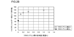
- FIG. 2B is a partially enlarged view showing the relationship between the content of phthalocyanine copper in the resin coating shown in FIG. 2A and the high torque performance.
- FIG. 3 is a block diagram showing an example of a metal pipe for an oil well according to the present embodiment.
- FIG. 4 is a partial cross-sectional view showing a cross section (longitudinal cross section) parallel to the pipe axis direction of the coupling of the metal pipe for oil well shown in FIG.
- FIG. 1 is a diagram showing the relationship between the rotation speed and torque of an oil well metal pipe when the oil well metal pipe having a shoulder portion is fastened.
- FIG. 2A is a diagram showing the relationship between the content of phthalocyanine copper in
- FIG. 5 is a cross-sectional view of the portion of the oil well metal pipe shown in FIG. 4 in the vicinity of the pin, which is parallel to the pipe axis direction of the oil well metal pipe.
- FIG. 6 is a cross-sectional view of the portion of the oil well metal pipe shown in FIG. 4 in the vicinity of the box, parallel to the pipe axis direction of the oil well metal pipe.
- FIG. 7 is a partial cross-sectional view showing a cross section (longitudinal cross section) parallel to the pipe axis direction of the coupling of the metal pipe for an oil well according to the present embodiment, which is different from FIG.
- FIG. 8 is a block diagram of an integral type metal pipe for an oil well according to the present embodiment.
- FIG. 9 is an enlarged view of the pin contact surface shown in FIG.
- FIG. 10 is an enlarged view of the box contact surface shown in FIG.
- FIG. 11 is an enlarged view of the pin contact surface according to the present embodiment different from that of FIG.
- FIG. 12 is an enlarged view of the pin contact surface according to the present embodiment, which is different from FIGS. 9 and 11.
- FIG. 13 is an enlarged view of the pin contact surface according to the present embodiment, which is different from FIGS. 9, 11 and 12.
- FIG. 14 is a diagram showing the relationship between the plating layer, the content of phthalocyanine copper, and the result of the Bowden test, which is an index of seizure resistance.
- FIG. 15 is an enlarged view of the box contact surface according to the present embodiment different from that of FIG. FIG.
- FIG. 16 is an enlarged view of the pin contact surface according to the present embodiment, which is different from FIGS. 9, 11, 12, and 13.
- FIG. 17 is an enlarged view of the pin contact surface according to the present embodiment, which is different from FIGS. 9, 11, 12, 13, and 16.
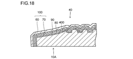
- FIG. 18 is an enlarged view of the pin contact surface according to the present embodiment, which is different from FIGS. 9, 11, 12, 13, 16, and 17.
- FIG. 19 is a diagram for explaining the torque on-shoulder resistance ⁇ T in the embodiment.
- the present inventors have conducted various studies on the relationship between the metal pipe for oil wells and the fastening torque. As a result, the following findings were obtained.
- FIG. 1 is a diagram showing the relationship between the rotation speed of an oil well metal pipe and the torque when the oil well metal pipe having a shoulder portion is fastened.
- the metal seal portions interfere with each other at an appropriate surface pressure.
- the metal tube for an oil well can be highly airtight.
- the difference between the shouldering torque Ts and the yield torque Ty is referred to as a torque-on-shoulder resistance ⁇ T.
- the metal pipe for oil wells there is a metal pipe for oil wells which does not have a shoulder part and has a wedge type screw (Wedge Thread).
- Wedge Thread wedge type screw
- the relationship between the rotation speed and the torque of the metal pipe for oil wells is as shown in FIG. 1, as in the case of the metal pipe for oil wells having a shoulder portion.
- the wedge-shaped screw means a screw having the following structure.
- the width of the thread gradually narrows along the chord winding of the screw and the width of the thread groove gradually widens along the chord winding of the screw with the traveling direction of screwing of the pin.
- the width of the thread groove gradually narrows along the chord winding of the screw and the width of the thread gradually widens along the chord winding of the screw with the traveling direction of screwing of the box.
- shouldering torque Ts locking torque and shouldering torque are not distinguished and are referred to as shouldering torque Ts.
- shouldering torque Ts In the case of a metal pipe for an oil well having a wedge-shaped screw, as in the case of a metal pipe for an oil well having a shoulder portion, if the shouldering torque Ts is reached and then the screw is further tightened, the screw is tightened rapidly in proportion to the number of revolutions. The torque rises. That is, in the shouldering torque Ts, the interference between the metal pipes for oil wells increases sharply. Then, if the screws are further tightened, the fastening torque To is reached. When the tightening torque To is reached and then excessively screwed, the yield torque Ty is reached and a part of the pin and the box yields.
- a high fastening torque To is set for the metal pipe for oil wells with a large diameter.
- the fastening torque To is set high, a part of the pin and the box may yield before reaching the fastening torque To, causing plastic deformation.
- the torque-on-shoulder resistance ⁇ T is large, the screws can be further tightened after reaching the shouldering torque Ts. Therefore, if the torque on-shoulder resistance ⁇ T is large, even a metal pipe for an oil well with a large diameter can be fastened with a high torque. In this case, the metal pipe for the oil well is difficult to loosen.
- high high torque performance means that the torque on-shoulder resistance ⁇ T is large.
- the metal pipe for an oil well having a large diameter means a metal pipe for an oil well having an outer diameter of 254 mm (10 inches) or more.
- the shouldering torque Ts and the yield torque Ty exhibit similar behaviors. For example, when the friction coefficient on the surface of the metal tubular tubular goods for oil well is lowered in order to reduce the shouldering torque Ts, not only the shouldering torque Ts but also the yield torque Ty is lowered. In this case, a part of the pin or the box may yield before reaching the fastening torque To. Further, when the friction coefficient on the surface of the metal tube for oil wells is increased in order to increase the yield torque Ty, not only the yield torque Ty but also the shouldering torque Ts is increased. In this case, the shoulder portion may not come into contact even when the fastening torque To is reached.
- FIG. 2A is a diagram showing the relationship between the content of phthalocyanine copper in the resin film and the high torque performance.
- FIG. 2A was obtained from the results of Example 1 described later.
- a metal tube for an oil well having a so-called large diameter (outer diameter 273.05 mm (10.75 inches), wall thickness: 12.570 mm (0.495 inches)) was used.
- the horizontal axis of FIG. 2A shows the content (mass%) of phthalocyanine copper in the resin coating.
- the vertical axis of FIG. 2A indicates the torque on-shoulder resistance ⁇ T.
- the torque-on-shoulder resistance ⁇ T is a relative value compared with the torque-on-shoulder resistance ⁇ T when the dope defined in the API (American Petroleum Institute) standard Bull 5A2 (1998) is used.
- the white circles ( ⁇ ) indicate that the resin film contained phthalocyanine copper
- the black circles ( ⁇ ) indicate that the resin film did not contain phthalocyanine copper.
- the torque on-shoulder resistance ⁇ T increases as compared with the case where the resin film does not contain phthalocyanine copper. That is, if the resin film contains phthalocyanine copper, the high torque performance is enhanced. In this case, even a metal pipe for an oil well with a large diameter can be fastened with a high torque.
- FIG. 2B is a partially enlarged view showing the relationship between the content of phthalocyanine copper in the resin film and the high torque performance. If the content of phthalocyanine copper in the resin film is adjusted to 0.2% by mass or more with reference to FIG. 2B, the high torque performance of the metal tube for oil wells is further enhanced.
- a metal pipe for oil wells It has a tube body that includes a first end and a second end, The tube body is The pin formed at the first end and Including the box formed at the second end The pin is Includes pin contact surface including male thread The box is Includes box contact surface including female thread The metal tube for oil wells is further described. A resin coating containing a resin, a solid lubricating powder, and phthalocyanine copper is provided on at least one of the pin contact surface and the box contact surface. Metal pipe for oil wells.
- the metal tube for an oil well according to this embodiment has a resin film containing phthalocyanine copper. Therefore, even a metal pipe for an oil well with a large diameter can be fastened with a high torque.
- the metal pipe for oil wells according to this embodiment can also be applied to a metal pipe for oil wells having a normal to small diameter.
- the oil well metal pipe according to the present embodiment can be fastened with a necessary and sufficient torque even when applied to an oil well metal pipe having a normal to small diameter.
- the metal pipe for oil wells according to [1].
- the resin film is Contains 0.2-30.0% by weight of phthalocyanine copper, Metal pipe for oil wells.
- the metal pipe for oil wells has higher high torque performance.
- the resin film is With 0.2 to 30.0% by mass of phthalocyanine copper, With 60 to 90% by mass of the resin, Containing 1 to 30% by mass of the solid lubricating powder.
- the metal pipe for an oil well according to [2] or [3].
- the resin film is Contains 0.2-9.0 mass% phthalocyanine copper, Metal pipe for oil wells.
- the metal pipe for oil wells has high seizure resistance in addition to high torque performance.
- the metal pipe for an oil well according to any one of [1] to [7].
- the resin coating further Contains rust preventive pigments, Metal pipe for oil wells.
- the metal pipe for an oil well according to any one of [1] to [8]. At least one of the pin contact surface and the box contact surface is a surface that has been subjected to one or more treatments selected from the group consisting of blast treatment and pickling. Metal pipe for oil wells.
- the metal pipe for an oil well according to any one of [1] to [9].
- the resin is One or more selected from the group consisting of epoxy resin, phenol resin, acrylic resin, urethane resin, polyester resin, polyamideimide resin, polyamide resin, polyimide resin, and polyether ether ketone resin.
- Metal pipe for oil wells is One or more selected from the group consisting of epoxy resin, phenol resin, acrylic resin, urethane resin, polyester resin, polyamideimide resin, polyamide resin, polyimide resin, and polyether ether ketone resin.
- the metal pipe for an oil well according to any one of [1] to [10].
- the solid lubricating powder is Selected from the group consisting of graphite, zinc oxide, boron nitride, talc, molybdenum disulfide, tungsten disulfide, graphite fluoride, tin sulfide, bismuth sulfide, organic molybdenum, thiosulfate compound, and polytetrafluoroethylene 1. More than a seed, Metal pipe for oil wells.
- the metal pipe for an oil well according to any one of [1] to [11].
- the pin contact surface further includes a pin seal surface and a pin shoulder surface.
- the box contact surface further includes a box seal surface and a box shoulder surface.
- the present invention comprises a step of curing the applied composition to form a resin film.
- Metal country pipes for oil wells have a well-known configuration.
- Oil well metal pipes include T & C type oil well metal pipes and integral type oil well metal pipes.
- each type of metal pipe for oil wells will be described in detail.
- FIG. 3 is a block diagram showing an example of a metal pipe 1 for an oil well according to the present embodiment.
- FIG. 3 is a block diagram of a so-called T & C type (Threaded and Coupled) metal tube 1 for an oil well.
- the oil well metal tube 1 includes a tube body 10.
- the pipe body 10 extends in the direction of the pipe axis.
- the cross section of the tube body 10 perpendicular to the tube axis direction is circular.
- the tube body 10 includes a first end portion 10A and a second end portion 10B.
- the first end 10A is the opposite end of the second end 10B.
- the tube body 10 includes a pin tube body 11 and a coupling 12.
- the coupling 12 is attached to one end of the pin tube 11. More specifically, the coupling 12 is fastened to one end of the pin tube 11 with a screw.
- FIG. 4 is a partial cross-sectional view showing a cross section (longitudinal cross section) parallel to the pipe axis direction of the coupling 12 of the oil well metal pipe 1 shown in FIG.
- the tube body 10 includes a pin 40 and a box 50.
- the pin 40 is formed at the first end portion 10A of the tube body 10.
- the pin 40 is inserted into the box 50 of another oil well metal tube 1 (not shown) and fastened to the box 50 of the other oil well metal tube 1 by a screw.
- the box 50 is formed at the second end portion 10B of the pipe body 10. At the time of fastening, the pin 40 of the other metal well for oil well 1 is inserted into the box 50 and fastened to the pin 40 of the other metal well for oil well 1 with a screw.
- FIG. 5 is a cross-sectional view of the portion of the oil well metal pipe 1 shown in FIG. 4 in the vicinity of the pin 40, which is parallel to the pipe axis direction of the oil well metal pipe 1.
- the broken line portion in FIG. 5 shows the configuration of the box 50 of the other oil well metal pipe 1 when it is fastened to the other oil well metal pipe 1.
- the pin 40 includes a pin contact surface 400 on the outer peripheral surface of the first end 10A of the tube body 10.
- the pin contact surface 400 is screwed into the box 50 of the other oil well metal pipe 1 at the time of fastening with the other oil well metal pipe 1, and comes into contact with the box contact surface 500 (described later) of the box 50.
- the pin contact surface 400 includes at least a male screw portion 41 formed on the outer peripheral surface of the first end portion 10A.
- the pin contact surface 400 may further include a pin seal surface 42 and a pin shoulder surface 43.
- the pin shoulder surface 43 is arranged on the tip surface of the first end portion 10A, and the pin seal surface 42 is located on the tip end side of the first end portion 10A of the outer peripheral surface of the first end portion 10A with respect to the male screw portion 41.
- the pin seal surface 42 is arranged between the male screw portion 41 and the pin shoulder surface 43.
- the pin seal surface 42 is provided in a tapered shape. Specifically, the outer diameter of the pin seal surface 42 gradually decreases from the male screw portion 41 toward the pin shoulder surface 43 in the longitudinal direction (pipe axis direction) of the first end portion 10A.
- the pin seal surface 42 comes into contact with the box seal surface 52 (described later) of the box 50 of the other oil well metal pipe 1. More specifically, at the time of fastening, the pin 40 is inserted into the box 50 of another oil well metal tube 1, so that the pin seal surface 42 comes into contact with the box seal surface 52. Then, the pin 40 is further screwed into the box 50 of the other oil well metal pipe 1, so that the pin seal surface 42 comes into close contact with the box seal surface 52. As a result, at the time of fastening, the pin seal surface 42 is in close contact with the box seal surface 52 to form a seal based on metal-metal contact. Therefore, the airtightness can be improved in the metal pipes 1 for oil wells fastened to each other.
- the pin shoulder surface 43 is arranged on the tip surface of the first end portion 10A. That is, in the pin 40 shown in FIG. 5, the male screw portion 41, the pin seal surface 42, and the pin shoulder surface 43 are arranged in this order from the center of the pipe body 10 toward the first end portion 10A.
- the pin shoulder surface 43 faces and contacts the box shoulder surface 53 (described later) of the box 50 of the other oil well metal pipe 1. More specifically, at the time of fastening, the pin 40 is inserted into the box 50 of the other metal tube 1 for oil wells, so that the pin shoulder surface 43 comes into contact with the box shoulder surface 53. As a result, a high torque can be obtained at the time of fastening. Further, the positional relationship between the pin 40 and the box 50 in the fastened state can be stabilized.
- the pin contact surface 400 of the pin 40 includes at least a male screw portion 41. That is, the pin contact surface 400 may include the male screw portion 41 and may not include the pin seal surface 42 and the pin shoulder surface 43.
- the pin contact surface 400 includes a male screw portion 41 and a pin shoulder surface 43, and may not include a pin seal surface 42.
- the pin contact surface 400 includes a male screw portion 41 and a pin seal surface 42, and may not include a pin shoulder surface 43.
- FIG. 6 is a cross-sectional view of the portion of the oil well metal pipe 1 in the vicinity of the box 50 shown in FIG. 4 parallel to the pipe axis direction of the oil well metal pipe 1.
- the broken line portion in FIG. 6 shows the configuration of the pin 40 of the other oil well metal pipe 1 when it is fastened to the other oil well metal pipe 1.
- the box 50 includes a box contact surface 500 on the inner peripheral surface of the second end 10B of the tube body 10. At the time of fastening to the other oil well metal tube 1, the box contact surface 500 is screwed into the pin 40 of the other oil well metal tube 1 and comes into contact with the pin contact surface 400 of the pin 40.
- the box contact surface 500 includes at least a female screw portion 51 formed on the inner peripheral surface of the second end portion 10B. At the time of fastening, the female threaded portion 51 meshes with the male threaded portion 41 of the pin 40 of the other metal well for oil well 1.
- the box contact surface 500 may further include a box seal surface 52 and a box shoulder surface 53.
- the box seal surface 52 is arranged on the pipe body 10 side of the inner peripheral surface of the second end portion 10B with respect to the female thread portion 51. That is, the box seal surface 52 is arranged between the female screw portion 51 and the box shoulder surface 53.
- the box seal surface 52 is provided in a tapered shape. Specifically, the inner diameter of the box seal surface 52 gradually decreases from the female thread portion 51 toward the box shoulder surface 53 in the longitudinal direction (pipe axis direction) of the second end portion 10B.
- the box seal surface 52 comes into contact with the pin seal surface 42 of the pin 40 of the other oil well metal pipe 1. More specifically, at the time of fastening, the box seal surface 52 comes into contact with the pin seal surface 42 when the pin 40 of the other oil well metal pipe 1 is screwed into the box 50, and further screwed into the box seal surface. 52 is in close contact with the pin seal surface 42. As a result, at the time of fastening, the box seal surface 52 is in close contact with the pin seal surface 42 to form a seal based on metal-metal contact. Therefore, the airtightness can be improved in the metal pipes 1 for oil wells fastened to each other.
- the box shoulder surface 53 is arranged on the pipe body 10 side with respect to the box seal surface 52. That is, in the box 50, the box shoulder surface 53, the box seal surface 52, and the female screw portion 51 are arranged in this order from the center of the pipe body 10 toward the tip of the second end portion 10B.
- the box shoulder surface 53 faces and contacts the pin shoulder surface 43 of the pin 40 of the other oil well metal pipe 1. More specifically, at the time of fastening, the box shoulder surface 53 comes into contact with the pin shoulder surface 43 by inserting the pin 40 of another metal tube 1 for an oil well into the box 50. As a result, a high torque can be obtained at the time of fastening. Further, the positional relationship between the pin 40 and the box 50 in the fastened state can be stabilized.
- the box contact surface 500 includes at least the female thread portion 51.
- the female threaded portion 51 of the box contact surface 500 of the box 50 corresponds to the male threaded portion 41 of the pin contact surface 400 of the pin 40 and comes into contact with the male threaded portion 41.
- the box seal surface 52 corresponds to the pin seal surface 42 and comes into contact with the pin seal surface 42.
- the box shoulder surface 53 corresponds to the pin shoulder surface 43 and comes into contact with the pin shoulder surface 43.
- the box contact surface 500 includes the female screw portion 51 and does not include the box seal surface 52 and the box shoulder surface 53.
- the box contact surface 500 includes the female screw portion 51 and the box shoulder surface 53 and does not include the box seal surface 52.
- the box contact surface 500 includes the female screw portion 51 and the box seal surface 52 and does not include the box shoulder surface 53.
- the pin contact surface 400 may include a plurality of male screw portions 41, may include a plurality of pin seal surfaces 42, or may include a plurality of pin shoulder surfaces 43.
- the pin shoulder surface 43, the pin seal surface 42, the male screw portion 41, the pin seal surface 42, the pin shoulder surface 43, and the pin seal surface toward the center of the tube body 10 from the tip of the first end portion 10A. 42 and the male screw portion 41 may be arranged in this order.
- the female thread portion 51, the box seal surface 52, the box shoulder surface 53, the box seal surface 52, and the female thread portion are directed from the tip of the second end portion 10B toward the center of the pipe body 10. 51, the box seal surface 52, and the box shoulder surface 53 are arranged in this order.
- the pin 40 includes a male screw portion 41, a pin seal surface 42, and a pin shoulder surface 43
- a box 50 includes a female screw portion 51, a box seal surface 52, and a box shoulder surface 53, so-called.
- Premium joints are illustrated.
- the pin 40 may include the male threaded portion 41 and may not include the pin seal surface 42 and the pin shoulder surface 43.
- the box 50 includes the female threaded portion 51 and does not include the box seal surface 52 and the box shoulder surface 53.
- the pin 40 includes the male threaded portion 41 and does not include the pin seal surface 42 and the pin shoulder surface 43
- the box 50 includes the female threaded portion 51 and does not include the box seal surface 52 and the box shoulder surface 53. It is a figure which shows an example of the metal pipe 1 for an oil well.
- the oil well metal tube 1 shown in FIGS. 3, 4 and 7 is a so-called T & C type oil well metal tube 1 in which the tube body 10 includes a pin tube body 11 and a coupling 12.
- the oil well metal tube 1 of the present embodiment may be an integral type instead of a T & C type.
- FIG. 8 is a configuration diagram of an integral type metal tube 1 for an oil well according to the present embodiment.
- the integral type metal well tube 1 includes a tube body 10.
- the tube body 10 includes a first end portion 10A and a second end portion 10B.
- the first end portion 10A is arranged on the opposite side of the second end portion 10B.
- the tube body 10 includes a pin tube body 11 and a coupling 12. That is, in the T & C type oil well metal tube 1, the tube body 10 is configured by fastening two separate members (pin tube body 11 and coupling 12).
- the pipe body 10 is integrally formed.
- the pin 40 is formed at the first end portion 10A of the pipe body 10. At the time of fastening, the pin 40 is inserted into and screwed into the box 50 of the other integral type oil well metal tube 1 and fastened to the box 50 of the other integral type oil well metal tube 1.
- the box 50 is formed at the second end portion 10B of the pipe body 10. At the time of fastening, the pin 40 of the other integral type oil well metal tube 1 is inserted into the box 50 and screwed into the box 50, and is fastened to the pin 40 of the other integral type oil well metal tube 1.
- the configuration of the pin 40 of the integral type oil well metal tube 1 is the same as the configuration of the pin 40 of the T & C type oil well metal tube 1 shown in FIG.
- the configuration of the box 50 of the integral type oil well metal tube 1 is the same as the configuration of the box 50 of the T & C type oil well metal tube 1 shown in FIG.
- the pin shoulder surface 43, the pin seal surface 42, and the male screw portion 41 are arranged in this order from the tip of the first end portion 10A toward the center of the tube main body 10. Therefore, in the box 50, the female screw portion 51, the box seal surface 52, and the box shoulder surface 53 are arranged in this order from the tip of the second end portion 10B toward the center of the pipe body 10.
- the pin contact surface 400 of the pin 40 of the integral type oil country tubular goods 1 should include at least the male thread portion 41. good.
- the box contact surface 500 of the box 50 of the T & C type oil well metal tube 1 should include at least the female thread portion 51. good.
- the oil well metal tube 1 of the present embodiment may be a T & C type or an integral type.
- the oil well metal tube 1 according to the present embodiment includes a resin coating 100 on at least one of a pin contact surface 400 and a box contact surface 500.
- FIG. 9 is an enlarged view of the pin contact surface 400 shown in FIG.
- FIG. 10 is an enlarged view of the box contact surface 500 shown in FIG.
- the oil well metal tube 1 according to the present embodiment may be provided with a resin coating 100 on both the pin contact surface 400 and the box contact surface 500.
- the oil well metal tube 1 according to the present embodiment may be provided with the resin coating 100 only on one of the pin contact surface 400 or the box contact surface 500. For example, as shown in FIG.
- the oil well metal tube 1 includes the resin coating 100 on the pin contact surface 400 and / or on the box contact surface 500.
- the resin coating 100 is a solid coating containing a resin, a solid lubricating powder, and phthalocyanine copper.
- the resin and the solid lubricating powder can be selected independently.
- the resin, the solid lubricating powder, and the phthalocyanine copper contained in the resin coating 100 according to the present embodiment will be described in detail.
- the resin contained in the resin film 100 according to the present embodiment is not particularly limited. However, when the metal pipe 1 for an oil well is fastened, the surface of the resin coating 100 is scraped to generate wear debris. Therefore, in order to stably obtain the wear resistance (coating life) of the resin coating 100 and the high torque performance, it is preferable to use a resin having a high adhesion to the substrate and an appropriate hardness. Resins having high adhesion to the substrate and having appropriate hardness are, for example, from epoxy resin, phenol resin, acrylic resin, urethane resin, polyester resin, polyamideimide resin, polyamide resin, polyimide resin, and polyether ether ketone resin. It is one or more species selected from the group of plastics.
- the resin is one or two selected from the group consisting of epoxy resin and acrylic resin.
- the content of the resin in the resin film 100 is, for example, 60 to 90% by mass. In this case, the moldability, seizure resistance, and high torque performance of the resin film 100 can be improved more stably.
- the lower limit of the resin content is preferably 62% by mass, more preferably 63% by mass, and even more preferably 65% by mass.
- the upper limit of the resin content is preferably 88% by mass, more preferably 86% by mass.
- Solid lubricating powder The solid lubricating powder contained in the resin coating 100 according to the present embodiment is not particularly limited. Solid lubricating powders are made from, for example, graphite, zinc oxide, boron nitride, talc, molybdenum disulfide, tungsten disulfide, graphite fluoride, tin sulfide, bismuth sulfide, organic molybdenum, thiosulfate compounds, and polytetrafluoroethylene. One or more species selected from the group of
- the solid lubricating powder is one or more selected from the group consisting of graphite, polytetrafluoroethylene, and molybdenum disulfide. More preferably, the solid lubricating powder is polytetrafluoroethylene.
- the content of the solid lubricating powder in the resin coating 100 is, for example, 1 to 30% by mass. In this case, the moldability and seizure resistance of the resin film 100 can be improved more stably.
- the lower limit of the content of the solid lubricating powder is preferably 2% by mass, more preferably 5% by mass.
- the upper limit of the content of the solid lubricating powder is preferably 25% by mass, more preferably 20% by mass.
- the resin coating 100 according to the present embodiment contains phthalocyanine copper.
- Phthalocyanine copper is the most important substance for exhibiting high torque performance in the metal pipe 1 for oil wells according to the present embodiment.
- Phthalocyanine Copper is a kind of phthalocyanine complex in which phthalocyanine (C 32 H 18 N 8 ) is coordinated to copper ion (Cu 2+ ). The chemical formula of phthalocyanine copper is shown below.
- the content of phthalocyanine copper in the resin film 100 according to this embodiment is not particularly limited. That is, if the resin film 100 contains even a small amount of phthalocyanine copper, the effect of enhancing the high torque performance of the metal tube 1 for oil wells can be obtained to some extent.
- the lower limit of the content of phthalocyanine copper in the resin film 100 may be 0.1% by mass.
- the lower limit of the content of phthalocyanine copper in the resin coating 100 is preferably 0.1% by mass, more preferably 0.2% by mass, and further preferably 0.4% by mass. be.
- the content of phthalocyanine copper in the resin coating 100 according to the present embodiment is 30.0% by mass or less, the dispersibility of phthalocyanine copper is enhanced. Therefore, the preferable upper limit of the content of phthalocyanine copper in the resin film 100 is 30.0% by mass. Further, when the content of phthalocyanine copper in the resin coating 100 according to the present embodiment is 9.0% by mass or less, the metal tube 1 for an oil well has not only high torque performance but also seizure resistance. Therefore, the upper limit of the content of phthalocyanine copper in the resin film 100 may be 9.0% by mass.
- the upper limit of the content of phthalocyanine copper in the resin coating 100 according to the present embodiment is preferably 30.0% by mass, more preferably 14.0% by mass, and further preferably 12.0% by mass. Yes, more preferably 10.0% by mass, still more preferably 9.0% by mass, still more preferably 6.0% by mass.
- Table 1 shows the content of phthalocyanine copper in the resin film 100 and the results of the Bowden test, which is an index of seizure resistance. Table 1 is a partial excerpt of the results of Example 2 described later.
- Example 2 a resin coating 100 containing phthalocyanine copper was formed on the surface of the steel sheet of each test number at the content shown in Table 1. Further, a Bowden test was carried out using the steel sheets of each test number on which the resin film 100 was formed. In the Bowden test, a steel ball was slid on the surface of the resin coating 100 of the steel plate of each test number to determine the coefficient of friction. Table 1 shows the content of phthalocyanine copper in the resin coating 100 of each test number and the number of slides until the friction coefficient exceeds 0.3. It should be noted that the larger the number of slides until the friction coefficient exceeds 0.3, the higher the seizure resistance.
- the resin coating 100 according to the present embodiment may further contain components other than those described above.
- the other component is, for example, one or more selected from the group consisting of rust preventives, preservatives, and antioxidants.
- the rust inhibitor is, for example, one or more selected from the group consisting of aluminum tripolyphosphate, aluminum phosphite, and calcium ion exchange silica.
- a commercially available water repellent may be used as the rust preventive.
- the resin coating 100 may be a single layer or may include a plurality of layers. "Containing a plurality of layers” means a state in which two or more layers of the resin coating 100 are laminated in the radial direction of the metal tube 1 for an oil well. By repeating the application and curing of the composition for forming the resin film 100, the resin film 100 can be formed by laminating two or more layers.
- the resin coating 100 may be formed directly on at least one of the pin contact surface 400 and the box contact surface 500, and the surface treatment described later may be performed on the pin contact surface 400 and / or the box contact surface 500. It may be formed.
- the resin coating 100 contains a plurality of layers
- any one of the resin coatings 100 may contain each component within the above range, and all of the plurality of resin coatings 100 contain each component within the above range. You may.
- the resin coating 100 includes a rust-preventive resin coating.
- the rust-preventive resin coating has an arbitrary configuration. That is, the rust-preventive resin film does not have to be formed in the oil well metal pipe 1 according to the present embodiment.
- the rust preventive resin coating will be described in detail.
- the oil well metal tube 1 may further include a rust-preventive resin film in the resin film 100 formed on at least one of the pin contact surface 400 and the box contact surface 500.
- the rust-preventive resin film contains a rust-preventive pigment and an acrylic silicone resin.
- the rust-preventive pigment is, for example, one or more selected from the group consisting of aluminum tripolyphosphate, aluminum phosphite, zinc rich primer (JIS K5552 (2010)) and mica-like iron oxide.
- the acrylic silicone resin a commercially available acrylic silicone resin can be used.
- the commercially available acrylic silicone resin is, for example, acrylic silicone resin acridic manufactured by DIC Corporation.
- the content of the rust-preventive pigment in the rust-preventive resin film is, for example, 5 to 30% by mass.
- the content of the acrylic silicone resin in the rust-preventive resin film is, for example, 50 to 80% by mass.
- the rust-preventive resin film may contain other components in addition to the rust-preventive pigment and the acrylic silicone resin.
- the other component is, for example, one or more selected from the group consisting of pigments, antifoaming agents, leveling agents and fibrous fillers.
- the content of other components in the rust-preventive resin coating is, for example, 0 to 20% by mass in total.
- the rust preventive resin film is included in the resin film 100.
- FIG. 11 is an enlarged view of the pin contact surface 400 according to the present embodiment different from that of FIG.
- the oil well metal tube 1 includes a rust-preventive resin film 70 and an upper layer 60 of the resin film 100 in a resin film 100 formed on the pin contact surface 400.
- the upper layer 60 of the resin film 100 contains a resin, a solid lubricating powder, and phthalocyanine copper
- the rust-preventive resin film 70 which is the lower layer of the resin film 100, contains a rust-preventive pigment and an acrylic silicon resin. do.
- the oil well metal tube 1 may include a rust-preventive resin film 70 in the resin film 100 formed on the box contact surface 500.
- the rust-preventive resin coating 70 is also included only in the resin coating 100 formed on the pin contact surface 400, and may not be included in the resin coating 100 formed on the box contact surface 500.
- the rust-preventive resin coating 70 may not be further included in the resin coating 100 formed on the pin contact surface 400, but may be included only in the resin coating 100 formed on the box contact surface 500.
- the rust-preventive resin coating 70 may be further contained in both the resin coating 100 formed on the pin contact surface 400 and the resin coating 100 formed on the box contact surface 500.
- the rust-preventive resin film 70 may be contained in the resin film 100 formed on the plating layer described later, or may be contained in the resin film 100 formed on the chemical conversion film described later. good. That is, in the present embodiment, the rust preventive resin coating 70 may be formed on the pin contact surface 400, on the box contact surface 500, or on the plating layer described later. It may be formed on a chemical conversion film described later.
- the resin coating 100 may be arranged as the outermost layer on the pin contact surface 400 and / or on the box contact surface 500. At the time of fastening the metal pipe 1 for an oil well, a liquid lubricant may be further applied on the resin film 100.
- the thickness of the resin film 100 is not particularly limited.
- the thickness of the resin coating 100 is, for example, 1 to 100 ⁇ m. In this case, the high torque performance of the oil well metal pipe 1 can be improved more stably.
- the lower limit of the thickness of the resin coating 100 is preferably 2 ⁇ m, more preferably 5 ⁇ m, and even more preferably 10 ⁇ m.
- the upper limit of the thickness of the resin film 100 is preferably 80 ⁇ m, more preferably 70 ⁇ m, still more preferably 60 ⁇ m, still more preferably 50 ⁇ m.
- the thickness of the resin film 100 is measured by the following method.
- the probe of the electromagnetic induction type film thickness measuring instrument is brought into contact with the pin contact surface 400 or the box contact surface 500 on which the resin film 100 is formed.
- the probe has an electromagnet, and when a magnetic material is brought close to it, electromagnetic induction occurs, and its voltage changes depending on the distance between the probe and the magnetic material.
- the thickness of the resin coating 100 is obtained from the change in the amount of voltage.
- the arithmetic mean of the measurement results at 12 points is defined as the thickness of the resin coating 100.
- the resin coating 100 may be formed directly on the pin contact surface 400 or the box contact surface 500 in contact with the pin contact surface 400 or the box contact surface 500.
- the oil well metal tube 1 may further include another coating between the pin contact surface 400 or the box contact surface 500 and the resin coating 100.
- the other coating is, for example, one or more coatings selected from the group consisting of a plating layer and a chemical conversion coating.
- the oil well metal tube 1 according to the present embodiment may further include a plating layer between at least one of the pin contact surface 400 and the box contact surface 500 and the resin coating 100.
- the plating layer has an arbitrary structure. That is, the plating layer does not have to be formed in the metal tube 1 for oil wells according to the present embodiment.
- FIG. 12 is an enlarged view of the pin contact surface 400 according to the present embodiment, which is different from FIGS. 9 and 11.
- the plating layer 80 is arranged between the pin contact surface 400 and the resin coating 100.
- the plating layer 80 is formed on the pin contact surface 400
- the resin coating 100 is formed on the plating layer 80.
- the arrangement of the plating layer 80 is not limited to FIG.
- the plating layer 80 may be arranged between the box contact surface 500 and the resin coating 100.
- the plating layer 80 may be arranged between the pin contact surface 400 and the resin coating 100, and neither the resin coating 100 nor the plating layer 80 may be arranged on the box contact surface 500.
- the plating layer 80 may be arranged between the pin contact surface 400 and the resin coating 100, and the plating layer 80 may be arranged between the box contact surface 500 and the resin coating 100.
- FIG. 13 is an enlarged view of the pin contact surface 400 according to the present embodiment, which is different from FIGS. 9, 11 and 12.
- the plating layer 80 may be arranged between the pin contact surface 400 and the resin coating 100, and the resin coating 100 may include the rust preventive resin coating 70 and the upper layer 60 of the resin coating 100. ..
- the type of the plating layer 80 is not particularly limited.
- the plating layer 80 is selected from the group consisting of, for example, a Zn plating layer, a Ni plating layer, a Cu plating layer, a Zn—Ni alloy plating layer, a Zn—Co alloy plating layer, and a Ni—W alloy plating layer.
- the chemical composition of the Zn—Ni alloy plating layer is, for example, 10 to 20% by mass of Ni, and the balance is Zn and impurities.
- the chemical composition of the Cu plating layer comprises, for example, Cu and impurities.
- the seizure resistance of the oil well metal tube 1 is further enhanced.
- FIG. 14 is a diagram showing the relationship between the plating layer 80, the content of phthalocyanine copper, and the result of the Bowden test, which is an index of seizure resistance.
- FIG. 14 was obtained from Example 2 described later.
- the horizontal axis of FIG. 14 shows the content of phthalocyanine copper in the resin film 100.
- the vertical axis of FIG. 14 shows the number of slides until the friction coefficient exceeds 0.3.
- Example 2 a steel ball was slid on the surface of the steel plate on which the plating layer 80 and / or the resin coating 100 was formed, and the number of sliding times until the friction coefficient exceeded 0.3 was measured. The greater the number of slides until the friction coefficient exceeds 0.3, the higher the seizure resistance.
- Example 2 a steel ball was slid on the surface of the steel plate on which the plating layer 80 and / or the resin coating 100 was formed, and the number of sliding times until the friction coefficient exceeded 0.3 was measured. The greater the number of slides until the friction coefficient exceeds 0.3
- white circles ( ⁇ ) indicate that the plating layer 80 was not formed on the surface of the steel sheet, but only the resin coating 100 was formed.
- square marks ( ⁇ ) indicate that a Zn—Ni alloy plating layer was formed on the surface of the steel sheet, and a resin film 100 was formed on the Zn—Ni alloy plating layer.
- the oil well metal pipe 1 provided with the Zn—Ni alloy plating layer slides until the friction coefficient exceeds 0.3 as compared with the oil well metal pipe 1 not provided with the plating layer 80. There are many movements. As described above, the oil well metal tube 1 in which the plating layer 80 is formed on the pin contact surface 400 and / or the box contact surface 500 is further enhanced in seizure resistance.
- the thickness of the plating layer 80 is not particularly limited.
- the thickness of the plating layer 80 is, for example, 1 to 30 ⁇ m. In this case, the seizure resistance of the oil well metal pipe 1 can be improved more stably.
- the lower limit of the thickness of the plating layer 80 is preferably 2 ⁇ m, more preferably 3 ⁇ m, and even more preferably 4 ⁇ m.
- the upper limit of the thickness of the plating layer 80 is preferably 20 ⁇ m, more preferably 10 ⁇ m.
- the thickness of the plating layer 80 is measured by the following method.
- the probe of the electromagnetic induction type film thickness measuring device is brought into contact with the pin contact surface 400 or the box contact surface 500 on which the plating layer 80 is formed.
- the probe is contacted at the portion of the pin contact surface 400 or the box contact surface 500 from which the resin coating 100 has been removed.
- the probe has an electromagnet, and when a magnetic material is brought close to it, electromagnetic induction occurs, and its voltage changes depending on the distance between the probe and the magnetic material.
- the thickness of the plating layer 80 is obtained from the change in the amount of voltage.
- the oil well metal tube 1 according to the present embodiment may further include a chemical conversion film between at least one of the pin contact surface 400 and the box contact surface 500 and the resin film 100.
- the chemical conversion film has an arbitrary structure. That is, the chemical conversion film does not have to be formed in the metal tube 1 for oil wells according to the present embodiment.
- FIG. 15 is an enlarged view of the box contact surface 500 according to the present embodiment, which is different from FIG. 10.
- the chemical conversion coating 90 is arranged between the box contact surface 500 and the resin coating 100.
- the chemical conversion film 90 is formed on the box contact surface 500
- the resin film 100 is formed on the chemical conversion film 90.
- the arrangement of the chemical conversion coating 90 is not limited to FIG.
- the chemical conversion coating 90 may be arranged between the pin contact surface 400 and the resin coating 100, and neither the resin coating 100 nor the chemical conversion coating 90 may be arranged on the box contact surface 500.
- the chemical conversion coating 90 may be arranged between the pin contact surface 400 and the resin coating 100, and the chemical conversion coating 90 may be further arranged between the box contact surface 500 and the resin coating 100.
- FIG. 16 is an enlarged view of the pin contact surface 400 according to the present embodiment, which is different from FIGS. 9, 11, 12, and 13.
- the chemical conversion film 90 may be arranged between the pin contact surface 400 and the resin film 100, and the resin film 100 may include the rust preventive resin film 70 and the upper layer 60 of the resin film 100. ..
- the pin contact surface 400 and the box contact surface 500 according to the present embodiment may further include both the plating layer 80 and the chemical conversion coating 90.
- FIG. 17 is an enlarged view of the pin contact surface 400 according to the present embodiment, which is different from FIGS. 9, 11, 12, 13, and 16.
- the plating layer 80 is arranged on the pin contact surface 400
- the chemical conversion coating 90 is arranged on the plating layer 80
- the resin coating 100 is arranged on the chemical conversion coating 90. That is, when the plating layer 80 is provided, the oil well metal tube 1 includes a chemical conversion coating 90 between the plating layer 80 and the resin coating 100.
- the arrangement of the plating layer 80 and the chemical conversion coating 90 in the metal tube 1 for oil wells according to the present embodiment is not limited to FIG. 17, but the plating layer 80 and the chemical conversion coating 90 are formed between the pin contact surface 400 and the resin coating 100.
- the chemical conversion coating 90 may be arranged on the plating layer 80, and the resin coating 100 may be arranged on the chemical conversion coating 90.
- the chemical conversion coating 90 may be arranged on the pin contact surface 400 and the resin coating 100 and the resin coating 100 may be arranged on the chemical conversion coating 90. ..
- the chemical conversion coating 90 is arranged on the plating layer 80 and the resin coating 100 is arranged on the chemical conversion coating 90. May be done.
- the chemical coating 90 may be arranged on the box contact surface 500, and the resin coating 100 may be arranged on the chemical coating 90. ..
- FIG. 18 is an enlarged view of the pin contact surface 400 according to the present embodiment, which is different from FIGS. 9, 11, 12, 13, 16 and 17.
- the plating layer 80 is arranged on the pin contact surface 400
- the chemical conversion film 90 is arranged on the plating layer 80
- the resin film 100 is arranged on the chemical conversion film 90
- the resin film 100 is rust-proof.
- the resin film 70 and the upper layer 60 of the resin film 100 may be included.
- the type of the chemical conversion coating 90 is not particularly limited.
- the chemical conversion coating 90 is selected from the group consisting of, for example, a phosphate chemical conversion coating, a oxalate chemical conversion coating, a boronic acid chemical conversion coating, and a chromate coating. From the viewpoint of the adhesion of the resin film 100, a phosphate chemical conversion film is preferable.
- the phosphate is one or more selected from the group consisting of, for example, manganese phosphate, zinc phosphate, iron manganese phosphate, or zinc calcium phosphate.
- the chemical conversion coating 90 may be a chromate coating.
- the chromate film may be formed by a well-known method.
- the chromate coating preferably does not contain hexavalent chromium.
- the seizure resistance of the oil well metal tube 1 is further enhanced.
- the chemical film 90 enhances the adhesion of the resin film 100 on the chemical film 90 by the anchor effect.
- the seizure resistance of the metal pipe 1 for oil wells is enhanced.
- the oil well metal tube 1 in which the chemical conversion coating 90 is formed on the pin contact surface 400 and / or the box contact surface 500 is further enhanced in seizure resistance.
- the oil well metal tube 1 of the present embodiment may be provided with the resin coating 100 on at least one of the pin contact surface 400 and the box contact surface 500.
- the arrangement of the plating layer 80, the chemical conversion film 90, and the rust preventive resin film 70 may be the same or different on the pin contact surface 400 and the box contact surface 500.
- the oil well metal tube 1 may be further provided with another coating, if necessary.
- the pin contact surface 400 and the box contact surface 500 may be a surface that has been subjected to a base treatment. That is, in the present embodiment, the surface treatment is an arbitrary step, and neither the pin contact surface 400 nor the box contact surface 500 may be a surface that has been subjected to the surface treatment.
- the substrate treatment is, for example, one or more selected from the group consisting of blasting and pickling. If the surface treatment is applied, the surface roughness of the pin contact surface 400 and / or the box contact surface 500 is increased. Therefore, the adhesion of the resin coating 100, the plating layer 80 and / or the chemical conversion coating 90 formed on the resin coating 100 is enhanced. As a result, the seizure resistance of the metal pipe 1 for oil wells is enhanced.
- the chemical composition of the pipe body 10 of the metal tube 1 for oil wells according to the present embodiment is not particularly limited.
- the feature of the metal tube 1 for oil wells of this embodiment is the resin coating 100. Therefore, in the present embodiment, the steel type of the pipe body 10 of the metal pipe 1 for oil wells is not particularly limited.
- the pipe body 10 may be formed of, for example, carbon steel, stainless steel, an alloy, or the like. That is, the metal pipe for an oil well may be a steel pipe made of an Fe-based alloy or an alloy pipe typified by a Ni-based alloy pipe.
- the steel pipe is, for example, a low alloy steel pipe, a martensitic stainless steel pipe, a duplex stainless steel pipe, or the like.
- high alloy steels such as Ni-based alloys and two-phase stainless steels containing alloying elements such as Cr, Ni and Mo have high corrosion resistance. Therefore, if these high alloy steels are used as the pipe body 10, excellent corrosion resistance can be obtained in a corrosive environment containing hydrogen sulfide, carbon dioxide, and the like.
- the method for manufacturing the metal tube 1 for an oil well includes a preparation step, a coating step, and a curing step.
- the curing step is carried out after the coating step.
- a metal tubular goods 1 for an oil well is prepared, which comprises a pipe body 10 including a pin 40 including a pin contact surface 400 including a male screw portion 41 and a box 50 including a box contact surface 500 including a female screw portion 51.
- the metal tubular goods 1 for oil wells according to the present embodiment has a well-known configuration. That is, in the preparation step, the metal tube 1 for an oil well having a well-known structure may be prepared.
- a composition containing a resin, a solid lubricating powder and phthalocyanine copper is applied onto at least one of the pin contact surface 400 and the box contact surface 500.
- the composition is a composition for forming the above-mentioned resin film 100.
- the composition contains a resin, a solid lubricating powder and phthalocyanine copper.
- the composition of the composition for forming the resin film 100 excluding the solvent is the same as the composition of the resin film 100 described above.
- the solvent-free composition can be produced, for example, by heating the resin to a molten state, adding solid lubricating powder and phthalocyanine copper, and kneading.
- a powder mixture in which all the components are mixed in the form of powder may be used as a composition.
- the solvent-type composition can be produced, for example, by dissolving or dispersing a resin, a solid lubricating powder and phthalocyanine copper in a solvent and mixing them.
- the solvent is, for example, water, alcohol, and an organic solvent.
- the solvent may contain trace amounts of surfactant.
- the ratio of the solvent is not particularly limited. The ratio of the solvent may be adjusted so that the composition has an appropriate viscosity depending on the coating method.
- the ratio of the solvent is, for example, 40 to 60% by mass when the total of all the components other than the solvent is 100% by mass.
- the method of applying the composition on the pin contact surface 400 and / or the box contact surface 500 is not particularly limited, and a well-known method may be used.
- the composition can be applied, for example, onto the pin contact surface 400 and / or the box contact surface 500 using a hot melt method.
- the hot melt method the composition is heated to melt the resin and bring it into a low-viscosity fluid state.
- the fluidized composition is sprayed from a spray gun having a temperature retention function.
- the method of applying the composition on the pin contact surface 400 and / or the box contact surface 500 may be brush coating, dipping or the like instead of spray coating.
- the heating temperature of the composition is preferably 10 to 50 ° C. higher than the melting point of the resin.
- the composition in a solution state can be applied onto the pin contact surface 400 and / or the box contact surface 500 by spraying.
- the viscosity of the composition is adjusted so that it can be spray-applied in an environment of normal temperature and pressure.
- the method of applying the composition on the pin contact surface 400 and / or the box contact surface 500 may be brush coating, dipping or the like instead of spray coating.
- the applied composition is cured to form the resin film 100.
- the cooling method is not particularly limited, and a well-known method may be used.
- the cooling method is, for example, atmospheric cooling and air cooling.
- the drying method is not particularly limited, and a well-known method may be used.
- the drying method is, for example, natural drying, low temperature blast drying and vacuum drying.
- the resin is a thermosetting resin
- the composition may be cured by a thermosetting treatment to form a solid resin film 100.
- the oil well metal tube 1 of the present embodiment is manufactured by the above manufacturing process.
- the method for manufacturing the metal pipe 1 for an oil well of the present embodiment may further include any one or more of a plating layer forming step, a chemical conversion treatment step, a rust preventive resin film forming step, and a base treatment step. All of these steps are arbitrary steps. Therefore, these steps do not have to be performed.
- the method for manufacturing a metal tube 1 for an oil well may further include a plating layer forming step before the coating step.
- the plating layer 80 is formed on at least one of the pin contact surface 400 and the box contact surface 500.
- the method for forming the plating layer 80 is not particularly limited, and a well-known method may be used.
- the plating layer 80 may be formed by electrolytic plating or electroless plating.
- the plating bath contains zinc ions and nickel ions.
- the composition of the plating bath preferably contains zinc ions: 1 to 100 g / L and nickel ions: 1 to 50 g / L.
- the conditions for electrolytic plating are, for example, plating bath pH: 1 to 10, plating bath temperature: 20 to 60 ° C., current density: 1 to 100 A / dm 2 , and treatment time: 0.1 to 50 minutes.
- the Cu plating layer is formed by electrolytic plating, it can be carried out by a well-known method.
- the method for manufacturing a metal tube 1 for an oil well may further include a chemical conversion treatment step before the coating step.
- a chemical conversion coating 90 is formed on at least one of the pin contact surface 400 and the box contact surface 500.
- the method of chemical conversion treatment is not particularly limited, and a well-known method may be used.
- the chemical conversion treatment is selected from the group consisting of, for example, a phosphate chemical conversion treatment, a oxalate chemical conversion treatment, a boron chemical conversion treatment, and a chromate treatment.
- As the treatment liquid for the chemical conversion treatment an acidic phosphate chemical conversion treatment liquid for a general galvanized material can be used.
- a zinc phosphate-based chemical conversion treatment containing 1 to 150 g / L of phosphate ion, 3 to 70 g / L of zinc ion, 1 to 100 g / L of nitrate ion, and 0 to 30 g / L of nickel ion can be used.
- a manganese phosphate-based chemical conversion treatment liquid commonly used in the metal tube 1 for oil wells can also be used.
- a commercially available chromate treatment liquid can also be used as the treatment liquid.
- the liquid temperature of the treatment liquid is, for example, from room temperature to 100 ° C.
- the treatment time of the chemical conversion treatment can be appropriately set according to the desired film thickness, and is, for example, 0.5 to 15 minutes.
- the surface adjustment may be performed before the chemical conversion treatment.
- the surface adjustment means a treatment of immersing in a surface adjustment aqueous solution containing colloidal titanium.
- the chemical conversion coating 90 is formed on any one of the pin contact surface 400, the box contact surface 500, and the plating layer 80. That is, in the method for manufacturing the metal pipe 1 for an oil well according to the present embodiment, when both the plating layer forming step and the chemical conversion treatment step are carried out, the chemical conversion treatment step is carried out after the plating layer forming step, and then the coating is applied. Carry out the process.
- the method for manufacturing a metal tube 1 for an oil well may further include a rust-preventive resin film forming step before the coating step.
- the rust-preventive resin film forming step is carried out, the rust-preventive resin film 70 is formed on at least one of the pin contact surface 400, the box contact surface 500, the plating layer 80, and the chemical conversion film 90.
- the method for forming the rust-preventive resin film 70 is not particularly limited, and a well-known method may be used.
- the rust-preventive resin film 70 is, for example, a composition containing a rust-preventive pigment and an acrylic silicon resin on at least one of a pin contact surface 400, a box contact surface 500, a plating layer 80, and a chemical conversion film 90. Can be formed by applying to and curing the composition.
- the coating method is not particularly limited, and spray coating, brush coating, and dipping may be used.
- the composition for forming the rust-preventive resin film 70 may contain a solvent.
- the composition of the composition for forming the rust-preventive resin film 70 excluding the solvent is the same as the composition of the rust-preventive resin film 70 described above.
- the curing method is, for example, natural drying, low temperature air drying and heat drying.
- the rust preventive resin coating 70 is on any of the pin contact surface 400, the box contact surface 500, the plating layer 80, and the chemical conversion coating 90. Is formed in. That is, in the method of manufacturing the metal tube 1 for an oil well according to the present embodiment, when all of the plating layer forming step, the chemical conversion treatment step and the rust-preventive resin film forming step are carried out, the plating layer forming step, the chemical conversion treatment step and the rust-preventive resin The film forming step is carried out in this order, and then the coating step is carried out.
- the method for manufacturing a metal tube 1 for an oil well may further include a base treatment step before the coating step.
- the method for manufacturing the metal tube 1 for an oil well may include a base treatment step before the plating layer forming step.
- the method for manufacturing the metal tube 1 for an oil well may include a base treatment step before the chemical conversion treatment step.
- the method for manufacturing the metal tube 1 for an oil well may carry out a base treatment step before carrying out the rust-preventive resin film forming step.
- a pickling treatment and / or a blast treatment is carried out.
- alkaline degreasing treatment may be performed.
- the pin contact surface 400 and / or the box contact surface 500 is immersed in a strong acid solution such as sulfuric acid, hydrochloric acid, nitric acid, hydrofluoric acid, or a mixed acid thereof, and the pin contact surface 400 is immersed. And / or increase the surface roughness of the box contact surface 500.
- a strong acid solution such as sulfuric acid, hydrochloric acid, nitric acid, hydrofluoric acid, or a mixed acid thereof
- the pin contact surface 400 is immersed.
- a strong acid solution such as sulfuric acid, hydrochloric acid, nitric acid, hydrofluoric acid, or a mixed acid thereof
- the pin contact surface 400 is immersed.
- a strong acid solution such as sulfuric acid, hydrochloric acid, nitric acid, hydrofluoric acid, or a mixed acid thereof
- the pin contact surface 400 is immersed.
- a strong acid solution such as sulfuric acid, hydrochloric acid, nitric acid, hydrofluoric acid
- the same treatment may be performed on the pin contact surface 400 and the box contact surface 500, or different treatments may be performed. Further, these treatments may be performed only on the pin contact surface 400 or only on the box contact surface 500.
- the metal pipe 1 for an oil well according to the present embodiment is manufactured.
- the above-mentioned manufacturing method is an example of the manufacturing method of the metal tube 1 for an oil well according to the present embodiment, and is not limited to this manufacturing method.
- the metal tube 1 for an oil well according to the present embodiment may be manufactured by another method.
- Example 1 a resin film 100 was formed on the pin contact surface 400 or the box contact surface 500 of the metal tube 1 for an oil well, and high torque performance and seizure resistance were evaluated.
- a metal tube for oil wells manufactured by Nippon Steel Corporation VAM21 (registered trademark) HT (outer diameter 273.05 mm (10.75 inches), wall thickness: 12.570 mm (0.495 inches)). )) was used.
- the steel grade of the metal pipe for oil wells is SM2535M110 steel (C ⁇ 0.03%, Si: ⁇ 0.50%, Mn ⁇ 1.0%, Cu ⁇ 1.5%, Ni: 29.5 to 36.5%. , Cr: 24.0 to 27.0%, balance: Fe and impurities).
- a plating layer and a resin film containing a rust-preventive resin film were appropriately formed on the contact surface of the box of test numbers 1 to 12, and a metal tube for an oil well including a pin and a box of test numbers 1 to 12 was prepared. ..
- the formed plating layer is shown in the "plating layer” column in Table 2.
- "-" In the "plating layer” column in Table 2 means that the plating layer was not formed.
- the thickness of each of the formed plating layers was 8 ⁇ m. The thickness of the plating layer was measured by the above method using an electromagnetic film thickness meter SDM-pic MechanismR manufactured by Sanko Electronics Laboratory Co., Ltd.
- the plating layer was not formed. Therefore, in Test No. 1, a resin film was formed directly on the box contact surface. Further, in Test No. 10, an upper layer of the resin film was formed on the rust-preventive resin film. That is, in test number 10, the resin coating was a multi-layer.
- Table 2 shows the content of phthalocyanine copper in the formed resin coating for each test number.
- the formed resin film further contained 1 to 30% by mass of polytetrafluoroethylene (PTFE) as a solid lubricating powder, and the balance contained an epoxy resin as a resin.
- PTFE polytetrafluoroethylene
- the formed resin film did not contain phthalocyanine copper.
- the resin coating contained 8.6% by mass of Cr 2 O 3 instead of phthalocyanine copper.
- the resin coating of Test No. 12 further contained 1 to 30% by mass of polytetrafluoroethylene (PTFE) as a solid lubricating powder, and the balance contained an epoxy resin as a resin.
- PTFE polytetrafluoroethylene
- the composition of the Zn—Ni alloy plating layer was Zn: 85% and Ni: 15%. Further, a trivalent chromate film was formed on the obtained Zn—Ni alloy plating layer.
- As the treatment liquid for forming the trivalent chromate film Dine Chromate TR-02 manufactured by Daiwa Kasei Co., Ltd. was used.
- the conditions for the chemical conversion treatment were a bath temperature of 25 ° C., a pH of 4.0, and a treatment time of 50 seconds.
- a resin film was formed on the box contact surfaces of test numbers 1 to 12. In test numbers 2 to 9, 11 and 12, a resin film was formed on the box contact surface on which the plating layer was formed. In Test No. 1, a resin film was formed directly on the surface of the box contact. In Test No. 10, an upper layer of the resin film was formed on the rust-preventive resin film.
- a composition for forming a resin film was spray-coated on the box contact surface, the Zn—Ni alloy plating layer, or the rust-preventive resin film, and cured. As described above, in the composition, the components other than the solvent contained polytetrafluoroethylene particles and phthalocyanine copper, and the balance was an epoxy resin.
- the composition further contained a solvent.
- a solvent a mixed solution of water, alcohol and a surfactant was used.
- the composition was spray-coated on the Zn—Ni alloy plating layer on the surface of the box, and then heat-cured at 210 ° C. for 20 minutes to form a resin film.
- phthalocyanine copper was not used, and Cr 2O 3 was used in an amount of 8.6% by mass instead.
- the torque-on-shoulder resistance ⁇ T was measured using a metal tube for an oil well having a pin contact surface and a box contact surface of test numbers 1 to 12. Specifically, the fastening torque value was gradually increased at a tightening speed of 10 rpm, and the test was terminated when the material yielded. The torque was measured at the time of screw tightening, and a torque chart as shown in FIG. 19 was created. Ts in FIG. 19 means shouldering torque. MTV in FIG. 19 means a torque value at which the line segment L and the torque chart intersect. The line segment L is a straight line having the same slope as the slope of the linear region in the torque chart after shouldering, and the number of rotations is 0.2% higher than that of the linear region.
- test numbers 1-10 provided a resin coating containing resin, solid lubricating powder and phthalocyanine copper on at least one of the pin contact surface and the box contact surface. Therefore, the torque on-shoulder resistance ⁇ T of test numbers 1 to 10 was 100 or more, showing excellent high torque performance.
- the metal tube for oil wells of test numbers 1 and 3 to 10 had a phthalocyanine copper content of 0.2 to 30.0% by mass in the resin coating. Therefore, the oil well metal pipes of Test Nos. 1 and 3 to 10 had a higher torque-on-shoulder resistance ⁇ T as compared with Test No. 2 having a phthalocyanine copper content of less than 0.2% by mass.
- Example 2 a resin film was formed on the surface of a steel plate simulating a metal tube for an oil well, and the seizure resistance was evaluated. Specifically, in Example 2, cold-rolled steel sheets (chemical composition: C ⁇ 0.15%, Mn ⁇ 0.60%, P ⁇ 0.100%, S ⁇ 0.050%, balance: Fe and impurities. ) was used.
- the plating layer shown in Table 3 was appropriately formed on the surfaces of the steel plates of test numbers 13 to 21.
- the formed plating layer is shown in the "plating layer” column in Table 3.
- "-" In the “plating layer” column in Table 3 means that the plating layer was not formed.
- the thickness of each of the formed plating layers was 8 ⁇ m.
- a resin film was formed on the surfaces of the steel plates of test numbers 13 to 17 and 21. In test numbers 18 to 20, a resin film was formed on the formed plating layer. The thickness of each of the formed resin coatings was 20 ⁇ m.
- the thickness of the resin film was measured using an electromagnetic film thickness meter SDM-pic WhyR manufactured by Sanko Denshi Kenkyusho Co., Ltd., and the average value of the thickness at 9 points on the same evaluation surface was taken as the thickness of the resin film. did. Further, Table 3 shows the content of phthalocyanine copper in the formed resin film.
- the formed resin film further contained 1 to 30% by mass of polytetrafluoroethylene (PTFE) as a solid lubricating powder, and the balance contained an epoxy resin as a resin.
- PTFE polytetrafluoroethylene
- a Zn—Ni alloy plating layer was formed on the surface of the steel sheets of test numbers 18 to 20 by electroplating.
- Dynezin Alloy N-PL (trademark) manufactured by Daiwa Kasei Co., Ltd. was used.
- the thickness of the Zn—Ni alloy plating layer was 8 ⁇ m.
- the thickness of the plating layer was measured using an electromagnetic film thickness meter SDM-pic MechanismR manufactured by Sanko Denshi Kenkyusho Co., Ltd., and the average value of the thickness at 9 points on the same evaluation surface was taken as the thickness of the plating layer. did.
- the conditions for electroplating were plating bath pH: 6.5, plating bath temperature: 25 ° C., current density: 2A / dm 2 , and treatment time: 18 minutes.
- the composition of the Zn—Ni alloy plating layer was Zn: 85% and Ni: 15%.
- a trivalent chromate film was formed on the obtained Zn—Ni alloy plating layer.
- Dine Chromate TR-02 manufactured by Daiwa Kasei Co., Ltd. was used as the treatment liquid for forming the trivalent chromate film.
- the conditions for the chemical conversion treatment were a bath temperature of 25 ° C., a pH of 4.0, and a treatment time of 50 seconds.
- a resin film was formed on the surface of the steel sheets of test numbers 13 to 21.
- a composition for forming a resin film was applied on the surface of the steel sheets of test numbers 13 to 21 with a bar coder and cured.
- the components other than the solvent contained solid lubricating particles and phthalocyanine copper, and the balance was a resin.
- an epoxy resin was used as the resin.
- polytetrafluoroethylene particles were used as the solid lubricating particles.
- the content of phthalocyanine copper was as shown in Table 3.
- the composition further contained a solvent. As the solvent, a mixed solution of water, alcohol and a surfactant was used.
- the composition is applied on the surface of the steel sheet with a bar coder, and then heat-cured at 210 ° C for 20 minutes. To form a resin film.
- the friction coefficient ⁇ of the steel ball during sliding is measured, and the number of slides (number of reciprocations, that is, in the range of 10 mm) until the friction coefficient ⁇ exceeds 0.3 (corresponding to the friction coefficient between the resin coating and the steel ball). When sliding one round trip, it was counted as "1 time”).
- a Bowden-type attached slip tester manufactured by Shinko Koki Co., Ltd. was used. The results are shown in the column of the number of slides until the friction coefficient exceeds 0.3 in Table 3.
- the steel sheets of test numbers 13 to 20 provided a resin coating containing a resin, a solid lubricating powder, and phthalocyanine copper on the surface. Further, referring to Table 3, the resin coatings formed on the steel sheets of Test Nos. 14 to 16 and 18 to 20 had a phthalocyanine copper content of 0.2 to 9.0% by mass. As a result, the steel sheets of test numbers 14 to 16 and 18 to 20 did not contain phthalocyanine copper in the resin coating, and the content of phthalocyanine copper in the resin coating was 0.2 to 9.0. Compared with the steel sheets of test numbers 13 and 17 which are out of the mass% range, the number of sliding times until the friction coefficient exceeds 0.3 was large. That is, it showed excellent seizure resistance.
- Example 3 a resin film was formed on the surface of a steel plate simulating a metal tube for an oil well, and the seizure resistance was evaluated, as in Example 2. Specifically, in Example 3, cold-rolled steel sheets (chemical composition: C ⁇ 0.15%, Mn ⁇ 0.60%, P ⁇ 0.100%, S ⁇ 0.050%, balance: Fe and impurities. ) was used.
- the plating layer shown in Table 4 was appropriately formed on the surfaces of the steel plates of test numbers 22 to 31.
- the formed plating layer is shown in the "plating layer” column in Table 4.
- "-" In the “plating layer” column in Table 4 means that the plating layer was not formed.
- the thickness of each of the formed plating layers was 8 ⁇ m.
- the thickness of the plating layer was measured using an electromagnetic film thickness meter SDM-picschreibR manufactured by Sanko Denshi Kenkyusho Co., Ltd., and the average value of the thickness at 9 points on the same evaluation surface was taken as the thickness of the plating layer. did.
- a chemical conversion film was formed on the surfaces of the steel plates of test numbers 22 to 29 and 31.
- the formed chemical coating is shown in the "chemical coating” column in Table 4.
- Table 5 shows the chemical conversion treatment liquid used for forming the coatings A to D, the treatment temperature, and the treatment time among the chemical conversion coatings in the “chemical conversion coating” column.
- the "trivalent chromate” in the “chemical film” column in Table 4 means that a trivalent chromate film was formed. The trivalent chromate film will be described later.
- a resin film was formed on the plating layer of test numbers 22 to 31 or on the chemical conversion film.
- the thickness of each of the formed resin coatings was 20 ⁇ m.
- the thickness of the resin film was measured using an electromagnetic film thickness meter SDM-picschreibR manufactured by Sanko Denshi Kenkyusho Co., Ltd., and the average value of the thickness at 9 points on the same evaluation surface was taken as the thickness of the resin film. did.
- the formed resin film contains phthalocyanine copper having the content shown in Table 4, and further contains 1 to 30% by mass of polytetrafluoroethylene (PTFE) as a solid lubricating powder, and the balance is epoxy as a resin. Contains resin.
- a Zn—Ni alloy plating layer was formed on the surfaces of the steel plates of test numbers 30 and 31 by electroplating.
- Dynezin Alloy N-PL (trademark) manufactured by Daiwa Kasei Co., Ltd. was used.
- the thickness of the Zn—Ni alloy plating layer was 8 ⁇ m.
- the thickness of the plating layer was measured using an electromagnetic film thickness meter SDM-pic MechanismR manufactured by Sanko Denshi Kenkyusho Co., Ltd., and the average value of the thickness at 9 points on the same evaluation surface was taken as the thickness of the plating layer. did.
- the conditions for electroplating were plating bath pH: 6.5, plating bath temperature: 25 ° C., current density: 2A / dm 2 , and treatment time: 18 minutes.
- the composition of the Zn—Ni alloy plating layer was Zn: 85% and Ni: 15%.
- a chemical conversion film was formed on the surfaces of the steel sheets or plating layers of test numbers 22 to 29 and 31.
- the chemical conversion treatment liquids for the coatings A to D the chemical conversion treatment liquids shown in Table 5 were used.
- the treatment liquid for forming the trivalent chromate film Dine Chromate TR-02 manufactured by Daiwa Kasei Co., Ltd. was used.
- the conditions for the chemical conversion treatment of the coating films A to D were as shown in Table 5.
- the conditions for the chemical conversion treatment for forming the trivalent chromate film were a bath temperature of 25 ° C., a pH of 4.0, and a treatment time of 50 seconds.
- a resin film was formed on the surface of the plating layer or the chemical conversion film of test numbers 22 to 31.
- a composition for forming a resin film was applied on the surface of the plating layer or the chemical conversion film of Test Nos. 22 to 31 with a bar coder and cured.
- the components other than the solvent contained solid lubricating particles and phthalocyanine copper, and the balance was a resin.
- epoxy resin was used as the resin.
- polytetrafluoroethylene particles were used as the solid lubricating particles.
- the content of phthalocyanine copper was as shown in Table 4.
- the composition further contained a solvent.
- the solvent a mixed solution of water, alcohol and a surfactant was used. If there is a chemical film, the composition is applied on the chemical film, and if there is no chemical film, the composition is applied on the plating layer with a bar coder, and then heat-cured at 210 ° C. for 20 minutes to form a resin film. did.
- the steel sheets of test numbers 22 to 31 provided a resin coating containing a resin, a solid lubricating powder, and phthalocyanine copper on the surface. Further, referring to Table 4, the resin coatings formed on the steel sheets of Test Nos. 22 to 31 had a phthalocyanine copper content of 0.2 to 9.0% by mass. As a result, the sliding distance until the friction coefficient exceeded 0.6 was long. That is, it showed excellent seizure resistance.
- the steel sheets of test numbers 22 to 29 and 31 were provided with a chemical conversion film under the resin film. As a result, the sliding distance until the friction coefficient exceeded 0.6 was longer than that of the steel sheet of Test No. 30 which did not have the chemical conversion film in the lower layer of the resin film. That is, it showed even better seizure resistance.
- the steel sheets of test numbers 22 to 29 were provided with coatings A to D as chemical conversion coatings.
- the sliding distance until the friction coefficient exceeded 0.6 was longer than that of the steel sheet of Test No. 31 provided with the trivalent chromate coating as the chemical conversion coating. That is, it showed even better seizure resistance.
- Example 4 a resin film was formed on the surface of a steel plate simulating a metal tube for an oil well, and the seizure resistance was evaluated. Specifically, in Example 4, cold-rolled steel sheets (chemical composition: C ⁇ 0.15%, Mn ⁇ 0.60%, P ⁇ 0.100%, S ⁇ 0.050%, balance: Fe and impurities. ) was used.
- a resin film or a resin film containing the rust-preventive resin film shown in Table 6 was formed on the surfaces of the steel sheets of test numbers 32 to 34. “Formation” in the column of the rust-preventive resin film in Table 6 indicates that the rust-preventive resin film was formed on the surface of the steel sheet. "-" In the column of the rust-preventive resin film in Table 6 indicates that the rust-preventive resin film was not formed on the surface of the steel sheet.
- a rust-preventive resin film was formed on the surfaces of the steel plates of test numbers 32 and 33.
- the composition for forming the rust-preventive resin film contained 8% by mass of the rust-preventive pigment and 70% by mass of the acrylic silicon resin.
- the composition for forming the rust-preventive resin film further contained a solvent.
- the composition for forming the rust-preventive resin film was spray-coated on the surfaces of the steel sheets of Test Nos. 32 and 33 and cured by natural drying.
- the thickness of the rust-preventive resin film of Test No. 32 was 13 ⁇ m
- the thickness of the rust-preventive resin film of Test No. 33 was 11 ⁇ m.
- the thickness of the rust-preventive resin film was measured using an electromagnetic film thickness meter SDM-pic KeepR manufactured by Sanko Denshi Kenkyusho Co., Ltd., and the average value of the thickness at 9 points on the same evaluation surface was used for the resin film. I made it thick.
- test numbers 32 and 33 an upper layer of the resin coating was formed on the surface of the rust-preventive resin coating.
- a resin film was formed on the surface of the steel sheet.
- a composition for forming a resin film was applied on the surface of the steel sheets of test numbers 32 to 34 or on the surface of the rust-preventive resin film with a bar coder and cured.
- the components other than the solvent contained solid lubricating particles and phthalocyanine copper, and the balance was a resin.
- Epoxy resin was used as the resin.
- Polytetrafluoroethylene particles were used as the solid lubricating particles.
- the content of phthalocyanine copper was as shown in Table 6.
- the composition further contained a solvent.
- a solvent a mixed solution of water, alcohol and a surfactant was used.
- heat-curing at 210 ° C for 20 minutes. This was performed to form a resin film.
- the formed resin film contained 1 to 30% by mass of polytetrafluoroethylene (PTFE) as a solid lubricating powder, and the balance contained an epoxy resin as a resin.
- PTFE polytetrafluoroethylene
- the thickness of the resin film of test number 32 was 35.5 ⁇ m
- the thickness of the resin film of test number 33 was 33.0 ⁇ m
- the thickness of the resin film of test number 34 was 26.8 ⁇ m.
- the resin coatings of test numbers 32 and 33 contained a rust-preventive resin coating. That is, the thickness of the upper layer of the resin coating of Test No. 32 was 22.5 ⁇ m, and the thickness of the upper layer of the resin coating of Test No. 33 was 22.0 ⁇ m.
- the thickness of the resin film was measured using an electromagnetic film thickness meter SDM-pic MechanismR manufactured by Sanko Denshi Kenkyusho Co., Ltd., and the average value of the thickness at 9 points on the same evaluation surface was taken as the thickness of the resin film. did.
- a salt spray test was carried out using the steel sheets of test numbers 32 to 34 on which the resin film was formed.
- a salt-dry-wet composite cycle tester CY90 manufactured by Suga Test Instruments Co., Ltd. was used for the salt spray test.
- the salt spray test complied with JIS Z 2371 (2015).
- the test conditions were a spray NaCl concentration of 5 ⁇ 0.5%, a spray amount of 1.5 ⁇ 0.5 mL / h / 80 cm 2 , a temperature of 35 ⁇ 2 ° C., and a pH of 6.5 to 7.2 during the test.
- the time when the resin film swells is defined as the rusting time.
- Table 6 shows the rusting time (hours) of each of the obtained test numbers.
- the steel sheets of test numbers 32 to 34 provided a resin coating containing a resin, a solid lubricating powder, and phthalocyanine copper on the surface.
- the steel plates of test numbers 32 and 33 had a rust-preventive resin film in the resin film. As a result, it took a longer time for rust to occur as compared with the steel sheet of Test No. 34 having no rust-preventive resin film in the resin film. That is, it showed excellent corrosion resistance.
Landscapes
- Chemical & Material Sciences (AREA)
- Engineering & Computer Science (AREA)
- General Engineering & Computer Science (AREA)
- Organic Chemistry (AREA)
- General Chemical & Material Sciences (AREA)
- Oil, Petroleum & Natural Gas (AREA)
- Chemical Kinetics & Catalysis (AREA)
- Mechanical Engineering (AREA)
- Health & Medical Sciences (AREA)
- Emergency Medicine (AREA)
- Life Sciences & Earth Sciences (AREA)
- Wood Science & Technology (AREA)
- Materials Engineering (AREA)
- Metallurgy (AREA)
- Non-Disconnectible Joints And Screw-Threaded Joints (AREA)
- Powder Metallurgy (AREA)
- Lining Or Joining Of Plastics Or The Like (AREA)
- Lubricants (AREA)
- Laminated Bodies (AREA)
- Other Surface Treatments For Metallic Materials (AREA)
- Rigid Pipes And Flexible Pipes (AREA)
- Earth Drilling (AREA)
Abstract
Priority Applications (8)
| Application Number | Priority Date | Filing Date | Title |
|---|---|---|---|
| JP2022543940A JPWO2022039131A1 (fr) | 2020-08-20 | 2021-08-16 | |
| AU2021327342A AU2021327342A1 (en) | 2020-08-20 | 2021-08-16 | Oil-Well Metal Pipe, and Method for Producing Oil-Well Metal Pipe |
| EP21858275.7A EP4202278A4 (fr) | 2020-08-20 | 2021-08-16 | Tuyau métallique pour puits de pétrole et procédé de fabrication d'un tuyau métallique pour puits de pétrole |
| MX2023001972A MX2023001972A (es) | 2020-08-20 | 2021-08-16 | Tubo de metal para pozos de petroleo y metodo para producir tuberia metalica para pozos de petroleo. |
| BR112023002476A BR112023002476A2 (pt) | 2020-08-20 | 2021-08-16 | Tubo de metal para poço de petróleo e método para produzir tubo de metal para poço de petróleo |
| CN202180050459.0A CN115867606A (zh) | 2020-08-20 | 2021-08-16 | 油井用金属管和油井用金属管的制造方法 |
| US18/041,829 US20230312946A1 (en) | 2020-08-20 | 2021-08-16 | Oil-well metal pipe, and method for producing oil-well metal pipe |
| CA3189003A CA3189003A1 (fr) | 2020-08-20 | 2021-08-16 | Tuyau metallique pour puits de petrole et procede de fabrication d'un tuyau metallique pour puits de petrole |
Applications Claiming Priority (2)
| Application Number | Priority Date | Filing Date | Title |
|---|---|---|---|
| JP2020-139430 | 2020-08-20 | ||
| JP2020139430 | 2020-08-20 |
Publications (1)
| Publication Number | Publication Date |
|---|---|
| WO2022039131A1 true WO2022039131A1 (fr) | 2022-02-24 |
Family
ID=80350353
Family Applications (1)
| Application Number | Title | Priority Date | Filing Date |
|---|---|---|---|
| PCT/JP2021/029935 WO2022039131A1 (fr) | 2020-08-20 | 2021-08-16 | Tuyau métallique pour puits de pétrole et procédé de fabrication d'un tuyau métallique pour puits de pétrole |
Country Status (10)
| Country | Link |
|---|---|
| US (1) | US20230312946A1 (fr) |
| EP (1) | EP4202278A4 (fr) |
| JP (1) | JPWO2022039131A1 (fr) |
| CN (1) | CN115867606A (fr) |
| AR (1) | AR123287A1 (fr) |
| AU (1) | AU2021327342A1 (fr) |
| BR (1) | BR112023002476A2 (fr) |
| CA (1) | CA3189003A1 (fr) |
| MX (1) | MX2023001972A (fr) |
| WO (1) | WO2022039131A1 (fr) |
Cited By (1)
| Publication number | Priority date | Publication date | Assignee | Title |
|---|---|---|---|---|
| WO2023243170A1 (fr) * | 2022-06-15 | 2023-12-21 | 日本製鉄株式会社 | Tuyau métallique pour puits de pétrole |
Citations (7)
| Publication number | Priority date | Publication date | Assignee | Title |
|---|---|---|---|---|
| JPH11507678A (ja) * | 1995-06-07 | 1999-07-06 | リー カウンティー モスキート コントロール ディストリクト | 潤滑剤組成物および方法 |
| JP2008527249A (ja) * | 2005-01-13 | 2008-07-24 | 住友金属工業株式会社 | 鋼管用ねじ継手 |
| US20100096850A1 (en) * | 2006-10-31 | 2010-04-22 | Massachusetts Institute Of Technology | Nanostructured alloy coated threaded metal surfaces and methods of producing same |
| WO2014042144A1 (fr) | 2012-09-12 | 2014-03-20 | 新日鐵住金株式会社 | Composition utilisée pour fabriquer un film de revêtement solide, et raccord fileté tubulaire |
| JP2015506445A (ja) * | 2012-05-23 | 2015-03-02 | 新日鐵住金株式会社 | 高トルク締結性能に優れた管状ねじ継手 |
| WO2017047722A1 (fr) | 2015-09-18 | 2017-03-23 | 新日鐵住金株式会社 | Composition, raccord fileté de tuyau présentant un revêtement lubrifiant solide formé à partir de la composition, et procédé de fabrication d'un raccord fileté de tuyau |
| WO2018216416A1 (fr) * | 2017-05-22 | 2018-11-29 | 新日鐵住金株式会社 | Joint fileté pour tuyau et procédé de fabrication d'un joint fileté pour tuyau |
Family Cites Families (7)
| Publication number | Priority date | Publication date | Assignee | Title |
|---|---|---|---|---|
| JPH02263633A (ja) * | 1989-04-04 | 1990-10-26 | Nippon Steel Corp | プレス加工性及びスポット溶接性に優れた高耐食性着色薄膜塗装鋼板 |
| US20100233146A1 (en) * | 2002-09-09 | 2010-09-16 | Reactive Surfaces, Ltd. | Coatings and Surface Treatments Having Active Enzymes and Peptides |
| US20110250626A1 (en) * | 2002-09-09 | 2011-10-13 | Reactive Surfaces, Ltd. | Visual Assays for Coatings Incorporating Bioactive Enzymes for Catalytic Functions |
| US20100210745A1 (en) * | 2002-09-09 | 2010-08-19 | Reactive Surfaces, Ltd. | Molecular Healing of Polymeric Materials, Coatings, Plastics, Elastomers, Composites, Laminates, Adhesives, and Sealants by Active Enzymes |
| JP5028923B2 (ja) * | 2006-09-14 | 2012-09-19 | 住友金属工業株式会社 | 鋼管用ねじ継手 |
| WO2009155115A2 (fr) * | 2008-05-30 | 2009-12-23 | Reactive Surfaces, Ltd. | Revêtements et traitements de surface ayant des enzymes et des peptides actifs |
| CN102329553B (zh) * | 2011-08-04 | 2013-08-14 | 上海海隆赛能新材料有限公司 | 油井管防偏磨粉末涂料 |
-
2021
- 2021-08-16 BR BR112023002476A patent/BR112023002476A2/pt unknown
- 2021-08-16 JP JP2022543940A patent/JPWO2022039131A1/ja active Pending
- 2021-08-16 US US18/041,829 patent/US20230312946A1/en active Pending
- 2021-08-16 CN CN202180050459.0A patent/CN115867606A/zh active Pending
- 2021-08-16 EP EP21858275.7A patent/EP4202278A4/fr active Pending
- 2021-08-16 CA CA3189003A patent/CA3189003A1/fr active Pending
- 2021-08-16 MX MX2023001972A patent/MX2023001972A/es unknown
- 2021-08-16 AU AU2021327342A patent/AU2021327342A1/en active Pending
- 2021-08-16 WO PCT/JP2021/029935 patent/WO2022039131A1/fr active Application Filing
- 2021-08-19 AR ARP210102332A patent/AR123287A1/es unknown
Patent Citations (7)
| Publication number | Priority date | Publication date | Assignee | Title |
|---|---|---|---|---|
| JPH11507678A (ja) * | 1995-06-07 | 1999-07-06 | リー カウンティー モスキート コントロール ディストリクト | 潤滑剤組成物および方法 |
| JP2008527249A (ja) * | 2005-01-13 | 2008-07-24 | 住友金属工業株式会社 | 鋼管用ねじ継手 |
| US20100096850A1 (en) * | 2006-10-31 | 2010-04-22 | Massachusetts Institute Of Technology | Nanostructured alloy coated threaded metal surfaces and methods of producing same |
| JP2015506445A (ja) * | 2012-05-23 | 2015-03-02 | 新日鐵住金株式会社 | 高トルク締結性能に優れた管状ねじ継手 |
| WO2014042144A1 (fr) | 2012-09-12 | 2014-03-20 | 新日鐵住金株式会社 | Composition utilisée pour fabriquer un film de revêtement solide, et raccord fileté tubulaire |
| WO2017047722A1 (fr) | 2015-09-18 | 2017-03-23 | 新日鐵住金株式会社 | Composition, raccord fileté de tuyau présentant un revêtement lubrifiant solide formé à partir de la composition, et procédé de fabrication d'un raccord fileté de tuyau |
| WO2018216416A1 (fr) * | 2017-05-22 | 2018-11-29 | 新日鐵住金株式会社 | Joint fileté pour tuyau et procédé de fabrication d'un joint fileté pour tuyau |
Non-Patent Citations (1)
| Title |
|---|
| See also references of EP4202278A4 |
Cited By (1)
| Publication number | Priority date | Publication date | Assignee | Title |
|---|---|---|---|---|
| WO2023243170A1 (fr) * | 2022-06-15 | 2023-12-21 | 日本製鉄株式会社 | Tuyau métallique pour puits de pétrole |
Also Published As
| Publication number | Publication date |
|---|---|
| EP4202278A1 (fr) | 2023-06-28 |
| CA3189003A1 (fr) | 2022-02-24 |
| AR123287A1 (es) | 2022-11-16 |
| AU2021327342A1 (en) | 2023-03-30 |
| JPWO2022039131A1 (fr) | 2022-02-24 |
| BR112023002476A2 (pt) | 2023-03-28 |
| US20230312946A1 (en) | 2023-10-05 |
| MX2023001972A (es) | 2023-02-23 |
| EP4202278A4 (fr) | 2023-11-29 |
| CN115867606A (zh) | 2023-03-28 |
Similar Documents
| Publication | Publication Date | Title |
|---|---|---|
| AU2018271457B2 (en) | Threaded connection for pipes or tubes and method for producing the threaded connection for pipes or tubes | |
| US10359133B2 (en) | Threaded connection for pipe or tube and method of producing the threaded connection for pipe or tube | |
| US11391400B2 (en) | Threaded connection for pipes or tubes and method for producing the threaded connection for pipes or tubes | |
| CN115789358A (zh) | 管用螺纹接头以及管用螺纹接头的制造方法 | |
| WO2022045209A1 (fr) | Tuyau métallique pour puits de pétrole | |
| WO2022039131A1 (fr) | Tuyau métallique pour puits de pétrole et procédé de fabrication d'un tuyau métallique pour puits de pétrole | |
| CN111051757B (zh) | 管用螺纹接头及管用螺纹接头的制造方法 | |
| WO2020149310A1 (fr) | Joint fileté pour tuyaux et procédé de production d'un joint fileté pour tuyaux | |
| EA045795B1 (ru) | Металлическая труба для нефтяной скважины и способ ее изготовления | |
| WO2023243170A1 (fr) | Tuyau métallique pour puits de pétrole | |
| WO2024005167A1 (fr) | Tube métallique pour puits de pétrole | |
| WO2023063385A1 (fr) | Tuyau métallique pour puits de pétrole | |
| OA19360A (en) | Threaded joint for pipe and method for producing threaded joint for pipe. | |
| OA18803A (en) | Threaded joint for pipe, and manufacturing method of threaded joint for pipe. |
Legal Events
| Date | Code | Title | Description |
|---|---|---|---|
| 121 | Ep: the epo has been informed by wipo that ep was designated in this application |
Ref document number: 21858275 Country of ref document: EP Kind code of ref document: A1 |
|
| ENP | Entry into the national phase |
Ref document number: 3189003 Country of ref document: CA |
|
| ENP | Entry into the national phase |
Ref document number: 2022543940 Country of ref document: JP Kind code of ref document: A |
|
| REG | Reference to national code |
Ref country code: BR Ref legal event code: B01A Ref document number: 112023002476 Country of ref document: BR |
|
| NENP | Non-entry into the national phase |
Ref country code: DE |
|
| ENP | Entry into the national phase |
Ref document number: 2021858275 Country of ref document: EP Effective date: 20230320 |
|
| ENP | Entry into the national phase |
Ref document number: 112023002476 Country of ref document: BR Kind code of ref document: A2 Effective date: 20230209 |
|
| ENP | Entry into the national phase |
Ref document number: 2021327342 Country of ref document: AU Date of ref document: 20210816 Kind code of ref document: A |
|
| WWE | Wipo information: entry into national phase |
Ref document number: 523442551 Country of ref document: SA |