WO2023063385A1 - Tuyau métallique pour puits de pétrole - Google Patents
Tuyau métallique pour puits de pétrole Download PDFInfo
- Publication number
- WO2023063385A1 WO2023063385A1 PCT/JP2022/038194 JP2022038194W WO2023063385A1 WO 2023063385 A1 WO2023063385 A1 WO 2023063385A1 JP 2022038194 W JP2022038194 W JP 2022038194W WO 2023063385 A1 WO2023063385 A1 WO 2023063385A1
- Authority
- WO
- WIPO (PCT)
- Prior art keywords
- mass
- pin
- box
- metal pipe
- oil well
- Prior art date
Links
- 239000003129 oil well Substances 0.000 title claims abstract description 190
- 229910052751 metal Inorganic materials 0.000 title claims abstract description 184
- 239000002184 metal Substances 0.000 title claims abstract description 184
- 239000011347 resin Substances 0.000 claims abstract description 195
- 229920005989 resin Polymers 0.000 claims abstract description 195
- 239000000049 pigment Substances 0.000 claims abstract description 46
- 239000000843 powder Substances 0.000 claims abstract description 43
- HCWCAKKEBCNQJP-UHFFFAOYSA-N magnesium orthosilicate Chemical compound [Mg+2].[Mg+2].[O-][Si]([O-])([O-])[O-] HCWCAKKEBCNQJP-UHFFFAOYSA-N 0.000 claims abstract description 39
- 239000000391 magnesium silicate Substances 0.000 claims abstract description 39
- 229910052919 magnesium silicate Inorganic materials 0.000 claims abstract description 39
- 235000019792 magnesium silicate Nutrition 0.000 claims abstract description 39
- 229910052731 fluorine Inorganic materials 0.000 claims abstract description 38
- YCKRFDGAMUMZLT-UHFFFAOYSA-N Fluorine atom Chemical compound [F] YCKRFDGAMUMZLT-UHFFFAOYSA-N 0.000 claims abstract description 33
- 239000000654 additive Substances 0.000 claims abstract description 33
- 239000011737 fluorine Substances 0.000 claims abstract description 33
- OKTJSMMVPCPJKN-UHFFFAOYSA-N Carbon Chemical compound [C] OKTJSMMVPCPJKN-UHFFFAOYSA-N 0.000 claims abstract description 26
- 230000000996 additive effect Effects 0.000 claims abstract description 26
- 239000010439 graphite Substances 0.000 claims abstract description 26
- 229910002804 graphite Inorganic materials 0.000 claims abstract description 26
- 239000007822 coupling agent Substances 0.000 claims abstract description 22
- 238000004040 coloring Methods 0.000 claims abstract description 16
- 238000000576 coating method Methods 0.000 claims description 158
- 239000011248 coating agent Substances 0.000 claims description 145
- 229910010413 TiO 2 Inorganic materials 0.000 claims description 31
- 239000003822 epoxy resin Substances 0.000 claims description 6
- 229920000647 polyepoxide Polymers 0.000 claims description 6
- 229920002803 thermoplastic polyurethane Polymers 0.000 claims description 6
- LNEPOXFFQSENCJ-UHFFFAOYSA-N haloperidol Chemical compound C1CC(O)(C=2C=CC(Cl)=CC=2)CCN1CCCC(=O)C1=CC=C(F)C=C1 LNEPOXFFQSENCJ-UHFFFAOYSA-N 0.000 claims description 4
- JEIPFZHSYJVQDO-UHFFFAOYSA-N iron(III) oxide Inorganic materials O=[Fe]O[Fe]=O JEIPFZHSYJVQDO-UHFFFAOYSA-N 0.000 abstract description 17
- 230000003449 preventive effect Effects 0.000 abstract description 12
- GWEVSGVZZGPLCZ-UHFFFAOYSA-N Titan oxide Chemical compound O=[Ti]=O GWEVSGVZZGPLCZ-UHFFFAOYSA-N 0.000 abstract description 10
- 239000001993 wax Substances 0.000 description 41
- 239000000203 mixture Substances 0.000 description 33
- 238000000034 method Methods 0.000 description 27
- 238000005553 drilling Methods 0.000 description 20
- 239000003921 oil Substances 0.000 description 17
- 238000010586 diagram Methods 0.000 description 12
- 239000002904 solvent Substances 0.000 description 11
- VNWKTOKETHGBQD-UHFFFAOYSA-N methane Chemical compound C VNWKTOKETHGBQD-UHFFFAOYSA-N 0.000 description 10
- 239000007787 solid Substances 0.000 description 10
- 238000012360 testing method Methods 0.000 description 10
- 230000008878 coupling Effects 0.000 description 9
- 238000010168 coupling process Methods 0.000 description 9
- 238000005859 coupling reaction Methods 0.000 description 9
- 230000007423 decrease Effects 0.000 description 9
- 238000004519 manufacturing process Methods 0.000 description 9
- 229910045601 alloy Inorganic materials 0.000 description 8
- 239000000956 alloy Substances 0.000 description 8
- 230000000694 effects Effects 0.000 description 8
- 230000002093 peripheral effect Effects 0.000 description 8
- 238000010438 heat treatment Methods 0.000 description 7
- 238000011282 treatment Methods 0.000 description 7
- 229910000831 Steel Inorganic materials 0.000 description 6
- 150000001875 compounds Chemical class 0.000 description 6
- 239000004519 grease Substances 0.000 description 6
- 238000010008 shearing Methods 0.000 description 6
- 239000010959 steel Substances 0.000 description 6
- 239000003345 natural gas Substances 0.000 description 5
- 239000002245 particle Substances 0.000 description 5
- -1 polyethylene Polymers 0.000 description 5
- UQSXHKLRYXJYBZ-UHFFFAOYSA-N Iron oxide Chemical compound [Fe]=O UQSXHKLRYXJYBZ-UHFFFAOYSA-N 0.000 description 4
- 239000010960 cold rolled steel Substances 0.000 description 4
- 238000002360 preparation method Methods 0.000 description 4
- 238000007789 sealing Methods 0.000 description 4
- 239000000126 substance Substances 0.000 description 4
- 239000002585 base Substances 0.000 description 3
- 238000005422 blasting Methods 0.000 description 3
- 239000007789 gas Substances 0.000 description 3
- 238000007689 inspection Methods 0.000 description 3
- XEEYBQQBJWHFJM-UHFFFAOYSA-N iron Substances [Fe] XEEYBQQBJWHFJM-UHFFFAOYSA-N 0.000 description 3
- 230000001050 lubricating effect Effects 0.000 description 3
- 239000000463 material Substances 0.000 description 3
- 239000000523 sample Substances 0.000 description 3
- 238000005507 spraying Methods 0.000 description 3
- 238000004381 surface treatment Methods 0.000 description 3
- XLYOFNOQVPJJNP-UHFFFAOYSA-N water Substances O XLYOFNOQVPJJNP-UHFFFAOYSA-N 0.000 description 3
- DSEKYWAQQVUQTP-XEWMWGOFSA-N (2r,4r,4as,6as,6as,6br,8ar,12ar,14as,14bs)-2-hydroxy-4,4a,6a,6b,8a,11,11,14a-octamethyl-2,4,5,6,6a,7,8,9,10,12,12a,13,14,14b-tetradecahydro-1h-picen-3-one Chemical compound C([C@H]1[C@]2(C)CC[C@@]34C)C(C)(C)CC[C@]1(C)CC[C@]2(C)[C@H]4CC[C@@]1(C)[C@H]3C[C@@H](O)C(=O)[C@@H]1C DSEKYWAQQVUQTP-XEWMWGOFSA-N 0.000 description 2
- CURLTUGMZLYLDI-UHFFFAOYSA-N Carbon dioxide Chemical compound O=C=O CURLTUGMZLYLDI-UHFFFAOYSA-N 0.000 description 2
- LFQSCWFLJHTTHZ-UHFFFAOYSA-N Ethanol Chemical compound CCO LFQSCWFLJHTTHZ-UHFFFAOYSA-N 0.000 description 2
- KRHYYFGTRYWZRS-UHFFFAOYSA-N Fluorane Chemical compound F KRHYYFGTRYWZRS-UHFFFAOYSA-N 0.000 description 2
- VEXZGXHMUGYJMC-UHFFFAOYSA-N Hydrochloric acid Chemical compound Cl VEXZGXHMUGYJMC-UHFFFAOYSA-N 0.000 description 2
- 239000004698 Polyethylene Substances 0.000 description 2
- 239000004743 Polypropylene Substances 0.000 description 2
- QAOWNCQODCNURD-UHFFFAOYSA-N Sulfuric acid Chemical compound OS(O)(=O)=O QAOWNCQODCNURD-UHFFFAOYSA-N 0.000 description 2
- XLOMVQKBTHCTTD-UHFFFAOYSA-N Zinc monoxide Chemical compound [Zn]=O XLOMVQKBTHCTTD-UHFFFAOYSA-N 0.000 description 2
- 239000002253 acid Substances 0.000 description 2
- 239000012164 animal wax Substances 0.000 description 2
- 230000000573 anti-seizure effect Effects 0.000 description 2
- 230000007797 corrosion Effects 0.000 description 2
- 238000005260 corrosion Methods 0.000 description 2
- 239000013078 crystal Substances 0.000 description 2
- 238000005520 cutting process Methods 0.000 description 2
- 230000005674 electromagnetic induction Effects 0.000 description 2
- 238000011156 evaluation Methods 0.000 description 2
- 229910001385 heavy metal Inorganic materials 0.000 description 2
- 239000012535 impurity Substances 0.000 description 2
- 239000000314 lubricant Substances 0.000 description 2
- 229910052748 manganese Inorganic materials 0.000 description 2
- 238000005259 measurement Methods 0.000 description 2
- 239000010702 perfluoropolyether Substances 0.000 description 2
- 235000019271 petrolatum Nutrition 0.000 description 2
- 239000005011 phenolic resin Substances 0.000 description 2
- 238000005554 pickling Methods 0.000 description 2
- 229920000573 polyethylene Polymers 0.000 description 2
- 229920001721 polyimide Polymers 0.000 description 2
- 239000009719 polyimide resin Substances 0.000 description 2
- 229920001155 polypropylene Polymers 0.000 description 2
- 229920001343 polytetrafluoroethylene Polymers 0.000 description 2
- 239000004810 polytetrafluoroethylene Substances 0.000 description 2
- 239000000243 solution Substances 0.000 description 2
- 229910001220 stainless steel Inorganic materials 0.000 description 2
- 230000003746 surface roughness Effects 0.000 description 2
- 239000004094 surface-active agent Substances 0.000 description 2
- 239000012178 vegetable wax Substances 0.000 description 2
- WCOXQTXVACYMLM-UHFFFAOYSA-N 2,3-bis(12-hydroxyoctadecanoyloxy)propyl 12-hydroxyoctadecanoate Chemical compound CCCCCCC(O)CCCCCCCCCCC(=O)OCC(OC(=O)CCCCCCCCCCC(O)CCCCCC)COC(=O)CCCCCCCCCCC(O)CCCCCC WCOXQTXVACYMLM-UHFFFAOYSA-N 0.000 description 1
- 229920000178 Acrylic resin Polymers 0.000 description 1
- 239000004925 Acrylic resin Substances 0.000 description 1
- 229910000851 Alloy steel Inorganic materials 0.000 description 1
- 229910000975 Carbon steel Inorganic materials 0.000 description 1
- RWSOTUBLDIXVET-UHFFFAOYSA-N Dihydrogen sulfide Chemical compound S RWSOTUBLDIXVET-UHFFFAOYSA-N 0.000 description 1
- GRYLNZFGIOXLOG-UHFFFAOYSA-N Nitric acid Chemical compound O[N+]([O-])=O GRYLNZFGIOXLOG-UHFFFAOYSA-N 0.000 description 1
- 240000007594 Oryza sativa Species 0.000 description 1
- 235000007164 Oryza sativa Nutrition 0.000 description 1
- 239000004264 Petrolatum Substances 0.000 description 1
- 239000004696 Poly ether ether ketone Substances 0.000 description 1
- 239000004962 Polyamide-imide Substances 0.000 description 1
- 239000006087 Silane Coupling Agent Substances 0.000 description 1
- RTAQQCXQSZGOHL-UHFFFAOYSA-N Titanium Chemical compound [Ti] RTAQQCXQSZGOHL-UHFFFAOYSA-N 0.000 description 1
- 239000005456 alcohol based solvent Substances 0.000 description 1
- 239000003513 alkali Substances 0.000 description 1
- 238000005275 alloying Methods 0.000 description 1
- 229910052782 aluminium Inorganic materials 0.000 description 1
- XAGFODPZIPBFFR-UHFFFAOYSA-N aluminium Chemical compound [Al] XAGFODPZIPBFFR-UHFFFAOYSA-N 0.000 description 1
- HJJOHHHEKFECQI-UHFFFAOYSA-N aluminum;phosphite Chemical compound [Al+3].[O-]P([O-])[O-] HJJOHHHEKFECQI-UHFFFAOYSA-N 0.000 description 1
- 150000001408 amides Chemical class 0.000 description 1
- 239000003963 antioxidant agent Substances 0.000 description 1
- 235000013871 bee wax Nutrition 0.000 description 1
- 239000012166 beeswax Substances 0.000 description 1
- 238000005452 bending Methods 0.000 description 1
- 239000011230 binding agent Substances 0.000 description 1
- 230000015572 biosynthetic process Effects 0.000 description 1
- 230000001680 brushing effect Effects 0.000 description 1
- 239000004204 candelilla wax Substances 0.000 description 1
- 235000013868 candelilla wax Nutrition 0.000 description 1
- 229940073532 candelilla wax Drugs 0.000 description 1
- 239000001569 carbon dioxide Substances 0.000 description 1
- 229910002092 carbon dioxide Inorganic materials 0.000 description 1
- 239000010962 carbon steel Substances 0.000 description 1
- 150000001732 carboxylic acid derivatives Chemical class 0.000 description 1
- 239000004203 carnauba wax Substances 0.000 description 1
- 235000013869 carnauba wax Nutrition 0.000 description 1
- 239000004359 castor oil Substances 0.000 description 1
- 235000019438 castor oil Nutrition 0.000 description 1
- 229910052804 chromium Inorganic materials 0.000 description 1
- 239000011651 chromium Substances 0.000 description 1
- VQWFNAGFNGABOH-UHFFFAOYSA-K chromium(iii) hydroxide Chemical compound [OH-].[OH-].[OH-].[Cr+3] VQWFNAGFNGABOH-UHFFFAOYSA-K 0.000 description 1
- 239000003086 colorant Substances 0.000 description 1
- 229910052802 copper Inorganic materials 0.000 description 1
- 239000010949 copper Substances 0.000 description 1
- 230000002950 deficient Effects 0.000 description 1
- 238000005238 degreasing Methods 0.000 description 1
- 238000011161 development Methods 0.000 description 1
- 238000007598 dipping method Methods 0.000 description 1
- 238000006073 displacement reaction Methods 0.000 description 1
- 229910001039 duplex stainless steel Inorganic materials 0.000 description 1
- ZEMPKEQAKRGZGQ-XOQCFJPHSA-N glycerol triricinoleate Natural products CCCCCC[C@@H](O)CC=CCCCCCCCC(=O)OC[C@@H](COC(=O)CCCCCCCC=CC[C@@H](O)CCCCCC)OC(=O)CCCCCCCC=CC[C@H](O)CCCCCC ZEMPKEQAKRGZGQ-XOQCFJPHSA-N 0.000 description 1
- IUJAMGNYPWYUPM-UHFFFAOYSA-N hentriacontane Chemical compound CCCCCCCCCCCCCCCCCCCCCCCCCCCCCCC IUJAMGNYPWYUPM-UHFFFAOYSA-N 0.000 description 1
- 229910000037 hydrogen sulfide Inorganic materials 0.000 description 1
- 229910052500 inorganic mineral Inorganic materials 0.000 description 1
- 238000011835 investigation Methods 0.000 description 1
- 239000012182 japan wax Substances 0.000 description 1
- 229910052745 lead Inorganic materials 0.000 description 1
- 239000011133 lead Substances 0.000 description 1
- 239000007788 liquid Substances 0.000 description 1
- 229910001105 martensitic stainless steel Inorganic materials 0.000 description 1
- 239000004200 microcrystalline wax Substances 0.000 description 1
- 235000019808 microcrystalline wax Nutrition 0.000 description 1
- 239000011707 mineral Substances 0.000 description 1
- 239000012184 mineral wax Substances 0.000 description 1
- 239000011259 mixed solution Substances 0.000 description 1
- 229910052750 molybdenum Inorganic materials 0.000 description 1
- 239000012170 montan wax Substances 0.000 description 1
- 229910052759 nickel Inorganic materials 0.000 description 1
- 229910017604 nitric acid Inorganic materials 0.000 description 1
- 239000003960 organic solvent Substances 0.000 description 1
- 239000012188 paraffin wax Substances 0.000 description 1
- 235000019809 paraffin wax Nutrition 0.000 description 1
- 229940066842 petrolatum Drugs 0.000 description 1
- VVOPUZNLRVJDJQ-UHFFFAOYSA-N phthalocyanine copper Chemical compound [Cu].C12=CC=CC=C2C(N=C2NC(C3=CC=CC=C32)=N2)=NC1=NC([C]1C=CC=CC1=1)=NC=1N=C1[C]3C=CC=CC3=C2N1 VVOPUZNLRVJDJQ-UHFFFAOYSA-N 0.000 description 1
- 229920006122 polyamide resin Polymers 0.000 description 1
- 229920002312 polyamide-imide Polymers 0.000 description 1
- 239000004645 polyester resin Substances 0.000 description 1
- 229920001225 polyester resin Polymers 0.000 description 1
- 229920002530 polyetherether ketone Polymers 0.000 description 1
- 239000003755 preservative agent Substances 0.000 description 1
- 230000002265 prevention Effects 0.000 description 1
- 230000037452 priming Effects 0.000 description 1
- 235000009566 rice Nutrition 0.000 description 1
- 238000005488 sandblasting Methods 0.000 description 1
- 239000011163 secondary particle Substances 0.000 description 1
- 239000000344 soap Substances 0.000 description 1
- 235000019832 sodium triphosphate Nutrition 0.000 description 1
- 239000012177 spermaceti Substances 0.000 description 1
- 229940084106 spermaceti Drugs 0.000 description 1
- 239000010935 stainless steel Substances 0.000 description 1
- 239000002436 steel type Substances 0.000 description 1
- 238000003860 storage Methods 0.000 description 1
- BDHFUVZGWQCTTF-UHFFFAOYSA-M sulfonate Chemical compound [O-]S(=O)=O BDHFUVZGWQCTTF-UHFFFAOYSA-M 0.000 description 1
- 239000010936 titanium Substances 0.000 description 1
- 229910052719 titanium Inorganic materials 0.000 description 1
- UNXRWKVEANCORM-UHFFFAOYSA-I triphosphate(5-) Chemical compound [O-]P([O-])(=O)OP([O-])(=O)OP([O-])([O-])=O UNXRWKVEANCORM-UHFFFAOYSA-I 0.000 description 1
- 229910052725 zinc Inorganic materials 0.000 description 1
- 239000011701 zinc Substances 0.000 description 1
- 239000011787 zinc oxide Substances 0.000 description 1
- LRXTYHSAJDENHV-UHFFFAOYSA-H zinc phosphate Chemical compound [Zn+2].[Zn+2].[Zn+2].[O-]P([O-])([O-])=O.[O-]P([O-])([O-])=O LRXTYHSAJDENHV-UHFFFAOYSA-H 0.000 description 1
- 229910000165 zinc phosphate Inorganic materials 0.000 description 1
Images


Classifications
-
- C—CHEMISTRY; METALLURGY
- C23—COATING METALLIC MATERIAL; COATING MATERIAL WITH METALLIC MATERIAL; CHEMICAL SURFACE TREATMENT; DIFFUSION TREATMENT OF METALLIC MATERIAL; COATING BY VACUUM EVAPORATION, BY SPUTTERING, BY ION IMPLANTATION OR BY CHEMICAL VAPOUR DEPOSITION, IN GENERAL; INHIBITING CORROSION OF METALLIC MATERIAL OR INCRUSTATION IN GENERAL
- C23C—COATING METALLIC MATERIAL; COATING MATERIAL WITH METALLIC MATERIAL; SURFACE TREATMENT OF METALLIC MATERIAL BY DIFFUSION INTO THE SURFACE, BY CHEMICAL CONVERSION OR SUBSTITUTION; COATING BY VACUUM EVAPORATION, BY SPUTTERING, BY ION IMPLANTATION OR BY CHEMICAL VAPOUR DEPOSITION, IN GENERAL
- C23C26/00—Coating not provided for in groups C23C2/00 - C23C24/00
-
- F—MECHANICAL ENGINEERING; LIGHTING; HEATING; WEAPONS; BLASTING
- F16—ENGINEERING ELEMENTS AND UNITS; GENERAL MEASURES FOR PRODUCING AND MAINTAINING EFFECTIVE FUNCTIONING OF MACHINES OR INSTALLATIONS; THERMAL INSULATION IN GENERAL
- F16L—PIPES; JOINTS OR FITTINGS FOR PIPES; SUPPORTS FOR PIPES, CABLES OR PROTECTIVE TUBING; MEANS FOR THERMAL INSULATION IN GENERAL
- F16L15/00—Screw-threaded joints; Forms of screw-threads for such joints
- F16L15/04—Screw-threaded joints; Forms of screw-threads for such joints with additional sealings
Definitions
- the present disclosure relates to metal pipes, and more particularly to metal pipes for oil wells.
- Oil well metal pipes have threaded joints. Specifically, in an oil well drilling site, a plurality of oil well pipes are connected according to the depth of the oil well to form an oil well pipe connection body represented by a casing or tubing.
- the oil country tubular goods connecting body is formed by screwing oil country tubular goods together.
- an inspection is carried out on the connected body of oil country tubular goods. When conducting an inspection, the oil country tubular goods connecting body is pulled up and unscrewed. Then, the metal oil well pipe is removed from the oil well pipe coupling body by unscrewing and inspected. After the inspection, the metal oil well pipes are screwed together again, and the metal oil well pipes are reused as part of the oil well pipe connecting body.
- the oil well metal pipe is equipped with a pin and a box.
- the pin has a pin contact surface including a male thread on the outer peripheral surface of the end of the oil well metal tube.
- the box has a box contact surface including an internal thread on the inner peripheral surface of the end of the metal oil well pipe.
- the male threaded portion and the female threaded portion are also collectively referred to as "threaded portion”.
- the pin contact surfaces may also include pin unthreaded metal contact areas, including pin seal surfaces and pin shoulder surfaces.
- the box contact surfaces may further include box unthreaded metal contacts, including box seal surfaces and box shoulder surfaces.
- the pin contact surface and box contact surface of metal pipes for oil wells are repeatedly subjected to strong friction during screw tightening and screw unscrewing. Therefore, galling (irreparable seizure) is likely to occur on the pin contact surface and the box contact surface when screwing and unscrewing are repeated. Therefore, oil well metal pipes are required to have sufficient durability against friction, that is, to have excellent seizure resistance.
- compound grease containing heavy metal powder called dope has been used to improve the seizure resistance of metal pipes for oil wells.
- the seizure resistance of the oil well metal pipe can be improved.
- heavy metal powders such as Pb, Zn and Cu contained in compound grease may affect the environment. Therefore, there is a demand for the development of metal pipes for oil wells that have excellent anti-seizure properties without using compound grease.
- Patent Document 1 Japanese Patent Application Laid-Open No. 2003-021278
- Patent Document 2 International Publication No. 2006/104251
- the oil well metal pipe disclosed in Patent Document 1 has a threaded joint and is composed of a pin and a box each having a contact surface including a threaded portion and an unthreaded metal contact portion. Further, the contact surface of at least one of the pin and the box has a solid lubricating coating made of a solid lubricant and a binder. In the cross section in the thickness direction of the solid lubricating coating, the secondary particles of the solid lubricant having an equivalent area diameter of 15 to 60 ⁇ m occupy an area ratio of 5 to 90%.
- Patent Document 1 discloses that this metal pipe for oil wells can stably ensure seizure resistance and airtightness without applying compound grease.
- the oil well metal pipe disclosed in Patent Document 2 has a threaded joint and is composed of a pin and a box each provided with a contact surface having a threaded portion and an unthreaded metal contact portion. Further, the contact surface of at least one member of the pin and the box has a viscous liquid or semi-solid lubricating coating and a dry solid coating formed thereon. Patent document 2 discloses that this metal pipe for oil wells suppresses the generation of rust without using compound grease and exhibits excellent anti-seizure properties and airtightness.
- Horizontal drilling is one of drilling methods for oil and natural gas.
- Horizontal drilling is a method in which a vertically drilled oil well is gradually bent horizontally and eventually drilled horizontally along the reservoir of oil and natural gas.
- horizontal wells provide more contact with the oil and gas reservoir, resulting in higher oil and gas production per well.
- the use of horizontal drilling has increased in oil and natural gas drilling. Therefore, there is a demand for an oil well pipe that can be used in a connected oil well pipe for horizontal drilling.
- the oil country tubular goods connecting body bends when the drilling direction changes from vertical to horizontal.
- drilling is advanced while rotating the oil country tubular goods connecting body in the circumferential direction to reach the target storage layer of oil and natural gas. Therefore, especially at the bent portion of the connected oil country tubular goods, the metal oil well pipe is twisted as the connected oil country tubular goods are bent and rotated in the circumferential direction.
- Metal pipes for oil wells tend to loosen when twisted under a high load.
- the oil well metal pipe is mainly twisted in the circumferential direction of the oil well metal pipe.
- An object of the present disclosure is to provide an oil well metal pipe having high shear strength.
- An oil well metal tube comprises: a tube body including a first end and a second end;
- the pipe body is a pin formed at the first end; a box formed at the second end;
- the pin is including a pin contact surface including an externally threaded portion;
- the box is including a box contact surface including an internal thread;
- the oil well metal pipe further comprises: a resin coating on or above at least one of the pin contact surface and the box contact surface;
- the resin coating is Resin: 50.0 to 99.5% by mass, Wax: 0 to 10.0% by mass, Fluorine-based additive: 0 to 30.0% by mass, Graphite: 0 to 10.0% by mass, Antirust pigment: 0 to 30.0% by mass, Coloring pigment: 0 to 10.0% by mass, and Coupling agent: 0 to 10.0% by mass, Hydrous magnesium silicate powder: 1.5 to 50.0% by mass, and TiO 2 : containing one or two selected from the group consisting of 0.5 to 30.0% by mass, satisfying formula (1)
- W is the content of wax in mass%
- F is the content of fluorine-based additive in mass%
- G is the content of graphite in mass%
- M is the content of the hydrated magnesium silicate powder in mass %
- T is the content of TiO 2 in mass %.
- the oil well metal pipe according to the present disclosure has high shear strength.
- FIG. 1 is a diagram showing the relationship between the coefficient of friction of a resin coating and the yield torque.
- FIG. 2 is a diagram showing the relationship between the shear strength of a resin coating and the yield torque.
- FIG. 4 is a configuration diagram showing an example of the oil well metal pipe according to this embodiment.
- 5 is a partial cross-sectional view showing a cross section (longitudinal cross section) parallel to the tube axis direction of the coupling of the oil well metal pipe shown in FIG.
- FIG. 6 is a cross-sectional view of the portion of the metal oil well pipe shown in FIG.
- FIG. 7 is a cross-sectional view parallel to the pipe axis direction of the oil well metal pipe of the box vicinity portion of the oil well metal pipe shown in FIG.
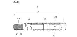
- FIG. 8 shows an example of a metal oil well pipe in which the pin includes a male threaded portion and does not include a pin seal surface and a pin shoulder surface, and the box includes a female threaded portion and does not include a box seal surface and a box shoulder surface. It is a diagram.
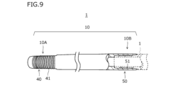
- FIG. 9 is a configuration diagram of an integral type oil well metal pipe according to the present embodiment. 10 is an enlarged view of the pin contact surface shown in FIG. 6; FIG. 11 is an enlarged view of the box contact surface shown in FIG. 7; FIG.
- the inventors studied a metal oil well pipe that can be fastened with a higher torque than before, and that can be applied to an oil well pipe connection used for horizontal drilling. As a result, the following findings were obtained.
- the oil country tubular goods connected body is formed by screwing together the threaded joints of the oil country tubular goods.
- the torque increases according to the number of revolutions. Especially in the final stage of screw tightening, the torque rises sharply.
- the screw tightening torque is too high, the oil well metal pipe may yield.
- the torque at which the oil well metal pipe yields when screwed is also referred to as "yield torque".
- yield torque the higher the yield torque, the higher the torque that can be applied to the oil well metal pipe. In other words, the yield torque can be used as an indicator of whether or not the oil well metal pipe can be fastened with a high torque.
- FIG. 1 is a diagram showing the relationship between the coefficient of friction of a resin coating and the yield torque.
- the horizontal axis of FIG. 1 indicates the coefficient of friction ( ⁇ ) of the resin coating.
- the vertical axis in FIG. 1 indicates the yield torque (ft.lbs) when the oil well metal pipe having the resin film formed thereon is screwed.
- the correlation coefficient R2 between the coefficient of friction of the resin coating and the yield torque was 0.144. From these results, almost no positive correlation is observed between the coefficient of friction of the resin coating and the yield torque. That is, contrary to the expectations of the inventors, it has become clear that the correlation between the friction coefficient and the yield torque is weak. In short, as a result of investigations by the present inventors, it has become clear that simply increasing the friction coefficient of the resin coating does not effectively increase the yield torque.
- the inventors conducted further studies on metal pipes for oil wells that can be fastened with high torque.
- the inventors paid attention to the behavior of the resin coating in the final stage of screw tightening.
- the resin films come into contact with each other with high surface pressure and slide.
- the inventors thought that the resin coating might receive a slipping force (shear force) from the pin contact surface and the box contact surface. If the resin coating receives a shear force exceeding the shear strength of the resin coating, the resin coating will be destroyed. As a result, the oil well metal pipe may be prone to yield.
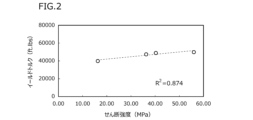
- FIG. 2 is a diagram showing the relationship between the shear strength of a resin coating and the yield torque.
- the horizontal axis of FIG. 2 indicates the shear strength (MPa) of the resin coating.
- the vertical axis in FIG. 2 indicates the yield torque (ft.lbs) when screwing the oil well metal pipe on which the resin coating is formed.
- the correlation coefficient R2 between the shear strength of the resin coating and the yield torque was 0.874. From this result, a strong positive correlation is recognized between the shear strength of the resin coating and the yield torque. In other words, as a result of detailed studies by the present inventors, it has become clear that the yield torque of the oil well metal pipe can be effectively increased by increasing the shear strength of the resin coating.
- the present inventors investigated a method for increasing the shear strength of the resin coating. As a result, it became clear that the shear strength of the resin coating could be increased by including solid powder of hydrated magnesium silicate and/or TiO 2 . Therefore, the present inventors investigated in detail the shear strength of a resin coating containing hydrous magnesium silicate powder and/or TiO 2 .
- the present inventors focused on the components in the resin film and investigated means for increasing the shear strength.
- resin 50.0 to 99.5% by mass
- wax 0 to 10.0% by mass
- fluorine additive 0 to 30.0% by mass
- graphite 0 to 10.0% by mass
- rust prevention Pigment 0 to 30.0% by mass
- coloring pigment 0 to 10.0% by mass
- coupling agent 0 to 10.0% by mass
- hydrated magnesium silicate powder 1.5 to 50 0% by mass
- TiO 2 0.5 to 30.0% by mass.
- FIG. 3 is a diagram showing the relationship between F1 in the resin coating and the shear strength of the resin coating.
- FIG. 3 is a partial excerpt of the results of the examples described later.
- the horizontal axis of FIG. 3 indicates F1.
- the vertical axis in FIG. 3 indicates the shear strength (MPa) of the resin coating. Referring to FIG. 3, when F1 is 5.00 or less, the shear strength of the resin coating is 36.00 MPa or more. The reason for this is not clarified in detail, but the inventors presume as follows.
- the hydrated magnesium silicate is particles having high shear strength in the crystals.
- TiO 2 is a hard particle in the resin coating with the above composition. If the resin coating contains a large amount of these components, when the resin coating is subjected to a shearing force, the particles themselves will resist the shearing force, thereby suppressing the shear failure of the resin coating. That is, it is considered that the shear strength of the resin coating increases as the contents of the hydrous magnesium silicate powder and TiO 2 increase. On the other hand, wax, fluorine-based additives, and graphite lower the hardness of the resin coating.
- the shear strength of the resin film decreases as the content of wax, fluorine-based additive, and graphite increases. Therefore, the present inventors believe that the shear strength can be increased by reducing the ratio of the total content of wax, fluorine-based additive, and graphite to the total content of hydrous magnesium silicate powder and TiO2 . is guessing.
- An oil well metal pipe a tube body including a first end and a second end;
- the pipe body is a pin formed at the first end; a box formed at the second end;
- the pin is including a pin contact surface including an externally threaded portion;
- the box is including a box contact surface including an internal thread;
- the oil well metal pipe further comprises: a resin coating on or above at least one of the pin contact surface and the box contact surface;
- the resin coating is Resin: 50.0 to 99.5% by mass, Wax: 0 to 10.0% by mass, Fluorine-based additive: 0 to 30.0% by mass, Graphite: 0 to 10.0% by mass, Antirust pigment: 0 to 30.0% by mass, Coloring pigment: 0 to 10.0% by mass, and Coupling agent: 0 to 10.0% by mass, Hydrous magnesium silicate powder: 1.5 to 50.0% by mass, and TiO 2 : containing one or two selected from the group consisting of 0.5 to 30.0% by mass, satisfying formula (1), Metal
- W is the content of wax in mass%
- F is the content of fluorine-based additive in mass%
- G is the content of graphite in mass%
- M is the content of the hydrated magnesium silicate powder in mass %
- T is the content of TiO 2 in mass %.
- the metal pipe for oil well according to [1],
- the resin is One or two selected from the group consisting of epoxy resins and urethane resins, Metal pipe for oil wells.
- the pin contact surface further includes a pin seal surface and a pin shoulder surface
- the box contact surface further includes a box seal surface and a box shoulder surface
- Metal pipe for oil wells
- Oil well metal pipes have a well-known configuration.
- Oil well metal pipes include T&C type oil well metal pipes and integral type oil well metal pipes. Each type of oil well metal pipe will be described in detail below.
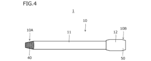
- FIG. 4 is a configuration diagram showing an example of the oil well metal pipe 1 according to this embodiment.
- FIG. 4 is a configuration diagram of a so-called T&C type (Threaded and Coupled) oil well metal pipe 1 .
- oil well metal pipe 1 includes pipe body 10 .
- the pipe body 10 extends in the pipe axial direction.
- a cross section of the pipe body 10 perpendicular to the pipe axis direction is circular.
- the tube body 10 includes a first end 10A and a second end 10B.
- the first end 10A is the end opposite to the second end 10B.
- a coupling 12 is attached to one end of the pin tube body 11 . More specifically, the coupling 12 is screwed to one end of the pin tube 11 .
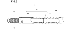
- FIG. 5 is a partial cross-sectional view showing a cross section (longitudinal cross section) parallel to the tube axis direction of the coupling 12 of the oil well metal pipe 1 shown in FIG. 4 and 5, tube body 10 includes pin 40 and box 50. As shown in FIG. The pin 40 is formed on the first end portion 10A of the tube body 10 . When fastening, the pin 40 is inserted into the box 50 of another oil well metal pipe 1 (not shown) and fastened to the box 50 of the other oil well metal pipe 1 by screws.
- the box 50 is formed at the second end 10B of the pipe body 10. At the time of fastening, the pin 40 of the other oil well metal pipe 1 is inserted into the box 50 and is fastened with the pin 40 of the other oil well metal pipe 1 by screws.
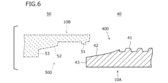
- FIG. 6 is a cross-sectional view parallel to the pipe axis direction of the oil well metal pipe 1 of the portion near the pin 40 of the oil well metal pipe 1 shown in FIG.
- a broken line portion in FIG. 6 shows the configuration of the box 50 of another oil well metal pipe 1 when fastening with another oil well metal pipe 1 .
- the pin 40 has a pin contact surface 400 on the outer peripheral surface of the first end 10A of the pipe body 10. As shown in FIG. The pin contact surface 400 is screwed into the box 50 of the other oil well metal pipe 1 and comes into contact with the box contact surface 500 (described later) of the box 50 when fastening with the other oil well metal pipe 1 .
- the pin contact surface 400 includes at least a male threaded portion 41 formed on the outer peripheral surface of the first end portion 10A.
- Pin contact surface 400 may further include pin seal surface 42 and pin shoulder surface 43 .
- the pin shoulder surface 43 is arranged on the distal end surface of the first end portion 10A, and the pin seal surface 42 is located closer to the distal end side of the first end portion 10A than the male thread portion 41 on the outer peripheral surface of the first end portion 10A. are placed. That is, the pin seal surface 42 is arranged between the male threaded portion 41 and the pin shoulder surface 43 .
- the pin seal surface 42 is provided in a tapered shape. Specifically, the outer diameter of the pin seal surface 42 gradually decreases from the male threaded portion 41 toward the pin shoulder surface 43 in the longitudinal direction (pipe axis direction) of the first end portion 10A.
- the pin seal surface 42 contacts the box seal surface 52 (described later) of the box 50 of the other oil well metal pipe 1 . More specifically, when the pin 40 is inserted into the box 50 of the other metal pipe 1 for oil wells, the pin seal surface 42 comes into contact with the box seal surface 52 . By further screwing the pin 40 into the box 50 of the other oil well metal pipe 1 , the pin seal surface 42 is brought into close contact with the box seal surface 52 . As a result, during fastening, the pin seal surface 42 is in close contact with the box seal surface 52 to form a seal based on metal-to-metal contact. Therefore, the airtightness can be improved in the metal pipes 1 for oil wells that are fastened to each other.
- the pin shoulder surface 43 is arranged on the tip surface of the first end portion 10A. That is, in the pin 40 shown in FIG. 6, the male threaded portion 41, the pin seal surface 42, and the pin shoulder surface 43 are arranged in order from the center of the pipe body 10 toward the first end portion 10A.
- the pin shoulder surface 43 faces and comes into contact with the box shoulder surface 53 (described later) of the box 50 of the other oil well metal pipe 1 . More specifically, when the pin 40 is inserted into the box 50 of the other oil well metal pipe 1 , the pin shoulder surface 43 comes into contact with the box shoulder surface 53 during fastening. Thereby, high torque can be obtained at the time of fastening. Also, the positional relationship between the pin 40 and the box 50 in the fastened state can be stabilized.
- pin contact surface 400 of the pin 40 includes at least the male threaded portion 41 . That is, pin contact surface 400 may include external threads 41 and not include pin seal surface 42 and pin shoulder surface 43 . Pin contact surface 400 includes external threads 41 and pin shoulder surface 43 and may not include pin seal surface 42 . Pin contact surface 400 may include external threads 41 and pin seal surface 42 and may not include pin shoulder surface 43 .
- FIG. 7 is a cross-sectional view parallel to the pipe axis direction of the oil well metal pipe 1 of the box 50 vicinity portion of the oil well metal pipe 1 shown in FIG.
- a broken line portion in FIG. 7 shows the configuration of the pin 40 of another oil well metal pipe 1 when fastening with another oil well metal pipe 1 .
- box 50 has a box contact surface 500 on the inner peripheral surface of second end 10B of tube body 10 .
- the pin 40 of the other oil well metal pipe 1 is screwed into the box contact surface 500 and contacts the pin contact surface 400 of the pin 40 when the box contact surface 500 is fastened with the other oil well metal pipe 1 .
- the box contact surface 500 includes at least a female threaded portion 51 formed on the inner peripheral surface of the second end portion 10B. At the time of fastening, the female threaded portion 51 meshes with the male threaded portion 41 of the pin 40 of the other oil well metal pipe 1 .
- the box contact surface 500 may further include a box sealing surface 52 and a box shoulder surface 53.
- the box seal surface 52 is arranged closer to the pipe main body 10 than the female threaded portion 51 on the inner peripheral surface of the second end portion 10B. That is, the box seal surface 52 is arranged between the female threaded portion 51 and the box shoulder surface 53 .
- the box seal surface 52 is tapered. Specifically, in the box seal surface 52, the inner diameter gradually decreases from the female threaded portion 51 toward the box shoulder surface 53 in the longitudinal direction (pipe axis direction) of the second end portion 10B.
- the box seal surface 52 When fastening with another oil well metal pipe 1 , the box seal surface 52 contacts the pin seal surface 42 of the pin 40 of the other oil well metal pipe 1 . More specifically, when the pin 40 of the other oil well metal pipe 1 is screwed into the box 50 at the time of fastening, the box seal surface 52 comes into contact with the pin seal surface 42, and further screwing causes the box seal surface 52 is in close contact with the pin seal surface 42 . As a result, during fastening, the box seal surface 52 is in close contact with the pin seal surface 42 to form a seal based on metal-to-metal contact. Therefore, the airtightness can be improved in the metal pipes 1 for oil wells that are fastened to each other.
- the box shoulder surface 53 is arranged closer to the pipe main body 10 than the box seal surface 52 is. That is, in the box 50, the box shoulder surface 53, the box seal surface 52, and the internal thread portion 51 are arranged in this order from the center of the pipe body 10 toward the tip of the second end portion 10B.
- the box shoulder surface 53 faces and contacts the pin shoulder surface 43 of the pin 40 of the other oil well metal pipe 1 . More specifically, when fastening, the box shoulder surface 53 contacts the pin shoulder surface 43 by inserting the pin 40 of the other oil well metal pipe 1 into the box 50 . Thereby, high torque can be obtained at the time of fastening. Also, the positional relationship between the pin 40 and the box 50 in the fastened state can be stabilized.
- the box contact surface 500 includes at least the female threaded portion 51 .
- the female threaded portion 51 of the box contact surface 500 of the box 50 corresponds to the male threaded portion 41 of the pin contact surface 400 of the pin 40 and contacts the male threaded portion 41 .
- Box seal surface 52 corresponds to pin seal surface 42 and contacts pin seal surface 42 .
- Box shoulder surface 53 corresponds to pin shoulder surface 43 and contacts pin shoulder surface 43 .
- the box contact surface 500 includes the female threaded portion 51 and does not include the box seal surface 52 and the box shoulder surface 53. If pin contact surface 400 includes external threads 41 and pin shoulder surface 43 but does not include pin seal surface 42 , box contact surface 500 includes internal threads 51 and box shoulder surface 53 but does not include box seal surface 52 . If pin contact surface 400 includes male threads 41 and pin seal surface 42 but does not include pin shoulder surface 43 , box contact surface 500 includes female threads 51 and box seal surface 52 but does not include box shoulder surface 53 .
- the pin contact surface 400 may include multiple external threads 41 , multiple pin seal surfaces 42 , or multiple pin shoulder surfaces 43 .
- the pin shoulder surface 43, the pin seal surface 42, the male threaded portion 41, the pin seal surface 42, the pin shoulder surface 43, the pin seal surface from the tip of the first end portion 10A toward the center of the pipe body 10. 42 and the male threaded portion 41 may be arranged in this order.
- the box contact surface 500 of the box 50 from the tip of the second end portion 10B toward the center of the pipe body 10, the female threaded portion 51, the box sealing surface 52, the box shoulder surface 53, the box sealing surface 52, the female threaded portion. 51 , box sealing surface 52 , and box shoulder surface 53 .
- the pin 40 includes a male threaded portion 41, a pin seal surface 42 and a pin shoulder surface 43
- the box 50 includes a female threaded portion 51, a box seal surface 52 and a box shoulder surface 53.
- pin 40 may include external threads 41 and not include pin seal surface 42 and pin shoulder surface 43
- box 50 includes internal threads 51 and does not include box seal surface 52 and box shoulder surface 53
- FIG. 8 shows that pin 40 includes male threaded portion 41 and does not include pin seal surface 42 and pin shoulder surface 43
- box 50 includes female threaded portion 51 and does not include box seal surface 52 and box shoulder surface 53. It is a figure which shows an example of the metal pipe 1 for oil wells.
- the oil well metal pipe 1 shown in FIGS. 4, 5 and 8 is a so-called T&C type oil well metal pipe 1 in which a pipe body 10 includes a pin pipe body 11 and a coupling 12 .
- the oil well metal pipe 1 of the present embodiment may be of the integral type instead of the T&C type.
- FIG. 9 is a configuration diagram of an integral type oil well metal pipe 1 according to this embodiment.
- an integral type oil well metal pipe 1 includes a pipe body 10 .
- the tube body 10 includes a first end 10A and a second end 10B.
- the first end 10A is arranged opposite to the second end 10B.
- the pipe body 10 includes the pin pipe body 11 and the coupling 12 . That is, in the T&C type oil well metal pipe 1, the pipe body 10 is configured by fastening two separate members (the pin pipe body 11 and the coupling 12).
- the pipe main body 10 is integrally formed.
- the pin 40 is formed on the first end portion 10A of the pipe body 10. At the time of fastening, the pin 40 is inserted and screwed into the box 50 of the other integral type oil well metal pipe 1 and fastened to the box 50 of the other integral type oil well metal pipe 1 .
- a box 50 is formed at the second end 10B of the tube body 10 . At the time of fastening, the pin 40 of the other integral type oil well metal pipe 1 is inserted and screwed into the box 50 to be fastened with the pin 40 of the other integral type oil well metal pipe 1 .
- the configuration of the pin 40 of the integral type oil well metal tube 1 is the same as the configuration of the pin 40 of the T&C type oil well metal tube 1 shown in FIG.
- the configuration of the box 50 of the integral type oil well metal pipe 1 is the same as the configuration of the box 50 of the T&C type oil well metal pipe 1 shown in FIG. 6 and 7, in the pin 40, the pin shoulder surface 43, the pin seal surface 42, and the male screw portion 41 are arranged in this order from the tip of the first end portion 10A toward the center of the pipe body 10.
- the female screw portion 51, the box seal surface 52, and the box shoulder surface 53 are arranged in this order.
- the pin contact surface 400 of the pin 40 of the integral type oil well metal tube 1 should include at least the male threaded portion 41. good.
- the box contact surface 500 of the box 50 of the integral type oil well metal pipe 1 should include at least the female screw portion 51. good.
- the oil well metal pipe 1 of this embodiment may be of the T&C type or the integral type.
- the oil well metal pipe 1 of this embodiment has a resin coating 100 on or above at least one of the pin contact surface 400 and the box contact surface 500 .
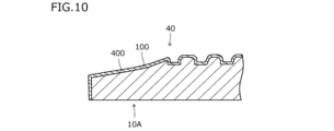
- FIG. 10 is an enlarged view of pin contact surface 400 shown in FIG.
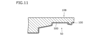
- FIG. 11 is an enlarged view of the box contact surface 500 shown in FIG.
- the oil well metal pipe 1 according to this embodiment may have a resin coating 100 on both the pin contact surface 400 and the box contact surface 500 .
- the oil well metal pipe 1 according to this embodiment may be provided with the resin coating 100 only on either the pin contact surface 400 or the box contact surface 500 . For example, as shown in FIG.
- the oil well metal pipe 1 has the resin coating 100 on the pin contact surface 400 and/or the box contact surface 500 .
- the resin coating 100 contains the following components.
- the resin contained in the resin coating 100 according to this embodiment is not particularly limited. However, it is considered that the resin coating 100 receives a shear force when the oil well metal pipe 1 is fastened. Therefore, in order to stably increase the yield torque of the oil well metal pipe 1 on which the resin coating 100 is formed, it is preferable to use a resin having an appropriate hardness.
- the resin in the resin film 100 according to the present embodiment includes epoxy resin, phenol resin, acrylic resin, urethane resin, polyester resin, polyamideimide resin, polyamide resin, polyimide resin, and polyether ether ketone resin.
- the resin in this embodiment is one or more selected from the group consisting of epoxy resins, urethane resins, polyimide resins, and phenol resins, and more preferably selected from the group consisting of epoxy resins and urethane resins. more preferably one of epoxy resin and urethane resin.
- the resin coating 100 may contain multiple types of resins. When a plurality of types of resins are contained, the resin content means the total content of the plurality of types of resins.
- Resin is the base material of the resin coating 100 .
- the base material means the component contained in the resin film 100 in the largest amount. If the content of the resin is too low, it becomes difficult to disperse the composition such as the hydrous magnesium silicate powder described later in the resin. As a result, the shear strength of the resin coating is lowered. On the other hand, if the content of the resin is too high, the hydrous magnesium silicate powder and/or other components including TiO 2 cannot be sufficiently contained. As a result, the shear strength of the resin coating 100 rather decreases. Therefore, the resin content is 50.0 to 99.5% by mass. A preferable lower limit of the resin content is 55.0% by mass, more preferably 60.0% by mass, and still more preferably 65.0% by mass. A preferable upper limit of the resin content is 97.0% by mass, more preferably 95.0% by mass, and still more preferably 90.0% by mass.
- the resin coating 100 contains one or two selected from the group consisting of hydrous magnesium silicate powder and TiO 2 . Specifically, it contains one or two selected from the group consisting of hydrated magnesium silicate powder: 1.5 to 50.0% by mass and TiO 2 : 0.5 to 30.0% by mass. All of these components increase the shear strength of the resin coating 100 .
- Hydrous magnesium silicate powder 1.5 to 50.0% by mass
- the hydrated magnesium silicate powder is a component that is optionally contained, and may not be contained. That is, the content of the hydrated magnesium silicate powder may be 0% by mass.
- the hydrated magnesium silicate powder increases the shear strength of the resin coating 100 .
- a hydrous magnesium silicate powder is a solid powder having a layered structure.
- the hydrous magnesium silicate powder also has high bonding strength between layers and high shear strength. In other words, the hydrous magnesium silicate powder is particles having high shear strength in the crystals.
- the hydrous magnesium silicate powder resists the shearing and suppresses the shear failure of the resin coating 100 .
- the hydrated magnesium silicate powder is considered to increase the shear strength of the resin coating 100 .
- the content of the hydrated magnesium silicate powder is 1.5 to 50.0% by mass.
- the preferable lower limit of the content of the hydrated magnesium silicate powder is 2.0% by mass, more preferably 4.0% by mass, still more preferably 7.0% by mass, still more preferably 10.0% by mass. be.
- a preferable upper limit of the content of the hydrated magnesium silicate powder is 45.0% by mass, more preferably 43.0% by mass, and still more preferably 40.0% by mass.
- TiO 2 0.5 to 30.0% by mass
- TiO 2 is an optional component and may not be included. That is, the content of TiO 2 may be 0% by mass.
- TiO 2 enhances the shear strength of the resin coating 100 .
- TiO2 is hard powder particles. Therefore, when the resin coating 100 receives a shearing force, the TiO 2 resists the shearing and suppresses the shear fracture of the resin coating 100 . Thus, TiO 2 is considered to increase the shear strength of the resin coating 100 .
- the content of TiO 2 is too high, it may promote abrasive wear and reduce the seizure resistance of the oil well metal pipe 1 .
- the content of TiO 2 is 0.5-30.0% by mass.
- the preferred lower limit of the content of TiO2 is 0.7% by mass, more preferably 1.0% by mass, more preferably 2.0% by mass, still more preferably 2.5% by mass, More preferably, it is 5.0% by mass.
- a preferable upper limit of the content of TiO 2 is 25.0% by mass, more preferably 20.0% by mass, further preferably 15.0% by mass.
- Wax 0 to 10.0% by mass
- the type of wax contained in the resin coating 100 according to this embodiment is not particularly limited.
- Waxes are, for example, one or more selected from the group consisting of animal waxes, vegetable waxes, mineral waxes and synthetic waxes.
- waxes include beeswax, spermaceti (or animal wax), Japan wax, carnauba wax, candelilla wax, rice wax (or vegetable wax), paraffin wax, microcrystalline wax, petrolatum, montan wax, One or more selected from the group consisting of ozokerite, ceresin (all minerals), oxidized wax, polyethylene wax, polypropylene wax, Fischer-Tropsch wax, amide wax, hardened castor oil (castor wax) (all synthetic waxes) is. More preferably, the wax is one or two selected from the group consisting of polyethylene wax and polypropylene wax.
- the resin coating 100 may contain multiple types of wax. When multiple types of wax are contained, the wax content means the total content of the multiple types of wax.
- wax is a component that is optionally contained, and may not be contained. That is, the wax content may be 0% by mass.
- the wax enhances the lubricity of the resin coating 100 .
- the wax content is 0 to 10.0% by mass.
- the lower limit of the wax content is preferably 0.1% by mass, more preferably 0.5% by mass, still more preferably 1.0% by mass, still more preferably 2.0% by mass.
- the upper limit of the wax content is preferably 9.0% by mass, more preferably 8.0% by mass, still more preferably 7.5% by mass.
- Fluorine-based additive 0 to 30.0% by mass
- fluorine-containing additives are also collectively referred to as fluorine-based additives.
- the fluorine-based additive is, for example, one or two selected from the group consisting of perfluoropolyether (PFPE) and polytetrafluoroethylene (PTFE).
- PFPE perfluoropolyether
- PTFE polytetrafluoroethylene
- the resin coating 100 may contain a plurality of types of fluorine-based additives. When a plurality of types of fluorine-based additives are contained, the content of fluorine-based additives means the total content of the plurality of types of fluorine-based additives.
- the fluorine-based additive is a component that is optionally contained, and may not be contained. That is, the content of the fluorine-based additive may be 0% by mass.
- the fluorine-based additive enhances the lubricity of the resin coating 100 . As long as the fluorine-based additive is contained even in a small amount, the above effects can be obtained to some extent.
- the content of the fluorine-based additive is too high, the hardness of the resin coating 100 is lowered. As a result, the shear strength of the resin coating 100 may decrease. Therefore, the content of the fluorine-based additive is 0 to 30.0% by mass.
- a preferred lower limit for the content of the fluorine-based additive is 1.0% by mass, more preferably 3.0% by mass, still more preferably 4.5% by mass, and still more preferably 7.5% by mass. be.
- a preferable upper limit of the content of the fluorine-based additive is 25.0% by mass, more preferably 20.0% by mass, still more preferably 15.0% by mass, still more preferably 12.5% by mass. be.
- graphite 0 to 10.0% by mass
- graphite is an optional component and may not be included. That is, the content of graphite may be 0% by mass.
- graphite enhances the lubricity of the resin coating 100 . The above effects can be obtained to some extent if even a small amount of graphite is contained.
- the content of graphite is 0 to 10.0% by mass.
- a preferable lower limit of the graphite content is 1.0% by mass, more preferably 2.0% by mass, and still more preferably 3.0% by mass.
- the upper limit of the graphite content is preferably 9.0% by mass, more preferably 8.0% by mass, still more preferably 7.0% by mass.
- Antirust pigment 0 to 30.0% by mass
- the rust preventive pigment is not particularly limited as long as it is a known pigment that enhances the rust preventiveness of the resin coating 100 .
- the antirust pigment is, for example, one or more selected from the group consisting of zinc phosphate, aluminum tripolyphosphate, aluminum phosphite, carboxylic acid metal soap, and sulfonate.
- the resin coating 100 may contain multiple types of antirust pigments. When a plurality of types of rust preventive pigments are contained, the content of the rust preventive pigments means the total content of the plurality of types of rust preventive pigments.
- the antirust pigment is an optional component and may not be included. That is, the content of the rust preventive pigment may be 0% by mass.
- the rust preventive pigment enhances the rust preventiveness of the resin coating 100 . If even a small amount of rust preventive pigment is contained, the above effect can be obtained to some extent. On the other hand, if the content of the rust preventive pigment is too high, the resin coating 100 will be poorly formed. Therefore, the content of the rust preventive pigment is 0 to 30.0% by mass.
- a preferable lower limit of the content of the rust preventive pigment is 1.0% by mass, more preferably 2.0% by mass, still more preferably 3.0% by mass, and still more preferably 4.0% by mass. .
- a preferable upper limit of the content of the rust preventive pigment is 25.0% by mass, more preferably 20.0% by mass, and still more preferably 10.0% by mass.
- the coloring pigment is not particularly limited as long as it is a known pigment capable of coloring the resin coating 100 .
- the coloring pigment is, for example, one or more selected from the group consisting of phthalocyanine copper, zinc oxide, yellow iron oxide, iron oxide, and chromium hydroxide.
- the resin coating 100 may contain multiple types of color pigments. When multiple types of color pigments are contained, the content of the color pigments means the total content of the multiple types of color pigments.
- the color pigment is a component that is arbitrarily contained and may not be contained. That is, the content of the coloring pigment may be 0% by mass.
- the coloring pigment colors the resin coating 100 .
- damage to the resin coating 100 becomes easier to visually recognize.
- the content of the coloring pigment is 0 to 10.0% by mass.
- a preferable lower limit of the content of the color pigment is 0.1% by mass, more preferably 0.2% by mass, and still more preferably 0.5% by mass.
- the upper limit of the content of the color pigment is preferably 8.0% by mass, more preferably 5.0% by mass, and still more preferably 3.0% by mass.
- the coupling agent is not particularly limited, but is, for example, one or two selected from the group consisting of silane coupling agents and titanium coupling agents.
- the resin coating 100 may contain multiple types of coupling agents. When multiple types of coupling agents are contained, the content of the coupling agents means the total content of the multiple types of coupling agents.
- the coupling agent is an optional component and may not be included. That is, the content of the coupling agent may be 0% by mass.
- the coupling agent enhances adhesion of the resin coating 100 . Therefore, when the oil well metal pipe 1 is repeatedly screwed and unscrewed, peeling of the resin coating 100 is suppressed. As long as the coupling agent is contained even in a small amount, the above effect can be obtained to some extent.
- the content of the coupling agent exceeds 10.0% by mass, the formation of the resin film 100 becomes defective. Therefore, the content of the coupling agent is 0 to 10.0% by mass.
- a preferable lower limit of the content of the coupling agent is 0.1% by mass, more preferably 0.2% by mass, and still more preferably 0.5% by mass.
- a preferable upper limit of the content of the coupling agent is 8.0% by mass, more preferably 6.0% by mass, further preferably 4.0% by mass.
- Other components 0 to 10.0% by mass
- other components are optional components and may not be included. That is, the content of other components may be 0% by mass.
- Other components are, for example, one or two selected from the group consisting of preservatives and antioxidants. When other components are contained, the total content of the other components is 10.0% by mass or less. That is, the total content of other components is 0 to 10.0% by mass.
- the resin film 100 contains resin: 50.0 to 99.5% by mass, wax: 0 to 10.0% by mass, fluorine-based additive: 0 to 30.0% by mass, graphite: 0 to 10.0% by mass, Antirust pigment: 0 to 30.0% by mass, coloring pigment: 0 to 10.0% by mass, coupling agent: 0 to 10.0% by mass, other components: 0 to 10.0% by mass, and water content
- the resin coating 100 may be one or two selected from the group consisting of magnesium silicate powder: 1.5 to 50.0% by mass and TiO 2 : 0.5 to 30.0% by mass. .
- the resin coating 100 satisfies the formula (1) on the premise that it contains the above components. (W+F+G)/(M+T) ⁇ 5.00 (1)
- W is the content of wax in mass%
- F is the content of fluorine-based additive in mass%
- G is the content of graphite in mass%
- M is the content of the hydrated magnesium silicate powder in mass %
- T is the content of TiO 2 in mass %.
- the shear strength of the resin coating 100 increases as the contents of the hydrous magnesium silicate powder and TiO 2 increase.
- the shear strength of the resin coating 100 decreases as the content of wax, fluorine-based additive, and graphite increases. Therefore, the shear strength of the resin coating 100 can be increased by reducing the ratio of the total content of wax, fluorine-based additive, and graphite to the total content of hydrous magnesium silicate powder and TiO 2 .
- the shear strength of the resin coating 100 having the components described above, it has been proved by examples described later that by setting F1 to 5.00 or less, the shear strength of the resin coating 100 can be increased to 36.00 MPa or more.
- F1 is set to 5.00 or less on the premise that the resin film 100 has the above components.
- a preferable upper limit of F1 is 4.90, more preferably 4.80, and still more preferably 4.70.
- the lower limit of F1 is not particularly limited, and may be 0.00.
- the shear strength of the resin film 100 is increased by containing the above components and satisfying the formula (1). As a result, the oil well metal pipe 1 provided with the resin coating 100 has an increased yield torque.
- shear strength of the resin coating 100 is not particularly limited, it is preferably as high as possible. If the shear strength of the resin coating 100 is 36.00 MPa or more, the yield torque of the oil well metal pipe 1 provided with the resin coating 100 can be significantly increased. Therefore, the shear strength of the resin coating 100 is preferably 36.00 MPa or more. A more preferable lower limit of the shear strength of the resin coating 100 is 36.50 MPa, more preferably 36.70 MPa, still more preferably 37.00 MPa. Although the upper limit of the shear strength of the resin coating 100 is not particularly limited, it is, for example, 70.00 MPa.
- the shear strength of the resin coating 100 can be measured by the following method.
- the shear strength of the test piece on which the resin coating 100 is formed is determined using a surface/interface property analyzer (manufactured by Daipla-Wintes Co., Ltd., trade name: SAICAS).
- SAICAS surface/interface property analyzer
- the resin coating 100 is a cold-rolled steel sheet (the chemical composition is C ⁇ 0.15%, Mn ⁇ 0.60%, P ⁇ 0.100%, S ⁇ 0.050%, and the balance: Fe and impurities).
- the target film thickness is set to 20 ⁇ m.
- the surface of the resin coating 100 is cut at an angle of 10° at a constant speed (horizontal speed 2 ⁇ m/sec, vertical speed 0.2 ⁇ m/sec), and the resin coating 100 is cooled. It is made to separate from the rolled steel plate. All tests are performed at room temperature. At this time, the shear strength (MPa) of the resin coating 100 can be obtained from the horizontal force, vertical force, and vertical displacement applied to the cutting edge.
- MPa shear strength
- the thickness of the resin coating 100 is not particularly limited.
- the thickness of the resin coating 100 is, for example, 1-100 ⁇ m. In this case, the yield torque of the oil well metal pipe 1 can be increased more stably.
- the lower limit of the thickness of the resin coating 100 is preferably 2 ⁇ m, more preferably 5 ⁇ m, and still more preferably 10 ⁇ m.
- the upper limit of the thickness of the resin coating 100 is preferably 50 ⁇ m, more preferably 40 ⁇ m, and even more preferably 30 ⁇ m.
- the thickness of the resin coating 100 can be measured by the following method.
- a probe of an electromagnetic induction type film thickness measuring device is brought into contact with the pin contact surface 400 or the box contact surface 500 on which the resin film 100 is formed.
- the probe has an electromagnet, and when a magnetic body is brought close to it, electromagnetic induction occurs, and the voltage changes depending on the distance between the probe and the magnetic body.
- the thickness of the resin coating 100 is obtained from the change in the amount of voltage.
- the measurement points are 12 points (0°, 30°, 60°, 90°, 120°, 150°, 180°, 210°, 240°, 270°, 300°, 12 points of 330°).
- the arithmetic average value of the measurement results at 12 points is taken as the thickness of the resin coating 100 .
- the chemical composition of the pipe main body 10 of the oil well metal pipe 1 according to this embodiment is not particularly limited. That is, in the present embodiment, the steel type of the pipe main body 10 of the oil well metal pipe 1 is not particularly limited.
- the pipe body 10 may be made of, for example, carbon steel, stainless steel, alloys, or the like. That is, the oil well metal pipe 1 may be a steel pipe made of an Fe-based alloy, or may be an alloy pipe represented by a Ni-based alloy pipe.
- the steel pipe is, for example, a low-alloy steel pipe, a martensitic stainless steel pipe, a duplex stainless steel pipe, or the like.
- Ni-based alloys and high alloy steels such as duplex stainless steels containing alloying elements such as Cr, Ni and Mo have high corrosion resistance. Therefore, if these high-alloy steels are used for the pipe body 10, excellent corrosion resistance can be obtained in corrosive environments containing hydrogen sulfide, carbon dioxide, and the like.
- the method for manufacturing the oil well metal pipe 1 includes a preparation process, a coating process, and a curing process.
- a curing step is performed after the coating step.
- an oil well metal pipe 1 is prepared that includes a pipe body 10 that includes a pin 40 that includes a pin contact surface 400 that includes a male threaded portion 41 and a box 50 that includes a box contact surface 500 that includes a female threaded portion 51 .
- the oil well metal pipe 1 according to this embodiment has a well-known configuration. That is, in the preparation step, the oil well metal pipe 1 having a well-known configuration may be prepared.
- the composition is applied to at least one of the pin contact surface 400 and the box contact surface 500 of the prepared oil well metal pipe 1 .
- the composition is a composition for forming the resin coating 100 described above.
- the composition contains resin: 50.0 to 99.5% by mass, wax: 0 to 10.0% by mass, fluorine-based additive: 0 to 30.0% by mass, graphite: 0 to 10.0% by mass, and Rust pigment: 0 to 30.0% by mass, coloring pigment: 0 to 10.0% by mass, and coupling agent: 0 to 10.0% by mass, hydrated magnesium silicate powder: 1.5 to 50.0% by mass.
- composition further contains a solvent.
- the composition excluding the solvent of the composition for forming the resin coating 100 is the same as the composition of the resin coating 100 described above.
- the composition can be produced, for example, by dissolving or dispersing the resin, hydrated magnesium silicate powder and/or TiO 2 and, if necessary, other components in a solvent and mixing them.
- the solvent is, for example, one or more selected from the group consisting of water, alcohol, and organic solvents.
- the solvent may contain trace amounts of surfactants.
- the ratio of the solvent is not particularly limited. The proportion of the solvent may be adjusted according to the coating method so that the composition has an appropriate viscosity.
- the ratio of the solvent is, for example, 40 to 60% by mass when the total of all components other than the solvent is 100% by mass.
- the method of applying the composition onto the pin contact surface 400 and/or the box contact surface 500 is not particularly limited, and any known method may be used.
- the composition in solution is applied onto the pin contact surface 400 and/or the box contact surface 500 by spraying.
- the composition is adjusted in viscosity so that it can be applied by spraying under an environment of normal temperature and normal pressure.
- the method of applying the composition onto the pin contact surface 400 and/or the box contact surface 500 may be brushing, dipping, or the like instead of spraying.
- the applied composition is cured to form the resin coating 100 .
- the composition is thermally cured to form a solid resin coating 100 .
- a heating method is not particularly limited, and a known method may be used.
- the heating method is, for example, a method in which the oil well metal pipe 1 coated with the composition is placed in a known heating furnace and heated.
- the heating temperature is, for example, 200-250° C., and the heating time is, for example, 5-30 minutes.
- the oil well metal pipe 1 according to the present embodiment is manufactured.
- the method for manufacturing the oil well metal pipe 1 according to the present embodiment may include other steps.
- the method for manufacturing the oil well metal pipe 1 according to the present embodiment may further include a surface treatment step before the coating step.
- a surface treatment step for example, one or more selected from the group consisting of pickling treatment, blasting treatment and alkali degreasing treatment is carried out.
- the pin contact surfaces 400 and/or the box contact surfaces 500 are immersed in a strong acid solution such as sulfuric acid, hydrochloric acid, nitric acid, hydrofluoric acid, or a mixed acid of these to remove the pin contact surfaces 400. and/or increase the surface roughness of the box contact surface 500;
- a strong acid solution such as sulfuric acid, hydrochloric acid, nitric acid, hydrofluoric acid, or a mixed acid of these to remove the pin contact surfaces 400. and/or increase the surface roughness of the box contact surface 500;
- blasting for example, sandblasting is performed by mixing a blasting material (abrasive) and compressed air and projecting it onto the pin contact surface 400 and/or the box contact surface 500 . In this case, the surface roughness of the pin contact surface 400 and/or the box contact surface 500 is increased.
- the pin contact surface 400 and the box contact surface 500 may be subjected to the same treatment or different treatments. Also, the priming process may be performed only on the pin contact surfaces 400 or only on the box contact surfaces 500 .
- the oil well metal pipe 1 according to the present embodiment is manufactured.
- the manufacturing method described above is an example of the manufacturing method of the oil well metal pipe 1 according to the present embodiment, and is not limited to this manufacturing method.
- the oil well metal pipe 1 according to this embodiment may be manufactured by other methods.
- the effects of the metal pipe for oil wells of this embodiment will be described more specifically by way of examples.
- the conditions in the following examples are examples of conditions adopted for confirming the feasibility and effect of the metal pipe for oil wells of this embodiment. Therefore, the oil well metal pipe of the present embodiment is not limited to this one condition example.
- a composition for forming a resin film was prepared and the shear strength of the resin film was evaluated. Specifically, it is as follows.
- Table 1 shows each component (% by mass) of the composition of each test number and F1 obtained from each component and formula (1).
- the composition contained a solvent other than the composition described in Table 1.
- a mixed solution of water, alcohol and surfactant was used as the solvent.
- the prepared composition was applied to a cold-rolled steel sheet (chemical composition: C ⁇ 0.15%, Mn ⁇ 0.60%, P ⁇ 0.100%, S ⁇ 0.050%, the balance: Fe and impurities). painted the object.
- the target film thickness was set to 20 ⁇ m.
- the cold-rolled steel sheet coated with the composition was heated in a heating furnace at 200-250° C. for 5-30 minutes to form a resin coating.
- the shear strength was measured for the cold-rolled steel sheets of each test number on which the resin coating was formed. Shear strength was measured by the method described above. Table 1 shows the obtained shear strength (MPa) of each test number.
- the resin coatings of test numbers 23 and 24 contained neither hydrous magnesium silicate powder nor TiO2 . As a result, these resin coatings had a shear strength of less than 36.00 MPa and did not have high shear strength.
- test numbers 25 to 28 did not satisfy formula (1), although the content of each component was appropriate. As a result, these resin coatings had a shear strength of less than 36.00 MPa and did not have high shear strength.
- test numbers 29 and 30 had too low a resin content. As a result, these resin coatings had a shear strength of less than 36.00 MPa and did not have high shear strength.
Landscapes
- Engineering & Computer Science (AREA)
- Chemical & Material Sciences (AREA)
- General Engineering & Computer Science (AREA)
- Mechanical Engineering (AREA)
- Chemical Kinetics & Catalysis (AREA)
- Materials Engineering (AREA)
- Metallurgy (AREA)
- Organic Chemistry (AREA)
- Paints Or Removers (AREA)
- Non-Disconnectible Joints And Screw-Threaded Joints (AREA)
- Lubricants (AREA)
- Laminated Bodies (AREA)
Abstract
Priority Applications (3)
| Application Number | Priority Date | Filing Date | Title |
|---|---|---|---|
| CN202280068949.8A CN118103628A (zh) | 2021-10-15 | 2022-10-13 | 油井用金属管 |
| AU2022364506A AU2022364506A1 (en) | 2021-10-15 | 2022-10-13 | Oil-Well Metal Pipe |
| CA3232798A CA3232798A1 (fr) | 2021-10-15 | 2022-10-13 | Tuyau metallique pour puits de petrole |
Applications Claiming Priority (2)
| Application Number | Priority Date | Filing Date | Title |
|---|---|---|---|
| JP2021169258 | 2021-10-15 | ||
| JP2021-169258 | 2021-10-15 |
Publications (1)
| Publication Number | Publication Date |
|---|---|
| WO2023063385A1 true WO2023063385A1 (fr) | 2023-04-20 |
Family
ID=85988701
Family Applications (1)
| Application Number | Title | Priority Date | Filing Date |
|---|---|---|---|
| PCT/JP2022/038194 WO2023063385A1 (fr) | 2021-10-15 | 2022-10-13 | Tuyau métallique pour puits de pétrole |
Country Status (5)
| Country | Link |
|---|---|
| CN (1) | CN118103628A (fr) |
| AR (1) | AR127340A1 (fr) |
| AU (1) | AU2022364506A1 (fr) |
| CA (1) | CA3232798A1 (fr) |
| WO (1) | WO2023063385A1 (fr) |
Citations (6)
| Publication number | Priority date | Publication date | Assignee | Title |
|---|---|---|---|---|
| JP2003021278A (ja) | 2001-04-11 | 2003-01-24 | Sumitomo Metal Ind Ltd | 鋼管用ねじ継手 |
| WO2006104251A1 (fr) | 2005-03-29 | 2006-10-05 | Sumitomo Metal Industries, Ltd. | Raccord fileté pour des tuyaux en acier |
| JP2010511135A (ja) * | 2006-12-01 | 2010-04-08 | テナリス・コネクシヨンズ・アクチエンゲゼルシヤフト | ねじ込み連結部用のナノ複合コーティング |
| CN103270146A (zh) * | 2010-07-20 | 2013-08-28 | 特纳瑞斯连接有限责任公司 | 具有改进的密封性、润滑性和耐腐蚀性的接头 |
| WO2015141159A1 (fr) * | 2014-03-20 | 2015-09-24 | 新日鐵住金株式会社 | Composition de revêtement lubrifiant solide, joint fileté pour tuyaux comprenant un revêtement lubrifiant solide formé à l'aide de ladite composition, et procédé de production dudit joint fileté pour tuyaux |
| WO2018216416A1 (fr) * | 2017-05-22 | 2018-11-29 | 新日鐵住金株式会社 | Joint fileté pour tuyau et procédé de fabrication d'un joint fileté pour tuyau |
-
2022
- 2022-10-12 AR ARP220102773A patent/AR127340A1/es unknown
- 2022-10-13 CA CA3232798A patent/CA3232798A1/fr active Pending
- 2022-10-13 CN CN202280068949.8A patent/CN118103628A/zh active Pending
- 2022-10-13 AU AU2022364506A patent/AU2022364506A1/en active Pending
- 2022-10-13 WO PCT/JP2022/038194 patent/WO2023063385A1/fr active Application Filing
Patent Citations (6)
| Publication number | Priority date | Publication date | Assignee | Title |
|---|---|---|---|---|
| JP2003021278A (ja) | 2001-04-11 | 2003-01-24 | Sumitomo Metal Ind Ltd | 鋼管用ねじ継手 |
| WO2006104251A1 (fr) | 2005-03-29 | 2006-10-05 | Sumitomo Metal Industries, Ltd. | Raccord fileté pour des tuyaux en acier |
| JP2010511135A (ja) * | 2006-12-01 | 2010-04-08 | テナリス・コネクシヨンズ・アクチエンゲゼルシヤフト | ねじ込み連結部用のナノ複合コーティング |
| CN103270146A (zh) * | 2010-07-20 | 2013-08-28 | 特纳瑞斯连接有限责任公司 | 具有改进的密封性、润滑性和耐腐蚀性的接头 |
| WO2015141159A1 (fr) * | 2014-03-20 | 2015-09-24 | 新日鐵住金株式会社 | Composition de revêtement lubrifiant solide, joint fileté pour tuyaux comprenant un revêtement lubrifiant solide formé à l'aide de ladite composition, et procédé de production dudit joint fileté pour tuyaux |
| WO2018216416A1 (fr) * | 2017-05-22 | 2018-11-29 | 新日鐵住金株式会社 | Joint fileté pour tuyau et procédé de fabrication d'un joint fileté pour tuyau |
Also Published As
| Publication number | Publication date |
|---|---|
| CN118103628A (zh) | 2024-05-28 |
| AR127340A1 (es) | 2024-01-10 |
| CA3232798A1 (fr) | 2023-04-20 |
| AU2022364506A1 (en) | 2024-05-02 |
Similar Documents
| Publication | Publication Date | Title |
|---|---|---|
| CN110651148B (zh) | 管用螺纹接头及管用螺纹接头的制造方法 | |
| WO2018216497A1 (fr) | Raccord fileté pour tuyau et procédé de production d'un raccord fileté pour tuyau | |
| EP2852785B1 (fr) | Jonction filetée tubulaire avec des propriétés améliorées d'assemblage avec un couple élevé | |
| JP5984945B2 (ja) | 固体被膜形成用組成物及び管状ねじ継手 | |
| JP5998278B2 (ja) | 固体潤滑被膜用組成物、その組成物から形成された固体潤滑被膜を備えた管用ねじ継手、及び、その管用ねじ継手の製造方法 | |
| WO2022045209A1 (fr) | Tuyau métallique pour puits de pétrole | |
| WO2018003455A1 (fr) | Raccord à vis destiné à un tuyau et procédé de fabrication de raccord à vis destiné à un tuyau | |
| JP2023164546A (ja) | 組成物、及び、その組成物からなる潤滑被膜層を備える管用ねじ継手 | |
| WO2020149310A1 (fr) | Joint fileté pour tuyaux et procédé de production d'un joint fileté pour tuyaux | |
| WO2023063385A1 (fr) | Tuyau métallique pour puits de pétrole | |
| JP6872032B2 (ja) | 組成物、及び、その組成物から形成された潤滑被膜層を備えた管用ねじ継手 | |
| WO2023063384A1 (fr) | Tuyau métallique pour puits de pétrole | |
| WO2024019019A1 (fr) | Tube métallique pour puits de pétrole | |
| WO2022039131A1 (fr) | Tuyau métallique pour puits de pétrole et procédé de fabrication d'un tuyau métallique pour puits de pétrole | |
| WO2020021691A1 (fr) | Raccord vissé pour tube et procédé de fabrication d'un raccord vissé pour tube | |
| CN118119785A (zh) | 油井用金属管 | |
| WO2023153274A1 (fr) | Tuyau métallique pour puits de pétrole | |
| WO2024005167A1 (fr) | Tube métallique pour puits de pétrole | |
| EA045795B1 (ru) | Металлическая труба для нефтяной скважины и способ ее изготовления |
Legal Events
| Date | Code | Title | Description |
|---|---|---|---|
| 121 | Ep: the epo has been informed by wipo that ep was designated in this application |
Ref document number: 22881080 Country of ref document: EP Kind code of ref document: A1 |
|
| WWE | Wipo information: entry into national phase |
Ref document number: 3232798 Country of ref document: CA |
|
| REG | Reference to national code |
Ref country code: BR Ref legal event code: B01A Ref document number: 112024005910 Country of ref document: BR |
|
| ENP | Entry into the national phase |
Ref document number: 2023554610 Country of ref document: JP Kind code of ref document: A |
|
| WWE | Wipo information: entry into national phase |
Ref document number: 2401002258 Country of ref document: TH |
|
| WWE | Wipo information: entry into national phase |
Ref document number: 0024000029 Country of ref document: IQ |
|
| WWE | Wipo information: entry into national phase |
Ref document number: AU2022364506 Country of ref document: AU |
|
| ENP | Entry into the national phase |
Ref document number: 2022364506 Country of ref document: AU Date of ref document: 20221013 Kind code of ref document: A |
|
| WWE | Wipo information: entry into national phase |
Ref document number: 2022881080 Country of ref document: EP |
|
| ENP | Entry into the national phase |
Ref document number: 2022881080 Country of ref document: EP Effective date: 20240515 |