WO2022255169A1 - Agent chimique, tuyau de puits de pétrole et joint à vis pour tuyau de puits de pétrole - Google Patents
Agent chimique, tuyau de puits de pétrole et joint à vis pour tuyau de puits de pétrole Download PDFInfo
- Publication number
- WO2022255169A1 WO2022255169A1 PCT/JP2022/021281 JP2022021281W WO2022255169A1 WO 2022255169 A1 WO2022255169 A1 WO 2022255169A1 JP 2022021281 W JP2022021281 W JP 2022021281W WO 2022255169 A1 WO2022255169 A1 WO 2022255169A1
- Authority
- WO
- WIPO (PCT)
- Prior art keywords
- weight
- lubricating coating
- solid
- binder resin
- tightening
- Prior art date
Links
- 239000003129 oil well Substances 0.000 title claims abstract description 14
- 239000013043 chemical agent Substances 0.000 title abstract description 3
- 239000007787 solid Substances 0.000 claims abstract description 276
- 238000000576 coating method Methods 0.000 claims abstract description 186
- 239000011248 coating agent Substances 0.000 claims abstract description 174
- 229920005989 resin Polymers 0.000 claims abstract description 102
- 239000011347 resin Substances 0.000 claims abstract description 102
- 239000011230 binding agent Substances 0.000 claims abstract description 98
- 239000000314 lubricant Substances 0.000 claims abstract description 98
- 239000000020 Nitrocellulose Substances 0.000 claims abstract description 69
- 229920001220 nitrocellulos Polymers 0.000 claims abstract description 69
- ZQKXQUJXLSSJCH-UHFFFAOYSA-N melamine cyanurate Chemical group NC1=NC(N)=NC(N)=N1.O=C1NC(=O)NC(=O)N1 ZQKXQUJXLSSJCH-UHFFFAOYSA-N 0.000 claims abstract description 68
- 229920000180 alkyd Polymers 0.000 claims abstract description 66
- 239000002245 particle Substances 0.000 claims abstract description 20
- 230000001050 lubricating effect Effects 0.000 claims description 218
- 239000003921 oil Substances 0.000 claims description 81
- 150000001875 compounds Chemical class 0.000 claims description 33
- 239000000463 material Substances 0.000 claims description 29
- 239000002904 solvent Substances 0.000 claims description 22
- NIQCNGHVCWTJSM-UHFFFAOYSA-N Dimethyl phthalate Chemical compound COC(=O)C1=CC=CC=C1C(=O)OC NIQCNGHVCWTJSM-UHFFFAOYSA-N 0.000 claims description 16
- DOIRQSBPFJWKBE-UHFFFAOYSA-N dibutyl phthalate Chemical compound CCCCOC(=O)C1=CC=CC=C1C(=O)OCCCC DOIRQSBPFJWKBE-UHFFFAOYSA-N 0.000 claims description 16
- FLKPEMZONWLCSK-UHFFFAOYSA-N diethyl phthalate Chemical compound CCOC(=O)C1=CC=CC=C1C(=O)OCC FLKPEMZONWLCSK-UHFFFAOYSA-N 0.000 claims description 16
- 239000003814 drug Substances 0.000 claims description 14
- 239000004014 plasticizer Substances 0.000 claims description 13
- 239000000126 substance Substances 0.000 claims description 13
- 229940079593 drug Drugs 0.000 claims description 12
- 238000011282 treatment Methods 0.000 claims description 12
- 238000006243 chemical reaction Methods 0.000 claims description 10
- 239000003795 chemical substances by application Substances 0.000 claims description 10
- 229910052751 metal Inorganic materials 0.000 claims description 9
- 229910052725 zinc Inorganic materials 0.000 claims description 9
- 239000011701 zinc Substances 0.000 claims description 9
- XDOFQFKRPWOURC-UHFFFAOYSA-N 16-methylheptadecanoic acid Chemical compound CC(C)CCCCCCCCCCCCCCC(O)=O XDOFQFKRPWOURC-UHFFFAOYSA-N 0.000 claims description 8
- FBSAITBEAPNWJG-UHFFFAOYSA-N dimethyl phthalate Natural products CC(=O)OC1=CC=CC=C1OC(C)=O FBSAITBEAPNWJG-UHFFFAOYSA-N 0.000 claims description 8
- 229960001826 dimethylphthalate Drugs 0.000 claims description 8
- UKMSUNONTOPOIO-UHFFFAOYSA-N docosanoic acid Chemical compound CCCCCCCCCCCCCCCCCCCCCC(O)=O UKMSUNONTOPOIO-UHFFFAOYSA-N 0.000 claims description 8
- POULHZVOKOAJMA-UHFFFAOYSA-N dodecanoic acid Chemical compound CCCCCCCCCCCC(O)=O POULHZVOKOAJMA-UHFFFAOYSA-N 0.000 claims description 8
- YCKRFDGAMUMZLT-UHFFFAOYSA-N Fluorine atom Chemical compound [F] YCKRFDGAMUMZLT-UHFFFAOYSA-N 0.000 claims description 6
- 229910019142 PO4 Inorganic materials 0.000 claims description 6
- 239000011737 fluorine Substances 0.000 claims description 6
- 229910052731 fluorine Inorganic materials 0.000 claims description 6
- 239000010452 phosphate Substances 0.000 claims description 6
- NBIIXXVUZAFLBC-UHFFFAOYSA-K phosphate Chemical compound [O-]P([O-])([O-])=O NBIIXXVUZAFLBC-UHFFFAOYSA-K 0.000 claims description 6
- 150000001298 alcohols Chemical class 0.000 claims description 5
- 238000009713 electroplating Methods 0.000 claims description 5
- 229910052500 inorganic mineral Inorganic materials 0.000 claims description 5
- 239000002184 metal Substances 0.000 claims description 5
- 239000011707 mineral Substances 0.000 claims description 5
- 235000015096 spirit Nutrition 0.000 claims description 5
- ULQISTXYYBZJSJ-UHFFFAOYSA-N 12-hydroxyoctadecanoic acid Chemical group CCCCCCC(O)CCCCCCCCCCC(O)=O ULQISTXYYBZJSJ-UHFFFAOYSA-N 0.000 claims description 4
- 235000021357 Behenic acid Nutrition 0.000 claims description 4
- 239000005639 Lauric acid Substances 0.000 claims description 4
- 235000021355 Stearic acid Nutrition 0.000 claims description 4
- 229910052782 aluminium Inorganic materials 0.000 claims description 4
- 229940116226 behenic acid Drugs 0.000 claims description 4
- 235000014113 dietary fatty acids Nutrition 0.000 claims description 4
- 239000003759 ester based solvent Substances 0.000 claims description 4
- 239000000194 fatty acid Substances 0.000 claims description 4
- 229930195729 fatty acid Natural products 0.000 claims description 4
- 150000004665 fatty acids Chemical class 0.000 claims description 4
- 239000005453 ketone based solvent Substances 0.000 claims description 4
- 229940033355 lauric acid Drugs 0.000 claims description 4
- QIQXTHQIDYTFRH-UHFFFAOYSA-N octadecanoic acid Chemical compound CCCCCCCCCCCCCCCCCC(O)=O QIQXTHQIDYTFRH-UHFFFAOYSA-N 0.000 claims description 4
- OQCDKBAXFALNLD-UHFFFAOYSA-N octadecanoic acid Natural products CCCCCCCC(C)CCCCCCCCC(O)=O OQCDKBAXFALNLD-UHFFFAOYSA-N 0.000 claims description 4
- 150000002894 organic compounds Chemical class 0.000 claims description 4
- 239000008117 stearic acid Substances 0.000 claims description 4
- 229910052718 tin Inorganic materials 0.000 claims description 4
- LRXTYHSAJDENHV-UHFFFAOYSA-H zinc phosphate Chemical compound [Zn+2].[Zn+2].[Zn+2].[O-]P([O-])([O-])=O.[O-]P([O-])([O-])=O LRXTYHSAJDENHV-UHFFFAOYSA-H 0.000 claims description 4
- 229910000165 zinc phosphate Inorganic materials 0.000 claims description 4
- 229910052802 copper Inorganic materials 0.000 claims description 3
- 150000002739 metals Chemical class 0.000 claims description 3
- 238000005461 lubrication Methods 0.000 abstract description 103
- 238000000034 method Methods 0.000 abstract description 20
- 239000011159 matrix material Substances 0.000 abstract description 7
- 239000010408 film Substances 0.000 description 121
- 238000011156 evaluation Methods 0.000 description 57
- 238000012360 testing method Methods 0.000 description 51
- 238000009533 lab test Methods 0.000 description 33
- 239000010410 layer Substances 0.000 description 18
- 238000005260 corrosion Methods 0.000 description 13
- 230000007797 corrosion Effects 0.000 description 13
- 230000008878 coupling Effects 0.000 description 13
- 238000010168 coupling process Methods 0.000 description 13
- 238000005859 coupling reaction Methods 0.000 description 13
- 238000005516 engineering process Methods 0.000 description 11
- 229920002678 cellulose Polymers 0.000 description 10
- 239000001913 cellulose Substances 0.000 description 10
- 230000001012 protector Effects 0.000 description 10
- 238000010998 test method Methods 0.000 description 9
- 210000002105 tongue Anatomy 0.000 description 9
- 238000001035 drying Methods 0.000 description 8
- 239000004922 lacquer Substances 0.000 description 8
- 239000003973 paint Substances 0.000 description 8
- 239000000654 additive Substances 0.000 description 7
- 239000007788 liquid Substances 0.000 description 7
- 150000003839 salts Chemical class 0.000 description 7
- UHOVQNZJYSORNB-UHFFFAOYSA-N Benzene Chemical compound C1=CC=CC=C1 UHOVQNZJYSORNB-UHFFFAOYSA-N 0.000 description 6
- YXFVVABEGXRONW-UHFFFAOYSA-N Toluene Chemical compound CC1=CC=CC=C1 YXFVVABEGXRONW-UHFFFAOYSA-N 0.000 description 6
- 230000006378 damage Effects 0.000 description 6
- 238000013461 design Methods 0.000 description 6
- 230000000694 effects Effects 0.000 description 6
- 238000003780 insertion Methods 0.000 description 6
- 230000037431 insertion Effects 0.000 description 6
- 238000002156 mixing Methods 0.000 description 6
- 239000007921 spray Substances 0.000 description 6
- VYPSYNLAJGMNEJ-UHFFFAOYSA-N Silicium dioxide Chemical compound O=[Si]=O VYPSYNLAJGMNEJ-UHFFFAOYSA-N 0.000 description 5
- 230000033228 biological regulation Effects 0.000 description 5
- 230000000052 comparative effect Effects 0.000 description 5
- 238000010586 diagram Methods 0.000 description 5
- 230000008569 process Effects 0.000 description 5
- LFQSCWFLJHTTHZ-UHFFFAOYSA-N Ethanol Chemical compound CCO LFQSCWFLJHTTHZ-UHFFFAOYSA-N 0.000 description 4
- KFZMGEQAYNKOFK-UHFFFAOYSA-N Isopropanol Chemical compound CC(C)O KFZMGEQAYNKOFK-UHFFFAOYSA-N 0.000 description 4
- LRHPLDYGYMQRHN-UHFFFAOYSA-N N-Butanol Chemical compound CCCCO LRHPLDYGYMQRHN-UHFFFAOYSA-N 0.000 description 4
- 238000002474 experimental method Methods 0.000 description 4
- 239000007769 metal material Substances 0.000 description 4
- -1 naphtha Chemical compound 0.000 description 4
- ZWEHNKRNPOVVGH-UHFFFAOYSA-N 2-Butanone Chemical compound CCC(C)=O ZWEHNKRNPOVVGH-UHFFFAOYSA-N 0.000 description 3
- CSCPPACGZOOCGX-UHFFFAOYSA-N Acetone Chemical compound CC(C)=O CSCPPACGZOOCGX-UHFFFAOYSA-N 0.000 description 3
- 229910000975 Carbon steel Inorganic materials 0.000 description 3
- 239000010962 carbon steel Substances 0.000 description 3
- XLYOFNOQVPJJNP-UHFFFAOYSA-N water Substances O XLYOFNOQVPJJNP-UHFFFAOYSA-N 0.000 description 3
- 229920000877 Melamine resin Polymers 0.000 description 2
- CTQNGGLPUBDAKN-UHFFFAOYSA-N O-Xylene Chemical compound CC1=CC=CC=C1C CTQNGGLPUBDAKN-UHFFFAOYSA-N 0.000 description 2
- 229910000831 Steel Inorganic materials 0.000 description 2
- 239000008186 active pharmaceutical agent Substances 0.000 description 2
- 230000000996 additive effect Effects 0.000 description 2
- 238000005452 bending Methods 0.000 description 2
- 230000015572 biosynthetic process Effects 0.000 description 2
- 150000001720 carbohydrates Chemical class 0.000 description 2
- 235000014633 carbohydrates Nutrition 0.000 description 2
- UUAGAQFQZIEFAH-UHFFFAOYSA-N chlorotrifluoroethylene Chemical compound FC(F)=C(F)Cl UUAGAQFQZIEFAH-UHFFFAOYSA-N 0.000 description 2
- 238000010835 comparative analysis Methods 0.000 description 2
- JHIVVAPYMSGYDF-UHFFFAOYSA-N cyclohexanone Chemical compound O=C1CCCCC1 JHIVVAPYMSGYDF-UHFFFAOYSA-N 0.000 description 2
- 238000011161 development Methods 0.000 description 2
- 238000010438 heat treatment Methods 0.000 description 2
- 238000011835 investigation Methods 0.000 description 2
- JEIPFZHSYJVQDO-UHFFFAOYSA-N iron(III) oxide Inorganic materials O=[Fe]O[Fe]=O JEIPFZHSYJVQDO-UHFFFAOYSA-N 0.000 description 2
- 239000012528 membrane Substances 0.000 description 2
- 239000000203 mixture Substances 0.000 description 2
- 238000005457 optimization Methods 0.000 description 2
- 125000005498 phthalate group Chemical class 0.000 description 2
- 229920001225 polyester resin Polymers 0.000 description 2
- 239000004645 polyester resin Substances 0.000 description 2
- 239000000843 powder Substances 0.000 description 2
- BDERNNFJNOPAEC-UHFFFAOYSA-N propan-1-ol Chemical compound CCCO BDERNNFJNOPAEC-UHFFFAOYSA-N 0.000 description 2
- 238000007789 sealing Methods 0.000 description 2
- 238000004088 simulation Methods 0.000 description 2
- 238000005507 spraying Methods 0.000 description 2
- 239000010959 steel Substances 0.000 description 2
- 239000008096 xylene Substances 0.000 description 2
- 239000004925 Acrylic resin Substances 0.000 description 1
- 229920000178 Acrylic resin Polymers 0.000 description 1
- DKPFZGUDAPQIHT-UHFFFAOYSA-N Butyl acetate Natural products CCCCOC(C)=O DKPFZGUDAPQIHT-UHFFFAOYSA-N 0.000 description 1
- OKTJSMMVPCPJKN-UHFFFAOYSA-N Carbon Chemical compound [C] OKTJSMMVPCPJKN-UHFFFAOYSA-N 0.000 description 1
- 229910001209 Low-carbon steel Inorganic materials 0.000 description 1
- 239000004640 Melamine resin Substances 0.000 description 1
- NTIZESTWPVYFNL-UHFFFAOYSA-N Methyl isobutyl ketone Chemical compound CC(C)CC(C)=O NTIZESTWPVYFNL-UHFFFAOYSA-N 0.000 description 1
- UIHCLUNTQKBZGK-UHFFFAOYSA-N Methyl isobutyl ketone Natural products CCC(C)C(C)=O UIHCLUNTQKBZGK-UHFFFAOYSA-N 0.000 description 1
- XBDQKXXYIPTUBI-UHFFFAOYSA-M Propionate Chemical compound CCC([O-])=O XBDQKXXYIPTUBI-UHFFFAOYSA-M 0.000 description 1
- BZHJMEDXRYGGRV-UHFFFAOYSA-N Vinyl chloride Chemical compound ClC=C BZHJMEDXRYGGRV-UHFFFAOYSA-N 0.000 description 1
- IYKHEZALIXJHSM-UHFFFAOYSA-O [C-]#N.NC1=NC(N)=[NH+]C(N)=N1 Chemical compound [C-]#N.NC1=NC(N)=[NH+]C(N)=N1 IYKHEZALIXJHSM-UHFFFAOYSA-O 0.000 description 1
- 239000006096 absorbing agent Substances 0.000 description 1
- KXKVLQRXCPHEJC-UHFFFAOYSA-N acetic acid trimethyl ester Natural products COC(C)=O KXKVLQRXCPHEJC-UHFFFAOYSA-N 0.000 description 1
- 239000002253 acid Substances 0.000 description 1
- 238000007605 air drying Methods 0.000 description 1
- 238000005422 blasting Methods 0.000 description 1
- 230000001680 brushing effect Effects 0.000 description 1
- 230000008859 change Effects 0.000 description 1
- ZCDOYSPFYFSLEW-UHFFFAOYSA-N chromate(2-) Chemical compound [O-][Cr]([O-])(=O)=O ZCDOYSPFYFSLEW-UHFFFAOYSA-N 0.000 description 1
- 239000011247 coating layer Substances 0.000 description 1
- 238000012790 confirmation Methods 0.000 description 1
- 238000005536 corrosion prevention Methods 0.000 description 1
- 238000005336 cracking Methods 0.000 description 1
- 238000005034 decoration Methods 0.000 description 1
- 230000032798 delamination Effects 0.000 description 1
- 238000009826 distribution Methods 0.000 description 1
- 229920001971 elastomer Polymers 0.000 description 1
- 239000003822 epoxy resin Substances 0.000 description 1
- 230000002349 favourable effect Effects 0.000 description 1
- 239000010439 graphite Substances 0.000 description 1
- 229910002804 graphite Inorganic materials 0.000 description 1
- 239000004519 grease Substances 0.000 description 1
- 238000007542 hardness measurement Methods 0.000 description 1
- 229910001385 heavy metal Inorganic materials 0.000 description 1
- FUZZWVXGSFPDMH-UHFFFAOYSA-M hexanoate Chemical compound CCCCCC([O-])=O FUZZWVXGSFPDMH-UHFFFAOYSA-M 0.000 description 1
- 150000003949 imides Chemical class 0.000 description 1
- 238000007373 indentation Methods 0.000 description 1
- 238000009434 installation Methods 0.000 description 1
- GJRQTCIYDGXPES-UHFFFAOYSA-N iso-butyl acetate Natural products CC(C)COC(C)=O GJRQTCIYDGXPES-UHFFFAOYSA-N 0.000 description 1
- FGKJLKRYENPLQH-UHFFFAOYSA-M isocaproate Chemical compound CC(C)CCC([O-])=O FGKJLKRYENPLQH-UHFFFAOYSA-M 0.000 description 1
- ZFSLODLOARCGLH-UHFFFAOYSA-N isocyanuric acid Chemical compound OC1=NC(O)=NC(O)=N1 ZFSLODLOARCGLH-UHFFFAOYSA-N 0.000 description 1
- OQAGVSWESNCJJT-UHFFFAOYSA-N isovaleric acid methyl ester Natural products COC(=O)CC(C)C OQAGVSWESNCJJT-UHFFFAOYSA-N 0.000 description 1
- 238000007561 laser diffraction method Methods 0.000 description 1
- 229910052745 lead Inorganic materials 0.000 description 1
- 239000010687 lubricating oil Substances 0.000 description 1
- JDSHMPZPIAZGSV-UHFFFAOYSA-N melamine Chemical compound NC1=NC(N)=NC(N)=N1 JDSHMPZPIAZGSV-UHFFFAOYSA-N 0.000 description 1
- QLOAVXSYZAJECW-UHFFFAOYSA-N methane;molecular fluorine Chemical compound C.FF QLOAVXSYZAJECW-UHFFFAOYSA-N 0.000 description 1
- 239000010445 mica Substances 0.000 description 1
- 229910052618 mica group Inorganic materials 0.000 description 1
- 238000012986 modification Methods 0.000 description 1
- 230000004048 modification Effects 0.000 description 1
- 231100000989 no adverse effect Toxicity 0.000 description 1
- 235000014593 oils and fats Nutrition 0.000 description 1
- 239000003960 organic solvent Substances 0.000 description 1
- DXGLGDHPHMLXJC-UHFFFAOYSA-N oxybenzone Chemical compound OC1=CC(OC)=CC=C1C(=O)C1=CC=CC=C1 DXGLGDHPHMLXJC-UHFFFAOYSA-N 0.000 description 1
- 229960001173 oxybenzone Drugs 0.000 description 1
- 239000010702 perfluoropolyether Substances 0.000 description 1
- 239000003208 petroleum Substances 0.000 description 1
- 239000004033 plastic Substances 0.000 description 1
- 229920003023 plastic Polymers 0.000 description 1
- 229920002037 poly(vinyl butyral) polymer Polymers 0.000 description 1
- 229920000647 polyepoxide Polymers 0.000 description 1
- 229920000642 polymer Polymers 0.000 description 1
- 238000006116 polymerization reaction Methods 0.000 description 1
- 239000004810 polytetrafluoroethylene Substances 0.000 description 1
- 229920001343 polytetrafluoroethylene Polymers 0.000 description 1
- 230000002028 premature Effects 0.000 description 1
- 238000002360 preparation method Methods 0.000 description 1
- 230000002265 prevention Effects 0.000 description 1
- 239000005871 repellent Substances 0.000 description 1
- 238000011160 research Methods 0.000 description 1
- 230000004044 response Effects 0.000 description 1
- 238000000790 scattering method Methods 0.000 description 1
- 238000006748 scratching Methods 0.000 description 1
- 230000002393 scratching effect Effects 0.000 description 1
- 239000000377 silicon dioxide Substances 0.000 description 1
- 238000003860 storage Methods 0.000 description 1
- 239000000758 substrate Substances 0.000 description 1
- 239000002344 surface layer Substances 0.000 description 1
- 239000000725 suspension Substances 0.000 description 1
- 239000000454 talc Substances 0.000 description 1
- 229910052623 talc Inorganic materials 0.000 description 1
- 239000010409 thin film Substances 0.000 description 1
- 238000013519 translation Methods 0.000 description 1
- 239000002966 varnish Substances 0.000 description 1
Images


Classifications
-
- C—CHEMISTRY; METALLURGY
- C10—PETROLEUM, GAS OR COKE INDUSTRIES; TECHNICAL GASES CONTAINING CARBON MONOXIDE; FUELS; LUBRICANTS; PEAT
- C10M—LUBRICATING COMPOSITIONS; USE OF CHEMICAL SUBSTANCES EITHER ALONE OR AS LUBRICATING INGREDIENTS IN A LUBRICATING COMPOSITION
- C10M169/00—Lubricating compositions characterised by containing as components a mixture of at least two types of ingredient selected from base-materials, thickeners or additives, covered by the preceding groups, each of these compounds being essential
- C10M169/04—Mixtures of base-materials and additives
-
- C—CHEMISTRY; METALLURGY
- C10—PETROLEUM, GAS OR COKE INDUSTRIES; TECHNICAL GASES CONTAINING CARBON MONOXIDE; FUELS; LUBRICANTS; PEAT
- C10M—LUBRICATING COMPOSITIONS; USE OF CHEMICAL SUBSTANCES EITHER ALONE OR AS LUBRICATING INGREDIENTS IN A LUBRICATING COMPOSITION
- C10M2201/00—Inorganic compounds or elements as ingredients in lubricant compositions
- C10M2201/04—Elements
- C10M2201/041—Carbon; Graphite; Carbon black
-
- C—CHEMISTRY; METALLURGY
- C10—PETROLEUM, GAS OR COKE INDUSTRIES; TECHNICAL GASES CONTAINING CARBON MONOXIDE; FUELS; LUBRICANTS; PEAT
- C10M—LUBRICATING COMPOSITIONS; USE OF CHEMICAL SUBSTANCES EITHER ALONE OR AS LUBRICATING INGREDIENTS IN A LUBRICATING COMPOSITION
- C10M2201/00—Inorganic compounds or elements as ingredients in lubricant compositions
- C10M2201/06—Metal compounds
- C10M2201/061—Carbides; Hydrides; Nitrides
-
- C—CHEMISTRY; METALLURGY
- C10—PETROLEUM, GAS OR COKE INDUSTRIES; TECHNICAL GASES CONTAINING CARBON MONOXIDE; FUELS; LUBRICANTS; PEAT
- C10M—LUBRICATING COMPOSITIONS; USE OF CHEMICAL SUBSTANCES EITHER ALONE OR AS LUBRICATING INGREDIENTS IN A LUBRICATING COMPOSITION
- C10M2203/00—Organic non-macromolecular hydrocarbon compounds and hydrocarbon fractions as ingredients in lubricant compositions
- C10M2203/06—Well-defined aromatic compounds
- C10M2203/065—Well-defined aromatic compounds used as base material
-
- C—CHEMISTRY; METALLURGY
- C10—PETROLEUM, GAS OR COKE INDUSTRIES; TECHNICAL GASES CONTAINING CARBON MONOXIDE; FUELS; LUBRICANTS; PEAT
- C10M—LUBRICATING COMPOSITIONS; USE OF CHEMICAL SUBSTANCES EITHER ALONE OR AS LUBRICATING INGREDIENTS IN A LUBRICATING COMPOSITION
- C10M2203/00—Organic non-macromolecular hydrocarbon compounds and hydrocarbon fractions as ingredients in lubricant compositions
- C10M2203/10—Petroleum or coal fractions, e.g. tars, solvents, bitumen
- C10M2203/1006—Petroleum or coal fractions, e.g. tars, solvents, bitumen used as base material
-
- C—CHEMISTRY; METALLURGY
- C10—PETROLEUM, GAS OR COKE INDUSTRIES; TECHNICAL GASES CONTAINING CARBON MONOXIDE; FUELS; LUBRICANTS; PEAT
- C10M—LUBRICATING COMPOSITIONS; USE OF CHEMICAL SUBSTANCES EITHER ALONE OR AS LUBRICATING INGREDIENTS IN A LUBRICATING COMPOSITION
- C10M2207/00—Organic non-macromolecular hydrocarbon compounds containing hydrogen, carbon and oxygen as ingredients in lubricant compositions
- C10M2207/08—Aldehydes; Ketones
- C10M2207/085—Aldehydes; Ketones used as base material
-
- C—CHEMISTRY; METALLURGY
- C10—PETROLEUM, GAS OR COKE INDUSTRIES; TECHNICAL GASES CONTAINING CARBON MONOXIDE; FUELS; LUBRICANTS; PEAT
- C10M—LUBRICATING COMPOSITIONS; USE OF CHEMICAL SUBSTANCES EITHER ALONE OR AS LUBRICATING INGREDIENTS IN A LUBRICATING COMPOSITION
- C10M2207/00—Organic non-macromolecular hydrocarbon compounds containing hydrogen, carbon and oxygen as ingredients in lubricant compositions
- C10M2207/10—Carboxylix acids; Neutral salts thereof
- C10M2207/12—Carboxylix acids; Neutral salts thereof having carboxyl groups bound to acyclic or cycloaliphatic carbon atoms
- C10M2207/125—Carboxylix acids; Neutral salts thereof having carboxyl groups bound to acyclic or cycloaliphatic carbon atoms having hydrocarbon chains of eight up to twenty-nine carbon atoms, i.e. fatty acids
- C10M2207/126—Carboxylix acids; Neutral salts thereof having carboxyl groups bound to acyclic or cycloaliphatic carbon atoms having hydrocarbon chains of eight up to twenty-nine carbon atoms, i.e. fatty acids monocarboxylic
-
- C—CHEMISTRY; METALLURGY
- C10—PETROLEUM, GAS OR COKE INDUSTRIES; TECHNICAL GASES CONTAINING CARBON MONOXIDE; FUELS; LUBRICANTS; PEAT
- C10M—LUBRICATING COMPOSITIONS; USE OF CHEMICAL SUBSTANCES EITHER ALONE OR AS LUBRICATING INGREDIENTS IN A LUBRICATING COMPOSITION
- C10M2207/00—Organic non-macromolecular hydrocarbon compounds containing hydrogen, carbon and oxygen as ingredients in lubricant compositions
- C10M2207/28—Esters
- C10M2207/281—Esters of (cyclo)aliphatic monocarboxylic acids
- C10M2207/2815—Esters of (cyclo)aliphatic monocarboxylic acids used as base material
-
- C—CHEMISTRY; METALLURGY
- C10—PETROLEUM, GAS OR COKE INDUSTRIES; TECHNICAL GASES CONTAINING CARBON MONOXIDE; FUELS; LUBRICANTS; PEAT
- C10M—LUBRICATING COMPOSITIONS; USE OF CHEMICAL SUBSTANCES EITHER ALONE OR AS LUBRICATING INGREDIENTS IN A LUBRICATING COMPOSITION
- C10M2207/00—Organic non-macromolecular hydrocarbon compounds containing hydrogen, carbon and oxygen as ingredients in lubricant compositions
- C10M2207/28—Esters
- C10M2207/285—Esters of aromatic polycarboxylic acids
-
- C—CHEMISTRY; METALLURGY
- C10—PETROLEUM, GAS OR COKE INDUSTRIES; TECHNICAL GASES CONTAINING CARBON MONOXIDE; FUELS; LUBRICANTS; PEAT
- C10M—LUBRICATING COMPOSITIONS; USE OF CHEMICAL SUBSTANCES EITHER ALONE OR AS LUBRICATING INGREDIENTS IN A LUBRICATING COMPOSITION
- C10M2209/00—Organic macromolecular compounds containing oxygen as ingredients in lubricant compositions
- C10M2209/10—Macromolecular compoundss obtained otherwise than by reactions only involving carbon-to-carbon unsaturated bonds
- C10M2209/102—Polyesters
- C10M2209/1023—Polyesters used as base material
-
- C—CHEMISTRY; METALLURGY
- C10—PETROLEUM, GAS OR COKE INDUSTRIES; TECHNICAL GASES CONTAINING CARBON MONOXIDE; FUELS; LUBRICANTS; PEAT
- C10M—LUBRICATING COMPOSITIONS; USE OF CHEMICAL SUBSTANCES EITHER ALONE OR AS LUBRICATING INGREDIENTS IN A LUBRICATING COMPOSITION
- C10M2213/00—Organic macromolecular compounds containing halogen as ingredients in lubricant compositions
- C10M2213/06—Perfluoro polymers
- C10M2213/062—Polytetrafluoroethylene [PTFE]
-
- C—CHEMISTRY; METALLURGY
- C10—PETROLEUM, GAS OR COKE INDUSTRIES; TECHNICAL GASES CONTAINING CARBON MONOXIDE; FUELS; LUBRICANTS; PEAT
- C10M—LUBRICATING COMPOSITIONS; USE OF CHEMICAL SUBSTANCES EITHER ALONE OR AS LUBRICATING INGREDIENTS IN A LUBRICATING COMPOSITION
- C10M2215/00—Organic non-macromolecular compounds containing nitrogen as ingredients in lubricant compositions
- C10M2215/22—Heterocyclic nitrogen compounds
- C10M2215/221—Six-membered rings containing nitrogen and carbon only
-
- C—CHEMISTRY; METALLURGY
- C10—PETROLEUM, GAS OR COKE INDUSTRIES; TECHNICAL GASES CONTAINING CARBON MONOXIDE; FUELS; LUBRICANTS; PEAT
- C10M—LUBRICATING COMPOSITIONS; USE OF CHEMICAL SUBSTANCES EITHER ALONE OR AS LUBRICATING INGREDIENTS IN A LUBRICATING COMPOSITION
- C10M2217/00—Organic macromolecular compounds containing nitrogen as ingredients in lubricant compositions
- C10M2217/06—Macromolecular compounds obtained by functionalisation op polymers with a nitrogen containing compound
- C10M2217/065—Macromolecular compounds obtained by functionalisation op polymers with a nitrogen containing compound used as base material
-
- C—CHEMISTRY; METALLURGY
- C10—PETROLEUM, GAS OR COKE INDUSTRIES; TECHNICAL GASES CONTAINING CARBON MONOXIDE; FUELS; LUBRICANTS; PEAT
- C10N—INDEXING SCHEME ASSOCIATED WITH SUBCLASS C10M RELATING TO LUBRICATING COMPOSITIONS
- C10N2010/00—Metal present as such or in compounds
- C10N2010/02—Groups 1 or 11
-
- C—CHEMISTRY; METALLURGY
- C10—PETROLEUM, GAS OR COKE INDUSTRIES; TECHNICAL GASES CONTAINING CARBON MONOXIDE; FUELS; LUBRICANTS; PEAT
- C10N—INDEXING SCHEME ASSOCIATED WITH SUBCLASS C10M RELATING TO LUBRICATING COMPOSITIONS
- C10N2010/00—Metal present as such or in compounds
- C10N2010/04—Groups 2 or 12
-
- C—CHEMISTRY; METALLURGY
- C10—PETROLEUM, GAS OR COKE INDUSTRIES; TECHNICAL GASES CONTAINING CARBON MONOXIDE; FUELS; LUBRICANTS; PEAT
- C10N—INDEXING SCHEME ASSOCIATED WITH SUBCLASS C10M RELATING TO LUBRICATING COMPOSITIONS
- C10N2010/00—Metal present as such or in compounds
- C10N2010/06—Groups 3 or 13
-
- C—CHEMISTRY; METALLURGY
- C10—PETROLEUM, GAS OR COKE INDUSTRIES; TECHNICAL GASES CONTAINING CARBON MONOXIDE; FUELS; LUBRICANTS; PEAT
- C10N—INDEXING SCHEME ASSOCIATED WITH SUBCLASS C10M RELATING TO LUBRICATING COMPOSITIONS
- C10N2020/00—Specified physical or chemical properties or characteristics, i.e. function, of component of lubricating compositions
- C10N2020/01—Physico-chemical properties
- C10N2020/055—Particles related characteristics
- C10N2020/06—Particles of special shape or size
-
- C—CHEMISTRY; METALLURGY
- C10—PETROLEUM, GAS OR COKE INDUSTRIES; TECHNICAL GASES CONTAINING CARBON MONOXIDE; FUELS; LUBRICANTS; PEAT
- C10N—INDEXING SCHEME ASSOCIATED WITH SUBCLASS C10M RELATING TO LUBRICATING COMPOSITIONS
- C10N2030/00—Specified physical or chemical properties which is improved by the additive characterising the lubricating composition, e.g. multifunctional additives
- C10N2030/06—Oiliness; Film-strength; Anti-wear; Resistance to extreme pressure
-
- C—CHEMISTRY; METALLURGY
- C10—PETROLEUM, GAS OR COKE INDUSTRIES; TECHNICAL GASES CONTAINING CARBON MONOXIDE; FUELS; LUBRICANTS; PEAT
- C10N—INDEXING SCHEME ASSOCIATED WITH SUBCLASS C10M RELATING TO LUBRICATING COMPOSITIONS
- C10N2030/00—Specified physical or chemical properties which is improved by the additive characterising the lubricating composition, e.g. multifunctional additives
- C10N2030/12—Inhibition of corrosion, e.g. anti-rust agents or anti-corrosives
-
- C—CHEMISTRY; METALLURGY
- C10—PETROLEUM, GAS OR COKE INDUSTRIES; TECHNICAL GASES CONTAINING CARBON MONOXIDE; FUELS; LUBRICANTS; PEAT
- C10N—INDEXING SCHEME ASSOCIATED WITH SUBCLASS C10M RELATING TO LUBRICATING COMPOSITIONS
- C10N2050/00—Form in which the lubricant is applied to the material being lubricated
- C10N2050/015—Dispersions of solid lubricants
- C10N2050/02—Dispersions of solid lubricants dissolved or suspended in a carrier which subsequently evaporates to leave a lubricant coating
-
- C—CHEMISTRY; METALLURGY
- C10—PETROLEUM, GAS OR COKE INDUSTRIES; TECHNICAL GASES CONTAINING CARBON MONOXIDE; FUELS; LUBRICANTS; PEAT
- C10N—INDEXING SCHEME ASSOCIATED WITH SUBCLASS C10M RELATING TO LUBRICATING COMPOSITIONS
- C10N2080/00—Special pretreatment of the material to be lubricated, e.g. phosphatising or chromatising of a metal
-
- F—MECHANICAL ENGINEERING; LIGHTING; HEATING; WEAPONS; BLASTING
- F16—ENGINEERING ELEMENTS AND UNITS; GENERAL MEASURES FOR PRODUCING AND MAINTAINING EFFECTIVE FUNCTIONING OF MACHINES OR INSTALLATIONS; THERMAL INSULATION IN GENERAL
- F16L—PIPES; JOINTS OR FITTINGS FOR PIPES; SUPPORTS FOR PIPES, CABLES OR PROTECTIVE TUBING; MEANS FOR THERMAL INSULATION IN GENERAL
- F16L15/00—Screw-threaded joints; Forms of screw-threads for such joints
- F16L15/001—Screw-threaded joints; Forms of screw-threads for such joints with conical threads
-
- F—MECHANICAL ENGINEERING; LIGHTING; HEATING; WEAPONS; BLASTING
- F16—ENGINEERING ELEMENTS AND UNITS; GENERAL MEASURES FOR PRODUCING AND MAINTAINING EFFECTIVE FUNCTIONING OF MACHINES OR INSTALLATIONS; THERMAL INSULATION IN GENERAL
- F16L—PIPES; JOINTS OR FITTINGS FOR PIPES; SUPPORTS FOR PIPES, CABLES OR PROTECTIVE TUBING; MEANS FOR THERMAL INSULATION IN GENERAL
- F16L15/00—Screw-threaded joints; Forms of screw-threads for such joints
- F16L15/04—Screw-threaded joints; Forms of screw-threads for such joints with additional sealings
Definitions
- the present disclosure is a technology related to lubrication and corrosion resistance of oil country tubular goods threaded joints.
- the present disclosure relates to a coating structure in which a solid lubricating coating is formed on a fastening surface (including a metal seal surface) of a threaded portion instead of a wet lubricating compound, and a technology related to an oil country tubular goods threaded joint.
- the fastening surface which is the surface of the threaded portion, includes the metal sealing surface.
- the solid lubricating coating means a coating composed of a binder resin as a matrix component, a solid lubricant dispersed and distributed in the binder resin, and additives added as necessary.
- the present disclosure intends to provide corrosion resistance while improving lubrication by a solid lubricating coating that achieves lubrication of oil country tubular goods threads.
- lubricity and “high lubricity” mean, in a broad sense, the phenomenon of low friction and slipperiness.
- high lubricity means that the number of tightening/untightening operations (also referred to as the tightening/untightening number of times) is equal to or greater than a specified number of times.
- the seizure resistance of threaded joints for oil country tubular goods is described in the API 5C5 standard.
- the API 5C5 standard requires the casing size to allow up to 3 tightenings. Also, the tubing size is required to be able to tighten up to 10 times.
- tube which has an internal thread may be generically described as a box. That is, coupling is also described as a kind of box.
- lubrication of the threads has conventionally been accomplished by applying a ring to the fastening surface (sealing surface) (hereinafter also referred to simply as the "fastening surface") of the threaded portion of at least one of the male thread side and female thread side parts.
- a film is formed by subjecting the surface to an acid Mn chemical conversion treatment film or electroplating using Cu or the like. After that, a lubricating compound containing Pb, Zn, etc. is applied on the film to lubricate it.
- the fastening surface including the coating is called the fastening surface.
- a solid lubricating coating is composed of a lubricant component responsible for lubrication and a solid film as a matrix component that retains the lubricant component in the film.
- a solid film is a non-viscous film, not a liquid film, and also means that the film itself completes lubrication during screw tightening and untightening.
- Conventional Mn phosphate films and Cu electroplating films are themselves solid films. However, it is not included in the solid lubricating coating because it assumes lubrication by applying a grease-like compound. In the present disclosure, lubrication is achieved as a solid film, and an organic resin film is assumed as the solid film. Therefore, in the description below, the solid film is also described as a binder resin.
- the present disclosure uses MCA as the main component of the solid lubricant, and utilizes a hard film composed of alkyd resin, cellulose and its derivatives as the binder resin component.
- the present disclosure utilizes cellulose and its derivatives as nitrocellulose.
- lacquer among commercially available paints, and the mainstream of the group called lacquer is a paint classification consisting of alkyd resin and nitrocellulose. It cannot be said that these paint classes are particularly excellent in lubrication. These are generally used as general-purpose paints and quick-drying paints in hobby fields such as plastic models. They are optimized for rust prevention and decoration, and their lubricating properties are not always guaranteed.
- Patent Documents citing MCA as a solid lubricant include, for example, Patent Documents 1 to 4.
- MCA is exemplified as one of candidate group of solid lubricant powder for oil country tubular goods screws.
- Patent Document 4 discloses that MCA is used as one of the essential components for solid lubricating coatings for oil country tubular goods.
- Alkyd resins are also described in Patent Document 5.
- Patent Document 5 proposes a surface layer in which inorganic silica particles are dispersed as a treatment alternative to conventional chromate treatment on the surface of a wide range of metal materials.
- an alkyd resin is listed as one of the candidate groups as a resin that binds silica.
- Patent document 6 describes a case of providing nitrocellulose, and exemplifies cellulose as one of the candidate groups as an example of carbohydrates that may be mixed in the lubricating coating.
- Patent Document 6 describes a candidate group such as cellulose, acrylic resin, vinyl chloride resin, polyvinyl butyral, rubber, and fluororesin, alone or blended, as a material for making a film that retains lubricating powder. exemplified.
- Patent Document 7 also exemplifies nitrocellulose.
- Nitrocellulose is exemplified as one of the candidate groups as the binder resin for the solid lubricating coating.
- natural drying is a premise in order to form the upper layer while protecting the liquid lubricating film of the lower layer.
- Nitrocellulose is exemplified as one of the candidates for the upper layer binder resin that can be made by air drying.
- Non-Patent Document 1 describes a tightening test method with a vertical power tong using a short pin.
- Non-Patent Document 1 describes a method in which a weight of 5 kN (510 kg weight) is constantly applied during tightening and untightening regardless of the outer diameter and wall thickness of the oil country tubular goods to be evaluated.
- 7"29# and 7"35# are described as pins, and if the length of the pin is 40 feet ( ⁇ 12m), which is close to the actual length of Range-3, the pin load is about 520 kg or about 630 kg.
- Patent Documents 1 to 4 examples of using MCA as a solid lubricant are described in Patent Documents 1 to 4.
- MCA is only exemplified as one listed as a solid lubricant candidate agent.
- Patent Documents 1 to 3 do not specify alkyd resins as binder resins for holding solid lubricants. At this time, even if alkyd resins are broadly regarded as polyester resins, polyester resins are not listed as candidates for binder resins.
- Patent Document 4 is a film containing semi-solid to viscous oils and fats, rather than a hard resin film, and is therefore used differently from the present disclosure.
- Patent Documents 1 to 4 only exemplify MCA, and do not show in detail that a specific size range, a specific concentration range, etc. are suitable.
- Patent Document 5 has an example of using an alkyd resin as a binder resin.
- Patent Literature 5 does not apply to oil country tubular goods screws, but covers a wide range of metal materials.
- Patent Document 5 does not mainly use alkyd resin.
- alkyd resins are listed as one possible binder in the candidate group of coatings for which the silica particles are used as binders. There is only It is not particularly consistent with the field to which this disclosure is directed.
- Patent Document 6 exemplifies carbohydrates as an example of an additive to be contained in the lubricating coating. Further, it is exemplified that the carbide changes the film quality to the high viscosity side at high temperatures.
- Patent Document 7 is an application example based on a concept different from using a nitrocellulose-based binder resin. That is, it is an application example of a solid layer in a lubricating film structure having a two-layer structure of a liquid layer and a solid layer.
- nitrocellulose is exemplified as one of the candidate groups as a resin that hardens at room temperature in order to retain the solid lubricant.
- polymerization with alkyd resins is not envisioned.
- the lubrication of oil country tubular goods threads which is the object of the present disclosure, is in a special sliding situation. That is, at the site (actual well), a pin having an actual length of about 8 m or more and less than 15 m is tightened and unfastened with respect to the box set below. At this time, although the pin is tightened and undone using power tongs while being lifted by a crane, the entire load of the pin can be applied to the box screw. That is, it becomes lubrication under the condition that a large load is applied.
- the pin is not always tightened and unfastened in an ideal state. That is, when tightening, the pin screw is either inserted into the box screw or is set in a slightly hand-tightened state. However, the pin is not set upright and stationary with respect to the box screw. Also, the pin is not set in a state in which it stands straight (without bending) while being tilted in an oblique direction. In other words, while the lower portion of the pin is constrained by the box screw, the upper end side (opposite side of the tightening side) is slightly bent according to the elastic modulus (Young's modulus) of the material and the actual pin length. state.
- the elastic modulus Young's modulus
- the solid lubricating coating is inevitably scraped off to some extent in the lubricating technology for the oil country tubular goods screw using the solid lubricating coating.
- the secondary formation derived from the scraped solid lubricating coating does not always move in conjunction with tightening and loosening. This is what happens in real wells and is very different from lubrication using wet lubricating compounds.
- the inventors also found that the lubrication technology for oil country tubular goods threads using a solid lubricating film cannot be evaluated in the same manner as the lubrication technology that uses a conventional grease-like compound for oil country tubular threaded joints, and that the evaluation is lenient. That is, in conventional patent documents, the evaluation of tightening and loosening of oil country tubular goods threaded joints is often evaluated using lubrication using a wet lubricating compound, even if it is an evaluation of a solid lubricating film. It was found that the conditions for lubrication with a solid lubricating film (preferred range of components, etc.) described in the patent document cannot be adopted as they are.
- the solid lubricating coating is directly affected by the unbalanced load resulting from the backlash, and the solid lubricating coating is susceptible to damage.
- the inherent brittleness of the binder resin is key. Under the conditions of actual use in a well, especially in a state where there is backlash before the threads are meshed, peeling of the coating up to the root or cracking of the coating occurs. It is necessary to design the solid lubricating coating so that lubrication cannot be ensured due to this phenomenon.
- the solid lubricating coating must be a film that can withstand a large load applied as an unbalanced load.
- a film that can be uprooted or a film that is mostly destroyed and lost cannot be dealt with.
- oil country tubular goods are often operated at a length of about 12 to 16 m.
- an oil well pipe with a length of about 12 m (about 40 feet) has a dead weight of about 1 t with an outer diameter of 9-5/8′′. For this reason, if a 9-5/8" outer diameter oil country tubular good is used, the situation is so severe that about 3 tons are applied to the box side.
- Patent Document 2 Patent Document 3, Patent Document 4, and Patent Document 6 state that the tightening speed is 10 rpm.
- Patent Document 7 describes that a tightening test is performed at a tightening speed of 20 rpm as a test simulating operation in an actual pipe, and a tightening and untightening test is performed. These do not disclose information on the initial tightening position. However, since it is not specified that it was tightened in an actual well, it is presumed to be the result of using a short pin in the laboratory.
- the viscous liquid-like grease-like compound also moves in conjunction with tightening and loosening. For this reason, the effects of large loads and unbalanced loads are considerably mitigated. Therefore, the lubrication behavior can be evaluated without any particular problem whether evaluation is performed using a horizontal type tongue or a vertical type tongue using a short pin.
- the solid lubricating film which corresponds to a viscous liquid-like grease compound, can be applied even during tightening before and after engagement of the screw. , damaged and peeled off.
- the solid lubricating coating is inevitably gradually shaved off.
- the peeled dregs do not necessarily move in conjunction with tightening and unfastening. The release of secondary products derived from the scraped solid lubricating coating into the gap between the pin screw and the box screw greatly affects lubrication. If the screw gap is blocked, it will lead directly to seizure.
- the secondary product may also reconstitute and re-apply as a film to either one of the threads as it is pressed down to improve lubrication.
- Non-Patent Document 1 Although it is not an investigation of the lubricating behavior of the solid lubricating film, in Non-Patent Document 1, a load of 510 kg is continuously applied during both tightening and untightening of the screw. This may mean that a weight equivalent to one 7" size pin is applied. It is important to simulate the unbalanced load.This is because the secondary phenomenon caused by the secondary product derived from the solid lubricating coating greatly affects the lubrication.However, in Non-Patent Document 1, depending on the size, it is not necessarily It is hard to say that a large load was simulated.
- Non-Patent Document 1 an unbalanced load cannot be simulated. Fig. of Non-Patent Document 1. Judging from 1 etc., it takes less than one turn to tighten, especially when it is a premium joint. Therefore, there is a problem that the initial tightening position (tightening starting point) by hand tightening is intended to test the lubrication performed from the state where the threads are engaged.
- the initial tightening position by hand tightening is intended to test the lubrication performed from the state where the threads are engaged.
- the weight acts as a balancer when tightening, and the screw loosens straight from the initial tightening position without rattling.
- the pin does not swing around, and it is not possible to appropriately simulate the seizure that occurs during tightening in an actual well. In some circumstances, a situation can arise that is misleading as to good lubricating properties. Therefore, the condition parameters related to the film of the solid lubricating film are simulated with both the lubricating state when the screw is not sufficiently engaged and the lubricating state after the screw is engaged to prove that the lubrication characteristics are excellent. There is a need to.
- the binder resin and the solid lubricant as an additive in the binder resin are defined and optimized to achieve a lubrication level equivalent to that achieved with conventional compounds.
- Lubrication must be achieved.
- conventional solid lubricating coatings have not been evaluated under the conditions that occur in actual wells as described above. That is, it is necessary to define a suitable range for the solid lubricating coating by a test method that reflects the above points. However, in the past, such laboratory tests were not available.
- the present invention has been made with a focus on the above-mentioned points, and with regard to the lubricating properties during tightening and loosening of oil country tubular goods, the seizure resistance (seizure resistance) is equivalent to or equal to or higher than that of the dope compound method of the prior art.
- the purpose is to achieve galling property using a solid lubricating coating.
- the present disclosure uses MCA (melamine cyanurate) as a main component of a solid lubricant, and forms a solid lubricating coating mainly composed of a binder resin composed of nitrocellulose and an alkyd resin, which has not received much attention in the past.
- MCA melamine cyanurate
- the inventors have conducted studies and found that the above problems can be solved through the preparation of chemicals, the development of solid lubricating coatings on oil country tubular goods screws, methods for confirming the same, and the like. Obtained.
- one aspect of the present invention provides an agent for forming a solid lubricating coating on a threaded portion of an oil country tubular good, wherein the solid lubricant is dispersed in the binder resin, and the solid lubricant is dispersed in the binder resin.
- the main component of the lubricant is melamine cyanurate, and the average particle size of the melamine cyanurate is 0.1 ⁇ m or more and 10.0 ⁇ m or less.
- the cellulose is contained in an amount of 85% by weight or more of the total weight of the binder resin, and the total weight of the solid lubricant is 10 parts by weight or more and 100 parts by weight with respect to 100 parts by weight of the total weight of the binder resin. This is the gist.
- an oil country tubular good in which a lubricating coating including a solid lubricating coating is formed on a threaded portion, wherein the fastening surface of the threaded portion of at least one of the box and the pin is coated with solid lubricating oil.
- a lubricating coating having a coating is formed, and the solid lubricating coating is configured by dispersing a solid lubricant in a binder resin, the main component of the solid lubricant is melamine cyanurate, and the average particle of the melamine cyanurate
- the solid lubricant has a diameter of 0.1 ⁇ m or more and 10.0 ⁇ m or less, contains an alkyd resin and nitrocellulose as the binder resin, and contains the alkyd resin and nitrocellulose in an amount of 85% by weight or more of the total binder resin component weight.
- the gist is that the total weight of the agent is 10 parts by weight or more and 100 parts by weight or less per 100 parts by weight of the total weight of the binder resin.
- a solid lubricating coating capable of imparting good lubricity and corrosion resistance to an oil country tubular goods screw while adopting MCA as a solid lubricant.
- MCA solid lubricant
- the actual well-equivalent condition means that there are many situations where the weight of the pin is applied to the box from above, the load is applied obliquely due to the misalignment of the axis, and the load is applied locally rather than uniformly. and other conditions.
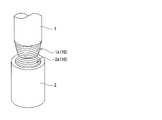
- FIG. 1 is a diagram showing an oil country tubular good and an oil country tubular good threaded joint;
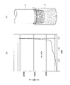
- FIG. It is a diagram (a) of a tightening chart in an actual well and a diagram (b) showing the initial set position at that time.
- It is a diagram (a) of a tightening chart in a conventional laboratory test and a diagram (b) showing an initial set position at that time.
- weight tongue test shows the installation example of the weight in a new laboratory test (weight tongue test).
- FIG. 2(a) is an example of a torque turn chart generated in an actual well.
- the conditions in Fig. 2(a) are a torque-turn chart (tightening chart) when a tightening test was performed using a 40-foot ( ⁇ 12m) actual length pin, simulating an actual well. .
- the initial set position is set so that, as shown in FIG. This is a starting example.
- a 9-5/8"53.5#Q125 JFELION TM screw was adopted as the pin. From the viewpoint of simulating an actual well, the pin was a little over 40 feet long (Range-3 length pin) was used.
- FIG. 2(a) is a chart when the pin is tightened with vertical tongs while being suspended by a crane that suspends the entire length of the pin from above the rig.
- This FIG. 2(a) can be regarded as a situation that often occurs in an actual well.
- This torque turn chart is interpreted in two phases.
- Phase 1 is the region of tightening untightening when the threads of the box and pin are not completely engaged.
- Phase 2 is defined as a region where the screws are meshed with each other and steady torque begins to rise and the torque increases in response to tightening.
- Fig. 2(a) What should be noted in Fig. 2(a) is that before the point where the torque continuously increases (in Fig. 2(a), the region where the number of revolutions is 6.3 rpm or less: phase 1), the torque does not stand up in principle. It should not be. However, in fact, in fact, in phase 1, the spike-like torque tends to rise irregularly and frequently. This suggests that in the Phase 1 region, the pin screw contacts the box screw irregularly and locally while rotating. This is the situation that occurs in tightening in actual wells. In phase 1, it means that destruction and peeling of the solid lubricating coating cannot be avoided to some extent depending on the design and optimization of the solid lubricating coating. What I would like to emphasize here is that the state in FIG. 2(a) is not the worst state intentionally created, but is a normal torque-turn chart of a sample with a solid lubricating coating.
- FIG. 3(a) is a torque-turn chart when using the same solid lubricating coating as in FIG. 2 and tightening with vertical power tongs.
- a pin having the same outer diameter, thickness, and thread type as those in FIG. 2 is used, but a short pin having a length of about 1 m is used as the pin. In this case, the short pin's own weight of 100 kg is applied to the box screw.
- FIG. 3(a) is a tightening chart (torque turn chart) when tightening is started from a state in which the screws are sufficiently meshed. That is, as shown in FIG.
- FIG. 3(b) it is a tightening chart (torque turn chart) when the exposed pin thread is about 1 to 3 threads at the start of initial tightening.
- the conditions of FIG. 3(a) are often used in conventional laboratory tests, and are examples of manual tightening until the screws are engaged.
- the load is small (no influence of large load), and there is no whirling of the screw in the initial stage (no influence of unbalanced load).
- FIG. 3(a) the unit of the horizontal axis is different from that in FIG. 2(a).
- the spike-like torque seen in FIG. 2(a) is not seen.
- the initial position for tightening with power tongs is often the position where the screws are hand-tightened until they mesh. For this reason, there is no behavior in phase 1 until the screws are meshed.
- the solid lubricating film that should occur before the screw is engaged is not destroyed (under conditions without phase 1), that is, only in the area of phase 2 after engagement. This is a test that evaluates only tightening and untightening.
- FIG. 4 shows FIGS. 2(a) and 3(a) in a state that facilitates comparison.
- 4A is an example of FIG. 2
- FIG. 4B is an example of FIG.
- the ideal solid lubricating coating should be such that the solid lubricating coating is not destroyed in the region (x) in FIG. 4(a). , to minimize concerns about breakage and delamination. Alternatively, some spikes may stand. This is a situation where the solid lubricating coating is damaged.
- the secondary product derived from the solid lubricating film where the film is broken or peeled off does not clog the screw gap during tightening and loosening, but on the contrary, adheres well to the screw and assists lubrication. preferably.
- the large-diameter oil country tubular goods screw generally has a higher tightening torque value and more play between the box screw and the pin screw. For this reason, it is inevitable that the solid lubricating coating will be destroyed and peeled off to some extent before the screws are fully meshed. Also, at the beginning of the test, at the stage of setting the pin screw to the box screw, the heavy weight of the pin makes it difficult to handle. For this reason, the pin screw is accidentally brought into contact with the box screw with a certain frequency, which also destroys and peels off the solid lubricating coating.
- a new laboratory test was devised in view of the actual tightening and loosening conditions of a well, and the evaluation by the new laboratory test was also referred to.
- an appropriate method for simulating tightening and loosening in an actual well is a method for simulating the tightening behavior that occurs when tightening oil country tubular goods screws in an actual well. This is used to identify the upper and lower limits of the parameters of this disclosure and to establish preferred ranges. It is necessary to evaluate the lubrication of oil well pipe screws by assuming what happens in an actual well. For that purpose, there is no choice but to evaluate by simulating what can happen in an actual well, or to evaluate using an actual long pin.
- the process of tightening and unfastening an oil country tubular good screw can be divided into two stages. Insert the pin screw into the box screw and turn it as it is, or turn it by hand until the screw bites to some extent to avoid cross threading.
- the pin when viewed from a distance, the pin is upright when tightening and untightening is performed. . This is called unbalanced load.
- the solid lubricating coating in areas where the threads do not mesh, the solid lubricating coating is easily damaged and partially peeled off. For this reason, the solid lubricating coating itself is designed with a solid lubricant, a binder resin, and other regulations so that the flakes do not clog the screw gaps or seize.
- a suitable range is defined for each component as described above. Furthermore, the film evaluation was completed by evaluating and judging lubrication in accordance with situations that can occur in an actual well, taking into account backlash (play) and conditions for applying a large load.
- This embodiment relates to a coating structure formed on a fastening surface of an oil country tubular goods screw actually used for oil/gas, and a threaded joint having the coating structure as a lubricating coating.
- This embodiment is characterized by a lubricating coating provided with a solid lubricating coating formed on the fastening surface of a threaded joint, and the thread structure itself of the threaded joint is not particularly limited.
- a known or novel thread structure may be adopted for the thread structure of the threaded joint.
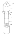
- An oil country tubular good is composed of a box 2 such as a coupling and a pin 1, for example, as shown in FIG.
- an oil well pipe threaded joint consists of a box 2 such as a coupling having a female thread 2a and a pin 1 having a male thread 1a.
- a lubricating coating comprising a solid lubricating coating is formed on the contact surface (fastening surface 10) of the threaded portion of at least one of the box 2 and the pin 1.
- box screws female thread side
- pin screws male thread side
- T&C Thread side
- the agent for forming the solid lubricating coating in this embodiment will be described below.
- the drug of this embodiment is composed of one or more solid lubricants dispersed in a binder resin as a matrix component.
- the main component of the solid lubricant is melamine cyanurate, and the average particle size of the melamine cyanurate is 0.1 ⁇ m or more and 10.0 ⁇ m or less.
- the main component of the solid lubricant is melamine cyanurate, which means that 80% by weight or more, preferably 90% by weight or more of the total weight of the solid lubricant is melamine cyanurate.
- Binder resins include alkyd resins and nitrocellulose.
- the alkyd resin and nitrocellulose comprise at least 85% by weight of the total binder resin component weight.
- the weight of nitrocellulose is preferably 0.5 to 3 times the weight of the alkyd resin.
- the solvent contained in the drug consists of one or more materials selected from mineral spirits, aromatics, alcohols, ester solvents, and ketone solvents.
- Aromatics are, for example, mineral spirits or toluene, xylene, naphtha, benzene and the like.
- Alcohols are, for example, ethanol, propanol, isopropanol, butanol and the like.
- ester-based solvents include butyl acetate, methyl acetate, and isobutyl acetate.
- Ketone solvents include, for example, methyl ethyl ketone, methyl isobutyl ketone, cyclohexanone, and acetone.
- the weight of the solvent is, for example, 20% or more and 80% or less of the total weight of the total weight of the solid lubricant and the total weight of the binder resin.
- the alkyd resin has an oil length of, for example, 10-60.
- the drug may contain a plasticizer.
- the plasticizer is, for example, one or more materials selected from dibutyl phthalate (DBP), dimethyl phthalate (DMP), and diethyl phthalate (DEP). When the plasticizer is contained, it is contained, for example, in an amount of 10 parts by weight or more and 20 parts by weight or less per 100 parts by weight of nitrocellulose.
- a lubricating coating comprising a solid lubricating coating is formed on the fastening surface of the threaded portion of at least one of the box and the pin.
- the solid lubricating coating is composed of a solid lubricant dispersed in a binder resin as a matrix component.
- the main component of the solid lubricant is melamine cyanurate, and the average particle size of the melamine cyanurate is 0.1 ⁇ m or more and 10.0 ⁇ m or less.
- Binder resins include alkyd resins and nitrocellulose. The alkyd resin and nitrocellulose comprise at least 85% by weight of the total binder resin component weight.
- the total weight of the solid lubricant is 10 parts by weight or more and 100 parts by weight or less per 100 parts by weight of the total weight of the binder resin, and the thickness of the solid lubricating coating is 10 ⁇ m or more and 150 ⁇ m or less.
- the lubricating coating may have an underlying layer 10B between the fastening surface and the solid lubricating coating (FIG. 7(b)).
- the underlying layer 10B is made of, for example, a Mn phosphate chemical conversion treatment film, a zinc phosphate chemical conversion treatment film, or an electroplated film containing one or more metals selected from Cu, Sn, and Zn.
- the solid lubricating coating has, for example, a pencil hardness of 2B or more.
- a lubricating coating comprising the solid lubricating coating is formed on the fastening surface of the threaded portion of at least one of the box and the pin.
- a lubricating coating comprising the solid lubricating coating is formed on the fastening surface of the threaded portion of one of the box and the pin.
- a second solid lubricating coating softer than the solid lubricating coating is formed on the fastening surface of the threaded portion of the other part of the box and the pin.
- the second solid lubricating coating is composed of, for example, a second binder resin as a matrix component and a second solid lubricant dispersed therein.
- the second binder resin contains a fluorine-based organic compound as a main component.
- the second solid lubricant component is composed of one or more compounds using a material selected from the group X fatty acids below and a material selected from the group Y metal elements below.
- Group X stearic acid, isostearic acid, behenic acid, lauric acid, 12-hydroxystearic acid
- Group Y Li, Na, Mg, Al, Ca, Zn, Ba
- the fluorine solvent of group Z accounts for 90% or more of the weight of the solvent component.
- ⁇ Z group HFC, HFE, HFO
- the second solid lubricating coating preferably has a pencil hardness of 3B or less.
- the inventor simply selected MCA as a solid lubricant, selected a binder resin composed of nitrocellulose and an alkyd resin as a binder resin, and tried to make a solid lubricating coating using these as main components.
- MCA solid lubricant
- a binder resin composed of nitrocellulose and an alkyd resin as a binder resin
- the solid lubricating coating has improved seizure resistance and can withstand use in actual wells, its chemical agent, oil country tubular goods threaded joints, and metal materials.
- the present invention has been completed by discovering a suitable range of each drug that covers the range expanded to . Furthermore, it demonstrates in detail.
- the solid lubricating coating of this embodiment is formed by dispersing a solid lubricant mainly composed of MCA (melamine cyanurate) in a binder resin composed of an alkyd resin and nitrocellulose.
- MCA melamine cyanurate
- the reason why MCA was selected as the main component of the solid lubricant is as follows. In other words, it is excellent as a lubricant capable of obtaining high lubrication, and can maintain high lubrication even when there is some seizure and localized high temperature. During tightening and loosening, the pin screw and the box screw may rub against each other and generate frictional heat, but this is to maintain sufficient lubrication.
- the reason for choosing a binder resin made of alkyd resin and nitrocellulose is as follows.
- the selection of alkyd resin and nitrocellulose is a horizontal development of technology from so-called lacquer paint. Lacquer paints are characterized by being able to cure at normal temperature and pressure without heat treatment if an alkyd resin with an appropriate oil length is selected. For this reason, it is possible to easily form a film, and it is also possible to apply multiple layers. Furthermore, the lacquer coating can be mixed with the above-mentioned MCA without any particular problem.
- the binder resin is preferably used to obtain a film as hard as possible. Desirably, it has a pencil hardness of about HB to 2H. In addition, the binder resin needs to overcome its brittleness so as not to cause peeling such that most of it is taken away (uprooted peeling), rather than peeling off little by little.
- the film thickness of the solid lubricating coating should be at least 10 ⁇ m. If the film thickness is 10 ⁇ m or more, it is possible to maintain lubricating properties and corrosion resistance. It is difficult to generalize the upper limit of the film thickness because the gap between the box screw and the pin screw differs depending on the type and design of the oil country tubular goods screw. In this embodiment, for example, the upper limit is set to 150 ⁇ m. Since many oil country tubular goods screws are designed with a gap of 100 to 200 ⁇ m between screw ridges as a target, 150 ⁇ m is defined as the upper limit. More preferably, the film thickness is 10 to 50 ⁇ m.
- the gaps between peaks and valleys of male and female threads may be 100 to 200 ⁇ m as described above.
- the clearance between the stabbing flanks of the male-to-female threads and the clearance between the load flanks also change when tightening and loosening.
- the film thickness should be as small as possible, and the preferred range is 10 ⁇ m to 50 ⁇ m.
- these film thicknesses mean the film thickness in the As-formed state before the first tightening.
- the binder resin is scraped off to some extent, and the film thickness applied at room temperature is actually crushed and becomes a thin film, so it is assumed in the actual well. Even if the thickness is greater than or equal to the gap, the problem of seizing does not occur because of this.
- ⁇ About solid lubricants> Contains one or more solid lubricants.
- the solid lubricant contains melamine cyanurate (MCA) in an amount of 80% by weight or more. Melamine cyanurate has an average particle size of 0.1 to 10.0 ⁇ m.
- MCA melamine cyanurate
- a solid lubricant containing MCA as a main component is dispersed in the binder resin.
- the components of the present disclosure are that MCA accounts for 80% of the total weight of the solid lubricant as a denominator, and that the average particle size of MCA is 0.1 ⁇ m or more and 10.0 ⁇ m or less.
- the average particle size of MCA is a parameter that means the particle size at an integrated value of 50% in the particle size distribution determined by a laser diffraction/scattering method or the like.
- the average particle size of MCA is preferably 2 ⁇ m or less.
- coarse MCA of about 10 to 20 ⁇ m may very rarely be included.
- the reason for defining a more suitable range is to eliminate the concern that seizure may occur due to the inclusion of coarse MCA.
- the fact that MCA is 80% by weight or more of the solid lubricant means that MCA accounts for the majority of solid lubricants.
- the total weight of the solid lubricant is used as a parameter, even if it contains less than 20% of other solid lubricants, it is defined in the sense that there is no adverse effect on the design based on MCA. .
- the range in which MCA can be mainly handled is set to 80% or more.
- Other solid lubricants that can be assumed to be mixed at a maximum of less than 20% include, for example, BN with the same white tone, PTFE with excellent lubricity, and the like.
- Other solid lubricants include graphite, graphite fluoride, MoS 2 , WS 2 , mica, talc, and the like.
- an oil-based substance may be mixed as a kind of solid lubricant.
- carna wax perfluoropolyether
- CTFE oil low polymer of chlorotrifluoroethylene
- the lubrication of the MCA can be maintained or improved by incorporating an oil-based material.
- the binder resin component includes an alkyd resin and nitrocellulose, the combination comprising at least 85% by weight of the total binder resin component weight.
- the proportion of nitrocellulose is 0.5 to 3 times the weight of the alkyd resin.
- the alkyd resin has an oil length of 10-60.
- a plasticizer for example, one type or two or more types of phthalates may be mixed.
- the phthalate ester is preferably contained in an amount of 10 parts by weight or more and 20 parts by weight or less when the weight of the nitrocellulose is 100 parts by weight. Examples of phthalate ester candidates include dibutyl phthalate (DBP), dimethyl phthalate (DMP), and diethyl phthalate (DEP).
- nitrocellulose lacquer was used as a component of the binder resin.
- Nitrocellulose lacquers are compatible nitrocellulose and alkyd resins dissolved in fast-drying solvents. When it is applied, the solvent evaporates on the applied surface and a hard film is obtained. Although the nitrocellulose lacquer film is hard, it is also brittle, so it must be given some degree of flexibility.
- the film quality is improved by adding alkyd resin. In this case, the alkyd resin is 0.5 to 3 times the weight of the nitrocellulose component. If it is less than 0.5 times, brittle characteristics are conspicuous.
- the alkyd resin preferably has an oil length of 10 or more and less than 60. If it is less than 10, heat treatment is required to form a film. If it exceeds 60, the viscosity is too high, and lumps may occur during brushing or spraying, and uniform application may not be possible. Moreover, a large oil length is not good because it directly leads to a decrease in the strength of the alkyd resin. Also, as mentioned above, nitrocellulose is hard but accompanied by brittleness. For this reason, an alkyd resin is mixed to form a resin film.
- plasticizers are preferably contained in an amount of 10 parts by weight or more and 20 parts by weight or less when the weight of the nitrocellulose is 100 parts by weight. Even with this level of content, surface cracks can be minimized.
- nitrocellulose has a property of being weak against ultraviolet rays. Therefore, it is preferable that the surface coated with the solid lubricating coating is not exposed to direct sunlight. Therefore, it is preferable to form a solid lubricating coating on the box thread side.
- a protector attached When applying the solid lubricating coating of this embodiment to the pin thread side, it is recommended to use it with a protector attached.
- a trace amount of oxybenzone-based ultraviolet-absorbing agent of 5 parts by weight or less per 100 parts by weight of nitrocellulose.
- it may contain additives for adjusting the drying property and liquid viscosity of the entire drug and adjusting the hardness when it becomes a solid lubricating coating, and a solvent that does not remain in the solid lubricating coating after drying.
- a drug contains a solvent.
- the solvent is, for example, one or more of mineral spirits or alcohols such as toluene, xylene, naphtha, benzene, ethanol, propanol, isopropanol and butanol.
- the quick drying of the applied drug is intended. Therefore, it is preferable to dissolve the coating components (nitrocellulose, alkyd resin, MCA, etc.) in a highly volatile organic solvent.
- the term "quick-drying property" as used herein refers to the ability of the film to harden after about 5 minutes of natural standing. Depending on the situation, an air blow or the like may be used in combination during film formation.
- the weight of the solvent should be 20% or more and 80% or less of the total weight of the total weight of the binder resin mainly composed of nitrocellulose and alkyd resin and the total weight of the solid lubricant mainly composed of MCA. is preferred. If it exceeds 80%, the chemical solution itself becomes thin and difficult to apply, and the drying time is too long. For this reason, it is difficult to use. On the other hand, if it is less than 20%, the viscosity of the liquid becomes too high, making uniform application difficult.
- the total weight of the binder resin is 100 parts by weight
- the total weight of the solid lubricant should be 10 parts by weight or more and 100 parts by weight or less.
- the total weight of the binder resin which is mainly composed of nitrocellulose and alkyd resin
- the solid lubricating coating preferably has a pencil hardness of 2B or more. Assuming the lubrication behavior that the solid lubricating film receives in an actual well, the solid lubricating film tends to be easily damaged during the behavior until the screws are engaged, that is, when the OCTG screws are tightened with backlash. It is in. However, hardening the film quality minimizes the damage. Specifically, the solid lubricating coating is made to be hardened to 2B or more so as not to be scraped off. In this embodiment, the solid lubricating coating is a hard film. This keeps the film lubricated as a non-brittle film quality so as not to uproot it during tightening.
- nitrocellulose and alkyd resin as main components and adjust the hardness of the binder resin so that the hardness of the binder resin is 2B or more to form a hard film.
- This hardness adjustment can be achieved by the ratio of nitrocellulose to alkyd resin, particle size and concentration of MCA, as described above.
- the pencil hardness evaluation shall be measured by the method specified in JIS K 5600-5-4 (1999).
- the JIS standard clearly states that this standard is a translation of the "ISO/DIS 15184, Paints and varnishes - Determination of film hardness by pencil test” standard.
- the pencil hardness test method itself was evaluated based on the JIS standards.
- the reason why the film hardness was evaluated in terms of pencil hardness is that the pencil hardness test method is a “scratch” evaluation with a pencil, which resembles the peeling behavior of the solid lubricating film on the male and female threads of oil country tubular goods. It is also because of the film hardness evaluation method caused by "scratching".
- the film hardness measurement method, Rockwell, Vickers, Shore, and Knoop caused by indentation which may be used in coating films, etc., has a thin coating film and is affected by the substrate, so pencil hardness is used in this disclosure. .
- the solid lubricating coating 10A may be formed directly on the base steel material (fastening surface) (see FIG. 7(a)). Alternatively, as shown in FIG. 7B, the solid lubricating coating may be formed after forming the base layer 10B.
- the adhesion of the solid lubricating coating can be enhanced by having such a base layer.
- the underlying layer 10B include a Mn phosphate chemical conversion treatment film, a zinc phosphate chemical conversion treatment film, and an electroplating film containing at least one of Cu, Sn, and Zn.
- the above solid lubricating coating may be formed on both the pin thread and the box thread of the oil country tubular good, or may be formed on only one of them.
- the fastening surface of the screw on the other side may be cut or shot-blasted.
- a soft second solid lubricating coating may be formed on the fastening surface of the other screw.
- the second solid lubricating coating is composed of, for example, a second binder resin as a matrix component and a second solid lubricant dispersed therein.
- the second binder resin contains a fluorine-based organic compound as a main component.
- the second solid lubricant component is composed of one or more compounds using a material selected from the group X fatty acids below and a material selected from the group Y metal elements below.
- Group X stearic acid, isostearic acid, behenic acid, lauric acid, 12-hydroxystearic acid
- Group Y Li, Na, Mg, Al, Ca, Zn, Ba
- the following Z group fluorine solvent accounts for 90% or more of the weight of the solvent component.
- ⁇ Z group HFC, HFE, HFO
- the second solid lubricating coating is preferably soft with a hardness of 3B or less. While the aforementioned solid lubricating coating is hard with a pencil hardness of 2B or more, the second solid lubricating coating is preferably softer than that for the following reasons. That is, contact with a hard/soft film can achieve more favorable friction than contact between hard objects. Specifically, it can be expected that the solid lubricant will always be gradually exposed and supplied while the soft film is scraped off, so that low friction is likely to be achieved.
- This embodiment defines each material from the viewpoint of achieving lubricating properties that can withstand the environment that may occur in an actual well. Moreover, when specifying the upper and lower limits, confirmation (testing) was carried out under conditions that conformed to the tightening and loosening conditions in actual wells. In the method using horizontal and vertical power tongs using short pins, as in normal laboratory tests, the tightening and unfastening conditions do not conform to the actual conditions, and in the case of a solid lubricating film, the conditions are loose. end up For this reason, it is meaningless to explain the upper and lower limits of each material by evaluating them in a normal laboratory test.
- the solid lubricating coating may be damaged, peeled off, or in severe cases, completely peeled off. Based on this, the upper and lower limits of the preferred range were selected for the parameters of this embodiment.
- a test was conducted with the apparatus configuration shown in FIG. 5 based on the above new laboratory test conditions.
- we will basically evaluate under conditions that can be realized, such as a large load during tightening and an unbalanced load during tightening and untightening. For example, in the case of a process in which a large load equivalent to an actual size pin is applied to the joint portion and the screws are tightened, rattling until the screws are engaged is taken into consideration. In addition, in the case of the process of loosening the screws, the fact that the screws are disengaged from each other and rattling occurs is reflected.
- the new lab test uses the vertical power tongs 4.
- a short pin 1 is employed as a test pin. However, a load can be applied to the upper portion of the pin 1 by the weight 3 and the load can be removed. The short screw 1 and the box screw 2 are tightened by the pin screw portion 1a and the box screw portion 2a.
- the initial temporary tightening position is set so that the pin thread 1a is exposed from the box screw 2 by half of the total number of threads. (See FIG. 2(b)). This is one of the causes of rattling.
- a weight 3 is attached to the upper end of the pin 1, which is the end of the box screw 2 opposite to the tightening screw.
- the weight of the weight 3 is a load corresponding to one to three actual size pins, which is calculated based on the pin's outer diameter and wall thickness.
- 9-5/8"53.5# is about 1t load (2,200Lb) per one, and about 3 tons (6,600Lb) if three are connected.
- the weight 3 illustrated in FIG. 5 consists of a weight main body 3A and an insertion rod 13 as shown in FIG.
- the insertion rod 13 is welded to the lower surface of the weight body 3A and arranged at an axially symmetrical position with respect to the weight 3.
- the weight is attached to the pin by loosely inserting the insertion rod 13 into the pin 1.
- ⁇ Reference numeral 1c denotes an inner diameter surface of the pin 1.
- the insertion rod 13 and the pin 1 are previously provided with holes 1d and 13a through which the pin 1 and the insertion rod 13 are inserted when the weight 3 is attached as described above.
- the weight 3 and the pin 1 are integrated by inserting the through rod 12 into the holes 1d and 13a.
- a swivel-type hook 11 is welded to the axial center position of the upper part of the weight 3, and the weight 3 is hung from a hanging device 20 on the ceiling via a hanging chain 21.
- - ⁇ As a result by adjusting how the weight is lifted by the suspension device 20, the magnitude of the load of the weight on the pin can be adjusted.
- the secondary product from the component derived from the solid lubricating film which is released into the screw gap due to unavoidable peeling, does not move following tightening and loosening, It is possible to simulate a clogging situation that causes burn-in. Alternatively, other situations can be simulated in which the coating itself is uprooted. As a result, the upper and lower limits of the parameters relating to the solid lubricating coating can be defined in accordance with the actual well conditions. After tightening was completed, the pin screw and the box screw were separated, the debris from the solid lubricating film on the surface was blown off with an air blow, the surface was checked, and the evaluation was performed by continuing tightening again. .
- the components and others are specified in order to realize lubricating properties that can withstand the environment that may occur in an actual well. Moreover, when specifying the upper and lower limits, they were determined by confirming conditions that conformed to the tightening and loosening conditions in actual wells.
- an oil country tubular goods threaded joint having lubrication performance during tightening that takes into consideration actual well-equivalent conditions that may occur in an actual well environment is obtained.
- the actual well-equivalent condition is that the weight of the pin is applied to the box from above (large load), and the load is applied obliquely (unbalanced load) due to the deviation of the axis.
- the application may be expanded to include not only the lubrication of oil country tubular good threads, but also other metal materials.
- membranes, but also drugs for making membranes are targeted.
- the present disclosure can also take the following configuration.
- An agent for forming a solid lubricating coating on the threaded portion of an oil country tubular good wherein a solid lubricant is dispersed in a binder resin, the main component of the solid lubricant is melamine cyanurate, and the melamine cyanide
- the nurate has an average particle size of 0.1 ⁇ m or more and 10.0 ⁇ m or less, contains an alkyd resin and nitrocellulose as the binder resin, and contains 85% by weight or more of the total binder resin component weight of the alkyd resin and nitrocellulose.
- the total weight of the solid lubricant is 10 parts by weight or more and 100 parts by weight or less with respect to 100 parts by weight of the total weight of the binder resin.
- the weight of the nitrocellulose is 0.5 to 3 times the weight of the alkyd resin.
- a solvent is included, and the solvent is made of one or more materials selected from mineral spirits, aromatics, alcohols, ester solvents, and ketone solvents, and the weight of the solvent is It is 20% or more and 80% or less of the total weight of the total weight of the solid lubricant and the total weight of the binder resin.
- the alkyd resin has an oil length of 10-60.
- (5) Contains one or more materials selected from dibutyl phthalate (DBP), dimethyl phthalate (DMP), and diethyl phthalate (DEP) as a plasticizer, and the plasticizer reduces the weight of the nitrocellulose.
- the content is 10 parts by weight or more and 20 parts by weight or less per 100 parts by weight.
- the solid lubricating coating is composed of a solid lubricant dispersed in a binder resin, the main component of the solid lubricant is melamine cyanurate, and the average particle size of the melamine cyanurate is 0.1 ⁇ m
- the total weight of the solid lubricant is 10.0 ⁇ m or more, contains an alkyd resin and nitrocellulose as the binder resin, and contains the alkyd resin and nitrocellulose in an amount of 85% by weight or more of the total weight of the binder resin component.
- the total weight of the binder resin is 10 parts by weight or more and 100 parts by weight or less, and the thickness of the solid lubricating coating (consisting of the binder resin, the solid lubricant, and other additives) is 10 ⁇ m It is more than 150 micrometers or less.
- the lubricating coating has an underlying layer between the fastening surface of the threaded portion and the solid lubricating coating, and the underlying layer is a Mn phosphate chemical conversion treatment film, a zinc phosphate chemical conversion treatment film, or Cu, An electroplated film containing one or more metals selected from Sn and Zn.
- the solid lubricating coating has a pencil hardness of 2B or more.
- An oil well pipe threaded joint made of pipes.
- a lubricating coating comprising the solid lubricating coating is formed on the fastening surface of the threaded portion of one of the box and the pin, and the threaded portion of the other of the box and the pin is fastened.
- a second solid lubricating coating softer than the solid lubricating coating is formed on the surface.
- the second solid lubricating coating is configured by dispersing the second solid lubricant in the second binder resin, and the second binder resin is mainly composed of a fluorine-based organic compound, and the above
- the second solid lubricant is composed of one or more compounds using a material selected from the group X fatty acids below and a material selected from the group Y metal elements below.
- the second solid lubricating coating has a pencil hardness of 3B or less.
- Judgment criteria are as follows.
- the casing size was judged to be acceptable when tightening and unfastening 3 times or more, and as excellent when 5 times.
- a tubing size of 5 times or more was judged as acceptable, and a tubing size of 10 times or more was evaluated as excellent.
- the regulation of the casing size is in line with the regulation of ISO13679. Tubing, on the other hand, was considered acceptable from 5 times or more, which is lower than the ISO 13679 specification.
- the load applied by the weight tongs was a 1 ton load for one 9-5/8′′ actual size, and a weight of 1 ton load was used. Then, the weight was attached to the top of the pin screw. The initial tightening position was tightened only to a position where half of the total number of pin threads were exposed from the box screw, that is, tightening was performed from a state in which the threads did not mesh with each other. That is, this example was carried out using the apparatus shown in FIGS.
- Example 1 describes lubrication property evaluation using weight tongs. Tables 1 to 4 describe the conditions and evaluation results of each example.
- a solid lubricating film is also called a coating film.
- the second solid lubricating coating is also called a soft coating.
- No. 1 to No. 4 is a comparative evaluation result regarding the difference in power tongs to be evaluated.
- No. 1 to No. All three cases have the same conditions, with material parameters in the preferred range. However, only the conditions for tightening and unfastening with tongs are different.
- No. 1 is horizontal tongs
- No. 2 is a simple vertical tong
- 3 uses vertical tongs, but adopts a test based on a new laboratory test with a weight attached (hereinafter also referred to as a weight tong test).
- No. 4 corresponds to the results of a tightening tightening test using a Range-3 pipe (12 m or more, about 40 ft or more) in a simulated well.
- No. 1 is a case in which tightening and unfastening were completed 10 times or more (stopped at 10 times).
- No. In 2 tightening and unfastening were performed up to 7 times.
- No. 3 shows that the number of times of tightening and unfastening was 3 times and 4 times after 2 times.
- No. 4 shows that the number of times of tightening was 3 times, 3 times, and 4 times after 3 times.
- No. In 1 the self weight of the short pin screw is not applied to the coupling screw.
- No. In 1 since the shaft is also adjusted, no biased load is applied due to looseness of the screw.
- No. 2 the test was conducted in a state where the weight of one short pin was applied to the coupling thread. In addition, if it is the size of this case, it is a short pin of 1m, and self-weight is about 100kg.
- No. 3 is a simulation of a state in which 1 ton corresponding to one actual size pin is applied. And No. In 3, as described above, tightening starts from a half-tightened state where the set position of the pin is intentionally set so that about half of the pin thread is exposed to the coupling screw. As a result, the screws do not mesh with each other and there is backlash, as occurs in an actual well. In other words, the tightening and untightening conditions simulate a state in which the solid lubricating coating is damaged.
- No. 4 corresponds to tightening and undoing conditions under conditions closely resembling tightening conditions in an actual well.
- No. 3, No. 4 corresponds to the example of the present invention.
- No. 1 and 2 are comparative reference examples, although the number of times of tightening and unfastening exceeds the acceptance line.
- No. 3 and 4 correspond to examples that can be said to be examples of the present invention.
- No. 1 or No. The meaning of 2 is that evaluation is performed with weight tongs, which are close to actual wells, and unless the upper and lower limits of the parameters defined in the present disclosure are explained, the evaluation will be lenient. In other words, these methods, which have been used in numerous patent documents so far, result in lenient evaluations of solid lubricating coatings. This suggests that conventional laboratory testing is not suitable as an evaluation method. It also means that the weight tongs test method can simulate real well conditions.
- No. 5 to No. 8 is an example compared under substantially the same conditions. This example is mainly for the study of changing the film thickness of the solid lubricating film, the presence or absence of shot blasting, the presence or absence of a plasticizer, and the presence or absence of a different type of solid lubrication film on the pin screw side.
- No. 5 is a case in which the film thickness exceeds the upper limit of the present disclosure, and the other parameters are in a suitable range.
- No. Case 5 is a case in which the solid lubricating film, which was damaged during tightening and undoing, clogged the screw gap and seized early because the film was thick. No.
- No. 7 is No. It is an example of the present invention having a solid lubricating coating on the coupling screw under the same conditions as in No. 6 and forming a soft film on the pin screw side.
- a solid lubricant mainly composed of MCA is used, and a screw having a film formed by mixing nitrocellulose and alkyd resin within the scope of the present disclosure is formed.
- the film thickness of the solid lubricating coating is set to the upper limit of 150 ⁇ m, which is an example of the present invention.
- No. 9, 10 No. Case No. 9 is a case of a solid lubricant consisting of 80 wt% MCA and 20 wt% BN for solid lubrication. No. All the 9 cases are within the preferred range of parameters and correspond to the examples of the present invention.
- No. Case 10 is a case in which the ratio of MCA in the solid lubricant is less than the specified range of disclosure and the average particle size of MCA is larger than the specified range of disclosure.
- No. The 10 cases are cases in which the seizure occurred early in the tightening untightening test, although the other specifications were within the appropriate range, and corresponded to the comparative examples.
- No. 12 and No. No. 14 has components adjusted within a suitable range and corresponds to an invention example.
- No. 11, 13 and 15 correspond to comparative examples.
- No. No. 11 is a case in which 20% melamine resin is added in addition to the components of nitrocellulose and alkyd binder resin, and nitrocellulose is blended in a larger amount than specified. This condition is also one of the causes.
- No. 11 is a case in which the film quality has become brittle. No. In No. 11, there was only one case in which the number of times of tightening and unfastening exceeded 5 times, but the remaining 2 cases were comparative examples with less than 3 times. No. No. No.
- No. 13 is a case where the solid lubricant is too small with respect to the binder resin, so lubrication cannot be maintained and seizure occurs.
- No. 15 is a case where the solid lubricant is blended beyond the specified range of disclosure, the blending ratio of nitrocellulose is lower than specified, and the oil length of alkyd resin is larger than specified. be. And no. No. 15 is a case where the number of times of tightening and unfastening could not reach the regulation.
- Example 2 Among the examples of Example 1, several examples were selected and subjected to a salt spray test to confirm their corrosion resistance. Of the cases shown in Example 1, No. 3, 6, 14 carbon steel-based OCTG thread conditions were picked up and salt sprayed. The material was newly filmed into coupling samples for this salt spray test. Moreover, as a comparative example, SPCC (ordinary general mild steel thin steel plate/cold-rolled annealed plate) with a thickness of 0.8 mm was also used (condition A).
- SPCC ordinary general mild steel thin steel plate/cold-rolled annealed plate
- the oil country tubular good thread material was tightened and tightened once with a protector on both ends of the coupling screw, and then left as it was (No. 3-2, 6-2, 14-2), and again with the protector. Attached (corresponding to the second tightening: No. 3-3, 6-3, 14-3) was adopted. Then place each sample side by side. That is, the corrosion test was performed by lining up the samples without standing them up and performing the salt spray test. At this time, the pin screw was used as a sample with only a screw thread, and the side with the screw was tightened and loosened once with a protector. An imide tape was pasted on the outside of the pipe where the protector was not attached again to protect the inside of the pipe from water entry.
Landscapes
- Chemical & Material Sciences (AREA)
- Chemical Kinetics & Catalysis (AREA)
- General Chemical & Material Sciences (AREA)
- Oil, Petroleum & Natural Gas (AREA)
- Organic Chemistry (AREA)
- Non-Disconnectible Joints And Screw-Threaded Joints (AREA)
- Lubricants (AREA)
Abstract
Priority Applications (4)
| Application Number | Priority Date | Filing Date | Title |
|---|---|---|---|
| BR112023025070A BR112023025070A2 (pt) | 2021-05-31 | 2022-05-24 | Agente, produtos tubulares para campos petrolíferos e junta rosqueada para produtos tubulares para campos petrolíferos |
| CN202280038774.6A CN117441002A (zh) | 2021-05-31 | 2022-05-24 | 试剂、油井管和油井管螺纹接头 |
| JP2022550249A JP7193681B1 (ja) | 2021-05-31 | 2022-05-24 | 薬剤、油井管、及び油井管ねじ継手 |
| EP22815919.0A EP4332204A1 (fr) | 2021-05-31 | 2022-05-24 | Agent chimique, tuyau de puits de pétrole et joint à vis pour tuyau de puits de pétrole |
Applications Claiming Priority (2)
| Application Number | Priority Date | Filing Date | Title |
|---|---|---|---|
| JP2021-091464 | 2021-05-31 | ||
| JP2021091464 | 2021-05-31 |
Publications (1)
| Publication Number | Publication Date |
|---|---|
| WO2022255169A1 true WO2022255169A1 (fr) | 2022-12-08 |
Family
ID=84323164
Family Applications (1)
| Application Number | Title | Priority Date | Filing Date |
|---|---|---|---|
| PCT/JP2022/021281 WO2022255169A1 (fr) | 2021-05-31 | 2022-05-24 | Agent chimique, tuyau de puits de pétrole et joint à vis pour tuyau de puits de pétrole |
Country Status (6)
| Country | Link |
|---|---|
| EP (1) | EP4332204A1 (fr) |
| JP (1) | JP7193681B1 (fr) |
| CN (1) | CN117441002A (fr) |
| AR (1) | AR125984A1 (fr) |
| BR (1) | BR112023025070A2 (fr) |
| WO (1) | WO2022255169A1 (fr) |
Citations (5)
| Publication number | Priority date | Publication date | Assignee | Title |
|---|---|---|---|---|
| JP2004053013A (ja) * | 2002-05-31 | 2004-02-19 | Sumitomo Metal Ind Ltd | 鋼管用ねじ継手 |
| WO2014024755A1 (fr) * | 2012-08-06 | 2014-02-13 | 新日鐵住金株式会社 | Raccord fileté tubulaire et composition de formation de film lubrifiant utilisée pour celui-ci |
| WO2015016322A1 (fr) * | 2013-07-31 | 2015-02-05 | ミネベア株式会社 | Composition de résine thermodurcissable, élément coulissant et procédé de production dudit élément coulissant |
| WO2020149310A1 (fr) * | 2019-01-16 | 2020-07-23 | 日本製鉄株式会社 | Joint fileté pour tuyaux et procédé de production d'un joint fileté pour tuyaux |
| JP2021091464A (ja) | 2019-12-12 | 2021-06-17 | 信越ポリマー株式会社 | 巻回体用化粧箱 |
-
2022
- 2022-05-24 WO PCT/JP2022/021281 patent/WO2022255169A1/fr active Application Filing
- 2022-05-24 EP EP22815919.0A patent/EP4332204A1/fr active Pending
- 2022-05-24 JP JP2022550249A patent/JP7193681B1/ja active Active
- 2022-05-24 BR BR112023025070A patent/BR112023025070A2/pt unknown
- 2022-05-24 CN CN202280038774.6A patent/CN117441002A/zh active Pending
- 2022-05-27 AR ARP220101401A patent/AR125984A1/es unknown
Patent Citations (5)
| Publication number | Priority date | Publication date | Assignee | Title |
|---|---|---|---|---|
| JP2004053013A (ja) * | 2002-05-31 | 2004-02-19 | Sumitomo Metal Ind Ltd | 鋼管用ねじ継手 |
| WO2014024755A1 (fr) * | 2012-08-06 | 2014-02-13 | 新日鐵住金株式会社 | Raccord fileté tubulaire et composition de formation de film lubrifiant utilisée pour celui-ci |
| WO2015016322A1 (fr) * | 2013-07-31 | 2015-02-05 | ミネベア株式会社 | Composition de résine thermodurcissable, élément coulissant et procédé de production dudit élément coulissant |
| WO2020149310A1 (fr) * | 2019-01-16 | 2020-07-23 | 日本製鉄株式会社 | Joint fileté pour tuyaux et procédé de production d'un joint fileté pour tuyaux |
| JP2021091464A (ja) | 2019-12-12 | 2021-06-17 | 信越ポリマー株式会社 | 巻回体用化粧箱 |
Non-Patent Citations (1)
| Title |
|---|
| TSURU ET AL., JOURNAL OF JAPAN PETROLEUM INSTITUTE, vol. 61, no. 6, 1996, pages 527 - 536 |
Also Published As
| Publication number | Publication date |
|---|---|
| JP7193681B1 (ja) | 2022-12-20 |
| AR125984A1 (es) | 2023-08-30 |
| BR112023025070A2 (pt) | 2024-02-27 |
| EP4332204A1 (fr) | 2024-03-06 |
| JPWO2022255169A1 (fr) | 2022-12-08 |
| CN117441002A (zh) | 2024-01-23 |
Similar Documents
| Publication | Publication Date | Title |
|---|---|---|
| US6827996B2 (en) | Threaded joint for steel pipes and process for the surface treatment thereof | |
| RU2281429C2 (ru) | Резьбовое соединение для стальных труб | |
| JP5124887B2 (ja) | 管ねじ継手 | |
| JP5736516B2 (ja) | 管状ねじ継手とそれに使用する潤滑被膜形成用組成物 | |
| JP2003042353A (ja) | 耐焼付き性に優れた鋼管用ねじ継手 | |
| WO2014042144A1 (fr) | Composition utilisée pour fabriquer un film de revêtement solide, et raccord fileté tubulaire | |
| JP6025994B2 (ja) | 潤滑被膜形成用組成物及び鋼管用ねじ継手 | |
| JP5145684B2 (ja) | 鋼管用ねじ継手に適した潤滑被膜形成用組成物 | |
| WO2015141159A1 (fr) | Composition de revêtement lubrifiant solide, joint fileté pour tuyaux comprenant un revêtement lubrifiant solide formé à l'aide de ladite composition, et procédé de production dudit joint fileté pour tuyaux | |
| JP2004053013A (ja) | 鋼管用ねじ継手 | |
| EA023235B1 (ru) | Резьбовое соединение труб, имеющее улучшенные характеристики при высоком крутящем моменте | |
| US20080038083A1 (en) | Fasteners Coated with Boron Nitride and Means for Securing Fasteners | |
| US20150240119A1 (en) | Process for producing a dry polyamide-imide film with high galling resistance on a threaded tubular component from an aqueous dispersion which is free of carcinogenic substances | |
| JP7193681B1 (ja) | 薬剤、油井管、及び油井管ねじ継手 | |
| WO2024043133A1 (fr) | Tuyau de puits de pétrole, joint à vis de tuyau de puits de pétrole et matériau de revêtement | |
| JP7241249B1 (ja) | 固体潤滑被膜形成用の薬剤、油井管、油井管ねじ継手、及び油井管の製造方法 | |
| JP7474449B2 (ja) | 固体潤滑被膜形成用の薬剤、油井管、及び油井管ねじ継手 | |
| JP3767668B2 (ja) | 油井管用ねじ継手 | |
| WO2022255168A1 (fr) | Agent chimique pour formation de film lubrifiant solide, tuyau de puits de pétrole et joint fileté de tuyau de puits de pétrole | |
| WO2024043131A1 (fr) | Agent chimique pour formation de film lubrifiant solide, procédé de fabrication ainsi que procédé d'application de cet agent chimique, tuyau pour puits de pétrole, et joint fileté de tuyau pour puits de pétrole | |
| WO2023063384A1 (fr) | Tuyau métallique pour puits de pétrole |
Legal Events
| Date | Code | Title | Description |
|---|---|---|---|
| ENP | Entry into the national phase |
Ref document number: 2022550249 Country of ref document: JP Kind code of ref document: A |
|
| 121 | Ep: the epo has been informed by wipo that ep was designated in this application |
Ref document number: 22815919 Country of ref document: EP Kind code of ref document: A1 |
|
| WWE | Wipo information: entry into national phase |
Ref document number: 18564198 Country of ref document: US |
|
| WWE | Wipo information: entry into national phase |
Ref document number: P6003101/2023 Country of ref document: AE |
|
| WWE | Wipo information: entry into national phase |
Ref document number: 202280038774.6 Country of ref document: CN Ref document number: MX/A/2023/014267 Country of ref document: MX Ref document number: 2022815919 Country of ref document: EP |
|
| WWE | Wipo information: entry into national phase |
Ref document number: 2023131446 Country of ref document: RU |
|
| REG | Reference to national code |
Ref country code: BR Ref legal event code: B01A Ref document number: 112023025070 Country of ref document: BR |
|
| ENP | Entry into the national phase |
Ref document number: 2022815919 Country of ref document: EP Effective date: 20231129 |
|
| NENP | Non-entry into the national phase |
Ref country code: DE |
|
| WWE | Wipo information: entry into national phase |
Ref document number: 523451779 Country of ref document: SA |
|
| ENP | Entry into the national phase |
Ref document number: 112023025070 Country of ref document: BR Kind code of ref document: A2 Effective date: 20231129 |