WO2020149262A1 - 光コネクタおよび光接続構造 - Google Patents
光コネクタおよび光接続構造 Download PDFInfo
- Publication number
- WO2020149262A1 WO2020149262A1 PCT/JP2020/000878 JP2020000878W WO2020149262A1 WO 2020149262 A1 WO2020149262 A1 WO 2020149262A1 JP 2020000878 W JP2020000878 W JP 2020000878W WO 2020149262 A1 WO2020149262 A1 WO 2020149262A1
- Authority
- WO
- WIPO (PCT)
- Prior art keywords
- ferrule
- plug frame
- optical
- optical connector
- fiber
- Prior art date
- Legal status (The legal status is an assumption and is not a legal conclusion. Google has not performed a legal analysis and makes no representation as to the accuracy of the status listed.)
- Ceased
Links
Images


Classifications
-
- G—PHYSICS
- G02—OPTICS
- G02B—OPTICAL ELEMENTS, SYSTEMS OR APPARATUS
- G02B6/00—Light guides; Structural details of arrangements comprising light guides and other optical elements, e.g. couplings
- G02B6/24—Coupling light guides
- G02B6/36—Mechanical coupling means
- G02B6/38—Mechanical coupling means having fibre to fibre mating means
- G02B6/3807—Dismountable connectors, i.e. comprising plugs
- G02B6/381—Dismountable connectors, i.e. comprising plugs of the ferrule type, e.g. fibre ends embedded in ferrules, connecting a pair of fibres
- G02B6/3818—Dismountable connectors, i.e. comprising plugs of the ferrule type, e.g. fibre ends embedded in ferrules, connecting a pair of fibres of a low-reflection-loss type
- G02B6/3821—Dismountable connectors, i.e. comprising plugs of the ferrule type, e.g. fibre ends embedded in ferrules, connecting a pair of fibres of a low-reflection-loss type with axial spring biasing or loading means
-
- G—PHYSICS
- G02—OPTICS
- G02B—OPTICAL ELEMENTS, SYSTEMS OR APPARATUS
- G02B6/00—Light guides; Structural details of arrangements comprising light guides and other optical elements, e.g. couplings
- G02B6/24—Coupling light guides
- G02B6/36—Mechanical coupling means
- G02B6/38—Mechanical coupling means having fibre to fibre mating means
- G02B6/3807—Dismountable connectors, i.e. comprising plugs
- G02B6/381—Dismountable connectors, i.e. comprising plugs of the ferrule type, e.g. fibre ends embedded in ferrules, connecting a pair of fibres
- G02B6/3825—Dismountable connectors, i.e. comprising plugs of the ferrule type, e.g. fibre ends embedded in ferrules, connecting a pair of fibres with an intermediate part, e.g. adapter, receptacle, linking two plugs
-
- G—PHYSICS
- G02—OPTICS
- G02B—OPTICAL ELEMENTS, SYSTEMS OR APPARATUS
- G02B6/00—Light guides; Structural details of arrangements comprising light guides and other optical elements, e.g. couplings
- G02B6/24—Coupling light guides
- G02B6/36—Mechanical coupling means
- G02B6/38—Mechanical coupling means having fibre to fibre mating means
- G02B6/3807—Dismountable connectors, i.e. comprising plugs
- G02B6/3869—Mounting ferrules to connector body, i.e. plugs
-
- G—PHYSICS
- G02—OPTICS
- G02B—OPTICAL ELEMENTS, SYSTEMS OR APPARATUS
- G02B6/00—Light guides; Structural details of arrangements comprising light guides and other optical elements, e.g. couplings
- G02B6/24—Coupling light guides
- G02B6/36—Mechanical coupling means
- G02B6/38—Mechanical coupling means having fibre to fibre mating means
- G02B6/3807—Dismountable connectors, i.e. comprising plugs
- G02B6/3873—Connectors using guide surfaces for aligning ferrule ends, e.g. tubes, sleeves, V-grooves, rods, pins, balls
- G02B6/3874—Connectors using guide surfaces for aligning ferrule ends, e.g. tubes, sleeves, V-grooves, rods, pins, balls using tubes, sleeves to align ferrules
- G02B6/3875—Floatingly supported sleeves
-
- G—PHYSICS
- G02—OPTICS
- G02B—OPTICAL ELEMENTS, SYSTEMS OR APPARATUS
- G02B6/00—Light guides; Structural details of arrangements comprising light guides and other optical elements, e.g. couplings
- G02B6/24—Coupling light guides
- G02B6/36—Mechanical coupling means
- G02B6/38—Mechanical coupling means having fibre to fibre mating means
- G02B6/3807—Dismountable connectors, i.e. comprising plugs
- G02B6/3897—Connectors fixed to housings, casing, frames or circuit boards
-
- G—PHYSICS
- G02—OPTICS
- G02B—OPTICAL ELEMENTS, SYSTEMS OR APPARATUS
- G02B6/00—Light guides; Structural details of arrangements comprising light guides and other optical elements, e.g. couplings
- G02B6/24—Coupling light guides
- G02B6/36—Mechanical coupling means
- G02B6/38—Mechanical coupling means having fibre to fibre mating means
- G02B6/3807—Dismountable connectors, i.e. comprising plugs
- G02B6/3833—Details of mounting fibres in ferrules; Assembly methods; Manufacture
- G02B6/3854—Ferrules characterised by materials
-
- G—PHYSICS
- G02—OPTICS
- G02B—OPTICAL ELEMENTS, SYSTEMS OR APPARATUS
- G02B6/00—Light guides; Structural details of arrangements comprising light guides and other optical elements, e.g. couplings
- G02B6/24—Coupling light guides
- G02B6/36—Mechanical coupling means
- G02B6/38—Mechanical coupling means having fibre to fibre mating means
- G02B6/3807—Dismountable connectors, i.e. comprising plugs
- G02B6/3873—Connectors using guide surfaces for aligning ferrule ends, e.g. tubes, sleeves, V-grooves, rods, pins, balls
- G02B6/3885—Multicore or multichannel optical connectors, i.e. one single ferrule containing more than one fibre, e.g. ribbon type
-
- G—PHYSICS
- G02—OPTICS
- G02B—OPTICAL ELEMENTS, SYSTEMS OR APPARATUS
- G02B6/00—Light guides; Structural details of arrangements comprising light guides and other optical elements, e.g. couplings
- G02B6/24—Coupling light guides
- G02B6/36—Mechanical coupling means
- G02B6/38—Mechanical coupling means having fibre to fibre mating means
- G02B6/3807—Dismountable connectors, i.e. comprising plugs
- G02B6/389—Dismountable connectors, i.e. comprising plugs characterised by the method of fastening connecting plugs and sockets, e.g. screw- or nut-lock, snap-in, bayonet type
- G02B6/3893—Push-pull type, e.g. snap-in, push-on
Definitions
- the present disclosure relates to an optical connector and an optical connection structure.
- This application claims priority based on Japanese application No. 2019-004071 filed on January 15, 2019, and incorporates all the contents described in the Japanese application.
- Non-Patent Document 1 discloses a structure in which a ferrule is floated with respect to a plug frame so that an external force applied to the plug frame (plug housing) does not act on the ferrule. This structure uses the Oldham coupling mechanism.
- the connecting part is interposed between the flange provided on the ferrule and the plug frame so that the ferrule can move in one direction (left-right direction) perpendicular to the ferrule center axis with respect to the connecting part, and the connecting part Can move in a direction (vertical direction) perpendicular to the ferrule center axis and the one direction with respect to the plug frame.
- An optical connector includes a ferrule, a plug frame, and an elastic member.
- the ferrule is provided with a flange on the outside, has a through hole in the inside, and is exposed from the resin coating at one end of an optical fiber including a glass fiber in the through hole and a resin coating covering the glass fiber.
- the glass fiber can be held.
- the plug frame is configured to accommodate the ferrule.
- the elastic member biases the ferrule along the central axis direction of the ferrule.
- the elastic member can hold the ferrule at a first position in the plug frame with a first length of the elastic member, and the ferrule with a second length shorter than the first length. It can be held in a second position within the frame.
- At least one of the ferrule and the plug frame has at least one tapered surface whose distance from the central axis of the ferrule decreases in the biasing direction of the elastic member.
- FIG. 1 is an external perspective view showing an optical connector according to an aspect of the present disclosure in which an optical fiber is incorporated.
- FIG. 2 is a perspective view of a ferrule included in the optical connector of FIG.
- FIG. 3 is a perspective view of a front housing constituting the plug frame of the optical connector of FIG.
- FIG. 4A is a sectional view taken along the line AA of FIG. 4B is a sectional view taken along the line BB of FIG.
- FIG. 4C is a sectional view taken along the line CC of FIG.
- FIG. 5 is a sectional view showing a state before the ferrule is housed in the plug frame.
- FIG. 6 is a sectional view showing a state after the ferrule is housed in the plug frame.
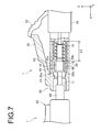
- FIG. 7 is a sectional view showing a state after the split sleeve is attached to the ferrule.
- FIG. 8 is a diagram for explaining the bundle fiber.
- FIG. 9A is a perspective view of a ferrule according to another embodiment.
- FIG. 9B is a front view of a ferrule according to another embodiment.
- FIG. 10A is a plan sectional view of a front housing according to another embodiment.
- FIG. 10B is a side sectional view of a front housing according to another embodiment.
- Non-Patent Document 1 the flange is divided into a plurality of parts and moved in the up-down direction and the left-right direction, the number of parts of the optical connector increases, and the structure becomes complicated. It is difficult to reduce the cost.
- An optical connector includes a ferrule, a plug frame, and an elastic member.
- the ferrule is provided with a flange on the outside, has a through hole in the inside, and is exposed from the resin coating at one end of an optical fiber including a glass fiber in the through hole and a resin coating covering the glass fiber.
- the glass fiber can be held.
- the plug frame is configured to accommodate the ferrule.
- the elastic member biases the ferrule along the central axis direction of the ferrule.
- the elastic member can hold the ferrule at a first position in the plug frame with a first length of the elastic member, and the ferrule with a second length shorter than the first length. It can be held in a second position within the frame.
- At least one of the ferrule and the plug frame has at least one tapered surface whose distance from the central axis of the ferrule decreases in the biasing direction of the elastic member.
- the height of the ferrule or the height or width of the plug frame gradually decreases in the urging direction, it becomes easy to insert the ferrule from the rear of the plug frame.
- the gap between the ferrule and the plug frame becomes smaller, which facilitates the positioning of the ferrule with respect to the plug frame.
- the at least one tapered surface has a first tapered surface and a second tapered surface.
- the first taper surface and the second taper surface are configured to face each other with the central axis of the ferrule interposed therebetween. Thereby, the rotation between the plug frame and the ferrule at the first position is more reliably suppressed.
- the flange of the ferrule has a polygonal shape in a sectional view.
- the flange of the ferrule has a quadrangular shape in cross section. This facilitates the manufacture of the ferrule with the flange.
- the ferrule is made of zirconia. As a result, it is possible to suppress reflection on the end surface of the ferrule as compared with a metal ferrule.
- the optical connector includes the optical fiber.
- the optical fiber is a multi-core fiber, a polarization maintaining fiber, or a bundle fiber.
- An optical connection structure includes (7) an optical connector assembly in which an optical fiber is incorporated in the optical connector, and an object to be connected to the optical connector assembly via a sleeve, It is an optical connection structure for optically connecting the optical fiber and the optical fiber in the connection target.
- the ferrule is floating relative to the plug frame when the ferrule is inserted into the sleeve and the ferrule is in the second position. As a result, the ferrule is positioned with respect to the plug frame and rotation is prevented until the optical connector assembly and the connection target are connected.
- the ferrule is held in the plug frame only through the elastic member, so that the connector can be used even when an external force is applied to the plug frame.
- the optical connection state by the optical fiber in the assembly and the optical fiber in the connection target can be maintained. Therefore, it is possible to provide an optical connection structure having a simple structure and easily maintaining the optical connection state.
- FIG. 1 is an external perspective view showing an optical connector 1 according to an aspect of the present disclosure with an optical fiber incorporated.
- FIG. 2 is a perspective view of the ferrule 10 included in the optical connector 1
- FIG. 3 is a perspective view of the front housing 21 that constitutes the plug frame 20 of the optical connector 1.
- 4A is a sectional view taken along the line AA of FIG. 3
- FIG. 4B is a sectional view taken along the line BB of FIG. 3
- FIG. 4C is a sectional view taken along the line CC of FIG. Is.
- FIG. 5 is a sectional view showing a state before the ferrule 10 is housed in the plug frame 20.
- an optical connector will be described as an example of an LC connector.
- the optical connector 1 includes a plug frame 20 that houses the ferrule 10, and a boot 34 that protects the optical fiber F is provided at the rear end of the plug frame 20.
- the ferrule 10 has a ferrule body 11 extending in the illustrated X-axis direction.
- the ferrule main body 11 is made of, for example, zirconia and has a cylindrical shape, and has a through hole inside the ferrule main body 11, and the glass fiber exposed from the resin coating of the tip portion (one end portion) of the optical fiber F is in the through hole.
- the optical fiber F is, for example, a multi-core fiber having a plurality of cores, and is inserted from the rear end 13 of the ferrule body 11, the front end surface is exposed from the front end 12, and the plurality of cores are provided at predetermined positions around the center axis of the ferrule 10.
- the direction of the axis of the through hole is represented by the X axis in the drawing.
- the direction of the through hole is also referred to as the optical axis direction of the optical fiber F.
- a flange 14 made of, for example, a metal is provided outside the ferrule body 11 at a substantially central position.
- the flange 14 has, for example, a substantially polygonal shape in cross section (substantially quadrangular shape in FIG. 2), and has an upper surface 15, a lower surface (flat surface) 16, a left side surface 17, and a right side surface 18 that form an outer peripheral surface of the flange 14.
- the upper surface 15 and the lower surface 16 are flat surfaces that face each other with the optical axis of the optical fiber F interposed therebetween and are parallel to each other with a predetermined distance in the Z-axis direction shown in the drawing.
- the left side surface 17 and the right side surface 18 are flat surfaces which are orthogonal to the upper surface 15 and the lower surface 16 and are opposed to each other with the optical axis of the optical fiber F interposed therebetween, and are parallel to each other with a predetermined distance in the Y axis direction shown in the drawing. Is.
- the boundary positions between the upper surface 15 and the left side surface 17 and the right side surface 18 and the boundary positions between the lower surface 16 and the left side surface 17 and the right side surface 18 are chamfered. If the upper surface 15 is provided with a mark (not shown) for indicating the reference of the rotational position, the ferrule 10 can be inserted into the plug frame 20 in the correct direction.
- the plug frame 20 has a square tubular front housing 21 extending in the illustrated X-axis direction.
- the front housing 21 is made of resin, for example, and has a rear end opening 24 that can receive the ferrule 10 with the flange 14 and a front end opening 23 that projects the front end 12 of the ferrule body 11 described in FIG.
- a flexible latch arm 22 is provided on the outer peripheral surface of the front housing 21.
- the inside of the front housing 21 has a clearance portion 25 closest to the rear end opening 24 (negative direction of the X-axis in the drawing, the same applies hereinafter), and rotation regulation in front of the clearance portion 25.
- the portion 26 is partitioned from the opening 27 of the rotation restricting portion 26, which has a substantially rectangular tubular shape in the front.
- the clearance portion 25 does not engage with the flange 14 of the ferrule 10 and has an upper surface 25a, a lower surface 25b, a left side surface 25c, and a right side surface 25d, as shown in FIGS. 4A to 4C.
- the upper surface 25a and the lower surface 25b are parallel to each other with a predetermined distance in the Z-axis direction shown, and the left side surface 25c and the right side surface 25d are parallel to each other with a predetermined distance in the Y-axis direction shown.
- the clearance portion 25 is an internal space in the shape of a rectangular tube including the upper surface 25a, the lower surface 25b, the left side surface 25c, and the right side surface 25d
- the distance from the upper surface 25a to the lower surface 25b is greater than the thickness of the flange 14 (the distance between the upper surface 15 and the lower surface 16).
- the rotation restricting portion 26 includes a taper surface (first taper surface 26a, second taper surface 26b) that restricts the rotation of the ferrule 10, a left side surface 26c, and a right side surface 26d.
- the first tapered surface 26a and the second tapered surface 26b which are tapered surfaces, face each other with a distance in the illustrated Z-axis direction across the optical axis, and the left side surface 26c and the right side surface 26d are opposed to each other in the illustrated Y axis direction. They are parallel to each other at a predetermined distance.
- the distance between the first taper surface 26a and the second taper surface 26b and the optical axis decreases in the biasing direction of the coil spring 19.
- the coil spring 19 will be described later.
- the distance in the Z-axis direction between the front end of the first tapered surface 26a and the front end of the second tapered surface 26b is smaller than the thickness of the flange 14 of the ferrule 10 (the distance between the upper surface 15 and the lower surface 16).
- the distance in the Z-axis direction between the rear end of the first tapered surface 26a and the rear end of the second tapered surface 26b is larger than the thickness of the flange 14 of the ferrule 10 (the distance between the upper surface 15 and the lower surface 16).
- the distance between the upper and lower surfaces in the front housing 21 is gradually shortened from the clearance portion 25 toward the rotation restricting portion 26, so that the ferrule 10 can be easily inserted from the rear of the front housing 21.
- the ferrule 10 can be easily positioned in the front housing 21.
- the plug frame 20 has a rear housing 31 behind the front housing 21.
- the rear housing 31 is made of resin, for example, and has a cylindrical spring accommodating portion 33 capable of accommodating the rear end portion of the ferrule 10 and the coil spring (elastic member) 19.
- the coil spring 19 is disposed behind the ferrule 10 and contacts the rear end of the flange 14 to urge the ferrule 10 forward (the positive direction of the X axis in the drawing, the same applies hereinafter).
- a clip 32 that can be engaged with the latch arm 22 is provided on the outer peripheral surface of the rear housing 31.
- the rear end portion of the ferrule 10 and the coil spring 19 are housed in the rear housing 31, and the front end portion of the ferrule 10 is inserted into the front housing 21.
- the flange 14 can be placed on the lower surface 25b of the front housing 21 at the position of the clearance portion 25.
- the front housing 21 is latched by the rear housing 31.
- the flange 14 is pushed forward by the biasing force of the coil spring 19, and the upper surface 15 of the flange 14 is along the first tapered surface 26a of the front housing 21, or the lower surface 16 of the flange 14 is the first taper surface of the front housing 21. 2
- the front end 12 of the ferrule 10 projects from the front housing 21 when it comes into contact with the second taper surface 26 b (hereinafter, the position of the ferrule 10 in the plug frame 20 at this time is referred to as “first position P1”).
- first position P1 the position of the ferrule 10 in the plug frame 20 at this time.
- the flange 14 is sandwiched between the first tapered surface 26a and the second tapered surface 26b of the front housing 21, and the flange 14 is restricted from rotating with respect to the front housing 21 at the first position P1 and in the Z-axis direction. It is held in a difficult state.
- the length of the coil spring 19 at this time is referred to as a first length L1.
- the optical connection structure includes an optical connector 1 and another optical connector 1 ′, and a split sleeve (sleeve) 40 is used to connect the optical fiber F on the optical connector 1 side.
- an optical fiber F′ (not shown) on the optical connector 1′ side is optically connected.
- the optical fiber F′ is also a multi-core fiber having a plurality of cores, and is fixed to the ferrule 10′ in a state where the plurality of cores are arranged at predetermined positions around the center axis of the ferrule 10′.
- optical connector (connection target) 1' is not shown in a cross-sectional view, it has the same structure as the optical connector 1 and holds the optical fiber F'in the plug frame 20' and the ferrule 10' or the ferrule 10'. Has an elastic member (not shown) for urging.
- the split sleeve 40 has an inner diameter substantially equal to the diameter of the ferrules 10 and 10', or slightly smaller than the diameter of the ferrules 10 and 10'.
- the split sleeve 40 has a slit (not shown), and the slit can be widened to increase the inner diameter.
- the split sleeve 40 may be incorporated in an adapter (a component that connects connectors of the same type or different types, for example, http://www.optigate.jp/products/connector/adapter.html).
- the ferrule 10 shown in FIG. 6 is inserted from one end of the split sleeve 40, the ferrule 10' is inserted from the other end of the split sleeve 40, and the end face of the optical fiber F on the ferrule 10 side and the optical fiber F on the ferrule 10' side are inserted.
- the end face of the' is brought into surface contact with the split sleeve 40 (also referred to as connector connection).
- FIG. 7 when the split sleeve 40 enters the front housing 21 and the ferrule 10 moves to the second position P2 rearward from the first position P1 (that is, the coil spring 19 moves from the first length L1).
- the flange 14 moves rearward against the biasing force of the coil spring 19, so that the taper surface (the first taper surface 26a and the second taper surface 26b) of the front housing 21 is formed. ) And the upper surface 15 and the lower surface 16 of the flange 14 are released. At this time, the ferrule 10 is held at the second position P2 in the plug frame 20 by the split sleeve 40 and the coil spring 19.
- the ferrule 10 is not positioned with respect to the front housing 21, is in a floating state, and can move in any of the X axis, Y axis, and Z axis directions. Therefore, it is possible to rotate around the optical axis together with the optical fiber F'on the optical connector 1'side.
- the upper surface 15 and the lower surface 16 of the flange 14 and the taper surface (first taper surface) of the flange 14 are connected until the optical connector 1 and the optical connector 1′ are connected (until the ferrule 10 is moved from the front to the rear). 26a and the second tapered surface 26b) are in contact with each other, so that the ferrule 10 is positioned with respect to the front housing 21 and rotation is prevented. Therefore, by allowing the plug frame 20 to face the plug frame 20', it is possible to accurately face each of the plurality of cores included in the optical fiber F and each of the plurality of cores included in the optical fiber F'.
- the upper surface 15 and the lower surface 16 of the flange 14 and the tapered surface (first taper) of the front housing 21 After connecting the optical connector 1 and the optical connector 1 ′ (after moving the ferrule 10 rearward: when connecting the connector), the upper surface 15 and the lower surface 16 of the flange 14 and the tapered surface (first taper) of the front housing 21. Since the contact state between the surface 26a and the second taper surface 26b) is released and the ferrule 10 is floated with respect to the front housing 21, even if an external force is applied to the front housing 21 or the rear housing 31, the external force is applied to the ferrule 10. Not transmitted, the optical connection state by the two optical fibers F and F′ can be maintained.
- the upper surface 15 and the lower surface 16 of the flange 14 and the taper surfaces (the first taper surface 26a and the second taper surface 26b) of the front housing 21 are in a state where the ferrule 10 is positioned with respect to the front housing 21 and a floating state.
- This is achieved only by installation, the number of parts of the optical connector 1 is small, and the structure of the optical connector 1 is simple. As a result, it is possible to provide an optical connection structure having a simple structure and easily maintaining the optical connection state.
- the present disclosure is not limited to this example, and may have the tapered surface of the front housing 21 on the side surface. That is, the surface serving as the first tapered surface 26a and the surface serving as the second tapered surface 26b may be simply flat surfaces, the left side surface 26c may be the first tapered surface, and the right side surface 26d may be the second tapered surface.
- the optical connector has been described as an example of the LC connector in the embodiment, the present disclosure can be applied to other types of optical connectors including, for example, the SC connector and the MU connector.
- the optical fiber F has been described as an example of the multi-core fiber.
- the optical fiber of the present disclosure may be, for example, a single mode fiber, a polarization maintaining fiber, or a bundle fiber.
- the multi-core fiber, the polarization-maintaining fiber, and the bundle fiber are optical fibers that require adjustment of the rotation angle around the central axis when optically connected.
- a bundle fiber is a fiber in which a plurality of single-core fibers are collected for optical connection with a multi-core fiber.
- a single-core fiber having a glass diameter of 125 ⁇ m is chemically etched at its tip to be thinned to a glass diameter of, for example, 45 ⁇ m, and a plurality of (for example, 7) adhesives are used as shown in FIG. And put them all together in the ferrule 10.
- the cores can be arranged such that the distance between them is 45 ⁇ m.
- optical connector 1 including the ferrule 10 having the flange 14 having a substantially rectangular cross section and the plug frame 20 having the front housing 21 having the tapered surface
- the optical connector of the present disclosure may have a tapered surface on the ferrule and the inside of the front housing of the plug frame may be a flat surface, which will be specifically described below.
- the upper surface 15 of the flange 14 of the ferrule 10 has a flat surface 15a and a first tapered surface 15b on the biasing direction side of the flat surface 15a.
- the lower surface 16 of the flange 14 of the ferrule 10 also has a flat surface 16a and a second tapered surface 16b on the biasing direction side of the flat surface 16a.
- the flat surface 15a and the flat surface 16a face each other across the optical axis of the optical fiber F, and are parallel to each other with a predetermined distance in the Z-axis direction shown in the drawing.
- the first taper surface 15b and the second taper surface 16b face each other with the optical axis in between, and the distance between the first taper surface 15b and the second taper surface 16b and the optical axis decreases in the urging direction. ing.
- the distance in the Z-axis direction between the rear end of the first tapered surface 15b and the rear end of the second tapered surface 16b is larger than the distance in the Z-axis direction between the flat surfaces 15a and 16a.
- the rotation restricting portion 26 of the front housing 21 has the tapered surface (the first tapered surface 26a and the second tapered surface 26b) has been described. Since it has a surface, the front housing 21 has a flat surface instead of a tapered surface. Specifically, as shown in FIGS. 10A and 10B, the rotation restricting portion 26 has an upper surface 261a, a lower surface 261b, a left side surface 26c, and a right side surface 26d.
- the upper surface 261a and the lower surface 261b are parallel to each other with a predetermined distance in the Z-axis direction shown, and the left side surface 25c and the right side surface 25d are parallel to each other with a predetermined distance in the Y-axis direction shown.
- the distance in the Z-axis direction between the upper surface 261a and the lower surface 261b is larger than the distance in the Z-axis direction between the front end of the first tapered surface 26a and the front end of the second tapered surface 26b, and the distance between the first tapered surface 26a and It is smaller than the distance in the Z-axis direction between the rear end and the rear end of the second tapered surface 26b.
- the ferrule 10 is inserted from the rear of the front housing 21. It is easy to position the ferrule 10 on the front housing 21.
Landscapes
- Physics & Mathematics (AREA)
- General Physics & Mathematics (AREA)
- Optics & Photonics (AREA)
- Mechanical Coupling Of Light Guides (AREA)
Priority Applications (4)
| Application Number | Priority Date | Filing Date | Title |
|---|---|---|---|
| JP2020566414A JPWO2020149262A1 (ja) | 2019-01-15 | 2020-01-14 | 光コネクタおよび光接続構造 |
| CN202080008439.2A CN113272699A (zh) | 2019-01-15 | 2020-01-14 | 光连接器及光连接构造 |
| US17/367,810 US11940655B2 (en) | 2019-01-15 | 2021-07-06 | Optical connector and optical connection structure |
| JP2024048231A JP2024075729A (ja) | 2019-01-15 | 2024-03-25 | 光コネクタの製造方法 |
Applications Claiming Priority (2)
| Application Number | Priority Date | Filing Date | Title |
|---|---|---|---|
| JP2019004071 | 2019-01-15 | ||
| JP2019-004071 | 2019-01-15 |
Related Child Applications (1)
| Application Number | Title | Priority Date | Filing Date |
|---|---|---|---|
| US17/367,810 Continuation US11940655B2 (en) | 2019-01-15 | 2021-07-06 | Optical connector and optical connection structure |
Publications (1)
| Publication Number | Publication Date |
|---|---|
| WO2020149262A1 true WO2020149262A1 (ja) | 2020-07-23 |
Family
ID=71613894
Family Applications (1)
| Application Number | Title | Priority Date | Filing Date |
|---|---|---|---|
| PCT/JP2020/000878 Ceased WO2020149262A1 (ja) | 2019-01-15 | 2020-01-14 | 光コネクタおよび光接続構造 |
Country Status (4)
| Country | Link |
|---|---|
| US (1) | US11940655B2 (enExample) |
| JP (2) | JPWO2020149262A1 (enExample) |
| CN (1) | CN113272699A (enExample) |
| WO (1) | WO2020149262A1 (enExample) |
Cited By (4)
| Publication number | Priority date | Publication date | Assignee | Title |
|---|---|---|---|---|
| JPWO2022131169A1 (enExample) * | 2020-12-18 | 2022-06-23 | ||
| JPWO2022181548A1 (enExample) * | 2021-02-26 | 2022-09-01 | ||
| WO2023281979A1 (ja) * | 2021-07-07 | 2023-01-12 | 住友電気工業株式会社 | 光コネクタ |
| US12535642B2 (en) | 2022-07-27 | 2026-01-27 | Sumitomo Electric Industries, Ltd. | Optical fiber bundle connector and method of manufacturing optical fiber bundle connector |
Families Citing this family (2)
| Publication number | Priority date | Publication date | Assignee | Title |
|---|---|---|---|---|
| EP4139725B1 (en) * | 2020-04-23 | 2025-04-02 | US Conec, Ltd | Miniature multi-fiber ferrule |
| US12321017B2 (en) | 2020-04-23 | 2025-06-03 | Us Conec Ltd. | Fiber optic ferrule and fiber optic ferrule receiver |
Citations (4)
| Publication number | Priority date | Publication date | Assignee | Title |
|---|---|---|---|---|
| JPH0894879A (ja) * | 1994-09-27 | 1996-04-12 | Nippon Telegr & Teleph Corp <Ntt> | 偏波保持ファイバ用光コネクタ |
| JP2002318324A (ja) * | 2001-04-20 | 2002-10-31 | Furukawa Electric Co Ltd:The | 光コネクタフェルール用ハウジング、ハウジング付き光コネクタフェルール、光コネクタ |
| US20020191919A1 (en) * | 1998-12-28 | 2002-12-19 | Computer Crafts, Inc. | Fiber optic connectors |
| WO2016103821A1 (ja) * | 2014-12-24 | 2016-06-30 | 日本航空電子工業株式会社 | コネクタ内蔵プラグ |
Family Cites Families (2)
| Publication number | Priority date | Publication date | Assignee | Title |
|---|---|---|---|---|
| JP3305149B2 (ja) * | 1995-02-20 | 2002-07-22 | 本多通信工業株式会社 | 光コネクタ |
| US20020186931A1 (en) | 2001-04-20 | 2002-12-12 | Koji Seo | Housing for optical connector and optical connector |
-
2020
- 2020-01-14 WO PCT/JP2020/000878 patent/WO2020149262A1/ja not_active Ceased
- 2020-01-14 JP JP2020566414A patent/JPWO2020149262A1/ja active Pending
- 2020-01-14 CN CN202080008439.2A patent/CN113272699A/zh active Pending
-
2021
- 2021-07-06 US US17/367,810 patent/US11940655B2/en active Active
-
2024
- 2024-03-25 JP JP2024048231A patent/JP2024075729A/ja active Pending
Patent Citations (4)
| Publication number | Priority date | Publication date | Assignee | Title |
|---|---|---|---|---|
| JPH0894879A (ja) * | 1994-09-27 | 1996-04-12 | Nippon Telegr & Teleph Corp <Ntt> | 偏波保持ファイバ用光コネクタ |
| US20020191919A1 (en) * | 1998-12-28 | 2002-12-19 | Computer Crafts, Inc. | Fiber optic connectors |
| JP2002318324A (ja) * | 2001-04-20 | 2002-10-31 | Furukawa Electric Co Ltd:The | 光コネクタフェルール用ハウジング、ハウジング付き光コネクタフェルール、光コネクタ |
| WO2016103821A1 (ja) * | 2014-12-24 | 2016-06-30 | 日本航空電子工業株式会社 | コネクタ内蔵プラグ |
Cited By (7)
| Publication number | Priority date | Publication date | Assignee | Title |
|---|---|---|---|---|
| JPWO2022131169A1 (enExample) * | 2020-12-18 | 2022-06-23 | ||
| EP4266097A4 (en) * | 2020-12-18 | 2024-05-22 | Sumitomo Electric Industries, Ltd. | Optical connector and optical connection structure |
| JP7786395B2 (ja) | 2020-12-18 | 2025-12-16 | 住友電気工業株式会社 | 光コネクタ及び光接続構造 |
| JPWO2022181548A1 (enExample) * | 2021-02-26 | 2022-09-01 | ||
| WO2022181548A1 (ja) * | 2021-02-26 | 2022-09-01 | 住友電工オプティフロンティア株式会社 | 光コネクタ |
| WO2023281979A1 (ja) * | 2021-07-07 | 2023-01-12 | 住友電気工業株式会社 | 光コネクタ |
| US12535642B2 (en) | 2022-07-27 | 2026-01-27 | Sumitomo Electric Industries, Ltd. | Optical fiber bundle connector and method of manufacturing optical fiber bundle connector |
Also Published As
| Publication number | Publication date |
|---|---|
| US20210333483A1 (en) | 2021-10-28 |
| JPWO2020149262A1 (ja) | 2021-11-25 |
| JP2024075729A (ja) | 2024-06-04 |
| CN113272699A (zh) | 2021-08-17 |
| US11940655B2 (en) | 2024-03-26 |
Similar Documents
| Publication | Publication Date | Title |
|---|---|---|
| WO2020149262A1 (ja) | 光コネクタおよび光接続構造 | |
| US11054586B2 (en) | Optical connector and optical connection structure | |
| JP7047314B2 (ja) | 光コネクタおよび光接続構造 | |
| JP7027781B2 (ja) | 光コネクタおよび光接続構造 | |
| JP6354208B2 (ja) | 光結合部材 | |
| JP2024075729A5 (enExample) | ||
| JP2016095410A (ja) | グリンレンズアレイ、レンズ付きコネクタ、及びレンズ付きコネクタシステム | |
| US9618705B2 (en) | Receptacle connector | |
| JP7444076B2 (ja) | 光コネクタの製造方法 | |
| WO2016076272A1 (ja) | 光コネクタ結合システム | |
| JP7786395B2 (ja) | 光コネクタ及び光接続構造 | |
| US20250224571A1 (en) | Optical connector | |
| JP2021119363A (ja) | 光コネクタおよび光接続構造 | |
| US20260016643A1 (en) | Optical connector, ferrule, and optical coupling structure | |
| WO2025239152A1 (ja) | 光コネクタ | |
| CN121399515A (zh) | 保持构件、光连接器以及光连接组件 | |
| WO2019150703A1 (ja) | 光コネクタレセプタクル及び光コネクタレセプタクルの製造方法 | |
| JP2003029091A (ja) | 多心用光ファイバコネクタの構造 |
Legal Events
| Date | Code | Title | Description |
|---|---|---|---|
| 121 | Ep: the epo has been informed by wipo that ep was designated in this application |
Ref document number: 20740795 Country of ref document: EP Kind code of ref document: A1 |
|
| ENP | Entry into the national phase |
Ref document number: 2020566414 Country of ref document: JP Kind code of ref document: A |
|
| NENP | Non-entry into the national phase |
Ref country code: DE |
|
| 122 | Ep: pct application non-entry in european phase |
Ref document number: 20740795 Country of ref document: EP Kind code of ref document: A1 |