WO2020149246A1 - 培養容器、培養方法、及び培養装置 - Google Patents
培養容器、培養方法、及び培養装置 Download PDFInfo
- Publication number
- WO2020149246A1 WO2020149246A1 PCT/JP2020/000776 JP2020000776W WO2020149246A1 WO 2020149246 A1 WO2020149246 A1 WO 2020149246A1 JP 2020000776 W JP2020000776 W JP 2020000776W WO 2020149246 A1 WO2020149246 A1 WO 2020149246A1
- Authority
- WO
- WIPO (PCT)
- Prior art keywords
- culture
- culture container
- medium
- recesses
- spheres
- Prior art date
- Legal status (The legal status is an assumption and is not a legal conclusion. Google has not performed a legal analysis and makes no representation as to the accuracy of the status listed.)
- Ceased
Links
Images

Classifications
-
- C—CHEMISTRY; METALLURGY
- C12—BIOCHEMISTRY; BEER; SPIRITS; WINE; VINEGAR; MICROBIOLOGY; ENZYMOLOGY; MUTATION OR GENETIC ENGINEERING
- C12M—APPARATUS FOR ENZYMOLOGY OR MICROBIOLOGY; APPARATUS FOR CULTURING MICROORGANISMS FOR PRODUCING BIOMASS, FOR GROWING CELLS OR FOR OBTAINING FERMENTATION OR METABOLIC PRODUCTS, i.e. BIOREACTORS OR FERMENTERS
- C12M1/00—Apparatus for enzymology or microbiology
Definitions
- the present invention relates to a cell culture technique, and particularly to a technique for improving the efficiency of sphere creation and the like.
- the migration of spheres frequently occurs when using a culture bag with shallow wells, but it is preferable to use a culture bag with shallow wells in order to properly perform medium exchange. That is, in the case of using a culture bag having a shallow well having a well depth of less than 500 ⁇ m, the movement of the sphere generally occurs unless the velocity (flow rate) of feeding the medium is 0.1 mL/min or less. Therefore, there is a problem that it takes a long time to completely discharge the medium from the culture bag. For example, when the amount of medium in the culture bag is 10 mL, it takes 100 minutes to discharge at a flow rate of 0.1 mL/min, which may cause damage to cells.
- spheres for research are being prepared by using a culture container such as a rigid microwell plate.
- a culture container such as a rigid microwell plate.
- A4 about 600 cm 2
- the culture bag is filled with 120 ml to 600 ml of the medium.
- the flow rate of the medium is set to 1 mL/min to 10 mL/min, it is possible to discharge the medium without causing movement of spheres.
- the flow rate of the medium is 0.1 mL/min or less. Therefore, for example, when the amount of the medium is 60 mL, the medium is It took 10 hours to discharge, and it was difficult to put into practical use.
- the inventors of the present invention have conducted diligent research to make at least a part of the side wall of the well substantially vertical even in a culture container having a shallow well having a depth of about 50 to 500 ⁇ m, and a vertical direction of the substantially vertical portion.
- the present invention has been completed by finding that by making the length of the sphere larger than half the maximum diameter of the sphere, it is possible to prevent the movement of the sphere even when the medium is fed at a flow rate of 1 mL/min or more in the medium exchange.
- Patent Document 1 can be cited as a prior document that describes a culture container including a well in which at least a part of the side wall is substantially vertical.
- Patent Document 1 discloses a culture vessel having a funnel-shaped bottom surface with an angle of 120 degrees or less, a hemispherical shape with a radius of curvature of 10 mm or less, or a shape in which the central portion of the bottom surface is a flat surface.
- these culture vessels are intended to form spheres in a rigid culture vessel, and cannot solve the above-mentioned problems in the case of feeding the medium to the culture bag.
- the liquid thickness of the medium is 2 mm or more, it is possible to discharge the medium without causing the movement of the spheres even if the flow rate of the medium is 1 mL/min. If it is 1 mm or less, the movement of the sphere will occur unless the flow rate of the medium is slowed down to about 0.1 mL/min. Further, when the liquid thickness of the medium was 0.5 mm or less, the flow rate of the medium had to be 0.05 mL/min or less.
- the present invention has been made in view of the above circumstances, and in a culture container having a culture part in which a plurality of recesses for accommodating an object to be cultured such as spheres is formed, a medium is flown at a flow rate of 1 mL/min or more.
- An object of the present invention is to provide a culture container, a culture method, and a culture device capable of preventing the movement of spheres or the like between recesses even when liquid is fed.
- the culture container of the present invention is a culture container having a culture part in which a plurality of recesses for accommodating spheres are formed, and at least one port is provided, and the depth of the recesses is provided. Is 50 to 500 ⁇ m, at least part of the side wall of the recess is substantially vertical, and the vertical length of the substantially vertical portion of the side wall is longer than half the maximum diameter of the sphere.
- the culture method of the present invention is a method of controlling the flow rate of the medium by injecting the medium from one port and discharging the medium from the other port using the above culture container.
- the culture apparatus of the present invention is provided with a pressing plate in contact with the upper surface of the culture container, the culture container is pressed by the pressing plate, the pressing plate, the injection or discharge of the medium to the culture container With this, it is movable in the vertical direction.
- a culture container having a culture part having a plurality of recesses for accommodating an object to be cultured such as spheres, even if the medium is fed at a flow rate of 1 mL/min or more, It is possible to provide a culture container, a culture method, and a culture device capable of preventing the movement of spheres and the like.
- FIG. 3 is a view showing a micrograph of a culture part of the culture container prepared in Example 1.
- FIG. 3 is a view showing a micrograph showing a state in which resin beads are placed in the culture container prepared in Example 1 to feed a medium.
- FIG. 3 is a view showing a micrograph showing a state where iPS cell spheres are housed in the culture container prepared in Example 1.
- FIG. 5 is a view showing a micrograph showing a state in which T cells are accommodated in the culture container created in Example 2.
- the culture container 10 of the present embodiment is a culture container having a culture part 11 in which a plurality of recesses (wells) for accommodating an object to be cultured such as a sphere is formed.
- Two ports 13 are provided.
- a tube 14 is connected to the port 13 so that the medium 1 is injected into the culture container 10 and the medium 1 is discharged from the culture container 10 by a pump or the like (not shown) arranged in the tube 14. Has become.
- the culture container 10 is made of a soft packaging material, is formed in a bag shape, and has a top plate portion 12.
- the distance (liquid thickness L) between the culture section 11 and the top plate section 12 is changed according to the amount of the medium 1 injected into the culture container 10.
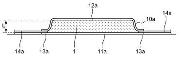
- FIG. 1 a modified example of the culture container 10 of the present embodiment is shown in FIG.
- the liquid thickness of the culture medium 1 in the culture container 10a can be made more uniform, and all the recesses can be brought into contact with the installation surface in parallel. This makes it possible to reduce the difference in the proliferative property of the culture object and the variation in the number of cells at the time of cell seeding.
- Other configurations are similar to those of the culture container 10 shown in FIG.
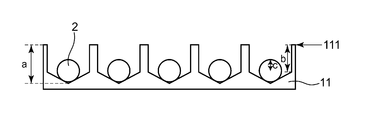
- the side wall of the plurality of recesses in the culture section 11 is formed in a substantially vertical shape.
- the culture object 2 is accommodated in these recesses, and the vertical length (b) of the substantially vertical portion of the side wall is longer than half the maximum diameter (c) of the culture object 2.
- the shape of the region in which the side wall of the recess is substantially vertical can be, for example, a columnar shape, a square columnar shape, or the like.
- the arrangement of the plurality of recesses in the culture section 11 may be, for example, a staggered pattern or a lattice pattern.
- the depth (a) of the recess is preferably 50 to 500 ⁇ m. This is because if the depth (a) of the recess is larger than 500 ⁇ m, it may be difficult to sufficiently replace the medium in the recess even when the medium 1 is fed to the culture container 10. Further, it is because the culture container having the recesses deeper than 500 ⁇ m has a high difficulty in processing.
- one sphere can be formed by aggregating about 200 to several thousand single cells (single cells).
- the size of the sphere thus formed is about 50 ⁇ m to 100 ⁇ m for a small one, and about 200 ⁇ m to 300 ⁇ m for a large one. Therefore, the depth (a) of the recess is preferably 75 to 500 ⁇ m, and more preferably 100 to 500 ⁇ m. In addition, the depth (a) of the recess is preferably 100 to 400 ⁇ m, and more preferably 100 to 250 ⁇ m.
- the shape of the bottom of the recess is not particularly limited, but when the culture object 2 is a sphere, in order to facilitate aggregation of the single cells and to favorably form the sphere, a cone shape, a hemisphere shape Or, it is preferable that the shape is rounded.
- the depth (a) of the recess is preferably 5 to 50 ⁇ m. This is because the size of the single cell is about 6 ⁇ m to 15 ⁇ m, and often about 10 ⁇ m. Therefore, in this case, the depth (a) of the recess is preferably 6 to 50 ⁇ m, and more preferably 10 to 50 ⁇ m. Further, the depth (a) of the recess is preferably 10 to 40 ⁇ m, and more preferably 10 to 25 ⁇ m.
- the shape of the opening of the recess is not particularly limited, and may be circular or rectangular such as square. Further, the width of the opening of the recess can be appropriately set according to the size of the culture object 2. For example, when the culture object 2 is a sphere, the lower limit of the diameter of the circle or the inscribed circle of the opening of the recess is 60 ⁇ m or more, 70 ⁇ m or more, 80 ⁇ m or more, 90 ⁇ m or more, 100 ⁇ m or more, 110 ⁇ m or more, 120 ⁇ m or more, 150 ⁇ m The above may be applied.
- the upper limit of the diameter of the circle or the inscribed circle of the opening of the recess may be 1 mm or less, 900 ⁇ m or less, 800 ⁇ m or less, 700 ⁇ m or less, 500 ⁇ m or less.
- the lower limit of the diameter of the circle or the inscribed circle of the opening of the recess may be 5 ⁇ m or more, 6 ⁇ m or more, 8 ⁇ m or more.
- the upper limit of the diameter of the circle or the inscribed circle of the opening of the recess may be 50 ⁇ m or less, 40 ⁇ m or less, 30 ⁇ m or less.
- the culture container 10 of the present embodiment preferably has two ports 13, and these ports 13 are provided in the vertical direction (parallel to the bottom surface) with respect to the substantially vertical portion of the side wall of the recess, and both ends of the culture container are provided. It is preferable that they are provided facing each other.
- the flow rate of the medium 1 is preferably controlled to 1 mL/min or more, more preferably 3 mL/min or more, further preferably 5 mL/min or more, and more preferably 10 mL/min or more. It is even more preferred to control.
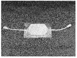
- FIG. 1 A photograph of such a culture container of this embodiment is shown in FIG. Further, a micrograph of a part of the culture part of the culture container is shown in FIG.
- This culture container is provided with about 50,000 recesses in the culture section, the depth of the recesses is 250 ⁇ m, the vertical length of the substantially vertical portion of the side wall of the recesses is 170 ⁇ m, and the opening of the recesses is The shape is square, the diameter of the inscribed circle is 260 ⁇ m, the bottom of the recess is pyramidal, and the spacing between the openings of the recess is 40 ⁇ m.
- two ports are provided so as to face each other at both ends of the culture container in a direction perpendicular to a substantially vertical portion of the side wall of the recess.
- a sphere having a diameter of 200 ⁇ m is put in the recess of the culture container, the medium is injected from one port of the culture container, the medium is discharged from the other port, and the flow rate of the medium is 3 mL/min or the like. Controlled to. As a result, it was not observed that the resin beads jumped out of the recess and moved to other recesses.
- the flow rate of the medium in the present embodiment can be calculated from the amount of medium to be injected and discharged, but the actual flow rate of the medium in the culture container 10 varies depending on the location in the culture container 10 and the change in the liquid thickness. .. That is, since the flow velocity in the vicinity of the port 13 is the highest in the culture container 10, it is important that the culture object 2 does not move from the concave portion in this region. Further, as the liquid thickness is reduced by pressing the top plate portion 12, the flow velocity becomes faster. Therefore, even in such a case, it is important that the culture object 2 does not move from the recess.
- a polyolefin resin such as polyethylene or polypropylene can be preferably used.
- examples thereof include polyethylene, ethylene- ⁇ -olefin copolymers, ethylene-vinyl acetate copolymers, ethylene-acrylic acid or methacrylic acid copolymers, and ionomers using metal ions.
- polyolefin, styrene-based elastomer, polyester-based thermoplastic elastomer, silicone-based thermoplastic elastomer, silicone resin and the like can also be used.
- silicone rubber soft vinyl chloride resin, polybutadiene resin, ethylene-vinyl acetate copolymer, chlorinated polyethylene resin, polyurethane-based thermoplastic elastomer, polyester-based thermoplastic elastomer, silicone-based thermoplastic elastomer, styrene-based elastomer, for example, SBS (styrene/butadiene/styrene), SIS (styrene/isoprene/styrene), SEBS (styrene/ethylene/butylene/styrene), SEPS (styrene/ethylene/propylene/styrene), polyolefin resin, fluorine resin, etc. Good.
- SBS styrene/butadiene/styrene
- SIS styrene/isoprene/styrene
- SEBS styrene/ethylene/butylene/styrene
- the culture object 2 is a sphere
- a cell adhesion inhibitor cell low adhesion treatment agent
- phospholipid polymer, polyvinyl alcohol derivative, phospholipid/polymer complex, polyhydroxyethyl methacrylate, polyvinyl alcohol, agarose, chitosan, polyethylene glycol, albumin and the like can be used. Also, these may be used in combination.
- the culture container 10 of the present embodiment is used for a step of forming a sphere, a step of culturing and proliferating while maintaining a sphere state, a step of inducing differentiation in a sphere state, and the like.
- a method of forming spheres using differentiated cells obtained from iPS cells, ES cells, and other stem cells that have already undergone a differentiation-inducing step, or a method in which differentiation-induced cells are cryopreserved and thawed again to form spheres It can also be used in methods and the like.
- a top plate protrusion is provided inside the culture container 10 so that the width of the top protrusion is smaller than the width of the opening of the recess and the height of the top protrusion is reduced.
- the diameter is made smaller than the minimum diameter of the culture object 2 and a gap is formed between the top surface 111 and the top plate portion 12 when the top plate protrusion contacts a part of the top surface 111 of the culture portion 11. Is also preferable.
- the culture container 10 of the present embodiment has such a configuration, due to the shape of the recess of the culture section 11, it is possible to prevent the movement of the sphere between the recesses even when the medium is fed at a flow rate of 1 mL/min or more.
- the top plate protrusion is brought into contact with a part of the upper end surface 111 to form a gap smaller than the size of the culture object 2 as the upper end surface 111. It can be in a state of being formed on the top plate portion 12. This makes it possible to prevent the movement of the culture object such as the sphere while allowing the liquid matter such as the medium to pass through the gap.
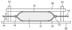
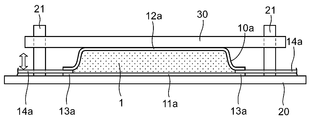
- the culture device of the present embodiment includes a culture container 10, a loading table 20, guide pins 21, and a pressing plate 30.
- FIG. 6 shows an example in which the culture container 10a shown in FIG. 2 is arranged in this culture device.
- the culture container 10 is arranged on the loading table 20, and the pressing plate 30 is arranged in contact with the upper surface thereof.
- Guide pins 21 are provided upright at four corners of the loading table 20, and the pressing plate 30 is supported by these guide pins 21 so as to be vertically movable.
- the culture container 10 can be fixed so as to be pressed with a constant pressure by the weight of the pressing plate 30.
- a spring material can be installed on the guide pin 21 and the pressing plate 20 can be appropriately pressed against the culture container 10.
- the pressing plate 30 can be moved in the vertical direction as the culture medium is poured into or discharged from the culture container 10. According to the culture apparatus of the present embodiment, with such a configuration, the flow rate of the medium in the culture container 10 can be controlled more appropriately.
- the culture container having the culture part having a plurality of recesses for accommodating the culture object such as the sphere, the medium It is possible to prevent the movement of spheres or the like between the concave portions even when the solution is sent at a flow rate of 1 mL/min or more.
- Example 1 As the culture container of Example 1, the depth of the recess was 250 ⁇ m, the vertical length of the substantially vertical portion of the side wall of the recess was 170 ⁇ m, the shape of the opening of the recess was square, and the inscribed circle was The diameter was 260 ⁇ m, the bottom of the recess was pyramid-shaped, the spacing between the openings of the recess was 40 ⁇ m, and the culture section was equipped with 50,000 recesses. A micrograph of the prepared culture container is shown in FIG. The photograph on the left side of the figure shows a part of the culture vessel, and the photograph on the right is an enlarged part thereof. In addition, a simulated sphere and a real sphere were prepared as culture objects. The pseudo sphere is a resin bead having a uniform diameter of 200 ⁇ m, and the actual sphere is an iPS sphere having a diameter of about 80 ⁇ m.
- FIG. 8 shows a micrograph of the state in which the resin beads are placed and the medium is being sent.
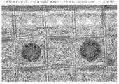
- FIG. 9 shows a micrograph of the culture container in a state in which the iPS cell spheres are contained.
- the pump attached to the port was driven to feed the medium at three flow rates of 0.2 mL/min, 1 mL/min, and 3 mL/min, and a microscope was used to check whether the spheres had moved. It was confirmed by visual observation. As a result, in the culture container of Example 1, spheres did not move at all three flow rates of both the artificial sphere and the real sphere.
- the artificial spheres and the real spheres were separately injected into the culture container, dispersed throughout, and housed in the recess. Then, the pump attached to the port was driven to feed the medium at three flow rates of 0.2 mL/min, 1 mL/min, and 3 mL/min, and a microscope was used to check whether the spheres had moved. It was confirmed by visual observation. As a result, in the culture container of Reference Example 1, spheres did not move at all three flow rates of both the artificial sphere and the real sphere.
- Comparative Example 1 As the culture vessel of Comparative Example 1, the depth of the recess was 250 ⁇ m, the sidewall of the recess was rounded, the shape of the opening of the recess was circular, the diameter was 1 mm, and the distance between the openings of the recess was Was 50 ⁇ m, and a culture part having 4000 recesses was prepared. Further, as the culture objects, similar to Example 1, a pseudo sphere and a real sphere were prepared.
- the artificial spheres and the real spheres were separately injected into the culture container, dispersed throughout, and housed in the recess. Then, the pump attached to the port was driven to feed the medium at three flow rates of 0.2 mL/min, 1 mL/min, and 3 mL/min, and a microscope was used to check whether the spheres had moved. It was confirmed by visual observation. As a result, in the culture container of Comparative Example 1, movement of spheres occurred at all three flow rates of both the simulated sphere and the real sphere.
- Example 2 As the culture vessel of Example 2, the depth of the recess was 30 ⁇ m, the vertical length of the substantially vertical portion of the side wall of the recess was 20 ⁇ m, the shape of the opening of the recess was square, and the inscribed circle was The diameter was 20 ⁇ m, the bottom of the recess was pyramid-shaped, the spacing between the openings of the recess was 10 ⁇ m, and a culture part having 100,000 recesses was prepared. In addition, a single cell (human T cell) was prepared as a culture object.
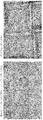
- FIG. 10 shows a micrograph of a culture container containing T cells. Then, the pump attached to the port was driven to feed the medium at three flow rates of 0.2 mL/min, 1 mL/min, and 3 mL/min, and a microscope was used to check whether single cell migration occurred. It was confirmed by the visual observation used. As a result, in the culture container of Example 2, single cell migration did not occur at all three flow rates.
- the present invention is not limited to the above embodiments and examples, and various modifications can be made within the scope of the present invention.
- the cell type and the size of the culture vessel are not limited to those shown in the examples, and may be of a size capable of forming, for example, 500,000 to 1 million spheres, or tens of millions of single cells. It can be appropriately changed, for example, by making it culturable.
- the present invention can be suitably used when efficiently creating a large number of uniformly-sized spheres arranged at equal intervals.
Landscapes
- Life Sciences & Earth Sciences (AREA)
- Chemical & Material Sciences (AREA)
- Engineering & Computer Science (AREA)
- Bioinformatics & Cheminformatics (AREA)
- Health & Medical Sciences (AREA)
- Wood Science & Technology (AREA)
- Biotechnology (AREA)
- Organic Chemistry (AREA)
- Zoology (AREA)
- Microbiology (AREA)
- Sustainable Development (AREA)
- Biomedical Technology (AREA)
- Biochemistry (AREA)
- General Engineering & Computer Science (AREA)
- General Health & Medical Sciences (AREA)
- Genetics & Genomics (AREA)
- Medicinal Chemistry (AREA)
- Apparatus Associated With Microorganisms And Enzymes (AREA)
- Micro-Organisms Or Cultivation Processes Thereof (AREA)
Abstract
スフェアなどの培養対象物を収容するための複数の凹部が形成された培養部を有する培養容器において、培地を1mL/分以上の流速で送液しても、凹部間におけるスフェアなどの移動を防止することを可能とする。スフェアを収容するための複数の凹部が形成された培養部を有する培養容器であって、少なくとも一つのポートが備えられ、凹部の深さが50~500μmであり、凹部の側壁の少なくとも一部が略垂直であり、側壁の略垂直部分の垂直方向の長さが、スフェアの最大径の半分より長い培養容器とする。
Description
本発明は、細胞培養技術に関し、特にスフェアの作成などを効率化する技術に関する。
近年、iPS細胞やES細胞などの幹細胞等の接着細胞を大量に培養する場合には、細胞を培養容器に接着させて増殖させるだけではなく、細胞に対して接着性の低い材料を塗工したマイクロウェルプレートなどを備えた培養容器を使用して、スフェア(スフェロイド,凝集塊)やオルガノイドを形成させることによって、細胞をより生体内に近い三次元的な状態で培養する方法が用いられている。
このような培養容器を使用したスフェアの培養においては、スフェアがウェル(凹部)から飛び出して他のウェルに移動してしまい、所望の大きさや形状のスフェアを得ることが難しいという問題があった。
すなわち、培地交換を行うために、多数のウェルを培養部に備えた培養バッグ(袋状の培養容器)内に培地を送液すると、スフェアは簡単にウェルから飛び出して他のウェルに移動する(以下、これをスフェアの移動と称する)ため、培地の流速を極めて遅くする必要があり、迅速な培地交換が非常に困難であった。このため、このような培養容器は、頻繁に培地交換が必要な長期間培養には不向きであった。
すなわち、培地交換を行うために、多数のウェルを培養部に備えた培養バッグ(袋状の培養容器)内に培地を送液すると、スフェアは簡単にウェルから飛び出して他のウェルに移動する(以下、これをスフェアの移動と称する)ため、培地の流速を極めて遅くする必要があり、迅速な培地交換が非常に困難であった。このため、このような培養容器は、頻繁に培地交換が必要な長期間培養には不向きであった。
スフェアの移動は、浅いウェルを備えた培養バッグを用いる場合に頻繁に生じるが、培地交換を適切に行うためには、浅いウェルを備えた培養バッグを用いることが好ましい。
すなわち、ウェルの深さが500μmより小さい、浅いウェルを備えた培養バッグを用いる場合、一般的に、培地を送液する速度(流速)を0.1mL/分以下にしなければスフェアの移動が生じ得るため、培養バッグから培地を全て排出するのに長時間を要するという問題があった。例えば、培養バッグ内の培地量が10mLの場合、0.1mL/分の流速で排出すると100分を要することになり、細胞にダメージを与えることが懸念された。
すなわち、ウェルの深さが500μmより小さい、浅いウェルを備えた培養バッグを用いる場合、一般的に、培地を送液する速度(流速)を0.1mL/分以下にしなければスフェアの移動が生じ得るため、培養バッグから培地を全て排出するのに長時間を要するという問題があった。例えば、培養バッグ内の培地量が10mLの場合、0.1mL/分の流速で排出すると100分を要することになり、細胞にダメージを与えることが懸念された。
スフェアの移動を防止するために、深いウェルを備えた培養バッグを用いることも考えられる。しかしながら、このような培養バッグでは、培地の交換が十分に行えないという問題があった。
例えば、開口部の幅が2mm、深さが700μmの1000個のウェルを備えた培養バッグを用いて、乳酸を溶かした培地2mLを充填した後、乳酸を含まない培地10mLを1mL/分の流速で培養バッグ内に送液した。その後、ウェル内の培地の乳酸濃度を測定することによって、ウェルに残留した培地量を計算した。その結果、ウェル内には、元の培地が約20%残留していることが分かった。この場合、200μmのスフェアであれば、残留している元の培地にその全体が埋まり、培養に支障が出ることが予想された。
例えば、開口部の幅が2mm、深さが700μmの1000個のウェルを備えた培養バッグを用いて、乳酸を溶かした培地2mLを充填した後、乳酸を含まない培地10mLを1mL/分の流速で培養バッグ内に送液した。その後、ウェル内の培地の乳酸濃度を測定することによって、ウェルに残留した培地量を計算した。その結果、ウェル内には、元の培地が約20%残留していることが分かった。この場合、200μmのスフェアであれば、残留している元の培地にその全体が埋まり、培養に支障が出ることが予想された。
これに対して、ウェルからスフェアが飛び出さないように所定の処置を施した状態で培養バッグを反転させて、ウェルから培地を排出することも考えられる。しかし、この方法でも、約7%の培地が表面張力によってウェル内に残留していた。また、培養バッグを反転させると、スフェアが培養バッグ内の上面に貼り付くなど、ダメージを受けることがあるため、培養バッグに培地を送液することによって、培地を交換することが望ましい。
一方、培地の全交換を行わず、例えば半量のみを交換することによって培養を行うことも考えられなくはない。しかし、実際に行ってみると、この方法ではiPS細胞のスフェアを適切に作成することはできなかった。
一方、培地の全交換を行わず、例えば半量のみを交換することによって培養を行うことも考えられなくはない。しかし、実際に行ってみると、この方法ではiPS細胞のスフェアを適切に作成することはできなかった。
現在、リジッドなマイクロウェルプレートなどの培養容器を用いることにより、研究用のスフェアの作成が行われている。しかしながら、このような従来の方法では、広い培養面積を得ることは難しく、スフェアの大量作成に適するものではなかった。
スフェアを大量に作成するためには、例えばA4程度のサイズ(約600cm2)で浅いウェルを備えた培養バッグを使用することが好ましい。このような培養バッグを用いて培地の液厚を2mm~10mmとして培養を行う場合には、培養バッグ内には120ml~600mlの培地が充填される。この場合には、培地の流速を1mL/分~10mL/分としてもスフェアの移動を生じることなく培地を排出することは可能である。しかしながら、培地の液厚を1mm以下として培養を行う場合には、培地の流速を0.1mL/分以下にしなければ、スフェアの移動が生じるため、例えば培地量が60mLである場合には、培地の排出に10時間かかることになり、実用化することが困難であった。
スフェアを大量に作成するためには、例えばA4程度のサイズ(約600cm2)で浅いウェルを備えた培養バッグを使用することが好ましい。このような培養バッグを用いて培地の液厚を2mm~10mmとして培養を行う場合には、培養バッグ内には120ml~600mlの培地が充填される。この場合には、培地の流速を1mL/分~10mL/分としてもスフェアの移動を生じることなく培地を排出することは可能である。しかしながら、培地の液厚を1mm以下として培養を行う場合には、培地の流速を0.1mL/分以下にしなければ、スフェアの移動が生じるため、例えば培地量が60mLである場合には、培地の排出に10時間かかることになり、実用化することが困難であった。
そこで、本発明者らは鋭意研究して、深さが50~500μm程度の浅いウェルを備えた培養容器であっても、ウェルの側壁の少なくとも一部を略垂直とし、略垂直部分の垂直方向の長さをスフェアの最大径の半分より長くすることによって、培地交換において培地を1mL/分以上の流速で送液してもスフェアの移動を防止できることを見いだして、本発明を完成させた。
ここで、側壁の少なくとも一部が略垂直であるウェルを備えた培養容器について記載のある先行文献として、特許文献1を挙げることができる。
特許文献1には、底面が角度120度以下のロート状、曲率半径が10mm以下の半球状、またはそれらの底面の中心部を平面にした形状をなす培養容器が開示されている。しかし、これらの培養容器は、リジッドな培養容器でスフェアを形成することを想定したものであり、培養バッグに培地を送液する場合における上記の問題を解消可能なものではなかった。
特許文献1には、底面が角度120度以下のロート状、曲率半径が10mm以下の半球状、またはそれらの底面の中心部を平面にした形状をなす培養容器が開示されている。しかし、これらの培養容器は、リジッドな培養容器でスフェアを形成することを想定したものであり、培養バッグに培地を送液する場合における上記の問題を解消可能なものではなかった。
すなわち、例えば軟包材からなる培養バッグを用いる場合には、その上面部と下面部の間の厚みに従って、培地の流速を大きく変更する必要があるため、スフェアの移動の防止及び培地の流速の制御は、重要な問題となっていた。
例えば、上述したように、培地の液厚が2mm以上であれば、培地の流速を1mL/分としてもスフェアの移動を生じることなく培地を排出することが可能であるが、培地の液厚が1mm以下であれば、培地の流速を0.1mL/分程度に遅くしなければ、スフェアの移動が生じてしまう。また、培地の液厚が0.5mm以下の場合には、培地の流速を0.05mL/分以下にしなければならなかった。
例えば、上述したように、培地の液厚が2mm以上であれば、培地の流速を1mL/分としてもスフェアの移動を生じることなく培地を排出することが可能であるが、培地の液厚が1mm以下であれば、培地の流速を0.1mL/分程度に遅くしなければ、スフェアの移動が生じてしまう。また、培地の液厚が0.5mm以下の場合には、培地の流速を0.05mL/分以下にしなければならなかった。
本発明は、上記事情に鑑みてなされたものであり、スフェアなどの培養対象物を収容するための複数の凹部が形成された培養部を有する培養容器において、培地を1mL/分以上の流速で送液しても、凹部間におけるスフェアなどの移動を防止することが可能な培養容器、培養方法、及び培養装置の提供を目的とする。
上記目的を達成するため、本発明の培養容器は、スフェアを収容するための複数の凹部が形成された培養部を有する培養容器であって、少なくとも一つのポートが備えられ、前記凹部の深さが50~500μmであり、前記凹部の側壁の少なくとも一部が略垂直であり、前記側壁の略垂直部分の垂直方向の長さが、スフェアの最大径の半分より長い構成としてある。
また、本発明の培養方法は、上記の培養容器を用いて、一方のポートから培地を注入し、他方のポートから培地を排出して、培地の流速を制御する方法としてある。
また、本発明の培養装置は、上記の培養容器の上面に接して押圧板が備えられ、前記培養容器が前記押圧板により押圧され、前記押圧板が、前記培養容器への培地の注入又は排出に伴って垂直方向に移動可能である構成としてある。
本発明によれば、スフェアなどの培養対象物を収容するための複数の凹部が形成された培養部を有する培養容器において、培地を1mL/分以上の流速で送液しても、凹部間におけるスフェアなどの移動を防止することが可能な培養容器、培養方法、及び培養装置の提供が可能となる。
以下、本発明の培養容器、培養方法、及び培養装置の実施形態について、図面を参照して詳細に説明する。ただし、本発明は、以下の実施形態及び実施例の具体的な内容に限定されるものではない。
図1に示すように、本実施形態の培養容器10は、スフェアなどの培養対象物を収容するための複数の凹部(ウェル)が形成された培養部11を有する培養容器であって、少なくとも一つのポート13が備えられている。このポート13にはチューブ14が接続され、図示しないがチューブ14に配設されたポンプなどにより、培養容器10への培地1の注入、及び培養容器10からの培地1の排出が行われるようになっている。
また、図1において、培養容器10は、軟包材からなり、バッグ状に形成されており、天板部12を有している。培養容器10に注入される培地1の量に応じて、培養部11と天板部12との間隔(液厚L)が変化するようになっている。
さらに、本実施形態の培養容器10の変形例を図2に示す。この変形例では、培養容器10a内における培地1の液厚をより均一化することができると共に、全ての凹部を設置面と並行に接触させることができる。これにより、培養対象物の増殖性の差異や細胞播種時の細胞数のバラツキを低減することが可能になっている。その他の構成は、図1に示す培養容器10と同様である。
さらに、本実施形態の培養容器10の変形例を図2に示す。この変形例では、培養容器10a内における培地1の液厚をより均一化することができると共に、全ての凹部を設置面と並行に接触させることができる。これにより、培養対象物の増殖性の差異や細胞播種時の細胞数のバラツキを低減することが可能になっている。その他の構成は、図1に示す培養容器10と同様である。
培養部11における複数の凹部は、図3に示すように、側壁の少なくとも一部が略垂直状に形成されている。また、これらの凹部には、培養対象物2が収容され、側壁の略垂直部分の垂直方向の長さ(b)が、培養対象物2の最大径の半分(c)より長くなっている。
凹部における側壁が略垂直である領域の形状は、例えば、円柱状、四角柱状等とすることができる。また、培養部11における複数の凹部の配置は、例えば、千鳥状や格子状等とすることができる。
培養容器10における凹部をこのような構成とすることによって、ポート13から培養容器10に培地1を送液した場合に、その流速を1mL/分以上にしても、凹部から培養対象物2が飛び出して、他の凹部へ移動することを防止することが可能になっている。
凹部における側壁が略垂直である領域の形状は、例えば、円柱状、四角柱状等とすることができる。また、培養部11における複数の凹部の配置は、例えば、千鳥状や格子状等とすることができる。
培養容器10における凹部をこのような構成とすることによって、ポート13から培養容器10に培地1を送液した場合に、その流速を1mL/分以上にしても、凹部から培養対象物2が飛び出して、他の凹部へ移動することを防止することが可能になっている。
培養対象物2がスフェアである場合、凹部の深さ(a)としては、50~500μmとすることが好ましい。凹部の深さ(a)を500μmより大きくすると、培養容器10に培地1を送液しても、凹部内の培地を十分に置換することが困難になる場合があるためである。また、500μmより深い凹部を備えた培養容器は、加工難易度が高くなるためである。
ここで、1個のスフェアは、約200個から数千個程度のシングルセル(単一細胞)を凝集させることによって形成させることができる。このようにして形成されたスフェアの大きさは、小さいもので、50μm~100μm程度であり、大きいものでは、200μm~300μm程度である。
したがって、凹部の深さ(a)としては、75~500μmとすることも好ましく、100~500μmとすることも好ましい。また、凹部の深さ(a)を、100~400μmとすることも好ましく、100~250μmとすることも好ましい。
したがって、凹部の深さ(a)としては、75~500μmとすることも好ましく、100~500μmとすることも好ましい。また、凹部の深さ(a)を、100~400μmとすることも好ましく、100~250μmとすることも好ましい。
凹部内の底部の形状は、特に限定されないが、培養対象物2がスフェアの場合には、シングルセルを凝集し易くしてスフェアの形成を好適に行えるようにするため、錐体状、半球状、又はアール状とすることが好ましい。
培養対象物2がシングルセルである場合、凹部の深さ(a)としては、5~50μmとすることが好ましい。シングルセルの大きさは、6μm~15μm程度であり、10μm程度のものが多いためである。したがって、この場合、凹部の深さ(a)としては、6~50μmとすることも好ましく、10~50μmとすることも好ましい。また、凹部の深さ(a)を、10~40μmとすることも好ましく、10~25μmとすることも好ましい。
凹部の開口部の形状は、特に限定されず、円形、又は正方形などの矩形状とすることができる。また、凹部の開口部の幅は、培養対象物2のサイズに合わせて、適宜設定することができる。
例えば、培養対象物2をスフェアとする場合、凹部の開口部の円又は内接円の直径の下限を、60μm以上,70μm以上,80μm以上,90μm以上,100μm以上,110μm以上,120μm以上,150μm以上等としてもよい。また、凹部の開口部の円又は内接円の直径の上限を、1mm以下,900μm以下,800μm以下,700μm以下,500μm以下等としてもよい。
また、培養対象物2をシングルセルとする場合、凹部の開口部の円又は内接円の直径の下限を、5μm以上,6μm以上,8μm以上等としてもよい。また、凹部の開口部の円又は内接円の直径の上限を、50μm以下,40μm以下,30μm以下等としてもよい。
例えば、培養対象物2をスフェアとする場合、凹部の開口部の円又は内接円の直径の下限を、60μm以上,70μm以上,80μm以上,90μm以上,100μm以上,110μm以上,120μm以上,150μm以上等としてもよい。また、凹部の開口部の円又は内接円の直径の上限を、1mm以下,900μm以下,800μm以下,700μm以下,500μm以下等としてもよい。
また、培養対象物2をシングルセルとする場合、凹部の開口部の円又は内接円の直径の下限を、5μm以上,6μm以上,8μm以上等としてもよい。また、凹部の開口部の円又は内接円の直径の上限を、50μm以下,40μm以下,30μm以下等としてもよい。
また、本実施形態の培養容器10において、2つのポート13を備えることが好ましく、これらのポート13を凹部の側壁の略垂直部分に対して垂直方向に(底面に平行に)、培養容器の両端において対向して備えることが好ましい。
また、このような培養容器10を用いて、一方のポート13から培地1を注入し、他方のポート13から培地1を排出して、培地の流速を制御することが好ましい。
このとき、培地1の流速としては、1mL/分以上に制御することが好ましく、3mL/分以上に制御することがより好ましく、5mL/分以上に制御することがさらに好ましく、10mL/分以上に制御することがさらにまた好ましい。
また、このような培養容器10を用いて、一方のポート13から培地1を注入し、他方のポート13から培地1を排出して、培地の流速を制御することが好ましい。
このとき、培地1の流速としては、1mL/分以上に制御することが好ましく、3mL/分以上に制御することがより好ましく、5mL/分以上に制御することがさらに好ましく、10mL/分以上に制御することがさらにまた好ましい。
このような本実施形態の培養容器の写真を図4に示す。また、培養容器の培養部の一部の顕微鏡写真を図7に示す。この培養容器は、培養部に約50000個の凹部を備えており、凹部の深さが250μmであり、凹部の側壁の略垂直部分の垂直方向の長さが170μmであり、凹部の開口部の形状が正方形であり、その内接円の直径が260μmであり、凹部の底部が錐状であり、凹部の開口部の間隔が40μmである。
また、2つのポートが、凹部の側壁の略垂直部分に対して垂直方向に、培養容器の両端において対向して備えられている。
後述するように、この培養容器の凹部に直径200μmのスフェア等を入れて、培養容器の一方のポートから培地を注入し、他方のポートから培地を排出して、培地の流速を3mL/分等に制御した。その結果、樹脂ビーズが凹部から飛び出して他の凹部へ移動することは、観察されなかった。
後述するように、この培養容器の凹部に直径200μmのスフェア等を入れて、培養容器の一方のポートから培地を注入し、他方のポートから培地を排出して、培地の流速を3mL/分等に制御した。その結果、樹脂ビーズが凹部から飛び出して他の凹部へ移動することは、観察されなかった。
ここで、本実施形態における培地の流速は、注入及び排出する培地量から計算され得るが、培養容器10内における培地の実際の流速は、培養容器10内の場所、及び液厚の変化によって異なる。すなわち、培養容器10内ではポート13付近の流速が最も早いため、この領域の凹部から培養対象物2が移動しないことが重要である。
また、天板部12を押圧することによって液厚を小さくすればするほど、流速は早くなる。このため、このような場合でも、凹部から培養対象物2が移動しないことが重要である。
また、天板部12を押圧することによって液厚を小さくすればするほど、流速は早くなる。このため、このような場合でも、凹部から培養対象物2が移動しないことが重要である。
本実施形態の培養容器10の材料としては、ポリエチレンやポリプロピレンなどのポリオレフィン系樹脂などを好適に用いることができる。例えば、ポリエチレン、エチレンとα-オレフィンの共重合体、エチレンと酢酸ビニルの共重合体、エチレンとアクリル酸やメタクリル酸共重合体と金属イオンを用いたアイオノマー等を挙げることができる。また、ポリオレフィン、スチレン系エラストマー、ポリエステル系熱可塑性エラストマー、シリコーン系熱可塑性エラストマー、シリコーン樹脂等を用いることもできる。さらに、シリコーンゴム、軟質塩化ビニル樹脂、ポリブタジエン樹脂、エチレン-酢酸ビニル共重合体、塩素化ポリエチレン樹脂、ポリウレタン系熱可塑性エラストマー、ポリエステル系熱可塑性エラストマー、シリコーン系熱可塑性エラストマー、スチレン系エラストマー、例えば、SBS(スチレン・ブタジエン・スチレン)、SIS(スチレン・イソプレン・スチレン)、SEBS(スチレン・エチレン・ブチレン・スチレン)、SEPS(スチレン・エチレン・プロピレン・スチレン)、ポリオレフィン樹脂、フッ素系樹脂等を用いてもよい。
また、培養対象物2をスフェアとする場合、本実施形態の培養容器10内において、培養部11には、スフェアやシングルセルが接着しないように、低接着性表面処理塗工を行うことが好ましい。具体的には、細胞接着抑制剤(細胞低接着処理剤)を塗布しておくことが好ましい。
細胞接着抑制剤としては、リン脂質ポリマー、ポリビニルアルコール誘導体、リン脂質・高分子複合体、ポリヒドロキシエチルメタクリレート、ポリビニルアルコール、アガロース、キトサン、ポリエチレングリコール、アルブミン等を用いることができる。また、これらを組み合わせて用いてもよい。
細胞接着抑制剤としては、リン脂質ポリマー、ポリビニルアルコール誘導体、リン脂質・高分子複合体、ポリヒドロキシエチルメタクリレート、ポリビニルアルコール、アガロース、キトサン、ポリエチレングリコール、アルブミン等を用いることができる。また、これらを組み合わせて用いてもよい。
培養対象物2をスフェアとする場合、本実施形態の培養容器10は、スフェアを形成する工程、スフェア状態を維持したまま培養して増殖させる工程、及びスフェア状態で分化誘導する工程等に用いることができる。
また、iPS細胞やES細胞、その他幹細胞から既に分化誘導工程を経て得られた分化細胞を使用してスフェアを形成させる方法や、分化誘導した細胞を一度凍結保存し、再度解凍後にスフェアを形成する方法等において用いることもできる。
また、iPS細胞やES細胞、その他幹細胞から既に分化誘導工程を経て得られた分化細胞を使用してスフェアを形成させる方法や、分化誘導した細胞を一度凍結保存し、再度解凍後にスフェアを形成する方法等において用いることもできる。
なお、天板部12において、培養容器10の内側に天板突起部を備えて、天板突起部の幅を凹部の開口部の幅よりも小さくし、かつ、天板突起部の高さを培養対象物2の最小径より小さくして、天板突起部が培養部11の上端面111の一部に接触した場合に、上端面111と天板部12に間隙が形成される構成とすることも好ましい。
本実施形態の培養容器10をこのような構成にすれば、培養部11の凹部に形状により、培地を1mL/分以上の流速で送液しても凹部間におけるスフェアの移動を防止可能であることに加え、例えばより迅速に培地交換を行う必要が生じた場合に、天板突起部を上端面111の一部に接触させて、培養対象物2のサイズよりも小さい間隙を上端面111と天板部12に形成させた状態にすることができる。これにより、培地などの液状物を間隙から通液可能としつつ、スフェアなどの培養対象物の移動を防止することが可能となる。
また、本実施形態の培養装置は、図5に示すように、培養容器10、積載台20、ガイドピン21、及び押圧板30を備えている。また、この培養装置に、図2に示す培養容器10aを配置した例を図6に示す。
培養容器10は積載台20に配置され、その上面に接して押圧板30が配置されている。積載台20の四隅にはガイドピン21が立設され、押圧板30はこれらのガイドピン21により垂直方向に移動可能に支持されている。
培養容器10は積載台20に配置され、その上面に接して押圧板30が配置されている。積載台20の四隅にはガイドピン21が立設され、押圧板30はこれらのガイドピン21により垂直方向に移動可能に支持されている。
すなわち、押圧板30の自重によって、培養容器10を一定の圧力で押圧するように固定することができる。また、ガイドピン21にバネ材を設置して、押圧板20を培養容器10に適宜押し付けることができる。これにより、培養容器10への培地の注入又は排出に伴って、押圧板30を垂直方向に移動可能とすることができる。
本実施形態の培養装置によれば、このような構成によって、培養容器10における培地の流速をより適切に制御することが可能になっている。
本実施形態の培養装置によれば、このような構成によって、培養容器10における培地の流速をより適切に制御することが可能になっている。
以上説明したように、本実施形態の培養容器、培養方法、及び培養装置によれば、スフェアなどの培養対象物を収容するための複数の凹部が形成された培養部を有する培養容器において、培地を1mL/分以上の流速で送液しても、凹部間におけるスフェアなどの移動を防止することが可能になっている。
以下、本発明の実施形態に係る培養容器の効果を確認するために行った試験について説明する。
(実施例1)
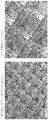
実施例1の培養容器として、凹部の深さが250μmであり、凹部の側壁の略垂直部分の垂直方向の長さが170μmであり、凹部の開口部の形状が正方形であり、その内接円の直径が260μmであり、凹部の底部が錐状であり、凹部の開口部の間隔が40μmであり、凹部を50000個備えた培養部を有するものを作成した。作成した培養容器の顕微鏡写真を図7に示す。同図の左の写真は培養容器の一部を示しており、右の写真はその一部を拡大したものである。
また、培養対象物として、擬似のスフェアと、実物のスフェアを準備した。擬似のスフェアは、直径が200μmに揃った樹脂ビーズであり、実物のスフェアは、iPSのスフェアで直径が約80μmのものである。
実施例1の培養容器として、凹部の深さが250μmであり、凹部の側壁の略垂直部分の垂直方向の長さが170μmであり、凹部の開口部の形状が正方形であり、その内接円の直径が260μmであり、凹部の底部が錐状であり、凹部の開口部の間隔が40μmであり、凹部を50000個備えた培養部を有するものを作成した。作成した培養容器の顕微鏡写真を図7に示す。同図の左の写真は培養容器の一部を示しており、右の写真はその一部を拡大したものである。
また、培養対象物として、擬似のスフェアと、実物のスフェアを準備した。擬似のスフェアは、直径が200μmに揃った樹脂ビーズであり、実物のスフェアは、iPSのスフェアで直径が約80μmのものである。
培地としてStemFit AK02N(品番RCAK02N,味の素株式会社)を使用して、培養容器内に充填した後、擬似のスフェアと実物のスフェアをそれぞれ別個に培養容器内に注入して全体に分散させ、凹部内に収容した。図8に、樹脂ビーズを入れて培地を送液している状態の顕微鏡写真を示す。また、図9に、iPS細胞のスフェアを収容した状態の培養容器の顕微鏡写真を示す。
そして、ポートに取り付けたポンプを駆動させて、培地を0.2mL/分、1mL/分、3mL/分の3種類の流速で送液し、スフェアの移動が生じたか否かについて、顕微鏡を用いた目視観察によって確認した。
その結果、実施例1の培養容器では、擬似のスフェアと実物のスフェアの両方について、3種類の全ての流速において、スフェアの移動は生じなかった。
その結果、実施例1の培養容器では、擬似のスフェアと実物のスフェアの両方について、3種類の全ての流速において、スフェアの移動は生じなかった。
(参考例1)
参考例1の培養容器として、凹部の深さが500μmであり、凹部の側壁がアール状であり、凹部の開口部の形状が円形であり、その直径が1mmであり、凹部の開口部の間隔が50μmであり、凹部を4000個備えた培養部を有するものを準備した。
また、培養対象物として、実施例1と同様に、擬似のスフェアと、実物のスフェアを準備した。
参考例1の培養容器として、凹部の深さが500μmであり、凹部の側壁がアール状であり、凹部の開口部の形状が円形であり、その直径が1mmであり、凹部の開口部の間隔が50μmであり、凹部を4000個備えた培養部を有するものを準備した。
また、培養対象物として、実施例1と同様に、擬似のスフェアと、実物のスフェアを準備した。
実施例1と同様の培地を培養容器内に充填した後、擬似のスフェアと実物のスフェアをそれぞれ別個に培養容器内に注入して全体に分散させ、凹部内に収容した。
そして、ポートに取り付けたポンプを駆動させて、培地を0.2mL/分、1mL/分、3mL/分の3種類の流速で送液し、スフェアの移動が生じたか否かについて、顕微鏡を用いた目視観察によって確認した。
その結果、参考例1の培養容器では、擬似のスフェアと実物のスフェアの両方について、3種類の全ての流速において、スフェアの移動は生じなかった。
そして、ポートに取り付けたポンプを駆動させて、培地を0.2mL/分、1mL/分、3mL/分の3種類の流速で送液し、スフェアの移動が生じたか否かについて、顕微鏡を用いた目視観察によって確認した。
その結果、参考例1の培養容器では、擬似のスフェアと実物のスフェアの両方について、3種類の全ての流速において、スフェアの移動は生じなかった。
(比較例1)
比較例1の培養容器として、凹部の深さが250μmであり、凹部の側壁がアール状であり、凹部の開口部の形状が円形であり、その直径が1mmであり、凹部の開口部の間隔が50μmであり、凹部を4000個備えた培養部を有するものを準備した。
また、培養対象物として、実施例1と同様に、擬似のスフェアと、実物のスフェアを準備した。
比較例1の培養容器として、凹部の深さが250μmであり、凹部の側壁がアール状であり、凹部の開口部の形状が円形であり、その直径が1mmであり、凹部の開口部の間隔が50μmであり、凹部を4000個備えた培養部を有するものを準備した。
また、培養対象物として、実施例1と同様に、擬似のスフェアと、実物のスフェアを準備した。
実施例1と同様の培地を培養容器内に充填した後、擬似のスフェアと実物のスフェアをそれぞれ別個に培養容器内に注入して全体に分散させ、凹部内に収容した。
そして、ポートに取り付けたポンプを駆動させて、培地を0.2mL/分、1mL/分、3mL/分の3種類の流速で送液し、スフェアの移動が生じたか否かについて、顕微鏡を用いた目視観察によって確認した。
その結果、比較例1の培養容器では、擬似のスフェアと実物のスフェアの両方について、3種類の全ての流速において、スフェアの移動が生じた。
そして、ポートに取り付けたポンプを駆動させて、培地を0.2mL/分、1mL/分、3mL/分の3種類の流速で送液し、スフェアの移動が生じたか否かについて、顕微鏡を用いた目視観察によって確認した。
その結果、比較例1の培養容器では、擬似のスフェアと実物のスフェアの両方について、3種類の全ての流速において、スフェアの移動が生じた。
(実施例2)
実施例2の培養容器として、凹部の深さが30μmであり、凹部の側壁の略垂直部分の垂直方向の長さが20μmであり、凹部の開口部の形状が正方形であり、その内接円の直径が20μmであり、凹部の底部が錐状であり、凹部の開口部の間隔が10μmであり、凹部を100000個備えた培養部を有するものを作成した。
また、培養対象物として、シングルセル(ヒトT細胞)を準備した。
実施例2の培養容器として、凹部の深さが30μmであり、凹部の側壁の略垂直部分の垂直方向の長さが20μmであり、凹部の開口部の形状が正方形であり、その内接円の直径が20μmであり、凹部の底部が錐状であり、凹部の開口部の間隔が10μmであり、凹部を100000個備えた培養部を有するものを作成した。
また、培養対象物として、シングルセル(ヒトT細胞)を準備した。
実施例1と同様の培地を培養容器内に充填した後、T細胞を培養容器内に注入して全体に分散させ、凹部内に収容した。図10に、T細胞を収容した培養容器の顕微鏡写真を示す。
そして、ポートに取り付けたポンプを駆動させて、培地を0.2mL/分、1mL/分、3mL/分の3種類の流速で送液し、シングルセルの移動が生じたか否かについて、顕微鏡を用いた目視観察によって確認した。
その結果、実施例2の培養容器では、3種類の全ての流速において、シングルセルの移動は生じなかった。
そして、ポートに取り付けたポンプを駆動させて、培地を0.2mL/分、1mL/分、3mL/分の3種類の流速で送液し、シングルセルの移動が生じたか否かについて、顕微鏡を用いた目視観察によって確認した。
その結果、実施例2の培養容器では、3種類の全ての流速において、シングルセルの移動は生じなかった。
本発明は、以上の実施形態及び実施例に限定されるものではなく、本発明の範囲内において、種々の変更実施が可能であることは言うまでもない。例えば、細胞種や培養容器の大きさは実施例に示したものに限定されず、例えば50万個~100万個のスフェアを形成可能な大きさのものにしたり、数1000万個のシングルセルが培養可能な大きさにするなど適宜変更することが可能である。
本発明は、等間隔に配列された均一なサイズのスフェアを効率的に大量に作成する場合などに、好適に利用することが可能である。
この明細書に記載の文献及び本願のパリ優先の基礎となる日本出願明細書の内容を全てここに援用する。
10 培養容器
11 培養部
12 天板部
13 ポート
14 チューブ
20 積載台
21 ガイドピン
30 押圧板
11 培養部
12 天板部
13 ポート
14 チューブ
20 積載台
21 ガイドピン
30 押圧板
Claims (11)
- スフェアを収容するための複数の凹部が形成された培養部を有する培養容器であって、少なくとも一つのポートが備えられ、前記凹部の深さが50~500μmであり、前記凹部の側壁の少なくとも一部が略垂直であり、前記側壁の略垂直部分の垂直方向の長さが、25μmより長いことを特徴とする培養容器。
- 前記側壁の略垂直部分の垂直方向の長さが、スフェアの最大径の半分より長いことを特徴とする請求項1記載の培養容器。
- 単一細胞を収容するための複数の凹部が形成された培養部を有する培養容器であって、少なくとも一つのポートが備えられ、前記凹部の深さが5~50μmであり、前記凹部の側壁の少なくとも一部が略垂直であり、前記側壁の略垂直部分の垂直方向の長さが、3μmより長いことを特徴とする培養容器。
- 前記側壁の略垂直部分の垂直方向の長さが、単一細胞の最大径の半分より長いことを特徴とする請求項3記載の培養容器。
- 軟包材からなることを特徴とする請求項1~4のいずれかに記載の培養容器。
- バッグ形状であることを特徴とする請求項1~5のいずれかに記載の培養容器。
- 前記側壁の略垂直部分に対して垂直方向に、培養容器の両端において対向して2つのポートが備えられたことを特徴とする請求項6記載の培養容器。
- 前記凹部の底部が、錐体状、半球状、又はアール状であることを特徴とする請求項1~7のいずれかに記載の培養容器。
- 請求項7記載の培養容器を用いて、一方のポートから培地を注入し、他方のポートから培地を排出して、培地の流速を制御することを特徴とする培養方法。
- 前記培地の流速を1mL/分以上に制御することを特徴とする請求項9記載の培養方法。
- 請求項1~8のいずれかに記載の培養容器の上面に接して押圧板が備えられ、前記培養容器が前記押圧板により押圧され、前記押圧板が、前記培養容器への培地の注入又は排出に伴って垂直方向に移動可能であることを特徴とする培養装置。
Applications Claiming Priority (2)
| Application Number | Priority Date | Filing Date | Title |
|---|---|---|---|
| JP2019006652A JP7348586B2 (ja) | 2019-01-18 | 2019-01-18 | 培養容器、培養方法、及び培養装置 |
| JP2019-006652 | 2019-01-18 |
Publications (1)
| Publication Number | Publication Date |
|---|---|
| WO2020149246A1 true WO2020149246A1 (ja) | 2020-07-23 |
Family
ID=71614413
Family Applications (1)
| Application Number | Title | Priority Date | Filing Date |
|---|---|---|---|
| PCT/JP2020/000776 Ceased WO2020149246A1 (ja) | 2019-01-18 | 2020-01-12 | 培養容器、培養方法、及び培養装置 |
Country Status (2)
| Country | Link |
|---|---|
| JP (1) | JP7348586B2 (ja) |
| WO (1) | WO2020149246A1 (ja) |
Citations (10)
| Publication number | Priority date | Publication date | Assignee | Title |
|---|---|---|---|---|
| JP2008306987A (ja) * | 2007-06-15 | 2008-12-25 | Covalent Materials Corp | 細胞培養担体および細胞の培養方法 |
| WO2009034927A1 (ja) * | 2007-09-12 | 2009-03-19 | Kitakyushu Foundation For The Advancement Of Industry, Science And Technology | 細胞培養器具及びこれを用いた細胞培養方法 |
| US20120264210A1 (en) * | 2009-11-03 | 2012-10-18 | Maco Pharma | Method for Expanding and/or Preserving Cells by Means of Gas Enrichment of the Culture Medium |
| US20120295289A1 (en) * | 2009-11-13 | 2012-11-22 | The Governing Council Of The University Of Toronto | Device and method for culturing cells |
| WO2014061244A1 (ja) * | 2012-10-18 | 2014-04-24 | 株式会社クラレ | 毒性スクリーニング方法 |
| WO2016121292A1 (ja) * | 2015-01-30 | 2016-08-04 | 東洋製罐グループホールディングス株式会社 | 細胞培養方法、及び細胞培養装置 |
| WO2017183570A1 (ja) * | 2016-04-18 | 2017-10-26 | 東洋製罐グループホールディングス株式会社 | 細胞培養用容器、及びその使用方法 |
| JP2017532970A (ja) * | 2014-10-29 | 2017-11-09 | コーニング インコーポレイテッド | 灌流バイオリアクタ・プラットフォーム |
| JP3214876U (ja) * | 2017-11-30 | 2018-02-08 | Agcテクノグラス株式会社 | 培養基材 |
| JP2018504103A (ja) * | 2014-12-22 | 2018-02-15 | エコール ポリテクニーク フェデラル ドゥ ローザンヌ (イーピーエフエル) | 高い収集能力で哺乳動物細胞を操作(マニピュレーション)する装置 |
-
2019
- 2019-01-18 JP JP2019006652A patent/JP7348586B2/ja active Active
-
2020
- 2020-01-12 WO PCT/JP2020/000776 patent/WO2020149246A1/ja not_active Ceased
Patent Citations (10)
| Publication number | Priority date | Publication date | Assignee | Title |
|---|---|---|---|---|
| JP2008306987A (ja) * | 2007-06-15 | 2008-12-25 | Covalent Materials Corp | 細胞培養担体および細胞の培養方法 |
| WO2009034927A1 (ja) * | 2007-09-12 | 2009-03-19 | Kitakyushu Foundation For The Advancement Of Industry, Science And Technology | 細胞培養器具及びこれを用いた細胞培養方法 |
| US20120264210A1 (en) * | 2009-11-03 | 2012-10-18 | Maco Pharma | Method for Expanding and/or Preserving Cells by Means of Gas Enrichment of the Culture Medium |
| US20120295289A1 (en) * | 2009-11-13 | 2012-11-22 | The Governing Council Of The University Of Toronto | Device and method for culturing cells |
| WO2014061244A1 (ja) * | 2012-10-18 | 2014-04-24 | 株式会社クラレ | 毒性スクリーニング方法 |
| JP2017532970A (ja) * | 2014-10-29 | 2017-11-09 | コーニング インコーポレイテッド | 灌流バイオリアクタ・プラットフォーム |
| JP2018504103A (ja) * | 2014-12-22 | 2018-02-15 | エコール ポリテクニーク フェデラル ドゥ ローザンヌ (イーピーエフエル) | 高い収集能力で哺乳動物細胞を操作(マニピュレーション)する装置 |
| WO2016121292A1 (ja) * | 2015-01-30 | 2016-08-04 | 東洋製罐グループホールディングス株式会社 | 細胞培養方法、及び細胞培養装置 |
| WO2017183570A1 (ja) * | 2016-04-18 | 2017-10-26 | 東洋製罐グループホールディングス株式会社 | 細胞培養用容器、及びその使用方法 |
| JP3214876U (ja) * | 2017-11-30 | 2018-02-08 | Agcテクノグラス株式会社 | 培養基材 |
Also Published As
| Publication number | Publication date |
|---|---|
| JP7348586B2 (ja) | 2023-09-21 |
| JP2020114191A (ja) | 2020-07-30 |
Similar Documents
| Publication | Publication Date | Title |
|---|---|---|
| CN103814125B (zh) | 粘附性细胞的培养方法 | |
| EP3652291B1 (en) | Cell culture vessel | |
| JP7102734B2 (ja) | 細胞培養方法及び装置 | |
| JP7092235B2 (ja) | 細胞培養容器、細胞培養容器の支持治具、及び細胞培養方法 | |
| US20200255782A1 (en) | Spheroid-producing device, method for recovering spheroids, and method for producing spheroids | |
| US20200181552A1 (en) | Handling features for microcavity cell culture vessel | |
| US12252676B2 (en) | Cell culture system | |
| CN113906131A (zh) | 用于细胞聚集体的细胞贮存和运输介质及运输系统和方法 | |
| TW201639952A (zh) | 細胞培養方法以及細胞培養裝置 | |
| US20140093962A1 (en) | Non-adherent cell support and manufacturing method | |
| JP6814380B2 (ja) | 細胞スフェロイドの製造方法 | |
| JP7379824B2 (ja) | 液厚制御機構、培養装置、及び液厚制御方法 | |
| WO2020149246A1 (ja) | 培養容器、培養方法、及び培養装置 | |
| US11857970B2 (en) | Cell culture vessel | |
| JP2023017088A (ja) | スフェア培養部材、培養容器、穴開き部材の加工方法、及び洗浄容器 | |
| US12351787B2 (en) | Culture container, culture method, and transportation method | |
| US20210380917A1 (en) | Method for producing culture vessel, and culture vessel | |
| US20230416664A1 (en) | Open-well microcavity plate | |
| TW201814037A (zh) | 細胞培養容器、細胞培養系統、細胞培養方法,及細胞培養容器的製造方法 | |
| WO2022270093A1 (ja) | 細胞培養方法、細胞培養キット、及び細胞培養システム | |
| WO2022014436A1 (ja) | 細胞培養容器、細胞培養容器の製造方法、細胞の製造方法、細胞培養装置、及び細胞培養用治具 | |
| JP2021141820A (ja) | 袋状培養容器 |
Legal Events
| Date | Code | Title | Description |
|---|---|---|---|
| 121 | Ep: the epo has been informed by wipo that ep was designated in this application |
Ref document number: 20741287 Country of ref document: EP Kind code of ref document: A1 |
|
| NENP | Non-entry into the national phase |
Ref country code: DE |
|
| 122 | Ep: pct application non-entry in european phase |
Ref document number: 20741287 Country of ref document: EP Kind code of ref document: A1 |