WO2020149029A1 - 加硫ゴム材料のオゾン劣化評価方法および評価システム - Google Patents
加硫ゴム材料のオゾン劣化評価方法および評価システム Download PDFInfo
- Publication number
- WO2020149029A1 WO2020149029A1 PCT/JP2019/046744 JP2019046744W WO2020149029A1 WO 2020149029 A1 WO2020149029 A1 WO 2020149029A1 JP 2019046744 W JP2019046744 W JP 2019046744W WO 2020149029 A1 WO2020149029 A1 WO 2020149029A1
- Authority
- WO
- WIPO (PCT)
- Prior art keywords
- ozone
- test sample
- vulcanized rubber
- rubber material
- test
- Prior art date
- Legal status (The legal status is an assumption and is not a legal conclusion. Google has not performed a legal analysis and makes no representation as to the accuracy of the status listed.)
- Ceased
Links
Images




Classifications
-
- G—PHYSICS
- G01—MEASURING; TESTING
- G01N—INVESTIGATING OR ANALYSING MATERIALS BY DETERMINING THEIR CHEMICAL OR PHYSICAL PROPERTIES
- G01N33/00—Investigating or analysing materials by specific methods not covered by groups G01N1/00 - G01N31/00
- G01N33/44—Resins; Plastics; Rubber; Leather
- G01N33/445—Rubber
-
- G—PHYSICS
- G01—MEASURING; TESTING
- G01B—MEASURING LENGTH, THICKNESS OR SIMILAR LINEAR DIMENSIONS; MEASURING ANGLES; MEASURING AREAS; MEASURING IRREGULARITIES OF SURFACES OR CONTOURS
- G01B11/00—Measuring arrangements characterised by the use of optical techniques
- G01B11/30—Measuring arrangements characterised by the use of optical techniques for measuring roughness or irregularity of surfaces
- G01B11/303—Measuring arrangements characterised by the use of optical techniques for measuring roughness or irregularity of surfaces using photoelectric detection means
-
- G—PHYSICS
- G01—MEASURING; TESTING
- G01N—INVESTIGATING OR ANALYSING MATERIALS BY DETERMINING THEIR CHEMICAL OR PHYSICAL PROPERTIES
- G01N17/00—Investigating resistance of materials to the weather, to corrosion, or to light
- G01N17/002—Test chambers
-
- G—PHYSICS
- G01—MEASURING; TESTING
- G01N—INVESTIGATING OR ANALYSING MATERIALS BY DETERMINING THEIR CHEMICAL OR PHYSICAL PROPERTIES
- G01N21/00—Investigating or analysing materials by the use of optical means, i.e. using sub-millimetre waves, infrared, visible or ultraviolet light
- G01N21/17—Systems in which incident light is modified in accordance with the properties of the material investigated
-
- G—PHYSICS
- G01—MEASURING; TESTING
- G01N—INVESTIGATING OR ANALYSING MATERIALS BY DETERMINING THEIR CHEMICAL OR PHYSICAL PROPERTIES
- G01N33/00—Investigating or analysing materials by specific methods not covered by groups G01N1/00 - G01N31/00
- G01N33/44—Resins; Plastics; Rubber; Leather
-
- G—PHYSICS
- G06—COMPUTING OR CALCULATING; COUNTING
- G06T—IMAGE DATA PROCESSING OR GENERATION, IN GENERAL
- G06T7/00—Image analysis
- G06T7/0002—Inspection of images, e.g. flaw detection
- G06T7/0004—Industrial image inspection
- G06T7/001—Industrial image inspection using an image reference approach
-
- G—PHYSICS
- G06—COMPUTING OR CALCULATING; COUNTING
- G06T—IMAGE DATA PROCESSING OR GENERATION, IN GENERAL
- G06T2207/00—Indexing scheme for image analysis or image enhancement
- G06T2207/30—Subject of image; Context of image processing
- G06T2207/30108—Industrial image inspection
Definitions
- the present invention relates to an ozone deterioration evaluation method and evaluation system for vulcanized rubber materials, and more specifically, an ozone deterioration evaluation method and evaluation system for vulcanized rubber materials capable of accurately grasping changes over time in ozone deterioration while reducing the number of work steps. It is about.
- ozone cracks occur in various vulcanized rubber products such as tires.
- the large growth of ozone cracks affects the performance and service life of the rubber product. Therefore, as a method for evaluating the ozone deterioration of vulcanized rubber, static ozone specified in "vulcanized rubber and thermoplastic rubber-method for determining ozone resistance" specified in JIS K 6259-1:2015.
- the deterioration test is widely known. In this test method, a test person checks the deterioration state of a test sample placed under a predetermined ozone concentration atmosphere at predetermined time intervals.
- Patent Document 1 A method for quantitatively evaluating ozone deterioration of vulcanized rubber has also been proposed (see, for example, Patent Document 1).
- a vulcanized rubber test piece to which a certain amount of elongation has been added is exposed to an ozone atmosphere for a predetermined time, and then the surface state of the test piece is observed by an optical microscope or the like in the expanded state. Observe. Then, after the photographing range on the surface of the test piece is specified, the photographing range is photographed with a video camera or the like. Then, the photographed image is processed to calculate the ratio of the area of ozone cracks to the area of the photographing range (upper left column to upper right column of the second page of the specification).
- An object of the present invention is to provide a method and an evaluation system for evaluating ozone deterioration of vulcanized rubber materials, which can accurately grasp changes over time in ozone deterioration while reducing the number of work steps.
- the ozone deterioration evaluation method of the vulcanized rubber material of the present invention in a test tank of a predetermined ozone concentration, the test sample of the vulcanized rubber material is arranged under preset arrangement conditions, the laser sensor placed opposite to the surface of the test sample in the state of being placed in the test tank, It is characterized in that the distance from the laser sensor to the surface is detected, the detection data is acquired, and a change in the surface state of the test sample between a plurality of time points is grasped based on the detection data.
- the ozone deterioration evaluation system for a vulcanized rubber material of the present invention is a test tank which is maintained at a predetermined ozone concentration, and a test sample of a vulcanized rubber material is placed in this test tank under preset arrangement conditions.
- an ozone deterioration evaluation system for a vulcanized rubber material including a frame, a laser sensor placed opposite to the surface of the test sample placed in the test tank and detected by the laser sensor over time
- a storage unit to which detection data of the distance from the laser sensor to the surface is input, and an arithmetic unit that executes a predetermined detection data processing program are provided. It is characterized in that it is configured to calculate the degree of change in the surface state of the test sample.
- the test sample of the vulcanized rubber material to be evaluated while being placed in the test tank of a predetermined ozone concentration, by the laser sensor placed on the surface of the test sample, Then, the distance from the laser sensor to the surface of the test sample is detected to obtain the detection data. Then, since the change in the surface condition of the test sample between a plurality of time points is grasped based on the acquired detection data, the work of putting the test sample in and out of the test tank every time the surface condition of the test sample is confirmed. It becomes unnecessary. Further, the work of observing the surface of the test sample with a microscope or the like becomes unnecessary.
- the temporal change of the surface state of the test sample can be grasped on the basis of each of the acquired detection data, not only the planar size of the ozone crack but also the depth and the volume thereof can be grasped. Therefore, according to the present invention, it is possible to accurately grasp the change with time of ozone deterioration while reducing the number of work steps.
- FIG. 1 is an explanatory view illustrating an ozone deterioration evaluation system for a vulcanized rubber material of the present invention by observing a test tank in a side view.
- FIG. 2 is an explanatory view illustrating the inside of the test tank of FIG. 1 in front view.
- FIG. 3 is an explanatory view illustrating the inside of the test tank of FIG. 1, the laser sensor, and the camera device in plan view.
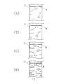
- FIG. 4 is an explanatory view illustrating the change over time of the surface of the test sample in a front view.
- FIG. 5 is a graph illustrating the change over time in the volume of cracks that have occurred.
- FIG. 6 is a graph showing an example of the change over time in the area of the generated crack.
- FIG. 7 is an explanatory diagram schematically illustrating the data stored in the storage unit.
- FIG. 8 is an explanatory view illustrating a modified example of the test tank of FIG. 3 in plan view.
- the ozone deterioration evaluation system 1 of the present invention (hereinafter, referred to as evaluation system 1) illustrated in FIGS. 1 to 3 is used for the ozone deterioration evaluation method of the vulcanized rubber material of the present invention.
- the evaluation system 1 includes a test tank 2, a fixed frame 3 to which a test sample S of a vulcanized rubber material to be evaluated is attached, and an ozone injector 4. Further, the system 1 includes a laser sensor 5 placed opposite to the surface of the test sample S placed in the test tank 2, a storage unit 9 to which the detection data 5x of the laser sensor 5 is input, and a predetermined unit. And an arithmetic unit 8 for executing a detection data processing program.
- a computer having a CPU and a memory may be used as the arithmetic unit 8 and the storage unit 9.
- a monitor 7 is connected to this computer, and the monitor 7 displays the detection data 5x (5a, 5b, 5c%) And the calculation result by the calculation device 8.
- the system 1 of this embodiment further includes at least one camera device 6.
- Digital image data 6x (6a, 6b, 6c...) Taken by the camera device 6 is input to the storage unit 9. Further, a predetermined image data processing program is executed by the arithmetic unit 8. The image data 6x is displayed on the monitor 7.
- test sample S various dumbbell-shaped samples specified by JIS can be used. Alternatively, a cut sample of an actual rubber product, an approximate model of the rubber product, or the like can be used.
- a marker M may be attached to the surface of the test sample S.
- the marker M for example, a marking having a color different from that of the surrounding surface is used.
- the markers M are attached to the positions separated by a predetermined distance, the tensile strain occurring in the test sample S can be easily grasped by checking the distance between the markers M.
- two test samples S are attached to the fixed frame 3 and the ozone resistance of the two test samples S is measured at the same time, but the number of test samples S may be one or plural.
- each test sample S may have the same specifications or different specifications.
- the test tank 2 is a container that can be hermetically sealed, and ozone Z is supplied from the ozone injector 4 so that the ozone concentration in the test tank 2 can be set to a desired concentration.
- the ozone injector 4 is installed in a circulation path for supplying ozone Z, and the circulation path is provided with an exhaust pipe and the like via an exhaust purification filter and a switching valve 4a.
- a transparent resin is used in a range facing the laser sensor 5 and the camera device 5 (a range required for the laser sensor 5 and the camera device 6 to detect and photograph the surface of the test sample S). Adopt glass.
- the test sample S is placed under preset placement conditions. In this embodiment, both longitudinal ends of the test sample S are sandwiched by the grips 3a. For example, by mounting and fixing the test sample S on the fixed frame 3, the test sample S is maintained in a state in which a predetermined tensile strain is applied. Alternatively, a predetermined bending strain is applied to the test sample S to keep it in a bent state.
- the tensile strain applied to the test sample S may be set in accordance with the test method of JIS K 6259-1:2015.
- the test sample S can be arranged in a state (form) in which the rubber product is actually used.
- the laser sensor 5 measures the distance from the laser sensor 5 to the surface of the test sample S over time with respect to the preset detection range of the surface of the test sample S placed in the test tank 2. It detects and acquires detection data 5x.
- a sensor that receives the laser light applied to the surface of the test sample S and detects the distance is used as the laser sensor 5.
- a moving mechanism for moving the laser sensor 5 is provided so as to cover the detection range.
- the camera device 6 acquires the image data 6x by taking a fixed point image of the surface of the test sample S placed in the test tank 2 over time.
- the camera device 6 may be provided with two types, a still image camera device and a moving image camera device, but one of either one may be provided.
- the detection range of the laser sensor 5 and the imaging range of the camera device 6 may be the same range on the surface of the test sample S.
- the range between the markers M is set as the detection range and the shooting range.
- a predetermined detection data processing program is installed in the storage unit 9, and a database 10 in which the detection data 5x is stored is stored.
- the detection data processing program the detection position and size (distance) of the detection data 5x are specified, and the arrangement and size (length, length) of the ozone crack Cr (hereinafter, referred to as crack Cr) on the surface of the test sample S are specified.
- a program for calculating volume, area) can be exemplified.
- the size of the detection data 5x differs between the area where the crack Cr is generated and the area where the crack Cr is not generated. That is, the distance between the surface of the test sample S and the laser sensor 5 before the crack Cr is generated is known.
- the detection data 5x is larger in the crack Cr generation range than in the non-generation range. Therefore, by executing this detection data processing program by the arithmetic unit 8, the generation range and the non-generation range of the crack Cr are discriminated and recognized based on the size of the detection data 5x, and their arrangement, volume and area. Is specified and calculated.
- the storage unit 9 also stores a database 10 in which a predetermined image data processing program is installed and the image data 6x is stored.
- An example of this image data processing program is a program that specifies and calculates the arrangement and area of each of the shades (colors) of the image data 6x.
- the shade (color) of the ozone crack Cr hereinafter referred to as crack Cr
- the range where the crack Cr is generated becomes darker than the range where the crack Cr is not generated.
- the generation range and the non-generation range of the crack Cr are distinguished and recognized based on the light and shade (color) in the image data 6x, and the arrangement and area thereof are specified and calculated. To be done.
- the image data processing program includes a sharpening program for the image data 6x.
- the sharpening program performs, for example, processing for making the image data 6 high-definition/fine, improving contrast, and the like so as to make it difficult to see the image data 6x. This makes it easy to distinguish the range where the crack Cr is generated and the range where the crack Cr is not generated on the basis of the shading (color) of the image data 6x, which is advantageous in accurately specifying and calculating the arrangement and area of the crack Cr.
- the test sample S is placed in the test tank 2 having a predetermined ozone concentration under preset placement conditions.
- the inside of the test tank 2 is maintained at a predetermined ozone concentration.
- the ozone concentration to be maintained is 500 ⁇ 50 ppb (50 ⁇ 5 pphm), 250 ⁇ 50 ppb (25 ⁇ 5 pphm), 1000 ⁇ 100 ppb (100 ⁇ 10 pphm), 2000 according to the test method of JIS K 6259-1:2015. It may be set to ⁇ 200 ppb (200 ⁇ 20 pphm). It is also possible to set the ozone concentration close to the conditions under which the rubber product is actually used.
- the internal temperature and internal humidity of the test tank 2 are set within an appropriate desired range. These conditions should conform to the test method of JIS K 6259-1:2015. Therefore, it is preferable that the inside of the test tank 2 is 40 ⁇ 2° C. and the relative humidity at the internal temperature is 65% or less, but the internal temperature and the internal humidity can be set to be close to the conditions under which the rubber product is actually used. ..
- the detection data 5x can be set to be acquired 2, 4, 8, 24, 48, 72, 96 hours after the start of the test in accordance with the test method of JIS K 6259-1:2015.
- the time interval for acquiring 5x can be set arbitrarily.
- the surface of the test sample S placed in the test tank 2 is subjected to fixed point imaging with time by at least one camera device 6 to acquire image data 6x.
- the image data 6x can be set to be acquired 2, 4, 8, 24, 48, 72, 96 hours after the start of the test in accordance with the test method of JIS K 6259-1:2015.
- the time interval for acquiring 6x can be set arbitrarily.
- the image data 6x may be acquired at intervals of, for example, 10 minutes or 1 hour.
- the image data 6x may be set to be sequentially acquired, for example. Note that the detection data 5x and the image data 6x may be acquired at substantially the same timing in order to clarify the relationship between them.
- the acquired detection data 5x and image data 6x are sequentially input and stored in the storage unit 9.
- the detection data 5x and the image data 6x input to the arithmetic unit 8 are displayed on the monitor 7.
- FIG. 4 shows image data 6a, 6b, 6c, 6d acquired in time series in the order of (A), (B), (C), and (D).
- the change in the surface state of the test sample S between a plurality of time points is grasped. For example, as the change in the surface state of the test sample S, the total number of cracks Cr generated per unit area, the total volume of cracks Cr generated per unit area, the total area of cracks Cr generated per unit area, among these, At least one of the judgment items can be calculated by the arithmetic unit 8 based on the detection data 5x.
- the total number of cracks Cr generated per unit area, the total area of cracks Cr generated per unit area, the maximum length of the generated cracks Cr, the average of the generated cracks Cr is the image data 6x. It can also be calculated by the arithmetic unit 8 based on When acquiring the detection data 5x and the image data 6x, it is determined in advance which data should be used in order to calculate the above-mentioned determination items.
- FIG. 5 illustrates the change over time in the total volume of cracks Cr generated per unit area of test samples S (S1, S2, S3) having different rubber specifications. Since the depth of the crack Cr can also be detected by the laser sensor 5, it is possible to easily obtain the change over time in the volume as a calculation result by the calculation device 8.
- FIG. 6 illustrates a change over time in the total area of cracks Cr generated per unit area of test samples S (S1, S2, S3) having different rubber specifications. In this way, it is possible to obtain the calculation result of the calculation device 8 for a desired judgment item.
- the detection data 5x and the image data 6x are acquired while the test sample S is kept in the test tank 2 having a predetermined ozone concentration. Then, since the change in the surface state of the test sample S between a plurality of time points is grasped based on the acquired detection data 5x and image data 6x, the test sample S is tested every time the surface state of the test sample S is confirmed. The work of putting in and out of the tank 2 becomes unnecessary. The work of observing the surface of the test sample S with a microscope is also unnecessary.
- the depth and volume of the crack Cr can be grasped. Therefore, according to the present invention, it is possible to accurately grasp the change over time in ozone deterioration of the vulcanized rubber material forming the test sample S while reducing the number of work steps.
- the image data 6x is digital data that is easy to analyze, by analyzing the image data 6x acquired at different times, it is possible to grasp the change over time of the surface state of the test sample S. Therefore, by acquiring the detection data 5x and the image data 6x as in this embodiment, the temporal change of the surface state of the test sample S can be more accurately grasped.
- the respective detection data 5x and image data 6x are stored in the database 10 of the storage unit 9.
- Index data 11x (11a, 11b, 11c%) And 12x (12a, 12b, 12c%) Indicating the degree of progress of ozone deterioration are stored in the storage unit 9 in advance. Then, by comparing the respective detection data 5x and the index data 11x by the arithmetic unit 8, the degree of progress of ozone deterioration based on the index data 11x with respect to the surface state of the test sample S in the respective detection data 5x. Can also be determined automatically.
- the progress of ozone deterioration based on the index data 11x is performed with respect to the surface state of the test sample S in the respective image data 6x. It is also possible to judge the degree automatically.
- index data 11x for example, data divided into a plurality according to the volume size and depth of the crack Cr is used. For example, if the volume (depth) of the crack Cr is a1 or more and less than a2, it is A classification, if a2 or more and less than a3 is B classification, if it is a3 or more and less than a4 is C classification,... It is stored in the section 9.
- the computing device 8 selects index data 11x that matches the respective detection data 5x. Accordingly, the surface state of the test sample S in the detection data 5x is determined to be the degree of progress of ozone deterioration classified by the selected index data 11x.
- index data 12x for example, the index described in the Annex (normative) crack evaluation method of JIS K 6259-1:2015 is used. That is, the image data corresponding to the 15 sections A-1 to A-5, B-1 to B-5, and C-1 to C-5 described in this annex are stored in the storage unit 9 as index data 12x.
- the computing device 8 selects the index data 12x having the highest degree of coincidence with the respective image data 6x. As a result, the surface state of the test sample S in the image data 6x is determined to be the degree of ozone deterioration indicated by the index data 12x selected to have the highest similarity between the images.
- the camera device 6 If two types of camera device, a moving image camera device and a still image camera device, are used as the camera device 6, it becomes easier to grasp the ozone deterioration state and change condition in more detail. Similarly, in order to grasp the state of ozone deterioration and the degree of change in more detail, by using the processed data obtained by sharpening the respective image data 6x, the surface state of the test sample S between a plurality of time points is determined. You should understand the changes.
- a through hole 2a is formed in the test tank 2, and the taking lens unit 6A of at least one camera device 6 is inserted into the through hole 2a from the outer side to the inner side of the test tank 2. You can also The gap between the outer peripheral surface of the photographing lens unit 6A and the through hole 2a is sealed with the sealing material 2b.
- the main body of the camera device 6 is not arranged inside the test tank 2. Therefore, it is advantageous to obtain clearer image data 6x while avoiding the main body of the camera device 6 being invaded by ozone Z.
- the detection data 5x and the image data 6x should be sequentially input and stored in a storage unit 9 installed in a management office or the like, which is remote from the test tank 2, the laser sensor 5, and the camera device 6, through an internet line or the like. You can Therefore, the change over time in ozone deterioration of the surface (vulcanized rubber material) of the test sample S can be grasped at a management office or the like.
- Evaluation System Test Tank 2a Through Hole 2b Sealing Material 3 Fixed Frame 3a Gripping Part 4 Ozone Injector 4a Switching Valve 5 Laser Sensor 5x Detection Data 6 Camera Device 6A Photographic Lens Part 6x Image Data 7 Monitor 8 Computing Device 9 Storage Unit 10 Database 11x, 12x Index data S Test sample M Marker Cr Crack Z Ozone
Landscapes
- Life Sciences & Earth Sciences (AREA)
- Chemical & Material Sciences (AREA)
- Health & Medical Sciences (AREA)
- Physics & Mathematics (AREA)
- General Physics & Mathematics (AREA)
- Engineering & Computer Science (AREA)
- Immunology (AREA)
- Pathology (AREA)
- Analytical Chemistry (AREA)
- Biochemistry (AREA)
- General Health & Medical Sciences (AREA)
- Medicinal Chemistry (AREA)
- Food Science & Technology (AREA)
- Biodiversity & Conservation Biology (AREA)
- Ecology (AREA)
- Environmental & Geological Engineering (AREA)
- Environmental Sciences (AREA)
- Quality & Reliability (AREA)
- Computer Vision & Pattern Recognition (AREA)
- Theoretical Computer Science (AREA)
- Testing Resistance To Weather, Investigating Materials By Mechanical Methods (AREA)
Abstract
作業工数を軽減しつつ、精度よくオゾン劣化の経時変化を把握できる加硫ゴム材料のオゾン劣化評価方法および評価システムを提供する。所定のオゾン濃度の試験槽2の中に、加硫ゴム材料の試験サンプルSを予め設定された配置条件で固定フレーム3に取付けて配置し、この試験槽2の中に配置された状態の試験サンプルSの表面に対置させたレーザセンサ5により、経時的にレーザセンサ5から試験サンプルSの表面までの距離を検知してその検知データ5xを取得し、複数の時点間での試験サンプルSの表面状態の変化を、取得した検知データ5xを演算装置8によって分析することで把握する。
Description
本発明は、加硫ゴム材料のオゾン劣化評価方法および評価システムに関し、さらに詳しくは、作業工数を軽減しつつ精度よくオゾン劣化の経時変化を把握できる加硫ゴム材料のオゾン劣化評価方法および評価システムに関するものである。
タイヤ等の様々な加硫ゴム製品には、いわゆるオゾンクラックが生じる。オゾンクラックが大きく成長すると、そのゴム製品の性能や耐用期間に影響する。そのため、加硫ゴムのオゾン劣化を評価する方法として、JIS K 6259-1:2015に規定されている「加硫ゴム及び熱可塑性ゴム-耐オゾン性の求め方」に規定されている静的オゾン劣化試験が広く知られている。この試験方法では、所定のオゾン濃度雰囲気下に配置された試験サンプルの劣化状態を試験担当者が所定時間毎にチェックする。即ち、試験サンプル表面の亀裂の有無、亀裂の状態、亀裂の大きさ等を、試験担当者が所定時間毎に記録する必要があるので相応の作業工数を要する。また、試験担当者の感覚的な判断の相違に起因して、耐オゾン性の評価結果にばらつきが生じる。
定量的に加硫ゴムのオゾン劣化を評価する方法も提案されている(例えば、特許文献1参照)。特許文献1で提案されている評価方法では、一定の伸長を加えた加硫ゴム試験片をオゾン雰囲気下に所定時間曝した後、その伸長状態のまま、試験片の表面状態を光学顕微鏡等によって観察する。そして、試験片の表面の撮影範囲を特定した後、ビデオカメラ等でその撮影範囲を撮影する。次いで、撮影した画像を処理することで、撮影範囲の面積に対するオゾンクラックの面積の割合を算出する(明細書第2ページ左上欄~右上欄)。この方法では、発生したオゾンクラックの定量的な面積変化を把握することができる。しかしながら、顕微鏡等で試験片の表面状態を観察する作業を行う必要がある。また、この顕微鏡等による観察を行う際には、オゾンが充填されている試験槽から試験片を取り出す作業等も必要になる。それ故、作業工数を軽減しつつ精度よくオゾン劣化の経時変化を把握するには改善の余地がある。
本発明の目的は、作業工数を軽減しつつ精度よくオゾン劣化の経時変化を把握できる加硫ゴム材料のオゾン劣化評価方法および評価システムを提供することにある。
上記目的を達成するため本発明の加硫ゴム材料のオゾン劣化評価方法は、所定のオゾン濃度の試験槽の中に、加硫ゴム材料の試験サンプルを予め設定された配置条件で配置して、前記試験サンプルの表面状態の経時変化を把握する加硫ゴム材料のオゾン劣化評価方法において、前記試験槽の中に配置された状態の前記試験サンプルの表面に対置させたレーザセンサにより、経時的に前記レーザセンサから前記表面までの距離を検知してその検知データを取得し、前記検知データに基づいて、複数の時点間での前記試験サンプルの表面状態の変化を把握することを特徴とする。
本発明の加硫ゴム材料のオゾン劣化評価システムは、所定のオゾン濃度に維持される試験槽と、この試験槽の中に加硫ゴム材料の試験サンプルを予め設定された配置条件で配置する固定フレームとを備えた加硫ゴム材料のオゾン劣化評価システムにおいて、前記試験槽の中に配置された状態の前記試験サンプルの表面に対置されたレーザセンサと、このレーザセンサにより経時的に検知されるこのレーザセンサから前記表面までの距離の検知データが入力される記憶部と、所定の検知データ処理プログラムを行う演算装置とを備えて、前記検知データに基づいて前記演算装置により、複数の時点間での前記試験サンプルの表面状態の変化具合を算出する構成にしたことを特徴とする。
本発明によれば、評価対象となる加硫ゴム材料の試験サンプルを、所定のオゾン濃度の試験槽の中に配置した状態のままで、その試験サンプルの表面に対置させたレーザセンサにより、経時的にレーザセンサからその試験サンプルの表面までの距離を検知してその検知データを取得する。そして、取得した検知データに基づいて、複数の時点間での試験サンプルの表面状態の変化を把握するので、試験サンプルの表面状態を確認する度に試験サンプルを試験槽に対して出し入れする作業は不要になる。また、試験サンプルの表面を顕微鏡等によって観察する作業も不要になる。そして、試験サンプルの表面状態の経時変化は、取得したそれぞれの検知データに基づいて把握できるので、オゾンクラックの平面的な大きさだけでなく、深さや体積も把握できる。そのため、本発明によれば、作業工数を軽減しつつ精度よくオゾン劣化の経時変化を把握することが可能になる。
以下、本発明の加硫ゴム材料のオゾン劣化評価方法および評価システムを、図に示した実施形態に基づいて説明する。
本発明の加硫ゴム材料のオゾン劣化評価方法には、図1~図3に例示する本発明のオゾン劣化評価システム1(以下、評価システム1という)が使用される。この評価システム1は、試験槽2と、評価対象となる加硫ゴム材料の試験サンプルSが取り付けられる固定フレーム3と、オゾン注入器4とを有している。さらに、このシステム1は、試験槽2の中に配置された状態の試験サンプルSの表面に対置されたレーザセンサ5と、レーザセンサ5による検知データ5xが入力される記憶部9と、所定の検知データ処理プログラムを行う演算装置8とを備えている。演算装置8および記憶部9としては、CPUおよびメモリを備えたコンピュータを用いればよい。このコンピュータにモニタ7が接続されて、モニタ7には検知データ5x(5a、5b、5c・・・)や演算装置8による演算結果などが表示される。
この実施形態のシステム1は、さらに、少なくとも1台のカメラ装置6を有している。
カメラ装置6により撮影されたデジタル画像データ6x(6a、6b、6c・・・)は記憶部9に入力される。また、所定の画像データ処理プログラムが演算装置8により実行される。モニタ7には画像データ6xが表示される。
カメラ装置6により撮影されたデジタル画像データ6x(6a、6b、6c・・・)は記憶部9に入力される。また、所定の画像データ処理プログラムが演算装置8により実行される。モニタ7には画像データ6xが表示される。
試験サンプルSとしては、JISで規定されている各種ダンベル形状のサンプルを用いることができる。或いは、実際のゴム製品のカットサンプルや、ゴム製品の近似モデル等を用いることもできる。試験サンプルSの表面にはマーカMを付すとよい。マーカMとしては、例えば、周囲の表面と異なる色のマーキング等を用いる。所定間隔で離間させた位置にマーカMを付すと、マーカMどうしの離間距離を確認することで、試験サンプルSに生じている引張歪みを把握し易くなる。この実施形態では、2つの試験サンプルSが固定フレーム3に取付けられ、同時に2つの試験サンプルSの耐オゾン性が測定されるが、試験サンプルSは単数でも複数でもよい。複数の試験サンプルSの耐オゾン性が同時に測定される場合は、それぞれの試験サンプルSは同じ仕様であっても異なる仕様であってもよい。
試験槽2は内部を密閉できる容器であり、オゾン注入器4からオゾンZが供給されて試験槽2の中のオゾン濃度は所望濃度に設定可能になっている。例えば、オゾンZを供給する循環路にオゾン注入器4が設置されて、その循環路には排気浄化フィルタや切換え弁4aを介して排気管等が備わる。試験槽2の壁面のうち、レーザセンサ5、カメラ装置5と対向する範囲(レーザセンサ5、カメラ装置6が試験サンプルSの表面を検知、撮影するために必要な範囲)には透明な樹脂やガラスを採用する。
固定フレーム3は、試験サンプルSを予め設定された配置条件で配置する。この実施形態では、試験サンプルSの長手方向両端部が把持部3aによって挟持されている。例えば、試験サンプルSを固定フレーム3に取付けて固定することにより、試験サンプルSに所定の引張歪みが付与されている状態に維持する。或いは、試験サンプルSに所定の曲げ歪みが付与されて屈曲状態に維持にする。JIS K 6259-1:2015の試験方法に準拠して、試験サンプルSに付与する引張歪みを設定するとよい。ゴム製品が実際に使用される状態(形態)で試験サンプルSを配置することもできる。
レーザセンサ5は、試験槽2の中に配置された状態の試験サンプルSの予め設定された表面の検知範囲に対して、レーザセンサ5から試験サンプルSのその表面のまでの距離を経時的に検知して検知データ5xを取得する。レーザセンサ5としては、試験サンプルSの表面に照射したレーザ光を受光して距離を検知するセンサを用いる。この検知範囲を網羅するようにレーザセンサ5を移動させる移動機構が備わっている。
カメラ装置6は、試験槽2の中に配置された状態の試験サンプルSの表面を、経時的に定点撮影して画像データ6xを取得する。カメラ装置6としては、静止画用カメラ装置と動画用カメラ装置の2種類を備えることもできるが、いずれか一方の1種類でもよい。レーザセンサ5による検知範囲と、カメラ装置6による撮影範囲とは、試験サンプルSの表面の同じ範囲にするとよい。例えば、マーカMどうしの間の範囲をこの検知範囲、撮影範囲に設定する。
記憶部9には、所定の検知データ処理プログラムがインストールされていて、検知データ5xが記憶されるデータベース10が格納されている。この検知データ処理プログラムとしては、検知データ5xの検知位置、大きさ(距離)を特定して、試験サンプルSの表面上のオゾンクラックCr(以下、クラックCrという)の配置やサイズ(長さ、体積、面積)を算出するプログラムを例示できる。
クラックCrの発生範囲と非発生範囲とは検知データ5xの大きさが相違する。即ち、クラックCrが発生する前の試験サンプルSの表面とレーザセンサ5との離間距離は既知である。そして、クラックCrが発生すると、レーザセンサ5から照射されるレーザ光はクラックCrの奥にまで入り込んでから反射する。したがって、クラックCrの発生範囲は非発生範囲に比して検知データ5xが大きくなる。それ故、演算装置8によってこの検知データ処理プログラムを実行することで、クラックCrの発生範囲と非発生範囲とが、検知データ5xの大きさに基づいて区別して認識され、その配置、体積や面積が特定、算出される。
また、この記憶部9には、所定の画像データ処理プログラムがインストールされていて、画像データ6xが記憶されるデータベース10が格納されている。この画像データ処理プログラムとしては、画像データ6xの濃淡(色彩)の程度毎に、その配置や面積を特定、算出するプログラムを例示できる。試験サンプルSの表面上のオゾンクラックCr(以下、クラックCrという)の発生範囲と非発生範囲とは画像データ6x上では濃淡(色彩)が相違する。一般的には、クラックCrの発生範囲は非発生範囲に比して濃色になる。したがって、演算装置8によってこのプログラムを実行することで、クラックCrの発生範囲と非発生範囲とが、画像データ6xにおける濃淡(色彩)に基づいて区別して認識され、その配置や面積が特定、算出される。
この実施形態では、画像データ処理プログラムに、画像データ6xの鮮明化プログラムが含まれている。この鮮明化プログラムは、例えば、画像データ6の高精細・微細化、コントラストの改善などの処理を行なって、見え難い画像データ6xを見易くする処理を行う。これにより、画像データ6xの濃淡(色彩)に基づいて、クラックCrの発生範囲と非発生範囲とが区別して認識易くなり、その配置や面積を高精度で特定、算出するには有利になる。
次に、試験サンプルSのオゾン劣化を評価する手順の一例を説明する。
図1~図3に例示するように、所定のオゾン濃度の試験槽2の中に試験サンプルSを予め設定された配置条件で配置する。試験槽2の中は所定のオゾン濃度に維持される。維持されるオゾン濃度は、JIS K 6259-1:2015の試験方法に準拠して、500±50ppb(50±5pphm)や250±50ppb(25±5pphm)、1000±100ppb(100±10pphm)、2000±200ppb(200±20pphm)に設定するとよい。ゴム製品が実際に使用される条件に近似したオゾン濃度に設定することもできる。
試験槽2の内部温度や内部湿度は、適宜の所望範囲に設定される。これらの条件は、JIS K 6259-1:2015の試験方法に準拠するとよい。したがって、試験槽2の内部は40±2℃、内部温度における相対湿度は65%以下にするとよいが、ゴム製品が実際に使用される条件に近似した内部温度、内部湿度に設定することもできる。
そして、試験槽2の中に配置された状態の試験サンプルSの表面の検知範囲について、レーザセンサ5から試験サンプルSの表面までの距離を検知して、検知データ5xを取得する。検知データ5xは、JIS K 6259-1:2015の試験方法に準拠して、試験開始から2、4、8、24、48、72、96時間後に取得する設定にすることもできるが、検知データ5xを取得する時間間隔は任意に設定できる。
この実施形態では、さらに、試験槽2の中に配置された状態の試験サンプルSの表面を、少なくとも1台のカメラ装置6により経時的に定点撮影して画像データ6xを取得する。画像データ6xは、JIS K 6259-1:2015の試験方法に準拠して、試験開始から2、4、8、24、48、72、96時間後に取得する設定にすることもできるが、画像データ6xを取得する時間間隔は任意に設定できる。静止画用カメラ装置の場合は、画像データ6xの取得を例えば、10分間隔或いは1時間間隔に行う設定にすることもできる。動画用カメラ装置の場合は、画像データ6xの取得を例えば、逐次行う設定にすることもできる。尚、検知データ5xと画像データ6xは、お互いの関連性を明確にするため、実質的に同じタイミングで取得するとよい。
取得された検知データ5x、画像データ6xは記憶部9に逐次、入力されて記憶される。演算装置8に入力された検知データ5x、画像データ6xはモニタ7に表示される。
試験サンプルSは所定のオゾン濃度下に配置され続けることにより、試験サンプルSのゴム分子の化学結合が切断される。これに起因して図4に例示するように、試験サンプルSの表面にはクラックCrが発生するので表面状態が変化する。図4は、(A)、(B)、(C)、(D)の順の時系列で取得した画像データ6a、6b、6c、6dを示している。
そこで、取得した検知データ5x、画像データ6xに基づいて、複数の時点間での試験サンプルSの表面状態の変化を把握する。例えば、試験サンプルSの表面状態の変化として、単位面積当たりに発生したクラックCrの総数、単位面積当たりに発生したクラックCrの総体積、単位面積当たりに発生したクラックCrの総面積、これらのうちの少なくとも1つの判断項目が、検知データ5xに基づいて、演算装置8により算出することもできる。
また、試験サンプルSの表面状態の変化として、単位面積当たりに発生したクラックCrの総数、単位面積当たりに発生したクラックCrの総面積、発生したクラックCrの最大長さ、発生したクラックCrの平均長さ、発生したクラックCrの最小長さ、特定の1つまたは2つのクラックCrに注目してそのクラックCrの長さ(または面積)、これらのうちの少なくとも1つの判断項目が、画像データ6xに基づいて、演算装置8により算出することもできる。検知データ5xおよび画像データ6xを取得する場合は、上記の判断項目を算出するためにいずれのデータを優先して使用するかを決定しておく。
図5は、異なるゴム仕様の試験サンプルS(S1、S2、S3)の単位面積当たりに発生したクラックCrの総体積の経時変化を例示している。レーザセンサ5により、クラックCrの深さも検知できるので、その体積についての経時変化を演算装置8による演算結果として容易に得ることができる。
図6は、異なるゴム仕様の試験サンプルS(S1、S2、S3)の単位面積当たりに発生したクラックCrの総面積の経時変化を例示している。このように所望の判断項目についても演算装置8による演算結果を得ることができる。
上述したとおり、試験サンプルSを、所定のオゾン濃度の試験槽2の中に配置した状態のままで、検知データ5x、画像データ6xを取得する。そして、取得した検知データ5x、画像データ6xに基づいて、複数の時点間での試験サンプルSの表面状態の変化を把握するので、試験サンプルSの表面状態を確認する度に試験サンプルSを試験槽2に対して出し入れする作業は不要になる。試験サンプルSの表面を顕微鏡等によって観察する作業も不要になる。
しかも、検知データ5xによれば、クラックCrの深さや体積も把握できる。そのため、本発明によれば、作業工数を軽減しつつ精度よく、その試験サンプルSを形成している加硫ゴム材料のオゾン劣化の経時変化を把握することが可能になる。
画像データ6xは分析し易いデジタルデータなので、異なる時点で取得した画像データ6xを分析することで、試験サンプルSの表面状態の経時変化を把握できる。したがって、この実施形態のように、検知データ5xと画像データ6xを取得することで、試験サンプルSの表面状態の経時変化を一段と精度よく把握できる。
図7に例示するように、それぞれの検知データ5x、画像データ6xは記憶部9のデータベース10に記憶される。この記憶部9には、オゾン劣化の進行度を示す指標データ11x(11a、11b、11c・・・)、12x(12a、12b、12c・・・)を予め記憶させておく。そして、それぞれの検知データ5xと指標データ11xとを演算装置8により比較することで、それぞれの検知データ5xでの試験サンプルSの表面状態に対して、この指標データ11xに基づくオゾン劣化の進行度を自動的に判断することもできる。同様に、それぞれの画像データ6xと指標データ11xとを演算装置8により比較することで、それぞれの画像データ6xでの試験サンプルSの表面状態に対して、この指標データ11xに基づくオゾン劣化の進行度を自動的に判断することもできる。
この指標データ11xとして例えば、クラックCrの体積の大きさや深さの程度ごとに複数に区分されたデータを用いる。例えば、クラックCrの体積(深さ)がa1以上a2未満はA区分、a2以上a3未満はB区分、a3以上a4未満はC区分、・・・のように区分したデータを指標データ11xとして記憶部9に記憶させておく。演算装置8によって、それぞれの検知データ5xが合致する指標データ11xが選択される。これにより、その検知データ5xでの試験サンプルSの表面状態は、選択された指標データ11xが区分するオゾン劣化の進行度であると判断される。
指標データ12xとして例えば、JIS K 6259-1:2015の附属書(規定)き裂の評価方法に記載されている指標を用いる。即ち、この附属書に記載されているA-1~A-5、B-1~B-5、C-1~C-5の15区分に対応する画像データを指標データ12xとして記憶部9に記憶させておく。演算装置8によって、それぞれの画像データ6xとの一致度が最も高い指標データ12xが選択される。これにより、その画像データ6xでの試験サンプルSの表面状態は、画像どうしの類似性が最も高いと選択された指標データ12xが示すオゾン劣化の進行度であると判断される。
カメラ装置6として、動画用カメラ装置と静止画用カメラ装置の2種類を使用すると、より詳細にオゾン劣化の状況、変化具合を把握し易くなる。また、同様に、より詳細にオゾン劣化の状況、変化具合を把握するには、それぞれの画像データ6xを鮮明化処理した処理データを用いて、複数の時点間での試験サンプルSの表面状態の変化を把握するとよい。
カメラ装置6と試験サンプルSの間に試験槽2の壁面が介在していると、この壁面で光が反射する等に起因して、画像データ6xにノイズが入る可能性がある。そこで、図8に例示するように、試験槽2に貫通孔2aを形成して、この貫通孔2aに少なくとも1台のカメラ装置6の撮影レンズ部6Aを試験槽2の外側から内側に挿入させることもできる。撮影レンズ部6Aの外周面と貫通孔2aとのすき間はシール材2bシールした状態にする。
この実施形態では、カメラ装置6の本体は、試験槽2の内部に配置されない。したがって、カメラ装置6の本体がオゾンZによって侵されることを回避しつつ、より鮮明な画像データ6xを取得するには有利になる。
それぞれの検知データ5x、画像データ6xは、試験槽2やレーザセンサ5、カメラ装置6から離れた管理事務所などに設置された記憶部9に、インターネット回線等を通じて、逐次、入力、記憶することができる。そのため、管理事務所等において、試験サンプルSの表面(加硫ゴム材料)のオゾン劣化の経時変化を把握できる。
1 評価システム
2 試験槽
2a 貫通孔
2b シール材
3 固定フレーム
3a 把持部
4 オゾン注入器
4a 切換え弁
5 レーザセンサ
5x 検知データ
6 カメラ装置
6A 撮影レンズ部
6x 画像データ
7 モニタ
8 演算装置
9 記憶部
10 データベース
11x、12x 指標データ
S 試験サンプル
M マーカ
Cr クラック
Z オゾン
2 試験槽
2a 貫通孔
2b シール材
3 固定フレーム
3a 把持部
4 オゾン注入器
4a 切換え弁
5 レーザセンサ
5x 検知データ
6 カメラ装置
6A 撮影レンズ部
6x 画像データ
7 モニタ
8 演算装置
9 記憶部
10 データベース
11x、12x 指標データ
S 試験サンプル
M マーカ
Cr クラック
Z オゾン
Claims (9)
- 所定のオゾン濃度の試験槽の中に、加硫ゴム材料の試験サンプルを予め設定された配置条件で配置して、前記試験サンプルの表面状態の経時変化を把握する加硫ゴム材料のオゾン劣化評価方法において、
前記試験槽の中に配置された状態の前記試験サンプルの表面に対置させたレーザセンサにより、経時的に前記レーザセンサから前記表面までの距離を検知してその検知データを取得し、前記検知データに基づいて、複数の時点間での前記試験サンプルの表面状態の変化を把握することを特徴とする加硫ゴム材料のオゾン劣化評価方法。 - 前記試験サンプルの表面状態の変化として、単位面積当たりに発生したオゾンクラックの総数、単位面積当たりに発生したオゾンクラックの総体積、単位面積当たりに発生したオゾンクラックの総面積、のうちの少なくとも1つの判断項目を把握する請求項1に記載の加硫ゴム材料のオゾン劣化評価方法。
- それぞれの前記検知データを記憶部のデータベースに記憶し、前記記憶部に記憶されているオゾン劣化の進行度を示す指標データと、それぞれの前記検知データとを演算装置によって比較することで、それぞれの前記検知データでの前記試験サンプルの表面状態に対して前記指標データに基づくオゾン劣化の進行度を自動的に判断する請求項1または2に記載の加硫ゴム材料のオゾン劣化評価方法。
- 前記試験サンプルの表面を、少なくとも1台のカメラ装置により経時的に定点撮影してデジタル画像データを取得し、前記画像データに基づいて、複数の時点間での前記試験サンプルの表面状態の変化を把握する請求項1~3のいずれかに記載の加硫ゴム材料のオゾン劣化評価方法。
- それぞれの前記画像データを鮮明化処理した処理データを用いて、複数の時点間での前記試験サンプルの表面状態の変化を把握する請求項4に記載の加硫ゴム材料のオゾン劣化評価方法。
- それぞれの前記画像データを前記記憶部のデータベースに記憶し、前記記憶部に記憶されているオゾン劣化の進行度を示す指標データと、それぞれの前記画像データとを演算装置によって比較することで、それぞれの前記画像データでの前記試験サンプルの表面状態に対して前記指標データに基づくオゾン劣化の進行度を自動的に判断する請求項4または5に記載の加硫ゴム材料のオゾン劣化評価方法。
- 前記試験サンプルの表面状態の変化として、単位面積当たりに発生したオゾンクラックの総数、単位面積当たりに発生したオゾンクラックの総面積、発生したオゾンクラックの最大長さ、発生したオゾンクラックの平均長さ、発生したオゾンクラックの最小長さ、発生した特定のオゾンクラックに注目してそのオゾンンクラックの長さまたは面積、のうちの少なくとも1つの判断項目を把握する請求項4~6のいずれかに記載の加硫ゴム材料のオゾン劣化評価方法。
- 前記試験槽に貫通孔を形成し、この貫通孔に少なくとも1台の前記カメラ装置の撮影レンズ部を前記試験槽の外側から内側に挿入させて、前記撮影レンズ部の外周面と前記貫通孔とのすき間をシールした状態にして、前記画像データを取得する請求項4~7のいずれかに記載の加硫ゴム材料のオゾン劣化評価方法。
- 所定のオゾン濃度に維持される試験槽と、この試験槽の中に加硫ゴム材料の試験サンプルを予め設定された配置条件で配置する固定フレームとを備えた加硫ゴム材料のオゾン劣化評価システムにおいて、
前記試験槽の中に配置された状態の前記試験サンプルの表面に対置されたレーザセンサと、このレーザセンサにより経時的に検知されるこのレーザセンサから前記表面までの距離の検知データが入力される記憶部と、所定の検知データ処理プログラムを行う演算装置とを備えて、前記検知データに基づいて前記演算装置により、複数の時点間での前記試験サンプルの表面状態の変化具合を算出する構成にしたことを特徴とする加硫ゴム材料のオゾン劣化評価システム。
Priority Applications (1)
| Application Number | Priority Date | Filing Date | Title |
|---|---|---|---|
| US17/420,278 US11959850B2 (en) | 2019-01-18 | 2019-11-29 | Evaluation system and method for evaluating vulcanized rubber material deterioration by ozone |
Applications Claiming Priority (4)
| Application Number | Priority Date | Filing Date | Title |
|---|---|---|---|
| JP2019-007344 | 2019-01-18 | ||
| JP2019007344A JP7275594B2 (ja) | 2019-01-18 | 2019-01-18 | 加硫ゴム材料のオゾン劣化評価方法 |
| JP2019007345A JP7275595B2 (ja) | 2019-01-18 | 2019-01-18 | 加硫ゴム材料のオゾン劣化評価システム |
| JP2019-007345 | 2019-04-04 |
Publications (1)
| Publication Number | Publication Date |
|---|---|
| WO2020149029A1 true WO2020149029A1 (ja) | 2020-07-23 |
Family
ID=71613760
Family Applications (1)
| Application Number | Title | Priority Date | Filing Date |
|---|---|---|---|
| PCT/JP2019/046744 Ceased WO2020149029A1 (ja) | 2019-01-18 | 2019-11-29 | 加硫ゴム材料のオゾン劣化評価方法および評価システム |
Country Status (2)
| Country | Link |
|---|---|
| US (1) | US11959850B2 (ja) |
| WO (1) | WO2020149029A1 (ja) |
Families Citing this family (1)
| Publication number | Priority date | Publication date | Assignee | Title |
|---|---|---|---|---|
| WO2020149030A1 (ja) * | 2019-01-18 | 2020-07-23 | 横浜ゴム株式会社 | 加硫ゴム材料のオゾン劣化評価方法および評価システム |
Citations (11)
| Publication number | Priority date | Publication date | Assignee | Title |
|---|---|---|---|---|
| JPH04109142A (ja) * | 1990-08-29 | 1992-04-10 | Kinugawa Rubber Ind Co Ltd | 加硫ゴムのオゾン劣化試験方法 |
| JPH0650909A (ja) * | 1992-07-15 | 1994-02-25 | Mitsuboshi Belting Ltd | ゴムベルトの外観検査装置 |
| JPH0921761A (ja) * | 1993-07-14 | 1997-01-21 | Toshiba Corp | 表面欠陥検査装置 |
| JPH09105720A (ja) * | 1995-10-11 | 1997-04-22 | Nippon Steel Corp | レーザーを用いた材料の評価方法 |
| JPH09329595A (ja) * | 1996-06-12 | 1997-12-22 | Mitsuboshi Belting Ltd | 動力伝動ベルトの残余寿命の推定方法 |
| JP2001059941A (ja) * | 1999-08-24 | 2001-03-06 | Mitsubishi Heavy Ind Ltd | ファイバースコープシステム |
| JP2014126370A (ja) * | 2012-12-25 | 2014-07-07 | Sumitomo Rubber Ind Ltd | 架橋ゴムのクラックの評価方法 |
| JP2015219049A (ja) * | 2014-05-15 | 2015-12-07 | 住友ゴム工業株式会社 | 架橋ゴムの評価方法 |
| JP2017166942A (ja) * | 2016-03-16 | 2017-09-21 | 住友ゴム工業株式会社 | ゴムのクラック検査方法 |
| CN207163880U (zh) * | 2017-09-14 | 2018-03-30 | 湖北高天试验设备有限公司 | 臭氧老化试验箱 |
| CN108956436A (zh) * | 2018-06-20 | 2018-12-07 | 安徽科技学院 | 大气臭氧老化模拟实验装置 |
Family Cites Families (5)
| Publication number | Priority date | Publication date | Assignee | Title |
|---|---|---|---|---|
| JP7275594B2 (ja) * | 2019-01-18 | 2023-05-18 | 横浜ゴム株式会社 | 加硫ゴム材料のオゾン劣化評価方法 |
| JP7275593B2 (ja) * | 2019-01-18 | 2023-05-18 | 横浜ゴム株式会社 | 加硫ゴム材料のオゾン劣化評価システム |
| WO2020149030A1 (ja) * | 2019-01-18 | 2020-07-23 | 横浜ゴム株式会社 | 加硫ゴム材料のオゾン劣化評価方法および評価システム |
| JP7275592B2 (ja) * | 2019-01-18 | 2023-05-18 | 横浜ゴム株式会社 | 加硫ゴム材料のオゾン劣化評価方法 |
| JP7275595B2 (ja) * | 2019-01-18 | 2023-05-18 | 横浜ゴム株式会社 | 加硫ゴム材料のオゾン劣化評価システム |
-
2019
- 2019-11-29 US US17/420,278 patent/US11959850B2/en active Active
- 2019-11-29 WO PCT/JP2019/046744 patent/WO2020149029A1/ja not_active Ceased
Patent Citations (11)
| Publication number | Priority date | Publication date | Assignee | Title |
|---|---|---|---|---|
| JPH04109142A (ja) * | 1990-08-29 | 1992-04-10 | Kinugawa Rubber Ind Co Ltd | 加硫ゴムのオゾン劣化試験方法 |
| JPH0650909A (ja) * | 1992-07-15 | 1994-02-25 | Mitsuboshi Belting Ltd | ゴムベルトの外観検査装置 |
| JPH0921761A (ja) * | 1993-07-14 | 1997-01-21 | Toshiba Corp | 表面欠陥検査装置 |
| JPH09105720A (ja) * | 1995-10-11 | 1997-04-22 | Nippon Steel Corp | レーザーを用いた材料の評価方法 |
| JPH09329595A (ja) * | 1996-06-12 | 1997-12-22 | Mitsuboshi Belting Ltd | 動力伝動ベルトの残余寿命の推定方法 |
| JP2001059941A (ja) * | 1999-08-24 | 2001-03-06 | Mitsubishi Heavy Ind Ltd | ファイバースコープシステム |
| JP2014126370A (ja) * | 2012-12-25 | 2014-07-07 | Sumitomo Rubber Ind Ltd | 架橋ゴムのクラックの評価方法 |
| JP2015219049A (ja) * | 2014-05-15 | 2015-12-07 | 住友ゴム工業株式会社 | 架橋ゴムの評価方法 |
| JP2017166942A (ja) * | 2016-03-16 | 2017-09-21 | 住友ゴム工業株式会社 | ゴムのクラック検査方法 |
| CN207163880U (zh) * | 2017-09-14 | 2018-03-30 | 湖北高天试验设备有限公司 | 臭氧老化试验箱 |
| CN108956436A (zh) * | 2018-06-20 | 2018-12-07 | 安徽科技学院 | 大气臭氧老化模拟实验装置 |
Non-Patent Citations (1)
| Title |
|---|
| ISHIDA, SATOSHI: "Study on remote moniter of weatherproof examination machinery", REPORT OF SAITAMA INDUSTRIAL TECHNOLOGY CENTER, vol. 5, 21 June 2007 (2007-06-21), pages 49 - 52 * |
Also Published As
| Publication number | Publication date |
|---|---|
| US20220091020A1 (en) | 2022-03-24 |
| US11959850B2 (en) | 2024-04-16 |
Similar Documents
| Publication | Publication Date | Title |
|---|---|---|
| CA2989515C (en) | Colour measurement of gemstones | |
| US8393784B2 (en) | Characterization of flaws in composites identified by thermography | |
| RU2665806C2 (ru) | Способ и устройство проверки инспекционной системы для обнаружения поверхностных дефектов | |
| US5631465A (en) | Method of interpreting thermographic data for non-destructive evaluation | |
| US10761032B1 (en) | Apparatus and method for inspection of a film on a substrate | |
| US10684461B2 (en) | Digital pathology system | |
| JP7275592B2 (ja) | 加硫ゴム材料のオゾン劣化評価方法 | |
| US5754524A (en) | Computerized method and system for analysis of an electrophoresis gel test | |
| JP7275595B2 (ja) | 加硫ゴム材料のオゾン劣化評価システム | |
| KR20090076166A (ko) | 화상 분석을 이용한 편광판 얼룩 검사 방법 및 이를 이용한 편광판 얼룩 자동 검사 시스템 | |
| WO2022202198A1 (ja) | 金属表面の粗面処理の評価方法および評価装置 | |
| WO2020149030A1 (ja) | 加硫ゴム材料のオゾン劣化評価方法および評価システム | |
| JP7275594B2 (ja) | 加硫ゴム材料のオゾン劣化評価方法 | |
| CN102842131A (zh) | 一种监测目标物体缺陷的方法及设备 | |
| Kitahashi et al. | Development of robust models for rapid classification of microplastic polymer types based on near infrared hyperspectral images | |
| JP2003506908A (ja) | シーン変化の識別方法およびそのための監視装置 | |
| US12597108B2 (en) | Method and apparatus to perform a wireline cable inspection | |
| JP7275593B2 (ja) | 加硫ゴム材料のオゾン劣化評価システム | |
| US11959850B2 (en) | Evaluation system and method for evaluating vulcanized rubber material deterioration by ozone | |
| KR20100032682A (ko) | 편광판 얼룩 자동 검사 시스템 및 이를 이용한 편광판 얼룩검사 방법 | |
| CN119579511A (zh) | 碳纤维复合材料红外热像分层缺陷检出能力智能评估方法 | |
| JP7085952B2 (ja) | 変化率推定装置、変化率推定方法、状態推定装置及び状態推定方法 | |
| KR101914777B1 (ko) | 생선의 선도를 검사하는 방법 및 이를 위한 장치 | |
| CN116660259A (zh) | 一种基于红外成像的食源性致病菌的快速检测系统 | |
| JP2001235425A (ja) | ペットボトルの偏肉検査方法および装置 |
Legal Events
| Date | Code | Title | Description |
|---|---|---|---|
| 121 | Ep: the epo has been informed by wipo that ep was designated in this application |
Ref document number: 19910897 Country of ref document: EP Kind code of ref document: A1 |
|
| NENP | Non-entry into the national phase |
Ref country code: DE |
|
| 122 | Ep: pct application non-entry in european phase |
Ref document number: 19910897 Country of ref document: EP Kind code of ref document: A1 |