WO2020148975A1 - 車両の制御装置 - Google Patents
車両の制御装置 Download PDFInfo
- Publication number
- WO2020148975A1 WO2020148975A1 PCT/JP2019/043743 JP2019043743W WO2020148975A1 WO 2020148975 A1 WO2020148975 A1 WO 2020148975A1 JP 2019043743 W JP2019043743 W JP 2019043743W WO 2020148975 A1 WO2020148975 A1 WO 2020148975A1
- Authority
- WO
- WIPO (PCT)
- Prior art keywords
- electric machine
- rotating electric
- mode
- vehicle
- motor
- Prior art date
- Legal status (The legal status is an assumption and is not a legal conclusion. Google has not performed a legal analysis and makes no representation as to the accuracy of the status listed.)
- Ceased
Links
Images





Classifications
-
- B—PERFORMING OPERATIONS; TRANSPORTING
- B60—VEHICLES IN GENERAL
- B60K—ARRANGEMENT OR MOUNTING OF PROPULSION UNITS OR OF TRANSMISSIONS IN VEHICLES; ARRANGEMENT OR MOUNTING OF PLURAL DIVERSE PRIME-MOVERS IN VEHICLES; AUXILIARY DRIVES FOR VEHICLES; INSTRUMENTATION OR DASHBOARDS FOR VEHICLES; ARRANGEMENTS IN CONNECTION WITH COOLING, AIR INTAKE, GAS EXHAUST OR FUEL SUPPLY OF PROPULSION UNITS IN VEHICLES
- B60K17/00—Arrangement or mounting of transmissions in vehicles
- B60K17/04—Arrangement or mounting of transmissions in vehicles characterised by arrangement, location or kind of gearing
-
- B—PERFORMING OPERATIONS; TRANSPORTING
- B60—VEHICLES IN GENERAL
- B60K—ARRANGEMENT OR MOUNTING OF PROPULSION UNITS OR OF TRANSMISSIONS IN VEHICLES; ARRANGEMENT OR MOUNTING OF PLURAL DIVERSE PRIME-MOVERS IN VEHICLES; AUXILIARY DRIVES FOR VEHICLES; INSTRUMENTATION OR DASHBOARDS FOR VEHICLES; ARRANGEMENTS IN CONNECTION WITH COOLING, AIR INTAKE, GAS EXHAUST OR FUEL SUPPLY OF PROPULSION UNITS IN VEHICLES
- B60K6/00—Arrangement or mounting of plural diverse prime-movers for mutual or common propulsion, e.g. hybrid propulsion systems comprising electric motors and internal combustion engines
- B60K6/20—Arrangement or mounting of plural diverse prime-movers for mutual or common propulsion, e.g. hybrid propulsion systems comprising electric motors and internal combustion engines the prime-movers consisting of electric motors and internal combustion engines, e.g. HEVs
- B60K6/22—Arrangement or mounting of plural diverse prime-movers for mutual or common propulsion, e.g. hybrid propulsion systems comprising electric motors and internal combustion engines the prime-movers consisting of electric motors and internal combustion engines, e.g. HEVs characterised by apparatus, components or means specially adapted for HEVs
- B60K6/38—Arrangement or mounting of plural diverse prime-movers for mutual or common propulsion, e.g. hybrid propulsion systems comprising electric motors and internal combustion engines the prime-movers consisting of electric motors and internal combustion engines, e.g. HEVs characterised by apparatus, components or means specially adapted for HEVs characterised by the driveline clutches
- B60K6/387—Actuated clutches, i.e. clutches engaged or disengaged by electric, hydraulic or mechanical actuating means
-
- B—PERFORMING OPERATIONS; TRANSPORTING
- B60—VEHICLES IN GENERAL
- B60K—ARRANGEMENT OR MOUNTING OF PROPULSION UNITS OR OF TRANSMISSIONS IN VEHICLES; ARRANGEMENT OR MOUNTING OF PLURAL DIVERSE PRIME-MOVERS IN VEHICLES; AUXILIARY DRIVES FOR VEHICLES; INSTRUMENTATION OR DASHBOARDS FOR VEHICLES; ARRANGEMENTS IN CONNECTION WITH COOLING, AIR INTAKE, GAS EXHAUST OR FUEL SUPPLY OF PROPULSION UNITS IN VEHICLES
- B60K6/00—Arrangement or mounting of plural diverse prime-movers for mutual or common propulsion, e.g. hybrid propulsion systems comprising electric motors and internal combustion engines
- B60K6/20—Arrangement or mounting of plural diverse prime-movers for mutual or common propulsion, e.g. hybrid propulsion systems comprising electric motors and internal combustion engines the prime-movers consisting of electric motors and internal combustion engines, e.g. HEVs
- B60K6/42—Arrangement or mounting of plural diverse prime-movers for mutual or common propulsion, e.g. hybrid propulsion systems comprising electric motors and internal combustion engines the prime-movers consisting of electric motors and internal combustion engines, e.g. HEVs characterised by the architecture of the hybrid electric vehicle
- B60K6/44—Series-parallel type
- B60K6/445—Differential gearing distribution type
-
- B—PERFORMING OPERATIONS; TRANSPORTING
- B60—VEHICLES IN GENERAL
- B60L—PROPULSION OF ELECTRICALLY-PROPELLED VEHICLES; SUPPLYING ELECTRIC POWER FOR AUXILIARY EQUIPMENT OF ELECTRICALLY-PROPELLED VEHICLES; ELECTRODYNAMIC BRAKE SYSTEMS FOR VEHICLES IN GENERAL; MAGNETIC SUSPENSION OR LEVITATION FOR VEHICLES; MONITORING OPERATING VARIABLES OF ELECTRICALLY-PROPELLED VEHICLES; ELECTRIC SAFETY DEVICES FOR ELECTRICALLY-PROPELLED VEHICLES
- B60L15/00—Methods, circuits, or devices for controlling the traction-motor speed of electrically-propelled vehicles
- B60L15/20—Methods, circuits, or devices for controlling the traction-motor speed of electrically-propelled vehicles for control of the vehicle or its driving motor to achieve a desired performance, e.g. speed, torque, programmed variation of speed
-
- B—PERFORMING OPERATIONS; TRANSPORTING
- B60—VEHICLES IN GENERAL
- B60L—PROPULSION OF ELECTRICALLY-PROPELLED VEHICLES; SUPPLYING ELECTRIC POWER FOR AUXILIARY EQUIPMENT OF ELECTRICALLY-PROPELLED VEHICLES; ELECTRODYNAMIC BRAKE SYSTEMS FOR VEHICLES IN GENERAL; MAGNETIC SUSPENSION OR LEVITATION FOR VEHICLES; MONITORING OPERATING VARIABLES OF ELECTRICALLY-PROPELLED VEHICLES; ELECTRIC SAFETY DEVICES FOR ELECTRICALLY-PROPELLED VEHICLES
- B60L50/00—Electric propulsion with power supplied within the vehicle
- B60L50/10—Electric propulsion with power supplied within the vehicle using propulsion power supplied by engine-driven generators, e.g. generators driven by combustion engines
- B60L50/16—Electric propulsion with power supplied within the vehicle using propulsion power supplied by engine-driven generators, e.g. generators driven by combustion engines with provision for separate direct mechanical propulsion
-
- B—PERFORMING OPERATIONS; TRANSPORTING
- B60—VEHICLES IN GENERAL
- B60W—CONJOINT CONTROL OF VEHICLE SUB-UNITS OF DIFFERENT TYPE OR DIFFERENT FUNCTION; CONTROL SYSTEMS SPECIALLY ADAPTED FOR HYBRID VEHICLES; ROAD VEHICLE DRIVE CONTROL SYSTEMS FOR PURPOSES NOT RELATED TO THE CONTROL OF A PARTICULAR SUB-UNIT
- B60W10/00—Conjoint control of vehicle sub-units of different type or different function
- B60W10/02—Conjoint control of vehicle sub-units of different type or different function including control of driveline clutches
-
- B—PERFORMING OPERATIONS; TRANSPORTING
- B60—VEHICLES IN GENERAL
- B60W—CONJOINT CONTROL OF VEHICLE SUB-UNITS OF DIFFERENT TYPE OR DIFFERENT FUNCTION; CONTROL SYSTEMS SPECIALLY ADAPTED FOR HYBRID VEHICLES; ROAD VEHICLE DRIVE CONTROL SYSTEMS FOR PURPOSES NOT RELATED TO THE CONTROL OF A PARTICULAR SUB-UNIT
- B60W10/00—Conjoint control of vehicle sub-units of different type or different function
- B60W10/04—Conjoint control of vehicle sub-units of different type or different function including control of propulsion units
- B60W10/08—Conjoint control of vehicle sub-units of different type or different function including control of propulsion units including control of electric propulsion units, e.g. motors or generators
-
- B—PERFORMING OPERATIONS; TRANSPORTING
- B60—VEHICLES IN GENERAL
- B60W—CONJOINT CONTROL OF VEHICLE SUB-UNITS OF DIFFERENT TYPE OR DIFFERENT FUNCTION; CONTROL SYSTEMS SPECIALLY ADAPTED FOR HYBRID VEHICLES; ROAD VEHICLE DRIVE CONTROL SYSTEMS FOR PURPOSES NOT RELATED TO THE CONTROL OF A PARTICULAR SUB-UNIT
- B60W20/00—Control systems specially adapted for hybrid vehicles
- B60W20/10—Controlling the power contribution of each of the prime movers to meet required power demand
-
- B—PERFORMING OPERATIONS; TRANSPORTING
- B60—VEHICLES IN GENERAL
- B60W—CONJOINT CONTROL OF VEHICLE SUB-UNITS OF DIFFERENT TYPE OR DIFFERENT FUNCTION; CONTROL SYSTEMS SPECIALLY ADAPTED FOR HYBRID VEHICLES; ROAD VEHICLE DRIVE CONTROL SYSTEMS FOR PURPOSES NOT RELATED TO THE CONTROL OF A PARTICULAR SUB-UNIT
- B60W20/00—Control systems specially adapted for hybrid vehicles
- B60W20/40—Controlling the engagement or disengagement of prime movers, e.g. for transition between prime movers
-
- B—PERFORMING OPERATIONS; TRANSPORTING
- B60—VEHICLES IN GENERAL
- B60W—CONJOINT CONTROL OF VEHICLE SUB-UNITS OF DIFFERENT TYPE OR DIFFERENT FUNCTION; CONTROL SYSTEMS SPECIALLY ADAPTED FOR HYBRID VEHICLES; ROAD VEHICLE DRIVE CONTROL SYSTEMS FOR PURPOSES NOT RELATED TO THE CONTROL OF A PARTICULAR SUB-UNIT
- B60W30/00—Purposes of road vehicle drive control systems not related to the control of a particular sub-unit, e.g. of systems using conjoint control of vehicle sub-units
- B60W30/18—Propelling the vehicle
- B60W30/182—Selecting between different operative modes, e.g. comfort and performance modes
-
- Y—GENERAL TAGGING OF NEW TECHNOLOGICAL DEVELOPMENTS; GENERAL TAGGING OF CROSS-SECTIONAL TECHNOLOGIES SPANNING OVER SEVERAL SECTIONS OF THE IPC; TECHNICAL SUBJECTS COVERED BY FORMER USPC CROSS-REFERENCE ART COLLECTIONS [XRACs] AND DIGESTS
- Y02—TECHNOLOGIES OR APPLICATIONS FOR MITIGATION OR ADAPTATION AGAINST CLIMATE CHANGE
- Y02T—CLIMATE CHANGE MITIGATION TECHNOLOGIES RELATED TO TRANSPORTATION
- Y02T10/00—Road transport of goods or passengers
- Y02T10/60—Other road transportation technologies with climate change mitigation effect
- Y02T10/62—Hybrid vehicles
-
- Y—GENERAL TAGGING OF NEW TECHNOLOGICAL DEVELOPMENTS; GENERAL TAGGING OF CROSS-SECTIONAL TECHNOLOGIES SPANNING OVER SEVERAL SECTIONS OF THE IPC; TECHNICAL SUBJECTS COVERED BY FORMER USPC CROSS-REFERENCE ART COLLECTIONS [XRACs] AND DIGESTS
- Y02—TECHNOLOGIES OR APPLICATIONS FOR MITIGATION OR ADAPTATION AGAINST CLIMATE CHANGE
- Y02T—CLIMATE CHANGE MITIGATION TECHNOLOGIES RELATED TO TRANSPORTATION
- Y02T10/00—Road transport of goods or passengers
- Y02T10/60—Other road transportation technologies with climate change mitigation effect
- Y02T10/7072—Electromobility specific charging systems or methods for batteries, ultracapacitors, supercapacitors or double-layer capacitors
-
- Y—GENERAL TAGGING OF NEW TECHNOLOGICAL DEVELOPMENTS; GENERAL TAGGING OF CROSS-SECTIONAL TECHNOLOGIES SPANNING OVER SEVERAL SECTIONS OF THE IPC; TECHNICAL SUBJECTS COVERED BY FORMER USPC CROSS-REFERENCE ART COLLECTIONS [XRACs] AND DIGESTS
- Y02—TECHNOLOGIES OR APPLICATIONS FOR MITIGATION OR ADAPTATION AGAINST CLIMATE CHANGE
- Y02T—CLIMATE CHANGE MITIGATION TECHNOLOGIES RELATED TO TRANSPORTATION
- Y02T10/00—Road transport of goods or passengers
- Y02T10/60—Other road transportation technologies with climate change mitigation effect
- Y02T10/72—Electric energy management in electromobility
Definitions
- the present invention relates to a control device for a vehicle equipped with an engine as a drive source, a first rotating electric machine, and a second rotating electric machine that generates power by the power of the engine.
- the driving modes are EV mode in which only the motor is driven by using the charging power of the battery, series mode in which only the motor is driven while the generator is generating electric power by the engine, and parallel mode in which the motor is assisted if necessary while driving mainly by the engine. Mode etc. are included.
- a power transmission path from the engine to the drive wheels and a power transmission path from the motor to the drive wheels are provided separately.
- a mode parallel mode in which the engine mainly runs at a high vehicle speed is generally selected.
- the motor assist is unnecessary, that is, when the vehicle can travel only with the power of the engine, the motor is rotated by the drive wheels. If the induced voltage generated by the accompanying rotation of the motor at this time exceeds the voltage of the drive battery, the regenerative brake will act on the vehicle, which may give the driver a feeling of strangeness.
- a vehicle may be provided with a plurality of modes (hereinafter referred to as “driving modes”) having different power performances, in addition to the above-mentioned driving modes.
- the driving modes include, for example, an eco-mode that realizes an eco-friendly driving that emphasizes fuel consumption and electricity cost (hereinafter also referred to as "energy consumption rate”), a sports mode that realizes a sporty driving that emphasizes acceleration, acceleration and energy A normal mode, etc., in which both consumption rates are equally important, are included.
- the driving mode may be automatically selected by the vehicle based on the driving tendency of the driver or may be arbitrarily selected by the occupant. Depending on the selected operation mode, even if the above-mentioned response delay occurs, the occupant does not always feel that "the reaction is slow". That is, depending on the selected operation mode, the response delay may or may not be allowed. For example, when the eco-mode is selected, it is not always necessary to improve the response delay, but rather it is better to improve the fuel consumption and the electricity cost according to the driver's intention and the driving mode.
- the control device of the present invention has been devised in view of such a problem, and when connecting a disconnecting/connecting mechanism in a disconnected state in a hybrid vehicle that can travel with each of the driving force of the rotating electric machine and the driving force of the engine.
- One of the purposes is to carry out control according to the operation mode.
- the present invention is not limited to this purpose, and it is also for the other purpose of the present invention to provide operational effects that are obtained by the respective configurations shown in the modes for carrying out the invention to be described later and that cannot be obtained by the conventional technology. is there.
- an engine, a first rotating electric machine, and a second rotating electric machine are mounted, and the power of the engine and the power of the first rotating electric machine are individually supplied from different power transmission paths.
- For the vehicle one of a plurality of operation modes having different power performances and a connection/disconnection mechanism interposed on a power transmission path for transmitting the power of the first rotating electric machine to the drive wheels is selected. And a selection unit.
- control device has a setting unit that sets the operation mode based on an input to the selection unit, and a relationship between operating states of the first rotary electric machine and the second rotary electric machine in each of the operation modes.
- the first rotating electric machine means a motor generator or an electric motor having a rotating armature or a magnetic field and at least an electric function.
- the second rotating electric machine means a motor generator or a generator having a rotating armature or field and at least having a power generation function.
- the connecting/disconnecting mechanism include a clutch mechanism such as a multi-plate clutch and a dog clutch, a synchronizing mechanism using an engaging member (sleeve), and a planetary gear mechanism using a sun gear, a carrier, and a ring gear.
- the storage unit stores a map that determines the operating state based on an accelerator opening degree and an accelerator opening speed for each of the operation modes.
- At least three control areas for determining the operating states of the first rotary electric machine and the second rotary electric machine are set in the map, and each of the control areas has the above-mentioned control area. It is preferable that the operating state during connection operation of the connecting/disconnecting mechanism and the operating state after completion of connection of the connecting/disconnecting mechanism are set.
- the operation mode includes a normal mode.
- the operating state in which the first rotating electric machine is in a no-load state during the connection operation and the second rotating electric machine is power-running it is preferable that the first control region in which the operating state in which the first rotating electric machine is switched to the power running state is set while the second rotating electric machine is transited to the no-load state after the connection is completed is the widest.
- the operation mode includes an eco mode in which the energy consumption rate is more important than the acceleration.
- the map of the eco mode in the at least three control regions, the operating state in which both the first rotary electric machine and the second rotary electric machine are in a no-load state during the connecting operation, It is preferable that the second control region in which the operating state in which the first rotary electric machine is switched to the power running state among the first rotary electric machine and the second rotary electric machine after the connection is set is the widest.
- the driving modes include a sports mode in which acceleration is emphasized rather than energy consumption rate.
- the operating state in which the first rotating electric machine is in a no-load state during the connecting operation and the second rotating electric machine is power-running is the widest.
- the response delay can be appropriately improved in a situation where the response delay cannot be tolerated, and the response delay can be tolerated. Then, the electricity cost can be improved. Thereby, when connecting the disconnecting/connecting mechanism in the disconnected state, it is possible to perform control in accordance with the operation mode.
- FIG. 6 is a diagram for explaining power transmission, showing a state when the clutch connection is completed from the state of FIG. 5. It is a figure for demonstrating power transmission, and shows the state which made the generator no load from the state of FIG. 3 is a flowchart illustrating the control content executed by the control device of FIG. 1.
- a vehicle control device as an embodiment will be described with reference to the drawings.
- the embodiments described below are merely examples, and are not intended to exclude various modifications and application of techniques that are not explicitly described in the following embodiments.
- Each configuration of the present embodiment can be variously modified and implemented without departing from the spirit thereof. In addition, they can be selected or combined as needed.
- the control device 1 of the present embodiment is applied to the vehicle 10 shown in FIG. 1 and controls the engine 2, the motor 3, the generator 4, the clutches 7, 8 and the like mounted on the vehicle 10.
- the vehicle 10 is a hybrid vehicle equipped with an engine 2 as a drive source, a traveling motor 3 (first rotating electric machine), and a generator 4 (second rotating electric machine) for power generation. In the present embodiment, these devices 2, 3 and 4 are mounted on the front side of the vehicle 10.
- the generator 4 is connected to the engine 2 and can operate independently of the operating state of the motor 3.
- the vehicle 10 is provided with three types of running modes: EV mode, series mode, and parallel mode. These running modes are selectively selected by the control device 1 according to the vehicle state, the running state, the driving force required by the driver, and the like, and the engine 2, the motor 3, and the generator 4 are used properly according to the type. ..
- the EV mode is a traveling mode in which the vehicle 10 is driven only by the motor 3 using the charging power of the driving battery 9 (see FIG. 1) while the engine 2 and the generator 4 are stopped. The EV mode is selected when the required driving force and the vehicle speed are both low or the charge level of the battery 9 is high.
- the series mode is a traveling mode in which the engine 2 drives the generator 4 to generate electric power, and the electric power is used to drive the vehicle 10 by the motor 3. The series mode is selected when the required driving force is high or the charge level of the battery 9 is low.
- the parallel mode is a traveling mode in which the vehicle 10 is mainly driven by the driving force of the engine 2 and the motor 3 assists the driving of the vehicle 10 when necessary, and is selected when the vehicle speed is high or the required driving force is high. It
- the vehicle 10 is provided with a plurality of driving modes having different power performances.
- the operation modes of the present embodiment include three types, that is, an eco mode, a sports mode, and a normal mode.
- the eco mode is a driving mode that realizes an eco-friendly driving that emphasizes fuel consumption and electric power consumption (hereinafter referred to as "energy consumption rate") rather than acceleration, while the sports mode, on the other hand, emphasizes acceleration rather than energy consumption. It is a driving mode that realizes a sporty driving.
- the normal mode is a driving mode in which both acceleration and energy consumption rate are equally important, and is also an initial mode that is automatically set when the main power source of the vehicle 10 is switched from off to on.
- the driving mode may be automatically selected by the vehicle 10 based on the driving tendency of the driver, or may be arbitrarily selected by the occupant.
- the control device 1 changes the axle output for the depression operation of the accelerator pedal.
- a drive wheel 5 (front wheel in this case) is connected in parallel with an engine 2 and a motor 3 via a transaxle 20 having a plurality of gears and clutches built therein. Powers of the above are individually transmitted from different power transmission paths. That is, each of the engine 2 and the motor 3 drives the drive shaft 6 of the vehicle 10. Further, the generator 4 and the drive wheels 5 are connected in parallel to the engine 2 via the transaxle 20, and the power of the engine 2 is transmitted to the generator 4 in addition to the drive wheels 5.
- the transaxle 20 is a power transmission device in which a final drive (final reduction gear) including a differential gear 18 (differential device, hereinafter referred to as “differential 18”) and a transmission (reduction gear) are integrally formed. And a plurality of mechanisms for transmitting power between the driven device and the driven device.
- a final drive final reduction gear
- differential gear 18 differential device, hereinafter referred to as “differential 18”
- transmission transmission
- the engine 2 is an internal combustion engine (gasoline engine, diesel engine) that uses gasoline or light oil as fuel.
- the engine 2 is a so-called horizontally placed engine that is arranged laterally so that the direction of the crankshaft 2a matches the vehicle width direction of the vehicle 10, and is fixed to the right side surface of the transaxle 20.
- the crankshaft 2a is arranged parallel to the drive shaft 6.
- the operating state of the engine 2 may be controlled by the control device 1 or may be controlled by an electronic control device (not shown) different from the control device 1.
- the motor 3 and the generator 4 of this embodiment are both motor generators (motor/generators) that have both a function as an electric motor and a function as a generator.
- the motor 3 is a drive source that transmits and receives electric power to and from the battery 9, and mainly functions as an electric motor to drive the vehicle 10 and functions as a generator during regeneration.
- the generator 4 functions as an electric motor (starter) when starting the engine 2, and is driven by the engine power when the engine 2 is operating to generate electricity. Further, the generator 4 transmits the driving force to the drive shaft 6 of the vehicle 10 in the power running state.
- An inverter (not shown) that converts a direct current and an alternating current is provided around (or inside) each of the motor 3 and the generator 4. Each rotation speed and each operating state (power running operation, regeneration/power generation operation) of the motor 3 and the generator 4 are controlled by controlling the inverter.
- the vehicle 10 is provided with a control device 1 that integrally controls various devices mounted on the vehicle 10. Further, the vehicle 10 is provided with an accelerator opening sensor 31 that detects an accelerator pedal depression amount (accelerator opening) and a vehicle speed sensor 32 that detects a vehicle speed.
- the vehicle 10 is also provided with a selection unit 33 that selects one of a plurality of driving modes. Examples of the selection unit include a switch that the driver operates to arbitrarily select a driving mode, and a function that the vehicle 10 recognizes and learns the driving tendency of the driver and automatically selects the driving mode.
- the switch as the selection unit 33 is arranged at a position where the driver can operate it while driving, and the function as the selection unit 33 is provided as a part of the function of the program executed by the control device 1, for example. Alternatively, it may be provided in an electronic control device different from the control device 1.
- the information detected by the accelerator opening sensor 31 and the vehicle speed sensor 32 and the input to the selection unit 33 are transmitted to the control device 1.
- the control device 1 is an electronic control device configured as an LSI device or an embedded electronic device in which, for example, a microprocessor, ROM, RAM and the like are integrated, and integrally controls various devices mounted in the vehicle 10.
- the control device 1 of the present embodiment selects a traveling mode according to the driving force required by the driver, controls various devices (for example, the engine 2 and the rotating electric machines 3 and 4) according to the selected traveling mode, and transforms the transformer.
- the connection/disconnection state of the clutches 7 and 8 in the axle 20 is controlled. Further, the control device 1 sets the selected operation mode and changes the axle output for the depression operation of the accelerator pedal according to the operation mode.
- the transaxle 20 of this embodiment is provided with six shafts 11 to 16 arranged in parallel with each other.
- the rotary shaft coaxially connected to the crankshaft 2a is referred to as an input shaft 11, and the rotary shaft coaxially connected to the drive shaft 6 is referred to as an output shaft 12.
- the rotary shafts that are coaxially connected to the rotary shaft of the motor 3 and the rotary shaft of the generator 4 are referred to as a motor shaft 13 and a generator shaft 14.
- the rotating shaft arranged on the power transmission path between the motor shaft 13 and the output shaft 12 is referred to as a first counter shaft 15, and is arranged on the power transmission path between the input shaft 11 and the output shaft 12.
- the rotating shaft is referred to as a second counter shaft 16. Both ends of each of the six shafts 11 to 16 are axially supported by the casing of the transaxle 20 via bearings (not shown).
- first path 41 the power transmission path from the engine 2 to the output shaft 12 via the input shaft 11 and the first counter shaft 15
- second path 42 A power transmission path from the counter shaft 16 to the output shaft 12
- third path 43 a power transmission path from the engine 2 to the generator shaft 14 via the input shaft 11
- an input shaft 11 to which power is transmitted by rotating in synchronization with the generator 4 and a first counter shaft 15 to which power of the input shaft 11 is transmitted are provided on the first path 41.
- a clutch 7 that connects and disconnects the power transmission thereof is interposed in the middle of the first path 41 (on the first counter shaft 15 in the present embodiment).
- this clutch 7 is also referred to as "engine clutch 7".
- the first counter shaft 15 meshes with the gear 15a that meshes with the gear 11a of the input shaft 11, the engine clutch 7, and the ring gear 18b of the differential gear 18 provided on the output shaft 12 in order from the right side (the side closer to the engine 2).
- Gear 15b is provided.
- the engine clutch 7 is, for example, a wet multi-plate clutch or a dog clutch.
- the power on the upstream side (engine 2 and generator 4 side) of the power transmission path with respect to the engine clutch 7 is transmitted to the output shaft 12 when the engine clutch 7 is engaged, and interrupted when the engine clutch 7 is disengaged (released). It The disengaged state of the engine clutch 7 is controlled by the control device 1.
- the second path 42 is a power transmission path that transmits the driving force of the motor 3 to the drive wheels 5.
- a motor shaft 13 to which power is transmitted by rotating in synchronization with the motor 3 and a second counter shaft 16 to which power of the motor shaft 13 is transmitted are provided on the second path 42.
- a clutch 8 (disconnection/disconnection mechanism) for connecting/disconnecting the power transmission is interposed in the middle of the second path 42 (on the second counter shaft 16 in the present embodiment).
- this clutch 8 will be referred to as "motor clutch 8".
- the second counter shaft 16 is provided with a gear 16a that meshes with the gear 13a of the motor shaft 13, a motor clutch 8, and a gear 16b that meshes with the ring gear 18b of the differential gear 18 in order from the right side.
- the motor clutch 8 is, for example, a wet multi-plate clutch or a dog clutch.
- the power on the upstream side of the power transmission path with respect to the motor clutch 8 (that is, the driving force of the motor 3) is transmitted to the output shaft 12 when the motor clutch 8 is engaged, and cut off when the motor clutch 8 is disengaged (open). It The connection/disconnection state of the motor clutch 8 is controlled by the control device 1.
- the third path 43 is a path related to power transmission from the engine 2 to the generator 4 and power transmission from the generator 4 to the engine 2, and is responsible for power transmission when the generator 4 operates as an electric motor and a generator, respectively. Is.
- the generator 4 operates as an electric motor
- the driving force of the generator 4 can rotate the input shaft 11.
- the engine 2 and the generator 4 are directly connected to each other via gears 11a and 14a that mesh with each other without using a clutch.
- the generator 4 operates as an electric motor, the driving force of the generator 4 is transmitted to the drive wheels 5 via a part of the third path 43 and a part of the first path 41.
- the traveling mode when the traveling mode is the EV mode or the series mode, the engine clutch 7 is disengaged and the motor clutch 8 is engaged.
- the traveling mode is the parallel mode and the motor assist (driving force of the motor 3) is unnecessary, the engine clutch 7 is engaged and the motor clutch 8 is disengaged.
- the traveling mode is the parallel mode and the motor assist is required, both the engine clutch 7 and the motor clutch 8 are engaged.
- the vehicle 10 of the present embodiment is provided with three types of driving modes, that is, the above-mentioned eco mode, sports mode, and normal mode.
- the driving mode may be selected by the occupant or may be automatically selected by the vehicle 10.
- the operating mode (what kind of running should be realized) is grasped by referring to the operating mode that is being set, and the control in accordance with that operating mode is realized. ..
- the control according to the occupant's intention is realized.
- a calculation unit 1A that calculates a required driving force
- a first setting unit 1B that sets a traveling mode
- a second setting unit 1C that sets an operation mode
- control during acceleration are performed.
- a storage unit 1D and a control unit 1E for doing so are provided.
- the calculation unit 1A calculates the required driving force (required output) for the vehicle 10 based on, for example, the accelerator opening (APS) detected by the accelerator opening sensor 31 and the vehicle speed detected by the vehicle speed sensor 32. Note that the calculation unit 1A may calculate a more accurate required driving force in consideration of parameters such as longitudinal acceleration, lateral acceleration, steering angle and vehicle body inclination. The calculation unit 1A always calculates the required driving force not only when the acceleration control is performed but also when the main power source of the vehicle 10 is turned on or the vehicle speed is not zero.
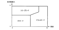
- the first setting unit 1B selects a traveling mode by applying the current vehicle speed and the required driving force to the map shown in FIG. 2, for example, and sets the traveling mode.
- the 1st setting part 1B of this embodiment changes each area
- the first setting unit 1B changing the area of the map, a plurality of maps in which different areas are set for each charging rate of the battery 9 are stored and a map corresponding to the charging rate is selected. Good.
- the second setting unit 1C (setting unit) sets the operation mode based on the input to the selection unit 33.
- the "input” here means an input signal transmitted from the switch to the second setting unit 1C when the driver operates the switch when the selection unit 33 is a switch.
- it means an input signal transmitted from this function to the second setting unit 1C. That is, the second setting unit 1C sets the driving mode of the vehicle 10 to the one selected by the driver or the vehicle 10.
- the normal mode is automatically set when the main power supply of the vehicle 10 is turned on.
- the storage unit 1D stores the relationship between the operating states of the motor 3 and the generator 4 in each operation mode.
- the "operating state” here is the control content to be implemented in the acceleration control, and specifically the content of when and how to control the motor 3 and the generator 4.
- the storage unit 1D of the present embodiment stores a map that determines the operating state based on the accelerator opening and the accelerator opening speed for each operation mode.
- the accelerator opening speed is the accelerator pedal depression speed, and corresponds to a value obtained by differentiating the accelerator opening detected by the accelerator opening sensor 31.
- FIGS. 3(a) to 3(c) An example of a map stored in the storage unit 1D is shown in FIGS. 3(a) to 3(c).
- FIG. 3A is a map in the eco mode
- FIG. 3B is a map in the normal mode
- FIG. 3C is a map in the sports mode.
- the horizontal axis of each map is the accelerator opening degree
- the vertical axis is the accelerator opening speed
- at least three control regions are set in each map.
- connecting operation an operating state during the connecting operation of the motor clutch 8
- an operating state after the completion of the connection of the motor clutch 8 hereinafter, simply referred to as “after the connection completion”.
- three control areas are set in the maps of FIGS. 3A to 3C, four or more control areas may be set.
- the first control region which is indicated as "region 1" in the figure, an operating state in which the motor 3 is put into an unloaded state during the connecting operation to power the generator 4 and a state in which the generator 4 is transitioned to the unloaded state after the connection is completed.
- An operating state in which the motor 3 is switched to the power running state is set. That is, in the first control region, the delay in response is avoided by transmitting the driving force of the generator 4 to the drive shaft 6 until the connection of the motor clutch 8 is completed, and after the connection of the motor clutch 8 is completed.
- the generator 4 is made to stand by as a generator while efficiently securing the assisting force.
- an operating state in which both the motor 3 and the generator 4 are in a no-load state during the connecting operation, and a motor among the motor 3 and the generator 4 after the connection is completed. 3 is set to the powering state.
- the electric power consumption is improved by keeping the two rotary electric machines 3 and 4 in a no-load state until the connection of the motor clutch 8 is completed, and after the connection of the motor clutch 8 is completed, By driving only the motor 3, it is possible to achieve an eco-friendly driving while efficiently securing the assisting force.
- an operating state in which the motor 3 is put into a no-load state during the connecting operation to power the generator 4 and an operating state in which the motor 3 is also powered after the connection is completed. And are set. That is, in the third control area, the response delay is avoided by transmitting the driving force of the generator 4 to the drive shaft 6 until the connection of the motor clutch 8 is completed, as in the first control area. After the connection is completed, not only the generator 4 but also the motor 3 is made to power, so that a stronger sense of acceleration is realized.
- the second control area is the widest among the three control areas. That is, when the operating mode being set is the eco mode, the above-mentioned operating state set in the second control region is most likely to be implemented.
- the first control area is the widest among the three control areas. That is, when the operating mode being set is the normal mode, the above-mentioned operating state set in the first control region is most likely to be implemented.
- the third control area is the widest of the three control areas. That is, when the driving mode being set is the sports mode, the operating state set in the third control area is most likely to be implemented.
- the control unit 1E executes the above-mentioned control during acceleration. That is, when the control unit 1E connects the motor clutch 8 in the disengaged state while the engine 2 is being driven and is being accelerated, the motor 3 is set to the operating state stored in the storage unit 1D and corresponding to the operating mode being set. And control the generator 4.
- control unit 1E will be described with reference to FIGS. 4 to 7.
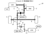
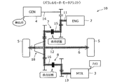
- the thick arrows with patterns in FIGS. 4 to 7 indicate how power is transmitted. Further, in the state shown in FIG. 4, since the engine clutch 7 is connected, the vehicle 10 is traveling only by the driving force of the engine 2.
- the control unit 1E determines whether or not motor assist is required and during acceleration. It is determined whether or not.
- the control unit 1E of the present embodiment performs the former determination based on the required driving force calculated by the calculation unit 1A, and the latter determination based on the accelerator opening and the vehicle speed. If the motor assist is required during acceleration, the above acceleration control is performed, and if the motor assist is not required or is not during acceleration, the acceleration control is not performed.
- the control unit 1E of the present embodiment compares the required driving force with the maximum driving force of the engine 2 and determines that "motor assist is required” if the former is greater than the latter, and "motor assists” if the former is less than the latter. No assistance is required.”
- the situation in which the required driving force becomes larger than the maximum driving force of the engine 2 is, for example, when the driver depresses the accelerator pedal for acceleration. That is, the situation in which motor assistance is required is often during acceleration.
- the maximum driving force of the engine 2 is preset in the control device 1 as a variable value that changes depending on the vehicle speed, for example.
- the control unit 1E acquires the vehicle speed at the time of determining whether or not the motor assist is necessary, and uses a value (maximum driving force) corresponding to the vehicle speed for the determination.
- the control unit 1E selects the map of the operating mode that is being set, and applies the accelerator opening degree and the accelerator opening speed obtained by differentiating the map to the selected map.
- One of the three control areas is extracted and the operating state set in the control area is acquired.
- the control unit 1E selects the map of the normal mode illustrated in FIG. 3B, and operates when the accelerator opening and the accelerator opening speed are applied to this map. If the point is the point A shown in FIG. 3B, the operating state set in the region 1 (first control region) is acquired.
- the control unit 1E causes the generator 4 to perform a power running operation while connecting the disengaged motor clutch 8 to transmit the driving force of the generator 4 to the drive shaft 6, as shown in FIG.
- the driving force until the connection of the motor clutch 8 is completed is supplemented by the generator 4.
- the motor 3 at this time is in a no-load state.
- the driving force of the generator 4 and the driving force of the motor 3 can be temporarily transmitted to the drive shaft 6.
- the control unit 1E switches the motor 3 to the power running state while causing the generator 4 to transition to no load. Therefore, as shown in FIG. 6, both the driving force of the generator 4 and the driving force of the motor 3 are temporarily transmitted to the drive shaft 6, and thereafter, as shown in FIG. 7, the generator 4 is completely unloaded. Then, only the driving force of the motor 3 is transmitted to the drive shaft 6.
- the operating mode being set is the normal mode
- the operating point when the accelerator opening degree and the accelerator opening speed are applied to the map of the normal mode illustrated in FIG. 3B is the region 2 (second control region).
- the control unit 1E connects the motor clutch 8 while leaving the motor 3 and the generator 4 in the unloaded state. Then, when the connection of the motor clutch 8 is completed, the motor 3 is switched to the power running state as shown in FIG. 7.
- the operating mode being set is the normal mode
- the operating point when the accelerator opening and the accelerator opening speed are applied to the map of the normal mode illustrated in FIG. 3B is the region 3 (third control region).
- the operating state set in the third control area is acquired.
- the control unit 1E causes the generator 4 to perform the power running operation while the disengaged motor clutch 8 is connected, and transmits the driving force of the generator 4 to the drive shaft 6.
- the motor 3 at this time is in a no-load state.
- the motor 3 is also switched to the power running state so that the driving forces of both the motor 3 and the generator 4 are transmitted to the drive shaft 6.
- control unit 1E acquires the operating state to be executed at the time of acceleration from the map even when the driving mode being set is the eco mode or the sports mode, and the operating state is set to the operating state. Then, the motor 3 and the generator 4 are controlled.
- FIG. 8 is an example of a flowchart for explaining the control content performed by the control device 1 described above. This flowchart is executed at a predetermined calculation cycle while the main power source of the vehicle 10 is turned on. It should be noted that the setting of the traveling mode by the first setting unit 1B and the setting of the operating mode by the second setting unit 1C of the control device 1 are executed separately from this flowchart, and the setting of the set traveling mode and operating mode is performed. It is assumed that each information is transmitted to the control unit 1E.
- step S1 the information detected by the sensors 31 and 32, the travel mode setting information in the first setting unit 1B, and the operation mode setting information in the second setting unit 1C are transmitted.
- step S2 it is determined whether or not the traveling mode being set is the parallel mode. When the current traveling mode is not the parallel mode, this flowchart is returned. If the current traveling mode is the parallel mode, the process proceeds to step S3, the required driving force is calculated, and it is determined in step S4 whether the motor clutch 8 is in the disengaged state.
- step S5 it is determined whether the required driving force calculated in step S3 is larger than the maximum driving force of the engine 2. If this condition is not satisfied, this flowchart is returned. On the other hand, if the condition of step S5 is satisfied, the process proceeds to step S6, and the operating state corresponding to the operating mode being set is acquired from the correspondence relationship (map in this embodiment) stored in the storage unit 1D.
- step S7 the connection of the motor clutch 8 is started, and the control of the motor 3 and the generator 4 during the connecting operation is performed based on the operating state acquired in step S6 (step S8). Then, it is determined whether or not the connection of the motor clutch 8 is completed (step S9), and the control during the connecting operation is continued until the connection is completed (step S8).
- step S10 the control of the motor 3 and the generator 4 after the completion of the connection is executed based on the operation state acquired in step S6, and the process returns from this flowchart.
- the required driving force is calculated in the next calculation cycle (step S3), and since the motor clutch 8 is in the engaged state, the process proceeds from step S4 to step S11.
- step S11 it is determined whether or not the required driving force calculated in step S3 is larger than the maximum driving force of the engine 2. If this condition is satisfied, the process returns from this flowchart and the connected state of the motor clutch 8 is maintained. On the other hand, if the condition of step S11 is not satisfied, the process proceeds to step S12, the motor clutch 8 is disengaged, the motor 3 and the generator 4 are both controlled to be in the no-load state (step S13), and the process returns to this flowchart.
- both of the two rotary electric machines 3 and 4 are in the no-load state, so that the power consumption can be improved. Therefore, when the disengaged motor clutch 8 is engaged, control can be performed according to the operation mode.
- the storage unit 1D described above stores a map for determining the operating state based on the accelerator opening and the accelerator opening speed for each operation mode.
- the degree of acceleration demand of the occupant can be determined from the accelerator opening degree and the accelerator opening speed, so that control can be performed according to the operation mode.
- control areas are set in the map, and an operating state during connection operation of the motor clutch 8 and an operating state after completion of connection of the motor clutch 8 are set in each control area. ing. For this reason, control according to the operation mode can be performed during the connection operation of the motor clutch 8 and after the completion of the connection.
- the operation mode described above includes the normal mode, and the map of the normal mode has the largest first control region, when the normal mode is selected, the first control region is set.
- the operating conditions provided are the easiest to implement. That is, in the normal mode, the response delay can be eliminated by powering the generator 4 during the connection operation of the motor clutch 8, and the vehicle 10 is driven by the motor 3 after the connection is completed, thereby efficiently securing the assist force.
- the generator 4 can be made to stand by as a generator.
- the assist force can be secured while the response delay is eliminated in the situation where the motor assist is required, so that the control according to the operation mode can be performed.
- the operation mode described above includes the eco mode, and the second control area is the widest in the eco mode map. Therefore, when the eco mode is selected, the second control area is set.
- the operating conditions provided are the easiest to implement. That is, in the eco mode, power consumption can be improved by leaving the rotating electric machines 3 and 4 in a no-load state during the connection operation of the motor clutch 8, and after the connection is completed, the vehicle 3 is driven by the motor 3 to efficiently assist. It is possible to make the generator 4 stand by as a generator while securing power. In this way, in the eco mode, eco-friendly driving with a reduced energy consumption rate can be performed, so that control can be performed according to the driving mode.
- the sports mode is included in the above-mentioned driving modes, and the third control area is the widest in the map of the sports mode. Therefore, when the sports mode is selected, the third control area is set.
- the operating conditions provided are the easiest to implement. That is, in the sports mode, the response delay can be eliminated by powering the generator 4 during the connection operation of the motor clutch 8, and after completion of the connection, a large assist force can be obtained by driving the vehicle 10 with both the rotating electric machines 3 and 4. Can be secured.
- the sports mode it is possible to realize a strong sense of acceleration while eliminating the response delay in a situation where motor assistance is required, and thus it is possible to perform control in accordance with the driving mode.
- the second control area or the third control area may be selected even in the normal mode, for example.
- the widest control area is not always selected in the map of the driving mode being set. That is, according to the control device 1 described above, not only the input to the selection unit 33 but also one of the occupant's operations such as accelerator operation can be taken into consideration, and when the disengaged motor clutch 8 is connected, the operation mode and the occupant Can be controlled according to the intention of
- the content of the above-described acceleration control is an example and is not limited to the above.
- the types of driving modes are not limited to the above-mentioned three (normal mode, eco mode, sports mode), and two of these may be included or other driving modes may be included.
- At least the vehicle 10 may be provided with a plurality of driving modes having different power performances, and one of these may be arbitrarily selected. For example, only one of the switch and the function as the selection unit 33 may be provided.
- Three control areas are set in each of the above three maps, but the type, number, shape, and size of the control areas are not particularly limited.
- two of the first control area and the second control area may be set in the eco mode map, and two of the first control area and the third control area may be set in the sport mode map. ..
- the storage unit 1D only needs to store the relationship between the operating states of the two rotary electric machines 3 and 4 in each operation mode, and need not be stored as the above-described map.
- the operating states of the two rotary electric machines 3 and 4 for each operating mode are uniquely stored, and when the operating mode is the normal mode, the operating state stored in advance can be acquired regardless of the accelerator operation. It may be configured.
- the above-mentioned operation state is an example and is not limited to the above-mentioned contents.
- the above-described control device 1 starts the acceleration control when the required driving force becomes larger than the maximum driving force of the engine 2 during the parallel mode without motor assist and during the acceleration.
- the conditions are not limited to this.
- a determination threshold value set to a value slightly smaller than the maximum driving force of the engine 2 is provided, and during acceleration in parallel mode without motor assist and during acceleration, control during acceleration is performed if the required driving force exceeds this determination threshold value. It may be configured to.
- the determination threshold value may be a preset fixed value or a variable value set according to the traveling state of the vehicle 10 or the like.
- the configuration of the transaxle 20 controlled by the control device 1 described above is an example, and is not limited to the one described above. Further, the relative positions of the engine 2, the motor 3, and the generator 4 with respect to the transaxle 20 are not limited to those described above. The arrangement of the six shafts 11 to 16 in the transaxle 20 may be set according to these relative positions. Further, the arrangement of gears provided on each shaft in the transaxle 20 is also an example, and the arrangement is not limited to the above.
- the above-described acceleration control is a vehicle provided with two rotary electric machines (motors, motor generators, etc.) and an engine, and the power of the engine and the power of the first rotary electric machine are separately supplied from different power transmission paths. It can be applied to a vehicle that transmits power to the drive wheels and also transmits power from the engine to the second rotating electric machine to generate electric power. It suffices that a disconnection mechanism is provided on the transmission path. That is, the acceleration control described above may be applied to a vehicle provided with a transmission other than the transaxle 20 described above.
- the motor clutch 8 (clutch mechanism) is illustrated as the connecting/disconnecting mechanism, but the connecting/disconnecting mechanism is not limited to this.
- a synchro mechanism using an engaging member (sleeve) or a planetary gear mechanism using a sun gear, a carrier and a ring gear may be adopted as the connecting/disconnecting mechanism.
- the engine clutch 7 is not limited to the clutch mechanism and may be a synchronizing mechanism or a planetary gear mechanism.
- the front wheel drive hybrid vehicle in which the engine 2 and the motor 3 are mounted on the front side of the vehicle 10 is illustrated, but the above acceleration control is performed by the rear motor (not shown) on the rear side of the vehicle. It can also be applied to a mounted four-wheel drive hybrid vehicle.
- the rotary electric machines 3 and 4 mounted on the vehicle 10 are not limited to the motor 3 and the generator 4 described above.
- the first rotating electric machine may have a rotating armature or a magnetic field, and may be a motor generator or an electric motor having at least an electric function.
- the second rotating electric machine may be a motor generator or a generator having a rotating armature or a magnetic field and at least a power generation function.
- Control device 1A Calculation part 1B 1st setting part 1C 2nd setting part (setting part) 1D storage unit 1E control unit 2 engine 3 motor (first rotary electric machine) 4 Generator (second rotary electric machine) 5 Drive Wheel 6 Drive Shaft 7 Engine Clutch 8 Motor Clutch (Disengagement Mechanism) 9 Battery 10 Vehicle 20 Transaxle 33 Selector 41 First Path (Power Transmission Path) 42 Second path (power transmission path) 43 Third route
Landscapes
- Engineering & Computer Science (AREA)
- Transportation (AREA)
- Mechanical Engineering (AREA)
- Chemical & Material Sciences (AREA)
- Combustion & Propulsion (AREA)
- Automation & Control Theory (AREA)
- Power Engineering (AREA)
- Hybrid Electric Vehicles (AREA)
- Electric Propulsion And Braking For Vehicles (AREA)
Abstract
車両(10)には、エンジン(2)と第一の回転電機(3)と第二の回転電機(4)とが搭載されており、エンジン(2)の動力及び第一の回転電機(3)の動力が互いに異なる動力伝達経路(41,42)から個別に駆動輪(5)に伝達されるとともにエンジン(2)の動力が第二の回転電機(4)にも伝達されて発電に利用される。車両(10)には、動力伝達経路(42)上に介装された断接機構(8)と、複数の運転モードのうちの一つが選択される選択部(33)とが設けられる。車両(10)の制御装置(1)は、運転モードを設定する設定部(1C)と、各運転モードにおける二つの回転電機(3,4)の作動状態の関係が記憶された記憶部(1D)と、エンジン(2)の駆動中かつ加速時に切断状態の断接機構を接続させる際に、記憶部(1D)に記憶された、設定中の運転モードに対応する作動状態となるよう回転電機(3,4)を制御する制御部(1E)とを備える。
Description
本発明は、駆動源としてのエンジン及び第一の回転電機と、エンジンの動力で発電する第二の回転電機とが装備された車両の制御装置に関する。
従来、エンジンと回転電機(モータ,ジェネレータ,モータジェネレータ)とを装備したハイブリッド車両において、走行モードを切り替えながら走行する車両が実用化されている。走行モードには、バッテリの充電電力を用いてモータのみで走行するEVモード、エンジンによってジェネレータを発電させつつモータのみで走行するシリーズモード、エンジン主体で走行しつつ必要があればモータでアシストするパラレルモード等が含まれる。
エンジンの動力とモータの動力とを個別に出力可能なハイブリッド車両では、エンジンから駆動輪までの動力伝達経路とモータから駆動輪までの動力伝達経路とが別々に設けられる。また、こうしたハイブリッド車両では一般的に、高車速ではエンジン主体で走行するモード(パラレルモード)が選択される。パラレルモードにおいて、モータアシストが不要な場合、すなわちエンジンの動力のみで走行可能な場合には、モータが駆動輪に連れ回されて回転する。このときのモータの連れ回りによって生じた誘起電圧が駆動用バッテリの電圧を上回ると、車両に対して回生ブレーキが働くことになるため、運転者に違和感を与えかねない。
従来は、このような違和感を与えないように、弱め磁束制御を実施することで高速走行時に意図しない回生ブレーキが生じることを防いでいた。しかし、弱め磁束制御の実施には電力を消費するため、電費向上の観点からはこの制御の実施は好ましくない。このような課題に対し、エンジン走行中にモータアシストが不要であれば、モータを動力伝達経路から切り離すクラッチ(断接機構)を設けることが提案されている(例えば特許文献1参照)。
しかしながら、上記のクラッチを備えた車両では、切断状態のクラッチの接続を開始しても、すぐには接続が完了しないことから、モータの動力が駆動輪に伝達されるようになるまでに時間がかかるという課題がある。つまり、モータアシストが必要な状況においてレスポンス遅れが生じることがある。
ところで、車両には、上記の走行モードとは別に、動力性能の異なる複数のモード(以下「運転モード」という)が設けられることがある。運転モードには、例えば、燃費,電費(以下「エネルギー消費率」ともいう)を重視したエコな走りを実現するエコモード、加速性を重視したスポーティーな走りを実現するスポーツモード、加速性及びエネルギー消費率の双方を同等に重視するノーマルモード等が含まれる。
運転モードは、運転者の運転傾向などから車両が自動的に選択してもよいし、乗員が任意に選択してもよい。選択された運転モードによっては、上記のレスポンス遅れが生じても、乗員が「反応が遅い」と感じるとは限らない。つまり、選択された運転モードごとに、上記のレスポンス遅れが許容される場合と許容されない場合とがある。例えば、エコモードが選択されている場合には、必ずしもレスポンス遅れを改善しなくてよく、むしろ燃費,電費の向上を図るほうが運転者の意思や運転モードに即している。
本件の制御装置は、このような課題に鑑み案出されたもので、回転電機の駆動力及びエンジンの駆動力のそれぞれで走行可能なハイブリッド車両において、切断状態の断接機構を接続する際に運転モードに即した制御を実施することを目的の一つとする。なお、この目的に限らず、後述する発明を実施するための形態に示す各構成により導かれる作用効果であって、従来の技術によっては得られない作用効果を奏することも本件の他の目的である。
(1)ここで開示する制御装置は、エンジンと第一の回転電機と第二の回転電機とが搭載され、前記エンジンの動力及び前記第一の回転電機の動力を互いに異なる動力伝達経路から個別に駆動輪に伝達するとともに前記エンジンの動力を前記第二の回転電機にも伝達して発電する車両に設けられる。前記車両には、前記第一の回転電機の動力を前記駆動輪に伝達する動力伝達経路上に介装された断接機構と、動力性能の異なる複数の運転モードのうちの一つが選択される選択部と、が設けられる。また、前記制御装置は、前記選択部に対する入力に基づき前記運転モードを設定する設定部と、各々の前記運転モードにおける前記第一の回転電機と前記第二の回転電機との作動状態の関係が記憶された記憶部と、前記エンジンの駆動中かつ前記車両の加速時に切断状態の前記断接機構を接続させる際に、前記記憶部に記憶された、設定中の前記運転モードに対応する前記作動状態となるように前記第一の回転電機及び前記第二の回転電機を制御する制御部と、を備えている。
なお、前記第一の回転電機とは、回転する電機子又は界磁を有し、少なくとも電動機能を有する電動発電機(モータジェネレータ)又は電動機を意味する。また、前記第二の回転電機とは、回転する電機子又は界磁を有し、少なくとも発電機能を有する電動発電機(モータジェネレータ)又は発電機を意味する。また、前記断接機構としては、例えば、多板クラッチやドグクラッチといったクラッチ機構,係合部材(スリーブ)を用いたシンクロ機構,サンギヤとキャリアとリングギヤとを用いた遊星歯車機構が挙げられる。
(2)前記記憶部には、前記運転モードごとに、アクセル開度及びアクセル開速度に基づいて前記作動状態を決定するマップが記憶されていることが好ましい。
(3)前記マップには、前記第一の回転電機と前記第二の回転電機との作動状態を決定するための少なくとも三つの制御領域が設定されており、各々の前記制御領域には、前記断接機構の接続動作中の前記作動状態と前記断接機構の接続完了後の前記作動状態とが設定されていることが好ましい。
(3)前記マップには、前記第一の回転電機と前記第二の回転電機との作動状態を決定するための少なくとも三つの制御領域が設定されており、各々の前記制御領域には、前記断接機構の接続動作中の前記作動状態と前記断接機構の接続完了後の前記作動状態とが設定されていることが好ましい。
(4)前記運転モードには、ノーマルモードが含まれることが好ましい。この場合、前記ノーマルモードの前記マップでは、前記少なくとも三つの制御領域のうち、前記接続動作中に前記第一の回転電機を無負荷状態とし前記第二の回転電機を力行させる前記作動状態と、前記接続完了後に前記第二の回転電機を無負荷に遷移させつつ前記第一の回転電機を力行状態に切り替える前記作動状態とが設定された第一制御領域が最も広いことが好ましい。
(5)前記運転モードには、加速性よりもエネルギー消費率を重視するエコモードが含まれることが好ましい。この場合、前記エコモードの前記マップでは、前記少なくとも三つの制御領域のうち、前記接続動作中に前記第一の回転電機及び前記第二の回転電機をいずれも無負荷状態とする前記作動状態と、前記接続完了後に前記第一の回転電機及び前記第二の回転電機のうち前記第一の回転電機を力行状態に切り替える前記作動状態とが設定された第二制御領域が最も広いことが好ましい。
(6)前記運転モードには、エネルギー消費率よりも加速性を重視するスポーツモードが含まれることが好ましい。この場合、前記スポーツモードの前記マップでは、前記少なくとも三つの制御領域のうち、前記接続動作中に前記第一の回転電機を無負荷状態とし前記第二の回転電機を力行させる前記作動状態と、前記接続完了後に前記第一の回転電機も併せて力行させる前記作動状態とが設定された第三制御領域が最も広いことが好ましい。
開示の車両の制御装置によれば、設定中の運転モードに対応して二つの回転電機を制御することで、レスポンス遅れを許容できない場面ではレスポンス遅れを適切に改善でき、レスポンス遅れを許容できる場面では電費向上を図ることができる。これにより、切断状態の断接機構を接続する際に運転モードに即した制御を実施することができる。
図面を参照して、実施形態としての車両の制御装置について説明する。以下に示す実施形態はあくまでも例示に過ぎず、以下の実施形態で明示しない種々の変形や技術の適用を排除する意図はない。本実施形態の各構成は、それらの趣旨を逸脱しない範囲で種々変形して実施することができる。また、必要に応じて取捨選択することができ、あるいは適宜組み合わせることができる。
[1.全体構成]
本実施形態の制御装置1は、図1に示す車両10に適用され、この車両10に搭載されるエンジン2,モータ3,ジェネレータ4,クラッチ7,8等を制御する。この車両10は、駆動源としてのエンジン2と走行用のモータ3(第一の回転電機)と発電用のジェネレータ4(第二の回転電機)とを装備したハイブリッド車両である。なお、本実施形態では、これらの機器2,3,4が車両10の前側に搭載されているものとする。
本実施形態の制御装置1は、図1に示す車両10に適用され、この車両10に搭載されるエンジン2,モータ3,ジェネレータ4,クラッチ7,8等を制御する。この車両10は、駆動源としてのエンジン2と走行用のモータ3(第一の回転電機)と発電用のジェネレータ4(第二の回転電機)とを装備したハイブリッド車両である。なお、本実施形態では、これらの機器2,3,4が車両10の前側に搭載されているものとする。
ジェネレータ4はエンジン2に連結され、モータ3の作動状態とは独立して作動可能である。車両10にはEVモード,シリーズモード,パラレルモードの三種類の走行モードが用意される。これらの走行モードは、制御装置1によって、車両状態や走行状態,運転者の要求駆動力等に応じて択一的に選択され、その種類に応じてエンジン2,モータ3,ジェネレータ4が使い分けられる。
図2は、車速及び要求駆動力に応じて走行モードを選択するときに用いられるマップの一例である。EVモードは、エンジン2及びジェネレータ4を停止させたまま、駆動用のバッテリ9(図1参照)の充電電力を用いてモータ3のみで車両10を駆動する走行モードである。EVモードは、要求駆動力及び車速がいずれも低い場合やバッテリ9の充電レベルが高い場合に選択される。シリーズモードは、エンジン2でジェネレータ4を駆動して発電しつつ、その電力を利用してモータ3で車両10を駆動する走行モードである。シリーズモードは、要求駆動力が高い場合やバッテリ9の充電レベルが低い場合に選択される。パラレルモードは、おもにエンジン2の駆動力で車両10を駆動し、必要に応じてモータ3で車両10の駆動をアシストする走行モードであり、車速が高い場合や要求駆動力が高い場合に選択される。
車両10には、上記の走行モードとは別に、動力性能の異なる複数の運転モードが用意される。本実施形態の運転モードには、エコモード,スポーツモード,ノーマルモードの三種類が含まれる。エコモードは、加速性よりも燃費,電費(以下「エネルギー消費率」という)を重視したエコな走りを実現する運転モードであり、反対に、スポーツモードは、エネルギー消費率よりも加速性を重視したスポーティーな走りを実現する運転モードである。また、ノーマルモードは、加速性及びエネルギー消費率の双方を同等に重視する運転モードであり、車両10の主電源がオフからオンになったときに自動的に設定される初期モードでもある。運転モードは、運転者の運転傾向などから車両10が自動的に選択してもよいし、乗員が任意に選択してもよい。運転モードの種類に応じて、制御装置1により、アクセルペダルの踏み込み操作に対する車軸出力が変えられる。
図1に示すように、駆動輪5(ここでは前輪)には、複数のギヤやクラッチを内蔵したトランスアクスル20を介してエンジン2及びモータ3が並列に接続され、エンジン2及びモータ3のそれぞれの動力が互いに異なる動力伝達経路から個別に伝達される。すなわち、エンジン2及びモータ3のそれぞれは、車両10の駆動軸6を駆動する。また、エンジン2には、トランスアクスル20を介してジェネレータ4及び駆動輪5が並列に接続され、エンジン2の動力が、駆動輪5に加えてジェネレータ4にも伝達される。
トランスアクスル20は、デファレンシャルギヤ18(差動装置、以下「デフ18」と呼ぶ)を含むファイナルドライブ(終減速機)とトランスミッション(減速機)とを一体に形成した動力伝達装置であり、駆動源と被駆動装置との間の動力伝達を担う複数の機構を内蔵する。
エンジン2は、ガソリンや軽油を燃料とする内燃機関(ガソリンエンジン,ディーゼルエンジン)である。このエンジン2は、クランクシャフト2aの向きが車両10の車幅方向に一致するように横向きに配置されたいわゆる横置きエンジンであり、トランスアクスル20の右側面に対して固定される。クランクシャフト2aは、駆動軸6に対して平行に配置される。エンジン2の作動状態は、制御装置1で制御されてもよいし、制御装置1とは別の電子制御装置(図示略)で制御されてもよい。
本実施形態のモータ3及びジェネレータ4はいずれも、電動機としての機能と発電機としての機能とを兼ね備えた電動発電機(モータ・ジェネレータ)である。モータ3は、バッテリ9と電力の授受を行なう駆動源であり、おもに電動機として機能して車両10を駆動し、回生時には発電機として機能する。
ジェネレータ4は、エンジン2を始動させる際に電動機(スターター)として機能し、エンジン2の作動時にはエンジン動力で駆動されて発電する。さらにジェネレータ4は、力行状態では車両10の駆動軸6に駆動力を伝達する。モータ3及びジェネレータ4の各周囲(又は各内部)には、直流電流と交流電流とを変換するインバータ(図示略)が設けられる。モータ3及びジェネレータ4の各回転速度及び各作動状態(力行運転,回生・発電運転)は、インバータを制御することで制御される。
車両10には、車両10に搭載される各種装置を統合制御する制御装置1が設けられる。また、車両10には、アクセルペダルの踏み込み操作量(アクセル開度)を検出するアクセル開度センサ31と、車速を検出する車速センサ32とが設けられる。また、車両10には、複数の運転モードのうちの一つが選択される選択部33が設けられる。選択部としては、例えば、運転者が任意に運転モードを選択するために操作するスイッチや、車両10が運転者の運転傾向を認識,学習し、自動で運転モードを選択する機能が挙げられる。なお、選択部33としてのスイッチは、運転者が運転中に操作可能な位置に配置され、選択部33としての機能は、例えば制御装置1で実行されるプログラムの一部の機能として設けられていてもよいし、制御装置1とは別の電子制御装置内に設けられてもよい。アクセル開度センサ31,車速センサ32で検出された情報及び選択部33に対する入力は、制御装置1に伝達される。
制御装置1は、例えばマイクロプロセッサやROM,RAM等を集積したLSIデバイスや組み込み電子デバイスとして構成された電子制御装置であり、車両10に搭載される各種装置を統合制御する。本実施形態の制御装置1は、運転者の要求駆動力等に応じて走行モードを選択し、選択した走行モードに応じて各種機器(例えばエンジン2や回転電機3,4)を制御するとともにトランスアクスル20内のクラッチ7,8の断接状態を制御する。また、制御装置1は、選択された運転モードを設定し、その運転モードに応じて、アクセルペダルの踏み込み操作に対する車軸出力を変更する。
本実施形態のトランスアクスル20には、互いに平行に配列された六つの軸11~16が設けられる。以下、クランクシャフト2aと同軸上に接続される回転軸を入力軸11と呼び、駆動軸6と同軸上に接続される回転軸を出力軸12と呼ぶ。また、モータ3の回転軸,ジェネレータ4の回転軸のそれぞれと同軸上に接続される回転軸を、モータ軸13,ジェネレータ軸14と呼ぶ。また、モータ軸13と出力軸12との間の動力伝達経路上に配置された回転軸を第一カウンタ軸15と呼び、入力軸11と出力軸12との間の動力伝達経路上に配置された回転軸を第二カウンタ軸16と呼ぶ。六つの軸11~16はいずれも、両端部が軸受(図示略)を介してトランスアクスル20のケーシングに軸支される。
トランスアクスル1の内部には、図1中に模様付き太矢印で示す三つの動力伝達経路が形成される。具体的には、エンジン2から入力軸11及び第一カウンタ軸15を介して出力軸12に至る動力伝達経路(以下「第一経路41」と呼ぶ)と、モータ3からモータ軸13及び第二カウンタ軸16を介して出力軸12に至る動力伝達経路(以下「第二経路42」と呼ぶ)と、エンジン2から入力軸11を介してジェネレータ軸14に至る動力伝達経路(以下「第三経路43」と呼ぶ)とが形成される。第一経路41及び第二経路42は駆動用の動力伝達経路であり、第三経路43は発電用の動力伝達経路である。
第一経路41上には、ジェネレータ4と同期して回転することで動力が伝達される入力軸11及び入力軸11の動力が伝達される第一カウンタ軸15が設けられる。また、第一経路41の中途(本実施形態では第一カウンタ軸15上)には、その動力伝達を断接するクラッチ7が介装される。以下、このクラッチ7を「エンジンクラッチ7」とも呼ぶ。第一カウンタ軸15には、右側(エンジン2に近い側)から順に、入力軸11のギヤ11aと噛み合うギヤ15aと、エンジンクラッチ7と、出力軸12に設けられたデフ18のリングギヤ18bと噛み合うギヤ15bとが設けられる。
エンジンクラッチ7は、例えば湿式の多板クラッチやドグクラッチである。エンジンクラッチ7よりも動力伝達経路の上流側(エンジン2及びジェネレータ4側)の動力は、エンジンクラッチ7が係合状態であれば出力軸12に伝達され、切断(開放)状態であれば遮断される。なお、エンジンクラッチ7の断接状態は、制御装置1によって制御される。
第二経路42は、モータ3の駆動力を駆動輪5に伝達する動力伝達経路である。第二経路42上には、モータ3と同期して回転することで動力が伝達されるモータ軸13と、モータ軸13の動力が伝達される第二カウンタ軸16とが設けられる。また、第二経路42の中途(本実施形態では第二カウンタ軸16上)には、その動力伝達を断接するクラッチ8(断接機構)が介装される。以下、このクラッチ8を「モータクラッチ8」と呼ぶ。第二カウンタ軸16には、右側から順に、モータ軸13のギヤ13aと噛み合うギヤ16aと、モータクラッチ8と、デフ18のリングギヤ18bと噛み合うギヤ16bとが設けられる。
モータクラッチ8は、例えば湿式の多板クラッチやドグクラッチである。モータクラッチ8よりも動力伝達経路の上流側の動力(すなわちモータ3の駆動力)は、モータクラッチ8が係合状態であれば出力軸12に伝達され、切断(開放)状態であれば遮断される。なお、モータクラッチ8の断接状態は、制御装置1によって制御される。
第三経路43は、エンジン2からジェネレータ4への動力伝達及びジェネレータ4からエンジン2への動力伝達に係る経路であり、ジェネレータ4が電動機及び発電機のそれぞれとして作動した場合の動力伝達を担うものである。ジェネレータ4が電動機として作動する場合には、ジェネレータ4の駆動力により入力軸11を回転させることができる。エンジン2及びジェネレータ4は、クラッチを介すことなく、互いに噛み合うギヤ11a,14aを介して直結されている。なお、ジェネレータ4が電動機として作動する場合には、ジェネレータ4の駆動力は第三経路43の一部と第一経路41の一部とを介して駆動輪5に伝達される。
本実施形態では、走行モードがEVモード又はシリーズモードである場合には、エンジンクラッチ7が切断状態とされ、モータクラッチ8が係合状態とされる。また、走行モードがパラレルモードであってモータアシスト(モータ3の駆動力)が不要な場合には、エンジンクラッチ7が係合状態とされ、モータクラッチ8が切断状態とされる。また、走行モードがパラレルモードであってモータアシストが必要な場合には、エンジンクラッチ7及びモータクラッチ8の双方が係合状態とされる。
[2.制御構成]
本実施形態の制御装置1は、エンジン2の駆動力のみでの走行中かつ加速時にモータアシストが必要な場合、そのとき設定中の運転モードに基づいて、モータクラッチ8を接続させる際のモータ3及びジェネレータ4を制御する。以下、この制御を「加速時制御」と呼ぶ。加速時制御は、エンジン2の動力で駆動輪5を駆動している際(エンジン2の駆動中)にアクセルペダルが踏み込まれ、車両10に対する要求駆動力の増加に伴いモータクラッチ8を「切断状態」から「係合状態」に変更するときに実施される制御である。つまり、加速時制御は、走行モードがパラレルモードに設定されており、かつ、モータアシストがない加速時に行われる。
本実施形態の制御装置1は、エンジン2の駆動力のみでの走行中かつ加速時にモータアシストが必要な場合、そのとき設定中の運転モードに基づいて、モータクラッチ8を接続させる際のモータ3及びジェネレータ4を制御する。以下、この制御を「加速時制御」と呼ぶ。加速時制御は、エンジン2の動力で駆動輪5を駆動している際(エンジン2の駆動中)にアクセルペダルが踏み込まれ、車両10に対する要求駆動力の増加に伴いモータクラッチ8を「切断状態」から「係合状態」に変更するときに実施される制御である。つまり、加速時制御は、走行モードがパラレルモードに設定されており、かつ、モータアシストがない加速時に行われる。
本実施形態の車両10には、運転モードとして、上述したエコモード,スポーツモード,ノーマルモードの三種類が用意されている。運転モードは、乗員によって選択される場合と車両10が自動的に選択する場合がある。いずれの場合であっても、加速時制御では、設定中の運転モードを参照することで運転モード(どのような走りを実現すべきか)を把握し、その運転モードに即した制御の実現を図る。例えば、運転モードが乗員によって選択される場合には、乗員の意思に即した制御が実現される。
本実施形態の制御装置1には、要求駆動力を算出する算出部1Aと、走行モードを設定する第一設定部1Bと、運転モードを設定する第二設定部1Cと、加速時制御を実施するための記憶部1D及び制御部1Eとが設けられる。これらの要素は、制御装置1で実行されるプログラムの一部の機能を示すものであり、ソフトウェアで実現されるものとする。ただし、各機能の一部又は全部をハードウェア(電子回路)で実現してもよく、あるいはソフトウェアとハードウェアとを併用して実現してもよい。
算出部1Aは、例えばアクセル開度センサ31で検出されたアクセル開度(APS)と車速センサ32で検出された車速とに基づいて、車両10に対する要求駆動力(要求出力)を算出する。なお、算出部1Aは、前後加速度や横加速度,ステアリング角度や車体の傾きといったパラメータを考慮して、より正確な要求駆動力を算出してもよい。算出部1Aは、加速時制御を実施する場合に限らず、例えば車両10の主電源が投入されている状態や車速が0でない状態で常に要求駆動力を算出する。
第一設定部1Bは、例えば図2に示すマップに対し、現在の車速及び要求駆動力を適用することで走行モードを選択し、その走行モードを設定する。本実施形態の第一設定部1Bは、バッテリ9の充電状態(充電率)に応じて、図2に例示したマップの各領域を変更する。例えば、バッテリ9の充電率が低くなるにつれ、EVモードよりもシリーズモードが選択されやすくなるよう、マップの領域が変更される。なお、第一設定部1Bがマップの領域を変更する代わりに、バッテリ9の充電率ごとに異なる領域が設定されたマップを複数記憶しておき、充電率に対応するマップを選択する構成としてもよい。
第二設定部1C(設定部)は、選択部33に対する入力に基づいて運転モードを設定する。ここでいう「入力」とは、選択部33がスイッチである場合には運転者がスイッチ操作したときにスイッチから第二設定部1Cに伝達される入力信号を意味し、選択部33が電子制御装置の機能である場合には、この機能から第二設定部1Cに伝達される入力信号を意味する。すなわち、第二設定部1Cは、車両10の運転モードを、運転者又は車両10によって選択されたものに設定する。なお、本実施形態の制御装置1では、車両10の主電源がオフからオンになった時点では、自動的にノーマルモードが設定されるものとする。
記憶部1Dは、各運転モードにおけるモータ3とジェネレータ4との作動状態との関係を記憶している。ここでいう「作動状態」とは、加速時制御で実施する制御内容であり、具体的にはモータ3及びジェネレータ4をいつどのように制御するのかという内容である。本実施形態の記憶部1Dには、運転モードごとに、アクセル開度及びアクセル開速度に基づいて作動状態を決定するマップが記憶されている。なお、アクセル開速度は、アクセルペダルの踏み込み速度であり、アクセル開度センサ31で検出されたアクセル開度を微分した値に相当する。
記憶部1Dに記憶されるマップの一例を図3(a)~(c)に示す。図3(a)はエコモードのマップであり、図3(b)はノーマルモードのマップであり、図3(c)はスポーツモードのマップである。各マップの横軸はアクセル開度、縦軸はアクセル開速度であり、各マップには少なくとも三つの制御領域が設定されている。各制御領域には、モータクラッチ8の接続動作中(以下、単に「接続動作中」という)の作動状態とモータクラッチ8の接続完了後(以下、単に「接続完了後」という)の作動状態とが設定されている。なお、図3(a)~(c)のマップには三つの制御領域が設定されているが、四つ以上の制御領域が設定されていてもよい。
以下、具体的に説明する。図中「領域1」と表記している第一制御領域には、接続動作中にモータ3を無負荷状態としジェネレータ4を力行させる作動状態と、接続完了後にジェネレータ4を無負荷に遷移させつつモータ3を力行状態に切り替える作動状態とが設定されている。つまり、第一制御領域では、モータクラッチ8の接続が完了するまでの間はジェネレータ4の駆動力を駆動軸6に伝達させることでレスポンス遅れを回避し、モータクラッチ8の接続が完了したのちはアシスト力を発生させる回転電機をジェネレータ4からモータ3へと変更することで、効率良くアシスト力を確保しつつジェネレータ4を発電機として待機させる。
図中「領域2」と表記している第二制御領域には、接続動作中にモータ3及びジェネレータ4をいずれも無負荷状態とする作動状態と、接続完了後にモータ3及びジェネレータ4のうちモータ3を力行状態に切り替える作動状態とが設定されている。つまり、第二制御領域では、モータクラッチ8の接続が完了するまでの間は二つの回転電機3,4を無負荷状態にすることで電費向上を図り、モータクラッチ8の接続が完了したのちはモータ3のみを駆動させることで、効率よくアシスト力を確保しつつエコな走りを実現する。
図中「領域3」と表記している第三制御領域には、接続動作中にモータ3を無負荷状態としジェネレータ4を力行させる作動状態と、接続完了後にモータ3も併せて力行させる作動状態とが設定されている。つまり、第三制御領域では、モータクラッチ8の接続が完了するまでの間は第一制御領域と同様、ジェネレータ4の駆動力を駆動軸6に伝達させることでレスポンス遅れを回避し、モータクラッチ8の接続が完了したのちはジェネレータ4に加えてモータ3も力行させることで、より強い加速感を実現する。
図3(a)に示すように、エコモードのマップでは、三つの制御領域のうち第二制御領域が最も広い。つまり、設定中の運転モードがエコモードである場合には、第二制御領域に設定されている上記の作動状態が最も実施されやすい。図3(b)に示すように、ノーマルモードのマップでは、三つの制御領域のうち第一制御領域が最も広い。つまり、設定中の運転モードがノーマルモードである場合には、第一制御領域に設定されている上記の作動状態が最も実施されやすい。図3(c)に示すように、スポーツモードのマップでは、三つの制御領域のうち第三制御領域が最も広い。つまり、設定中の運転モードがスポーツモードである場合には、第三制御領域に設定されている上記の作動状態が最も実施されやすい。
制御部1Eは、上記の加速時制御を実施するものである。すなわち制御部1Eは、エンジン2の駆動中かつ加速時に切断状態のモータクラッチ8を接続させる際に、記憶部1Dに記憶された、設定中の運転モードに対応する作動状態となるようにモータ3及びジェネレータ4を制御する。
ここで、制御部1Eの構成について、図4~図7を用いて説明する。なお、図4~図7中の模様付き太矢印は、動力の伝わり方を示す。また、図4に示す状態ではエンジンクラッチ7が接続されていることから、エンジン2の駆動力のみで車両10は走行している。
制御部1Eは、図4に示すように、第一設定部1Bによりパラレルモードが設定されており、かつ、モータクラッチ8が切断状態である場合に、モータアシストの要否判定と加速時であるか否かの判定とを実施する。本実施形態の制御部1Eは、算出部1Aで算出される要求駆動力に基づき前者の判定を実施、アクセル開度及び車速に基づき後者の判定を実施する。モータアシストが必要な加速時であれば上記の加速時制御を実施し、モータアシストが不要である場合又は加速時でない場合は加速時制御を実施しない。
本実施形態の制御部1Eは、要求駆動力とエンジン2の最大駆動力とを比較し、前者が後者よりも大きければ「モータアシストが必要」と判定し、前者が後者以下であれば「モータアシストは不要」と判定する。要求駆動力がエンジン2の最大駆動力よりも大きくなる状況としては、例えば運転者が加速のためにアクセルペダルを踏み込んだときが挙げられる。つまり、モータアシストが必要な状況は、加速時となることが多い。なお、エンジン2の最大駆動力は、例えば車速に応じて変化する可変値として制御装置1に予め設定されている。制御部1Eは、モータアシストの要否判定の時点における車速を取得し、この車速に応じた値(最大駆動力)を判定に用いる。
制御部1Eは、加速時制御を実施する場合には、設定中の運転モードのマップを選択し、アクセル開度及びこれを微分して求めたアクセル開速度を、選択したマップに適用することで三つの制御領域の中から一つを抽出し、その制御領域に設定されている作動状態を取得する。例えば、設定中の運転モードがノーマルモードである場合、制御部1Eは図3(b)に例示するノーマルモードのマップを選択し、アクセル開度及びアクセル開速度をこのマップに適用したときの運転点が図3(b)中に示すA点であれば、領域1(第一制御領域)に設定されている作動状態を取得する。
この場合、制御部1Eは、図5に示すように、切断状態のモータクラッチ8を接続させつつジェネレータ4を力行運転させて、ジェネレータ4の駆動力を駆動軸6に伝達させる。これにより、モータクラッチ8の接続が完了するまでの間の駆動力をジェネレータ4によって補填する。なお、このときのモータ3は無負荷状態である。モータクラッチ8の接続が完了した時点では、一時的にジェネレータ4の駆動力もモータ3の駆動力も駆動軸6に伝達可能な状態となる。制御部1Eは、接続が完了するとジェネレータ4を無負荷に遷移させつつモータ3を力行状態に切り替える。このため、図6に示すように、一時的にジェネレータ4の駆動力及びモータ3の駆動力がいずれも駆動軸6に伝達され、その後、図7に示すように、ジェネレータ4が完全に無負荷状態になりモータ3の駆動力のみが駆動軸6に伝達される。
また、設定中の運転モードがノーマルモードであって、図3(b)に例示するノーマルモードのマップにアクセル開度及びアクセル開速度を適用したときの運転点が領域2(第二制御領域)に該当する場合には、第二制御領域に設定されている作動状態を取得する。この場合、制御部1Eは、モータ3及びジェネレータ4をいずれも無負荷状態としたままモータクラッチ8を接続させる。そして、モータクラッチ8の接続が完了したら、図7に示すようにモータ3を力行状態に切り替える。
また、設定中の運転モードがノーマルモードであって、図3(b)に例示するノーマルモードのマップにアクセル開度及びアクセル開速度を適用したときの運転点が領域3(第三制御領域)に該当する場合には、第三制御領域に設定されている作動状態を取得する。この場合、制御部1Eは、図5に示すように、切断状態のモータクラッチ8を接続させつつジェネレータ4を力行運転させて、ジェネレータ4の駆動力を駆動軸6に伝達させる。なお、このときのモータ3は無負荷状態である。モータクラッチ8の接続完了後は、図6に示すように、モータ3も力行状態に切り替えることで、モータ3及びジェネレータ4の両方の駆動力を駆動軸6に伝達させる。
なお、制御部1Eは、設定中の運転モードがエコモード又はスポーツモードである場合にもノーマルモードである場合と同様に、マップから加速時に実施する作動状態を取得し、その作動状態となるようにモータ3及びジェネレータ4を制御する。
[3.フローチャート]
図8は、上述した制御装置1で実施される制御内容を説明するためのフローチャート例である。このフローチャートは、車両10の主電源が投入されている状態で所定の演算周期で実施される。なお、制御装置1の第一設定部1Bによる走行モードの設定と第二設定部1Cによる運転モードの設定とは、このフローチャートとは別に実行されるものとし、設定された走行モード及び運転モードの各情報は制御部1Eに伝達されるものとする。
図8は、上述した制御装置1で実施される制御内容を説明するためのフローチャート例である。このフローチャートは、車両10の主電源が投入されている状態で所定の演算周期で実施される。なお、制御装置1の第一設定部1Bによる走行モードの設定と第二設定部1Cによる運転モードの設定とは、このフローチャートとは別に実行されるものとし、設定された走行モード及び運転モードの各情報は制御部1Eに伝達されるものとする。
ステップS1では、各センサ31,32で検出された情報,第一設定部1Bでの走行モードの設定情報,第二設定部1Cでの運転モードの設定情報が伝達される。ステップS2では、設定中の走行モードがパラレルモードであるか否かが判定される。現在の走行モードがパラレルモードでない場合はこのフローチャートをリターンする。現在の走行モードがパラレルモードである場合はステップS3に進み、要求駆動力が算出され、ステップS4においてモータクラッチ8が切断状態であるか否かが判定される。
モータクラッチ8が切断状態であればステップS5に進み、ステップS3で算出された要求駆動力がエンジン2の最大駆動力よりも大きいか否かが判定される。この条件を満たさなければ、このフローチャートをリターンする。一方、ステップS5の条件を満たす場合はステップS6に進み、設定中の運転モードに対応する作動状態を、記憶部1Dに記憶されている対応関係(本実施形態ではマップ)から取得する。ステップS7では、モータクラッチ8の接続が開始されるとともに、ステップS6で取得した作動状態に基づき接続動作中におけるモータ3及びジェネレータ4の制御が実施される(ステップS8)。そして、モータクラッチ8の接続が完了したか否かが判定され(ステップS9)、接続が完了するまで接続動作中の制御が継続される(ステップS8)。
モータクラッチ8の接続が完了して係合状態となったらステップS10に進み、ステップS6で取得した作動状態に基づき接続完了後におけるモータ3及びジェネレータ4の制御が実施され、このフローチャートをリターンする。この場合、次の演算周期において、要求駆動力が算出され(ステップS3)、モータクラッチ8が係合状態であるためステップS4からステップS11に進む。
ステップS11では、ステップS3で算出された要求駆動力がエンジン2の最大駆動力よりも大きいか否かが判定される。この条件を満たす場合は、このフローチャートをリターンし、モータクラッチ8の接続状態が維持される。一方、ステップS11の条件を満たさない場合は、ステップS12に進み、モータクラッチ8が切断され、モータ3及びジェネレータ4がいずれも無負荷状態に制御されて(ステップS13)、このフローチャートをリターンする。
[4.効果]
(1)上述した制御装置1では、エンジン2の駆動中かつ加速時において、断接機構(本実施形態ではモータクラッチ8)を切断状態から係合状態に移行する際に、記憶部1Dに記憶された、設定中の運転モードに対応する作動状態となるように二つの回転電機3,4が制御される。例えば、モータアシストが必要な状況においてレスポンス遅れを許容できない場面では、第二の回転電機(本実施形態ではジェネレータ4)の駆動力が駆動輪5に伝達されるようジェネレータ4が制御されることで、レスポンス遅れを適切に改善できる。反対に、レスポンス遅れを許容できる場面では二つの回転電機3,4がいずれも無負荷状態とされることで、電費向上を図ることができる。したがって、切断状態のモータクラッチ8を接続する際に運転モードに即した制御を実施できる。
(1)上述した制御装置1では、エンジン2の駆動中かつ加速時において、断接機構(本実施形態ではモータクラッチ8)を切断状態から係合状態に移行する際に、記憶部1Dに記憶された、設定中の運転モードに対応する作動状態となるように二つの回転電機3,4が制御される。例えば、モータアシストが必要な状況においてレスポンス遅れを許容できない場面では、第二の回転電機(本実施形態ではジェネレータ4)の駆動力が駆動輪5に伝達されるようジェネレータ4が制御されることで、レスポンス遅れを適切に改善できる。反対に、レスポンス遅れを許容できる場面では二つの回転電機3,4がいずれも無負荷状態とされることで、電費向上を図ることができる。したがって、切断状態のモータクラッチ8を接続する際に運転モードに即した制御を実施できる。
(2)上述した記憶部1Dには、運転モードごとに、アクセル開度及びアクセル開速度に基づいて作動状態を決定するマップが記憶されている。これにより、上述した制御装置1によれば、アクセル開度とアクセル開速度とから乗員の加速要求度合いを判断できるため、運転モードに即した制御を実施できる。
(3)また、マップには少なくとも三つの制御領域が設定されており、各制御領域にはモータクラッチ8の接続動作中の作動状態と、モータクラッチ8の接続完了後の作動状態とが設定されている。このため、モータクラッチ8の接続動作中及び接続完了後のそれぞれにおいて、運転モードに即した制御を実施できる。
(4)上述した運転モードにはノーマルモードが含まれており、ノーマルモードのマップでは第一制御領域が最も広くなっているため、ノーマルモードが選択されている場合には第一制御領域に設定されている作動状態が最も実施されやすくなっている。すなわち、ノーマルモードでは、モータクラッチ8の接続動作中にジェネレータ4を力行させることでレスポンス遅れを解消でき、接続完了後はモータ3によって車両10を駆動することで、効率良くアシスト力を確保しつつジェネレータ4を発電機として待機させることができる。このように、ノーマルモードでは、モータアシストが必要な状況においてレスポンス遅れを解消しつつアシスト力も確保できるため、運転モードに即した制御を実施できる。
(5)上述した運転モードにはエコモードが含まれており、エコモードのマップでは第二制御領域が最も広くなっているため、エコモードが選択されている場合には第二制御領域に設定されている作動状態が最も実施されやすくなっている。すなわち、エコモードでは、モータクラッチ8の接続動作中に回転電機3,4を無負荷状態とすることで電費を向上でき、接続完了後はモータ3によって車両10を駆動することで、効率良くアシスト力を確保しつつジェネレータ4を発電機として待機させることができる。このように、エコモードでは、エネルギー消費率を抑えたエコな運転ができるため、運転モードに即した制御を実施できる。
(6)上述した運転モードにはスポーツモードが含まれており、スポーツモードのマップでは第三制御領域が最も広くなっているため、スポーツモードが選択されている場合には第三制御領域に設定されている作動状態が最も実施されやすくなっている。すなわち、スポーツモードでは、モータクラッチ8の接続動作中にジェネレータ4を力行させることでレスポンス遅れを解消でき、接続完了後は回転電機3,4の双方によって車両10を駆動することで大きなアシスト力を確保できる。このように、スポーツモードでは、モータアシストが必要な状況においてレスポンス遅れを解消しつつ強い加速感を実現できるため、運転モードに即した制御を実施できる。
(7)なお、上述したマップには、三つの制御領域が設定されており、アクセル操作によっては、例えばノーマルモードであっても第二制御領域又は第三制御領域が選択されることがある。言い換えると、アクセル操作によっては、設定中の運転モードのマップにおいて、必ずしも最も広い制御領域が選択されるとは限らない。つまり、上述した制御装置1によれば、選択部33への入力だけでなく、アクセル操作という乗員の操作の一つをも考慮でき、切断状態のモータクラッチ8を接続する際に運転モード及び乗員の意思に即した制御を実施できる。
[5.その他]
上述した加速時制御の内容は一例であって、上述したものに限られない。例えば、運転モードの種類は上述した三つ(ノーマルモード,エコモード,スポーツモード)に限られず、これらのうちの二つが含まれてもよいし、他の運転モードが含まれてもよい。少なくとも、車両10には、動力性能の異なる複数の運転モードが設けられていればよく、これらのうちの一つが任意に選択されるように構成されていればよい。例えば、選択部33としてのスイッチ及び機能のいずれか一方のみが設けられていてもよい。
上述した加速時制御の内容は一例であって、上述したものに限られない。例えば、運転モードの種類は上述した三つ(ノーマルモード,エコモード,スポーツモード)に限られず、これらのうちの二つが含まれてもよいし、他の運転モードが含まれてもよい。少なくとも、車両10には、動力性能の異なる複数の運転モードが設けられていればよく、これらのうちの一つが任意に選択されるように構成されていればよい。例えば、選択部33としてのスイッチ及び機能のいずれか一方のみが設けられていてもよい。
上述した三つのマップには、それぞれ三つの制御領域が設定されているが、制御領域の種類,個数,形状,大きさは特に限られない。例えば、エコモードのマップに、第一制御領域及び第二制御領域の二つが設定されてもよいし、スポーツモードのマップに、第一制御領域及び第三制御領域の二つが設定されてもよい。なお、記憶部1Dには、各運転モードにおける二つの回転電機3,4の作動状態の関係が記憶されていればよく、上述したようなマップとして記憶されていなくてもよい。例えば、各運転モードに対する二つの回転電機3,4の作動状態が一意に記憶されており、運転モードがノーマルモードである場合には、アクセル操作によらず、予め記憶された作動状態を取得できる構成としてもよい。なお、上述した作動状態は一例であって、上述した内容に限られない。
上述した制御装置1は、モータアシストなしのパラレルモード中かつ加速時に、要求駆動力がエンジン2の最大駆動力よりも大きくなった場合に加速時制御を開始しているが、加速時制御の開始条件はこれに限られない。例えば、エンジン2の最大駆動力よりもやや小さな値に設定された判定閾値を設けておき、モータアシストなしのパラレルモード中かつ加速時に、要求駆動力がこの判定閾値を超えたら加速時制御を実施する構成としてもよい。なお、この判定閾値は予め設定された固定値であってもよいし、車両10の走行状態等に応じて設定される可変値であってもよい。
上述した制御装置1が制御するトランスアクスル20の構成は一例であって、上述したものに限られない。また、トランスアクスル20に対するエンジン2,モータ3,ジェネレータ4の相対位置は上述したものに限らない。これらの相対位置に応じて、トランスアクスル20内の六つの軸11~16の配置を設定すればよい。また、トランスアクスル20内の各軸に設けられるギヤの配置も一例であって、上述したものに限られない。
また、上述した加速時制御は、二つの回転電機(モータやモータジェネレータ等)及びエンジンを備えた車両であって、エンジンの動力及び第一の回転電機の動力を互いに異なる動力伝達経路から個別に駆動輪に伝達するとともに、エンジンの動力を第二の回転電機にも伝達して発電する車両に対して適用可能であり、車両には、第一の回転電機の動力を駆動輪に伝達する動力伝達経路上に断接機構が設けられていればよい。すなわち、上述したトランスアクスル20以外の変速装置を備えた車両に対して、上述した加速時制御を適用してもよい。上記実施形態では、断接機構としてモータクラッチ8(クラッチ機構)を例示したが、断接機構はこれに限られない。例えば、断接機構として、係合部材(スリーブ)を用いたシンクロ機構や、サンギヤとキャリアとリングギヤとを用いた遊星歯車機構を採用してもよい。なお、エンジンクラッチ7も同様に、クラッチ機構に限られず、シンクロ機構や遊星歯車機構であってもよい。
なお、上述した実施形態では、車両10の前側にエンジン2及びモータ3が搭載された前輪駆動のハイブリッド車両を例示したが、上記の加速時制御は、車両の後側にリヤモータ(図示略)が搭載された四輪駆動のハイブリッド車両にも適用可能である。また、車両10に搭載される回転電機3,4は上記のモータ3,ジェネレータ4に限られない。第一の回転電機は、回転する電機子又は界磁を有し、少なくとも電動機能を有する電動発電機(モータジェネレータ)又は電動機であればよい。また、第二の回転電機は、回転する電機子又は界磁を有し、少なくとも発電機能を有する電動発電機(モータジェネレータ)又は発電機であればよい。
1 制御装置
1A 算出部
1B 第一設定部
1C 第二設定部(設定部)
1D 記憶部
1E 制御部
2 エンジン
3 モータ(第一の回転電機)
4 ジェネレータ(第二の回転電機)
5 駆動輪
6 駆動軸
7 エンジンクラッチ
8 モータクラッチ(断接機構)
9 バッテリ
10 車両
20 トランスアクスル
33 選択部
41 第一経路(動力伝達経路)
42 第二経路(動力伝達経路)
43 第三経路
1A 算出部
1B 第一設定部
1C 第二設定部(設定部)
1D 記憶部
1E 制御部
2 エンジン
3 モータ(第一の回転電機)
4 ジェネレータ(第二の回転電機)
5 駆動輪
6 駆動軸
7 エンジンクラッチ
8 モータクラッチ(断接機構)
9 バッテリ
10 車両
20 トランスアクスル
33 選択部
41 第一経路(動力伝達経路)
42 第二経路(動力伝達経路)
43 第三経路
Claims (6)
- エンジンと第一の回転電機と第二の回転電機とが搭載され、前記エンジンの動力及び前記第一の回転電機の動力を互いに異なる動力伝達経路から個別に駆動輪に伝達するとともに前記エンジンの動力を前記第二の回転電機にも伝達して発電する車両の制御装置において、
前記車両には、前記第一の回転電機の動力を前記駆動輪に伝達する動力伝達経路上に介装された断接機構と、動力性能の異なる複数の運転モードのうちの一つが選択される選択部と、が設けられ、
前記制御装置は、
前記選択部に対する入力に基づき前記運転モードを設定する設定部と、
各々の前記運転モードにおける前記第一の回転電機と前記第二の回転電機との作動状態の関係が記憶された記憶部と、
前記エンジンの駆動中かつ前記車両の加速時に切断状態の前記断接機構を接続させる際に、前記記憶部に記憶された、設定中の前記運転モードに対応する前記作動状態となるように前記第一の回転電機及び前記第二の回転電機を制御する制御部と、を備えた
ことを特徴とする、車両の制御装置。 - 前記記憶部には、前記運転モードごとに、アクセル開度及びアクセル開速度に基づいて前記作動状態を決定するマップが記憶されている
ことを特徴とする、請求項1記載の車両の制御装置。 - 前記マップには、前記第一の回転電機と前記第二の回転電機との作動状態を決定するための少なくとも三つの制御領域が設定されており、
各々の前記制御領域には、前記断接機構の接続動作中の前記作動状態と前記断接機構の接続完了後の前記作動状態とが設定されている
ことを特徴とする、請求項2記載の車両の制御装置。 - 前記運転モードには、ノーマルモードが含まれ、
前記ノーマルモードの前記マップでは、前記少なくとも三つの制御領域のうち、前記接続動作中に前記第一の回転電機を無負荷状態とし前記第二の回転電機を力行させる前記作動状態と、前記接続完了後に前記第二の回転電機を無負荷に遷移させつつ前記第一の回転電機を力行状態に切り替える前記作動状態とが設定された第一制御領域が最も広い
ことを特徴とする、請求項3記載の車両の制御装置。 - 前記運転モードには、加速性よりもエネルギー消費率を重視するエコモードが含まれ、
前記エコモードの前記マップでは、前記少なくとも三つの制御領域のうち、前記接続動作中に前記第一の回転電機及び前記第二の回転電機をいずれも無負荷状態とする前記作動状態と、前記接続完了後に前記第一の回転電機及び前記第二の回転電機のうち前記第一の回転電機を力行状態に切り替える前記作動状態とが設定された第二制御領域が最も広い
ことを特徴とする、請求項3又は4記載の車両の制御装置。 - 前記運転モードには、エネルギー消費率よりも加速性を重視するスポーツモードが含まれ、
前記スポーツモードの前記マップでは、前記少なくとも三つの制御領域のうち、前記接続動作中に前記第一の回転電機を無負荷状態とし前記第二の回転電機を力行させる前記作動状態と、前記接続完了後に前記第一の回転電機も併せて力行させる前記作動状態とが設定された第三制御領域が最も広い
ことを特徴とする、請求項3~5のいずれか1項に記載の車両の制御装置。
Priority Applications (1)
| Application Number | Priority Date | Filing Date | Title |
|---|---|---|---|
| JP2020566117A JP7010391B2 (ja) | 2019-01-18 | 2019-11-07 | 車両の制御装置 |
Applications Claiming Priority (2)
| Application Number | Priority Date | Filing Date | Title |
|---|---|---|---|
| JP2019-007161 | 2019-01-18 | ||
| JP2019007161 | 2019-01-18 |
Publications (1)
| Publication Number | Publication Date |
|---|---|
| WO2020148975A1 true WO2020148975A1 (ja) | 2020-07-23 |
Family
ID=71613651
Family Applications (1)
| Application Number | Title | Priority Date | Filing Date |
|---|---|---|---|
| PCT/JP2019/043743 Ceased WO2020148975A1 (ja) | 2019-01-18 | 2019-11-07 | 車両の制御装置 |
Country Status (2)
| Country | Link |
|---|---|
| JP (1) | JP7010391B2 (ja) |
| WO (1) | WO2020148975A1 (ja) |
Cited By (4)
| Publication number | Priority date | Publication date | Assignee | Title |
|---|---|---|---|---|
| US20220258724A1 (en) * | 2021-02-12 | 2022-08-18 | Honda Motor Co., Ltd. | Vehicle control device |
| WO2022190059A1 (en) * | 2021-03-11 | 2022-09-15 | Indian Institute of Technology Kharagpur | Predictive energy management and drive advisory system for parallel hybrid electric vehicles |
| CN116215488A (zh) * | 2023-02-03 | 2023-06-06 | 重庆赛力斯新能源汽车设计院有限公司 | 增程式电动汽车的驱动控制方法、电子设备及存储介质 |
| CN121251796A (zh) * | 2025-12-05 | 2026-01-02 | 成都赛力斯科技有限公司 | 离合器控制方法、装置及动力系统 |
Citations (3)
| Publication number | Priority date | Publication date | Assignee | Title |
|---|---|---|---|---|
| JP2010000815A (ja) * | 2008-06-18 | 2010-01-07 | Mazda Motor Corp | 車両の駆動制御装置及び制御方法 |
| JP2012046115A (ja) * | 2010-08-27 | 2012-03-08 | Toyota Motor Corp | 車両用ハイブリッド駆動装置 |
| WO2014038552A1 (ja) * | 2012-09-04 | 2014-03-13 | 本田技研工業株式会社 | 内燃機関制御システム |
Family Cites Families (1)
| Publication number | Priority date | Publication date | Assignee | Title |
|---|---|---|---|---|
| JP2008179283A (ja) * | 2007-01-25 | 2008-08-07 | Nissan Motor Co Ltd | ハイブリッド車両のモード切り替え制御装置 |
-
2019
- 2019-11-07 JP JP2020566117A patent/JP7010391B2/ja active Active
- 2019-11-07 WO PCT/JP2019/043743 patent/WO2020148975A1/ja not_active Ceased
Patent Citations (3)
| Publication number | Priority date | Publication date | Assignee | Title |
|---|---|---|---|---|
| JP2010000815A (ja) * | 2008-06-18 | 2010-01-07 | Mazda Motor Corp | 車両の駆動制御装置及び制御方法 |
| JP2012046115A (ja) * | 2010-08-27 | 2012-03-08 | Toyota Motor Corp | 車両用ハイブリッド駆動装置 |
| WO2014038552A1 (ja) * | 2012-09-04 | 2014-03-13 | 本田技研工業株式会社 | 内燃機関制御システム |
Cited By (10)
| Publication number | Priority date | Publication date | Assignee | Title |
|---|---|---|---|---|
| US20220258724A1 (en) * | 2021-02-12 | 2022-08-18 | Honda Motor Co., Ltd. | Vehicle control device |
| CN114919395A (zh) * | 2021-02-12 | 2022-08-19 | 本田技研工业株式会社 | 车辆控制装置 |
| JP2022123594A (ja) * | 2021-02-12 | 2022-08-24 | 本田技研工業株式会社 | 車両制御装置 |
| JP7230076B2 (ja) | 2021-02-12 | 2023-02-28 | 本田技研工業株式会社 | 車両制御装置 |
| CN114919395B (zh) * | 2021-02-12 | 2024-04-02 | 本田技研工业株式会社 | 车辆控制装置 |
| US12060054B2 (en) | 2021-02-12 | 2024-08-13 | Honda Motor Co., Ltd. | Vehicle control device |
| WO2022190059A1 (en) * | 2021-03-11 | 2022-09-15 | Indian Institute of Technology Kharagpur | Predictive energy management and drive advisory system for parallel hybrid electric vehicles |
| CN116215488A (zh) * | 2023-02-03 | 2023-06-06 | 重庆赛力斯新能源汽车设计院有限公司 | 增程式电动汽车的驱动控制方法、电子设备及存储介质 |
| CN116215488B (zh) * | 2023-02-03 | 2025-06-27 | 赛力斯汽车有限公司 | 增程式电动汽车的驱动控制方法、电子设备及存储介质 |
| CN121251796A (zh) * | 2025-12-05 | 2026-01-02 | 成都赛力斯科技有限公司 | 离合器控制方法、装置及动力系统 |
Also Published As
| Publication number | Publication date |
|---|---|
| JP7010391B2 (ja) | 2022-01-26 |
| JPWO2020148975A1 (ja) | 2021-10-07 |
Similar Documents
| Publication | Publication Date | Title |
|---|---|---|
| JP5429400B2 (ja) | 車両用ハイブリッド駆動装置 | |
| JP5352745B2 (ja) | ハイブリッド車両の制御装置 | |
| EP1860012B1 (en) | Engine Start Control | |
| CN103189226B (zh) | 车辆用混合动力驱动装置 | |
| US9199626B2 (en) | Control device of vehicle | |
| JP6908130B2 (ja) | 車両の制御装置 | |
| JP7010391B2 (ja) | 車両の制御装置 | |
| JP6841051B2 (ja) | 動力伝達装置および動力伝達装置を備えた車両 | |
| JP7024889B2 (ja) | 車両の制御装置 | |
| JP7375779B2 (ja) | ハイブリッド車両の制御装置 | |
| JP2012218697A (ja) | 車両の制御装置 | |
| JP6052343B2 (ja) | 車両用ハイブリッド駆動装置 | |
| JP7010392B2 (ja) | 車両の制御装置 | |
| WO2020152944A1 (ja) | 車両の制御装置 | |
| JP2014012522A (ja) | ハイブリッド車両の制御装置 | |
| JP2012166687A (ja) | ハイブリッド車両用駆動装置 | |
| JP6547699B2 (ja) | ハイブリッド車両の走行モード切換制御装置 | |
| JP2007261415A (ja) | ハイブリッド自動車の制御装置 | |
| JP7067639B2 (ja) | 車両の制御装置 | |
| JP2018001949A (ja) | ハイブリッド車両の走行モード切換制御装置 | |
| JP2011213292A (ja) | ハイブリッド車 |
Legal Events
| Date | Code | Title | Description |
|---|---|---|---|
| 121 | Ep: the epo has been informed by wipo that ep was designated in this application |
Ref document number: 19910285 Country of ref document: EP Kind code of ref document: A1 |
|
| ENP | Entry into the national phase |
Ref document number: 2020566117 Country of ref document: JP Kind code of ref document: A |
|
| NENP | Non-entry into the national phase |
Ref country code: DE |
|
| 122 | Ep: pct application non-entry in european phase |
Ref document number: 19910285 Country of ref document: EP Kind code of ref document: A1 |