WO2020148834A1 - 鉛蓄電池 - Google Patents
鉛蓄電池 Download PDFInfo
- Publication number
- WO2020148834A1 WO2020148834A1 PCT/JP2019/001112 JP2019001112W WO2020148834A1 WO 2020148834 A1 WO2020148834 A1 WO 2020148834A1 JP 2019001112 W JP2019001112 W JP 2019001112W WO 2020148834 A1 WO2020148834 A1 WO 2020148834A1
- Authority
- WO
- WIPO (PCT)
- Prior art keywords
- lattice
- positive electrode
- negative electrode
- grid
- bones
- Prior art date
- Legal status (The legal status is an assumption and is not a legal conclusion. Google has not performed a legal analysis and makes no representation as to the accuracy of the status listed.)
- Ceased
Links
Images



Classifications
-
- H—ELECTRICITY
- H01—ELECTRIC ELEMENTS
- H01M—PROCESSES OR MEANS, e.g. BATTERIES, FOR THE DIRECT CONVERSION OF CHEMICAL ENERGY INTO ELECTRICAL ENERGY
- H01M10/00—Secondary cells; Manufacture thereof
- H01M10/06—Lead-acid accumulators
- H01M10/12—Construction or manufacture
-
- Y—GENERAL TAGGING OF NEW TECHNOLOGICAL DEVELOPMENTS; GENERAL TAGGING OF CROSS-SECTIONAL TECHNOLOGIES SPANNING OVER SEVERAL SECTIONS OF THE IPC; TECHNICAL SUBJECTS COVERED BY FORMER USPC CROSS-REFERENCE ART COLLECTIONS [XRACs] AND DIGESTS
- Y02—TECHNOLOGIES OR APPLICATIONS FOR MITIGATION OR ADAPTATION AGAINST CLIMATE CHANGE
- Y02E—REDUCTION OF GREENHOUSE GAS [GHG] EMISSIONS, RELATED TO ENERGY GENERATION, TRANSMISSION OR DISTRIBUTION
- Y02E60/00—Enabling technologies; Technologies with a potential or indirect contribution to GHG emissions mitigation
- Y02E60/10—Energy storage using batteries
-
- Y—GENERAL TAGGING OF NEW TECHNOLOGICAL DEVELOPMENTS; GENERAL TAGGING OF CROSS-SECTIONAL TECHNOLOGIES SPANNING OVER SEVERAL SECTIONS OF THE IPC; TECHNICAL SUBJECTS COVERED BY FORMER USPC CROSS-REFERENCE ART COLLECTIONS [XRACs] AND DIGESTS
- Y02—TECHNOLOGIES OR APPLICATIONS FOR MITIGATION OR ADAPTATION AGAINST CLIMATE CHANGE
- Y02P—CLIMATE CHANGE MITIGATION TECHNOLOGIES IN THE PRODUCTION OR PROCESSING OF GOODS
- Y02P70/00—Climate change mitigation technologies in the production process for final industrial or consumer products
- Y02P70/50—Manufacturing or production processes characterised by the final manufactured product
Definitions
- the present invention relates to a lead storage battery.
- the lead-acid battery includes an electrode group and a case that houses the electrode group and the electrolytic solution (for example, see Patent Document 1).
- the electrode group has a structure in which positive electrodes and negative electrodes are alternately stacked with separators in between.
- valve-regulated lead-acid batteries are used for uninterruptible power supplies and power storage applications. Further, in recent years, the valve-regulated lead-acid battery is also used for cycle applications such as for electric vehicles. For such a cycle application, higher output is required. In order to increase the output, the number of electrodes in the battery case is increased by reducing the thickness of the electrodes and the thickness of the separator.
- battery case formation In the manufacturing process of a control valve type lead storage battery, battery case formation is performed. In battery case formation, a direct current is passed after injecting an electrolytic solution into an unformed battery. In the battery case formation, in order to permeate the electrolytic solution into the electrode plate, the electrolytic solution is injected and then left for a predetermined time. When this standing time becomes long, the unactivated active material and the electrolytic solution (dilute sulfuric acid) react with each other, so that lead sulfate (PbSO 4 ) increases and the specific gravity of the electrolytic solution decreases.
- PbSO 4 lead sulfate
- One aspect of the present invention is to provide a lead storage battery capable of suppressing the occurrence of a penetration short circuit.
- a lead-acid battery includes a positive electrode having a positive electrode grid and an electrode material held by the positive electrode grid, and a negative electrode having a negative electrode grid and an electrode material held by the negative electrode grid.
- the positive electrode grid body has a positive electrode grid portion composed of a plurality of grid bones, and the positive electrode grid body includes a separator disposed between the positive electrode and the negative electrode, and a case containing the positive electrode, the negative electrode, the separator, and the electrolytic solution.
- the negative electrode grid body has a negative electrode grid portion composed of a plurality of grid bones, and the positive electrode grid portion and the negative electrode grid portion of the negative electrode grid portion are seen from the direction in which the positive electrode, the negative electrode, and the separator are stacked.
- the intersection of the lattice bones of one of the positive electrode lattice portion and the negative electrode lattice portion is located in the opening formed by the other lattice bone of the positive electrode lattice portion and the negative electrode lattice portion.
- an opening in which an intersection of one of the positive grid and the negative grid is formed by the other grid of the positive grid and the negative grid is formed by the other grid of the positive grid and the negative grid. Located in the department. Therefore, in the lead storage battery, it is possible to reduce the portion where the lattice bone of the positive electrode lattice portion and the lattice bone of the negative electrode lattice portion overlap each other, and secure the distance between the lattice bone of the positive electrode lattice portion and the lattice bone of the negative electrode lattice portion. it can. Therefore, in the lead storage battery, even when a conductive portion is formed in the separator, it is possible to prevent the positive electrode and the negative electrode from being electrically connected by the conductive portion. As a result, in the lead storage battery, it is possible to prevent the occurrence of the penetration short circuit.
- the intersecting portion may be located in the opening in the region including the central portion of each of the positive electrode lattice portion and the negative electrode lattice portion.
- the specific gravity of sulfuric acid is likely to decrease when the electrolytic solution is poured into the case containing the positive electrode, the negative electrode, and the separator. Therefore, in the lead storage battery, the occurrence of the permeation short circuit can be effectively prevented by positioning the intersecting portion in the opening in the region including the central portion of each of the positive electrode grid portion and the negative electrode grid portion.
- the intersection may be located in the center of the opening.
- the positive electrode lattice portion is a plurality of first lattice bones that extend along the first direction and are arranged at a predetermined interval in the second direction intersecting the first direction.
- a plurality of second lattice bones extending along the second direction and arranged at a predetermined interval in the first direction, and the negative electrode lattice portion in the first direction.
- a plurality of third lattice bones extending along the second direction and arranged at a predetermined interval in the second direction, and extending along the second direction and having a predetermined interval in the first direction.
- a plurality of fourth lattice bones arranged apart from each other.
- the first lattice bone and the third lattice bone do not overlap and the second lattice bone and the fourth lattice bone do not overlap by locating the intersecting portion at the opening. Therefore, in the lead storage battery, it is possible to prevent the occurrence of an infiltration short circuit.
- the distance between the positive electrode and the negative electrode arranged via the separator may be 2.0 mm or less. As described above, when the distance between the positive electrode and the negative electrode is short, the configuration in which the intersection is located in the opening is particularly effective.
- the thickness of the separator may be 2.0 mm or less. As described above, when the thickness of the separator is thin, the configuration in which the intersecting portion is located in the opening is particularly effective.
- the case may be provided with a control valve.
- a valve-regulated lead-acid battery having a control valve an infiltration short circuit may occur. Therefore, in the control valve type lead-acid battery, the configuration in which the intersection is located at the opening is particularly effective.
- FIG. 1 is an exploded perspective view showing a lead storage battery according to one embodiment.
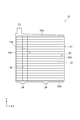
- FIG. 2 is a plan view of the positive electrode grid body.
- FIG. 3 is a plan view of the negative electrode grid body.
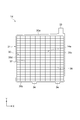
- FIG. 4 is a plan view of a state in which the positive electrode grid body and the negative electrode grid body are stacked.
- FIG. 5 is a figure which expands and shows a part of positive electrode grid body and negative electrode grid body of FIG.
- the lead storage battery 1 includes a case 2 having an open top surface, a lid 3 that closes the opening of the case 2, and an electrode group 4.
- the lead storage battery 1 is a control valve type lead storage battery. In the description of the lead storage battery 1, the direction in which the lid 3 is located is referred to as “up” for convenience.
- the case 2 and the lid 3 are made of, for example, polypropylene (PP), ABS and polyphenylene ether (PPE).
- the lid 3 is provided with a positive electrode terminal 5, a negative electrode terminal 6, and a control valve 7 for discharging excess gas to the outside of the case 2.
- the electrode group 4 and an electrolytic solution such as dilute sulfuric acid are contained.
- the electrode group 4 includes a positive electrode 9, a negative electrode 10, and a separator 11 arranged between the positive electrode 9 and the negative electrode 10.
- the electrode group 4 has a structure in which the positive electrodes 9 and the negative electrodes 10 are alternately stacked with the separators 11 in between.
- the distance between the positive electrode 9 and the negative electrode 10 is 2.0 mm or less when the positive electrode 9, the negative electrode 10 and the separator 11 are stacked and housed in the case 2.
- the positive electrode 9 and the negative electrode 10 are arranged so that their main surfaces are perpendicular to the opening surface of the case 2.
- the ears 23 of the positive electrode grid bodies 12 of the plurality of positive electrodes 9 are integrally welded to each other by the positive electrode strap 16.
- the ears 33 of the negative electrode grids 14 of the plurality of negative electrodes 10 are integrally welded by the negative electrode strap 17.
- the positive electrode strap 16 is connected to the positive electrode terminal 5 via the positive electrode column 18.
- the negative electrode strap 17 is connected to the negative electrode terminal 6 via the negative electrode column 19.
- the positive electrode 9 includes a positive electrode grid body 12 and a positive electrode material (electrode material) 13 filled in the positive electrode grid body 12.
- the positive electrode grid body 12 is a grid body used for the positive electrode 9 of the lead storage battery 1.
- the positive electrode grid 12 is made of, for example, a lead alloy containing lead as a main component.
- the lead alloy may contain one or more elements of antimony, tin, calcium and aluminum as a component other than lead.
- the lead alloy may further contain, for example, at least one of bismuth and silver.
- the positive electrode grid body 12 includes a frame body 21, a grid portion (positive electrode grid portion) 22, an ear portion 23, and a convex portion 24.
- the directions (X direction, Y direction) defined in FIG. 2 are used for description.
- the X direction corresponds to the first direction described in the claims.
- the Y direction corresponds to the second direction intersecting the first direction described in the claims.
- the frame 21 defines an internal space 12a for holding the positive electrode material 13.
- the frame body 21 is a rectangular frame.
- the frame body 21 includes a frame bone 25a, a frame bone 25b, a frame bone 25c, and a frame bone 25d.
- the frame bone 25a is an elongated columnar member that is located above the frame body 21 and extends along the X direction.
- the frame bone 25b is a long columnar member located below the frame body 21 and extending along the X direction.
- the frame bones 25a and 25b are arranged to face each other in the Y direction, and extend substantially parallel to each other along the X direction.
- Each of the frame bones 25a and 25b has, for example, a hexagonal prism shape. That is, the cross-sectional shape of the frame bone 25a that intersects the X direction and the cross-sectional shape of the frame bone 25b that intersects the X direction are hexagons.
- the frame bone 25c is a long columnar member located on the side of the frame body 21 and extending along the Y direction.
- the frame bone 25c connects one end of the frame bone 25a and one end of the frame bone 25b.
- the frame bone 25d is a long columnar member that is located on the side portion of the frame body 21 and extends along the Y direction.
- the frame bone 25d connects the other end of the frame bone 25a and the other end of the frame bone 25b.
- the frame bones 25c and 25d are arranged to face each other in the X direction and extend substantially parallel to each other along the Y direction.
- Each of the frame bones 25c and 25d has, for example, a hexagonal prism shape. That is, the cross-sectional shape of the frame bone 25c that intersects the Y direction and the cross-sectional shape of the frame bone 25d that intersects the Y direction are hexagons.
- the lattice portion 22 is provided in the internal space 12a and holds the positive electrode material 13.
- the lattice part 22 includes a plurality of lattice bones (first lattice bones) 26 and a plurality of lattice bones (second lattice bones) 27.
- Each of the plurality of lattice bones 26 is a long columnar member extending along the X direction.
- Each of the plurality of lattice bones 26 is arranged at a predetermined interval in the Y direction.
- Each of the plurality of lattice bones 27 is a long columnar member extending along the Y direction.
- Each of the plurality of lattice bones 27 is arranged at a predetermined interval in the X direction.
- the plurality of lattice bones 26 and the plurality of lattice bones 27 intersect each other and are arranged so as to form a lattice.
- Each of the lattice bones 26 and 27 has, for example, a hexagonal prism shape. That is, the cross-sectional shape of the lattice bone 26 that intersects the X direction and the cross-sectional shape of the lattice bone 27 that intersects the Y direction are hexagons.
- the ear portion 23 is a member for collecting current provided on the frame body 21.
- the ear portion 23 has a rectangular plate shape. Specifically, the ear portion 23 is provided on the frame bone 25a and protrudes upward from the frame bone 25a (on the side opposite to the frame bone 25b).
- the convex portion 24 is a plate-shaped member provided on the frame body 21. Specifically, the convex portion 24 is provided on the frame bone 25b and projects downward from the frame bone 25b (on the side opposite to the frame bone 25a). In this embodiment, two convex portions 24 are provided. The two convex portions 24 are arranged side by side in the X direction.
- the positive electrode material 13 contains a positive electrode active material, an additive, and the like.
- the positive electrode active material include lead dioxide.
- the additives include carbon materials and reinforcing short fibers.
- the negative electrode 10 has a negative electrode grid body 14 and a negative electrode material (electrode material) 15 filled in the negative electrode grid body 14.
- the negative electrode grid body 14 is a grid body used for the negative electrode 10 of the lead storage battery 1.
- the negative electrode grid 14 is made of, for example, a lead alloy containing lead as a main component.
- the lead alloy may contain one or more elements of antimony, tin, calcium and aluminum as a component other than lead.
- the lead alloy may further contain, for example, at least one of bismuth and silver.
- the negative electrode grid body 14 includes a frame body 31, a grid portion (negative electrode grid portion) 32, an ear portion 33, and a convex portion 34.
- the directions (X direction, Y direction) defined in FIG. 3 are used for description.
- the X direction corresponds to the first direction described in the claims.
- the Y direction corresponds to the second direction intersecting the first direction described in the claims.
- the frame 31 defines an internal space 14a for holding the negative electrode material 15.
- the frame body 31 is a rectangular frame.
- the frame body 31 includes a frame bone 35a, a frame bone 35b, a frame bone 35c, and a frame bone 35d.
- the frame bone 35a is a long columnar member that is located above the frame body 31 and extends along the X direction.
- the frame bone 35b is a long columnar member located below the frame body 31 and extending along the X direction.
- the frame bones 35a and 35b are arranged to face each other in the Y direction and extend substantially parallel to each other along the X direction.
- Each of the frame bones 35a and 35b has, for example, a hexagonal prism shape. That is, the cross-sectional shape of the frame bone 35a that intersects the X direction and the cross-sectional shape of the frame bone 35b that intersects the X direction are hexagons.
- the frame bone 35c is a long columnar member that is located on the side of the frame body 31 and extends along the Y direction.
- the frame bone 35c connects one end of the frame bone 35a and one end of the frame bone 35b.
- the frame bone 35d is a long columnar member that is located on a side portion of the frame body 31 and extends along the Y direction.
- the frame bone 35d connects the other end of the frame bone 35a and the other end of the frame bone 35b.
- the frame bones 35c and 35d are arranged to face each other in the X direction and extend substantially parallel to each other along the Y direction.
- Each of the frame bones 35c and 35d has, for example, a hexagonal prism shape. That is, the cross-sectional shape of the frame bone 35c that intersects the Y direction and the cross-sectional shape of the frame bone 35d that intersects the Y direction are hexagons.
- the lattice portion 32 is provided in the internal space 14a and holds the negative electrode material 15.
- the lattice portion 32 includes a plurality of lattice bones (third lattice bones) 36 and a plurality of lattice bones (fourth lattice bones) 37.
- Each of the plurality of lattice bones 36 is a long columnar member extending along the X direction.
- Each of the plurality of lattice bones 36 is arranged at a predetermined interval in the Y direction.
- Each of the plurality of lattice bones 37 is a long columnar member extending along the Y direction.
- Each of the plurality of lattice bones 37 is arranged at a predetermined interval in the X direction.
- the plurality of lattice bones 36 and the plurality of lattice bones 37 intersect each other and are arranged so as to form a lattice.
- Each of the lattice bones 36 and 37 has, for example, a hexagonal prism shape. That is, the cross-sectional shape of the lattice bone 36 that intersects the X direction and the cross-sectional shape of the lattice bone 37 that intersects the Y direction are hexagons.
- the ear portion 33 is a member for collecting current provided on the frame body 31.
- the ear portion 33 has a rectangular plate shape. Specifically, the ear portion 33 is provided on the frame bone 35a and projects from the frame bone 35a upward (to the side opposite to the frame bone 35b).
- the convex portion 34 is a plate-shaped member provided on the frame body 31. Specifically, the convex portion 34 is provided on the frame bone 35b and projects downward from the frame bone 35b (on the side opposite to the frame bone 35a). In this embodiment, two convex portions 34 are provided. The two convex portions 34 are arranged side by side in the X direction.
- the negative electrode material 15 contains a negative electrode active material, an additive, and the like.
- the negative electrode active material include spongy lead.
- the additive include barium sulfate, carbon materials, reinforcing short fibers, and the like.
- the separator 11 is, for example, an electrolytic solution holder (retainer) that holds an electrolytic solution such as dilute sulfuric acid.
- the separator 11 holds the electrolytic solution and allows sulfate ions and hydrogen ions (protons) to permeate while blocking electrical contact between the positive electrode 9 and the negative electrode 10.
- the separator 11 has a plate shape, but may have a bag shape capable of enclosing the positive electrode 9, for example.
- the thickness of each separator 11 is arbitrarily set and is, for example, 0.5 mm to 2.0 mm.
- FIG. 4 shows a state in which the positive electrode grid body 12 and the negative electrode grid body 14 are stacked.
- FIG. 5 is an enlarged view showing a part of the positive electrode grid body 12 and the negative electrode grid body 14 shown in FIG. In FIGS. 4 and 5, the direction in which the positive electrode grid body 12 and the negative electrode grid body 14 are stacked coincides with the direction in which the positive electrode 9, the negative electrode 10, and the separator 11 are stacked.
- the intersections C11 and C12 of one lattice bone of the lattice portion 22 and the lattice portion 32 include the lattice portion 22 and the lattice portion 32. It is located in the openings O1 and O2 formed by the other lattice bone.
- the area A is an area including the central portions of the lattice portion 22 and the lattice portion 32.
- the intersection portions C11 and C12 of one lattice bone of the lattice portion 22 and the lattice portion 32 are the lattice portion 22 and the lattice portion. It is located in the openings O1 and O2 formed by the other lattice bone of 32.
- the intersection portion C11 of the lattice bones 26 and the lattice bones 27 of the lattice portion 22 of the positive electrode 9 is the opening O1 formed by the lattice bones 36 and the lattice bones 37 of the lattice portion 32 of the negative electrode 10. Is located in.
- the intersecting portion C11 is located at the central portion C21 of the opening O1.
- the intersection portion C12 of the lattice bone 36 and the lattice bone 37 of the lattice portion 32 of the negative electrode 10 is located in the opening O2 formed by the lattice bones 26 and 27 of the lattice portion 22 of the positive electrode 9.
- the intersecting portion C12 is located at the central portion C22 of the opening O2.
- the central portions C21 and C22 may include not only the exact center but also surrounding areas including the center.
- the intersecting portion C11 of the lattice portion 22 and the intersecting portion C12 of the lattice portion 32 do not overlap with each other when viewed from the direction in which the positive electrode 9, the negative electrode 10, and the separator 11 are stacked. That is, in the lead storage battery 1, the grid bones 26 of the grid portion 22 and the grid bones 36 of the grid portion 32 do not overlap with each other when viewed from the direction in which the positive electrode 9, the negative electrode 10, and the separator 11 are stacked.
- the lattice bones 27 of the lattice portion 22 and the lattice bones 37 of the lattice portion 32 do not overlap each other when viewed from the direction in which the positive electrode 9, the negative electrode 10, and the separator 11 are stacked.
- one of the lattice portions 22 of the positive electrode lattice body 12 and the lattice portion 32 of the negative electrode lattice body 14 has the intersection portion C11, C12 of the lattice bones, which is the lattice portion. It is located in the openings O1 and O2 formed by the lattice bone of the other 22 and the lattice portion 32.
- the portion where the lattice bones 26 and 27 of the lattice portion 22 and the lattice bones 36 and 37 of the lattice portion 32 overlap can be reduced, and the lattice bones 26 and 27 of the lattice portion 22 and the lattice portion 32 can be reduced.
- the distance between the lattice bones 36 and 37 can be secured (the distance can be lengthened). Therefore, in the lead storage battery 1, even when the conductive portion (PbSO 4 ) is formed in the separator 11, it is possible to suppress the conduction between the positive electrode 9 and the negative electrode 10 by the conductive portion. As a result, in the lead storage battery 1, it is possible to prevent the occurrence of an infiltration short circuit.
- the intersecting portions C11 and C12 form the openings O1 and O2. positioned.
- the electrolytic solution is poured into the case 2 in which the positive electrode 9, the negative electrode 10, and the separator 11 are housed.
- the specific gravity of sulfuric acid tends to decrease. That is, in the area A, the permeation short circuit is likely to occur.
- the intersections C11, C12 should be located in the openings O1, O2 in the region A including the central portions of the grid portion 22 of the positive electrode grid body 12 and the grid portion 32 of the negative electrode grid body 14, respectively. This can effectively prevent the occurrence of an infiltration short circuit.
- the intersections C11, C12 are located at the central portions C21, C22 of the openings O1, O2.
- the lattice portion 22 of the positive electrode lattice body 12 has a plurality of lattice bones 26 and a plurality of lattice bones 27.
- the lattice portion 32 of the negative electrode lattice body 14 may include a plurality of lattice bones 36 and a plurality of lattice bones 37.
- the lattice bones 26 and the lattice bones 36 do not overlap, and the lattice bones 27 and the lattice bones 37 do not overlap. Therefore, in the lead storage battery 1, it is possible to prevent the occurrence of an infiltration short circuit.
- the distance between the positive electrode 9 and the negative electrode 10 which are arranged via the separator 11 in the case 2 is 2.0 mm or less.
- the thickness of the separator 11 is 2.0 mm or less.
- the lead storage battery 1 is a control valve type lead storage battery as an example.
- the lead storage battery may be a vented lead storage battery.
- the intersections C11 and C12 of one lattice bone of the lattice section 22 and the lattice section 32 are the lattice section 22 and the lattice section.
- the form positioned in the openings O1 and O2 formed by the other lattice bone of 32 has been described as an example.
- the intersections C11 and C12 of one lattice bone of the lattice portion 22 and the lattice portion 32 are formed by the other lattice bone of the lattice portion 22 and the lattice portion 32. It may be located at O1 and O2.
- the crossing portion C11 is located at the central portion C21 of the opening O1
- the crossing portion C12 is located at the central portion C22 of the opening O2.
- the intersections C11 and C12 may be located at least in the openings O1 and O2.
- the lattice portion 22 is composed of the linear lattice bones 26 and 27, and the lattice portion 32 is composed of the linear lattice bones 36 and 37. ..
- the structure of the lattice part is not limited to this.
- the lattice part may be manufactured by, for example, an expanding method.
- the present invention may appropriately combine the contents described as the above-mentioned embodiment and other modifications.
Landscapes
- Engineering & Computer Science (AREA)
- Manufacturing & Machinery (AREA)
- Chemical & Material Sciences (AREA)
- Chemical Kinetics & Catalysis (AREA)
- Electrochemistry (AREA)
- General Chemical & Material Sciences (AREA)
- Cell Electrode Carriers And Collectors (AREA)
Abstract
鉛蓄電池1では、正極格子体12は、複数の格子骨26,27で構成されている格子部22を有しており、負極格子体14は、複数の格子骨36,37で構成されている格子部32を有しており、正極9、負極10及びセパレータ11が積層されている方向から見て、格子部22及び格子部32の少なくとも一部の領域Aにおいて、格子部22及び格子部32のうちの一方の格子骨の交差部分C11,C12が、格子部22及び格子部32のうちの他方の格子骨によって形成されている開口部O1,O2に位置している。
Description
本発明は、鉛蓄電池に関する。
鉛蓄電池は、電極群と、電極群及び電解液を収容するケースと、を備えている(例えば、特許文献1参照)。電極群は、正極と負極とがセパレータを介して交互に積層された構造を有している。
現在、無停電電源及び電力貯蔵用途に、ローメンテナンスの制御弁式鉛蓄電池が用いられている。また、近年では、制御弁式鉛蓄電池は、電動車用等のサイクル用途でも利用されている。このようなサイクル用途には、高出力化が必要である。高出力化には、電極厚み、セパレータ厚み等を薄くすることで電槽内の電極枚数を増加させて対応している。
制御弁式鉛蓄電池の製造工程では、電槽化成が行われる。電槽化成では、未化成の電池に電解液を注入した後、直流電流を流している。電槽化成では、極板に電解液を浸透させるために、電解液を注入した後、所定時間放置している。この放置時間が長くなると、未化活物質と電解液(希硫酸)が反応することで硫酸鉛(PbSO4)が増加し、電解液の比重が低下する。電解液の比重が低くなると、硫酸鉛の溶解度が増加し、鉛イオン(Pb2+)が電解液中及び/又はセパレータ内の細孔に溶出する。この状態で充電を行うと、鉛イオンと硫酸イオン(SO4)とが反応して、セパレータの細孔内でPbSO4が析出し、正極と負極との間で導電箇所が形成されて浸透短絡が生じる。特に、セパレータの厚みが薄い場合には、浸透短絡が生じ易くなるといった課題がある。そのため、セパレータの厚みを薄くした場合において、電槽化成時等において浸透短絡の発生を抑制することが求められている。
本発明の一側面は、浸透短絡の発生を抑制できる鉛蓄電池を提供することを目的とする。
本発明の一側面に係る鉛蓄電池は、正極格子体と正極格子体に保持されている電極材とを有する正極と、負極格子体と負極格子体に保持されている電極材とを有する負極と、正極と負極との間に配置されたセパレータと、正極、負極、セパレータ及び電解液を収容するケースと、を備え、正極格子体は、複数の格子骨で構成されている正極格子部を有しており、負極格子体は、複数の格子骨で構成されている負極格子部を有しており、正極、負極及びセパレータが積層されている方向から見て、正極格子部及び負極格子部の少なくとも一部の領域において、正極格子部及び負極格子部のうちの一方の格子骨の交差部分が、正極格子部及び負極格子部のうちの他方の格子骨によって形成されている開口部に位置している。
本発明の一側面に係る鉛蓄電池では、正極格子部及び負極格子部のうちの一方の格子骨の交差部分が、正極格子部及び負極格子部のうちの他方の格子骨によって形成されている開口部に位置している。そのため、鉛蓄電池では、正極格子部の格子骨と負極格子部の格子骨とが重なる部分を少なくすることができ、正極格子部の格子骨と負極格子部の格子骨との間の距離を確保できる。したがって、鉛蓄電池では、セパレータ内に導電箇所が形成された場合であっても、正極と負極とが当該導電箇所によって導通することを抑制できる。その結果、鉛蓄電池では、浸透短絡の発生を防止できる。
一実施形態においては、正極格子部及び負極格子部のそれぞれの中央部を含む前記領域において、交差部分が開口部に位置していてもよい。正極格子部及び負極格子部のそれぞれの中央部を含む領域は、正極、負極及びセパレータが収容されたケースに電解液が注液されたときに、硫酸比重の低下が生じ易い。そのため、鉛蓄電池では、正極格子部及び負極格子部のそれぞれの中央部を含む領域において、交差部分を開口部に位置させることによって、浸透短絡の発生を効果的に防止できる。
一実施形態においては、交差部分は、開口部の中央部に位置していてもよい。この構成では、正極格子部の格子骨と負極格子部の格子骨との間の距離を確保できる。したがって、鉛蓄電池では、浸透短絡の発生をより一層防止できる。
一実施形態においては、正極格子部は、第一方向に沿って延在していると共に第一方向に交差する第二方向において所定の間隔をあけて配置されている複数の第一格子骨と、第二方向に沿って延在していると共に第一方向において所定の間隔をあけて配置されている複数の第二格子骨と、を有しており、負極格子部は、第一方向に沿って延在していると共に第二方向において所定の間隔を開けて配置されている複数の第三格子骨と、第二方向に沿って延在していると共に第一方向において所定の間隔をあけて配置されている複数の第四格子骨と、を有していてもよい。この構成では、交差部分を開口部に位置させることによって、第一格子骨と第三格子骨とが重ならず、第二格子骨と第四格子骨とが重ならない。したがって、鉛蓄電池では、浸透短絡の発生を防止できる。
一実施形態においては、セパレータを介して配置されている正極と負極との間の距離は、2.0mm以下であってもよい。このように、正極と負極との間の距離が短い場合には、交差部分を開口部に位置させる構成が特に有効である。
一実施形態においては、セパレータの厚みは、2.0mm以下であってもよい。このように、セパレータの厚みが薄い場合には、交差部分を開口部に位置させる構成が特に有効である。
一実施形態においては、ケースに制御弁が設けられていてもよい。制御弁を有する制御弁式鉛蓄電池では、浸透短絡が発生し得る。したがって、制御弁式鉛蓄電池では、交差部分を開口部に位置させる構成が特に有効である。
本発明の一側面によれば、浸透短絡の発生を防止できる。
以下、添付図面を参照して、本発明の好適な実施形態について詳細に説明する。なお、図面の説明において同一又は相当要素には同一符号を付し、重複する説明は省略する。
図1に示されるように、鉛蓄電池1は、上面が開口しているケース2と、ケース2の開口を塞ぐ蓋3と、電極群4と、を備えている。鉛蓄電池1は、制御弁式鉛蓄電池である。なお、鉛蓄電池1の説明において、蓋3が位置する方向を便宜上、「上」としている。
ケース2及び蓋3は、例えば、ポリプロピレン(PP)、ABS及びポリフェニレンエーテル(PPE)で形成されている。蓋3には、正極端子5と、負極端子6と、過剰なガスをケース2外に排出するための制御弁7と、が設けられている。ケース2の内部には、電極群4と、希硫酸等の電解液と、が収容されている。
電極群4は、正極9と、負極10と、正極9と負極10との間に配置されたセパレータ11と、を備えている。具体的には、電極群4は、正極9と負極10とがセパレータ11を介して交互に積層された構造を有している。電極群4では、正極9、負極10及びセパレータ11が積層されてケース2内に収容された状態において、正極9と負極10との間の距離が2.0mm以下である。
正極9及び負極10は、それらの主面がケース2の開口面と垂直になるように配置されている。電極群4において、複数の正極9における各正極格子体12が有する耳部23同士は、正極ストラップ16で一体的に溶接されている。同様に、複数の負極10における各負極格子体14が有する耳部33同士は、負極ストラップ17で一体的に溶接されている。正極ストラップ16は、正極柱18を介して正極端子5に接続されている。負極ストラップ17は、負極柱19を介して負極端子6に接続されている。
正極9は、正極格子体12と、正極格子体12に充填された正極材(電極材)13と、を備えている。正極格子体12は、鉛蓄電池1の正極9に用いられる格子体である。正極格子体12は、例えば鉛を主成分として含む鉛合金から構成されている。鉛合金は、鉛以外の成分として、アンチモン、錫、カルシウム及びアルミニウムのうちの一種以上の元素を含んでもよい。鉛合金は、例えばビスマス及び銀の少なくとも何れかをさらに含有してもよい。
図2に示されるように、正極格子体12は、枠体21と、格子部(正極格子部)22と、耳部23と、凸部24と、を備えている。以下の説明においては、図2で規定する方向(X方向、Y方向)を説明に用いる。X方向は、請求の範囲に記載の、第一方向に対応する。Y方向は、請求項の範囲に記載の、第一方向に交差する第二方向に対応する。
枠体21は、正極材13を保持するための内部空間12aを規定する。枠体21は、矩形状の枠である。枠体21は、枠骨25aと、枠骨25bと、枠骨25cと、枠骨25dと、を備えている。枠骨25aは、枠体21の上部に位置し、X方向に沿って延びる長尺の柱状部材である。枠骨25bは、枠体21の下部に位置し、X方向に沿って延びる長尺の柱状部材である。枠骨25aと枠骨25bとは、Y方向に対向して配置されており、X方向に沿って互いに略平行に延びている。枠骨25a及び枠骨25bのそれぞれは、例えば、六角柱の形状を有している。つまり、枠骨25aのX方向と交差する断面形状及び枠骨25bのX方向と交差する断面形状は、六角形である。
枠骨25cは、枠体21の側部に位置し、Y方向に沿って延びる長尺の柱状部材である。枠骨25cは、枠骨25aの一端と枠骨25bの一端とを連結している。枠骨25dは、枠体21の側部に位置し、Y方向に沿って延びる長尺の柱状部材である。枠骨25dは、枠骨25aの他端と枠骨25bの他端とを連結している。枠骨25cと枠骨25dとは、X方向に対向して配置されており、Y方向に沿って互いに略平行に延びている。枠骨25c及び枠骨25dのそれぞれは、例えば、六角柱の形状を有している。つまり、枠骨25cのY方向と交差する断面形状及び枠骨25dのY方向と交差する断面形状は、六角形である。
格子部22は、内部空間12aに設けられ、正極材13を保持する。格子部22は、複数の格子骨(第一格子骨)26と、複数の格子骨(第二格子骨)27と、を備えている。複数の格子骨26のそれぞれは、X方向に沿って延びる長尺の柱状部材である。複数の格子骨26のそれぞれは、Y方向において所定の間隔をあけて配置されている。複数の格子骨27のそれぞれは、Y方向に沿って延びる長尺の柱状部材である。複数の格子骨27のそれぞれは、X方向において所定の間隔をあけて配置されている。複数の格子骨26と、複数の格子骨27とは、互いに交差しており、格子を成すように配置されている。格子骨26及び格子骨27のそれぞれは、例えば、六角柱の形状を有している。つまり、格子骨26のX方向と交差する断面形状及び格子骨27のY方向と交差する断面形状は、六角形である。
耳部23は、枠体21に設けられた集電用の部材である。耳部23は、矩形板状を呈している。具体的には、耳部23は、枠骨25aに設けられており、枠骨25aから上方(枠骨25bと反対側)に向かって突出している。凸部24は、枠体21に設けられた板状部材である。具体的には、凸部24は、枠骨25bに設けられており、枠骨25bから下方(枠骨25aと反対側)に向かって突出している。本実施形態では、二つの凸部24が設けられている。二つの凸部24は、X方向に並んで配置されている。
図1に示されるように、正極材13は、正極活物質及び添加剤等を含む。正極活物質としては、二酸化鉛等が挙げられる。添加剤としては、炭素材料及び補強用短繊維等が挙げられる。
負極10は、負極格子体14と、負極格子体14に充填された負極材(電極材)15と、を有している。負極格子体14は、鉛蓄電池1の負極10に用いられる格子体である。負極格子体14は、例えば鉛を主成分として含む鉛合金から構成されている。鉛合金は、鉛以外の成分として、アンチモン、錫、カルシウム及びアルミニウムのうちの一種以上の元素を含んでもよい。鉛合金は、例えばビスマス及び銀の少なくとも何れかをさらに含有してもよい。
図3に示されるように、負極格子体14は、枠体31と、格子部(負極格子部)32と、耳部33と、凸部34と、を備えている。以下の説明においては、図3で規定する方向(X方向、Y方向)を説明に用いる。X方向は、請求の範囲に記載の、第一方向に対応する。Y方向は、請求項の範囲に記載の、第一方向に交差する第二方向に対応する。
枠体31は、負極材15を保持するための内部空間14aを規定する。枠体31は、矩形状の枠である。枠体31は、枠骨35aと、枠骨35bと、枠骨35cと、枠骨35dと、を備えている。枠骨35aは、枠体31の上部に位置し、X方向に沿って延びる長尺の柱状部材である。枠骨35bは、枠体31の下部に位置し、X方向に沿って延びる長尺の柱状部材である。枠骨35aと枠骨35bとは、Y方向に対向して配置されており、X方向に沿って互いに略平行に延びている。枠骨35a及び枠骨35bのそれぞれは、例えば、六角柱の形状を有している。つまり、枠骨35aのX方向と交差する断面形状及び枠骨35bのX方向と交差する断面形状は、六角形である。
枠骨35cは、枠体31の側部に位置し、Y方向に沿って延びる長尺の柱状部材である。枠骨35cは、枠骨35aの一端と枠骨35bの一端とを連結している。枠骨35dは、枠体31の側部に位置し、Y方向に沿って延びる長尺の柱状部材である。枠骨35dは、枠骨35aの他端と枠骨35bの他端とを連結している。枠骨35cと枠骨35dとは、X方向に対向して配置されており、Y方向に沿って互いに略平行に延びている。枠骨35c及び枠骨35dのそれぞれは、例えば、六角柱の形状を有している。つまり、枠骨35cのY方向と交差する断面形状及び枠骨35dのY方向と交差する断面形状は、六角形である。
格子部32は、内部空間14aに設けられ、負極材15を保持する。格子部32は、複数の格子骨(第三格子骨)36と、複数の格子骨(第四格子骨)37と、を備えている。複数の格子骨36のそれぞれは、X方向に沿って延びる長尺の柱状部材である。複数の格子骨36のそれぞれは、Y方向において所定の間隔をあけて配置されている。複数の格子骨37のそれぞれは、Y方向に沿って延びる長尺の柱状部材である。複数の格子骨37のそれぞれは、X方向において所定の間隔をあけて配置されている。複数の格子骨36と、複数の格子骨37とは、互いに交差しており、格子を成すように配置されている。格子骨36及び格子骨37のそれぞれは、例えば、六角柱の形状を有している。つまり、格子骨36のX方向と交差する断面形状及び格子骨37のY方向と交差する断面形状は、六角形である。
耳部33は、枠体31に設けられた集電用の部材である。耳部33は、矩形板状を呈している。具体的には、耳部33は、枠骨35aに設けられており、枠骨35aから上方(枠骨35bと反対側)に向かって突出している。凸部34は、枠体31に設けられた板状部材である。具体的には、凸部34は、枠骨35bに設けられており、枠骨35bから下方(枠骨35aと反対側)に向かって突出している。本実施形態では、二つの凸部34が設けられている。二つの凸部34は、X方向に並んで配置されている。
図1に示されるように、負極材15は、負極活物質及び添加剤等を含む。負極活物質としては、海綿状鉛(Spongylead)等が挙げられる。添加剤としては、硫酸バリウム、炭素材料及び補強用短繊維等が挙げられる。
セパレータ11は、例えば、希硫酸等の電解液を保持する電解液保持体(リテーナ)である。セパレータ11は、正極9と負極10との間の電気的な接触を阻止しつつ、電解液を保持して硫酸イオン及び水素イオン(プロトン)を透過させる。本実施形態では、セパレータ11は、板状であるが、例えば正極9を包むことが可能な袋状であってもよい。セパレータ11の一枚あたりの厚さは、任意に設定されるが、例えば0.5mm~2.0mmである。
図4は、正極格子体12と負極格子体14とが重ねられた状態を示している。図5は、図4に示す正極格子体12及び負極格子体14の一部を拡大して示す図である。図4及び図5において、正極格子体12と負極格子体14とが重ねられている方向は、正極9、負極10及びセパレータ11が積層されている方向に一致している。
図4及び図5に示されるように、鉛蓄電池1では、正極格子体12と負極格子体14とが重ねられている方向、すなわち正極9、負極10及びセパレータ11が積層されている方向から見て、格子部22及び格子部32の少なくとも一部の領域Aにおいて、格子部22及び格子部32のうちの一方の格子骨の交差部分C11,C12が、格子部22及び格子部32のうちの他方の格子骨によって形成されている開口部O1,O2に位置している。領域Aは、格子部22及び格子部32のそれぞれの中央部を含む領域である。本実施形態では、領域Aを含む格子部22及び格子部32の全ての領域において、格子部22及び格子部32のうちの一方の格子骨の交差部分C11,C12が、格子部22及び格子部32のうちの他方の格子骨によって形成されている開口部O1,O2に位置している。
図5に示されるように、正極9の格子部22の格子骨26及び格子骨27の交差部分C11は、負極10の格子部32の格子骨36及び格子骨37によって形成されている開口部O1に位置している。本実施形態では、交差部分C11は、開口部O1の中央部C21に位置している。負極10の格子部32の格子骨36及び格子骨37の交差部分C12は、正極9の格子部22の格子骨26及び格子骨27によって形成されている開口部O2に位置している。本実施形態では、交差部分C12は、開口部O2の中央部C22に位置している。なお、中央部C21,C22とは、厳密に中央であることだけでなく、中央を含む周囲の領域を含み得る。
このような構成により、格子部22の交差部分C11と格子部32の交差部分C12とは、正極9、負極10及びセパレータ11が積層されている方向から見て重なっていない。すなわち、鉛蓄電池1では、正極9、負極10及びセパレータ11が積層されている方向から見て、格子部22の格子骨26と格子部32の格子骨36とが重なっていない。また、鉛蓄電池1では、正極9、負極10及びセパレータ11が積層されている方向から見て、格子部22の格子骨27と格子部32の格子骨37とが重なっていない。
以上説明したように、本実施形態に係る鉛蓄電池1では、正極格子体12の格子部22及び負極格子体14の格子部32のうちの一方の格子骨の交差部分C11,C12が、格子部22及び格子部32のうちの他方の格子骨によって形成されている開口部O1,O2に位置している。そのため、鉛蓄電池1では、格子部22の格子骨26,27と格子部32の格子骨36,37とが重なる部分を少なくすることができ、格子部22の格子骨26,27と格子部32の格子骨36,37との間の距離を確保できる(距離を長くできる)。したがって、鉛蓄電池1では、セパレータ11内に導電箇所(PbSO4)が形成された場合であっても、正極9と負極10とが当該導電箇所によって導通することを抑制できる。その結果、鉛蓄電池1では、浸透短絡の発生を防止できる。
本実施形態に係る鉛蓄電池1では、正極格子体12の格子部22及び負極格子体14の格子部32のそれぞれの中央部を含む領域Aにおいて、交差部分C11,C12が開口部O1,O2に位置している。正極格子体12の格子部22及び負極格子体14の格子部32のそれぞれの中央部を含む領域Aは、正極9、負極10及びセパレータ11が収容されたケース2に電解液が注液されたときに、硫酸比重の低下が生じ易い。すなわち、領域Aでは、浸透短絡が発生し易い。そのため、鉛蓄電池1では、正極格子体12の格子部22及び負極格子体14の格子部32のそれぞれの中央部を含む領域Aにおいて、交差部分C11,C12を開口部O1,O2に位置させることによって、浸透短絡の発生を効果的に防止できる。
本実施形態に係る鉛蓄電池1では、交差部分C11,C12は、開口部O1,O2の中央部C21,C22に位置している。この構成では、格子部22の格子骨26,27と格子部32の格子骨36,37との間の距離を確保できる。したがって、鉛蓄電池1では、浸透短絡の発生をより一層防止できる。
本実施形態に係る鉛蓄電池1では、正極格子体12の格子部22は、複数の格子骨26と、複数の格子骨27と、を有している。負極格子体14の格子部32は、複数の格子骨36と、複数の格子骨37と、を有していてもよい。この構成では、交差部分C11,C12を開口部O1,O2に位置させることによって、格子骨26と格子骨36とが重ならず、格子骨27と格子骨37とが重ならない。したがって、鉛蓄電池1では、浸透短絡の発生を防止できる。
本実施形態に係る鉛蓄電池1では、ケース2内において、セパレータ11を介して配置されている正極9と負極10との間の距離は、2.0mm以下である。セパレータ11の厚みは、2.0mm以下である。このように、正極9と負極10との間の距離が短い場合には、交差部分C11,C12を開口部O1,O2に位置させる構成が特に有効である。
以上、本発明の実施形態について説明してきたが、本発明は必ずしも上述した実施形態に限定されるものではなく、その要旨を逸脱しない範囲で様々な変更が可能である。
上記実施形態では、鉛蓄電池1が制御弁式鉛蓄電池である形態を一例に説明した。しかし、鉛蓄電池は、ベント形鉛蓄電池であってもよい。
上記実施形態では、領域Aを含む格子部22及び格子部32の全ての領域において、格子部22及び格子部32のうちの一方の格子骨の交差部分C11,C12が、格子部22及び格子部32のうちの他方の格子骨によって形成されている開口部O1,O2に位置している形態を一例に説明した。しかし、少なくとも領域Aにおいて、格子部22及び格子部32のうちの一方の格子骨の交差部分C11,C12が、格子部22及び格子部32のうちの他方の格子骨によって形成されている開口部O1,O2に位置していてもよい。
上記実施形態では、交差部分C11が開口部O1の中央部C21に位置しており、交差部分C12が開口部O2の中央部C22に位置している形態を一例に説明した。しかし、交差部分C11,C12は、少なくとも開口部O1,O2に位置していればよい。
上記実施形態では、格子部22が直線状の格子骨26及び格子骨27によって構成されており、格子部32が直線状の格子骨36及び格子骨37によって構成されている形態を一例に説明した。しかし、格子部の構造はこれに限定されない。格子部は、例えば、エキスパンド方式によって製造されてもよい。
本発明は、上記実施形態及びその他の変形例として記載の内容を適宜組み合わせてもよい。
1…鉛蓄電池、2…ケース、7…制御弁、9…正極、10…負極、11…セパレータ、12…正極格子体、13…正極材、14…負極格子体、15…負極材、22…格子部(正極格子部)、26…格子骨(第一格子骨)、27…格子骨(第二格子骨)、32…格子部、36…格子骨(第三格子骨)、37…格子骨(第四格子骨)、A…領域、C11,C12…交差部分、C21,C22…中央部、O1,O2…開口部。
Claims (7)
- 正極格子体と前記正極格子体に保持されている電極材とを有する正極と、
負極格子体と前記負極格子体に保持されている電極材とを有する負極と、
前記正極と前記負極との間に配置されたセパレータと、
前記正極、前記負極、前記セパレータ及び電解液を収容するケースと、を備え、
前記正極格子体は、複数の格子骨で構成されている正極格子部を有しており、
前記負極格子体は、複数の格子骨で構成されている負極格子部を有しており、
前記正極、前記負極及び前記セパレータが積層されている方向から見て、前記正極格子部及び前記負極格子部の少なくとも一部の領域において、前記正極格子部及び前記負極格子部のうちの一方の前記格子骨の交差部分が、前記正極格子部及び前記負極格子部のうちの他方の前記格子骨によって形成されている開口部に位置している、鉛蓄電池。 - 前記正極格子部及び前記負極格子部のそれぞれの中央部を含む前記領域において、前記交差部分が前記開口部に位置している、請求項1に記載の鉛蓄電池。
- 前記交差部分は、前記開口部の中央部に位置している、請求項1又は2に記載の鉛蓄電池。
- 前記正極格子部は、第一方向に沿って延在していると共に前記第一方向に交差する第二方向において所定の間隔をあけて配置されている複数の第一格子骨と、前記第二方向に沿って延在していると共に前記第一方向において所定の間隔をあけて配置されている複数の第二格子骨と、を有しており、
前記負極格子部は、前記第一方向に沿って延在していると共に前記第二方向において所定の間隔を開けて配置されている複数の第三格子骨と、前記第二方向に沿って延在していると共に前記第一方向において所定の間隔をあけて配置されている複数の第四格子骨と、を有している、請求項1~3のいずれか一項に記載の鉛蓄電池。 - 前記セパレータを介して配置されている前記正極と前記負極との間の距離は、2.0mm以下である、請求項1~4のいずれか一項に記載の鉛蓄電池。
- 前記セパレータの厚みは、2.0mm以下である、請求項1~5のいずれか一項に記載の鉛蓄電池。
- 前記ケースに制御弁が設けられている、請求項1~6のいずれか一項に記載の鉛蓄電池。
Priority Applications (1)
| Application Number | Priority Date | Filing Date | Title |
|---|---|---|---|
| PCT/JP2019/001112 WO2020148834A1 (ja) | 2019-01-16 | 2019-01-16 | 鉛蓄電池 |
Applications Claiming Priority (1)
| Application Number | Priority Date | Filing Date | Title |
|---|---|---|---|
| PCT/JP2019/001112 WO2020148834A1 (ja) | 2019-01-16 | 2019-01-16 | 鉛蓄電池 |
Publications (1)
| Publication Number | Publication Date |
|---|---|
| WO2020148834A1 true WO2020148834A1 (ja) | 2020-07-23 |
Family
ID=71614165
Family Applications (1)
| Application Number | Title | Priority Date | Filing Date |
|---|---|---|---|
| PCT/JP2019/001112 Ceased WO2020148834A1 (ja) | 2019-01-16 | 2019-01-16 | 鉛蓄電池 |
Country Status (1)
| Country | Link |
|---|---|
| WO (1) | WO2020148834A1 (ja) |
Citations (1)
| Publication number | Priority date | Publication date | Assignee | Title |
|---|---|---|---|---|
| JP2007184114A (ja) * | 2005-12-29 | 2007-07-19 | Furukawa Battery Co Ltd:The | 制御弁式鉛蓄電池 |
-
2019
- 2019-01-16 WO PCT/JP2019/001112 patent/WO2020148834A1/ja not_active Ceased
Patent Citations (1)
| Publication number | Priority date | Publication date | Assignee | Title |
|---|---|---|---|---|
| JP2007184114A (ja) * | 2005-12-29 | 2007-07-19 | Furukawa Battery Co Ltd:The | 制御弁式鉛蓄電池 |
Non-Patent Citations (1)
| Title |
|---|
| YOSHINO, AKIRA: "Viewpoint of Battery Technology", SEN-ITO KOGYO, vol. 66, no. 1, 2010, pages 2 - 3 * |
Similar Documents
| Publication | Publication Date | Title |
|---|---|---|
| JP6638795B2 (ja) | 鉛蓄電池及びその製造方法 | |
| JP6519161B2 (ja) | 蓄電素子 | |
| CN101322278B (zh) | 锂离子二次电池 | |
| US12451493B2 (en) | Battery grid | |
| JP2016085912A (ja) | 蓄電素子 | |
| KR20180034660A (ko) | 납 축전지 | |
| WO2017159299A1 (ja) | 鉛蓄電池 | |
| JP2009516325A (ja) | 区画された電解質を有するリチウム2次電池 | |
| WO2020148834A1 (ja) | 鉛蓄電池 | |
| JP3245022B2 (ja) | 鉛蓄電池及びその製造方法 | |
| US20130130104A1 (en) | Current collector, energy storage element, and method of manufacturing current collector | |
| WO2019225620A1 (ja) | 鉛蓄電池 | |
| JP2019133845A (ja) | 鉛蓄電池 | |
| KR102451931B1 (ko) | 납축전지의 극판 성장에 따른 쇼트를 방지하기 위한 이종 합성수지 재질로 형성된 쇼트 방지 장치 | |
| WO2022230902A1 (ja) | 組電池、組電池の製造方法、及び組電池の製造装置 | |
| JP7787649B2 (ja) | 組電池、組電池の製造方法、及び組電池の製造装置 | |
| US20250023209A1 (en) | Strap structures for battery, battery and assembly comprising the same | |
| JP6999430B2 (ja) | 鉛蓄電池 | |
| JPH0532939Y2 (ja) | ||
| JP2022169203A (ja) | 組電池 | |
| JP7185981B2 (ja) | 格子体及び鉛蓄電池 | |
| JP5041460B2 (ja) | 鉛蓄電池 | |
| EP4106063A1 (en) | Square secondary battery | |
| JP2026014709A (ja) | 制御弁式鉛蓄電池、及び制御弁式鉛蓄電池の電槽 | |
| JPH04284366A (ja) | 密閉型鉛蓄電池 |
Legal Events
| Date | Code | Title | Description |
|---|---|---|---|
| 121 | Ep: the epo has been informed by wipo that ep was designated in this application |
Ref document number: 19910354 Country of ref document: EP Kind code of ref document: A1 |
|
| NENP | Non-entry into the national phase |
Ref country code: DE |
|
| 32PN | Ep: public notification in the ep bulletin as address of the adressee cannot be established |
Free format text: NOTING OF LOSS OF RIGHTS PURSUANT TO RULE 112(1) EPC (EPO FORM 1205A DATED 12-10-2021) |
|
| NENP | Non-entry into the national phase |
Ref country code: JP |
|
| 122 | Ep: pct application non-entry in european phase |
Ref document number: 19910354 Country of ref document: EP Kind code of ref document: A1 |