WO2020145207A1 - 真空処理装置、真空処理装置のクリーニング方法 - Google Patents
真空処理装置、真空処理装置のクリーニング方法 Download PDFInfo
- Publication number
- WO2020145207A1 WO2020145207A1 PCT/JP2019/051474 JP2019051474W WO2020145207A1 WO 2020145207 A1 WO2020145207 A1 WO 2020145207A1 JP 2019051474 W JP2019051474 W JP 2019051474W WO 2020145207 A1 WO2020145207 A1 WO 2020145207A1
- Authority
- WO
- WIPO (PCT)
- Prior art keywords
- shower plate
- gas
- plate
- electrode
- slide
- Prior art date
- Legal status (The legal status is an assumption and is not a legal conclusion. Google has not performed a legal analysis and makes no representation as to the accuracy of the status listed.)
- Ceased
Links
Images


Classifications
-
- H—ELECTRICITY
- H01—ELECTRIC ELEMENTS
- H01J—ELECTRIC DISCHARGE TUBES OR DISCHARGE LAMPS
- H01J37/00—Discharge tubes with provision for introducing objects or material to be exposed to the discharge, e.g. for the purpose of examination or processing thereof
- H01J37/32—Gas-filled discharge tubes
- H01J37/32431—Constructional details of the reactor
- H01J37/32532—Electrodes
- H01J37/32559—Protection means, e.g. coatings
-
- C—CHEMISTRY; METALLURGY
- C23—COATING METALLIC MATERIAL; COATING MATERIAL WITH METALLIC MATERIAL; CHEMICAL SURFACE TREATMENT; DIFFUSION TREATMENT OF METALLIC MATERIAL; COATING BY VACUUM EVAPORATION, BY SPUTTERING, BY ION IMPLANTATION OR BY CHEMICAL VAPOUR DEPOSITION, IN GENERAL; INHIBITING CORROSION OF METALLIC MATERIAL OR INCRUSTATION IN GENERAL
- C23C—COATING METALLIC MATERIAL; COATING MATERIAL WITH METALLIC MATERIAL; SURFACE TREATMENT OF METALLIC MATERIAL BY DIFFUSION INTO THE SURFACE, BY CHEMICAL CONVERSION OR SUBSTITUTION; COATING BY VACUUM EVAPORATION, BY SPUTTERING, BY ION IMPLANTATION OR BY CHEMICAL VAPOUR DEPOSITION, IN GENERAL
- C23C16/00—Chemical coating by decomposition of gaseous compounds, without leaving reaction products of surface material in the coating, i.e. chemical vapour deposition [CVD] processes
- C23C16/22—Chemical coating by decomposition of gaseous compounds, without leaving reaction products of surface material in the coating, i.e. chemical vapour deposition [CVD] processes characterised by the deposition of inorganic material, other than metallic material
- C23C16/30—Deposition of compounds, mixtures or solid solutions, e.g. borides, carbides, nitrides
- C23C16/40—Oxides
- C23C16/405—Oxides of refractory metals or yttrium
-
- C—CHEMISTRY; METALLURGY
- C23—COATING METALLIC MATERIAL; COATING MATERIAL WITH METALLIC MATERIAL; CHEMICAL SURFACE TREATMENT; DIFFUSION TREATMENT OF METALLIC MATERIAL; COATING BY VACUUM EVAPORATION, BY SPUTTERING, BY ION IMPLANTATION OR BY CHEMICAL VAPOUR DEPOSITION, IN GENERAL; INHIBITING CORROSION OF METALLIC MATERIAL OR INCRUSTATION IN GENERAL
- C23C—COATING METALLIC MATERIAL; COATING MATERIAL WITH METALLIC MATERIAL; SURFACE TREATMENT OF METALLIC MATERIAL BY DIFFUSION INTO THE SURFACE, BY CHEMICAL CONVERSION OR SUBSTITUTION; COATING BY VACUUM EVAPORATION, BY SPUTTERING, BY ION IMPLANTATION OR BY CHEMICAL VAPOUR DEPOSITION, IN GENERAL
- C23C16/00—Chemical coating by decomposition of gaseous compounds, without leaving reaction products of surface material in the coating, i.e. chemical vapour deposition [CVD] processes
- C23C16/44—Chemical coating by decomposition of gaseous compounds, without leaving reaction products of surface material in the coating, i.e. chemical vapour deposition [CVD] processes characterised by the method of coating
- C23C16/4401—Means for minimising impurities, e.g. dust, moisture or residual gas, in the reaction chamber
- C23C16/4405—Cleaning of reactor or parts inside the reactor by using reactive gases
-
- C—CHEMISTRY; METALLURGY
- C23—COATING METALLIC MATERIAL; COATING MATERIAL WITH METALLIC MATERIAL; CHEMICAL SURFACE TREATMENT; DIFFUSION TREATMENT OF METALLIC MATERIAL; COATING BY VACUUM EVAPORATION, BY SPUTTERING, BY ION IMPLANTATION OR BY CHEMICAL VAPOUR DEPOSITION, IN GENERAL; INHIBITING CORROSION OF METALLIC MATERIAL OR INCRUSTATION IN GENERAL
- C23C—COATING METALLIC MATERIAL; COATING MATERIAL WITH METALLIC MATERIAL; SURFACE TREATMENT OF METALLIC MATERIAL BY DIFFUSION INTO THE SURFACE, BY CHEMICAL CONVERSION OR SUBSTITUTION; COATING BY VACUUM EVAPORATION, BY SPUTTERING, BY ION IMPLANTATION OR BY CHEMICAL VAPOUR DEPOSITION, IN GENERAL
- C23C16/00—Chemical coating by decomposition of gaseous compounds, without leaving reaction products of surface material in the coating, i.e. chemical vapour deposition [CVD] processes
- C23C16/44—Chemical coating by decomposition of gaseous compounds, without leaving reaction products of surface material in the coating, i.e. chemical vapour deposition [CVD] processes characterised by the method of coating
- C23C16/4401—Means for minimising impurities, e.g. dust, moisture or residual gas, in the reaction chamber
- C23C16/4408—Means for minimising impurities, e.g. dust, moisture or residual gas, in the reaction chamber by purging residual gases from the reaction chamber or gas lines
-
- C—CHEMISTRY; METALLURGY
- C23—COATING METALLIC MATERIAL; COATING MATERIAL WITH METALLIC MATERIAL; CHEMICAL SURFACE TREATMENT; DIFFUSION TREATMENT OF METALLIC MATERIAL; COATING BY VACUUM EVAPORATION, BY SPUTTERING, BY ION IMPLANTATION OR BY CHEMICAL VAPOUR DEPOSITION, IN GENERAL; INHIBITING CORROSION OF METALLIC MATERIAL OR INCRUSTATION IN GENERAL
- C23C—COATING METALLIC MATERIAL; COATING MATERIAL WITH METALLIC MATERIAL; SURFACE TREATMENT OF METALLIC MATERIAL BY DIFFUSION INTO THE SURFACE, BY CHEMICAL CONVERSION OR SUBSTITUTION; COATING BY VACUUM EVAPORATION, BY SPUTTERING, BY ION IMPLANTATION OR BY CHEMICAL VAPOUR DEPOSITION, IN GENERAL
- C23C16/00—Chemical coating by decomposition of gaseous compounds, without leaving reaction products of surface material in the coating, i.e. chemical vapour deposition [CVD] processes
- C23C16/44—Chemical coating by decomposition of gaseous compounds, without leaving reaction products of surface material in the coating, i.e. chemical vapour deposition [CVD] processes characterised by the method of coating
- C23C16/448—Chemical coating by decomposition of gaseous compounds, without leaving reaction products of surface material in the coating, i.e. chemical vapour deposition [CVD] processes characterised by the method of coating characterised by the method used for generating reactive gas streams, e.g. by evaporation or sublimation of precursor materials
- C23C16/452—Chemical coating by decomposition of gaseous compounds, without leaving reaction products of surface material in the coating, i.e. chemical vapour deposition [CVD] processes characterised by the method of coating characterised by the method used for generating reactive gas streams, e.g. by evaporation or sublimation of precursor materials by activating reactive gas streams before their introduction into the reaction chamber, e.g. by ionisation or addition of reactive species
-
- C—CHEMISTRY; METALLURGY
- C23—COATING METALLIC MATERIAL; COATING MATERIAL WITH METALLIC MATERIAL; CHEMICAL SURFACE TREATMENT; DIFFUSION TREATMENT OF METALLIC MATERIAL; COATING BY VACUUM EVAPORATION, BY SPUTTERING, BY ION IMPLANTATION OR BY CHEMICAL VAPOUR DEPOSITION, IN GENERAL; INHIBITING CORROSION OF METALLIC MATERIAL OR INCRUSTATION IN GENERAL
- C23C—COATING METALLIC MATERIAL; COATING MATERIAL WITH METALLIC MATERIAL; SURFACE TREATMENT OF METALLIC MATERIAL BY DIFFUSION INTO THE SURFACE, BY CHEMICAL CONVERSION OR SUBSTITUTION; COATING BY VACUUM EVAPORATION, BY SPUTTERING, BY ION IMPLANTATION OR BY CHEMICAL VAPOUR DEPOSITION, IN GENERAL
- C23C16/00—Chemical coating by decomposition of gaseous compounds, without leaving reaction products of surface material in the coating, i.e. chemical vapour deposition [CVD] processes
- C23C16/44—Chemical coating by decomposition of gaseous compounds, without leaving reaction products of surface material in the coating, i.e. chemical vapour deposition [CVD] processes characterised by the method of coating
- C23C16/455—Chemical coating by decomposition of gaseous compounds, without leaving reaction products of surface material in the coating, i.e. chemical vapour deposition [CVD] processes characterised by the method of coating characterised by the method used for introducing gases into reaction chamber or for modifying gas flows in reaction chamber
-
- C—CHEMISTRY; METALLURGY
- C23—COATING METALLIC MATERIAL; COATING MATERIAL WITH METALLIC MATERIAL; CHEMICAL SURFACE TREATMENT; DIFFUSION TREATMENT OF METALLIC MATERIAL; COATING BY VACUUM EVAPORATION, BY SPUTTERING, BY ION IMPLANTATION OR BY CHEMICAL VAPOUR DEPOSITION, IN GENERAL; INHIBITING CORROSION OF METALLIC MATERIAL OR INCRUSTATION IN GENERAL
- C23C—COATING METALLIC MATERIAL; COATING MATERIAL WITH METALLIC MATERIAL; SURFACE TREATMENT OF METALLIC MATERIAL BY DIFFUSION INTO THE SURFACE, BY CHEMICAL CONVERSION OR SUBSTITUTION; COATING BY VACUUM EVAPORATION, BY SPUTTERING, BY ION IMPLANTATION OR BY CHEMICAL VAPOUR DEPOSITION, IN GENERAL
- C23C16/00—Chemical coating by decomposition of gaseous compounds, without leaving reaction products of surface material in the coating, i.e. chemical vapour deposition [CVD] processes
- C23C16/44—Chemical coating by decomposition of gaseous compounds, without leaving reaction products of surface material in the coating, i.e. chemical vapour deposition [CVD] processes characterised by the method of coating
- C23C16/455—Chemical coating by decomposition of gaseous compounds, without leaving reaction products of surface material in the coating, i.e. chemical vapour deposition [CVD] processes characterised by the method of coating characterised by the method used for introducing gases into reaction chamber or for modifying gas flows in reaction chamber
- C23C16/45563—Gas nozzles
- C23C16/45565—Shower nozzles
-
- C—CHEMISTRY; METALLURGY
- C23—COATING METALLIC MATERIAL; COATING MATERIAL WITH METALLIC MATERIAL; CHEMICAL SURFACE TREATMENT; DIFFUSION TREATMENT OF METALLIC MATERIAL; COATING BY VACUUM EVAPORATION, BY SPUTTERING, BY ION IMPLANTATION OR BY CHEMICAL VAPOUR DEPOSITION, IN GENERAL; INHIBITING CORROSION OF METALLIC MATERIAL OR INCRUSTATION IN GENERAL
- C23C—COATING METALLIC MATERIAL; COATING MATERIAL WITH METALLIC MATERIAL; SURFACE TREATMENT OF METALLIC MATERIAL BY DIFFUSION INTO THE SURFACE, BY CHEMICAL CONVERSION OR SUBSTITUTION; COATING BY VACUUM EVAPORATION, BY SPUTTERING, BY ION IMPLANTATION OR BY CHEMICAL VAPOUR DEPOSITION, IN GENERAL
- C23C16/00—Chemical coating by decomposition of gaseous compounds, without leaving reaction products of surface material in the coating, i.e. chemical vapour deposition [CVD] processes
- C23C16/44—Chemical coating by decomposition of gaseous compounds, without leaving reaction products of surface material in the coating, i.e. chemical vapour deposition [CVD] processes characterised by the method of coating
- C23C16/50—Chemical coating by decomposition of gaseous compounds, without leaving reaction products of surface material in the coating, i.e. chemical vapour deposition [CVD] processes characterised by the method of coating using electric discharges
- C23C16/505—Chemical coating by decomposition of gaseous compounds, without leaving reaction products of surface material in the coating, i.e. chemical vapour deposition [CVD] processes characterised by the method of coating using electric discharges using radio frequency discharges
-
- H—ELECTRICITY
- H01—ELECTRIC ELEMENTS
- H01J—ELECTRIC DISCHARGE TUBES OR DISCHARGE LAMPS
- H01J37/00—Discharge tubes with provision for introducing objects or material to be exposed to the discharge, e.g. for the purpose of examination or processing thereof
- H01J37/32—Gas-filled discharge tubes
- H01J37/32431—Constructional details of the reactor
- H01J37/3244—Gas supply means
-
- H—ELECTRICITY
- H01—ELECTRIC ELEMENTS
- H01J—ELECTRIC DISCHARGE TUBES OR DISCHARGE LAMPS
- H01J37/00—Discharge tubes with provision for introducing objects or material to be exposed to the discharge, e.g. for the purpose of examination or processing thereof
- H01J37/32—Gas-filled discharge tubes
- H01J37/32431—Constructional details of the reactor
- H01J37/32458—Vessel
- H01J37/32513—Sealing means, e.g. sealing between different parts of the vessel
-
- H—ELECTRICITY
- H01—ELECTRIC ELEMENTS
- H01J—ELECTRIC DISCHARGE TUBES OR DISCHARGE LAMPS
- H01J37/00—Discharge tubes with provision for introducing objects or material to be exposed to the discharge, e.g. for the purpose of examination or processing thereof
- H01J37/32—Gas-filled discharge tubes
- H01J37/32431—Constructional details of the reactor
- H01J37/32532—Electrodes
-
- H—ELECTRICITY
- H01—ELECTRIC ELEMENTS
- H01J—ELECTRIC DISCHARGE TUBES OR DISCHARGE LAMPS
- H01J37/00—Discharge tubes with provision for introducing objects or material to be exposed to the discharge, e.g. for the purpose of examination or processing thereof
- H01J37/32—Gas-filled discharge tubes
- H01J37/32431—Constructional details of the reactor
- H01J37/32798—Further details of plasma apparatus not provided for in groups H01J37/3244 - H01J37/32788; special provisions for cleaning or maintenance of the apparatus
- H01J37/32816—Pressure
- H01J37/32825—Working under atmospheric pressure or higher
-
- H—ELECTRICITY
- H01—ELECTRIC ELEMENTS
- H01J—ELECTRIC DISCHARGE TUBES OR DISCHARGE LAMPS
- H01J37/00—Discharge tubes with provision for introducing objects or material to be exposed to the discharge, e.g. for the purpose of examination or processing thereof
- H01J37/32—Gas-filled discharge tubes
- H01J37/32431—Constructional details of the reactor
- H01J37/32798—Further details of plasma apparatus not provided for in groups H01J37/3244 - H01J37/32788; special provisions for cleaning or maintenance of the apparatus
- H01J37/32853—Hygiene
- H01J37/32862—In situ cleaning of vessels and/or internal parts
-
- H—ELECTRICITY
- H10—SEMICONDUCTOR DEVICES; ELECTRIC SOLID-STATE DEVICES NOT OTHERWISE PROVIDED FOR
- H10P—GENERIC PROCESSES OR APPARATUS FOR THE MANUFACTURE OR TREATMENT OF DEVICES COVERED BY CLASS H10
- H10P14/00—Formation of materials, e.g. in the shape of layers or pillars
- H10P14/60—Formation of materials, e.g. in the shape of layers or pillars of insulating materials
-
- H—ELECTRICITY
- H10—SEMICONDUCTOR DEVICES; ELECTRIC SOLID-STATE DEVICES NOT OTHERWISE PROVIDED FOR
- H10P—GENERIC PROCESSES OR APPARATUS FOR THE MANUFACTURE OR TREATMENT OF DEVICES COVERED BY CLASS H10
- H10P50/00—Etching of wafers, substrates or parts of devices
- H10P50/20—Dry etching; Plasma etching; Reactive-ion etching
- H10P50/24—Dry etching; Plasma etching; Reactive-ion etching of semiconductor materials
- H10P50/242—Dry etching; Plasma etching; Reactive-ion etching of semiconductor materials of Group IV materials
Definitions
- the present invention relates to a vacuum processing apparatus and a cleaning method for the vacuum processing apparatus, and more particularly to a technique suitable for performing a film forming process using plasma.
- the present application claims priority based on Japanese Patent Application No. 2019-000529 filed in Japan on January 7, 2019, the contents of which are incorporated herein by reference.
- the processing chamber is constituted by an insulating flange sandwiched by the chamber and the electrode flange so as to have a film forming space (reaction chamber).
- a shower plate connected to the electrode flange and having a plurality of ejection ports, and a heater on which a substrate is arranged are provided in the processing chamber.
- the space formed between the shower plate and the electrode flange is a gas introduction space into which the source gas is introduced. That is, the shower plate divides the processing chamber into a film formation space where a film is formed on the substrate and a gas introduction space.
- a high frequency power source is connected to the electrode flange.
- the electrode flange and the shower plate function as a cathode electrode.
- Patent Documents 1 and 2 describe a configuration in which the periphery of the shower plate is directly connected to the electrode flange.
- the shower plate thermally expands and contracts when the temperature is lowered such as at the end of processing.
- cleaning was appropriately performed at the end of plasma processing to remove deposits adhering to the film formation space.
- the size (area) of the shower plate also increases due to the large size of the substrate. Therefore, when processing a large-area substrate that constitutes an FPD or the like having a side of 1800 mm or more, thermal expansion and thermal contraction of the shower plate become extremely large. The thermal expansion and thermal contraction of the shower plate may reach several cm to several tens of cm at the corner portion of the substrate.
- the conventional technology does not pay attention to the problems caused by the thermal expansion and thermal contraction of the shower plate, and the number of times the member supporting the shower plate is used may be reduced.
- the deformation of the member is remarkable, there is a problem that the member becomes disposable every time the maintenance work is performed once.
- the member supporting the shower plate may be rubbed, and particles or the like may be generated due to the abrasion of the member. This causes a problem in plasma processing, and there is a demand to solve this.
- the present inventors provided a supporting member such as a bolt from the electrode flange side toward the shower plate vertically to the main surface of the electrode flange, and the supporting member such as the bolt inside the oblong hole provided in the shower plate.
- a supporting member such as a bolt from the electrode flange side toward the shower plate vertically to the main surface of the electrode flange
- the supporting member such as the bolt inside the oblong hole provided in the shower plate.
- the shower plate is a member that ejects the raw material gas into the film formation space. For this reason, the amount of the deposit attached to the shower plate is larger than that of other members. Therefore, it is necessary to lengthen the processing time in cleaning, that is, the exposure time in which the shower plate is exposed to the cleaning gas. Therefore, the corrosion progresses faster. In order to solve the generation of particles caused by such corrosion, for example, it is necessary to replace the shower plate and parts located near the shower plate early.
- the present invention has been made in view of the above circumstances, and is intended to achieve the following objects. 1. To prevent corrosion caused by cleaning gas. 2. Improve the gas seal to prevent gas leakage around the shower plate. 3. To extend the service life of parts.
- the vacuum processing apparatus of the present invention is a vacuum processing apparatus for performing plasma processing, and an electrode flange connected to a high frequency power source, a shower plate that is opposed to the electrode flange at a distance from the electrode flange, and serves as a cathode together with the electrode flange.
- An insulating shield provided around the shower plate, a processing chamber in which the substrate to be processed is arranged on the side opposite to the electrode flange of the shower plate, and an electrode frame attached to the shower plate side of the electrode flange.
- a slide plate attached to a peripheral portion of the shower plate on the electrode frame side, wherein the electrode frame and the slide plate are slidable in response to thermal deformation that occurs when the shower plate is heated or cooled.
- a space surrounded by the shower plate, the electrode flange, and the electrode frame can be sealed, and the shower plate is a support member penetrating an elongated hole provided in a peripheral portion of the shower plate.
- the long hole is supported by an electrode frame, and the long hole is formed so as to be capable of relative movement within the long hole in response to thermal deformation of the supporting member when the temperature of the shower plate is raised or lowered.
- a gas hole that communicates with the elongated hole and supplies the purge gas is provided, and the gas hole communicates with a space surrounded by the shower plate, the electrode flange, the electrode frame, and the slide plate.
- the gas hole may be formed by penetrating the support member penetrating the elongated hole in the axial direction.
- the vacuum processing apparatus of the present invention includes a lid portion that closes the opening of the elongated hole, and the lid portion is attached so that the lid portion does not come off the elongated hole when the opening of the elongated hole is closed. It is possible to have a biasing portion that biases.
- the portion exposed to the cleaning gas may be subjected to a corrosion-resistant surface treatment.
- the vacuum processing apparatus cleaning method of the present invention is the vacuum processing apparatus cleaning method described in any one of the above, and is surrounded by the shower plate, the electrode flange, the electrode frame, and the slide plate.
- Purge gas is supplied to the space (purge step)
- purge gas is supplied to the elongated hole through the gas hole (purge gas sealing step)
- cleaning gas is supplied to the processing chamber (cleaning step)
- the purge gas is supplied.
- the cleaning gas is supplied to the processing chamber (the cleaning step is performed).
- the vacuum processing apparatus of the present invention is a vacuum processing apparatus for performing plasma processing, and an electrode flange connected to a high frequency power source, a shower plate that is opposed to the electrode flange at a distance from the electrode flange, and serves as a cathode together with the electrode flange.
- An insulating shield provided around the shower plate, a processing chamber in which the substrate to be processed is arranged on the side opposite to the electrode flange of the shower plate, and an electrode frame attached to the shower plate side of the electrode flange.
- a slide plate attached to a peripheral portion of the shower plate on the electrode frame side, wherein the electrode frame and the slide plate are slidable in response to thermal deformation that occurs when the shower plate is heated or cooled.
- a space surrounded by the shower plate, the electrode flange, and the electrode frame can be sealed, and the shower plate is a support member penetrating an elongated hole provided in a peripheral portion of the shower plate.
- the long hole is supported by an electrode frame, and the long hole is formed so as to be capable of relative movement within the long hole in response to thermal deformation of the supporting member when the temperature of the shower plate is raised or lowered.
- a gas hole that communicates with the elongated hole and supplies the purge gas is provided, and the gas hole communicates with a space surrounded by the shower plate, the electrode flange, the electrode frame, and the slide plate.
- the purge gas can be supplied from the space between the shower plate and the electrode flange into the elongated hole. Therefore, at the time of purging the space between the shower plate and the electrode flange at the time of cleaning, the inside of the elongated hole can be simultaneously purged to prevent the cleaning gas from entering the inside of the elongated hole. As a result, it is possible to prevent the occurrence of corrosion due to the cleaning gas inside the slot and around the slot. Therefore, it is possible to reduce the generation of particles and reduce the adverse effect on the film forming characteristics. In particular, since the elongated hole is located in the vicinity of the portion that slides when the shower plate is thermally deformed, there was a concern that particles might be generated from the sliding portion or the like, but this can be eliminated.
- the gas hole may be formed by penetrating the support member penetrating the elongated hole in the axial direction.
- the gas hole penetrating the electrode frame side end and the elongated hole side end of the support member through the gas hole can supply the purge gas into the elongated hole from the space between the shower plate and the electrode flange. ..
- the vacuum processing apparatus of the present invention includes a lid portion that closes the opening of the elongated hole, and the lid portion is attached so that the lid portion does not come off the elongated hole when the opening of the elongated hole is closed.
- the portion exposed to the cleaning gas when cleaning the processing chamber, the portion exposed to the cleaning gas may be subjected to a corrosion resistant surface treatment. Thereby, the corrosion resistance in the portion exposed to the cleaning gas can be improved and the generation of particles can be prevented.
- the corrosion resistant surface treatment can be set according to the cleaning gas species.
- the cleaning gas is NF 3 (nitrogen trifluoride) and the inside of the processing chamber is cleaned by the generated F radicals.
- the corrosion resistant surface treatment may be a yttria coat, that is, a treatment of forming a thin film of Y 2 O 3 .
- the thin film formation of Y 2 O 3 can be a CVD process.
- the parts to which the yttria coat is applied are alloys containing nickel or alloys containing aluminum, etc.
- electrolytic polishing treatment or surface diffusion treatment should be performed prior to the yttria coat to further improve corrosion resistance.
- parts made of nickel alloy such as Inconel (registered trademark) and Hastelloy (registered trademark) can be targeted.
- Hastelloy it is preferable to perform surface diffusion treatment.
- electrolytic polishing treatment in the case of a component made of Inconel, it is preferable to perform electrolytic polishing treatment.
- sliding parts in particular, electrode frames, slide plates, supporting members such as stepped bolts, and high-temperature strength members such as washers.
- the vacuum processing apparatus cleaning method of the present invention is the vacuum processing apparatus cleaning method described in any one of the above, and is surrounded by the shower plate, the electrode flange, the electrode frame, and the slide plate.
- Purge gas is supplied to the space (purge step)
- purge gas is supplied to the elongated hole through the gas hole (purge gas sealing step)
- cleaning gas is supplied to the processing chamber (cleaning step)
- the purge gas is supplied.
- the cleaning gas is supplied to the processing chamber (the cleaning step is performed).
- the purge gas is filled inside the oblong hole formed in the shower plate. Then, the inside of the elongated hole can be in a sealed state. It is possible to prevent the cleaning gas from entering the inside of the sealed oblong hole.
- the inside of the long hole, and a supporting member such as a stepped bolt exposed inside the long hole, a washer, or a component that is configured to be slidable and communicates with the inside of the long hole Can prevent exposure to cleaning gas. This can prevent the generation of particles.
- the corrosion resistance of these surfaces is improved. it can. Further, it is possible to prevent the surfaces of these parts from being exposed to the cleaning gas. As a result, it is possible to achieve an effect that it is possible to reduce the generation of particles.
- FIG. 3 is a partial perspective view showing a lower surface side of a region including a corner portion of the slide plate in the vacuum processing apparatus according to the first embodiment of the present invention. It is a top view which shows the area
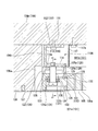
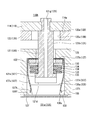
- FIG. 3 is an enlarged cross-sectional view showing a region including a stepped bolt (support member) in the vacuum processing apparatus according to the first embodiment of the present invention. It is sectional drawing which shows the heat expansion state of the edge part of the electrode frame, the slide plate, and the shower plate in the vacuum processing apparatus which concerns on 1st Embodiment of this invention. It is a flow chart which shows the cleaning method of the vacuum processing unit concerning a 1st embodiment of the present invention.
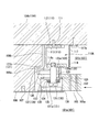
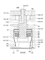
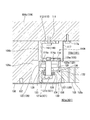
- FIG. 6 is an enlarged cross-sectional view showing another example of a region including a stepped bolt (support member) in the vacuum processing apparatus according to the first embodiment of the present invention. It is sectional drawing which shows the edge part of the electrode frame, slide plate, and shower plate in the vacuum processing apparatus which concerns on 2nd Embodiment of this invention.
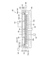
- FIG. 1 is a schematic cross-sectional view showing a vacuum processing apparatus according to this embodiment.
- reference numeral 100 is a vacuum processing apparatus.
- the vacuum processing apparatus 100 performs film formation on a substrate (substrate to be processed) S by a plasma CVD method.
- the vacuum processing apparatus 100 has a processing chamber 101 having a film forming space 101a which is a reaction chamber.
- the processing chamber 101 includes a vacuum chamber 102 (chamber), an electrode flange 104, and an insulating flange 103 sandwiched between the vacuum chamber 102 and the electrode flange 104.
- An opening is formed in the bottom portion 102a (inner bottom surface) of the vacuum chamber 102.
- a column 145 is inserted through this opening, and the column 145 is arranged in the lower portion of the vacuum chamber 102.
- a plate-shaped support portion (heater) 141 is connected to the tip of the column 145 (inside the vacuum chamber 102).
- the vacuum chamber 102 is provided with a vacuum pump (exhaust means) 148 via an exhaust pipe.
- the vacuum pump 148 reduces the pressure so that the inside of the vacuum chamber 102 is in a vacuum state.
- the column 145 is connected to an elevating mechanism (not shown) provided outside the vacuum chamber 102, and is vertically movable in the vertical direction of the substrate S.
- the vacuum chamber 102 is provided with a cleaning gas supply unit 149 via a supply pipe.
- the cleaning gas supply unit 149 is capable of ejecting a cleaning gas, which will be described later, into the film formation space 101a in order to clean the inside of the vacuum chamber 102, in particular, the deposit adhered to the film formation space 101a side.
- the opening of the supply pipe in the cleaning gas supply unit 149 is arranged near the edge of the shower plate 105.
- the electrode flange 104 has an upper wall 104a and a peripheral wall 104b.
- the electrode flange 104 is arranged such that the opening of the electrode flange 104 is located below the substrate S in the vertical direction.
- a shower plate 105 is attached to the opening of the electrode flange 104.
- a space 101b (gas introduction space) is formed between the electrode flange 104 and the shower plate 105.
- the upper wall 104 a of the electrode flange 104 faces the shower plate 105.
- a gas supply unit 142 (gas supply means) is connected to the upper wall 104a via a gas introduction port.
- the space 101b functions as a gas introduction space into which the process gas is introduced from the gas supply unit 142.
- the electrode flange 104 and the shower plate 105 are each made of a conductive material, and are made of metal such as aluminum.
- An electrode mask 107 is arranged on the surface of the shower plate 105 on the space 101b side so as to cover the peripheral portion thereof.
- the electrode mask 107 is attached to the insulating shield 106.
- a shield cover is provided around the electrode flange 104 so as to cover the electrode flange 104.
- the shield cover is not in contact with the electrode flange 104 and is arranged so as to be continuous with the peripheral portion of the vacuum chamber 102.
- An RF power source 147 (high frequency power source) provided outside the vacuum chamber 102 is connected to the electrode flange 104 via a matching box.
- the matching box is attached to the shield cover, and the vacuum chamber 102 is grounded via the shield cover.
- the electrode flange 104 and the shower plate 105 are configured as a cathode electrode.
- the shower plate 105 is formed with a plurality of gas ejection ports 105a.
- the process gas introduced into the space 101b is ejected from the gas ejection port 105a to the film formation space 101a in the vacuum chamber 102.
- the electrode flange 104 and the shower plate 105 which are supplied with power from the RF power source 147, serve as cathode electrodes, plasma is generated in the film formation space 101a, and processing such as film formation is performed.
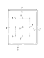
- FIG. 2 is a plan view of the shower plate 105 according to the present embodiment as viewed from above.
- the shower plate 105 is hung and supported downward from the electrode flange 104 by a rod-shaped fixed shaft 109 and a movable shaft 108.
- the fixed shaft 109 is fixedly attached to the central position of the shower plate 105 in plan view.
- the movable shaft 108 is arranged at the apex of a rectangle centered on the fixed shaft 109 and the midpoint of the four sides.
- the movable shaft 108 has a structure that moves in accordance with the thermal expansion of the shower plate 105. Specifically, the movable shaft 108 is connected to the shower plate 105 via a spherical bush provided at the lower end of the movable shaft 108. The movable shaft 108 is capable of supporting the shower plate 105 while moving in accordance with the deformation of the shower plate 105 in the horizontal direction.
- FIG. 3 is an enlarged cross-sectional view showing a region including an edge portion of the shower plate 105 according to this embodiment.
- An insulating shield 106 is circumferentially provided outside the peripheral edge of the shower plate 105 so as to be separated from the edge of the shower plate 105.
- the insulating shield 106 is attached to the peripheral wall 104b of the electrode flange 104.
- a heat expansion absorption space (gap) 106a is formed at a position inside the insulating shield 106 and a position outside the peripheral end surface of the shower plate 105.
- an electrode frame 110 and a slide plate 120 are provided around the upper edge of the shower plate 105.
- the electrode frame 110 is attached to the lower side of the peripheral wall 104b of the electrode flange 104 by a support member 111 such as a bolt.
- the electrode frame 110 is circumferentially provided inside the insulating shield 106.
- the electrode frame 110 is circumferentially provided at a position that is an outer contour of the gas introduction space 101b in plan view.
- the slide plate 120 is provided around the periphery of the shower plate 105 so as to substantially overlap the electrode frame 110 in plan view.
- the slide plate 120 is attached to the shower plate 105.
- the shower plate 105 and the electrode frame 110 are slidable.
- the edge of the shower plate 105 is suspended and supported by the electrode frame 110 by a stepped bolt 121.
- the stepped bolt 121 penetrates the shower plate 105 and the slide plate 120 from the lower side, and the tip thereof is fastened to the electrode frame 110.
- the slide plate 120 is located between the electrode frame 110 and the shower plate 105.
- the slide plate 120 can move in a direction parallel to the surface of the shower plate 105 integrally with the edge of the shower plate 105 in response to thermal deformation that occurs when the temperature of the shower plate 105 is raised or lowered.
- the electrode frame 110 moves so that the slide plate 120 slides and the slide position changes in response to thermal deformation of the shower plate 105 that occurs when the temperature of the shower plate 105 is raised or lowered.
- the electrode frame 110 and the slide plate 120 are sealing side walls of the gas introduction space 101b surrounded by the shower plate 105 and the electrode flange 104.
- the electrode frame 110 and the slide plate 120 are slidable between the slide plate 120 attached to the shower plate 105 and the electrode frame 110 attached to the electrode flange 104 corresponding to the slide plate 120. However, they remain in contact with each other.
- the electrode frame 110 and the slide plate 120 can seal the gas introduction space 101b even when they slide with each other.
- the electrode frame 110 and the slide plate 120 electrically connect the peripheral edge of the shower plate 105 and the electrode flange 104.
- the electrode frame 110 has a rectangular contour that is an outer contour that is substantially equal to the peripheral edge of the shower plate 105 in plan view.
- the electrode frame 110 also has substantially equal width dimensions around the shower plate 105.
- the electrode frame 110 is made of metal such as Hastelloy.
- the slide plate 120 has a rectangular contour which is substantially the same as the outer contour of the peripheral portion of the shower plate 105 in a plan view like the electrode frame 110.
- the slide plate 120 also has approximately equal width dimensions around the shower plate 105.
- the slide plate 120 may be made of the same material as the electrode frame 110, for example, a metal such as Hastelloy.
- the electrode frame 110 has an upper plate surface portion (fixing portion) 112, a vertical plate surface portion (wall portion) 113, and a lower plate surface portion (base portion) 114.
- the upper plate surface portion (fixed portion) 112 is fixedly attached to the lower surface of the electrode flange 104 facing the shower plate 105.
- the vertical plate surface portion (wall portion) 113 is erected from the entire periphery of the contour outer end portion of the upper plate surface portion (fixed portion) 112 toward the shower plate 105.
- the lower plate surface portion (base portion) 114 extends from the lower end of the vertical plate surface portion (wall portion) 113 substantially parallel to the upper plate surface portion (fixed portion) 112.
- the electrode frame 110 has an upper plate surface portion (fixed portion) 112, a vertical plate surface portion (wall portion) 113, and a lower plate surface portion (base portion) 114 so that the cross-sectional shape orthogonal to the contour of the shower plate 105 is U-shaped. Is formed in.
- the electrode frame 110 is formed by an upper plate surface portion (fixed portion) 112, a vertical plate surface portion (wall portion) 113, and a lower plate surface portion (base portion) 114 so as to have an internal space 110A inside the U shape. ..
- the upper plate surface portion (fixed portion) 112 is attached to the peripheral wall 104b of the electrode flange 104 by a supporting member 111 such as a bolt.
- the support member 111 penetrates the upper plate surface portion (fixed portion) 112.
- the vertical plate surface portion (wall portion) 113 is erected substantially vertically from the electrode flange 104 toward the main surface of the shower plate 105.
- the upper end of the vertical plate surface portion (wall portion) 113 is connected to the end portion of the upper plate surface portion (fixed portion) 112 on the entire outer periphery of the contour of the electrode frame 110.
- the vertical plate surface portion (wall portion) 113 is arranged inside the insulating shield 106.
- the vertical plate surface portion (wall portion) 113 faces the inner peripheral surface of the insulating shield 106.
- the outer peripheral surface of the peripheral portion of the vertical plate surface portion (wall portion) 113 is separated from the inner peripheral surface of the insulating shield 106.
- a gap 106b is formed between the outer peripheral surface of the peripheral portion of the vertical plate surface portion (wall portion) 113 and the inner peripheral surface of the insulating shield 106.
- the electrode frame 110 is attached to the electrode flange 104 and is on the low temperature side. Therefore, the dimension of thermal expansion of the electrode frame 110 expected when the temperature is raised is smaller than the dimension of thermal expansion of the shower plate 105 and the slide plate 120 expected when the temperature is raised.
- the gap 106b is set smaller than the thermal expansion absorption space 106a. That is, the distance between the outer peripheral surface of the vertical plate surface portion (wall portion) 113 and the inner peripheral surface of the insulating shield 106 is set smaller than the distance between the outer peripheral end surface of the shower plate 105 and the inner peripheral side surface of the insulating shield 106.
- a step is formed on the inner peripheral surface of the insulating shield 106 so as to correspond to the gap 106b and the heat expansion absorption space 106a. This step is formed closer to the electrode frame 110 than the slip seal surface 114a, which is the contact position between the slide plate 120 and the electrode frame 110, and the slip seal surface 120a.
- the lower end of the vertical plate surface portion (wall portion) 113 is connected to the outer peripheral side end portion of the lower plate surface portion (base portion) 114.
- the lower plate surface portion (base portion) 114 is arranged from the lower end of the vertical plate surface portion (wall portion) 113 toward the center side of the gas introduction space 101b. That is, the lower plate surface portion (base portion) 114 extends from the lower end of the vertical plate surface portion (wall portion) 113 toward the inside of the contour of the electrode frame 110. The lower plate surface portion (base portion) 114 extends parallel to the upper plate surface portion (fixed portion) 112.
- the lower plate surface portion (base portion) 114 has substantially the same width dimension over the entire circumference of the shower plate 105.
- the plate thickness of the lower plate surface portion (base portion) 114 can be set to be larger than the plate thickness of the upper plate surface portion (fixed portion) 112.
- the lower surface of the lower plate surface portion (base portion) 114 on the shower plate 105 side is a slide seal surface 114 a that is parallel to the main surface of the shower plate 105.
- the slip seal surface 114 a is in contact with the slip seal surface 120 a provided on the upper surface of the slide plate 120.
- the slip seal surface 114a is the entire lower surface of the lower plate surface portion (base portion) 114 on the shower plate 105 side.
- a stepped bolt 121 is screwed from below to the lower plate surface portion (base portion) 114.
- a plate-shaped reflector 117 is provided on the entire inner circumference of the electrode frame 110.
- the reflectors 117 are provided at four locations in parallel with the contour sides of the shower plate 105 having a rectangular contour.
- the reflector 117 is arranged close to the inner peripheral side of the electrode frame 110.
- the reflector 117 is a metal plate bent in an L shape.
- the upper end of the reflector 117 is bent toward the center of the gas introduction space 101b.
- the bent portion at the upper end of the reflector 117 is attached to the peripheral wall 104b of the electrode flange 104 with a screw 117a.
- the outside of the upper end of the reflector 117 is arranged close to the inside end of the upper plate surface portion (fixed portion) 112 of the electrode frame 110.
- the lower end of the reflector 117 is located near the inner end of the lower plate surface portion (base portion) 114 of the electrode frame 110. Therefore, the reflector 117 is arranged so as to face the opening of the internal space 110A of the electrode frame 110, which is U-shaped in a cross-sectional view, at a distance.
- the lower end of the reflector 117 and the inner end of the lower plate surface portion (base portion) 114 of the electrode frame 110 are not connected. Therefore, the gas can easily enter from the gas introduction space 101b to the internal space 110A of the electrode frame 110.
- FIG. 4 is an enlarged perspective view of a corner portion on the lower surface side of the slide plate 120 according to this embodiment.
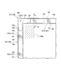
- FIG. 5 is a bottom view showing a region including a peripheral portion of the shower plate 105 in this embodiment.
- the entire upper surface of the slide plate 120 serves as a slip seal surface 120a.
- the slide plate 120 has a configuration in which a plate body parallel to the upper surface of the shower plate 105 is formed in a frame shape having a substantially equal width. As shown in FIGS. 4 and 5, the slide plate 120 corresponds to the side slide portions 122 positioned corresponding to the four sides of the shower plate 105 having a substantially rectangular contour and the four corners of the shower plate 105. And a corner slide portion 127 located therein.
- the side slide part 122 and the corner slide part 127 have the same thickness dimension as shown in FIG. Both the side slide portion 122 and the corner slide portion 127 are attached to the upper surface of the shower plate 105.
- the corner slide portions 127 are respectively combined with the end portions of the side slide portions 122 extending on two adjacent sides of the shower plate 105.
- the corner slide portion 127 is fixed to the upper surface of the shower plate 105 with a fastening screw 127a.
- the side slide 122 is attached to the upper surface of the shower plate 105 by being sandwiched between the corner slide 127 fixed to the shower plate 105 and the shower plate 105 and the electrode frame 110. Further, the side slide portion 122 is regulated in position so as not to come off even by the stepped bolt 121 penetrating the through hole 125a, as described later.
- the corner slide portion 127 is provided with two labyrinth convex portions 128, 128 that respectively project toward the combined side slide portion 122.
- the labyrinth convex portion 128 projects in the direction along the contour side of the shower plate 105.
- the two labyrinth convex portions 128 of the corner slide portion 127 project in directions orthogonal to each other.
- the labyrinth convex portion 128 is arranged at the center in the width direction of the corner slide portion 127. That is, each of the two labyrinth convex portions 128 is arranged at the central position in the width direction of the slide plate 120 facing each other.
- the side slide portion 122 is provided with two labyrinth convex portions 123 and 124 that project toward the combined corner slide portion 127.
- the labyrinth convex portion 123 and the labyrinth convex portion 124 project in the direction along the contour side of the shower plate 105.
- the labyrinth convex portion 123 and the labyrinth convex portion 124 are formed in parallel with each other.
- the labyrinth convex portion 123 and the labyrinth convex portion 124 are arranged at both outer positions in the width direction of the slide plate 120 with respect to the labyrinth convex portion 128 of the corner slide portion 127.
- the labyrinth convex portion 123 and the labyrinth convex portion 124 are set to have the same dimension in the width direction of the slide plate 120.
- the width dimensions of the labyrinth convex portion 123 and the labyrinth convex portion 124 can both be set smaller than the width dimension of the labyrinth convex portion 128.
- the labyrinth convex portion 123 and the labyrinth convex portion 128 are in contact with each other. Further, the labyrinth convex portion 124 and the labyrinth convex portion 128 are in contact with each other.
- the inner side surface of the labyrinth convex portion 123 is a slip seal surface 123a
- the outer side surface of the labyrinth convex portion 128 is a slip seal surface 128a.
- the slip seal surface 123a and the slip seal surface 128a are in contact with each other.
- the outer side surface of the labyrinth convex portion 124 serves as a slip seal surface 124b
- the inner side surface of the labyrinth convex portion 128 serves as a slip seal surface 128b.
- the slip seal surface 124b and the slip seal surface 128b are in contact with each other.
- the inner side and the outer side mean positions inward and outward with respect to the gas introduction space 101b, that is, positions in the radial direction from the center in the plane of the shower plate 105.
- the slip seal surface 128a and the slip seal surface 128b are formed parallel to each other.
- the slip seal surface 123a and the slip seal surface 124b facing each other are formed in parallel to each other.
- the slip seal surface 128a, the slip seal surface 128b, the slip seal surface 123a, and the slip seal surface 124b are all formed in a direction parallel to the contour side of the shower plate 105.
- the slip seal surface 128a, the slip seal surface 128b, the slip seal surface 123a, and the slip seal surface 124b are all formed in the vertical direction.
- the upper ends of the slip seal surface 128a, the slip seal surface 128b, the slip seal surface 123a, and the slip seal surface 124b are in contact with the electrode frame 110.
- the lower ends of the sliding seal surface 128a, the sliding seal surface 128b, the sliding seal surface 123a, and the sliding seal surface 124b are in contact with the shower plate 105.
- the labyrinth convex portion 123 of the side slide portion 122, the labyrinth convex portion 128 of the corner slide portion 127, and the labyrinth convex portion 124 of the side slide portion 122 are arranged in the contour direction of the gas introduction space 101b. That is, the labyrinth convex portion 123, the labyrinth convex portion 128, and the labyrinth convex portion 124 are alternately arranged in the contour direction of the gas introduction space 101b so as to be multi-tiered from the inside to the outside of the gas introduction space 101b. ..
- the labyrinth convex portion 124 and the labyrinth convex portion 128 maintain the contact state. .. Since the slip seal surface 124b and the slip seal surface 128b are not separated from each other in this manner, the seal at this portion is maintained.
- the labyrinth convex portion 128 and the labyrinth convex portion 123 maintain the contact state. .. Since the slip seal surface 128a and the slip seal surface 123a are not separated from each other in this manner, the seal at this portion is maintained.
- the labyrinth convex portions 128 of the corner slide portion 127 slide while being sandwiched between the labyrinth convex portions 123 and the labyrinth convex portions 124 of the side slide portions 122 located on both sides thereof.
- the slip seal surface 124b and the slip seal surface 128b are not separated from each other.
- the slip seal surface 128a and the slip seal surface 123a are not separated from each other.
- the sealed state at the side wall portion of the gas introduction space 101b can be maintained regardless of the temperature state.
- the slide plate 120 is provided with a recessed groove 125 in a portion contacting the shower plate 105, that is, in the lower surface of the slide plate 120.
- the concave groove 125 is formed such that the leg portion 126 abutting the shower plate 105 is located on the entire circumference of the side slide portion 122.
- the depth dimension of the groove 125 can be arbitrarily set as long as it is smaller than the thickness dimension of the slide plate 120 and the strength of the slide plate 120 is not reduced.
- the width dimension of the leg portion 126, that is, the width direction dimension of the slide plate 120 is preferably as small as possible as long as the strength of the slide plate 120 is not reduced.
- the concave groove 125 is formed in the side slide portion 122.
- the concave groove may be formed in the corner slide portion 127.
- a concave groove may be formed so that the leg portion that abuts the shower plate 105 is located all around the corner slide portion 127. Further, in this case, in the corner slide portion 127, the labyrinth convex portion 128 can also be formed with a concave groove.
- a through hole 125 a is provided inside the concave groove 125.
- the through hole 125a penetrates the slide plate 120.
- a plurality of through holes 125a are provided in the direction in which the side slide portion 122 extends.
- the plurality of through holes 125a are arranged apart from each other. It is also possible to form only the through hole 125a in the slide plate 120 and not provide the concave groove 125.
- the stepped bolt 121 penetrates through the through hole 125a.
- the diameter of the through hole 125a is set larger than the diameter of the stepped bolt 121.
- the contour shape of the through hole 125a corresponds to an elongated hole 131 described later.
- the shape in which the through hole 125a corresponds to the elongated hole 131 means that the shaft portion 121b of the stepped bolt 121 can slide without trouble in response to thermal deformation that occurs when the temperature of the shower plate 105 is raised or lowered, as described later. It means that it has a simple shape. That is, it means that the through hole 125a has a shape that does not affect the relative movement of the stepped bolt 121 inside the elongated hole 131.
- the diameter of the through hole 125a is larger than the long axis of the long hole 131. That is, when the through hole 125a is formed to be larger than the elongated hole 131 in plan view, it does not come into contact with the shaft portion 121b of the stepped bolt 121 that relatively moves inside the elongated hole 131. Further, the outline shape of the through hole 125a is not particularly limited as long as the above dimensions are satisfied.
- FIG. 6 is a cross-sectional view showing a region including the hanging groove 130 and the elongated hole 131 of the shower plate 105 in the present embodiment, and is an enlarged arrow cross-sectional view shown in FIG. As shown in FIGS. 3, 5, and 6, the lower surface of the shower plate 105 is provided with a hanging groove 130 at the peripheral edge of the shower plate 105.
- a plurality of suspension grooves 130 are provided at the peripheral edge of the shower plate 105 at predetermined intervals.
- An elongated hole 131 that penetrates the shower plate 105 in the thickness direction is provided inside the hanging groove 130.
- the hanging groove 130 is formed as a similar shape in which the elongated hole 131 is enlarged.
- the shaft portion 121 b of the stepped bolt 121 penetrates the long hole 131 and is fixed to the electrode frame 110.
- the elongated hole 131 is formed long in the direction of thermal deformation of the shower plate 105 so that the shaft portion 121b of the stepped bolt 121 can slide in response to thermal deformation of the shower plate 105 when the temperature of the shower plate 105 is increased or decreased.
- the long hole 131 has a long axis parallel to a straight line radially drawn from the fixed shaft 109 which is the central position when the shower plate 105 is viewed in plan. Therefore, the elongated hole 131 is an ellipse (rounded rectangle) having major axes in different tilt directions depending on the position where the elongated hole 131 is arranged.
- the long hole 131 has an opening dimension in the long axis direction set to be longer than the distance over which the shaft portion 121b of the stepped bolt 121 relatively moves, corresponding to the thermal deformation that occurs when the shower plate 105 is heated and lowered. Therefore, the dimension of the long hole 131 in the long axis direction needs to be appropriately changed depending on the dimension of the shower plate 105 and the coefficient of thermal expansion defined by the material.
- the opening dimension of the long hole 131 in the minor axis direction may be slightly larger than the outer diameter dimension of the shaft portion 121b of the stepped bolt 121.
- a long slide member (long washer) 132 is arranged in the opening of the long hole 131 on the side of the hanging groove 130.
- the shaft portion 121 b of the stepped bolt (support member) 121 penetrates the long slide member 132.
- the long slide member 132 has a contour shape that is the same as or slightly smaller than the hanging groove 130.
- the long slide member 132 has an opening shape that is similar to or slightly smaller than the long hole 131.
- the opening diameter dimension of the long slide member 132 in the minor axis direction is set to be the same as or slightly smaller than the opening diameter dimension of the elongated hole 131 in the minor axis direction.
- the opening diameter dimension of the long slide member 132 in the long axis direction is set to be the same as or slightly smaller than the opening diameter dimension of the long hole 131 in the long axis direction.
- a bolt head 121 a of the stepped bolt 121 is located below the long slide member 132. Between the long slide member 132 and the bolt head 121a, a slide member (washer) 133 and disc springs 134 and 135 are stacked and arranged from above. The shaft portion 121b of the stepped bolt 121 penetrates through the slide member 133 and the disc springs 134 and 135.
- the opening diameter dimension of the long slide member 132 in the minor axis direction is set smaller than the outer diameter dimension of the bolt head 121a of the stepped bolt 121.
- the opening diameter dimension of the long slide member 132 in the short axis direction is set smaller than the outer diameter dimension of the slide member 133.
- the outer diameter dimension of the slide member 133 is set to be the same as or slightly larger than the outer diameter dimension of the bolt head 121a. Further, the outer diameter dimension of the slide member 133 is set to be larger than the opening diameter dimension of the long slide member 132 in the short axis direction.
- the inner diameters of the slide member 133 and the disc springs 134 and 135 are set to be the same as or slightly larger than the outer diameters of the shaft portion 121b of the stepped bolt 121.
- the slide member 133 and the disc springs 134 and 135 follow the slide of the stepped bolt 121 which is slidable inside the suspension groove 130.
- the long slide member 132 and the slide member 133 are slidably in contact with each other.
- the stepped bolt 121 moves relative to the thermal deformation that occurs when the shower plate 105 is heated and lowered. At this time, the shaft portion 121b slides in the longitudinal direction of the elongated hole 131 inside the suspending groove 130. Following this slide movement, the slide member 133 also slides in the longitudinal direction of the elongated hole 131 inside the suspending groove 130.
- the slide member 133 slides with the long slide member 132 located below the periphery of the long hole 131 inside the hanging groove 130.
- the relationship among the opening dimension of the long hole 131 in the short axis direction, the opening dimension of the long slide member 132 in the short axis direction, the outer diameter dimension of the slide member 133, and the outer diameter dimension of the bolt head 121a is as described above in order from the top. Is set.
- the long slide member 132 can be regulated so as not to move to the concave groove 125 side from the opening of the long hole 131.
- the slide member 133 can be regulated so as not to move from the opening of the long slide member 132 to the concave groove 125 side.
- the bolt head 121a can be regulated so as not to move in the vertical direction with respect to the slide member 133.
- the long slide member 132 and the slide member 133 regulate the position of the bolt head 121a so as not to move to the electrode frame 110 side. That is, the bolt head 121a of the stepped bolt 121 can be restricted so as not to come out toward the concave groove 125 side.
- the long slide member 132 and the slide member 133 are regulated so that the position of the bolt head 121a in the axial direction of the stepped bolt 121 becomes constant.
- the long slide member 132 and the slide member 133 slide while maintaining the suspended state of the shower plate 105 by the stepped bolt 121. Accordingly, the step height 121 of the shower plate 105 can be maintained and the stepped bolt 121 can slide inside the hanging groove 130.
- the long slide member 132 and the slide member 133 can be made of the same material as the slide plate 120. Specifically, the long slide member 132 and the slide member 133 can be made of a metal such as Hastelloy.
- the disc springs 134 and 135 are attached so as to urge the bolt head 121a of the stepped bolt 121 downward. As shown in FIG. 6, the disc springs 134 and 135 may be plural in number.
- the disc springs 134 and 135 correspond to the thermal deformation of the shower plate 105 when the temperature of the shower plate 105 is raised or lowered, and follow the slide of the shaft portion 121b of the stepped bolt 121, inside the hanging groove 130. It is supposed to be movable. At this time, the biased state of the disc springs 134 and 135 against the bolt head 121a and the slide member 133 is maintained.
- the disc springs 134 and 135 may be provided in a plural number, and the number thereof is not limited.
- the slide member 133 and the disc springs 134 and 135 can be made of an elastic material such as Inconel.
- a lid 136 is provided at the lower opening position of the hanging groove 130.
- the lid 136 closes the lower opening of the hanging groove 130. That is, the lid 136 closes the opening of the elongated hole 131.
- the lid portion 136 has an insertion portion 136 a inserted inside the opening of the hanging groove 130, a flange portion 136 f provided around the insertion portion 136 a, and the lid portion 136 so as not to come off from the hanging groove 130. And a biasing portion 137 that biases the lid portion 136.
- the planar contour shape of the insertion portion 136a is similar to the opening of the suspension groove 130.
- the insertion portion 136 a has a contour shape that is slightly smaller than the opening of the hanging groove 130.
- the insertion portion 136a has a configuration in which a plate body that closes the opening of the hanging groove 130 and a plate-like shape along the inner wall of the hanging groove 130 are connected.
- an inclined surface 136c that is inclined toward the inner wall of the hanging groove 130 is formed on the outer periphery facing the inner wall of the hanging groove 130 along the direction away from the flange portion 136f. ..
- the insertion portion 136a is enlarged in diameter in a direction away from the flange portion 136f by the inclined surface 136c.
- the insertion portion 136a may be a bulk-shaped member that closes the opening of the suspension groove 130.
- the flange portion 136f contacts the lower surface of the shower plate 105 around the opening of the suspension groove 130.
- the contour shape of the flange portion 136f is similar to the opening of the hanging groove 130.
- the flange portion 136f has a contour shape slightly larger than the opening of the hanging groove 130.
- the lid 136 is attached so that the flange portion 136f contacts the lower surface of the shower plate 105 over the entire circumference of the opening of the hanging groove 130.
- the insertion portion 136a and the flange portion 136f are formed such that when the lid 136 is attached so as to close the hanging groove 130, the surface of the lid 136 is a plane parallel to the lower surface of the shower plate 105.
- the biasing portion 137 is an elastic member that biases and tightens the insertion portion 136a when the lid portion 136 is attached so as to close the suspension groove 130.
- the biasing portion 137 is, for example, a leaf spring.
- the biasing portion 137 has a base portion 137b located on the innermost portion of the hanging groove 130, that is, on the long hole 131 side of the long slide member 132.
- the base portion 137b is sandwiched between the innermost portion of the hanging groove 130 and the long slide member 132, and is fixed inside the hanging groove 130.
- the base portion 137b has an opening of a size corresponding to the elongated hole 131 or has a planar contour shape that does not close the elongated hole 131.
- the base portion 137b is connected to two elastic portions 137s that are bent from both ends of the base portion 137b and extend along the inner wall of the hanging groove 130.
- the elastic portion 137s is arranged such that the plate surface of the elastic portion 137s is substantially parallel to the long axis direction of the elongated hole 131.
- the elastic portions 137s are provided one by one on both sides of the elongated hole 131 in the short axis direction.
- the two elastic portions 137s are both inclined toward the center side of the hanging groove 130 from the base portion 137b side toward the opening side of the hanging groove 130.
- the tip 137t of the elastic portion 137s on the opening side of the hanging groove 130 is inclined so as to approach the opposite side, that is, the side wall of the hanging groove 130. That is, the two elastic portions 137s gradually decrease in distance in the direction in which the two elastic portions 137s face each other from the base portion 137b side toward the tip 137t, and are separated on the tip 137t side.
- the distance between the two tips 137t that have once expanded gradually increases along the inclined surface 136c of the insertion portion 136a due to the elasticity of the elastic portion 137s. Decrease.
- the elastic portion 137s urges the inclined surface 136c of the insertion portion 136a to be sandwiched.
- the insertion of the insertion portion 136a in the depth direction of the hanging groove 130 ends when the flange portion 136f contacts the lower surface of the shower plate 105 over the entire circumference of the opening of the hanging groove 130. As a result, the opening of the hanging groove 130 is closed by the lid 136.
- the lid 136 prevents the gas from entering the inside of the hanging groove 130 from the film forming space 101a side.
- the two tips 137t of the biasing portion 137 are in contact with the inclined surface 136c of the insertion portion 136a. Both of the two tips 137t are biased in a direction of sandwiching the inclined surface 136c of the insertion portion 136a.
- the two elastic portions 137s sandwich the inclined surface 136c of the insertion portion 136a, so that the lid portion 136 can be attached so as not to come off the hanging groove 130. Therefore, gas can be prevented from entering the inside of the hanging groove 130 from the film formation space 101a side.
- the tip of the shaft portion 121b is screwed onto the lower plate surface portion (base portion) 114 from below.
- the stepped bolt 121 penetrates the lower plate surface portion (base portion) 114.
- the shaft portion 121b of the stepped bolt 121 has a U-shape of the electrode frame 110 formed by the upper plate surface portion (fixed portion) 112, the vertical plate surface portion (wall portion) 113, and the lower plate surface portion (base portion) 114. Is projected into the internal space 110A.
- the internal space 110A of the electrode frame 110 is in communication with the gas introduction space 101b near the lower end of the reflector 117.
- the lower end of the bolt head 121a is located inside the suspension groove 130.
- the bolt head 121a is provided with a recess 121d for turning the stepped bolt 121 with a tool.
- a gas hole 121g is formed in the shaft portion 121b of the stepped bolt 121 and the bolt head 121a in the axial direction of the stepped bolt 121.
- the gas hole 121g penetrates from the tip of the shaft 121b to the lower end of the bolt head 121a.
- the gas hole 121g is formed coaxially with the central axis of the shaft portion 121b.
- the gas hole 121g opens in the bottom surface of the recess 121d in the bolt head 121a.
- the stepped bolt 121 penetrates the lower plate surface portion (base portion) 114 of the electrode frame 110, the through hole 125 a and the concave groove 125 of the slide plate 120, and the elongated hole 131 of the shower plate 105.
- the gas hole 121g communicates with the internal space 110A in the vertical direction between the slip seal surface 114a of the lower plate surface portion (base portion) 114 and the slip seal surface 120a of the slide plate 120.
- the inside of the hanging groove 130 can maintain the communication state with the gas introduction space 101b communicating with the internal space 110A.
- the inside of the elongated hole 131 communicating with the inside of the suspension groove 130 communicates with the gas introduction space 101b.
- the inside of the concave groove 125 that communicates with the elongated hole 131 communicates with the gas introduction space 101b.
- the inside of the through hole 125a that communicates with the concave groove 125 communicates with the gas introduction space 101b.
- the suspension groove 130, the elongated hole 131, the concave groove 125, and the through hole 125a can all be maintained in a state of communicating with the gas introduction space 101b. Further, even in the vicinity of the slip seal surface 114a exposed at the opening of the through hole 125a, the state of communicating with the gas introduction space 101b is maintained.
- the stepped bolt 121 is provided with the gas hole 121g, so that the gas can be supplied from the gas introduction space 101b to the inside of the hanging groove 130 communicating with the gas.
- the gas can be supplied from the gas introduction space 101b to the inside of the elongated hole 131, the inside of the concave groove 125, the inside of the through hole 125a, and the vicinity of the slip seal surface 114a exposed at the opening of the through hole 125a.
- the film formation space 101a is cleaned at the end of the film formation process. Parts that may be exposed to the cleaning gas during cleaning are given a corrosion resistant surface treatment.
- parts that are subjected to corrosion resistant surface treatment include parts made of Hastelloy, Inconel, aluminum, etc.
- the shower plate 105, the lid 136, the electrode frame 110, and the slide plate 120 are examples of parts made of Hastelloy, Inconel, aluminum, etc.
- the corrosion resistant surface treatment can be applied to the entire surface of these parts, or only to areas that may be exposed to the cleaning gas.
- Y 2 O 3 treatment is performed as a corrosion-resistant surface treatment. This is a process for forming a thin film.
- the thin film formation of Y 2 O 3 that is, the yttria coat is performed by a CVD process.
- the film thickness of Y 2 O 3 can be set to about 50 to 1000 nm, preferably about 100 nm.
- the yttria-coated part is subjected to electrolytic polishing or aluminum surface diffusion treatment prior to the yttria coating to further improve the corrosion resistance.
- the parts to which the yttria coat is applied are the parts made of nickel alloy such as Inconel or Hastelloy.
- the corrosion resistance in the portion exposed to the cleaning gas can be improved and the generation of particles can be prevented.
- the yttria coat is highly effective in improving corrosion resistance.
- the yttria coat can exert an extremely high effect of suppressing the generation of particles due to the corrosion of the cleaning gas.
- FIG. 7 is an enlarged cross-sectional view of the vicinity of the edge of the shower plate 105 in the thermally expanded state of the present embodiment.
- the shower plate 105 is thermally expanded (thermally deformed) because it is heated.
- the shower plate 105 expands outward in the in-plane direction around the fixed shaft 109.
- the peripheral portion of the shower plate 105 that has been thermally expanded does not contact the insulating shield 106 by expanding to the thermal expansion absorption space 106a. Therefore, the expansion of the shower plate 105 is absorbed so as not to give stress to the electrode flange 104, the electrode frame 110, the insulating shield 106 and the like. At this time, the movable shaft 108 can support the deformed shower plate 105 by the spherical bush at the lower end.
- the slide plate 120 fixed to the peripheral portion of the thermally expanded shower plate 105 moves as a unit toward the outer periphery of the shower plate 105.
- the peripheral portion of the shower plate 105 and the slide plate 120 also move so as to narrow the heat expansion absorption space 106a, as shown in FIG. Since the slide plate 120 does not contact the insulating shield 106, the movement of the slide plate 120 is absorbed so as not to give stress to the electrode flange 104, the electrode frame 110, the insulating shield 106 and the like.
- the slide plate 120 moves together with the edge of the thermally deformed shower plate 105.
- the electrode frame 110 is fixed to the electrode flange 104, the relative position with respect to the electrode flange 104 and the insulating shield 106 does not change so much.
- the electrode frame 110 is not deformed, and the sliding seal surface 114a of the electrode frame 110 and the sliding seal surface 120a of the slide plate 120 slide, and the shower plate 105 is in a heat expansion state while maintaining the sealing state. Become.
- the stepped bolt 121 is fixed to the electrode frame 110. Therefore, the relative position of the stepped bolt 121 with respect to the electrode flange 104 and the insulating shield 106 does not change so much.
- the elongated hole 131 and the hanging groove 130 also move toward the outer periphery of the shower plate 105.
- the stepped bolt 121 relatively moves in the long axis direction of the long hole 131.
- the long axis direction of the long hole 131 coincides with the thermal deformation direction that occurs when the temperature of the shower plate 105 is increased or decreased. Therefore, the shaft portion 121b of the stepped bolt 121 can slide inside the elongated hole 131 in response to thermal deformation that occurs when the temperature of the shower plate 105 is raised or lowered. Therefore, the movement of the stepped bolt 121 is absorbed so as not to give stress to the shower plate 105 and the stepped bolt 121 located near the elongated hole 131.
- the through hole 125 a of the slide plate 120 also moves toward the outer periphery of the shower plate 105.
- the stepped bolt 121 moves relative to the through hole 125a.
- the shaft portion 121b of the stepped bolt 121 can slide inside the through hole 125a in response to thermal deformation that occurs when the shower plate 105 is heated or cooled. is there. Therefore, the movement of the stepped bolt 121 is absorbed so as not to give stress to the slide plate 120 and the stepped bolt 121 located in the vicinity of the through hole 125a.
- the suspension support of the shower plate 105 by the stepped bolt 121 with respect to the electrode frame 110 is maintained.
- the gas hole 121g of the stepped bolt 121 can maintain the communication state between the U-shaped internal space 110A and the inside of the hanging groove 130.
- the opening of the hanging groove 130 is closed by the lid 136, it is possible to prevent gas from flowing into the hanging groove 130.
- the sliding seal surface 114a of the lower plate surface portion (base portion) 114 of the electrode frame 110 and the sliding seal surface 120a of the slide plate 120 slide in the thermal expansion direction of the shower plate 105. Therefore, even during thermal expansion, the contact state is maintained without being deformed, so that the seal state and the load supporting state of the shower plate 105 can be maintained.
- the electrode frame 110 and the slide plate 120 are made of the same material, Hastelloy, it is possible to suppress the generation of particles due to the scraping of the members. Therefore, it is possible to prevent the film thickness characteristics of the vacuum processing apparatus 100 from being deteriorated.
- the corner slide portion 127 that slidably seals the end portions of the side slide portions 122 of the slide plate 120. Is provided.
- the side slide portion 122 fixed to the peripheral portion of the shower plate 105 and the corner slide portion 127 are separated in a linear direction along the contour side of the shower plate 105.
- the labyrinth convex portion 123 and the labyrinth convex portion 124 of the side slide portion 122 and the labyrinth convex portion 128 of the corner slide portion 127 are separated from each other.
- the slip seal surface 123a and the slip seal surface 128a slide in the direction along the contour line of the shower plate 105. Further, the slip seal surface 124b and the slip seal surface 128b slide in the direction along the contour line of the shower plate 105. Accordingly, the side slide portion 122 and the corner slide portion 127 can be separated from each other while maintaining the sealed state.
- the side slide part 122 and the corner slide part 127 having the labyrinth structure as described above can prevent gas leakage in the shower plate 105 and maintain the sealed state of the gas introduction space 101b.
- FIG. 8 is a flowchart showing a cleaning method of the vacuum processing apparatus according to this embodiment.
- the vacuum processing apparatus cleaning method according to the present embodiment includes a film forming step S01, a cleaning preparation step S02, an Ar gas filling step (purge step) S03, and an Ar gas sealing step (purge gas sealing). Stop step) S04.
- the cleaning method of the vacuum processing apparatus according to the present embodiment has a cleaning gas supply step (cleaning step) S05, a cleaning gas discharge step S06, and a confirmation step S07.
- a film is formed on the processing surface of the substrate S using the vacuum processing apparatus 100.
- the pressure inside the vacuum chamber 102 is reduced using the vacuum pump 148.
- the substrate S is loaded from the outside of the vacuum chamber 102 toward the film formation space 101a with the inside of the vacuum chamber 102 maintained at a vacuum.
- the substrate S is placed on the support portion (heater) 141.
- the support 145 is pushed upward, and the substrate S placed on the support (heater) 141 also moves upward.
- the distance between the shower plate 105 and the substrate S is determined as desired so as to be the distance required for proper film formation, and this distance is maintained.
- the process gas is introduced from the gas supply unit 142 into the gas introduction space 101b via the gas introduction pipe and the gas introduction port. Then, the process gas is ejected from the gas ejection port 105a of the shower plate 105 into the film formation space 101a.
- the RF power source 147 is activated to apply high frequency power to the electrode flange 104. Then, a high-frequency current flows from the surface of the electrode flange 104 along the surface of the shower plate 105, and a discharge is generated between the shower plate 105 and the support portion (heater) 141. Then, plasma is generated between the shower plate 105 and the processing surface of the substrate S.
- the process gas is decomposed in the plasma thus generated, a process gas in a plasma state is obtained, a vapor phase growth reaction occurs on the processing surface of the substrate S, and a thin film is formed on the processing surface.
- the shower plate 105 thermally expands (thermally deforms). At this time, the electrode frame 110 and the slide plate 120 maintain the sealed state. As a result, the amount of gas leaking from the gas introduction space 101b to the film formation space 101a through a portion other than the gas ejection ports 105a is reduced.
- the shower plate 105 is thermally contracted (thermally deformed).
- the electrode frame 110 and the slide plate 120 maintain the sealed state, thereby reducing the gas leaking from the gas introduction space 101b to the film formation space 101a through the portions other than the gas ejection ports 105a.
- there is no component that is forcibly deformed by the thermal deformation of the shower plate 105 it is possible to extend the life of the component.
- the end of the film forming step S01 means that the film formation has been performed a predetermined number of times, the parts exposed to the film forming space 101a such as the shower plate 105, or the parts contacted with the process gas in other parts have a predetermined value or more. It means the case where the adhered substance adheres. Further, the cumulative number of times of film formation and the cumulative time of film formation are set in advance as the timing for performing the cleaning so as to prevent the generation of particles that affect the film formation characteristics.
- the inside of the vacuum chamber 102 is exhausted using the vacuum pump 148. As a result, the process gas is removed from the film forming space 101a.
- Ar gas as a purge gas is filled into the gas introduction space 101b before cleaning.
- the purge gas is not limited to Ar gas as long as it has low reactivity.
- Ar gas is introduced from the gas supply unit 142 into the gas introduction space 101b via the gas introduction pipe and the gas introduction port.
- the inside of the vacuum chamber 102 may be evacuated by using the vacuum pump 148.
- Ar gas sealing step purge gas sealing step S04 shown in FIG. 8
- Ar gas is filled into the suspending groove 130 to prevent the intrusion of the cleaning gas.
- the suspension groove 130 is filled with Ar gas introduced into the gas introduction space 101b in the Ar gas filling step (purging step) S03.
- the inside of the vacuum chamber 102 may be evacuated using the vacuum pump 148.
- Ar gas is filled from the gas introduction space 101b into the suspension groove 130 through the U-shaped internal space 110A of the electrode frame 110 and the gas hole 121g of the stepped bolt 121. Furthermore, in the Ar gas sealing step (purge gas sealing step) S04, the elongated holes 131, the concave groove 125, and the through hole 125a are filled with the Ar gas introduced into the suspending groove 130.
- each of the gas introducing space 101b, the hanging groove 130, the elongated hole 131, the concave groove 125, and the through hole 125a is sealed with Ar gas and maintained as an Ar gas atmosphere.
- the cleaning gas is introduced into the film formation space 101a through the cleaning gas supply section 149.
- the inside of the vacuum chamber 102 is evacuated using the vacuum pump 148.
- the gas amount (flow velocity/flow rate) of the cleaning gas introduced into the film formation space 101a is set to be smaller than that of the Ar gas supplied into the gas introduction space 101b.
- the inside of the vacuum chamber 102 may be evacuated by using the vacuum pump 148.
- the cleaning gas may be NF 3 (nitrogen trifluoride), and cleans the inside of the vacuum chamber 102 with F radicals generated by the cleaning gas supply unit 149.
- NF 3 nitrogen trifluoride
- CF 4 and F 2 can also be used as the cleaning gas.
- the cleaning gas supplied from the cleaning gas supply unit 149 is ejected from the opening of the supply pipe arranged near the edge of the shower plate 105. As a result, cleaning is performed to remove deposits in the film formation space 101a. Since the cleaning gas is ejected near the edge of the shower plate 105, it is possible to sufficiently perform cleaning near the edge of the shower plate 105 with a large amount of deposits.
- the degree of exposure to the cleaning gas becomes high. That is, the vicinity of the edge of the shower plate 105 is exposed to the high-concentration cleaning gas, and the exposure time to the cleaning gas becomes long. Therefore, near the edge of the shower plate 105, the degree of corrosion caused by the cleaning gas also increases.
- the cleaning gas does not enter. Furthermore, since the hanging groove 130 is filled with Ar gas in the Ar gas sealing step (purge gas sealing step) S04, the cleaning gas does not enter.
- the stepped bolt 121, the long slide member 132, the slide member 133, and the disc springs 134 and 135 inside the suspension groove 130 are not exposed to the cleaning gas.
- the supply of the cleaning gas from the cleaning gas supply unit 149 to the film formation space 101a is stopped.
- the vacuum chamber 102 is evacuated using the vacuum pump 148. At this time, Ar gas may be continuously supplied to the gas introduction space 101b.
- a confirmation step S07 shown in FIG. 8 it is confirmed whether the adhered substances are sufficiently removed in the vacuum chamber 102.
- another film forming step S01 is performed, or a new film is formed or the operation of the apparatus is stopped. If the removal of the adhered substances is not completed, the process returns to the Ar gas filling step (purging step) S03, and the cleaning is performed again.
- the suspension groove 130 has its opening previously closed by the lid 136, and the Ar gas filling step (purge step) S03 and the Ar gas sealing step (purge gas). Sealing step) S04 is used to seal with Ar gas.
- the Ar gas filling step (purge step) S03 and the Ar gas sealing step (purge gas). Sealing step) S04 is used to seal with Ar gas.
- the stepped bolt 121 penetrates from the tip of the shaft portion 121b to the lower end of the bolt head 121a and has the gas hole 121g coaxial with the central axis of the shaft portion 121b.
- gas holes having other shapes.
- the stepped bolt 121 can be configured to have a gas hole 121g1 that communicates with the groove 125 of the slide plate 120 from the tip of the shaft portion 121b. Even with the configuration having the gas hole 121g1 of this shape, gas can be supplied from the gas introduction space 101b into the inside of the hanging groove 130 that is in communication.
- FIG. 10 is an enlarged cross-sectional view of a region including the edge portion of the shower plate 105 according to this embodiment.
- the present embodiment is different from the above-described first embodiment in that it is related to the position where the gas holes are formed, and other configurations corresponding to those of the above-described first embodiment are denoted by the same reference numerals and their description is omitted. Is omitted.
- gas holes 114g are formed in the lower plate surface portion (base portion) 114.
- the gas hole 114g vertically penetrates the lower plate surface portion (base portion) 114.
- the gas holes 114g are opened in the U-shaped internal space 110A of the electrode frame 110 in the lower plate surface portion (base portion) 114.
- the gas hole 114g is opened in the slip seal surface 114a exposed in the through hole 125a in the lower plate surface portion (base portion) 114.
- the opening position of the gas hole 114g in the slip seal surface 114a is a position that is not closed when the electrode frame 110 and the slide plate 120 slide and move.
- the gas hole 114g can communicate the upper and lower sides of the slide seal surface 114a of the lower plate surface portion (base portion) 114 and the slide seal surface 120a of the slide plate 120.
- the communication state between the U-shaped internal space 110A and the inside of the through hole 125a can be maintained. Therefore, the concave groove 125, the elongated hole 131, and the suspension groove 130 that communicate with the through hole 125a can all be maintained in the state of communicating with the gas introduction space 101b. Further, the space in the vicinity of the slip seal surface 114a exposed at the opening of the through hole 125a also maintains the state of being in communication with the gas introduction space 101b.
- the gas hole 121g may be formed in the stepped bolt 121, or a dense stepped bolt 121 without the gas hole 121g may be used.
- a dense stepped bolt 121 without the gas hole 121g may be used.
- the cleaning gas is NF 3 (nitrogen trifluoride), and the F radicals generated by the cleaning gas supply unit 149. Cleaning was performed. At the same time, the inside of the vacuum chamber 102 was evacuated using the vacuum pump 148.
- the Ar gas filling step (purge step) S03 and the Ar gas sealing step (purge gas sealing step) S04 the presence or absence of Ar sealing for supplying and filling Ar gas as a purge gas to the hanging groove 130 is switched. It was
- cleaning was performed by changing the materials of the slide plate 120 and the stepped bolt 121 and the type of surface treatment. Further, the presence or absence of Ar sealing was switched depending on the presence or absence of the gas hole 121g of the stepped bolt 121.
- the degree of corrosion was verified by repeating the cleaning 100 times by laminating the laminated film of a-Si/SiO/SiN three times at the temperature of the supporting portion (heater) 141 of 450°C.
- a plasma processing apparatus that performs a surface treatment of a substrate such as film formation, particularly plasma CVD, or etching as a treatment using plasma.
- Vacuum processing apparatus 101... Processing chamber 101a... Film forming space 101b... Space (gas introduction space) 102... Vacuum chamber 103... Insulation flange 104... Electrode flange 104a... Upper wall (electrode flange) 104b... peripheral wall (electrode flange) 105... Shower plate 105a... Gas ejection port 106... Insulation shield 106a... Thermal expansion absorption space (gap) 106b... Gap 108... Movable shaft 109... Fixed shaft 110... Electrode frame 110A... Internal space 111... Support member 112... Upper plate surface part (fixed part) 112a... Notch 113... Vertical plate surface portion (wall portion) 114...
Landscapes
- Chemical & Material Sciences (AREA)
- Engineering & Computer Science (AREA)
- Plasma & Fusion (AREA)
- Physics & Mathematics (AREA)
- Analytical Chemistry (AREA)
- General Chemical & Material Sciences (AREA)
- Chemical Kinetics & Catalysis (AREA)
- Materials Engineering (AREA)
- Mechanical Engineering (AREA)
- Metallurgy (AREA)
- Organic Chemistry (AREA)
- Public Health (AREA)
- Epidemiology (AREA)
- Health & Medical Sciences (AREA)
- Inorganic Chemistry (AREA)
- Drying Of Semiconductors (AREA)
- Chemical Vapour Deposition (AREA)
Abstract
Description
本願は、2019年1月7日に日本に出願された特願2019-000529号に基づき優先権を主張し、その内容をここに援用する。
電極フランジには、高周波電源が接続されている。電極フランジおよびシャワープレートは、カソード電極として機能する。
特許文献1、2には、シャワープレートの周囲が、電極フランジに直接接続された構成が記載されている。
しかしながら、特許文献3の技術では、シールが不十分であった。
この場合、電極フランジに対するシャワープレートの支持を良好に維持する構成を見出した。
このような腐食に起因するパーティクル発生を解決するためには、例えば、シャワープレートおよびシャワープレートの付近に位置する部品を早めに交換する必要がある。
1.クリーニングガスによる腐食発生の防止を図ること。
2.シャワープレートまわりからのガス漏れを防止するガスシールの向上を図ること。
3.部品の長寿命化を図ること。
本発明の真空処理装置は、前記ガス穴が、前記長穴を貫通する前記支持部材を軸線方向に貫通して形成されていることができる。
本発明の真空処理装置は、前記長穴の開口を閉塞する蓋部を備え、前記蓋部は、前記長穴の開口の閉塞時に、前記長穴に対して前記蓋部が外れないように付勢する付勢部を有することが可能である。
本発明の真空処理装置においては、前記処理室をクリーニングする際に、クリーニングガスに暴露される部分には、耐腐食表面処理が施されてもよい。
また、本発明の真空処理装置のクリーニング方法は、上記のいずれかに記載された真空処理装置のクリーニング方法であって、前記シャワープレートと前記電極フランジと前記電極枠と前記スライドプレートとで囲まれる空間にパージガスを供給し(パージ工程)、前記ガス穴を介して前記長穴にパージガスを供給し(パージガス封止工程)、前記処理室にクリーニングガスを供給し(クリーニング工程)、前記パージガスの供給の後に(パージガス封止工程の後に)、前記処理室に前記クリーニングガスを供給する(クリーニング工程を行う)。
したがって、クリーニング時に、シャワープレートと電極フランジとの間の空間をパージする際に、同時に、長穴の内部をパージして、長穴の内部にクリーニングガスが侵入することを防止できる。これにより、長穴の内部、および長穴の周辺でクリーニングガスによる腐食発生を防止することができる。したがって、パーティクル発生を低減して、成膜特性に悪影響を与えることを低減できる。
特に、長穴はシャワープレートの熱変形時にスライドする部分の近傍に位置するため、スライド部分等からのパーティクルの発生が懸念されていたが、これを解消することができる。
これにより、支持部材における電極枠側端部と長穴側端部とを結んで貫通するガス穴により、長穴の内部にシャワープレートと電極フランジとの間の空間からパージガスを供給することができる。
ここで、支持部材の全長にわたってかつ支持部材と同軸にガス穴を形成することが好ましい。
また、このようにガス穴の形成された段付きボルト等とされる支持部材を交換するだけで、既存の真空処理装置でのクリーニング時において、長穴へのパージガス供給をおこなうことが容易に可能となる。
これにより、長穴の処理室側となる開口を蓋部によって閉塞することで、クリーニング時に、処理室側からクリーニングガスが長穴の内部に侵入することを防止できる。
また、プラズマ処理状態において、シャワープレートの下面となる長穴の開口に、蓋部を取り付けた場合でも、付勢部(付勢部材)によって、蓋部が落下しないように維持することが容易にできる。
これにより、クリーニングガスに暴露される部分における耐腐食性を向上して、パーティクル発生を防止することができる。
ここで、インコネル(登録商標)や、ハステロイ(登録商標)等のニッケル合金からなる部品を対象とすることができる。特に、ハステロイからなる部品の場合には、表面拡散処理をおこなうことが好ましい。また、インコネルからなる部品の場合には、電解研磨処理をおこなうことが好ましい。
図1は、本実施形態における真空処理装置を示す模式断面図であり、図1において、符号100は、真空処理装置である。
本実施形態に係る真空処理装置100は、プラズマCVD法による基板(被処理基板)Sへの成膜をおこなうものとされる。
支柱145は、真空チャンバ102の外部に設けられた昇降機構(不図示)に接続されており、基板Sの鉛直方向において上下に移動可能である。
クリーニングガス供給部149における供給管の開口は、シャワープレート105の縁部近傍に配置される。
電極フランジ104とシャワープレート105は、それぞれ導電材で構成されており、例えば、アルミニウム等の金属製とされる。
電極マスク107は、絶縁シールド106に取り付けられる。
シャワープレート105は、棒状の固定シャフト109及び可動シャフト108によって電極フランジ104から下向きに吊り下げられて支持されている。
シャワープレート105の周縁部の外側位置には、このシャワープレート105の縁部と離間するように絶縁シールド106が周設されている。絶縁シールド106は、電極フランジ104の周壁104bに取り付けられている。絶縁シールド106の内側位置と、シャワープレート105の周端面の外側位置とには、熱伸び吸収空間(隙間部)106aが形成されている。
段付きボルト121は、下側からシャワープレート105およびスライドプレート120を貫通して、その先端が電極枠110に締結される。
電極枠110とスライドプレート120とは、シャワープレート105と電極フランジ104とで囲まれるガス導入空間101bのシール側壁となっている。
電極枠110とスライドプレート120とは、シャワープレート105の周縁部と電極フランジ104とを電気的に接続している。
上板面部(固定部)112は、電極フランジ104におけるシャワープレート105に対向する下面に固定して取り付けられる。
下板面部(基部)114は、縦板面部(壁部)113の下端から上板面部(固定部)112と略平行に延在する。
縦板面部(壁部)113は、絶縁シールド106の内側に配置される。縦板面部(壁部)113は、絶縁シールド106の内周面と対向している。
縦板面部(壁部)113の下端は、下板面部(基部)114の外周側端部に接続されている。
下板面部(基部)114のシャワープレート105側となる下面は、シャワープレート105の主面と並行なすべりシール面114aとされている。
すべりシール面114aは、下板面部(基部)114のシャワープレート105側となる下面の全域とされる。
したがって、リフレクタ117は、断面視においてU字状とされた電極枠110の内部空間110Aの開口に離間して対向するように配置される。なお、リフレクタ117の下端と、電極枠110の下板面部(基部)114の内側端とは、接続されていない。このため、ガス導入空間101bから電極枠110の内部空間110Aへ、ガスが容易に侵入できる。
図5は、本実施形態におけるシャワープレート105の周縁部を含む領域を示す下面図である。
スライドプレート120の上面は、その全域がすべりシール面120aとされる。
スライドプレート120は、図4、図5に示すように、略矩形輪郭とされるシャワープレート105の四辺に対応して位置する辺スライド部122と、シャワープレート105の四隅(コーナー)に対応して位置する角スライド部127と、を有する。
角スライド部127は、締結ネジ127aによってシャワープレート105の上面に固定されている。
ラビリンス凸部124の外側面は、すべりシール面124bとされ、ラビリンス凸部128の内側面は、すべりシール面128bとされる。すべりシール面124bとすべりシール面128bとは、互いに接触している。
また、辺スライド部122の一端に設けられた二本のラビリンス凸部123およびラビリンス凸部124では、互いに対向するすべりシール面123aとすべりシール面124bとが互いに平行に形成される。
すべりシール面128aとすべりシール面128bとすべりシール面123aとすべりシール面124bとは、いずれも上端が電極枠110に接する。すべりシール面128aとすべりシール面128bとすべりシール面123aとすべりシール面124bとは、いずれも下端がシャワープレート105に接する。
つまり、ラビリンス凸部123とラビリンス凸部128とラビリンス凸部124とが、ガス導入空間101bの内側から外側に向けて多段となるように、ガス導入空間101bの輪郭方向に互い違いに配置されている。
このようにすべりシール面124bとすべりシール面128bとが離間しないため、この部分のシールは維持される。
このようにすべりシール面128aとすべりシール面123aとが離間しないため、この部分のシールは維持される。
これにより、すべりシール面124bとすべりシール面128bとが離間することがない。同時に、すべりシール面128aとすべりシール面123aとが離間することがない。
凹溝125は、辺スライド部122の全周にシャワープレート105に当接する脚部126が位置するように形成される。
脚部126の幅寸法、つまり、スライドプレート120の幅方向寸法は、スライドプレート120の強度が低下しない程度であれば、なるべく小さくすることが好ましい。
なお、スライドプレート120には、貫通孔125aのみを形成し、凹溝125を設けない構成とすることも可能である。
貫通孔125aの径寸法は、段付きボルト121の径寸法よりも大きく設定される。貫通孔125aの輪郭形状は、後述する長穴131に対応する。
また、上記の寸法を満たしていれば、貫通孔125aの輪郭形状は特に限定されない。
シャワープレート105の下面には、図3、図5、図6に示すように、シャワープレート105の周縁部に吊り下げ溝130が設けられる。
吊り下げ溝130の内部には、シャワープレート105を厚さ方向に貫通する長穴131が設けられる。
吊り下げ溝130は、長穴131を拡大した相似形状として形成される。
長穴131は、シャワープレート105の昇降温時に生じる熱変形に対応して、段付きボルト121の軸部121bがスライド可能なように、前記シャワープレートの昇降温時に生じる熱変形方向に長く形成される。
スライド部材133、皿バネ134、135には、段付きボルト121の軸部121bが貫通している。
また、長スライド部材132の短軸方向における開口径寸法は、スライド部材133の外径寸法よりも小さく設定される。
スライド部材133、皿バネ134、135の内径寸法は、段付きボルト121の軸部121bの外径寸法と同じかやや大きく設定される。
長スライド部材132とスライド部材133とは、スライド可能として互いに接している。
つまり、段付きボルト121のボルトヘッド121aが凹溝125側に抜けないように規制できる。
蓋部136は、吊り下げ溝130の開口よりも内側に挿入される挿入部136aと、挿入部136aの周囲に設けられたフランジ部136fと、蓋部136が吊り下げ溝130から外れないように蓋部136を付勢する付勢部137とを有する。
なお、挿入部136aは、吊り下げ溝130の開口を閉塞するバルク状の部材とされることもできる。
挿入部136aとフランジ部136fとは、吊り下げ溝130を閉塞するように蓋部136を取り付けた際、蓋部136の表面がシャワープレート105下面と平行な平面となるように形成されている。
付勢部137は、例えば、板バネとされる。
基部137bは、吊り下げ溝130の最奥部と長スライド部材132とに挟まれて、吊り下げ溝130内部で固定されている。なお、基部137bには、長穴131に対応した大きさの開口を有するか、長穴131を閉塞しない平面輪郭形状とされている。
二枚の弾性部137sは、基部137b側から吊り下げ溝130の開口側に向けて、吊り下げ溝130の中心側にいずれも傾斜している。
つまり、二枚の弾性部137sは、基部137b側から先端137tに向けて、二枚の弾性部137sが互い対向する方向における距離が次第に減少し、先端137t側で離間する。
距離の拡がった二つの先端137tがそれぞれ当接することで、弾性部137sは、挿入部136aの傾斜面136cを挟持するように付勢する。
このとき、付勢部137の二つの先端137tが、挿入部136aの傾斜面136cにそれぞれ当接している。二つの先端137tは、いずれも挿入部136aの傾斜面136cを挟持する方向に付勢している。
したがって、成膜空間101a側から吊り下げ溝130の内部にガスが侵入することを防止できる。
ガス穴121gは、ボルトヘッド121aにおいて、凹部121dの底面に開口する。
また、貫通孔125aの開口に露出するすべりシール面114aの付近においても、ガス導入空間101bと連通した状態を維持する。
同時に、長穴131の内部、凹溝125の内部、貫通孔125aの内部、貫通孔125aの開口に露出するすべりシール面114a付近にも、ガス導入空間101bからガスを供給することができる。
耐腐食表面処理は、これらの部品の全表面、あるいは、クリーニングガスに暴露される可能性のある領域のみに施すことができる。
ここで、イットリアコートを施す部品には、インコネルや、ハステロイ等のニッケル合金からなる部品を対象とする。
特に、スライドプレート120や電極枠110のようにスライドする部品や、段付きボルト121のようにクリーニングガスへの暴露量が多い部品では、イットリアコートによる耐腐食性向上は非常に高い。
後述する真空処理装置100を使用するプラズマ発生時には、加熱されるためシャワープレート105が熱伸び(熱変形)する。この熱伸び時には、図7に矢印で示すように、シャワープレート105が固定シャフト109を中心として面内方向外向きに膨張する。
このとき、可動シャフト108は、下端の球面ブシュによって、変形したシャワープレート105を支持可能となっている。
スライドプレート120は、絶縁シールド106に当接しないため、スライドプレート120の移動が電極フランジ104、電極枠110や絶縁シールド106等に応力を与えないように吸収される。
これにより、段付きボルト121は、長穴131の長軸方向に相対移動する。
したがって、段付きボルト121の移動は、長穴131の近傍に位置するシャワープレート105および段付きボルト121に応力を与えないように吸収される。
これにより、段付きボルト121は、貫通孔125aに対して相対移動する。
同時に、段付きボルト121のガス穴121gにより、U字状の内部空間110Aと吊り下げ溝130の内部との連通状態を維持することができる。
さらに、吊り下げ溝130の開口が蓋部136によって閉塞されているため、吊り下げ溝130へのガス流入を防止することができる。
このため、真空処理装置100における膜厚特性の悪化を防止することが可能となる。
これにより、辺スライド部122のラビリンス凸部123およびラビリンス凸部124と、角スライド部127のラビリンス凸部128とが、互いに離間する。
これにより、シール状態を維持したまま、辺スライド部122と角スライド部127とが離間することができる。
本実施形態における真空処理装置のクリーニング方法は、図8に示すように、成膜工程S01と、クリーニング準備工程S02と、Arガス充填工程(パージ工程)S03と、Arガス封止工程(パージガス封止工程)S04と、を有する。また、本実施形態における真空処理装置のクリーニング方法は、クリーニングガス供給工程(クリーニング工程)S05と、クリーニングガス排出工程S06と、確認工程S07と、を有する。
すると、電極フランジ104の表面からシャワープレート105の表面を伝って高周波電流が流れ、シャワープレート105と支持部(ヒータ)141との間に放電が生じる。
そして、シャワープレート105と基板Sの処理面との間にプラズマが発生する。
このとき、電極枠110とスライドプレート120とによってシール状態が維持される。
これにより、ガス導入空間101bからガス噴出口105a以外を通って成膜空間101aへ漏出するガスを低減する。
また、シャワープレート105の熱変形により、無理矢理変形される部品がないため、部品の寿命を延ばすことが可能となる。
また、成膜特性への影響を与えるパーティクル発生とならないように、クリーニングを実施する時期として、積算成膜回数や累積成膜時間をあらかじめ設定しておく。
Arガスは、ガス供給部142からガス導入管およびガス導入口を介して、ガス導入空間101bに導入される。
また、同時に、真空ポンプ148を用いて真空チャンバ102内を排気してもよい。
このとき、吊り下げ溝130の内部には、Arガス充填工程(パージ工程)S03において、ガス導入空間101bに導入されたArガスを充填する。
また、同時に、真空ポンプ148を用いて真空チャンバ102内を排気してもよい。
さらに、Arガス封止工程(パージガス封止工程)S04においては、長穴131、凹溝125、貫通孔125aの内部に、吊り下げ溝130の内部に導入されたArガスを充填する。
ここで、ガス導入空間101bに供給されたArガスに対して、成膜空間101aに導入されたクリーニングガスのガス量(流速・流量)が小さくなるように設定される。
また、同時に、真空ポンプ148を用いて真空チャンバ102内を排気してもよい。
あるいは、クリーニングガスとして、CF4、F2も、用いることができる。
これにより、成膜空間101aにおける付着物を除去するクリーニングおこなう。
クリーニングガスがシャワープレート105の縁部の近傍に噴出されることで、付着物の多いシャワープレート105の縁部の近傍におけるクリーニングを充分おこなうことができる。
したがって、シャワープレート105の縁部の近傍においては、クリーニングガスによる腐食発生程度も高くなる。
さらに、吊り下げ溝130には、Arガス封止工程(パージガス封止工程)S04においてArガスが充填されているため、クリーニングガスが侵入することがない。
このとき、ガス導入空間101bには、Arガスを供給し続けてもよい。
付着物の除去が完了した場合には、成膜工程S01として新たな成膜をおこなう、あるいは、装置の動作を停止する等、他の工程に移行する。
付着物の除去が完了していない場合には、Arガス充填工程(パージ工程)S03に戻り、再度クリーニングをおこなう。
例えば、図9に示すように、段付きボルト121が、軸部121bの先端からスライドプレート120の凹溝125に連通するガス穴121g1を有する構成とすることができる。
この形状のガス穴121g1を有する構成であっても、連通している吊り下げ溝130の内部に、ガス導入空間101bからガスを供給することができる。
図10は、本実施形態におけるシャワープレート105の縁部を含む領域を拡大した断面図である。
本実施形態において、上述した第1実施形態と異なるのは、ガス穴の形成位置に関する点であり、これ以外の上述した第1実施形態と対応する構成には同一の符号を付してその説明を省略する。
ガス穴114gは、下板面部(基部)114を上下方向に貫通している。
ガス穴114gは、下板面部(基部)114において、電極枠110のU字状の内部空間110Aに開口している。また、ガス穴114gは、下板面部(基部)114において、貫通孔125aに露出するすべりシール面114aに開口している。
なお、すべりシール面114aにおけるガス穴114gの開口位置は、電極枠110とスライドプレート120とがスライドして位置移動した際に閉塞されない位置とされる。
また、貫通孔125aの開口に露出するすべりシール面114aの付近の空間も、ガス導入空間101bと連通した状態を維持する。
段付きボルト121のガス穴121gと、下板面部(基部)114のガス穴114gとが形成されている場合には、吊り下げ溝130等において封止するためのArガス流量を増加することが可能となる。
ここでは、図3に示すように、クリーニング処理において、クリーニングガスに暴露される部品として、蓋部136によって閉塞された吊り下げ溝130に配置された段付きボルト121における腐食発生の程度を検証した。
同時に、真空ポンプ148を用いて真空チャンバ102内を排気した。
段付きボルト121の材質;インコネル600、ハステロイC22アルミニウム拡散処理条件;不活性ガス(Ar)あるいは還元性ガス(H2)雰囲気中で高温加熱処理(1000°付近)
Y2O3の膜厚;100nm
パージガス;Ar
パージガス流量;35SLM
クリーニングガス流量;15SLM
クリーニング時間;300sec
クリーニング温度;450℃(ヒータ141温度)
成膜空間101a圧力;200Pa
表において、記号○は、変化無しを示している(優)。記号△は、変色有りを示している(可)。記号×は、腐食有りを示している(不可)。

101…処理室
101a…成膜空間
101b…空間(ガス導入空間)
102…真空チャンバ
103…絶縁フランジ
104…電極フランジ
104a…上壁(電極フランジ)
104b…周壁(電極フランジ)
105…シャワープレート
105a…ガス噴出口
106…絶縁シールド
106a…熱伸び吸収空間(隙間部)
106b…隙間
108…可動シャフト
109…固定シャフト
110…電極枠
110A…内部空間
111…支持部材
112…上板面部(固定部)
112a…切欠
113…縦板面部(壁部)
114…下板面部(基部)
114a、120a、123a、124b、128a、128b…すべりシール面
117…リフレクタ
117a…ネジ
120…スライドプレート
121…段付きボルト(支持部材)
121a…ボルトヘッド
121b…軸部
121d…凹部
121g、121g1、114g…ガス穴
122…辺スライド部
123、124、128…ラビリンス凸部
125…凹溝
125a…貫通孔
126…脚部
127…角スライド部
127a…締結ネジ
130…吊り下げ溝
131…長穴
132…長スライド部材
133…スライド部材
134、135…皿バネ
136…蓋部(キャップ)
136a…挿入部
136c…傾斜面
136f…フランジ部
137…付勢部
137b…基部
137s…弾性部
137t…先端
141…支持部(ヒータ)
142…ガス供給部(ガス供給手段)
145…支柱
147…RF電源(高周波電源)
148…真空ポンプ(排気手段)
149…クリーニングガス供給部
S…基板(被処理基板)
Claims (5)
- プラズマ処理をおこなう真空処理装置であって、
高周波電源に接続された電極フランジと、
前記電極フランジと離間して対向し前記電極フランジとともにカソードとされるシャワープレートと、
前記シャワープレートの周囲に設けられた絶縁シールドと、
前記シャワープレートにおける前記電極フランジと反対側で被処理基板が配置される処理室と、
前記電極フランジの前記シャワープレート側に取り付けられる電極枠と、前記シャワープレートの前記電極枠側となる周縁部に取り付けられるスライドプレートと、
を有し、
前記電極枠と前記スライドプレートとが、前記シャワープレートの昇降温時に生じる熱変形に対応してスライド可能であり、かつ、前記シャワープレートと前記電極フランジと前記電極枠とで囲まれる空間がシール可能であり、
前記シャワープレートが、前記シャワープレートの周縁部に設けられた長穴を貫通する支持部材によって前記電極枠に支持され、
前記長穴は、前記支持部材が前記シャワープレートの昇降温時に生じる熱変形に対応して前記長穴内で相対移動を可能なように形成され、
前記長穴には、前記長穴に連通してパージガスを供給するガス穴が設けられており、
前記ガス穴が、前記シャワープレートと前記電極フランジと前記電極枠と前記スライドプレートとで囲まれる空間に連通される、
真空処理装置。 - 前記ガス穴が、前記長穴を貫通する前記支持部材を軸線方向に貫通して形成されている、
請求項1に記載の真空処理装置。 - 前記長穴の開口を閉塞する蓋部を備え、
前記蓋部は、前記長穴の開口の閉塞時に、前記長穴に対して前記蓋部が外れないように付勢する付勢部を有する、
請求項1に記載の真空処理装置。 - 前記処理室をクリーニングする際に、クリーニングガスに暴露される部分には、耐腐食表面処理が施される、
請求項1から請求項3のいずれか一項に記載の真空処理装置。 - 請求項1から請求項4のいずれか一項に記載の真空処理装置のクリーニング方法であって、
前記シャワープレートと前記電極フランジと前記電極枠と前記スライドプレートとで囲まれる空間にパージガスを供給し、
前記ガス穴を介して前記長穴にパージガスを供給し、
前記処理室にクリーニングガスを供給し、
前記パージガスの供給の後に、前記処理室に前記クリーニングガスを供給する、
真空処理装置のクリーニング方法。
Priority Applications (4)
| Application Number | Priority Date | Filing Date | Title |
|---|---|---|---|
| CN201980087734.9A CN113261078B (zh) | 2019-01-07 | 2019-12-27 | 真空处理装置、真空处理装置的清洁方法 |
| US17/420,086 US11901162B2 (en) | 2019-01-07 | 2019-12-27 | Vacuum processing apparatus and method of cleaning vacuum processing apparatus |
| KR1020217018757A KR102503465B1 (ko) | 2019-01-07 | 2019-12-27 | 진공 처리 장치, 진공 처리 장치의 클리닝 방법 |
| JP2020565725A JP7132359B2 (ja) | 2019-01-07 | 2019-12-27 | 真空処理装置、真空処理装置のクリーニング方法 |
Applications Claiming Priority (2)
| Application Number | Priority Date | Filing Date | Title |
|---|---|---|---|
| JP2019-000529 | 2019-01-07 | ||
| JP2019000529 | 2019-01-07 |
Publications (1)
| Publication Number | Publication Date |
|---|---|
| WO2020145207A1 true WO2020145207A1 (ja) | 2020-07-16 |
Family
ID=71521293
Family Applications (1)
| Application Number | Title | Priority Date | Filing Date |
|---|---|---|---|
| PCT/JP2019/051474 Ceased WO2020145207A1 (ja) | 2019-01-07 | 2019-12-27 | 真空処理装置、真空処理装置のクリーニング方法 |
Country Status (6)
| Country | Link |
|---|---|
| US (1) | US11901162B2 (ja) |
| JP (1) | JP7132359B2 (ja) |
| KR (1) | KR102503465B1 (ja) |
| CN (1) | CN113261078B (ja) |
| TW (1) | TWI766219B (ja) |
| WO (1) | WO2020145207A1 (ja) |
Cited By (2)
| Publication number | Priority date | Publication date | Assignee | Title |
|---|---|---|---|---|
| JP2022111772A (ja) * | 2021-01-20 | 2022-08-01 | 東京エレクトロン株式会社 | 保持部材、上部電極アセンブリ、及びプラズマ処理装置 |
| JP2024530804A (ja) * | 2021-09-02 | 2024-08-23 | エーシーエム リサーチ (シャンハイ) インコーポレーテッド | 薄膜堆積装置、薄膜堆積方法、および、薄膜堆積設備 |
Families Citing this family (2)
| Publication number | Priority date | Publication date | Assignee | Title |
|---|---|---|---|---|
| CN116219416A (zh) * | 2022-12-21 | 2023-06-06 | 芜湖长鹏汽车零部件有限公司 | 一种汽车发动机护板生产用表面处理设备 |
| CN120656916A (zh) * | 2024-03-14 | 2025-09-16 | 北京北方华创微电子装备有限公司 | 隔离组件、上电极装置及半导体加工设备 |
Citations (8)
| Publication number | Priority date | Publication date | Assignee | Title |
|---|---|---|---|---|
| JP2001284271A (ja) * | 2000-01-20 | 2001-10-12 | Applied Materials Inc | プラズマチャンバ用の可撓的に吊り下げられたガス分配マニホールド |
| JP2005256172A (ja) * | 2004-02-24 | 2005-09-22 | Applied Materials Inc | 可動又は柔軟なシャワーヘッド取り付け |
| JP2007123840A (ja) * | 2005-09-02 | 2007-05-17 | Applied Materials Inc | プロセスチャンバ内のシャワーヘッド用サスペンション |
| JP2011086822A (ja) * | 2009-10-16 | 2011-04-28 | Mitsubishi Electric Corp | プラズマ処理装置 |
| JP2013529254A (ja) * | 2010-05-21 | 2013-07-18 | アプライド マテリアルズ インコーポレイテッド | 大面積電極にぴったりと嵌合されたセラミックス絶縁体 |
| JP2017506817A (ja) * | 2014-01-30 | 2017-03-09 | アプライド マテリアルズ インコーポレイテッドApplied Materials,Incorporated | シャドーフレームを除去するためのガス閉じ込め装置アセンブリ |
| WO2018110013A1 (ja) * | 2016-12-13 | 2018-06-21 | 株式会社アルバック | シャワーヘッド及び真空処理装置 |
| JP2019173128A (ja) * | 2018-03-29 | 2019-10-10 | 株式会社アルバック | 真空処理装置 |
Family Cites Families (14)
| Publication number | Priority date | Publication date | Assignee | Title |
|---|---|---|---|---|
| JP3480271B2 (ja) * | 1997-10-07 | 2003-12-15 | 東京エレクトロン株式会社 | 熱処理装置のシャワーヘッド構造 |
| JP4540250B2 (ja) * | 2001-04-25 | 2010-09-08 | 信越化学工業株式会社 | プラズマ装置用電極板 |
| TWI287279B (en) * | 2004-09-20 | 2007-09-21 | Applied Materials Inc | Diffuser gravity support |
| WO2006107113A1 (en) * | 2005-04-05 | 2006-10-12 | Matsushita Electric Industrial Co., Ltd. | Strain relief cutouts in shower plate made from porous ceramic |
| US7641762B2 (en) | 2005-09-02 | 2010-01-05 | Applied Materials, Inc. | Gas sealing skirt for suspended showerhead in process chamber |
| JP4951536B2 (ja) | 2007-03-27 | 2012-06-13 | 東京エレクトロン株式会社 | 基板載置台及び基板処理装置 |
| JP5008478B2 (ja) | 2007-06-27 | 2012-08-22 | 東京エレクトロン株式会社 | 基板処理装置およびシャワーヘッド |
| KR20100079753A (ko) | 2008-12-31 | 2010-07-08 | 주식회사 동부하이텍 | 반도체 소자의 제조 방법 |
| TW201112885A (en) | 2009-01-09 | 2011-04-01 | Ulvac Inc | Plasma treatment apparatus |
| JP5394403B2 (ja) | 2009-01-09 | 2014-01-22 | 株式会社アルバック | プラズマ処理装置 |
| JP5455462B2 (ja) * | 2009-06-23 | 2014-03-26 | 株式会社日立ハイテクノロジーズ | プラズマ処理装置 |
| KR101098767B1 (ko) * | 2009-08-03 | 2011-12-26 | 주식회사 테스 | 대면적 챔버의 가스분사장치 |
| JP5835722B2 (ja) * | 2009-12-10 | 2015-12-24 | オルボテック エルティ ソラー,エルエルシー | 自動順位付け多方向直列型処理装置 |
| KR101697970B1 (ko) * | 2010-07-29 | 2017-01-19 | 주성엔지니어링(주) | 플라즈마 처리 장치 및 이를 이용한 챔버 세정 방법 |
-
2019
- 2019-12-27 US US17/420,086 patent/US11901162B2/en active Active
- 2019-12-27 WO PCT/JP2019/051474 patent/WO2020145207A1/ja not_active Ceased
- 2019-12-27 TW TW108148190A patent/TWI766219B/zh active
- 2019-12-27 KR KR1020217018757A patent/KR102503465B1/ko active Active
- 2019-12-27 CN CN201980087734.9A patent/CN113261078B/zh active Active
- 2019-12-27 JP JP2020565725A patent/JP7132359B2/ja active Active
Patent Citations (8)
| Publication number | Priority date | Publication date | Assignee | Title |
|---|---|---|---|---|
| JP2001284271A (ja) * | 2000-01-20 | 2001-10-12 | Applied Materials Inc | プラズマチャンバ用の可撓的に吊り下げられたガス分配マニホールド |
| JP2005256172A (ja) * | 2004-02-24 | 2005-09-22 | Applied Materials Inc | 可動又は柔軟なシャワーヘッド取り付け |
| JP2007123840A (ja) * | 2005-09-02 | 2007-05-17 | Applied Materials Inc | プロセスチャンバ内のシャワーヘッド用サスペンション |
| JP2011086822A (ja) * | 2009-10-16 | 2011-04-28 | Mitsubishi Electric Corp | プラズマ処理装置 |
| JP2013529254A (ja) * | 2010-05-21 | 2013-07-18 | アプライド マテリアルズ インコーポレイテッド | 大面積電極にぴったりと嵌合されたセラミックス絶縁体 |
| JP2017506817A (ja) * | 2014-01-30 | 2017-03-09 | アプライド マテリアルズ インコーポレイテッドApplied Materials,Incorporated | シャドーフレームを除去するためのガス閉じ込め装置アセンブリ |
| WO2018110013A1 (ja) * | 2016-12-13 | 2018-06-21 | 株式会社アルバック | シャワーヘッド及び真空処理装置 |
| JP2019173128A (ja) * | 2018-03-29 | 2019-10-10 | 株式会社アルバック | 真空処理装置 |
Cited By (3)
| Publication number | Priority date | Publication date | Assignee | Title |
|---|---|---|---|---|
| JP2022111772A (ja) * | 2021-01-20 | 2022-08-01 | 東京エレクトロン株式会社 | 保持部材、上部電極アセンブリ、及びプラズマ処理装置 |
| JP7534049B2 (ja) | 2021-01-20 | 2024-08-14 | 東京エレクトロン株式会社 | 保持部材、上部電極アセンブリ、及びプラズマ処理装置 |
| JP2024530804A (ja) * | 2021-09-02 | 2024-08-23 | エーシーエム リサーチ (シャンハイ) インコーポレーテッド | 薄膜堆積装置、薄膜堆積方法、および、薄膜堆積設備 |
Also Published As
| Publication number | Publication date |
|---|---|
| TW202031097A (zh) | 2020-08-16 |
| TWI766219B (zh) | 2022-06-01 |
| CN113261078B (zh) | 2024-06-21 |
| US20220081774A1 (en) | 2022-03-17 |
| CN113261078A (zh) | 2021-08-13 |
| KR102503465B1 (ko) | 2023-02-24 |
| JP7132359B2 (ja) | 2022-09-06 |
| US11901162B2 (en) | 2024-02-13 |
| JPWO2020145207A1 (ja) | 2021-11-18 |
| KR20210090261A (ko) | 2021-07-19 |
Similar Documents
| Publication | Publication Date | Title |
|---|---|---|
| WO2020145207A1 (ja) | 真空処理装置、真空処理装置のクリーニング方法 | |
| US8414705B2 (en) | Seal mechanism, seal trench, seal member, and substrate processing apparatus | |
| JP5782293B2 (ja) | プラズマ生成用電極およびプラズマ処理装置 | |
| CN101842514B (zh) | 用以密封处理腔室的开口的方法与装置 | |
| JP5281811B2 (ja) | プラズマ処理用環状部品、プラズマ処理装置、及び外側環状部材 | |
| KR101261706B1 (ko) | 기판 탑재대, 그 제조 방법 및 기판 처리 장치 | |
| CN105206497B (zh) | 环状屏蔽部件、其构成零件和基板载置台 | |
| JP2001077088A (ja) | プラズマ処理装置 | |
| CN101834120A (zh) | 喷淋头和等离子体处理装置 | |
| JP6184760B2 (ja) | 基板処理方法及び基板処理装置 | |
| CN101325169A (zh) | 载置台和使用该载置台的等离子体处理装置 | |
| CN100477145C (zh) | 静电吸附电极和处理装置 | |
| JP4493863B2 (ja) | プラズマ処理装置およびそのクリーニング方法および静電チャックの除電方法 | |
| KR101798733B1 (ko) | 실드 링 및 기판 탑재대 | |
| KR101011152B1 (ko) | 기판받침대를 가지는 막 형성 장치 | |
| KR20110072354A (ko) | 기판처리시스템 및 그에 사용되는 세정모듈 | |
| JPWO2020145190A1 (ja) | 真空処理装置 | |
| TWI907432B (zh) | 用於射頻接地的裝置、方法及系統 | |
| KR20180017676A (ko) | 박막증착장치 | |
| JP2001104774A (ja) | プラズマ処理装置 | |
| US9714468B2 (en) | Film-forming method of an osmium film | |
| TW202421824A (zh) | 具有加熱的噴淋頭的噴淋頭組件 | |
| KR20240044527A (ko) | 반응기 인터페이스들과 정합된 탄성 물체들을 사용한 프로세스 가스 봉쇄 | |
| KR20210045025A (ko) | 기판처리장치 | |
| KR20160107687A (ko) | 기판 처리장치에 구비되는 샤워헤드 |
Legal Events
| Date | Code | Title | Description |
|---|---|---|---|
| 121 | Ep: the epo has been informed by wipo that ep was designated in this application |
Ref document number: 19908932 Country of ref document: EP Kind code of ref document: A1 |
|
| ENP | Entry into the national phase |
Ref document number: 20217018757 Country of ref document: KR Kind code of ref document: A |
|
| ENP | Entry into the national phase |
Ref document number: 2020565725 Country of ref document: JP Kind code of ref document: A |
|
| NENP | Non-entry into the national phase |
Ref country code: DE |
|
| 122 | Ep: pct application non-entry in european phase |
Ref document number: 19908932 Country of ref document: EP Kind code of ref document: A1 |