WO2020145155A1 - シリンダヘッド - Google Patents
シリンダヘッド Download PDFInfo
- Publication number
- WO2020145155A1 WO2020145155A1 PCT/JP2019/050942 JP2019050942W WO2020145155A1 WO 2020145155 A1 WO2020145155 A1 WO 2020145155A1 JP 2019050942 W JP2019050942 W JP 2019050942W WO 2020145155 A1 WO2020145155 A1 WO 2020145155A1
- Authority
- WO
- WIPO (PCT)
- Prior art keywords
- intake
- resin
- cylinder head
- port
- intake port
- Prior art date
- Legal status (The legal status is an assumption and is not a legal conclusion. Google has not performed a legal analysis and makes no representation as to the accuracy of the status listed.)
- Ceased
Links
Images




Classifications
-
- F—MECHANICAL ENGINEERING; LIGHTING; HEATING; WEAPONS; BLASTING
- F02—COMBUSTION ENGINES; HOT-GAS OR COMBUSTION-PRODUCT ENGINE PLANTS
- F02F—CYLINDERS, PISTONS OR CASINGS, FOR COMBUSTION ENGINES; ARRANGEMENTS OF SEALINGS IN COMBUSTION ENGINES
- F02F1/00—Cylinders; Cylinder heads
- F02F1/24—Cylinder heads
-
- F—MECHANICAL ENGINEERING; LIGHTING; HEATING; WEAPONS; BLASTING
- F02—COMBUSTION ENGINES; HOT-GAS OR COMBUSTION-PRODUCT ENGINE PLANTS
- F02F—CYLINDERS, PISTONS OR CASINGS, FOR COMBUSTION ENGINES; ARRANGEMENTS OF SEALINGS IN COMBUSTION ENGINES
- F02F1/00—Cylinders; Cylinder heads
- F02F1/24—Cylinder heads
- F02F1/42—Shape or arrangement of intake or exhaust channels in cylinder heads
-
- Y—GENERAL TAGGING OF NEW TECHNOLOGICAL DEVELOPMENTS; GENERAL TAGGING OF CROSS-SECTIONAL TECHNOLOGIES SPANNING OVER SEVERAL SECTIONS OF THE IPC; TECHNICAL SUBJECTS COVERED BY FORMER USPC CROSS-REFERENCE ART COLLECTIONS [XRACs] AND DIGESTS
- Y02—TECHNOLOGIES OR APPLICATIONS FOR MITIGATION OR ADAPTATION AGAINST CLIMATE CHANGE
- Y02T—CLIMATE CHANGE MITIGATION TECHNOLOGIES RELATED TO TRANSPORTATION
- Y02T10/00—Road transport of goods or passengers
- Y02T10/10—Internal combustion engine [ICE] based vehicles
- Y02T10/12—Improving ICE efficiencies
Definitions
- the present invention relates to a cylinder head of a multi-cylinder engine.
- Patent Document 1 discloses an engine intake passage structure in which a resin heat insulating member is arranged on the inner surface of an intake port to suppress a rise in intake air temperature.
- the heat insulating member described in Patent Document 1 is formed by injection molding of resin.
- the resin member as the heat insulating material is formed by injection molding in this way, the cylinder head is provided with an injection port for injecting the molten resin to be the resin member into the intake port.
- mounting parts (bosses) for various members such as fuel injection valves (in-cylinder injection valve, port injection valve) and a delivery pipe for supplying fuel to the fuel injection valve are formed. Therefore, it is difficult to secure a space for forming the injection port.
- a plurality of intake ports are arranged side by side, but providing a space for arranging a dedicated inlet for each intake port causes a problem that the cylinder head becomes large.
- a plurality of intake ports communicating with the combustion chamber of a multi-cylinder engine are arranged in parallel, and a cylinder having a resin portion arranged along the inner surface of each of the intake ports.
- a resin passage that flows to the resin portion when injected from the inlet is
- the cylinder head is provided with a seating surface provided in parallel with the lower surface of the flat cylinder head joined to the cylinder block between the two intake ports.
- the injection port is opened to the seat surface and the resin passage has an injection portion that extends from the injection port perpendicularly to the seat surface.
- the resin passage has a distributor that extends along the flow direction of intake air between the two intake ports and communicates with each of the two intake ports.
- the dimension in the flow direction (length dimension) and the dimension in the direction in which the intake ports are arranged in parallel (width dimension) and the dimension in the direction orthogonal to the flow direction and the direction in parallel (higher) are higher. It is preferably larger than any of (4)
- the cylinder head includes a rib portion provided between outer walls of the two intake ports. In this case, it is preferable that the injection port is formed in the rib portion.
- the cylinder head extends from the intake port toward the outside at a position different from the injection port, and extends from the intake port to the discharge port, and when the molten resin is injected from the injection port. And a gas passage through which the gas in the intake port flows toward the outside.
- the opening of the resin passage and the opening of the gas passage are located apart from each other in the intake air flow direction on the inner surface.
- the opening of the resin passage is located upstream of the opening of the gas passage in the flow direction.
- the exhaust port is formed between two intake ports adjacent to each other, and the gas passage extends from each of the intake ports located on both sides of the exhaust port to the exhaust port. Is preferred.
- the discharge port is opened on a lower surface of a flat cylinder head joined to the cylinder block.
- the molten resin can be supplied from one injection port to each inner surface of the two intake ports through the resin passage.
- the number of inlets is reduced as compared with a structure in which an inlet is provided for each intake port, so that the inlets can be efficiently arranged in a narrow space of the cylinder head, and the cylinder head can be prevented from becoming large.
- the temperature rise of the intake air can be suppressed by the resin portion arranged in the intake port.
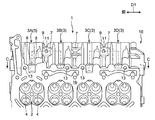
- FIG. 3 is a schematic front view of the intake side portion of the cylinder head according to the embodiment as seen from the front side of the engine.
- FIG. 2 is a schematic side view of the cylinder head of FIG. 1 viewed from the intake side (a view in the direction of arrow A in FIG. 1 ). It is a bottom view of the cylinder head of FIG.
- FIG. 2 is a cross-sectional view (cross-sectional view taken along the line BB of FIG. 1) showing the inside of an intake port of the cylinder head of FIG.
- A) is a cross-sectional view (cross-sectional view taken along the line CC of FIG. 3) showing the arrangement of the inlet and the outlet in the cylinder head of FIG. 1, and (b) shows the resin portion from FIG. 5(a).
- FIG. FIG. 6 is a cross-sectional view [cross-sectional view taken along the line DD in FIG. 5(b)] showing a configuration of a resin passage. It is the figure which expanded one of the intake ports of FIG. 4, and abbreviate
- 8A is a plan view showing an example of a core for molding an intake port
- FIG. 8B is a sectional view taken along the line EE of FIG. 8A.
- FIG. 8 is a cross-sectional view showing a discharge port and a gas passage according to a modification [a view corresponding to FIG. 5B].
- FIG. 1 is a schematic front view of an intake side portion of a cylinder head 1 according to the present embodiment as viewed from the front side of an engine
- FIG. 2 is a side view of the cylinder head 1 (a view in the direction of arrow A in FIG. 1).
- the cylinder head 1 is a component that constitutes, for example, an engine mounted on a vehicle.
- This embodiment exemplifies a cylinder head 1 of an engine in which four cylinders are arranged side by side in a row, and one cylinder is provided with two intake valves and two exhaust valves.
- the engine of the present embodiment includes a cylinder injection valve (not shown) that injects fuel into the combustion chamber 2 (see FIG. 3) and a port injection valve (not shown) that injects fuel into the intake port 3. Equipped.
- the side to which the cylinder block (not shown) is fixed with respect to the cylinder head 1 is referred to as "lower side", and the opposite side is referred to as “upper side” to determine the vertical direction of the cylinder head 1.
- the vertical direction of the cylinder head 1 does not necessarily have to match the vertical direction (vertical direction) when the engine is mounted on a vehicle or the like.
- the simple term “vertical direction” means the vertical direction of the cylinder head 1.
- 3 is a bottom view of the cylinder head 1 (a view of the cylinder head 1 viewed from the bottom surface 1b side)
- FIG. 4 is a cross-sectional view showing the inside of the intake port 3 (a cross section taken along the line BB in FIG. 1). Figure).
- the cylinder head 1 has a cylinder head body 10 formed by casting using, for example, aluminum or an aluminum alloy, and a resin portion 20 arranged along the inner surface of the intake port 3.
- the cylinder head main body 10 constitutes the main body of the cylinder head 1.
- the components other than the resin portion 20 of the cylinder head 1 (such as the above-mentioned intake port 3, the mounting holes 5 and 6 and the boss portion 8 described later) are provided in the cylinder head body 10. 2 and 4 and FIG. 5A described later, the resin portion 20 is shown with dots for easy understanding.
- the cylinder head 1 includes an intake port 3, a port injection valve mounting hole 5, a cylinder injection valve mounting hole 6, and a boss portion 8 to which a delivery pipe connected to the cylinder injection valve is fixed. It is formed for each cylinder.
- the intake port 3 and the mounting holes 5 and 6 open in the wall portion 1a of the cylinder head 1 on the intake side. Further, the boss portion 8 is provided at a position of the wall portion 1a adjacent to the mounting hole 6 of the in-cylinder injection valve.
- An intake manifold (not shown) is connected to the opening 3e (upstream end) of the intake port 3 in the wall portion 1a. 2 to 4 and FIGS. 5(a) and 5(b) which will be described later, the reference numerals of the mounting holes 5 and 6, the boss portion 8 and the like that are similarly provided in each of the four cylinders are given to only one cylinder.
- the lower surface 1b of the cylinder head 1 (hereinafter, also referred to as “cylinder head lower surface 1b") is machined into a flat surface orthogonal to the vertical direction, and serves as a joint surface with the cylinder block. As shown in FIG. 3, a combustion chamber 2 forming the upper part of the cylinder is recessed in the lower surface 1b of the cylinder head.
- the cylinder head 1 is coupled to the cylinder block with a gasket (not shown) interposed between the cylinder head lower surface 1b and the cylinder block upper surface. That is, the cylinder head lower surface 1b and the cylinder block are joined.
- the four intake ports 3 are arranged in a line.
- the direction D1 in which the four intake ports 3 are lined up is referred to as the “port side-by-side direction D1”.
- the four intake ports 3 are referred to as the first intake port 3A, the second intake port 3B, the third intake port 3C, and the fourth intake port 3D in order from the front side of the engine. ..
- the port juxtaposition direction D1 coincides with each of the front-rear direction of the engine and the cylinder row direction (direction in which the cylinders are arranged), and is orthogonal to the vertical direction.
- each intake port 3 is formed in a bifurcated shape that communicates with the combustion chamber 2 via two intake valve holes 4.
- intake air flows in a direction D2 from the opening 3e toward the intake valve hole 4.
- the flow direction D2 of the intake air is referred to as "intake direction D2".
- a center line O of the intake port 3 along the intake direction D2 is shown by a dashed line.
- the center line O corresponds to a line connecting the center points of the cross sections orthogonal to the intake direction D2 in the upstream portion of the intake port 3 relative to the bifurcated portion.
- the cylinder head 1 includes a rib portion 7 provided between the outer walls of two intake ports 3 adjacent to each other, and a seating surface 9 formed on the rib portion 7. There is.
- the rib portion 7 has a function of reinforcing the cylinder head 1. In the present embodiment, between the outer walls of the first intake port 3A and the second intake port 3B, between the outer walls of the second intake port 3B and the third intake port 3C, and between the outer walls of the third intake port 3C and the fourth intake port 3D.
- the case where the rib portion 7 is formed in each of the spaces will be exemplified.
- the seat surface 9 is provided in parallel with the cylinder head lower surface 1b between the two intake ports 3 adjacent to each other.
- the rib portion 7 between the first intake port 3A and the second intake port 3B and the rib portion 7 between the third intake port 3C and the fourth intake port 3D are integrally provided.
- the sitting surface 9 is illustrated.
- Each seat surface 9 is formed in a flat shape facing the same side (lower side) as the cylinder head lower surface 1b. Both the rib portion 7 and the seat surface 9 are arranged on the upstream side (intake manifold side) of the intake port 3 with respect to the mounting hole 6 and the boss portion 8 of the in-cylinder injection valve.
- the resin portion 20 is a heat insulating member that suppresses the heat of the cylinder head body 10 from being transferred to the intake air.
- the resin portion 20 is formed of a resin having a lower thermal conductivity than the material of the cylinder head body 10, and more preferably a resin having a high heat resistance.
- the resin portion 20 is arranged along the inner surface of the portion of the entire length of the intake port 3 excluding the portion on the intake valve hole 4 side (downstream portion).
- the resin portion 20 is formed by injection molding.
- the resin portion 21 provided between the two resin portions 20 adjacent to each other is referred to as a “connecting resin portion 21”.
- the connecting resin portion 21 is formed when the resin portion 20 is molded.
- the connecting resin part 21 of the present embodiment is disposed between the two resin parts 20 arranged in the first intake port 3A and the second intake port 3B and in the third intake port 3C and the fourth intake port 3D. It is provided between each of the two resin portions 20.
- FIG. 5A is a sectional view taken along the line CC of FIG. 3, and FIG. 5B is a view in which the resin portion 20 is omitted from FIG. 5A (that is, before the resin portion 20 is arranged). It is a cross-sectional view of the cylinder head body 10.
- the cylinder head 1 has a structure for supplying the molten resin to be the resin portion 20 to the inner surface of the intake port 3 when the resin portion 20 is injection-molded.
- a resin passage 12, a discharge port 13 and a gas passage 14 are provided.
- the two-dot chain line shown in each intake port 3 in FIG. 5B and FIG. 7 described later is a contour line of a mold used for injection molding of the resin portion 20.
- the injection port 11 is a supply port into which the tip of the injection machine 40 for injecting the molten resin is inserted to supply (inject) the molten resin.
- the exhaust port 13 is a gas vent port for expelling the gas (air) in the intake port 3 when the molten resin is injected into the injection port 11.
- Both the inlet 11 and the outlet 13 are open to the outside of the cylinder head 1.
- the outlet port 13 is provided for each intake port 3, whereas only one inlet port 11 is provided for the two intake ports 3.
- the outlet 13 is dedicated to each intake port 3, while the inlet 11 is shared by the two intake ports 3.
- the inlet 11 is specifically formed between two intake ports 3 adjacent to each other.
- the injection port 11 of the present embodiment is formed in each rib portion 7 integrally provided with the above-mentioned seat surface 9 and opens in each seat surface 9. That is, the inlet 11 is provided between the first intake port 3A and the second intake port 3B and between the third intake port 3C and the fourth intake port 3D, respectively.
- the two inlets 11 have the same circular shape.
- the resin passage 12 is a space through which the molten resin flows to the resin portion 20 when the molten resin is injected from the injection port 11.
- the resin passage 12 extends from the inlet 11 to each of the two intake ports 3 on both sides of the inlet 11. In other words, the resin passage 12 connects the inlet 11 and the intake ports 3 on both sides of the inlet 11.
- the resin passage 12 opens to the outside of the cylinder head 1 through the injection port 11 and also to the inner surface of the intake port 3.
- the opening 15 of the resin passage 12 on the inner surface of each intake port 3 is referred to as "resin inlet 15".
- the resin inlet 15 is a portion that serves as an inlet for the molten resin in the intake port 3 when the resin portion 20 is injection molded.
- the resin inlet 15 of the present embodiment has a larger opening area than the injection port 11.
- the molten resin solidified in the resin passage 12 becomes the above-mentioned connecting resin portion 21.
- the resin passage 12 of the present embodiment has an injection portion 12a that extends perpendicularly to the seat surface 9 from the injection port 11 and a distribution portion 12b that intersects the injection portion 12a and extends to the two intake ports 3. It has a T-shaped branched shape.
- the injection part 12a is a part to which the tip of the injection machine 40 is connected and the molten resin is supplied.
- the injection part 12a of the present embodiment extends straight upward from the injection port 11. That is, the injection part 12a is extended in the up-down direction between the two intake ports 3 adjacent to each other.
- the shape of the cross section (cross section perpendicular to the vertical direction) of the injection portion 12a is circular.
- the distribution part 12b is a part that distributes the molten resin flowing through the injection part 12a to the two intake ports 3. As shown in FIG. 6, the distribution portion 12b extends along the intake direction D2 between two intake ports 3 adjacent to each other, and communicates with each of the two intake ports 3 on both sides.
- the distribution portion 12b of the present embodiment extends straight along each of the port juxtaposed direction D1 and the intake direction D2.
- the cross-sectional shape along the intake direction D2 and the vertical direction is an elliptical shape having a long axis extending in the intake direction D2. That is, in the distributor 12b, the length dimension L in the intake direction D2 is set to be larger than the height dimension H in the direction orthogonal to the port juxtaposed direction D1 and the intake direction D2 (H ⁇ L). Further, in the distributor 12b of the present embodiment, the length dimension L described above is set to be larger than the width dimension W in the port juxtaposing direction D1 (see FIG. 7) (W ⁇ L).
- each outlet 13 is provided at a position different from the inlet 11.
- each injection port 11 is located closer to the intake manifold side than the mounting hole 6 and the boss portion 8 of the in-cylinder injection valve, while each discharge port 13 is more combustion chamber than the injection port 11 and the boss portion 8. It is located on the second side and opens to the cylinder head lower surface 1b.
- each inlet 11 does not overlap with the intake port 3 in the vertical direction (shifts in the port juxtaposed direction D1), whereas the outlet 13 of the present embodiment does not move vertically. It is provided so as to overlap with the intake port 3 in the direction (that is, below the intake port 3).
- the four outlets 13 have the same circular shape.
- the gas passage 14 is a space where the gas expelled from the intake port 3 flows toward the outside of the cylinder head 1 when the molten resin is injected from the injection port 11.
- the gas passage 14 extends from one intake port 3 to an exhaust port 13 provided for the intake port 3. In other words, the gas passage 14 communicates with one intake port 3 and one exhaust port 13 provided therein.
- the gas passage 14 opens to the inner surface of the intake port 3 and also to the outside of the cylinder head 1 through the exhaust port 13.
- the gas passage 14 of the present embodiment extends vertically.
- the cross section of the gas passage 14 (cross section orthogonal to the vertical direction) has a circular shape.
- the opening 16 of the gas passage 14 on the inner surface of each intake port 3 is referred to as a “resin outlet 16”.
- the resin outlet 16 is a portion serving as an outlet for gas and molten resin in the intake port 3 when the resin portion 20 is injection molded.
- FIG. 7 is an enlarged view of the fourth intake port 3D in FIG. 4 with the resin portion 20 omitted.
- the resin inlet 15 and the resin outlet 16 on the inner surface of one intake port 3 are located apart from each other (shifted) in the intake direction D2.
- the resin inlet 15 is located upstream of the resin outlet 16 in the intake direction D2.
- the resin inlet 15 and the resin outlet 16 on the inner surface of one intake port 3 are arranged so as to sandwich the above-mentioned center line O (that is, on both sides of the center line O) when viewed from above and below (for example, in a bottom view). Has been done.
- the resin inlet 15 and the resin outlet 16 of the present embodiment are located apart from each other in the port juxtaposition direction D1 and the intake direction D2 when the intake port 3 is viewed from above and below, and both A center line O is interposed between them.
- the cylinder head 1 is manufactured by the method of molding the intake port 3, the inlet 11 and the resin passage 12 in the cylinder head body 10 described above and by disposing the resin portion 20 in the intake port 3 of the cylinder head body 10. The method and will be described.
- the cylinder head body 10 is molded by casting.
- the cylinder head body 10 has an outer shape molded by a mold (not shown) (for example, an upper mold and a lower mold), and an internal space such as the intake port 3, the injection port 11 and the resin passage 12 has a shape as shown in FIG. It is molded using a core 30 as shown in (b).
- the core 30 includes an intake port portion 33 arranged at a position that becomes the intake port 3, an injection port portion 31 arranged at a position that becomes the injection port 11, and a resin passage portion arranged at a position that becomes the resin passage 12. 32 and.
- the extension portion 34 extending from the position that becomes the opening 3e of the intake port 3 in each intake port portion 33, and the connection portion 35 that connects the extension portions 34 adjacent to each other. And further.
- the extension portion 34 and the connecting portion 35 are portions arranged on the upstream side of the intake port 3 of the cylinder head body 10.
- the four intake port parts 33 are integrally provided (as one core 30) by being connected via the extending part 34 and the connecting part 35.
- the four intake port parts 33 are sequentially arranged from the front side of the engine in the order of the first intake port part 33A, the second intake port part 33B, the third intake port part 33C, and the third intake port part 33C.
- Four intake ports 3D are sequentially arranged from the front side of the engine in the order of the first intake port part 33A, the second intake port part 33B, the third intake port part 33C, and the third intake port part 33C.
- Four intake ports 3D are sequentially arranged from the front side of the engine in the order of the first intake port part 33A, the second intake port part 33B, the third intake port part 33C, and the third intake port part 33C.
- Four intake ports 3D are sequentially arranged from the front side of the engine in the
- the inlet 11 and the resin passage 12 of the present embodiment are provided between the first intake port 3A and the second intake port 3B and between the third intake port 3C and the fourth intake port 3D, respectively. Will be placed. Therefore, in the core 30, the injection port portion 31 and the resin passage portion 32 are provided between the first intake port portion 33A and the second intake port portion 33B and between the third intake port portion 33C and the fourth intake port portion 33D. It is located in two places, the room and the room.
- the resin passage portion 32 includes an injection core portion 32a arranged at a position to be the injection portion 12a and a distribution core portion 32b arranged at a position to be the distribution portion 12b.
- the distribution unit 12b that communicates the first intake port 3A and the second intake port 3B and the distribution unit 12b that communicates the third intake port 3C and the fourth intake port 3D are provided. It is provided. Therefore, in the core 30, the first intake port portion 33A and the second intake port portion 33B are connected by the distribution core portion 32b, and the third intake port portion 33C and the fourth intake port portion 34D are also distributed core portion 32b. Are connected by.
- the cylinder head body 10 is molded by pouring a molten metal obtained by melting a material (for example, aluminum or an aluminum alloy) to be the cylinder head body 10 from the spout while the core 30 is placed inside the mold and solidifying the molten metal. To be done.
- a material for example, aluminum or an aluminum alloy
- the resin portion 20 is formed by injection molding. Specifically, first, a mold is arranged in the intake port 3 of the cylinder head main body 10 (see the chain double-dashed line in FIG. 5(b) and FIG. 7), and a space for supplying the molten resin is defined as an inner surface of the intake port 3. Partition with the outer surface of the mold. Next, the tip of the injection machine 40 is inserted into the injection port 11, and the molten resin is injected from the injection machine 40 into the injection portion 12 a of the resin passage 12.
- the molten resin injected into the injection part 12a is supplied to each inner surface of the two intake ports 3 through the distribution part 12b.
- the molten resin flows along the inner surface of the intake port 3 and spreads into the space between the inner surface of the intake port 3 and the outer surface of the mold.
- the gas in the intake port 3 is expelled toward the outside of the cylinder head body 10 through the gas passage 14 and is exhausted from the exhaust port 13.
- the injection of the molten resin into the injection port 11 is stopped. Then, when the molten resin is solidified, the resin portion 20 is formed in the intake port 3 and the connecting resin portion 21 is formed in the resin passage 12. After that, the cylinder head 1 is completed by removing the mold arranged in the intake port 3.
- the injection port 11 is provided between the two intake ports 3 adjacent to each other, and the resin passage 12 extends from the injection port 11 to each of the intake ports 3 on both sides. Therefore, when the resin portion 20 is molded, if the molten resin is injected into one inlet 11, the molten resin can be supplied to the inner surfaces of the two intake ports 3 through the resin passage 12. That is, the injection port 11 for the molten resin can be shared by the two intake ports 3. Therefore, the number of the injection ports 11 can be reduced as compared with the configuration in which the injection ports 11 are provided for each intake port 3. That is, since the injection port 11 can be efficiently arranged in the narrow space of the cylinder head 1, it is possible to avoid increasing the size of the cylinder head 1. In addition, the degree of freedom in the shape and arrangement of each injection port 11 can be increased.
- the resin portion 20 since the resin portion 20 is arranged in the intake port 3, the resin portion 20 functions as a heat insulating material between the inner surface of the intake port 3 and the intake air flowing in the intake port 3. As a result, the heat transferred from the inner surface of the intake port 3 to the intake air is reduced, so that the temperature rise of the intake air can be suppressed. Therefore, the reduction of the intake air amount and the occurrence of knocking can be suppressed, and the engine performance can be improved.
- the resin passage 12 is extended to each of the two intake ports 3, in the state where the molding of the resin portion 20 is completed, the resin solidified in the resin passage 12 between the two intake ports 3 (the connecting resin portion). 21) is arranged. Thereby, the heat insulating effect between the intake ports 3 can be enhanced. Therefore, according to the cylinder head 1 described above, since the temperature rise of the intake air can be suppressed also from this point, the decrease of the intake air amount and the occurrence of knocking can be suppressed, and the engine performance can be improved. ..
- the resin passage 12 is provided, so that in the core 30 used for casting the intake port 3 and the resin passage 12, two intake port portions 33 are connected to each other by the resin passage portion 32. That is, in the core 30, the two intake port portions 33 adjacent to each other can be connected not only by the extension portion 34 and the connecting portion 35 but also by the resin passage portion 32. As a result, the positional relationship between the intake port portions 33 is easily maintained, so that the shape of the core 30 can be stabilized. Therefore, the positional accuracy of the intake port 3 in the cylinder head 1 can be improved.
- the injection port 11 is opened to the seat surface 9 parallel to the cylinder head lower surface 1b and the resin passage 12 has the injection portion 12a extending from the injection port 11 perpendicularly to the seat surface 9, the molten resin
- the seat surface 9 can be horizontally arranged and the injecting portion 12 can be vertically extended.
- the resin passage 12 has the distribution portion 12b extending between the two intake ports 3 adjacent to each other along the intake direction D2 and communicating with each of these intake ports 3, the molding of the resin portion 20 is completed.
- the resin (connecting resin portion 21) extending along the intake direction D2 can be arranged between the two intake ports 3.
- the heat insulating effect between the intake ports 3 can be enhanced in the intake direction D2.
- the two intake port portions 33 since the two intake port portions 33 are connected by the distribution core portion 32b, the two intake port portions 33 can be connected over a wide range along the intake direction D2. This makes it easier to maintain the positional relationship between the intake port portions 33, so that the shape of the core 30 can be further stabilized and the positional accuracy of the intake port 3 in the cylinder head 1 can be further improved. ..
- the inlet 11 is formed in the rib portion 7 provided between the outer walls of the two intake ports 3 adjacent to each other, the rib portion 7 can reinforce the space between the intake ports 3 and the rib portion 7 Can be utilized as a pedestal portion of the injection port 11. As a result, the space efficiency is improved as compared with the case where a dedicated pedestal portion is provided in the injection port 11, so that the strength and rigidity around the intake port 3 can be increased while suppressing an increase in the size of the cylinder head 1.
- the exhaust port 13 Since the exhaust port 13 is formed at a position different from the injection port 11 and the gas passage 14 extends from the intake port 3 to the exhaust port 13, the inside of the intake port 3 is filled when the molten resin is injected into the injection port 11. This gas can be discharged to the outside through the gas passage 14 and the discharge port 13. Thereby, the molten resin can be more smoothly supplied into the intake port 3. Further, since the resin inlet 15 and the resin outlet 16 are located apart from each other in the intake direction D2 on the inner surface of the intake port 3, the molten resin may flow in the process of flowing from the resin inlet 15 toward the resin outlet 16. Can be made to flow in the intake direction D2 along the inner surface of the intake port 3. Thereby, the molten resin can be easily spread in the intake direction D2. Therefore, the resin portion 20 can be easily molded.
- the resin inlet 15 and the resin outlet 16 are arranged so as to sandwich the center line O along the intake direction D2 of the intake port 3 when viewed from above and below, so that the molten resin is filled with the resin inlet 15
- the molten resin can be made to flow in the port side-by-side direction D1 along the inner surface of the intake port 3 while flowing from the direction toward the resin outlet 16. Thereby, the molten resin can be easily spread in the port parallel direction D1. Therefore, the resin portion 20 can be more easily molded.
- the inlet 11 can be easily arranged closer to the upstream side (intake manifold side). This makes it easier to dispose the injection port 11 apart from the configuration such as the mounting hole 6 and the boss portion 8 of the in-cylinder injection valve provided in the cylinder head 1. That is, since the injection port 11 can be efficiently arranged, interference between the injection port 11 and other components can be easily avoided.
- the discharge port 13 Since the discharge port 13 is open to the cylinder head lower surface 1b, it is possible to process the discharge port 13 at the same time as the cylinder head lower surface 1b is processed when the cylinder head 1 is manufactured. As a result, the processing of the discharge port 13 is facilitated, and the manufacturing cost can be reduced.
- the opening area of the resin inlet 15 is larger than the opening area of the inlet 11, the molten resin injected from the inlet 11 can be more smoothly supplied from the resin inlet 15 into the intake port 3. Therefore, the resin portion 20 can be more easily molded.
- the configuration of the cylinder head 1 described above is an example and is not limited to the above. For example, it may not be the cylinder head of an in-line four-cylinder engine, or the cylinder head of an engine equipped with both an in-cylinder injection valve and a port injection valve.
- the shape of the intake port 3 is not limited to the bifurcated shape described above. Further, the rib portion 7 and the boss portion 8 may be omitted.
- the configuration of the core 30 described above is an example.
- the core 30 may further have a portion arranged at a position to be the discharge port 13 and the gas passage 14. Further, the extending portion 34 and the connecting portion 35 may be omitted.
- the inlet 11, the resin passage 12, the outlet 13, and the gas passage 14 are not limited to those formed by using the core, and may be formed by, for example, drilling.
- the position and the number of the injection ports 11 are not limited to those described above.
- the inlet 11 may be provided between the two intake ports 3 adjacent to each other, and may be provided, for example, between the second intake port 3B and the third intake port 3C described above. Further, in the above-described embodiment, the case where one inlet 11 is provided for the two intake ports 3 is illustrated, but one inlet 11 may be provided for three or more intake ports 3. Good.
- the inlet 11 is provided between the second intake port 3B and the third intake port 3C, and the first intake port 3A and the second intake port 3B, and the third intake port 3C and the fourth intake port 3D are respectively described above.
- the molten resin can be supplied from one injection port 11 to each of the four intake ports 3 by connecting the same with the distribution unit 12a. In this case, the number of injection ports 11 in the cylinder head 1 can be reduced to one.
- the position and the number of the discharge ports 13 are not limited to those described above.
- the outlet 13 may be shared by the plurality of intake ports 3 in the same manner as the inlet 11 is shared by the plurality of intake ports 3.
- the exhaust ports 13 provided for each of the second intake port 3B and the third intake port 3C described above may be integrated into one exhaust port 13'. More specifically, the exhaust port 13' is formed between the second intake port 3B and the third intake port 3C which are adjacent to each other, and the second intake port 3B and the third intake port 3C (that is, both sides of the exhaust port 13' are formed.
- the gas passage 14' may extend from each of the intake ports 3) to the exhaust port 13'.
- the gas in the two intake ports 3 can be collectively discharged from one exhaust port 13'. That is, in the two intake ports 3, the gas outlet 13' can be shared. Therefore, the number of the exhaust ports 13 and 13' can be reduced as compared with the configuration in which the exhaust port 13 is provided for each intake port 3. As a result, the narrow space of the cylinder head 1 can be used more efficiently, the cylinder head 1 can be prevented from becoming larger, and the flexibility of the shape and arrangement of the individual discharge ports 13, 13' can be increased.
- the arrangement of the resin inlet 15 and the resin outlet 16 described above is an example.
- the resin inlet 15 may be located downstream of the resin outlet 16 in the intake direction D2.
- the shapes of the resin passage 12 and the gas passage 14 are not limited to those described above.
- the injection portion 12a of the resin passage 12 may extend obliquely with respect to the vertical direction or may be curved.
- the distribution portion 12b of the resin passage 12 may have a circular cross-sectional shape, or may have a shape other than a circular shape or an oval shape, depending on the characteristics of the resin.
- the size relationship among the length dimension L, the width dimension W, and the height dimension H of the distribution portion 12b is not limited to the above.
- Cylinder head 1b Lower surface (Cylinder head lower surface) 2 Combustion chamber 3 Intake port 7 Rib portion 9 Seat surface 10 Cylinder head body 11 Injection port 12 Resin passage 12a Injection portion 12b Distribution portion 13, 13' Discharge port 14, 14' Gas passage 15 Resin inlet (opening of resin passage) 16 Resin outlet (opening of gas passage) 20 Resin part
Landscapes
- Engineering & Computer Science (AREA)
- Chemical & Material Sciences (AREA)
- Combustion & Propulsion (AREA)
- Mechanical Engineering (AREA)
- General Engineering & Computer Science (AREA)
- Cylinder Crankcases Of Internal Combustion Engines (AREA)
Abstract
シリンダヘッド(1)は、多気筒エンジンの燃焼室に連通する複数の吸気ポート(3)が並設されているとともに、各吸気ポート(3)の内面に沿って配置された樹脂部(20)を有する。シリンダヘッド(1)は、互いに隣接する二つの吸気ポート(3)間において外部に向けて開口する注入口(11)と、注入口(11)から二つの吸気ポート(3)のそれぞれまで延設され、溶融樹脂が注入口(11)から注入された際に樹脂部(20)まで流れる樹脂通路(12)とを備えている。
Description
本発明は、多気筒エンジンのシリンダヘッドに関する。
一般的なエンジンのシリンダヘッドは、例えばアルミニウムやアルミニウム合金を用いた鋳造によって成型されており、熱伝導率が比較的高い。そのため、燃焼室へと繋がる吸気ポートは、燃焼室から伝わる熱によって加熱され、吸気ポートを流通する吸気の温度上昇を招く。吸気の温度が上昇すると吸入空気量が減少するとともにノッキングが発生しやすくなり、エンジン性能を低下させる可能性がある。このような課題に対し、例えば特許文献1には、吸気ポートの内面に樹脂製の断熱部材を配置して、吸気の温度上昇を抑制するようにしたエンジンの吸気通路構造が開示されている。
特許文献1に記載されている断熱部材は、樹脂の射出成型により形成されている。このように断熱材としての樹脂部材を射出成型により形成する場合、シリンダヘッドには、樹脂部材となる溶融樹脂を吸気ポート内へ注入するための注入口が設けられる。しかしながら、シリンダヘッドの外壁には、燃料噴射弁(筒内噴射弁,ポート噴射弁)や、燃料噴射弁に燃料を供給するためのデリバリーパイプといった様々な部材の取付部(ボス)が形成されているため、上記の注入口を形成するためのスペースを確保することが難しい。特に、多気筒エンジンのシリンダヘッドでは複数の吸気ポートが並設されるが、各吸気ポートに専用の注入口を配置するスペースを設けると、シリンダヘッドが大型化するという課題がある。
本件は、このような課題に鑑み案出されたもので、スペース効率を高めてシリンダヘッドの大型化を回避しながら、吸気の温度上昇を抑制することを目的の一つとする。なお、この目的に限らず、後述する発明を実施するための形態に示す各構成により導かれる作用効果であって、従来の技術によっては得られない作用効果を奏することも本件の他の目的である。
(1)ここで開示するシリンダヘッドは、多気筒エンジンの燃焼室に連通する複数の吸気ポートが並設されているとともに、各々の前記吸気ポートの内面に沿って配置された樹脂部を有するシリンダヘッドであって、互いに隣接する二つの前記吸気ポート間において前記シリンダヘッドの外部に向けて開口する注入口と、前記注入口から前記二つの吸気ポートのそれぞれまで延設され、溶融樹脂が前記注入口から注入された際に前記樹脂部まで流れる樹脂通路と、を備えている。
(2)前記シリンダヘッドは、シリンダブロックと接合される平面状のシリンダヘッド下面と平行に設けられた座面を前記二つの吸気ポート間に備えることが好ましい。この場合、前記注入口が、前記座面に開口し、前記樹脂通路が、前記注入口から前記座面に対して垂直に延びる注入部を有することが好ましい。
(3)前記樹脂通路が、前記二つの吸気ポート間において吸気の流れ方向に沿って延びるとともに前記二つの吸気ポートのそれぞれに連通する分配部を有することが好ましい。なお、前記分配部は、前記流れ方向の寸法(長さ寸法)が、前記吸気ポートの並設方向の寸法(幅寸法)と、前記流れ方向及び前記並設方向に直交する方向の寸法(高さ寸法)とのいずれよりも大きいことが好ましい。
(4)前記シリンダヘッドは、前記二つの吸気ポートの外壁間に架設されたリブ部を備えることが好ましい。この場合、前記注入口が、前記リブ部に形成されていることが好ましい。
(4)前記シリンダヘッドは、前記二つの吸気ポートの外壁間に架設されたリブ部を備えることが好ましい。この場合、前記注入口が、前記リブ部に形成されていることが好ましい。
(5)前記シリンダヘッドは、前記注入口と異なる位置で前記外部に向けて開口する排出口と、前記吸気ポートから前記排出口まで延設され、前記溶融樹脂が前記注入口から注入された際に前記吸気ポート内のガスが前記外部へ向けて流れるガス通路と、を備えることが好ましい。この場合、前記内面において、前記樹脂通路の開口と前記ガス通路の開口とが、吸気の流れ方向において互いに離隔して位置することが好ましい。
(6)前記内面において、前記樹脂通路の開口が、前記ガス通路の開口よりも前記流れ方向の上流側に位置することが好ましい。
(7)前記排出口が、互いに隣接する二つの前記吸気ポート間に形成され、前記ガス通路が、前記排出口の両側に位置する前記吸気ポートのそれぞれから前記排出口まで延設されていることが好ましい。
(8)前記排出口は、シリンダブロックと接合される平面状のシリンダヘッド下面に開口することが好ましい。
(7)前記排出口が、互いに隣接する二つの前記吸気ポート間に形成され、前記ガス通路が、前記排出口の両側に位置する前記吸気ポートのそれぞれから前記排出口まで延設されていることが好ましい。
(8)前記排出口は、シリンダブロックと接合される平面状のシリンダヘッド下面に開口することが好ましい。
開示のシリンダヘッドによれば、一つの注入口から樹脂通路を通じて二つの吸気ポートの各内面に溶融樹脂を供給することができる。これにより、吸気ポートごとに注入口を設ける構造と比較して、注入口の個数が削減されるため、シリンダヘッドの狭いスペースに効率良く注入口を配置でき、シリンダヘッドの大型化を回避できる。また、吸気ポート内に配置された樹脂部によって吸気の温度上昇を抑制することができる。
図面を参照して、実施形態としてのシリンダヘッドについて説明する。以下に示す実施形態はあくまでも例示に過ぎず、以下の実施形態で明示しない種々の変形や技術の適用を排除する意図はない。本実施形態の各構成は、それらの趣旨を逸脱しない範囲で種々変形して実施することができる。また、必要に応じて取捨選択することができ、あるいは適宜組み合わせることができる。
[1.シリンダヘッドの構造]
図1は、本実施形態に係るシリンダヘッド1の吸気側部分をエンジンの前側から見た模式的な正面図であり、図2はシリンダヘッド1の側面図(図1のA方向矢視図)である。シリンダヘッド1は、例えば車両に搭載されるエンジンを構成する部品である。本実施形態では、四つの気筒が一列に並設され、一つの気筒に二つの吸気弁と二つの排気弁とが設けられるエンジンのシリンダヘッド1を例示する。また、本実施形態のエンジンには、燃焼室2(図3参照)に燃料を噴射する筒内噴射弁(図示略)と、吸気ポート3に燃料を噴射するポート噴射弁(図示略)とが装備される。
図1は、本実施形態に係るシリンダヘッド1の吸気側部分をエンジンの前側から見た模式的な正面図であり、図2はシリンダヘッド1の側面図(図1のA方向矢視図)である。シリンダヘッド1は、例えば車両に搭載されるエンジンを構成する部品である。本実施形態では、四つの気筒が一列に並設され、一つの気筒に二つの吸気弁と二つの排気弁とが設けられるエンジンのシリンダヘッド1を例示する。また、本実施形態のエンジンには、燃焼室2(図3参照)に燃料を噴射する筒内噴射弁(図示略)と、吸気ポート3に燃料を噴射するポート噴射弁(図示略)とが装備される。
以下、シリンダヘッド1に対してシリンダブロック(図示略)が固定される側を「下側」とし、この逆側を「上側」としてシリンダヘッド1の上下方向を定める。シリンダヘッド1の上下方向は、エンジンが車両等に搭載されたときの上下方向(鉛直方向)と必ずしも一致していなくてよい。以下、単に「上下方向」という場合には、シリンダヘッド1の上下方向を意味する。なお、図3はシリンダヘッド1の下面図(シリンダヘッド1をその下面1b側から見た図)であり、図4は吸気ポート3の内部を示す断面図(図1のB-B矢視断面図)である。
図2に示すように、シリンダヘッド1は、例えばアルミニウムやアルミニウム合金を用いた鋳造によって成型されたシリンダヘッド本体10と、吸気ポート3の内面に沿って配置された樹脂部20とを有する。シリンダヘッド本体10は、シリンダヘッド1の本体部を構成するものである。シリンダヘッド1のうち、樹脂部20以外の構成(上述した吸気ポート3や後述する取付孔5,6及びボス部8等)は、シリンダヘッド本体10に設けられる。なお、図2,図4及び後述する図5(a)ではわかりやすいように、樹脂部20にドットを付して示す。
シリンダヘッド1には、吸気ポート3と、ポート噴射弁の取付孔5と、筒内噴射弁の取付孔6と、筒内噴射弁に接続されるデリバリーパイプが固定されるボス部8とが、気筒ごとに形成されている。吸気ポート3及び各取付孔5,6は、シリンダヘッド1の吸気側の壁部1aに開口している。また、ボス部8は、この壁部1aのうち、筒内噴射弁の取付孔6に隣接する位置に設けられている。なお、この壁部1aにおける吸気ポート3の開口3e(上流端)には、図示しない吸気マニホールドが接続される。図2~図4及び後述する図5(a),(b)では、四つの気筒のそれぞれに同様に設けられる取付孔5,6やボス部8等の符号を、一つの気筒にのみ付す。
シリンダヘッド1の下面1b(以下、「シリンダヘッド下面1b」ともいう)は、上下方向と直交する平面状に加工されており、シリンダブロックとの接合面となる。図3に示すように、シリンダヘッド下面1bには、シリンダの上部を形成する燃焼室2が凹設されている。シリンダヘッド1は、シリンダヘッド下面1bとシリンダブロックの上面との間にガスケット(図示略)が介装された状態で、シリンダブロックと結合される。すなわち、シリンダヘッド下面1bとシリンダブロックとは接合される。
本実施形態のシリンダヘッド1には、四つの吸気ポート3が一列に並設されている。以下、四つの吸気ポート3が並ぶ方向D1を「ポート並設方向D1」という。また、四つの吸気ポート3を互いに区別する場合は、四つの吸気ポート3をエンジンの前側から順に、第一吸気ポート3A,第二吸気ポート3B,第三吸気ポート3C,第四吸気ポート3Dという。ポート並設方向D1は、エンジンの前後方向及びシリンダ列方向(気筒が並ぶ方向)のそれぞれと一致するとともに、上下方向と直交する。
図4に示すように、各吸気ポート3は、二つの吸気バルブ孔4を介して燃焼室2と連通する二股形状に形成されている。各吸気ポート3において、吸気は開口3eから吸気バルブ孔4へと向かう方向D2に流れる。以下、この吸気の流れ方向D2を「吸気方向D2」という。なお、図4には、吸気ポート3の吸気方向D2に沿う中心線Oを一点鎖線で示している。この中心線Oは、吸気ポート3のうち、二股に分岐する部位よりも上流側の部位において、吸気方向D2に直交する断面の中心点を結んだ線に相当する。
図3に示すように、本実施形態のシリンダヘッド1は、互いに隣接する二つの吸気ポート3の外壁間に架設されたリブ部7と、リブ部7に形成された座面9とを備えている。リブ部7は、シリンダヘッド1を補強する機能をもつ。本実施形態では、第一吸気ポート3A及び第二吸気ポート3Bの外壁間と、第二吸気ポート3B及び第三吸気ポート3Cの外壁間と、第三吸気ポート3C及び第四吸気ポート3Dの外壁間とのそれぞれに、リブ部7が形成されている場合を例示する。
座面9は、互いに隣接する二つの吸気ポート3間において、シリンダヘッド下面1bと平行に設けられる。本実施形態では、第一吸気ポート3A及び第二吸気ポート3B間のリブ部7と、第三吸気ポート3C及び第四吸気ポート3D間のリブ部7とのそれぞれに対して一体的に設けられた座面9を例示する。各座面9は、シリンダヘッド下面1bと同じ側(下側)を向く平面状に形成される。リブ部7及び座面9はいずれも、筒内噴射弁の取付孔6及びボス部8よりも吸気ポート3の上流側(吸気マニホールド側)に配置される。
図4に示すように、樹脂部20は、シリンダヘッド本体10の熱が吸気へ伝わるのを抑制する断熱部材である。樹脂部20は、シリンダヘッド本体10の材質よりも熱伝導率の低い樹脂で形成されており、より好ましくは耐熱性の高い樹脂で形成される。樹脂部20は、吸気ポート3の全長のうち、吸気バルブ孔4側の部分(下流部)を除いた部分の内面に沿って配置されている。樹脂部20は、射出成型によって形成される。
本実施形態では、四つの吸気ポート3内に配置される樹脂部20のうち、互いに隣接する二つの樹脂部20が、その相互間に設けられた樹脂部分21によって連結されている。以下、互いに隣接する二つの樹脂部20の間に設けられた樹脂部分21を「連結樹脂部21」という。連結樹脂部21は、樹脂部20を成型する際に形成されるものである。本実施形態の連結樹脂部21は、第一吸気ポート3A及び第二吸気ポート3Bに配置される二つの樹脂部20の間と、第三吸気ポート3C及び第四吸気ポート3Dに配置される二つの樹脂部20の間とのそれぞれに設けられている。
図5(a)は図3のC-C矢視断面図であり、図5(b)は図5(a)から樹脂部20を省略した図(すなわち、樹脂部20が配置される前のシリンダヘッド本体10の断面図)である。図5(b)に示すように、シリンダヘッド1は、樹脂部20を射出成型する際に、樹脂部20となる溶融樹脂を吸気ポート3の内面に供給するための構成として、注入口11,樹脂通路12,排出口13及びガス通路14を備えている。なお、図5(b)及び後述する図7中の各吸気ポート3内に示す二点鎖線は、樹脂部20の射出成型時に用いられる型の輪郭線である。
注入口11は、溶融樹脂を射出する射出機40の先端が挿入されて溶融樹脂が供給(注入)される供給口である。一方、排出口13は、注入口11への溶融樹脂の注入時に吸気ポート3内のガス(空気)を追い出すためのガス抜き口である。注入口11及び排出口13はいずれも、シリンダヘッド1の外部に向けて開口している。本実施形態では、排出口13が各吸気ポート3に対して設けられているのに対し、注入口11が二つの吸気ポート3に対して一つだけ設けられている。言い換えると、排出口13は吸気ポート3ごとに専用化されているのに対し、注入口11は二つの吸気ポート3で共用化されている。
注入口11は、具体的には、互いに隣接する二つの吸気ポート3間に形成されている。本実施形態の注入口11は、上述した座面9が一体的に設けられた各リブ部7に形成されており、各座面9に開口している。すなわち、注入口11は、第一吸気ポート3A及び第二吸気ポート3Bの間と、第三吸気ポート3C及び第四吸気ポート3Dの間とのそれぞれに設けられている。なお、二つの注入口11は、互いに等しい円形状である。
樹脂通路12は、溶融樹脂が注入口11から注入された際に樹脂部20まで流れる空間である。樹脂通路12は、注入口11からその両側の二つの吸気ポート3のそれぞれまで延設されている。言い換えると、樹脂通路12は、注入口11とその両側の各吸気ポート3とを連通している。樹脂通路12は、注入口11を通じてシリンダヘッド1の外部に開口するとともに、吸気ポート3の内面にも開口している。以下、各吸気ポート3の内面における樹脂通路12の開口15を「樹脂入口15」という。樹脂入口15は、樹脂部20が射出成型される際に、吸気ポート3において溶融樹脂の入口となる部位である。本実施形態の樹脂入口15は、注入口11と比べて開口面積が大きく形成されている。樹脂通路12内で固化した溶融樹脂は、上述した連結樹脂部21となる。
本実施形態の樹脂通路12は、注入口11から座面9に対して垂直に延びる注入部12aと、注入部12aに対し交差して二つの吸気ポート3まで延びる分配部12bとを有し、T字状に分岐した形状をなす。注入部12aは、射出機40の先端が接続されて溶融樹脂が供給される部位である。本実施形態の注入部12aは、注入口11から上方へまっすぐに延びている。すなわち、注入部12aは、互いに隣接する二つの吸気ポート3間で上下方向に延設されている。なお、注入部12aの横断面(上下方向と直交する断面)の形状は、円形状である。
分配部12bは、注入部12aを流れる溶融樹脂を二つの吸気ポート3へ分配する部位である。図6に示すように、分配部12bは、互いに隣接する二つの吸気ポート3間において吸気方向D2に沿って延び、両側の二つの吸気ポート3のそれぞれに連通する。本実施形態の分配部12bは、ポート並設方向D1と吸気方向D2とのそれぞれに沿ってまっすぐに延びている。
また、本実施形態の分配部12bは、吸気方向D2及び上下方向に沿う断面の形状が、吸気方向D2に延びる長軸をもつ長円形状とされている。すなわち、分配部12bは、吸気方向D2の長さ寸法Lが、ポート並設方向D1及び吸気方向D2に対して直交する方向の高さ寸法Hよりも大きく設定されている(H<L)。また、本実施形態の分配部12bは、上述した長さ寸法Lが、ポート並設方向D1の幅寸法W(図7参照)よりも大きく設定されている(W<L)。
図3に示すように、各排出口13は、注入口11と異なる位置に設けられる。本実施形態では、各注入口11が筒内噴射弁の取付孔6及びボス部8よりも吸気マニホールド側に位置するのに対し、各排出口13が注入口11やボス部8よりも燃焼室2側に位置しており、シリンダヘッド下面1bに開口している。また、図5(b)に示すように、各注入口11は上下方向において吸気ポート3と重ならない(ポート並設方向D1にずれている)のに対し、本実施形態の排出口13は上下方向において吸気ポート3と重なって(すなわち吸気ポート3の下方に)設けられている。なお、四つの排出口13は、互いに等しい円形状である。
ガス通路14は、溶融樹脂が注入口11から注入された際に、吸気ポート3内から追い出されたガスがシリンダヘッド1の外部へ向けて流れる空間である。ガス通路14は、一つの吸気ポート3からこの吸気ポート3に対して設けられた排出口13まで延設されている。言い換えると、ガス通路14は、一つの吸気ポート3と、これに対して設けられた一つの排出口13とを連通している。ガス通路14は、吸気ポート3の内面に開口するとともに、排出口13を通じてシリンダヘッド1の外部にも開口している。
本実施形態のガス通路14は、上下方向に延設されている。ガス通路14の横断面(上下方向と直交する断面)の形状は、円形状である。以下、各吸気ポート3の内面におけるガス通路14の開口16を「樹脂出口16」という。樹脂出口16は、樹脂部20が射出成型される際に、吸気ポート3においてガス及び溶融樹脂の出口となる部位である。
図7は、図4中の第四吸気ポート3Dを拡大して樹脂部20を省略した図である。図7に例示するように、一つの吸気ポート3の内面における樹脂入口15と樹脂出口16とは、吸気方向D2において互いに離隔して(ずれて)位置する。本実施形態では、樹脂入口15が樹脂出口16よりも吸気方向D2の上流側に位置する。また、一つの吸気ポート3の内面における樹脂入口15と樹脂出口16とは、上下方向から見て(例えば下面視で)、上述した中心線Oを挟んで(すなわち中心線Oの両側に)配置されている。このように、本実施形態の樹脂入口15と樹脂出口16とは、吸気ポート3を上下方向から見た場合、ポート並設方向D1及び吸気方向D2のそれぞれにおいて互いに離隔して位置するとともに、両者の間には中心線Oが介在する。
[2.シリンダヘッドの製造方法]
ここでは、上述したシリンダヘッド本体10における吸気ポート3,注入口11及び樹脂通路12の成型方法と、シリンダヘッド本体10の吸気ポート3内に樹脂部20を配置することでシリンダヘッド1を製造する方法とについて説明する。
ここでは、上述したシリンダヘッド本体10における吸気ポート3,注入口11及び樹脂通路12の成型方法と、シリンダヘッド本体10の吸気ポート3内に樹脂部20を配置することでシリンダヘッド1を製造する方法とについて説明する。
上述したように、シリンダヘッド本体10は鋳造により成型される。シリンダヘッド本体10は、図示しない鋳型(例えば上型,下型)により外形状が成型されるとともに、吸気ポート3,注入口11及び樹脂通路12といった内部の空間が、例えば図8(a),(b)に示すような中子30を用いて成型される。中子30は、吸気ポート3となる位置に配置される吸気ポート部33と、注入口11となる位置に配置される注入口部31と、樹脂通路12となる位置に配置される樹脂通路部32とを有する。また、本実施形態の中子30は、各吸気ポート部33において吸気ポート3の開口3eとなる位置から延出した延出部34と、互いに隣接する延出部34同士を連結する連結部35とを更に有する。
延出部34及び連結部35は、シリンダヘッド本体10の吸気ポート3よりも上流側に配置される部位である。四つの吸気ポート部33は、延出部34及び連結部35を介して連結されることで、一体に(一つの中子30として)設けられている。以下、四つの吸気ポート部33を互いに区別する場合は、四つの吸気ポート部33をエンジンの前側から順に、第一吸気ポート部33A,第二吸気ポート部33B,第三吸気ポート部33C,第四吸気ポート部3Dという。これらの吸気ポート部33A~33Dは、それぞれ吸気ポート3A~3Dに対応するものである。
上述したように、本実施形態の注入口11及び樹脂通路12は、第一吸気ポート3A及び第二吸気ポート3Bの間と、第三吸気ポート3C及び第四吸気ポート3Dの間とのそれぞれに配置される。このため、中子30では、注入口部31及び樹脂通路部32が、第一吸気ポート部33A及び第二吸気ポート部33Bの間と、第三吸気ポート部33C及び第四吸気ポート部33Dの間との二箇所に配置されている。
図8(b)に示すように、樹脂通路部32は、注入部12aとなる位置に配置される注入中子部32aと、分配部12bとなる位置に配置される分配中子部32bとを有する。上述したように、本実施形態では、第一吸気ポート3A及び第二吸気ポート3Bを連通する分配部12bと、第三吸気ポート3C及び第四吸気ポート3Dを連通する分配部12bとの二つが設けられる。このため、中子30では、第一吸気ポート部33A及び第二吸気ポート部33Bが分配中子部32bで連結され、第三吸気ポート部33C及び第四吸気ポート部34Dも分配中子部32bで連結されている。
このような中子30を鋳型の内部に配置した状態で、シリンダヘッド本体10となる材料(例えばアルミニウムやアルミニウム合金)を溶かした溶湯を湯口から流し込み、固化させることで、シリンダヘッド本体10が成型される。
次に、シリンダヘッド本体10の吸気ポート3内に樹脂部20を配置する方法について説明する。上述したように、樹脂部20は、射出成型により形成される。具体的には、まずシリンダヘッド本体10の吸気ポート3内に型〔図5(b)及び図7中の二点鎖線参照〕を配置し、溶融樹脂を供給する空間を吸気ポート3の内面と型の外面とで区画する。次いで、射出機40の先端を注入口11に挿入し、射出機40から樹脂通路12の注入部12aに溶融樹脂を注入する。
注入部12aに注入された溶融樹脂は、分配部12bを通じて二つの吸気ポート3の各内面へと供給される。この溶融樹脂は、吸気ポート3の内面に沿って流れ、吸気ポート3の内面と型の外面との間の空間に広がっていく。これに伴い、吸気ポート3内のガスは、ガス通路14を通じてシリンダヘッド本体10の外部へ向けて追い出され、排出口13から排出される。
吸気ポート3の内面と型の外面との間の空間が溶融樹脂で充填されたら、注入口11への溶融樹脂の注入を停止する。そして、溶融樹脂が固化すると、吸気ポート3内に樹脂部20が形成されるとともに、樹脂通路12内に連結樹脂部21が形成される。その後、吸気ポート3内に配置していた型を取り去れば、シリンダヘッド1が完成する。
[3.作用,効果]
(1)上述したシリンダヘッド1では、互いに隣接する二つの吸気ポート3間に注入口11が設けられ、この注入口11から両側の吸気ポート3のそれぞれまで樹脂通路12が延設される。このため、樹脂部20を成型する際、一つの注入口11に溶融樹脂を注入すれば、樹脂通路12を通じて二つの吸気ポート3の各内面に溶融樹脂を供給することができる。すなわち、二つの吸気ポート3において、溶融樹脂の注入口11を共用化することができる。よって、吸気ポート3ごとに注入口11を設ける構成と比較して、注入口11の個数を削減することができる。つまり、シリンダヘッド1の狭いスペースに効率良く注入口11を配置できることから、シリンダヘッド1の大型化を回避できる。また、個々の注入口11の形状及び配置の自由度を高められる。
(1)上述したシリンダヘッド1では、互いに隣接する二つの吸気ポート3間に注入口11が設けられ、この注入口11から両側の吸気ポート3のそれぞれまで樹脂通路12が延設される。このため、樹脂部20を成型する際、一つの注入口11に溶融樹脂を注入すれば、樹脂通路12を通じて二つの吸気ポート3の各内面に溶融樹脂を供給することができる。すなわち、二つの吸気ポート3において、溶融樹脂の注入口11を共用化することができる。よって、吸気ポート3ごとに注入口11を設ける構成と比較して、注入口11の個数を削減することができる。つまり、シリンダヘッド1の狭いスペースに効率良く注入口11を配置できることから、シリンダヘッド1の大型化を回避できる。また、個々の注入口11の形状及び配置の自由度を高められる。
また、上述したシリンダヘッド1では、吸気ポート3内に樹脂部20が配置されるため、吸気ポート3の内面と吸気ポート3内を流れる吸気との間で樹脂部20が断熱材として機能する。これにより、吸気ポート3の内面から吸気に伝わる熱が低減されるため、吸気の温度上昇を抑制することができる。よって、吸入空気量の減少とノッキングの発生とを抑制でき、エンジン性能の向上を図ることができる。
さらに、樹脂通路12が二つの吸気ポート3のそれぞれまで延設されるため、樹脂部20の成型が完了した状態では、二つの吸気ポート3間に樹脂通路12内で固化した樹脂(連結樹脂部21)が配置される。これにより、吸気ポート3間における断熱効果を高めることができる。したがって、上述したシリンダヘッド1によれば、この点からも吸気の温度上昇を抑制することができるため、吸入空気量の減少とノッキングの発生とを抑制でき、エンジン性能の向上を図ることができる。
なお、樹脂通路12が設けられることで、吸気ポート3及び樹脂通路12の鋳造で用いる中子30では、吸気ポート部33の二つが樹脂通路部32で互いに連結される。すなわち、中子30では、互いに隣接する二つの吸気ポート部33を、延出部34及び連結部35だけでなく、樹脂通路部32によっても連結することができる。これにより、吸気ポート部33同士の位置関係が保持されやすくなるため、中子30の形状を安定化することができる。したがって、シリンダヘッド1における吸気ポート3の位置精度を向上させることができる。
(2)注入口11がシリンダヘッド下面1bと平行な座面9に開口しており、樹脂通路12がこの注入口11から座面9に対して垂直に延びる注入部12aを有するため、溶融樹脂を注入する際に、シリンダヘッド下面1bを水平に配置すれば、座面9も水平に配置できるとともに注入部12を鉛直方向に延ばすことができる。これにより、樹脂部20を成型する際に、シリンダヘッド本体10の姿勢を保持しやすくできるとともに、溶融樹脂の注入方向を鉛直方向とすることができる。よって、溶融樹脂を注入しやすくすることができる。
(3)樹脂通路12が、互いに隣接する二つの吸気ポート3間で吸気方向D2に沿って延びるとともにこれらの吸気ポート3のそれぞれに連通する分配部12bを有するため、樹脂部20の成型が完了した状態では、吸気方向D2に沿って延びる樹脂(連結樹脂部21)を二つの吸気ポート3間に配置できる。これにより、吸気ポート3間の断熱効果を吸気方向D2にわたって高めることができる。また、上述した中子30では、二つの吸気ポート部33が分配中子部32bで連結されるため、二つの吸気ポート部33を吸気方向D2に沿う広範囲にわたって連結することができる。これにより、吸気ポート部33同士の位置関係がより保持されやすくなるため、中子30の形状を更に安定化することができ、シリンダヘッド1における吸気ポート3の位置精度を更に向上させることができる。
(4)注入口11が、互いに隣接する二つの吸気ポート3の外壁間に架設されたリブ部7に形成されているため、リブ部7で吸気ポート3の間を補強できるとともに、リブ部7を注入口11の台座部として活用することができる。これにより、注入口11に専用の台座部を設ける場合と比べてスペース効率が高められるため、シリンダヘッド1の大型化を抑えながら、吸気ポート3の周辺の強度及び剛性を高めることができる。
(5)注入口11と異なる位置に排出口13が形成され、吸気ポート3から排出口13までガス通路14が延設されるため、注入口11への溶融樹脂の注入時に、吸気ポート3内のガスをガス通路14及び排出口13を通じて外部へと排出することができる。これにより、吸気ポート3内に溶融樹脂をよりスムーズに供給することができる。また、吸気ポート3の内面では、樹脂入口15と樹脂出口16とが吸気方向D2において互いに離隔して位置するため、溶融樹脂が樹脂入口15から樹脂出口16に向かってか流れる過程で、溶融樹脂を吸気ポート3の内面に沿わせながら吸気方向D2に流すことができる。これにより、溶融樹脂を吸気方向D2に広がりやすくすることができる。したがって、樹脂部20を成型しやすくすることができる。
さらに、吸気ポート3の内面では、樹脂入口15と樹脂出口16とが上下方向から見て吸気ポート3の吸気方向D2に沿う中心線Oを挟んで配置されているため、溶融樹脂が樹脂入口15から樹脂出口16に向かって流れる過程で、溶融樹脂を吸気ポート3の内面に沿わせながらポート並設方向D1にも流すことができる。これにより、溶融樹脂をポート並設方向D1にも広がりやすくすることができる。したがって、樹脂部20を更に成型しやすくすることができる。
(6)吸気ポート3の内面において、樹脂入口15が樹脂出口16よりも吸気方向D2の上流側に位置するため、注入口11を上流側(吸気マニホールド側)に寄せて配置しやすくできる。これにより、シリンダヘッド1に設けられる筒内噴射弁の取付孔6やボス部8といった構成に対し、注入口11を離隔させて配置しやすくなる。すなわち、注入口11を効率良く配置できることから、注入口11と他の構成との干渉を回避しやすくできる。
(7)排出口13がシリンダヘッド下面1bに開口しているため、シリンダヘッド1の製造時に、シリンダヘッド下面1bを加工するのと同時に排出口13を加工することができる。これにより、排出口13の加工が容易になるため、製造コストの削減を図ることができる。
(8)樹脂入口15の開口面積が注入口11の開口面積と比べて大きいため、注入口11から注入された溶融樹脂を樹脂入口15から吸気ポート3内へよりスムーズに供給することができる。したがって、樹脂部20をより成型しやすくすることができる。
(8)樹脂入口15の開口面積が注入口11の開口面積と比べて大きいため、注入口11から注入された溶融樹脂を樹脂入口15から吸気ポート3内へよりスムーズに供給することができる。したがって、樹脂部20をより成型しやすくすることができる。
[4.変形例]
上述したシリンダヘッド1の構成は一例であって、上述したものに限られない。例えば、直列四気筒エンジンのシリンダヘッドでなくてもよいし、筒内噴射弁及びポート噴射弁の両方を備えたエンジンのシリンダヘッドでなくてもよい。なお、吸気ポート3の形状は、上述したような二股形状に限定されない。また、リブ部7やボス部8が省略されてもよい。
上述したシリンダヘッド1の構成は一例であって、上述したものに限られない。例えば、直列四気筒エンジンのシリンダヘッドでなくてもよいし、筒内噴射弁及びポート噴射弁の両方を備えたエンジンのシリンダヘッドでなくてもよい。なお、吸気ポート3の形状は、上述したような二股形状に限定されない。また、リブ部7やボス部8が省略されてもよい。
上述した中子30の構成は一例である。中子30は、上述した構成に加えて、排出口13及びガス通路14となる位置に配置される部分を更に有していてもよい。また、延出部34及び連結部35が省略されてもよい。なお、注入口11,樹脂通路12,排出口13及びガス通路14は、中子を用いて形成されるものに限らず、例えば、穴あけ加工により形成されてもよい。
注入口11の位置及び個数は、上述したものに限定されない。注入口11は、互いに隣接する二つの吸気ポート3間に設けられればよく、例えば上述した第二吸気ポート3B及び第三吸気ポート3Cの間に設けられてもよい。また、上述した実施形態では、二つの吸気ポート3に対して一つの注入口11が設けられる場合を例示したが、三つ以上の吸気ポート3に対して一つの注入口11が設けられてもよい。例えば、第二吸気ポート3B及び第三吸気ポート3C間に注入口11を設け、第一吸気ポート3A及び第二吸気ポート3B間と、第三吸気ポート3C及び第四吸気ポート3Dとをそれぞれ上述した分配部12aと同様の構成で連結すれば、一つの注入口11から四つの吸気ポート3のそれぞれに溶融樹脂を供給できる。この場合、シリンダヘッド1において注入口11の個数を一つに削減することができる。
排出口13の位置及び個数も、上述したものに限定されない。注入口11を複数の吸気ポート3で共用化するのと同様に、排出口13を複数の吸気ポート3で共用化してもよい。例えば図9に示すように、上述した第二吸気ポート3B及び第三吸気ポート3Cのそれぞれに対して設けられた排出口13を一つの排出口13′に統合してもよい。より具体的には、互いに隣接する第二吸気ポート3B及び第三吸気ポート3C間に排出口13′を形成し、第二吸気ポート3B及び第三吸気ポート3C(すなわち、排出口13′の両側の吸気ポート3)のそれぞれから排出口13′までガス通路14′を延設してもよい。
この場合、溶融樹脂の注入時に、二つの吸気ポート3内のガスを一つの排出口13′からまとめて排出することができる。すなわち、二つの吸気ポート3において、ガスの排出口13′を共用化することができる。よって、吸気ポート3ごとに排出口13を設ける構成と比較して、排出口13,13′の個数を削減することができる。これにより、シリンダヘッド1の狭いスペースをより効率良く利用でき、シリンダヘッド1の大型化を回避できるとともに、個々の排出口13,13′の形状及び配置の自由度を高められる。
また、この場合、ガス通路14′が二つの吸気ポート3のそれぞれまで延設されるため、ガス通路14′内にも溶融樹脂を流して固化させれば、上述した連結樹脂部21と同様に、吸気ポート3間における断熱効果を高めることができる。さらに、吸気ポート3の鋳造で用いる中子にガス通路14′に対応する部分を設ければ、この中子においてガス通路14′に対応する部分が、上述した中子30における樹脂通路部32と同様に、吸気ポート3に対応する部分の二つを連結する。このため、中子の形状を安定化できるとともに、シリンダヘッド1における吸気ポート3の位置精度を向上させることができる。なお、図9には二つの吸気ポート3に対して一つの排出口13′が設けられる場合を例示したが、三つ以上の吸気ポート3に対して一つの排出口13′が設けられてもよい。
上述した樹脂入口15及び樹脂出口16の配置は一例である。樹脂入口15は、樹脂出口16よりも吸気方向D2の下流側に位置してもよい。また、樹脂通路12及びガス通路14の形状も、上述したものに限定されない。例えば、樹脂通路12の注入部12aは、上下方向に対して傾斜して延びていてもよいし、湾曲していてもよい。また、樹脂通路12の分配部12bは、樹脂の特性によるため、断面形状が円形であってもよく、また、円形や長円形状以外であってもよい。なお、分配部12bの長さ寸法L,幅寸法W及び高さ寸法Hの大小関係も、上述したものに限定されない。
1 シリンダヘッド
1b 下面(シリンダヘッド下面)
2 燃焼室
3 吸気ポート
7 リブ部
9 座面
10 シリンダヘッド本体
11 注入口
12 樹脂通路
12a 注入部
12b 分配部
13,13′ 排出口
14,14′ ガス通路
15 樹脂入口(樹脂通路の開口)
16 樹脂出口(ガス通路の開口)
20 樹脂部
1b 下面(シリンダヘッド下面)
2 燃焼室
3 吸気ポート
7 リブ部
9 座面
10 シリンダヘッド本体
11 注入口
12 樹脂通路
12a 注入部
12b 分配部
13,13′ 排出口
14,14′ ガス通路
15 樹脂入口(樹脂通路の開口)
16 樹脂出口(ガス通路の開口)
20 樹脂部
Claims (8)
- 多気筒エンジンの燃焼室に連通する複数の吸気ポートが並設されているとともに、各々の前記吸気ポートの内面に沿って配置された樹脂部を有するシリンダヘッドであって、
互いに隣接する二つの前記吸気ポート間において前記シリンダヘッドの外部に向けて開口する注入口と、
前記注入口から前記二つの吸気ポートのそれぞれまで延設され、溶融樹脂が前記注入口から注入された際に前記樹脂部まで流れる樹脂通路と、を備えた
ことを特徴とする、シリンダヘッド。 - シリンダブロックと接合される平面状のシリンダヘッド下面と平行に設けられた座面を前記二つの吸気ポート間に備え、
前記注入口が、前記座面に開口し、
前記樹脂通路が、前記注入口から前記座面に対して垂直に延びる注入部を有する
ことを特徴とする、請求項1記載のシリンダヘッド。 - 前記樹脂通路が、前記二つの吸気ポート間において吸気の流れ方向に沿って延びるとともに前記二つの吸気ポートのそれぞれに連通する分配部を有する
ことを特徴とする、請求項1又は2記載のシリンダヘッド。 - 前記二つの吸気ポートの外壁間に架設されたリブ部を備え、
前記注入口が、前記リブ部に形成されている
ことを特徴とする、請求項1~3のいずれか1項に記載のシリンダヘッド。 - 前記注入口と異なる位置で前記外部に向けて開口する排出口と、
前記吸気ポートから前記排出口まで延設され、前記溶融樹脂が前記注入口から注入された際に前記吸気ポート内のガスが前記外部へ向けて流れるガス通路と、を備え、
前記内面において、前記樹脂通路の開口と前記ガス通路の開口とが、吸気の流れ方向において互いに離隔して位置する
ことを特徴とする、請求項1~4のいずれか1項に記載のシリンダヘッド。 - 前記内面において、前記樹脂通路の開口が、前記ガス通路の開口よりも前記流れ方向の上流側に位置する
ことを特徴とする、請求項5記載のシリンダヘッド。 - 前記排出口が、互いに隣接する二つの前記吸気ポート間に形成され、
前記ガス通路が、前記排出口の両側に位置する前記吸気ポートのそれぞれから前記排出口まで延設されている
ことを特徴とする、請求項5又は6記載のシリンダヘッド。 - 前記排出口は、シリンダブロックと接合される平面状のシリンダヘッド下面に開口する
ことを特徴とする、請求項5~7のいずれか1項に記載のシリンダヘッド。
Priority Applications (1)
| Application Number | Priority Date | Filing Date | Title |
|---|---|---|---|
| JP2020565700A JP7136232B2 (ja) | 2019-01-07 | 2019-12-25 | シリンダヘッド |
Applications Claiming Priority (2)
| Application Number | Priority Date | Filing Date | Title |
|---|---|---|---|
| JP2019-000831 | 2019-01-07 | ||
| JP2019000831 | 2019-01-07 |
Publications (1)
| Publication Number | Publication Date |
|---|---|
| WO2020145155A1 true WO2020145155A1 (ja) | 2020-07-16 |
Family
ID=71521363
Family Applications (1)
| Application Number | Title | Priority Date | Filing Date |
|---|---|---|---|
| PCT/JP2019/050942 Ceased WO2020145155A1 (ja) | 2019-01-07 | 2019-12-25 | シリンダヘッド |
Country Status (2)
| Country | Link |
|---|---|
| JP (1) | JP7136232B2 (ja) |
| WO (1) | WO2020145155A1 (ja) |
Citations (10)
| Publication number | Priority date | Publication date | Assignee | Title |
|---|---|---|---|---|
| JPH0269043U (ja) * | 1988-11-14 | 1990-05-25 | ||
| JPH0341151U (ja) * | 1989-08-28 | 1991-04-19 | ||
| US5842342A (en) * | 1997-02-21 | 1998-12-01 | Northrop Grumman Corporation | Fiber reinforced ceramic matrix composite internal combustion engine intake/exhaust port liners |
| JPH11182367A (ja) * | 1997-12-15 | 1999-07-06 | Toyota Motor Corp | 樹脂製インテークマニホールド |
| JP2011094515A (ja) * | 2009-10-28 | 2011-05-12 | Toyoda Gosei Co Ltd | シリンダヘッドブロック |
| JP2014008638A (ja) * | 2012-06-28 | 2014-01-20 | Aisan Ind Co Ltd | デリバリパイプの成形方法 |
| WO2015093256A1 (ja) * | 2013-12-19 | 2015-06-25 | 東洋製罐グループホールディングス株式会社 | プラスチックの成形方法 |
| JP2016205267A (ja) * | 2015-04-24 | 2016-12-08 | 三菱自動車工業株式会社 | シリンダヘッドのポート部の製造方法 |
| JP2018003601A (ja) * | 2016-06-27 | 2018-01-11 | 三菱自動車工業株式会社 | エンジンの吸気通路構造 |
| JP2018003602A (ja) * | 2016-06-27 | 2018-01-11 | 三菱自動車工業株式会社 | エンジンの吸気通路構造 |
-
2019
- 2019-12-25 JP JP2020565700A patent/JP7136232B2/ja active Active
- 2019-12-25 WO PCT/JP2019/050942 patent/WO2020145155A1/ja not_active Ceased
Patent Citations (10)
| Publication number | Priority date | Publication date | Assignee | Title |
|---|---|---|---|---|
| JPH0269043U (ja) * | 1988-11-14 | 1990-05-25 | ||
| JPH0341151U (ja) * | 1989-08-28 | 1991-04-19 | ||
| US5842342A (en) * | 1997-02-21 | 1998-12-01 | Northrop Grumman Corporation | Fiber reinforced ceramic matrix composite internal combustion engine intake/exhaust port liners |
| JPH11182367A (ja) * | 1997-12-15 | 1999-07-06 | Toyota Motor Corp | 樹脂製インテークマニホールド |
| JP2011094515A (ja) * | 2009-10-28 | 2011-05-12 | Toyoda Gosei Co Ltd | シリンダヘッドブロック |
| JP2014008638A (ja) * | 2012-06-28 | 2014-01-20 | Aisan Ind Co Ltd | デリバリパイプの成形方法 |
| WO2015093256A1 (ja) * | 2013-12-19 | 2015-06-25 | 東洋製罐グループホールディングス株式会社 | プラスチックの成形方法 |
| JP2016205267A (ja) * | 2015-04-24 | 2016-12-08 | 三菱自動車工業株式会社 | シリンダヘッドのポート部の製造方法 |
| JP2018003601A (ja) * | 2016-06-27 | 2018-01-11 | 三菱自動車工業株式会社 | エンジンの吸気通路構造 |
| JP2018003602A (ja) * | 2016-06-27 | 2018-01-11 | 三菱自動車工業株式会社 | エンジンの吸気通路構造 |
Also Published As
| Publication number | Publication date |
|---|---|
| JP7136232B2 (ja) | 2022-09-13 |
| JPWO2020145155A1 (ja) | 2021-09-27 |
Similar Documents
| Publication | Publication Date | Title |
|---|---|---|
| CN101400462B (zh) | 用于制造气缸盖的方法以及气缸盖 | |
| CN103775234B (zh) | 气缸盖的水套结构 | |
| US20160186641A1 (en) | Cooling structure of internal combustion engine | |
| US7100559B2 (en) | Engine air intake manifold | |
| CN103775235B (zh) | 气缸盖的水套结构 | |
| CN103775230A (zh) | 气缸盖的水套结构 | |
| JP2014084736A (ja) | シリンダヘッドのウォータージャケット構造 | |
| US10975812B2 (en) | Method and system for manufacturing a family of intake manifolds for a family of internal combustion engines | |
| JP2018184939A (ja) | 内燃機関の冷却構造 | |
| JP2014084738A (ja) | シリンダヘッドの冷却液通路構造 | |
| WO2020145155A1 (ja) | シリンダヘッド | |
| JP2004270588A (ja) | エンジンの吸気装置 | |
| JP7136233B2 (ja) | シリンダヘッド | |
| JP3622445B2 (ja) | 直噴式内燃機関のシリンダヘッド製造方法 | |
| JP3618593B2 (ja) | 内燃機関におけるシリンダヘッドの構造 | |
| JP7040645B2 (ja) | シリンダヘッド | |
| JP7173166B2 (ja) | シリンダヘッド | |
| CN104968924B (zh) | 内燃机 | |
| WO2020145158A1 (ja) | シリンダヘッド | |
| JP7491656B2 (ja) | 吸気マニホールド | |
| JPH10169504A (ja) | 内燃機関のシリンダヘッド | |
| JP6461199B2 (ja) | 内燃機関 | |
| JP5782728B2 (ja) | 内燃機関の吸気構造 | |
| JPH10280954A (ja) | シリンダヘッドの冷却構造 |
Legal Events
| Date | Code | Title | Description |
|---|---|---|---|
| 121 | Ep: the epo has been informed by wipo that ep was designated in this application |
Ref document number: 19908294 Country of ref document: EP Kind code of ref document: A1 |
|
| ENP | Entry into the national phase |
Ref document number: 2020565700 Country of ref document: JP Kind code of ref document: A |
|
| NENP | Non-entry into the national phase |
Ref country code: DE |
|
| 122 | Ep: pct application non-entry in european phase |
Ref document number: 19908294 Country of ref document: EP Kind code of ref document: A1 |