WO2020145067A1 - アクチュエータを制御する制御装置 - Google Patents
アクチュエータを制御する制御装置 Download PDFInfo
- Publication number
- WO2020145067A1 WO2020145067A1 PCT/JP2019/049745 JP2019049745W WO2020145067A1 WO 2020145067 A1 WO2020145067 A1 WO 2020145067A1 JP 2019049745 W JP2019049745 W JP 2019049745W WO 2020145067 A1 WO2020145067 A1 WO 2020145067A1
- Authority
- WO
- WIPO (PCT)
- Prior art keywords
- drive
- signal
- fuel injection
- control device
- voltage
- Prior art date
- Legal status (The legal status is an assumption and is not a legal conclusion. Google has not performed a legal analysis and makes no representation as to the accuracy of the status listed.)
- Ceased
Links
Images


Classifications
-
- F—MECHANICAL ENGINEERING; LIGHTING; HEATING; WEAPONS; BLASTING
- F02—COMBUSTION ENGINES; HOT-GAS OR COMBUSTION-PRODUCT ENGINE PLANTS
- F02D—CONTROLLING COMBUSTION ENGINES
- F02D41/00—Electrical control of supply of combustible mixture or its constituents
- F02D41/22—Safety or indicating devices for abnormal conditions
-
- F—MECHANICAL ENGINEERING; LIGHTING; HEATING; WEAPONS; BLASTING
- F02—COMBUSTION ENGINES; HOT-GAS OR COMBUSTION-PRODUCT ENGINE PLANTS
- F02D—CONTROLLING COMBUSTION ENGINES
- F02D45/00—Electrical control not provided for in groups F02D41/00 - F02D43/00
-
- Y—GENERAL TAGGING OF NEW TECHNOLOGICAL DEVELOPMENTS; GENERAL TAGGING OF CROSS-SECTIONAL TECHNOLOGIES SPANNING OVER SEVERAL SECTIONS OF THE IPC; TECHNICAL SUBJECTS COVERED BY FORMER USPC CROSS-REFERENCE ART COLLECTIONS [XRACs] AND DIGESTS
- Y02—TECHNOLOGIES OR APPLICATIONS FOR MITIGATION OR ADAPTATION AGAINST CLIMATE CHANGE
- Y02T—CLIMATE CHANGE MITIGATION TECHNOLOGIES RELATED TO TRANSPORTATION
- Y02T10/00—Road transport of goods or passengers
- Y02T10/10—Internal combustion engine [ICE] based vehicles
- Y02T10/40—Engine management systems
Definitions
- the present invention relates to a control device for controlling an actuator, for example, a technique for controlling a fuel injection valve (injector) that supplies fuel to a combustion chamber of an internal combustion engine.
- a fuel injection valve injector
- a control device for controlling an internal combustion engine when an abnormality/failure of a mechanical component or a control component affecting torque of the internal combustion engine (hereinafter referred to as “engine torque”) is detected, the operator is notified of the abnormality of the internal combustion engine. In addition to the notification, it also executes a fail-safe function such as a fuel injection cut function, an ignition control cut function, and a throttle fixed opening setting function.
- engine torque an abnormality/failure of a mechanical component or a control component affecting torque of the internal combustion engine
- Patent Document 1 a diagnosis period for diagnosing the fuel injection cut function (fail safe function) is set before the internal combustion engine is started, and a drive permission/prohibition signal is output to the injector driver during the diagnosis period of the fuel injection cut function.
- the abnormality diagnosis of the fuel injection cut function is executed by monitoring the signal state of the operating state monitoring port (Disable port) of the injector driver at that time.
- Patent Document 1 since the signal state of the operating state monitoring port of the injector driver is monitored and the fuel injection signal output from the final injector driver is not monitored, fail-safe at the time of failure of the injector driver. The function cannot be correctly diagnosed. As a result, when the fail-safe function is required, the injector driver that has received the drive pulse output cannot be stopped, and abnormal engine torque may occur.
- the present invention has been made in view of the above circumstances, and an object of the present invention is to make it possible to perform abnormality diagnosis in a drive permission setting state even when a drive circuit that drives an actuator such as a fuel injection valve fails. ..
- a control device for controlling an actuator of one embodiment of the present invention controls a drive circuit that supplies a drive current to an actuator based on a drive pulse signal and an operation of the drive circuit by transmitting the drive pulse signal.
- the abnormality diagnosis in the drive permission setting state is performed using the monitoring signal obtained according to the potential between the drive circuit and the actuator. Therefore, even if the drive circuit fails, it is possible to perform abnormality diagnosis in the drive permission setting state. Problems, configurations, and effects other than those described above will be clarified by the following description of the embodiments.
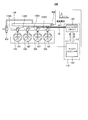
- 1 is a diagram showing an example of the overall configuration of a fuel injection system for an internal combustion engine to which the present invention is applied. It is a block diagram showing an example of an internal configuration of a fuel injection control device concerning one embodiment of the present invention.
- 5 is a flowchart showing an example of a procedure of a process (drive prohibition setting diagnosis) for determining the normality of a fuel injection cut function of the fuel injection control device according to the embodiment of the present invention.
- 6 is a flowchart showing an example of a procedure of a process (drive permission setting diagnosis) for determining the normality of a fuel injection cut function of the fuel injection control device according to the embodiment of the present invention.
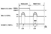
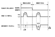
- 6 is a timing chart when an abnormality occurs in the drive prohibition setting of the fuel injection cut function according to the embodiment of the present invention.
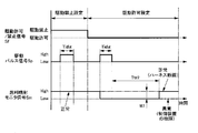
- 6 is a timing chart when the drive prohibition setting of the fuel injection cut function according to the embodiment of the present invention functions normally and an abnormality occurs in the drive permission setting of the fuel injection cut function.
- 6 is a timing chart when the drive prohibition setting and the drive permission setting of the fuel injection cut function according to the embodiment of the present invention function normally.
- Embodiment> [Overall configuration of fuel injection system] First, the outline of a fuel injection system of an internal combustion engine to which the present invention is applied will be described with reference to FIG.
- FIG. 1 shows an example of the overall configuration of a fuel injection system for an internal combustion engine to which the present invention is applied.
- the fuel injection system 100 is an example in which the present invention is applied to a cylinder direct injection engine (an example of an internal combustion engine), but the present invention is not limited to this example.
- the in-cylinder direct injection type engine may be simply referred to as “engine”.
- the fuel injection system 100 includes four injectors (fuel injection valves) 170A to 170D and a fuel injection control device 110 (an example of a control device). Each of the injectors 170A to 170D and the fuel injection control device 110 are connected by the wire harness 10.
- the in-cylinder direct injection type engine shown in FIG. 1 includes four cylinders 108 (engine cylinders). In the following description, the injectors 170A to 170D will be referred to as "injectors 170" if they are not distinguished.
- the fuel injection control device 110 is a control device for a vehicle that controls the operation of the injector 170.
- the injector 170 is an example of an actuator.
- Injectors 170A to 170D are installed in each cylinder 108 of the fuel injection system 100 so that atomized fuel is directly injected into the combustion chamber 107 from the injection holes.
- the fuel is boosted by the fuel pump 106, delivered to the fuel pipe 105, and delivered to the injectors 170A to 170D through the fuel pipe 105.
- a pressure sensor 102 that measures the fuel pressure in the fuel pipe 105 is installed at one end of the fuel pipe 105. The fuel pressure varies depending on the balance between the flow rate of the fuel discharged by the fuel pump 106 and the injection amount of the fuel injected by the injector 170 into each combustion chamber 107. Based on the measurement result of the pressure sensor 102, the discharge amount of fuel from the fuel pump 106 is controlled with a predetermined pressure as a target value.
- the fuel injection of the injectors 170A to 170D is controlled by the pulse width of the drive pulse signal sent from the microcomputer 120 of the fuel injection control device 110 (hereinafter referred to as "injection pulse width"). That is, the injection amount of the injected fuel is determined based on the length of the injection pulse width.
- the command of the injection pulse width determined by the microcomputer 120 is input to the injector driver 140 provided for each injector 170.
- the fuel injection control device 110 for example, an electronic control unit (ECU) mounted on an automobile is used. The detailed configuration of the fuel injection control device 110 will be described later.
- the injector driver 140 determines the waveform of the drive current (sometimes abbreviated as “current”) based on a command from the microcomputer 120, and causes the injector 170 to drive the drive current having the above waveform for a time period based on the injection pulse width. To supply.
- the injector driver 140 may be mounted as a component or board integrated with the microcomputer 120.
- the microcomputer 120 fetches a signal indicating the state of the engine from various sensors (not shown), and calculates an injection pulse width and an injection timing for controlling the injection amount injected from the injector 170 according to the operating condition of the engine. .. Further, the microcomputer 120 is equipped with an A/D converter and an I/O port for taking in signals from various sensors.
- the drive pulse signal output from the microcomputer 120 is input to the injector driver 140 via the signal line 111.
- the injector driver 140 controls the voltage applied to the coil 171 (see FIG. 2) of the injector 170 and supplies a current to the coil 171.
- the microcomputer 120 communicates with the injector driver 140 via the communication line 112. Through the communication line 112, the microcomputer 120 can switch the drive current generated by the injector driver 140 according to the pressure of the fuel supplied to the injector 170 and the operating conditions, and can change the set values of the current and time.
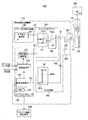
- FIG. 2 is a block diagram showing an internal configuration example of the fuel injection control device 110.
- the fuel injection system 100 includes a fuel injection control device 110 and an injector 170 connected to a battery power supply 180.
- the fuel injection control device 110 has a function of generating and outputting a fuel injection signal Si (driving current) to be supplied to the injector 170.
- the fuel injection control device 110 includes a microcomputer 120, a driver output inhibition device 130, an injector driver 140, an output terminal 150, and a monitor circuit 160.
- the microcomputer 120 sends a drive pulse signal Sp to the injector driver 140 and sends a command to the injector driver 140 to either allow or disallow the injector 170. Further, the fuel injection monitor signal Sm is input from the monitor circuit 160 to the microcomputer 120.
- the microcomputer 120 includes a diagnosis execution unit 121, a fuel injection control unit 122, a signal monitoring unit 123, and a memory 124.
- the fuel injection control unit 122 controls the operation of the injector driver 140 by transmitting the drive pulse signal Sp to the injector driver 140 based on the command of the diagnosis execution unit 121.
- the signal monitoring unit 123 monitors (receives) the fuel injection monitor signal Sm input from the monitor circuit 160 and detects the signal level thereof. Then, the signal monitoring unit 123 sends the information on the signal level of the fuel injection monitor signal Sm to the diagnosis executing unit 121.
- the diagnosis execution unit 121 activates the function of diagnosing the fuel injection cut function when the ignition switch signal indicating the state of the ignition switch received from the outside is ON and the engine speed is 0 rpm, and diagnoses the fuel injection cut function. Execute. Then, the diagnosis execution unit 121 controls the driver output inhibition device 130 and the injector driver 140 based on the signal level of the fuel injection monitor signal Sm received from the signal monitoring unit 123.
- the fuel injection cut function is described as an example of the fail safe function, but the present invention can be applied to diagnosis of other fail safe functions such as the ignition control cut function and the throttle fixed opening setting function.
- the memory 124 is a volatile memory such as a RAM (Random Access Memory) or a non-volatile memory such as a ROM (Read Only Memory).
- a control program executed by a processor (not shown) included in the microcomputer is recorded in the memory 124.
- the memory 124 also stores information such as the set time Ttf, the first set time Ttr1, and the second set time Ttr2 (see FIGS. 10 and 11 described later).
- the function of each block of the microcomputer 120 is realized by the processor executing the control program of the memory 124.
- a semiconductor memory or the like can be used as the memory 124.
- the driver output inhibition device 130 based on a command from the microcomputer 120, outputs a signal (drive permission/prohibition signal Sf) of a drive permission setting for permitting driving of the injector 170 or a drive inhibition setting for prohibiting driving of the actuator 170.
- An output prohibition calculation unit 131 for transmitting to the driver 140 is provided. Normally, the output prohibition calculation unit 131 outputs the drive permission/prohibition signal Sf set as the drive permission after the engine is started.
- the injector driver 140 supplies the fuel injection signal Si to the injector 170 via the output terminal 150 provided between the injector 170 and the injector 170 based on the drive pulse signal Sp.
- the injector driver 140 includes a drive control unit 141 and a drive circuit unit 142.
- the drive control unit 141 has an AND circuit 141a, and an inverted signal obtained by inverting the drive permission/prohibition signal Sf output from the output prohibition calculation unit 131 and a drive pulse signal Sp output from the fuel injection control unit 122.
- the drive circuit unit 142 supplies the fuel injection signal Si (drive current) to the coil 171 (for example, solenoid) based on the logical product signal output from the drive control unit 141 to drive the injector 170.
- the drive circuit unit 142 is configured by a circuit including a transistor 142a (an example of a switching element) such as an FET or a bipolar transistor. In FIG. 2, one end of the transistor 142a is connected to the high voltage battery power supply 180 (high voltage power supply) via the coil 171, and the other end of the transistor 142a is connected to the ground potential. Further, a logical product signal from the logical product circuit 141a is input to the gate of the transistor 142a. When the logical product signal is ON, the transistor 142a is energized (ON).
- the transistor 142a When the transistor 142a is turned on, a drive current due to a high voltage (for example, 14 V) battery voltage (second voltage) flows to the ground potential side via the coil 171 of the injector 170. On the other hand, when the transistor 142a is turned off, electric charge is accumulated (charged) in the capacitor 163 by the drive current generated by the battery voltage.
- the injector driver 140 switches ON/OFF of the transistor 142a of the drive circuit unit 142 and supplies a desired drive current to the coil 171.
- the output terminal 150 is a measurement point provided at the output end of the fuel injection control device 110.
- the output terminal 150 supplies the fuel injection signal Si output from the injector driver 140 to the injector 170.
- the monitor circuit 160 (an example of a monitoring signal input unit) is a fuel injection monitor signal Sm (an example of a monitoring signal) obtained according to the potential of an output terminal 150 (measurement point) provided between the injector driver 140 and the injector 170. ) Is input to the signal monitoring unit 123 of the microcomputer 120.
- the monitor circuit 160 includes a low voltage power supply unit 161, a diode 162, and a capacitor 163.
- the low-voltage power supply unit 161 supplies a voltage (first voltage) lower than the battery voltage of the battery power supply 180, and a voltage at which the current flowing between the injector 170 and the injector driver 140 can be input to the microcomputer 120. Convert to a level.
- the low-voltage power supply unit 161 has resistance elements 161a and 161b, and the midpoint of connection between the resistance elements 161a and 161b is connected to the output terminal 150 via the diode 162.
- the diode 162 is connected in the forward direction between the connection terminal of the resistance elements 161a and 161b and the output terminal 150, and blocks the current flowing from the battery power supply 180 to the low-voltage power supply unit 161 via the injector 170.
- the capacitor 163 (an example of a capacitive element) is connected to the output terminal 150, and stores electric charge by using the current flowing through the output terminal 150.
- the capacitor 163 of the present embodiment is higher than the first voltage of the low-voltage power supply unit 161 supplied from the high-voltage power supply (battery power supply 180) to the drive circuit (injector driver 140) via the actuator (injector 170).
- the capacitor 163 is charged by the second voltage (battery voltage).
- the capacitor 163 is charged by the first voltage supplied from the low voltage power supply unit 161.
- the monitor circuit 160 inputs a signal corresponding to the amount of charge accumulated in the capacitor 163 to the signal monitoring unit 123 as the fuel injection monitor signal Sm.
- the monitor circuit 160 configured as described above does not charge the capacitive element (capacitor 163) when the drive current (fuel injection signal Si) is supplied from the drive circuit (injector driver 140). Further, the monitor circuit 160 performs charging with the second voltage when the drive current is not supplied from the drive circuit and when the second voltage (battery voltage) is applied from the high voltage power supply (battery power supply 180). In addition, the monitor circuit 160 performs charging with the first voltage (low voltage) of the low-voltage power supply unit 161 when the drive current is not supplied from the drive circuit and the second voltage is not applied from the high-voltage power supply. In this way, the monitor circuit 160 can obtain the above-described monitor signal (fuel injection monitor signal Sm) according to the amount of charge stored in the capacitive element.
- the diagnosis execution unit 121 of the microcomputer 120 outputs a drive prohibition signal to the engine start prohibiting device 190 when the diagnosis result of the injection fuel cut function is abnormal.
- the engine start prohibition device 190 is a device that prevents the engine from being started when the drive prohibition signal is received. For example, as the engine start prohibiting device 190, the signal level of the fuel injection signal Si is turned off (the fuel injection monitor signal Sm is high at the output terminal 150 of the fuel injection control device 110) or a means for supplying a signal that prohibits the starter motor. There is a means for supplying a signal having a voltage level).
- the microcomputer 120 monitors the fuel injection monitor signal Sm and determines that there is an abnormality in the injected fuel cut function, the microcomputer 120 cannot distinguish between a failure in the injected fuel cut function and a wiring abnormality between the injector driver 140 and the injector 170. Occurs.
- the fuel is fed from the time when the drive pulse signal Sp changes from the high voltage level to the low voltage level until a predetermined time (second setting time Ttr2).
- a configuration is provided to determine whether the voltage of the injection monitor signal Sm changes by a predetermined voltage value or more. Then, when the voltage of the fuel injection monitor signal Sm does not change by the predetermined voltage value or more, it is determined that the fail-safe function of the fuel injection control device 110 has failed, and when it changes by the predetermined voltage value or more, the injector driver 140 and the injector 170 are connected. It is determined that the wiring that connects
- the wiring between the injector driver 140 and the injector 170 includes the signal wire from the output end of the injector driver 140 to the output terminal 150 and the wire harness 10 from the output terminal 150 to the injector 170.
- disconnection abnormality of the wire harness 10 is given, but the disconnection abnormality of the signal line from the output end of the injector driver 140 to the output terminal 150 is not excluded.
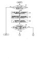
- FIG. 3 is a flowchart (1) showing an example of a procedure of processing for determining the normality of the fuel injection cut function of the fuel injection control device 110.
- FIG. 4 is a flowchart (2) showing an example of a procedure of processing for determining the normality of the fuel injection cut function of the fuel injection control device 110.
- FIG. 3 shows a procedure of drive prohibition setting diagnosis
- FIG. 4 shows a procedure of drive permission setting diagnosis.
- the flowcharts of FIGS. 3 and 4 will be described with reference to the timing charts and signal waveforms of FIGS. 5 to 11.
- the processing steps of the flowcharts of FIGS. 3 and 4 are realized by a processor (not shown) included in the microcomputer 120 executing a control program recorded in the memory 124.
- 5 to 8 show the drive pulse signal Sp input from the fuel injection control unit 122 to the injector driver 140, the drive permission/prohibition signal Sf input to the injector driver 140 from the output prohibition calculation unit 131, and the injector driver 140.
- 5 shows the timing of the fuel injection monitor signal Sm when the signal monitor 123 in the microcomputer 120 monitors the fuel injection signal Si between the injector 170 and the injector 170.
- the level of the drive permission/prohibition signal Sf is set to the drive prohibition value (drive prohibition setting)
- the drive pulse signal Sp is output from the fuel injection control unit 122
- the drive permission/prohibition signal Sf This is an example of a case where the output result of the fuel injection monitor signal Sm is normal and abnormal when the level is set to the drive permission value (drive permission setting) and the drive pulse signal Sp is output from the fuel injection control unit 122. ..
- the abnormality diagnosis of the fuel injection cut function of the fuel injection control device 110 in the present embodiment includes a drive prohibition setting diagnosis and a drive permission setting diagnosis.
- the drive prohibition setting diagnosis will be described with reference to steps S1 to S5.
- step S1 the diagnostic execution unit 121 of the microcomputer 120 determines whether the ignition switch signal input from the outside is ON and the engine speed is 0 rpm. Then, when the ignition signal is ON and the engine speed is 0 rpm (YES in S1), the diagnosis execution unit 121 activates the function for diagnosing the fuel injection cut function (fuel injection cut function diagnosis), and the step Go to S2.
- the diagnosis execution unit 121 determines that the ignition switch signal is not ON or the engine speed is not 0 rpm (NO in S1), the procedure goes to the end step, the ignition switch signal is ON, and the engine speed is Wait until it reaches 0 rpm.
- the engine mounted on the vehicle is stopped (state before engine start).
- the abnormality diagnosis of the fuel injection cut function shown in FIG. 3 and FIG. 4 is performed during a short period until the ignition switch signal is turned on and the engine is started.
- the parking brake is applied, the shift lever is in the parking (P) or neutral (N) position, and the brake pedal is depressed by the driver.
- the present invention can also be applied to an engine mounted on a vehicle (so-called hybrid vehicle) that is driven by two powers of an engine and an electric motor.
- a certain time for example, 10 seconds
- a certain time elapses after the driver depresses the brake pedal to put the engine into a ready state by pressing a button to start the engine, or the accelerator pedal is pressed.
- the engine starts by stepping on.
- the lapse of this fixed time or the depression of the accelerator pedal serves as a trigger for turning on the ignition switch signal.
- step S2 the diagnosis execution unit 121 outputs the drive permission/prohibition signal Sf from the output prohibition calculation unit 131 of the driver output prohibition device 130 to the drive control unit 141 of the injector driver 140 (drive prohibition value). Control) so that it will be sent.
- the drive permission/prohibition signal Sf is set to the drive prohibition setting state. Therefore, if the fuel injection cut function is normal, the fuel injection signal Si output from the injector driver 140 remains at the high voltage level and remains unchanged (see FIG. 5), and fuel is not injected from the injector 170.
- the drive prohibition/prohibition signal Sf of the drive prohibition value is output from the output prohibition calculation unit 131 to the drive control unit 141 and the drive control unit 141 is set to the drive prohibition setting state, the process proceeds to step S3.
- step S3 the diagnosis execution unit 121 sets the fuel injection control unit 122 to send a square wave (see FIG. 9) as the drive pulse signal Sp to the drive control unit 141.
- the drive pulse signal Sp is supplied from the fuel injection control unit 122 to the drive control unit 141, the process proceeds to step S4.
- the drive pulse signal Sp will be described with reference to FIG.
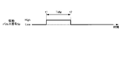
- FIG. 9 shows an example of the drive pulse signal Sp given to the injector driver 140.
- the drive setting period Tidig from the time t1 when the signal level of the drive pulse signal Sp is switched from Low (OFF) to High (ON) to the time t2 when it is switched from High to Low again drives the injector 170. It will be the set period.
- the output signal of the drive circuit section 142 of the injector driver 140 becomes a fuel injection signal Si for actually injecting fuel from the injector 170, and becomes a signal obtained by inverting the drive pulse signal Sp.
- the monitor circuit 160 outputs the signal level of the fuel injection signal Si as a monitoring signal (fuel injection monitor signal Sm) to the signal monitoring unit 123 of the microcomputer 120 according to the fuel injection signal Si output from the injector driver 140.
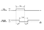
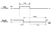
- FIG. 10 shows an example of a monitor signal for the drive pulse signal Sp given to the injector driver 140 and the fuel injection signal Si given to the injector 170.
- the drive period Todig1 from the predetermined set time Ttf of the fuel injection monitor signal Sm after the predetermined set time Ttf of the time t1 to the first set time Ttr1 of the time t2 corresponds to a period in which the injector 170 is driven. That is, when the fuel injection monitor signal Sm is at the low voltage level, fuel injection is performed.
- the waveform of the fuel injection monitor signal Sm similarly changes after a certain time delay from the waveform change of the drive pulse signal Si.
- the set time Ttf and the first set time Ttr1 are determined according to the response speed of the signal monitoring unit 123 to the input signal.
- step S4 the diagnosis execution unit 121 recognizes the low voltage level of the fuel injection monitor signal Sm, which is the monitoring signal of the fuel injection signal Si flowing between the injector driver 140 and the injector 170, in the signal monitoring unit 123. Wait for a possible set time Ttf (see FIG. 10). When the set time Ttf at which the signal monitoring unit 123 can recognize the low voltage level of the fuel injection monitor signal Sm has elapsed, the process proceeds to step S5.
- step S5 the diagnosis execution unit 121 determines that the drive pulse signal Sp supplied to the drive control unit 141 of the injector driver 140 in step S3 is the drive permission/prohibition signal Sf (drive prohibition) from the output prohibition calculation unit 131. It is determined whether the output is prohibited (whether the fuel injection signal Si is not output) by the value. Specifically, the diagnosis execution unit 121 determines whether or not the voltage value of the fuel injection monitor signal Sm input to the signal monitoring unit 123 has become equal to or lower than the first threshold value (for example, low voltage level).
- the first threshold value for example, low voltage level
- FIG. 5 is a timing chart when an abnormality occurs in the drive prohibition setting of the fuel injection cut function.
- the drive permission/prohibition signal Sf when the drive permission/prohibition signal Sf is set to the drive prohibition, the voltage value of the fuel injection monitor signal Sm changes to a low voltage level (first threshold value or less), and a square wave is generated. That is, the voltage of the fuel injection monitor signal Sm fluctuates by a predetermined width W1 or more from the voltage value at the time when the drive pulse signal Sp switches from OFF to ON.
- the diagnosis execution unit 121 determines that the drive prohibition setting of the fuel injection cut function is not functioning normally, that is, the fuel injection cut function of the fuel injection control device 110 (driver output prohibition device 130 or injector driver). 140) is abnormal. Then, the diagnosis execution unit 121 proceeds to step S16 (connector B), prohibits engine start, and ends the diagnosis process.
- the diagnosis execution unit 121 instructs the output prohibition calculation unit 131 to send the drive permission/prohibition signal Sf of the drive prohibition setting (drive prohibition value) to the drive control unit 141, and The fuel injection control unit 122 is instructed to send the drive pulse signal Sp to the drive control unit 141.
- the diagnosis execution unit 121 waits until the set time Ttf at which the low voltage level can be recognized by the fuel injection monitor signal Sm of the signal monitoring unit 123 elapses. When the low voltage level is detected after the set time Ttf has elapsed, the diagnosis execution unit 121 prohibits the engine start.
- step S5 if the low voltage level of the fuel injection monitor signal Sm is not detected by the signal monitoring unit 123 in step S5 (NO in S5), there are two possibilities. That is, when the drive prohibition setting of the fuel injection cut function operates normally and a low voltage level is not detected, and due to an abnormality in the injector 170 or a control component forming the fuel injection control device 110, the fuel injection monitor signal Sm is detected. Both possibilities if you did not detect the low voltage level. Therefore, the diagnosis execution unit 121 proceeds to step S6 (connector A) to instruct the output prohibition calculation unit 131 to set the drive permission, and based on the fuel injection monitor signal Sm, the fuel injection signal by the drive pulse signal Sp. Monitor Si.
- the control that configures the injector 170 and the fuel injection control device 110 is performed. It is possible to determine that the component is abnormal.
- Step S6 the drive permission setting diagnosis will be described with reference to steps S6 to S16.
- the drive permission/prohibition signal Sf is set to the drive permission value in the output prohibition calculation unit 131
- the drive pulse signal Sp is output from the fuel injection control unit 122
- the fuel injection signal Si is output.
- step S6 the diagnosis execution unit 121 sets the drive permission/prohibition signal Sf to the drive permission value (drive permission setting) from the output prohibition calculation unit 131 of the driver output prohibition device 130 to the drive control unit 141 of the injector driver 140. Control to send.
- the drive control unit 141 is set to the drive permission setting state, the process proceeds to step S7.
- step S7 the diagnostic execution part 121 sets the fuel injection control part 122 to send a square wave (see FIG. 9) as the drive pulse signal Sp to the drive control part 141, as in step S3.
- the drive pulse signal Sp is output from the fuel injection control unit 122 to the drive control unit 141, the process proceeds to step S8.
- step S8 the diagnosis execution unit 121 waits for a set time Ttf at which the signal monitoring unit 123 can recognize the low voltage level of the fuel injection monitor signal Sm (see FIG. 10).
- Ttf the time at which the low voltage level of the fuel injection monitor signal Sm can be recognized by the signal monitoring unit 123 has elapsed.
- step S9 the diagnosis execution unit 121 prohibits the drive pulse signal Sp supplied to the drive control unit 141 of the injector driver 140 in step S7 from being output by the drive permission/prohibition signal Sf from the output prohibition calculation unit 131. Instead, it is determined whether the output is permitted (whether the fuel injection signal Si is output). Specifically, the diagnosis execution unit 121 determines whether or not the voltage value of the fuel injection monitor signal Sm input to the signal monitoring unit 123 has become equal to or lower than the first threshold value (for example, low voltage level).
- the first threshold value for example, low voltage level
- FIG. 6 is a timing chart when the drive prohibition setting of the fuel injection cut function functions normally and an abnormality occurs in the drive permission setting of the fuel injection cut function.
- the voltage value of the fuel injection monitor signal Sm does not change to the low voltage level (first threshold value or less) when the drive permission/prohibition signal Sf is set to drive permission.
- the diagnosis execution unit 121 determines that the drive permission setting of the fuel injection cut function is not functioning normally, that is, the voltage value is changed due to an abnormality in the injector 170 or a control component forming the fuel injection control device 110. It is determined that it has not become less than or equal to the first threshold. Then, the diagnosis execution unit 121 proceeds to step S16, prohibits the engine start, and ends the diagnosis process.
- FIG. 7 is a timing chart when the drive prohibition setting and the drive permission setting of the fuel injection cut function function normally.
- the drive permission/prohibition signal Sf when the drive permission/prohibition signal Sf is set to drive permission, the voltage value of the fuel injection monitor signal Sm changes to a low voltage level (first threshold value or less), and a square wave is generated. In this case (YES in S9), it is possible that the drive permission setting of the fuel injection cut function is functioning normally, the wire harness 10 connecting the fuel injection control device 110 and the injector 170 is broken, or the injector driver 140 is out of order. There is a nature.
- the process proceeds to step S10.
- step S10 the diagnosis execution unit 121 waits for the first set time Ttr1 (see FIG. 10) at which the signal monitoring unit 123 can recognize the high voltage level of the fuel injection monitor signal Sm when normal.
- the process proceeds to step S11.
- the fuel injection cut function is determined to be normal, and the diagnostic process ends.
- the wire harness 10 connecting the fuel injection control device 110 and the injector 170 may have a disconnection abnormality or the injector driver 140. It is possible to determine that the failure of
- step S11 the diagnosis execution unit 121 determines that the drive pulse signal Sp supplied to the drive control unit 141 of the injector driver 140 in step S7 is the drive permission/prohibition signal Sf (drive permission) from the output prohibition calculation unit 131. Value) determines whether output is permitted (whether the fuel injection signal Si is output). Specifically, the diagnosis execution unit 121 determines whether or not the voltage value of the fuel injection monitor signal Sm input to the signal monitoring unit 123 is equal to or higher than the second threshold value (for example, high voltage level).
- the second threshold value for example, high voltage level
- the diagnosis execution unit 121 proceeds to step S14. .. In this case, the diagnosis execution unit 121 can detect the square wave output of the fuel injection monitor signal Sm with respect to the square wave input of the drive pulse signal Sp in the drive permission setting state. On the other hand, if the signal monitoring unit 123 does not detect that the voltage value of the fuel injection monitor signal Sm is equal to or higher than the second threshold value (NO in S11), the diagnosis executing unit 121 disconnects the wire harness 10. , Or there is a possibility of failure of the injector driver 140 and the like in the fuel injection control device 110, the process proceeds to step S12.
- FIG. 11 shows an example of the drive pulse signal Sp given to the injector driver 140 when the wire harness 10 is broken and the fuel injection monitor signal Sm given to the injector when the wire harness 10 is broken.
- the fuel injection monitor signal Sm changes from the low voltage level to the high voltage level from the time (time t2) when the drive pulse signal Sp changes from the high voltage level to the low voltage level as shown in FIG.
- the voltage of the fuel injection monitor signal Sm fluctuates by a predetermined width W1 or more from the voltage value at the time when the drive pulse signal Sp switches from on to off.
- the reason why the signal monitoring unit 123 recognizes the high voltage level of the fuel injection monitor signal Sm longer than in the normal state is that the power source for charging the capacitor 163 is switched from the battery power source 180 to the low voltage power source unit 161. .. That is, in a normal state, when the fuel injection signal Si is turned off, the capacitor 163 is charged by the high voltage (for example, 14 V) of the battery power supply 180 to output the high voltage level of the fuel injection monitor signal Sm. However, when the wire harness 10 is broken, the capacitor 163 is charged with a low voltage (for example, 3V) of the low voltage power supply unit 161 included in the monitor circuit 160, and a high voltage level is output.
- a low voltage for example, 3V
- the diagnosis execution unit 121 determines whether the wire harness 10 of the wire harness 10 is changed when the fuel injection monitor signal Sm changes after the second set time Ttr2 has passed after the drive pulse signal Sp has become the low voltage level. It is determined that disconnection (drive voltage started up with a delay) has occurred. On the other hand, if the fuel injection monitor signal Sm does not change even after the second set time Ttr2 has elapsed, the diagnosis execution unit 121 determines that the abnormality (the drive voltage does not rise) of the fuel injection control device 110 has occurred. Can be judged.
- the determination can be made by monitoring the fuel injection monitor signal Sm input to the signal monitoring unit 123.
- FIG. 8 is a timing chart when the drive prohibition setting of the fuel injection cut function normally functions and it is determined whether the wire harness 10 is broken or the fuel injection control device 110 is abnormal in the drive permission setting of the fuel injection cut function. ..
- the voltage value of the fuel injection monitor signal Sm becomes the second threshold value. If the above can be confirmed, it can be determined that the fuel injection control device 110 is normal (the wire harness 10 is broken), and if the voltage value does not change, the fuel injection control device 110 is abnormal.
- step S12 when it is not detected that the voltage value of the fuel injection monitor signal Sm is equal to or higher than the second threshold value (NO in S11), the diagnosis execution unit 121 causes the signal monitoring unit 123 to perform the diagnosis.
- a second set time Ttr2 (see FIG. 11) in which the high voltage level of the fuel injection monitor signal Sm can be recognized when the wire harness is disconnected is waited for. Then, when the second set time Ttr2 has elapsed, the process proceeds to step S13.
- step S13 the diagnosis execution unit 121 determines whether or not the signal monitoring unit 123 detects that the voltage value of the fuel injection monitor signal Sm has become equal to or higher than the second threshold value.
- the diagnosis execution unit 121 proceeds to step S15. ..
- the diagnosis executing unit 121 proceeds to step S16. ..
- step S14 when it is detected that the voltage value of the fuel injection monitor signal Sm has become equal to or higher than the second threshold value (YES in S11), the diagnosis execution unit 121 determines that the fuel in the drive permission setting state is present.
- the injection cut function is determined to be normal and the engine start is permitted. As a result, engine start is started by starting a starter motor (not shown). After the processing of step S14 ends, the diagnosis processing ends.
- the microcomputer 120 when the microcomputer 120 confirms the normal state in the diagnosis of the drive prohibition setting state of the fuel injection cut function (corresponding to NO in S5), it performs the diagnosis of the drive permission setting state. It has a function to migrate.
- the microcomputer 120 sends a square wave of the drive pulse signal Sp to the injector driver 140 and detects a square wave output from the fuel injection monitor signal Sm in the drive permission setting state (corresponding to YES in S9 and YES in S11). If it does, it has a function to allow the engine to start.
- step S15 when it is detected that the voltage value of the fuel injection monitor signal Sm has become equal to or higher than the second threshold value (YES in S13), the diagnosis execution unit 121 disconnects the wire harness 10 from the wire. Judge that there is and allow the engine to start. As a result, engine start is started by starting a starter motor (not shown). After the processing of step S15 ends, the diagnosis processing ends.
- the microcomputer 120 has a function of shifting to the drive permission setting diagnosis when it is confirmed that the drive prohibition setting diagnosis is normal (corresponding to NO in S5).
- the microcomputer 120 sends a square wave of the drive pulse signal Sp to the injector driver 140, and after confirming that the voltage value of the fuel injection monitor signal Sm becomes equal to or lower than the first threshold value (S9).
- the fuel injection monitor signal Sm at the normal time (first set time Ttr1), and detects that the voltage value of the fuel injection monitor signal Sm is the first threshold value or more. It has a function to do.
- the high voltage level recognition time (second time) of the fuel injection monitor signal Sm when the wire harness is disconnected (second time) After waiting for the set time Ttr2) of (1), when it is detected that the voltage value of the fuel injection monitor signal Sm is the second value or more (corresponding to YES in S13), a function of permitting the engine start is provided. ..
- step S16 when it is not detected that the voltage value of the fuel injection monitor signal Sm is equal to or higher than the second threshold value (NO in S13), the diagnosis execution unit 121 causes the fuel injection control device 110 to perform the diagnosis. It is determined that there is something wrong with the engine and the engine start is prohibited. As a result, engine starting by starting a starter motor (not shown) is prohibited. After the processing of step S16 ends, the diagnosis processing ends.
- the microcomputer 120 detects that the voltage value has become equal to or less than the first threshold value in the fuel injection monitor signal Sm in the drive prohibition setting diagnosis (corresponding to YES in S5). , Has a function to prohibit the start of the engine.
- the microcomputer 120 has a function of shifting to the drive permission setting diagnosis when it is confirmed in the drive prohibition setting diagnosis that it is normal (corresponding to NO in S5).
- the microcomputer 120 sends a square wave of the drive pulse signal Sp to the injector driver 140 and cannot confirm that the voltage value of the fuel injection monitor signal Sm is equal to or less than the first threshold value. (Corresponding to NO in S9), it is determined that the fuel injection control device 110 is in an abnormal state, and a function of prohibiting the engine start is provided.
- the microcomputer 120 sends a square wave of the drive pulse signal Sp to the injector driver 140, and after confirming that the voltage value of the fuel injection monitor signal Sm becomes the first threshold value or less (S9).
- the fuel injection monitor signal Sm at the normal time (first set time Ttr1), and detects that the voltage value of the fuel injection monitor signal Sm is the first threshold value or more. It has a function to do.
- the high voltage level recognition time (second time) of the fuel injection monitor signal Sm when the wire harness is disconnected second time
- Ttr2 the set time
- the control device that controls the actuator (injector 170) of the present embodiment supplies the drive current (fuel injection signal Si) to the actuator based on the drive pulse signal Sp.
- An injector driver 140 a control unit (microcomputer 120) for controlling the operation of the drive circuit by transmitting a drive pulse signal Sp, and a drive permission setting or actuator for permitting actuator drive based on a command from the control unit.
- a drive circuit output setting unit (driver output prohibiting device 130) for transmitting a drive prohibition setting signal for prohibiting the driving of the drive circuit to the drive circuit.
- control device inputs a monitor signal (fuel injection monitor signal Sm) obtained according to the potential between the drive circuit and the actuator (for example, the output terminal 150) to the monitor signal input unit (monitor circuit 160). Equipped with.
- the control unit sets the command of the fuel injection cut function to drive permission setting, switches the drive pulse signal Sp from on (high state) to off (low state), and elapses after the drive pulse signal Sp is switched off.
- the abnormality diagnosis in the drive permission setting state is performed based on the time (first set time Ttr1 or second set time Ttr2) and the state of the monitoring signal.
- the control unit sets the voltage of the monitoring signal (fuel injection monitor signal Sm) to the voltage of the monitoring signal (fuel injection monitor signal Sm) after the drive pulse signal Sp is switched from ON to OFF until the first set time Ttr1 based on the response performance of the control unit elapses.
- the drive pulse signal Sp is turned on by using the monitoring signal obtained according to the potential between the drive circuit (injector driver 140) and the actuator (injector 170).
- the drive function of the actuator when switched off can be diagnosed. Therefore, even if the drive circuit fails, it is possible to perform abnormality diagnosis in the drive permission setting state.
- the drive permission setting diagnosis it is possible to detect an abnormality in which the drive current to the actuator is not switched off even though the drive pulse signal Sp is switched from on to off.
- the voltage of the monitor signal fluctuates by a predetermined width W1 (see FIGS. 5 and 8) from the voltage value at the time when the drive pulse signal Sp is switched off.
- a control unit microcomputer 120
- determines that the wiring for example, the wire harness 10) connecting the drive circuit (injector driver 140) and the actuator (injector 170) is broken.
- the drive current is not switched off based on the state of the monitoring signal after the elapse of the second set time Ttr2 longer than the first set time Ttr1 based on the response performance of the control unit. It is possible to determine the cause of. For example, when the voltage of the monitor signal fluctuates by a predetermined width W1 or more from the voltage value at the time when the drive pulse signal Sp is switched off after the second set time Ttr2 has passed, the drive circuit and the actuator are connected. It can be determined that the wiring (for example, the wire harness 10) is broken.
- the predetermined width W1 may be different when the voltage of the fuel injection monitor signal Sm switches from high to low and when the voltage of the fuel injection monitor signal Sm switches from low to high.
- control unit performs abnormality diagnosis (drive permission setting diagnosis) before starting the internal combustion engine (engine) in which the actuator (injector 170) is installed, and the drive pulse signal Sp changes from ON to OFF.
- the voltage of the monitoring signal fuel injection monitor signal Sm
- time t2 the voltage of the monitoring signal is equal to or more than the predetermined width W1 from the voltage value at the time when the drive pulse signal Sp is switched off (time t2). If it fluctuates, the start of the internal combustion engine is permitted.
- the abnormality diagnosis before the internal combustion engine is started (drive permission setting diagnosis) is performed, and after the second set time Ttr2 has elapsed, the voltage of the monitoring signal changes to the value at the time when the drive pulse signal Sp is turned off.
- the voltage value fluctuates by a predetermined width W1 or more, the start of the internal combustion engine can be permitted. That is, it is possible to determine whether or not the failsafe function is abnormal before the engine is started, and to distinguish it from the abnormality of the control device. Therefore, appropriate measures can be taken for each abnormality.
- the second longer than the first set time Ttr1 after the drive pulse signal Sp is switched from the on (high state) to the off (low state).
- the set time Ttr2 of Eq. (3) elapses, the voltage of the monitoring signal (fuel injection monitor signal Sm) varies from the voltage value at the time when the drive pulse signal Sp is turned off by a predetermined width W1 or more (see FIGS. 5 and 8). If not, a control unit (microcomputer 120) that determines that the control device (fuel injection control device 110) is abnormal is provided.
- the drive current is not switched off based on the state of the monitoring signal after the elapse of the second set time Ttr2 longer than the first set time Ttr1 based on the response performance of the control unit. It is possible to determine the cause of. For example, if the voltage of the monitoring signal does not fluctuate by the predetermined width W1 or more from the voltage value at the time when the drive pulse signal Sp is switched off after the second set time Ttr2 has passed, it is determined that the control device has an abnormality. I can judge.
- control unit performs abnormality diagnosis (drive permission setting diagnosis) before starting the internal combustion engine (engine) in which the actuator (injector 170) is installed, and the drive pulse signal Sp changes from ON to OFF. Even if the second set time Ttr2 elapses after the switch to, the voltage of the monitoring signal (fuel injection monitor signal Sm) is changed from the voltage value at the time (time t2) when the drive pulse signal Sp is turned off to the predetermined width W1. If it does not fluctuate above, the start of the internal combustion engine is prohibited.
- abnormality diagnosis drive permission setting diagnosis
- the abnormality diagnosis (drive permission setting diagnosis) is performed before the internal combustion engine is started, and after the second set time Ttr2 has elapsed, the voltage of the monitoring signal changes to the value at the time when the drive pulse signal Sp is turned off. If the voltage value does not vary by the predetermined width W1 or more, it can be determined that the control device has an abnormality. That is, it is possible to determine whether or not the failsafe function is abnormal before the engine is started, and to distinguish it from the abnormality of the control device. Therefore, appropriate measures can be taken for each abnormality. For example, when the fuel injection cut function (fuel injection control device 110) fails, there is no fail-safe and safety cannot be ensured, so measures are taken to prevent the engine from starting.
- control unit sets the drive prohibition setting to the command output to the drive circuit output setting unit (driver output prohibition device 130) and turns on the drive pulse signal Sp to drive the drive circuit.
- the abnormality diagnosis is performed in the prohibition setting state, and the abnormality diagnosis in the drive prohibition setting state and the abnormality diagnosis in the drive permission setting state are performed before the internal combustion engine is started.
- both drive prohibition setting diagnosis and drive prohibition setting of the fail-safe function can be performed.
- control unit performs the abnormality diagnosis in the drive prohibition setting state, and when no abnormality is detected in the abnormality diagnosis in the drive prohibition setting state (NO in S5), the abnormality in the drive permission setting state is performed. Make a diagnosis.
- the drive permission diagnosis can be performed on the assumption that the actuator can be surely prohibited from being driven. , The concept of fail safe.
- the drive circuit output setting unit (driver output prohibition device 131) outputs a drive prohibition setting signal ( A command for outputting the drive permission/prohibition signal Sf) is output.
- a drive prohibition setting signal A command for outputting the drive permission/prohibition signal Sf
- the control unit does not turn on the drive pulse signal Sp transmitted to the drive circuit (injector driver 140) when it determines that the control device has an abnormality. As a result, the start of the internal combustion engine can be reliably prohibited.
- control unit determines that the control device has an abnormality, it sends a start prohibition signal for prohibiting the start of the internal combustion engine to the drive prohibition device (engine start prohibition device 190) that prohibits the start of the internal combustion engine. Output.
- the drive circuit output setting unit driver output prohibiting device 131
- the start of the internal combustion engine can be prohibited by means other than the control device.
- the above-described embodiment is a detailed and specific description of the configuration of the fuel injection control device 110 in order to explain the present invention in an easy-to-understand manner, and is not necessarily limited to one including all the components described. Further, it is possible to add, delete, or replace other components with respect to a part of the configuration of one embodiment. Further, the above-described respective configurations, functions, processing units, and the like may be realized by hardware by partially or entirely designing them with an integrated circuit, for example.
- the time constant of the monitor circuit 160 is shortened (for example, the capacitance of the capacitor 163 is reduced), or the power supply voltage (3 V in FIG. 2) of the stop voltage power supply unit 161 is set to a higher voltage, so that the capacitor 163 has a higher voltage.
- the charging speed may be increased.
- the time from when the drive pulse signal Sp switches from the high voltage level to the low voltage level until the fuel injection monitor signal Sm changes from the low voltage level to the high voltage level (the second set time Ttr2 in FIG. 11). ) Can be shortened. Therefore, it is possible to shorten the diagnosis time of the fail-safe function and shorten the time from the start of diagnosis to the driving of the actuator.
- Fuel injection system 110... Fuel injection control device, 120... Microcomputer, 121... Diagnostic execution unit, 122... Fuel injection control unit, 123... Signal monitoring unit, 130... Driver output prohibition device, 131... Output prohibition calculation unit , 140... Injector driver, 141... Drive control section, 142... Drive circuit section, 150... Output terminal, 160... Monitor circuit, 161... Low voltage power supply section, 162... Diode, 163... Capacitor, 170... Injector, 171... Coil , 180... Battery power
Landscapes
- Engineering & Computer Science (AREA)
- Chemical & Material Sciences (AREA)
- Combustion & Propulsion (AREA)
- Mechanical Engineering (AREA)
- General Engineering & Computer Science (AREA)
- Electrical Control Of Air Or Fuel Supplied To Internal-Combustion Engine (AREA)
- Combined Controls Of Internal Combustion Engines (AREA)
Abstract
燃料噴射弁等のアクチュエータを駆動する駆動回路が故障した場合でも、駆動許可設定状態における異常診断を実施可能とする。そのため本発明の一態様のアクチュエータを制御する制御装置は、駆動回路出力設定部に出力する指令を駆動許可設定とするとともに、駆動パルス信号をオンからオフに切り替えて、駆動パルス信号がオフに切り替わってから経過した時間と、駆動電流を出力する駆動回路とアクチュエータとの間の電位に応じて得られる監視信号の状態とに基づいて、駆動許可設定状態における異常診断を行う。
Description
本発明は、アクチュエータを制御する制御装置に係り、例えば内燃機関の燃焼室に燃料を供給する燃料噴射弁(インジェクタ)を制御する技術に関する。
内燃機関を制御する制御装置においては、内燃機関のトルク(以下「機関トルク」と称する。)に影響を及ぼす機構部品や制御部品の異常/故障を検出した時、操縦者に内燃機関の異常を通知すると共に、燃料噴射カット機能、点火制御カット機能、スロットル固定開度設定機能等のフェイルセーフ機能を実行している。しかしながら、内燃機関がフェイルセーフ機能を必要とする場合、仮にフェイルセーフ機能が動作しないと、異常な機関トルクが発生する可能性がある。このため、フェイルセーフ機能が正常に機能するかどうかを確認することが必要となる。
例えば、特許文献1には、内燃機関始動前に、燃料噴射カット機能(フェイルセーフ機能)を診断する診断期間を設定し、燃料噴射カット機能の診断期間に駆動許可/禁止信号をインジェクタドライバに出力し、その時のインジェクタドライバの動作状態監視用ポート(Disableポート)の信号状態を監視することで、燃料噴射カット機能の異常診断を実行することが示されている。
しかしながら、特許文献1においては、インジェクタドライバの動作状態監視用ポートの信号状態を監視しており、最終的なインジェクタドライバが出力する燃料噴射信号を監視していないため、インジェクタドライバの故障時にフェイルセーフ機能を正しく診断できない。それにより、フェイルセーフ機能が必要な場合に、駆動パルス出力を受けたインジェクタドライバを停止することができず、異常な機関トルクが発生する可能性がある。
本発明は、上記の状況に鑑みてなされたものであり、燃料噴射弁等のアクチュエータを駆動する駆動回路が故障した場合でも、駆動許可設定状態における異常診断を実施可能とすることを目的とする。
上記課題を解決するために、本発明の一態様のアクチュエータを制御する制御装置は、駆動パルス信号に基づきアクチュエータに駆動電流を供給する駆動回路と、駆動パルス信号を送信して駆動回路の動作を制御する制御部と、制御部からの指令に基づいて、アクチュエータの駆動を許可する駆動許可設定又はアクチュエータの駆動を禁止する駆動禁止設定の信号を駆動回路に送信する駆動回路出力設定部と、を備えたアクチュエータを制御する制御装置であって、上記駆動回路と上記アクチュエータとの間の電位に応じて得られる監視信号を上記制御部に入力する監視信号入力部を備える。
そして、上記制御部は、上記指令を駆動許可設定とするとともに、駆動パルス信号をオンからオフに切り替えて、駆動パルス信号がオフに切り替わってから経過した時間と監視信号の状態とに基づいて駆動許可設定状態における異常診断を行う。
そして、上記制御部は、上記指令を駆動許可設定とするとともに、駆動パルス信号をオンからオフに切り替えて、駆動パルス信号がオフに切り替わってから経過した時間と監視信号の状態とに基づいて駆動許可設定状態における異常診断を行う。
本発明の少なくとも一態様によれば、駆動回路とアクチュエータとの間の電位に応じて得られる監視信号を用いて、駆動許可設定状態における異常診断を行う。そのため、駆動回路が故障した場合でも、駆動許可設定状態における異常診断の実施が可能となる。
上記した以外の課題、構成及び効果は、以下の実施形態の説明により明らかにされる。
上記した以外の課題、構成及び効果は、以下の実施形態の説明により明らかにされる。
以下、本発明を実施するための形態(以下、「実施形態」と記述する)の例について、添付図面を参照して説明する。本明細書及び添付図面において実質的に同一の機能又は構成を有する構成要素については、同一の符号を付して重複する説明を省略する。
<1.一実施形態>[燃料噴射システムの全体構成]
始めに、図1を用いて、本発明が適用される内燃機関の燃料噴射システムの概略を説明する。
始めに、図1を用いて、本発明が適用される内燃機関の燃料噴射システムの概略を説明する。
図1は、本発明が適用される内燃機関の燃料噴射システムの全体構成例を示す。燃料噴射システム100は、本発明を筒内直接噴射式エンジン(内燃機関の一例)に適用した例であるが、本発明はこの例に限らない。本明細書において、筒内直接噴射式エンジンを単に「エンジン」と称することがある。
燃料噴射システム100は、図1に示すように、4つのインジェクタ(燃料噴射弁)170A~170D、及び燃料噴射制御装置110(制御装置の一例)とで構成される。インジェクタ170A~170Dの各々と燃料噴射制御装置110は、ワイヤーハーネス10によって接続されている。図1に示す筒内直接噴射式エンジンは、4つの気筒108(エンジンシリンダ)を備える。以下の説明において、インジェクタ170A乃至170Dを区別しない場合には、「インジェクタ170」と称する。燃料噴射制御装置110は、インジェクタ170の動作を制御する車両用の制御装置である。インジェクタ170は、アクチュエータの一例である。
燃料噴射システム100の各気筒108には、インジェクタ170A乃至170Dが、噴射孔から霧状の燃料が燃焼室107に直接噴射されるように設置されている。燃料は、燃料ポンプ106によって昇圧されて燃料配管105に送出され、燃料配管105を通じてインジェクタ170A乃至170Dに配送される。燃料配管105の一端部には、燃料配管105内の燃料圧力を測定する圧力センサ102が設置されている。燃料圧力は、燃料ポンプ106によって吐出された燃料の流量と、インジェクタ170によって各燃焼室107内に噴射された燃料の噴射量とのバランスによって変動する。圧力センサ102の測定結果に基づいて、所定の圧力を目標値として燃料ポンプ106からの燃料の吐出量が制御される。
インジェクタ170A乃至170Dの燃料の噴射は、燃料噴射制御装置110のマイクロコンピュータ120から送出される駆動パルス信号のパルス幅(以下「噴射パルス幅」と称する。)によって制御されている。すなわち、噴射される燃料の噴射量は、噴射パルス幅の長さに基づいて決定される。このマイクロコンピュータ120で決定された噴射パルス幅の指令は、インジェクタ170ごとに設けられたインジェクタドライバ140に入力される。燃料噴射制御装置110には、例えば自動車に搭載される電子制御ユニット(ECU:Electronic Control Unit)が使用される。燃料噴射制御装置110の詳細な構成については後述する。
インジェクタドライバ140は、マイクロコンピュータ120からの指令に基づいて駆動電流(「電流」と略称することがある。)の波形を決定し、上記噴射パルス幅に基づく時間だけインジェクタ170に上記波形の駆動電流を供給する。なお、インジェクタドライバ140は、マイクロコンピュータ120と一体の部品や基板として実装されている場合もある。
ここで、インジェクタ170及び燃料噴射制御装置110の構成と基本的な動作を説明する。
マイクロコンピュータ120は、エンジンの状態を示す信号を各種センサ(図示略)から取り込み、エンジンの運転条件に応じてインジェクタ170から噴射する噴射量を制御するための噴射パルス幅や噴射タイミングの演算を行う。また、マイクロコンピュータ120には、各種センサからの信号を取り込むためのA/D変換器とI/Oポートが備えられている。
マイクロコンピュータ120は、エンジンの状態を示す信号を各種センサ(図示略)から取り込み、エンジンの運転条件に応じてインジェクタ170から噴射する噴射量を制御するための噴射パルス幅や噴射タイミングの演算を行う。また、マイクロコンピュータ120には、各種センサからの信号を取り込むためのA/D変換器とI/Oポートが備えられている。
マイクロコンピュータ120より出力された駆動パルス信号は、信号線111を通してインジェクタドライバ140に入力される。インジェクタドライバ140は、インジェクタ170のコイル171(図2参照)に印加する電圧を制御し、コイル171に電流を供給する。マイクロコンピュータ120は、通信ライン112を介してインジェクタドライバ140と通信を行っている。マイクロコンピュータ120は、通信ライン112を通じて、インジェクタ170に供給する燃料の圧力や運転条件によってインジェクタドライバ140で生成する駆動電流を切り替えることや、電流及び時間の設定値を変更することが可能である。
[燃料噴射制御装置の構成]
次に、本発明の一実施形態に係る燃料噴射システム100が備える燃料噴射制御装置110の構成について詳述する。
次に、本発明の一実施形態に係る燃料噴射システム100が備える燃料噴射制御装置110の構成について詳述する。
図2は、燃料噴射制御装置110の内部構成例を示したブロック図である。図2において、燃料噴射システム100は、燃料噴射制御装置110と、バッテリ電源180に接続されるインジェクタ170とから構成される。燃料噴射制御装置110は、インジェクタ170に供給する燃料噴射信号Si(駆動電流)を生成して出力する機能を備えている。
燃料噴射制御装置110は、マイクロコンピュータ120、ドライバ出力禁止装置130、インジェクタドライバ140、出力端子150、及びモニタ回路160を備える。
マイクロコンピュータ120は、インジェクタドライバ140に駆動パルス信号Spを送信するとともに、インジェクタドライバ140にインジェクタ170の駆動許可又は駆動禁止のいずれかの指令を送信する。また、マイクロコンピュータ120には、モニタ回路160から燃料噴射モニタ信号Smが入力される。マイクロコンピュータ120は、診断実行部121、燃料噴射制御部122、信号監視部123、及びメモリ124により構成される。
燃料噴射制御部122は、診断実行部121の指令に基づいて、インジェクタドライバ140に駆動パルス信号Spを送信してインジェクタドライバ140の動作を制御する。
信号監視部123は、モニタ回路160から入力される燃料噴射モニタ信号Smを監視(受信)し、その信号レベルを検出する。そして、信号監視部123は、燃料噴射モニタ信号Smの信号レベルの情報を診断実行部121へ送る。
診断実行部121は、外部から受信したイグニッションスイッチの状態を示すイグニッションスイッチ信号がON、且つエンジン回転数が0rpmのとき、燃料噴射カット機能を診断する機能を起動し、燃料噴射カット機能の診断を実行する。そして、診断実行部121は、信号監視部123から受信する燃料噴射モニタ信号Smの信号レベルに基づいて、ドライバ出力禁止装置130及びインジェクタドライバ140を制御する。本実施形態では、フェイルセーフ機能として燃料噴射カット機能を例に説明するが、本発明は、点火制御カット機能、スロットル固定開度設定機能など他のフェイルセーフ機能の診断にも適用可能である。
メモリ124は、RAM(Random Access Memory)等の揮発性のメモリ、又はROM(Read Only Memory)等の不揮発性のメモリである。メモリ124には、マイクロコンピュータが備えるプロセッサ(図示略)により実行される制御プログラムが記録されている。
また、メモリ124には、例えば、設定時間Ttf、第1の設定時間Ttr1、及び第2の設定時間Ttr2(後述する図10、図11参照)などの情報が記録されている。マイクロコンピュータ120の各ブロックの機能は、プロセッサがメモリ124の制御プロググラムを実行することにより実現される。このメモリ124には、半導体メモリ等を用いることができる。
また、メモリ124には、例えば、設定時間Ttf、第1の設定時間Ttr1、及び第2の設定時間Ttr2(後述する図10、図11参照)などの情報が記録されている。マイクロコンピュータ120の各ブロックの機能は、プロセッサがメモリ124の制御プロググラムを実行することにより実現される。このメモリ124には、半導体メモリ等を用いることができる。
ドライバ出力禁止装置130は、マイクロコンピュータ120からの指令に基づいて、インジェクタ170の駆動を許可する駆動許可設定又はアクチュエータ170の駆動を禁止する駆動禁止設定の信号(駆動許可/禁止信号Sf)をインジェクタドライバ140に送信する出力禁止演算部131を備える。通常、出力禁止演算部131は、エンジン始動後、駆動許可設定とされた駆動許可/禁止信号Sfを出力する。
インジェクタドライバ140は、駆動パルス信号Spに基づきインジェクタ170との間に設けられた出力端子150を介してインジェクタ170に燃料噴射信号Siを供給する。インジェクタドライバ140は、駆動制御部141と、駆動回路部142により構成される。
駆動制御部141は、論理積回路141aを有し、出力禁止演算部131から出力される駆動許可/禁止信号Sfを反転させた反転信号と、燃料噴射制御部122から出力される駆動パルス信号Spとの論理積をとった論理積信号を、駆動制御部141へ出力する。
論理積回路141aは、出力禁止演算部131からの駆動許可/禁止信号Sfが駆動禁止設定である場合には、燃料噴射制御部122からの駆動パルス信号Spがオンであっても論理積信号“0”を出力し、インジェクタ170の駆動を禁止する。
論理積回路141aは、出力禁止演算部131からの駆動許可/禁止信号Sfが駆動禁止設定である場合には、燃料噴射制御部122からの駆動パルス信号Spがオンであっても論理積信号“0”を出力し、インジェクタ170の駆動を禁止する。
駆動回路部142は、駆動制御部141から出力される論理積信号に基づいて、燃料噴射信号Si(駆動電流)をコイル171(例えばソレノイド)に供給してインジェクタ170を駆動する。駆動回路部142は、例えばFETやバイポーラトランジスタなどのトランジスタ142a(スイッチング素子の一例)を含む回路により構成される。図2では、トランジスタ142aの一端はコイル171を介して高電圧のバッテリ電源180(高電圧電源)に接続し、トランジスタ142aの他端は接地電位に接続されている。また、トランジスタ142aのゲートには、論理積回路141aから論理積信号が入力される。論理積信号がONのとき、トランジスタ142aが通電(ON)する。
トランジスタ142aをONにすると、高電圧(例えば14V)のバッテリ電圧(第2の電圧)による駆動電流が、インジェクタ170のコイル171を介して接地電位側へ流れる。一方、トランジスタ142aをOFFにすると、バッテリ電圧による駆動電流によってキャパシタ163に電荷が蓄えられる(充電される)。インジェクタドライバ140は、駆動回路部142のトランジスタ142aのON/OFFを切り替え、コイル171に所望の駆動電流を供給する。
出力端子150は、燃料噴射制御装置110の出力端に設けられた計測点である。出力端子150は、インジェクタドライバ140が出力した燃料噴射信号Siをインジェクタ170へ供給する。
モニタ回路160(監視信号入力部の一例)は、インジェクタドライバ140とインジェクタ170との間に設けられた出力端子150(計測点)の電位に応じて得られる燃料噴射モニタ信号Sm(監視信号の一例)を、マイクロコンピュータ120の信号監視部123に入力するものである。モニタ回路160は、低電圧電源部161、ダイオード162、及びキャパシタ163により構成される。
低電圧電源部161は、バッテリ電源180のバッテリ電圧よりも低い電圧(第1の電圧)を供給するとともに、インジェクタ170とインジェクタドライバ140との間に流れる電流を、マイクロコンピュータ120に入力可能な電圧レベルに変換する。低電圧電源部161は、抵抗素子161a,161bを有し、抵抗素子161aと抵抗素子161bの接続中点は、ダイオード162を介して出力端子150と接続されている。ダイオード162は、抵抗素子161aと抵抗素子161bの接続中点と出力端子150との間に順方向に接続され、バッテリ電源180からインジェクタ170を介して低電圧電源部161へ流れ込む電流を遮断する。
また、キャパシタ163(容量素子の一例)は、出力端子150に接続されており、出力端子150を流れる電流を利用して電荷を蓄える。本実施形態のキャパシタ163は、高電圧電源(バッテリ電源180)からアクチュエータ(インジェクタ170)を介して駆動回路(インジェクタドライバ140)に供給される、低電圧電源部161の第1の電圧よりも高い第2の電圧(バッテリ電圧)によりキャパシタ163に充電を行う。または、キャパシタ163は、低電圧電源部161から供給される第1の電圧により充電を行う。そして、モニタ回路160は、キャパシタ163に蓄えられた電荷量に応じた信号を、燃料噴射モニタ信号Smとして信号監視部123へ入力する。
上記のように構成されたモニタ回路160は、駆動回路(インジェクタドライバ140)から駆動電流(燃料噴射信号Si)が供給されるときは容量素子(キャパシタ163)に充電を行わない。また、モニタ回路160は、駆動回路から駆動電流が供給されないとき且つ高電圧電源(バッテリ電源180)から第2の電圧(バッテリ電圧)が印加されるときは、第2の電圧により充電を行う。また、モニタ回路160は、駆動回路から駆動電流が供給されないとき且つ高電圧電源から第2の電圧が印加されないときは、低電圧電源部161の第1の電圧(低電圧)により充電を行う。このように、モニタ回路160は、上述した監視信号(燃料噴射モニタ信号Sm)を容量素子に蓄えられた電荷量に応じて得ることができる。
マイクロコンピュータ120の診断実行部121は、噴射燃料カット機能の診断結果が異常である場合には、エンジン始動禁止装置190へ駆動禁止信号を出力する。エンジン始動禁止装置190は、駆動禁止信号を受信すると、エンジンを始動させないようにする装置である。例えば、エンジン始動禁止装置190として、スタータモータの起動を禁止する信号を供給する手段や、燃料噴射制御装置110の出力端子150に燃料噴射信号Siの信号レベルがオフ(燃料噴射モニタ信号Smがハイ電圧レベル)となる信号を供給する手段などがある。
ところで、マイクロコンピュータ120は、燃料噴射モニタ信号Smを監視して噴射燃料カット機能に異常ありと判断した場合、噴射燃料カット機能の故障とインジェクタドライバ140とインジェクタ170間の配線異常とを区別できない課題が生じる。
その対策として、後述するように本実施形態では、駆動許可設定状態において、駆動パルス信号Spがハイ電圧レベルからロー電圧レベルになった時点から所定時間(第2の設定時間Ttr2)後までに燃料噴射モニタ信号Smの電圧が所定電圧値以上変化するかどうかを判定する構成を設けている。そして、燃料噴射モニタ信号Smの電圧が所定電圧値以上変化しない場合に、燃料噴射制御装置110のフェイルセーフ機能の故障と判定し、所定電圧値以上変化した場合に、インジェクタドライバ140とインジェクタ170とを接続する配線の異常と判定する。
なお、インジェクタドライバ140とインジェクタ170との間の配線には、インジェクタドライバ140の出力端から出力端子150までの信号線と、出力端子150からインジェクタ170までのワイヤーハーネス10がある。以降の説明において、断線異常として「ワイヤーハーネス10の断線異常」の例を挙げているが、インジェクタドライバ140の出力端から出力端子150までの信号線の断線異常を排除するものではない。
[燃料噴射カット機能の診断方法]
次に、本発明の一実施形態に係る燃料噴射制御装置110の燃料噴射カット機能が正常に動作しているかどうかを診断する具体的な診断方法について説明する。
次に、本発明の一実施形態に係る燃料噴射制御装置110の燃料噴射カット機能が正常に動作しているかどうかを診断する具体的な診断方法について説明する。
図3は、燃料噴射制御装置110の燃料噴射カット機能の正常性を判定する処理の手順例を示すフローチャート(1)である。図4は、燃料噴射制御装置110の燃料噴射カット機能の正常性を判定する処理の手順例を示すフローチャート(2)である。図3では駆動禁止設定診断の手順を示し、図4では駆動許可設定診断の手順を示す。図3及び図4のフローチャートについて、図5~図11のタイミングチャート及び信号波形を参照しながら説明する。図3及び図4のフローチャートの処理ステップは、マイクロコンピュータ120が備えるプロセッサ(図示略)が、メモリ124に記録された制御プログラムを実行することにより実現される。
図5~図8は、燃料噴射制御部122からインジェクタドライバ140に入力される駆動パルス信号Spと、出力禁止演算部131からインジェクタドライバ140に入力される駆動許可/禁止信号Sfと、インジェクタドライバ140とインジェクタ170との間の燃料噴射信号Siを、マイクロコンピュータ120内の信号監視部123で監視したときの燃料噴射モニタ信号Smのタイミングを示している。この図5~図8は、駆動許可/禁止信号Sfのレベルを駆動禁止値(駆動禁止設定)にし、燃料噴射制御部122から駆動パルス信号Spを出力した状態と、駆動許可/禁止信号Sfのレベルを駆動許可値(駆動許可設定)にし、燃料噴射制御部122から駆動パルス信号Spを出力した状態とにおいて、燃料噴射モニタ信号Smの出力結果が正常な場合と異常な場合のケース例である。
≪ステップS1≫
本実施形態における燃料噴射制御装置110の燃料噴射カット機能の異常診断は、駆動禁止設定診断と駆動許可設定診断から構成される。まず、ステップS1~S5を参照して駆動禁止設定診断について説明する。
本実施形態における燃料噴射制御装置110の燃料噴射カット機能の異常診断は、駆動禁止設定診断と駆動許可設定診断から構成される。まず、ステップS1~S5を参照して駆動禁止設定診断について説明する。
ステップS1において、マイクロコンピュータ120の診断実行部121は、外部から入力されるイグニッションスイッチ信号がONであり、且つエンジンの回転数が0rpmであるか否かを判定する。そして、診断実行部121は、イグニッション信号がON、且つエンジン回転数が0rpmである場合には(S1のYES)、燃料噴射カット機能を診断する機能(燃料噴射カット機能診断)を起動し、ステップS2に移行する。また、診断実行部121は、イグニッションスイッチ信号がONではない、又はエンジン回転数が0rpmではないと判定すると(S1のNO)、終了ステップに抜けて、イグニッションスイッチ信号がON、且つエンジン回転数が0rpmになるまで待機する。
エンジン回転数が0rpmであるとき、車両に搭載されたエンジンは停止中(エンジン始動前の状態)である。イグニッションスイッチ信号がONしてエンジンが始動するまでの僅かな期間に、図3及び図4に示す燃料噴射カット機能の異常診断が行われる。このとき、一般に、エンジンのみを搭載する車両の場合、パーキングブレーキがかかっているとともにシフトレバーはパーキング(P)又はニュートラル(N)の位置、ブレーキペダルは運転者によって踏み込まれた状態である。
なお、エンジンと電気モータの2つの動力によって走行する車両(いわゆるハイブリッド車)に搭載されたエンジンに対して本発明を適用することも可能である。例えばハイブリッド車の場合には、運転者がブレーキペダルを踏み込んだ状態でエンジンを始動可能状態にするボタンを押してエンジンをレディ状態とした後、一定時間(例えば10秒)が経過するか、アクセルペダルを踏み込むことによりエンジンが始動する。この一定時間の経過又はアクセルペダルの踏み込みが、イグニッションスイッチ信号がONするためのトリガとなる。
≪ステップS2≫
次に、ステップS2において、診断実行部121は、ドライバ出力禁止装置130の出力禁止演算部131からインジェクタドライバ140の駆動制御部141に対して、駆動許可/禁止信号Sfを駆動禁止値(駆動禁止設定)にして送るよう制御する。この状態で、マイクロコンピュータ120の燃料噴射制御部122からインジェクタドライバ140に駆動パルス信号Spが入力されても、駆動許可/禁止信号Sfが駆動禁止設定状態にセットされている。そのため、燃料噴射カット機能が正常であれば、インジェクタドライバ140から出力される燃料噴射信号Siはハイ電圧レベルのままで変化なく(図5参照)、インジェクタ170から燃料が噴射されることはない。出力禁止演算部131から駆動制御部141に対して駆動禁止値の駆動許可/禁止信号Sfが出力され、駆動制御部141を駆動禁止設定状態にセットすると、ステップS3に移行する。
次に、ステップS2において、診断実行部121は、ドライバ出力禁止装置130の出力禁止演算部131からインジェクタドライバ140の駆動制御部141に対して、駆動許可/禁止信号Sfを駆動禁止値(駆動禁止設定)にして送るよう制御する。この状態で、マイクロコンピュータ120の燃料噴射制御部122からインジェクタドライバ140に駆動パルス信号Spが入力されても、駆動許可/禁止信号Sfが駆動禁止設定状態にセットされている。そのため、燃料噴射カット機能が正常であれば、インジェクタドライバ140から出力される燃料噴射信号Siはハイ電圧レベルのままで変化なく(図5参照)、インジェクタ170から燃料が噴射されることはない。出力禁止演算部131から駆動制御部141に対して駆動禁止値の駆動許可/禁止信号Sfが出力され、駆動制御部141を駆動禁止設定状態にセットすると、ステップS3に移行する。
≪ステップS3≫
次に、ステップS3において、診断実行部121は、燃料噴射制御部122から駆動制御部141に対して駆動パルス信号Spとして方形波(図9参照)を送るよう設定を行う。燃料噴射制御部122から駆動制御部141に対して駆動パルス信号Spが供給されると、ステップS4に移行する。ここで、図9を参照して駆動パルス信号Spについて説明する。
次に、ステップS3において、診断実行部121は、燃料噴射制御部122から駆動制御部141に対して駆動パルス信号Spとして方形波(図9参照)を送るよう設定を行う。燃料噴射制御部122から駆動制御部141に対して駆動パルス信号Spが供給されると、ステップS4に移行する。ここで、図9を参照して駆動パルス信号Spについて説明する。
図9は、インジェクタドライバ140に与えられる駆動パルス信号Spの例を示す。図9において、駆動パルス信号Spの信号レベルが、Low(オフ)からHigh(オン)に切り替わった時刻t1から再びHighからLowに切り替わった時刻t2までの駆動設定期間Tidigが、インジェクタ170を駆動させる設定期間となる。インジェクタドライバ140の駆動回路部142の出力信号が、実際にインジェクタ170から燃料を噴射させるための燃料噴射信号Siとなり、駆動パルス信号Spを反転した信号となる。モニタ回路160は、インジェクタドライバ140から出力される燃料噴射信号Siに応じて、燃料噴射信号Siの信号レベルを監視信号(燃料噴射モニタ信号Sm)としてマイクロコンピュータ120の信号監視部123へ出力する。
図10は、インジェクタドライバ140に与えられる駆動パルス信号Spと、インジェクタ170に与えられる燃料噴射信号Siについてのモニタ信号の例を示す。図10において、燃料噴射モニタ信号Smの時刻t1の所定の設定時間Ttf後から時刻t2の第1の設定時間Ttr1後までの駆動期間Todig1が、インジェクタ170を駆動させる期間に相当する。すなわち、燃料噴射モニタ信号Smがロー電圧レベルのとき、燃料噴射が行われる。燃料噴射カット機能が正常な場合、駆動期間Todig1では、駆動パルス信号Siの波形変化から一定時間遅れて同じように燃料噴射モニタ信号Smの波形が変化する。これら設定時間Ttf及び第1の設定時間Ttr1は、信号監視部123の入力信号に対する応答速度に応じて決定される。
≪ステップS4≫
次に、ステップS4において、診断実行部121は、インジェクタドライバ140とインジェクタ170との間に流れる燃料噴射信号Siの監視信号である燃料噴射モニタ信号Smのロー電圧レベルを、信号監視部123で認識可能な設定時間Ttfを待つ(図10参照)。信号監視部123で燃料噴射モニタ信号Smのロー電圧レベルを認識可能な設定時間Ttfが経過したら、ステップS5に移行する。
次に、ステップS4において、診断実行部121は、インジェクタドライバ140とインジェクタ170との間に流れる燃料噴射信号Siの監視信号である燃料噴射モニタ信号Smのロー電圧レベルを、信号監視部123で認識可能な設定時間Ttfを待つ(図10参照)。信号監視部123で燃料噴射モニタ信号Smのロー電圧レベルを認識可能な設定時間Ttfが経過したら、ステップS5に移行する。
≪ステップS5≫
次に、ステップS5において、診断実行部121は、ステップS3でインジェクタドライバ140の駆動制御部141に供給された駆動パルス信号Spが、出力禁止演算部131からの駆動許可/禁止信号Sf(駆動禁止値)によって出力禁止されているか(燃料噴射信号Siが出力されていないか)を判定する。具体的には、診断実行部121は、信号監視部123に入力された燃料噴射モニタ信号Smの電圧値が第1の閾値以下(例えばロー電圧レベル)となったかどうかを判定する。
次に、ステップS5において、診断実行部121は、ステップS3でインジェクタドライバ140の駆動制御部141に供給された駆動パルス信号Spが、出力禁止演算部131からの駆動許可/禁止信号Sf(駆動禁止値)によって出力禁止されているか(燃料噴射信号Siが出力されていないか)を判定する。具体的には、診断実行部121は、信号監視部123に入力された燃料噴射モニタ信号Smの電圧値が第1の閾値以下(例えばロー電圧レベル)となったかどうかを判定する。
図5は、燃料噴射カット機能の駆動禁止設定において異常が発生した場合のタイミングチャートである。図5では、駆動許可/禁止信号Sfが駆動禁止設定の状態において、燃料噴射モニタ信号Smの電圧値がロー電圧レベル(第1の閾値以下)に変化し、方形波が発生している。すなわち、燃料噴射モニタ信号Smの電圧が、駆動パルス信号Spがオフからオンに切り替わった時点の電圧値から所定幅W1以上変動している。この場合(S5のYES)、診断実行部121は、燃料噴射カット機能の駆動禁止設定が正常に機能していない、つまり燃料噴射制御装置110の燃料噴射カット機能(ドライバ出力禁止装置130又はインジェクタドライバ140)が異常であると判定する。そして、診断実行部121は、ステップS16(結合子B)に移行し、エンジンの始動を禁止して診断処理を終了する。
このように、駆動禁止設定診断では、診断実行部121は、出力禁止演算部131に対し駆動制御部141へ駆動禁止設定(駆動禁止値)の駆動許可/禁止信号Sfを送る指示をし、且つ燃料噴射制御部122に対し駆動制御部141へ駆動パルス信号Spを送る指示をする。その後、診断実行部121は、信号監視部123の燃料噴射モニタ信号Smでロー電圧レベルを認識可能な設定時間Ttfが経過するのを待つ。そして、設定時間Ttfの経過後にロー電圧レベルが検出された場合には、診断実行部121は、エンジンの始動を禁止する。
一方、ステップS5において、信号監視部123で燃料噴射モニタ信号Smのロー電圧レベルが検出されない場合には(S5のNO)、2つの可能性が考えられる。すなわち、燃料噴射カット機能の駆動禁止設定が正常に動作してロー電圧レベルを検出しなかった場合と、インジェクタ170や燃料噴射制御装置110を構成する制御部品の異常によって、燃料噴射モニタ信号Smにおいてロー電圧レベルを検出しなかった場合の両方の可能性である。このため、診断実行部121は、ステップS6(結合子A)に移行して、出力禁止演算部131へ駆動許可設定を指令し、燃料噴射モニタ信号Smに基づいて駆動パルス信号Spによる燃料噴射信号Siを監視する。そして、燃料噴射信号Siの出力が検出されれば、燃料噴射カット機能は正常であると判定し、燃料噴射信号Siの出力が検出されなければ、インジェクタ170や燃料噴射制御装置110を構成する制御部品の異常と判定することが可能となる。
≪ステップS6≫
次に、ステップS6~S16を参照して駆動許可設定診断について説明する。ステップS6以降の処理ステップにより、出力禁止演算部131において駆動許可/禁止信号Sfを駆動許可値に設定し、燃料噴射制御部122から駆動パルス信号Spを出力し、燃料噴射信号Siが出力されるかを監視することで、燃料噴射カット機能の駆動許可設定状態の正常性を確認する。
次に、ステップS6~S16を参照して駆動許可設定診断について説明する。ステップS6以降の処理ステップにより、出力禁止演算部131において駆動許可/禁止信号Sfを駆動許可値に設定し、燃料噴射制御部122から駆動パルス信号Spを出力し、燃料噴射信号Siが出力されるかを監視することで、燃料噴射カット機能の駆動許可設定状態の正常性を確認する。
ステップS6において、診断実行部121は、ドライバ出力禁止装置130の出力禁止演算部131からインジェクタドライバ140の駆動制御部141に対して、駆動許可/禁止信号Sfを駆動許可値(駆動許可設定)にして送るよう制御する。駆動制御部141を駆動許可設定状態にセットすると、ステップS7に移行する。
≪ステップS7≫
次に、ステップS7において、診断実行部121はステップS3と同様に、燃料噴射制御部122から駆動制御部141に対して駆動パルス信号Spとして方形波(図9参照)を送るよう設定を行う。燃料噴射制御部122から駆動制御部141に対して駆動パルス信号Spが出力されると、ステップS8に移行する。
次に、ステップS7において、診断実行部121はステップS3と同様に、燃料噴射制御部122から駆動制御部141に対して駆動パルス信号Spとして方形波(図9参照)を送るよう設定を行う。燃料噴射制御部122から駆動制御部141に対して駆動パルス信号Spが出力されると、ステップS8に移行する。
≪ステップS8≫
次に、ステップS8において、診断実行部121は、燃料噴射モニタ信号Smのロー電圧レベルを、信号監視部123で認識可能な設定時間Ttfを待つ(図10参照)。信号監視部123で燃料噴射モニタ信号Smのロー電圧レベルを認識可能な時間Ttf経過したら、ステップS9に移行する。
次に、ステップS8において、診断実行部121は、燃料噴射モニタ信号Smのロー電圧レベルを、信号監視部123で認識可能な設定時間Ttfを待つ(図10参照)。信号監視部123で燃料噴射モニタ信号Smのロー電圧レベルを認識可能な時間Ttf経過したら、ステップS9に移行する。
≪ステップS9≫
次に、ステップS9において、診断実行部121は、ステップS7でインジェクタドライバ140の駆動制御部141に供給された駆動パルス信号Spが、出力禁止演算部131からの駆動許可/禁止信号Sfによって出力禁止されずに出力許可されているか(燃料噴射信号Siが出力されたか)を判定する。具体的には、診断実行部121は、信号監視部123に入力された燃料噴射モニタ信号Smの電圧値が第1の閾値以下(例えばロー電圧レベル)となったかどうかを判定する。
次に、ステップS9において、診断実行部121は、ステップS7でインジェクタドライバ140の駆動制御部141に供給された駆動パルス信号Spが、出力禁止演算部131からの駆動許可/禁止信号Sfによって出力禁止されずに出力許可されているか(燃料噴射信号Siが出力されたか)を判定する。具体的には、診断実行部121は、信号監視部123に入力された燃料噴射モニタ信号Smの電圧値が第1の閾値以下(例えばロー電圧レベル)となったかどうかを判定する。
図6は、燃料噴射カット機能の駆動禁止設定が正常に機能し、燃料噴射カット機能の駆動許可設定において異常が発生した場合のタイミングチャートである。図6では、駆動許可/禁止信号Sfが駆動許可設定の状態において、燃料噴射モニタ信号Smの電圧値がロー電圧レベル(第1の閾値以下)に変化していない。この場合(S9のNO)、診断実行部121は、燃料噴射カット機能の駆動許可設定が正常に機能していない、つまりインジェクタ170や燃料噴射制御装置110を構成する制御部品の異常によって電圧値が第1の閾値以下とならなかったと判定する。そして、診断実行部121は、ステップS16に移行し、エンジンの始動を禁止して診断処理を終了する。
図7は、燃料噴射カット機能の駆動禁止設定及び駆動許可設定が正常に機能した場合のタイミングチャートである。図7では、駆動許可/禁止信号Sfが駆動許可設定の状態において、燃料噴射モニタ信号Smの電圧値がロー電圧レベル(第1の閾値以下)に変化し、方形波が発生している。この場合(S9のYES)、燃料噴射カット機能の駆動許可設定が正常に機能しているか、燃料噴射制御装置110とインジェクタ170を接続するワイヤーハーネス10の断線異常か、インジェクタドライバ140の故障の可能性がある。信号監視部123で燃料噴射モニタ信号Smの電圧値が第1の閾値以下となったら、ステップS10に移行する。
≪ステップS10≫
次に、ステップS10において、診断実行部121は、信号監視部123で正常時に燃料噴射モニタ信号Smのハイ電圧レベルを認識可能な第1の設定時間Ttr1(図10参照)を待つ。そして、第1の設定時間Ttr1が経過したら、ステップS11に移行する。
次に、ステップS10において、診断実行部121は、信号監視部123で正常時に燃料噴射モニタ信号Smのハイ電圧レベルを認識可能な第1の設定時間Ttr1(図10参照)を待つ。そして、第1の設定時間Ttr1が経過したら、ステップS11に移行する。
燃料噴射モニタ信号Siにおいて駆動パルス信号Spの出力波形(方形波)に対応してハイ電圧レベルが検出されれば、燃料噴射カット機能は正常であると判定し診断処理を終了する。一方、燃料噴射モニタ信号Siにおいて駆動パルス信号Spの出力波形に対応してハイ電圧レベルが検出されなければ、燃料噴射制御装置110とインジェクタ170を接続するワイヤーハーネス10の断線異常か、インジェクタドライバ140の故障と判定することが可能となる。
≪ステップS11≫
次に、ステップS11において、診断実行部121は、ステップS7でインジェクタドライバ140の駆動制御部141に供給された駆動パルス信号Spが、出力禁止演算部131からの駆動許可/禁止信号Sf(駆動許可値)によって出力許可されているか(燃料噴射信号Siが出力されたか)を判定する。具体的には、診断実行部121は、信号監視部123に入力された燃料噴射モニタ信号Smの電圧値が第2の閾値以上(例えばハイ電圧レベル)となったかどうかを判定する。
次に、ステップS11において、診断実行部121は、ステップS7でインジェクタドライバ140の駆動制御部141に供給された駆動パルス信号Spが、出力禁止演算部131からの駆動許可/禁止信号Sf(駆動許可値)によって出力許可されているか(燃料噴射信号Siが出力されたか)を判定する。具体的には、診断実行部121は、信号監視部123に入力された燃料噴射モニタ信号Smの電圧値が第2の閾値以上(例えばハイ電圧レベル)となったかどうかを判定する。
ここで、診断実行部121は、信号監視部123で燃料噴射モニタ信号Smの電圧値が第2の閾値以上になったことが検出された場合には(S11のYES)、ステップS14に移行する。この場合、診断実行部121は、駆動許可設定状態において、駆動パルス信号Spの方形波入力に対する燃料噴射モニタ信号Smの方形波出力が検出できている。一方、診断実行部121は、信号監視部123で燃料噴射モニタ信号Smの電圧値が第2の閾値以上になったことが検出されなかった場合には(S11のNO)、ワイヤーハーネス10の断線、又は燃料噴射制御装置110内のインジェクタドライバ140等の故障の可能性があるため、ステップS12に移行する。
図11は、ワイヤーハーネス10の断線時にインジェクタドライバ140に与えられる駆動パルス信号Spと、ワイヤーハーネス10の断線時にインジェクタに与えられる燃料噴射モニタ信号Smの例を示す。ワイヤーハーネス10の断線時は、図11に示すように駆動パルス信号Spがハイ電圧レベルからロー電圧レベルに変化した時点(時刻t2)から、燃料噴射モニタ信号Smがロー電圧レベルからハイ電圧レベルになるまでの時間(第2の設定時間Ttr2)が、図10の正常時の時間(第1の設定時間Ttr1)よりも長くなる。燃料噴射モニタ信号Smの電圧は、駆動パルス信号Spがオンからオフに切り替わった時点の電圧値から所定幅W1以上変動している。
信号監視部123で、正常時よりも燃料噴射モニタ信号Smのハイ電圧レベルの認識時間が長くなるのは、キャパシタ163を充電する電源が、バッテリ電源180から低電圧電源部161に切り替わるからである。すなわち、正常時には、燃料噴射信号Siがオフしたときに、バッテリ電源180の高電圧(例えば14V)によりキャパシタ163を充電して燃料噴射モニタ信号Smのハイ電圧レベルを出力する。しかし、ワイヤーハーネス10の断線時には、モニタ回路160が備える低電圧電源部161の低電圧(例えば3V)でキャパシタ163を充電してハイ電圧レベルを出力することになる。
診断実行部121は、駆動許可設定診断の際に、駆動パルス信号Spがロー電圧レベルになった後に燃料噴射モニタ信号Smが第2の設定時間Ttr2経過後に変化した場合には、ワイヤーハーネス10の断線(駆動電圧が遅れて立ち上がった)が生じたものと判定する。一方で、診断実行部121は、第2の設定時間Ttr2の経過後も燃料噴射モニタ信号Smが変化しない場合には、燃料噴射制御装置110の異常(駆動電圧が立ち上がらない)が生じたものと判定することができる。
よって、ワイヤーハーネス10の断線か燃料噴射制御装置110の異常(ドライバ出力禁止装置130やインジェクタドライバ140等の故障)のいずれであるかは、ワイヤーハーネス断線時にハイ電圧レベルが認識できる第2の設定時間Ttr2(図11参照)が経過後、信号監視部123に入力される燃料噴射モニタ信号Smを監視することにより判定できる。
図8は、燃料噴射カット機能の駆動禁止設定が正常に機能し、燃料噴射カット機能の駆動許可設定においてワイヤーハーネス10の断線か燃料噴射制御装置110の異常かを判別する際のタイミングチャートである。
図8に示すように、駆動許可設定状態において、駆動パルス信号Spがロー電圧レベルに切り替わった時刻t2から第2の設定時間Ttr2が経過後、燃料噴射モニタ信号Smの電圧値が第2の閾値以上となることを確認できれば燃料噴射制御装置110は正常(ワイヤーハーネス10の断線)、その電圧値に変化がなければ燃料噴射制御装置110の異常と判定することができる。
≪ステップS12≫
次に、ステップS12において、燃料噴射モニタ信号Smの電圧値が第2の閾値以上になったことが検出されなかった場合には(S11のNO)、診断実行部121は、信号監視部123でワイヤーハーネス断線時に燃料噴射モニタ信号Smのハイ電圧レベルを認識可能な第2の設定時間Ttr2(図11参照)を待つ。そして、第2の設定時間Ttr2が経過したら、ステップS13に移行する。
次に、ステップS12において、燃料噴射モニタ信号Smの電圧値が第2の閾値以上になったことが検出されなかった場合には(S11のNO)、診断実行部121は、信号監視部123でワイヤーハーネス断線時に燃料噴射モニタ信号Smのハイ電圧レベルを認識可能な第2の設定時間Ttr2(図11参照)を待つ。そして、第2の設定時間Ttr2が経過したら、ステップS13に移行する。
≪ステップS13≫
次に、ステップS13において、診断実行部121は、信号監視部123で燃料噴射モニタ信号Smの電圧値が第2の閾値以上になったことが検出されたどうかを判定する。
次に、ステップS13において、診断実行部121は、信号監視部123で燃料噴射モニタ信号Smの電圧値が第2の閾値以上になったことが検出されたどうかを判定する。
ここで、診断実行部121は、信号監視部123で燃料噴射モニタ信号Smの電圧値が第2の閾値以上になったことが検出された場合には(S13のYES)、ステップS15に移行する。一方、診断実行部121は、信号監視部123で燃料噴射モニタ信号Smの電圧値が第2の閾値以上になったことが検出されなかった場合には(S13のNO)、ステップS16に移行する。
≪ステップS14≫
次に、ステップS14において、燃料噴射モニタ信号Smの電圧値が第2の閾値以上になったことが検出された場合には(S11のYES)、診断実行部121は、駆動許可設定状態における燃料噴射カット機能は正常であると判定してエンジンの始動を許可する。これにより、不図示のスタータモータの起動によるエンジン始動が開始される。このステップS14の処理が終了後、診断処理を終了する。
次に、ステップS14において、燃料噴射モニタ信号Smの電圧値が第2の閾値以上になったことが検出された場合には(S11のYES)、診断実行部121は、駆動許可設定状態における燃料噴射カット機能は正常であると判定してエンジンの始動を許可する。これにより、不図示のスタータモータの起動によるエンジン始動が開始される。このステップS14の処理が終了後、診断処理を終了する。
このように、本実施形態では、マイクロコンピュータ120は、燃料噴射カット機能の駆動禁止設定状態の診断において正常であることを確認したときに(S5のNOに対応)、駆動許可設定状態の診断に移行する機能を備えている。
また、マイクロコンピュータ120は、駆動許可設定状態において、インジェクタドライバ140に駆動パルス信号Spの方形波を送ると共に、燃料噴射モニタ信号Smで方形波出力を検出(S9のYES,S11のYESに対応)した場合には、エンジンの始動を許可する機能を備えている。
≪ステップS15≫
次に、ステップS15において、燃料噴射モニタ信号Smの電圧値が第2の閾値以上になったことが検出された場合には(S13のYES)、診断実行部121は、ワイヤーハーネス10に断線があると判定し、エンジンの始動を許可する。これにより、不図示のスタータモータの起動によるエンジン始動が開始される。このステップS15の処理が終了後、診断処理を終了する。
次に、ステップS15において、燃料噴射モニタ信号Smの電圧値が第2の閾値以上になったことが検出された場合には(S13のYES)、診断実行部121は、ワイヤーハーネス10に断線があると判定し、エンジンの始動を許可する。これにより、不図示のスタータモータの起動によるエンジン始動が開始される。このステップS15の処理が終了後、診断処理を終了する。
このように、本実施形態では、マイクロコンピュータ120は、駆動禁止設定診断において正常であることを確認したときに(S5のNOに対応)、駆動許可設定診断に移行する機能を備えている。
また、マイクロコンピュータ120は、駆動許可設定診断において、インジェクタドライバ140に駆動パルス信号Spの方形波を送ると共に、燃料噴射モニタ信号Smの電圧値が第1の閾値以下となることを確認後(S9のYESに対応)、正常時の燃料噴射モニタ信号Smのハイ電圧レベル認識時間(第1の設定時間Ttr1)を待ち、燃料噴射モニタ信号Smの電圧値が第1の閾値以上であることを検出する機能を備える。また、燃料噴射モニタ信号Smの電圧値が第1の閾値以上であることを検出できないとき(S11のNOに対応)、ワイヤーハーネス断線時の燃料噴射モニタ信号Smのハイ電圧レベル認識時間(第2の設定時間Ttr2)を待った後、燃料噴射モニタ信号Smの電圧値が第2の値以上であることを検出した場合に(S13のYESに対応)、エンジンの始動を許可する機能を備えている。
≪ステップS16≫
次に、ステップS16において、燃料噴射モニタ信号Smの電圧値が第2の閾値以上になったことが検出されなかった場合には(S13のNO)、診断実行部121は、燃料噴射制御装置110に異常があると判定し、エンジンの始動を禁止する。これにより、不図示のスタータモータの起動によるエンジン始動が禁止される。このステップS16の処理が終了後、診断処理を終了する。
次に、ステップS16において、燃料噴射モニタ信号Smの電圧値が第2の閾値以上になったことが検出されなかった場合には(S13のNO)、診断実行部121は、燃料噴射制御装置110に異常があると判定し、エンジンの始動を禁止する。これにより、不図示のスタータモータの起動によるエンジン始動が禁止される。このステップS16の処理が終了後、診断処理を終了する。
このように、本実施形態では、マイクロコンピュータ120は、駆動禁止設定診断において、燃料噴射モニタ信号Smで電圧値が第1の閾値以下となったことを検出した場合に(S5のYESに対応)、エンジンの始動を禁止する機能を備えている。
また、マイクロコンピュータ120は、駆動禁止設定診断において正常であることを確認したときに(S5のNOに対応)、駆動許可設定診断に移行する機能を備えている。
また、マイクロコンピュータ120は、駆動許可設定診断において、インジェクタドライバ140に駆動パルス信号Spの方形波を送ると共に、燃料噴射モニタ信号Smの電圧値が第1の閾値以下となったことを確認できない場合に(S9のNOに対応)、燃料噴射制御装置110の異常であると判断し、エンジンの始動を禁止する機能を備えている。
さらに、マイクロコンピュータ120は、駆動許可設定診断において、インジェクタドライバ140に駆動パルス信号Spの方形波を送ると共に、燃料噴射モニタ信号Smの電圧値が第1の閾値以下となることを確認後(S9のYESに対応)、正常時の燃料噴射モニタ信号Smのハイ電圧レベル認識時間(第1の設定時間Ttr1)を待ち、燃料噴射モニタ信号Smの電圧値が第1の閾値以上であることを検出する機能を備える。また、燃料噴射モニタ信号Smの電圧値が第1の閾値以上であることを検出できないとき(S11のNOに対応)、ワイヤーハーネス断線時の燃料噴射モニタ信号Smのハイ電圧レベル認識時間(第2の設定時間Ttr2)を待った後、燃料噴射モニタ信号Smの電圧値が第2の値以上であることを検出できない場合に(S13のNOに対応)、燃料噴射制御装置110の異常であると判断し、エンジンの始動を禁止する機能を備えている。
上述したように、本実施形態のアクチュエータ(インジェクタ170)を制御する制御装置(燃料噴射制御装置110)は、駆動パルス信号Spに基づきアクチュエータに駆動電流(燃料噴射信号Si)を供給する駆動回路(インジェクタドライバ140)と、駆動パルス信号Spを送信して駆動回路の動作を制御する制御部(マイクロコンピュータ120)と、制御部からの指令に基づいて、アクチュエータの駆動を許可する駆動許可設定又はアクチュエータの駆動を禁止する駆動禁止設定の信号を駆動回路に送信する駆動回路出力設定部(ドライバ出力禁止装置130)と、を備える。さらに、制御装置は、駆動回路とアクチュエータとの間(例えば出力端子150)の電位に応じて得られる監視信号(燃料噴射モニタ信号Sm)を制御部に入力する監視信号入力部(モニタ回路160)を備える。
上記制御部は、燃料噴射カット機能の指令を駆動許可設定とするとともに、駆動パルス信号Spをオン(ハイ状態)からオフ(ロー状態)に切り替えて、駆動パルス信号Spがオフに切り替わってから経過した時間(第1の設定時間Ttr1又は第2の設定時間Ttr2)と監視信号の状態に基づいて駆動許可設定状態における異常診断を行うように構成されている。
上記制御部は、燃料噴射カット機能の指令を駆動許可設定とするとともに、駆動パルス信号Spをオン(ハイ状態)からオフ(ロー状態)に切り替えて、駆動パルス信号Spがオフに切り替わってから経過した時間(第1の設定時間Ttr1又は第2の設定時間Ttr2)と監視信号の状態に基づいて駆動許可設定状態における異常診断を行うように構成されている。
上記制御部は、駆動パルス信号Spがオンからオフに切り替わってから当該制御部の応答性能に基づく第1の設定時間Ttr1が経過するまでに、監視信号(燃料噴射モニタ信号Sm)の電圧に、駆動パルス信号Spがオフに切り替わった時点の電圧値から所定幅W1以上の変動がない場合には、駆動許可設定状態において異常ありと判断する。
これにより、本実施形態は、駆動許可設定診断において、駆動回路(インジェクタドライバ140)とアクチュエータ(インジェクタ170)との間の電位に応じて得られる監視信号を用いて、駆動パルス信号Spがオンからオフに切り替わった場合におけるアクチュエータの駆動機能を診断できる。そのため、駆動回路が故障した場合でも、駆動許可設定状態における異常診断の実施が可能となる。また、本実施形態では、駆動許可設定診断において、駆動パルス信号Spがオンからオフに切り替わったにも関わらず、アクチュエータへの駆動電流がオフに切り替わらない異常を検出することができる。
以上のとおり、本実施形態の制御装置(燃料噴射制御装置110)は、駆動パルス信号Spがオン(ハイ状態)からオフ(ロー状態)に切り替わってから第1の設定時間Ttr1よりも長い第2の設定時間Ttr2が経過した後に、監視信号(燃料噴射モニタ信号Sm)の電圧が、駆動パルス信号Spがオフに切り替わった時点の電圧値から所定幅W1(図5及び図8参照)以上変動した場合には、駆動回路(インジェクタドライバ140)とアクチュエータ(インジェクタ170)を接続する配線(例えばワイヤーハーネス10)が断線していると判断する制御部(マイクロコンピュータ120)を備える。
これにより、本実施形態は、制御部の応答性能に基づく第1の設定時間Ttr1よりも長い第2の設定時間Ttr2が経過後の監視信号の状態に基づいて、駆動電流がオフに切り替わらない事象の原因を判別することが可能である。例えば、第2の設定時間Ttr2が経過した後に、監視信号の電圧が、駆動パルス信号Spがオフに切り替わった時点の電圧値から所定幅W1以上変動した場合には、駆動回路とアクチュエータを接続する配線(例えばワイヤーハーネス10)が断線していると判断できる。
なお、所定幅W1は、燃料噴射モニタ信号Smの電圧がハイからローに切り替わる場合と、燃料噴射モニタ信号Smの電圧がローからハイに切り替わる場合とで、異ならせてもよい。
また、制御部(マイクロコンピュータ120)は、アクチュエータ(インジェクタ170)が設置されている内燃機関(エンジン)の始動前に異常診断(駆動許可設定診断)を実施し、駆動パルス信号Spがオンからオフに切り替わってから第2の設定時間Ttr2が経過した後に、監視信号(燃料噴射モニタ信号Sm)の電圧が、駆動パルス信号Spがオフに切り替わった時点(時刻t2)の電圧値から所定幅W1以上変動した場合には、内燃機関の始動を許可する。
このように、内燃機関の始動前の異常診断(駆動許可設定診断)を実施し、第2の設定時間Ttr2が経過した後に、監視信号の電圧が、駆動パルス信号Spがオフに切り替わった時点の電圧値から所定幅W1以上変動した場合には、内燃機関の始動を許可することができる。すなわち、エンジン始動よりも前にフェイルセーフ機能が異常かどうかを判別でき、かつ制御装置の異常と切り分けができるため、それぞれの異常ごとに適切な処置を実施できる。
上記のように、駆動回路とアクチュエータ間の配線異常の場合には、駆動許可設定状態のフェイルセーフ機能には問題がないため、内燃機関の始動を許可する。例えば、図1に示すエンジンの燃料噴射システム100において、ワイヤーハーネス10の断線により1個のインジェクタ170Aが使用できなくても、残り3個のインジェクタ170B~170Dを駆動させ3個の気筒108を用いてエンジンを始動する処置をとることができる。
以上のとおり、本実施形態の制御装置(燃料噴射制御装置110)は、駆動パルス信号Spがオン(ハイ状態)からオフ(ロー状態)に切り替わってから第1の設定時間Ttr1よりも長い第2の設定時間Ttr2が経過しても、監視信号(燃料噴射モニタ信号Sm)の電圧が、駆動パルス信号Spがオフに切り替わった時点の電圧値から所定幅W1以上(図5及び図8参照)変動しない場合には、制御装置(燃料噴射制御装置110)に異常があると判断する制御部(マイクロコンピュータ120)を備える。
これにより、本実施形態は、制御部の応答性能に基づく第1の設定時間Ttr1よりも長い第2の設定時間Ttr2が経過後の監視信号の状態に基づいて、駆動電流がオフに切り替わらない事象の原因を判別することが可能である。例えば、第2の設定時間Ttr2が経過した後に、監視信号の電圧が、駆動パルス信号Spがオフに切り替わった時点の電圧値から所定幅W1以上変動しない場合には、制御装置に異常があると判断できる。
また、制御部(マイクロコンピュータ120)は、アクチュエータ(インジェクタ170)が設置されている内燃機関(エンジン)の始動前に異常診断(駆動許可設定診断)を実施し、駆動パルス信号Spがオンからオフに切り替わってから第2の設定時間Ttr2が経過しても、監視信号(燃料噴射モニタ信号Sm)の電圧が、駆動パルス信号Spがオフに切り替わった時点(時刻t2)の電圧値から所定幅W1以上変動しない場合には、内燃機関の始動を禁止する。
このように、内燃機関の始動前に異常診断(駆動許可設定診断)を実施し、第2の設定時間Ttr2が経過した後に、監視信号の電圧が、駆動パルス信号Spがオフに切り替わった時点の電圧値から所定幅W1以上変動しない場合には、制御装置に異常があると判断できる。すなわち、エンジン始動よりも前にフェイルセーフ機能が異常かどうかを判別でき、かつ制御装置の異常と切り分けができるため、それぞれの異常ごとに適切な処置を実施できる。例えば、燃料噴射カット機能(燃料噴射制御装置110)の故障時はフェイルセーフが無く安全を担保できないため、エンジンを始動させない処置をとる。
また、本実施形態では、制御部(マイクロコンピュータ120)は、駆動回路出力設定部(ドライバ出力禁止装置130)に出力する指令を駆動禁止設定とするとともに、駆動パルス信号Spをオンにして、駆動禁止設定状態における異常診断を行うことが可能に構成されており、内燃機関の始動前に、当該駆動禁止設定状態における異常診断と、駆動許可設定状態における異常診断とを実施する。
これにより、本実施形態では、フェイルセーフ機能の駆動禁止設定診断と駆動禁止設定の両方を実施できる。
また、制御部(マイクロコンピュータ120)は、駆動禁止設定状態における異常診断を実施し、駆動禁止設定状態における異常診断において異常が検知されなかった場合に(S5のNO)、駆動許可設定状態における異常診断を実施する。
これにより、駆動禁止設定診断を先に実施してフェイルセーフ機能の駆動禁止機能に異常がないことを確認することにより、アクチュエータを確実に駆動禁止できる前提で、駆動許可診断を行うことができるため、フェイルセーフの概念にかなっている。
また、制御部(マイクロコンピュータ120)は、制御装置(燃料噴射制御装置110)に異常があると判断した場合には、駆動回路出力設定部(ドライバ出力禁止装置131)から駆動禁止設定の信号(駆動許可/禁止信号Sf)を出力させる指令を出力する。これにより、駆動パルス信号Spをオンの場合でも、内燃機関(エンジン)の始動を禁止することができる。
また、制御部は、制御装置に異常があると判断した場合には、駆動回路(インジェクタドライバ140)に送信する駆動パルス信号Spをオン状態にしない。これにより、確実に内燃機関の始動を禁止することができる。
また、制御部は、制御装置に異常があると判断した場合には、内燃機関の始動を禁止する駆動禁止装置(エンジン始動禁止装置190)へ内燃機関の始動を禁止するための始動禁止信号を出力する。これにより、駆動回路出力設定部(ドライバ出力禁止装置131)が故障している場合でも、制御装置以外の手段により内燃機関の始動を禁止することができる。
さらに、本発明は上述した一実施形態に限られるものではなく、特許請求の範囲に記載した本発明の要旨を逸脱しない限りにおいて、その他種々の応用例、変形例を取り得ることは勿論である。
例えば、上述した一実施形態は本発明を分かりやすく説明するために燃料噴射制御装置110の構成を詳細かつ具体的に説明したものであり、必ずしも説明した全ての構成要素を備えるものに限定されない。また、一実施形態の構成の一部について、他の構成要素の追加、削除、置換をすることも可能である。また、上記の各構成、機能、処理部等は、それらの一部又は全部を、例えば集積回路で設計するなどによりハードウェアで実現してもよい。
また、モニタ回路160の時定数を短くしたり(例えばキャパシタ163の容量を小さくする)、停電圧電源部161の電源電圧(図2では3V)をより高い電圧にしたりすることで、キャパシタ163の充電速度を速くしてもよい。これにより、駆動パルス信号Spがハイ電圧レベルからロー電圧レベルに切り替わった時点から、燃料噴射モニタ信号Smがロー電圧レベルからハイ電圧レベルに変化するまでの時間(図11の第2の設定時間Ttr2)を短縮できる。それゆえ、フェイルセーフ機能の診断時間を短縮し、診断開始からアクチュエータを駆動するまでの時間を短縮できる。
100…燃料噴射システム、 110…燃料噴射制御装置、 120…マイクロコンピュータ、 121…診断実行部、 122…燃料噴射制御部、 123…信号監視部、 130…ドライバ出力禁止装置、 131…出力禁止演算部、 140…インジェクタドライバ、 141…駆動制御部、 142…駆動回路部、 150…出力端子、 160…モニタ回路、 161…低電圧電源部、 162…ダイオード、 163…キャパシタ、 170…インジェクタ、 171…コイル、 180…バッテリ電源
Claims (14)
- 駆動パルス信号に基づきアクチュエータに駆動電流を供給する駆動回路と、前記駆動パルス信号を送信して前記駆動回路の動作を制御する制御部と、前記制御部からの指令に基づいて、前記アクチュエータの駆動を許可する駆動許可設定又は前記アクチュエータの駆動を禁止する駆動禁止設定の信号を前記駆動回路に送信する駆動回路出力設定部と、を備えたアクチュエータを制御する制御装置であって、
前記駆動回路と前記アクチュエータとの間の電位に応じて得られる監視信号を前記制御部に入力する監視信号入力部を備え、
前記制御部は、前記指令を前記駆動許可設定とするとともに、前記駆動パルス信号をオンからオフに切り替えて、前記駆動パルス信号がオフに切り替わってから経過した時間と前記監視信号の状態とに基づいて駆動許可設定状態における異常診断を行う
アクチュエータを制御する制御装置。 - 前記制御部は、前記駆動パルス信号がオンからオフに切り替わってから当該制御部の応答性能に基づく第1の設定時間が経過するまでに、前記監視信号の電圧に、前記駆動パルス信号がオフに切り替わった時点の電圧値から所定幅以上の変動がない場合には、前記駆動許可設定状態において異常ありと判断する
請求項1に記載のアクチュエータを制御する制御装置。 - 前記制御部は、前記駆動パルス信号がオンからオフに切り替わってから前記第1の設定時間よりも長い第2の設定時間が経過した後に、前記監視信号の電圧が、前記駆動パルス信号がオフに切り替わった時点の電圧値から所定幅以上変動した場合には、前記駆動回路とアクチュエータを接続する配線が断線していると判断する
請求項2に記載のアクチュエータを制御する制御装置。 - 前記制御部は、前記駆動パルス信号がオンからオフに切り替わってから前記第1の設定時間よりも長い第2の設定時間が経過しても、前記監視信号の電圧が、前記駆動パルス信号がオフに切り替わった時点の電圧値から所定幅以上変動しない場合には、前記制御装置に異常があると判断する
請求項2に記載のアクチュエータを制御する制御装置。 - 前記制御部は、前記アクチュエータが設置されている内燃機関の始動前に前記異常診断を実施し、前記駆動パルス信号がオンからオフに切り替わってから前記第2の設定時間が経過した後に、前記監視信号の電圧が、前記駆動パルス信号がオフに切り替わった時点の電圧値から所定幅以上変動した場合には、前記内燃機関の始動を許可する
請求項3に記載のアクチュエータを制御する制御装置。 - 前記制御部は、前記アクチュエータが設置されている内燃機関の始動前に前記異常診断を実施し、前記駆動パルス信号がオンからオフに切り替わってから前記第2の設定時間が経過しても、前記監視信号の電圧が、前記駆動パルス信号がオフに切り替わった時点の電圧値から所定幅以上変動しない場合には、前記内燃機関の始動を禁止する
請求項4に記載のアクチュエータを制御する制御装置。 - 前記監視信号入力部は、
第1の電圧を供給する低電圧電源部と、
高電圧電源から前記アクチュエータを介して前記駆動回路に供給される、前記第1の電圧よりも高い第2の電圧により充電を行う、又は、前記低電圧電源部から供給される前記第1の電圧により充電を行う、前記駆動回路と前記アクチュエータとの間に接続された容量素子と、を備える
請求項1乃至6のいずれか一項に記載のアクチュエータを制御する制御装置。 - 前記監視信号入力部は、前記駆動回路から前記駆動電流が供給されるときは前記容量素子に充電を行わず、前記駆動回路から前記駆動電流が供給されないとき且つ前記高電圧電源から前記第2の電圧が印加されるときは、前記第2の電圧により充電を行い、前記駆動回路から前記駆動電流が供給されないとき且つ前記高電圧電源から前記第2の電圧が印加されないときは、前記低電圧電源部の前記第1の電圧により充電を行い、前記監視信号を前記容量素子に蓄えられた電荷量に応じて得るように構成されている
請求項7に記載のアクチュエータを制御する制御装置。 - 前記制御部は、前記指令を前記駆動禁止設定とするとともに、前記駆動パルス信号をオンにして、駆動禁止設定状態における異常診断を行うことが可能に構成されており、前記内燃機関の始動前に、当該駆動禁止設定状態における異常診断と、前記駆動許可設定状態における異常診断とを実施する
請求項5又は6に記載のアクチュエータを制御する制御装置。 - 前記制御部は、前記駆動禁止設定状態における異常診断を実施し、前記駆動禁止設定状態における異常診断において異常が検知されなかった場合に、前記駆動許可設定状態における異常診断を実施する
請求項9に記載のアクチュエータを制御する制御装置。 - 前記制御部は、前記制御装置に異常があると判断した場合には、前記駆動回路出力設定部から前記駆動禁止設定の信号を出力させる指令を出力する
請求項6に記載のアクチュエータを制御する制御装置。 - 前記制御部は、前記制御装置に異常があると判断した場合には、前記駆動回路に送信する前記駆動パルス信号をオン状態にしない
請求項6に記載のアクチュエータを制御する制御装置。 - 前記制御部は、前記制御装置に異常があると判断した場合には、前記内燃機関の始動を禁止する始動禁止装置へ前記内燃機関の始動を禁止するための始動禁止信号を出力する
請求項6に記載のアクチュエータを制御する制御装置。 - 前記アクチュエータは、内燃機関の燃焼室に燃料を供給する燃料噴射弁であり、
前記駆動回路は、前記燃料噴射弁を駆動させるためのコイルに前記駆動電流を供給する
請求項1に記載のアクチュエータを制御する制御装置。
Priority Applications (1)
| Application Number | Priority Date | Filing Date | Title |
|---|---|---|---|
| JP2020565664A JP7265562B2 (ja) | 2019-01-09 | 2019-12-19 | アクチュエータを制御する制御装置 |
Applications Claiming Priority (2)
| Application Number | Priority Date | Filing Date | Title |
|---|---|---|---|
| JP2019002130 | 2019-01-09 | ||
| JP2019-002130 | 2019-01-09 |
Publications (1)
| Publication Number | Publication Date |
|---|---|
| WO2020145067A1 true WO2020145067A1 (ja) | 2020-07-16 |
Family
ID=71521325
Family Applications (1)
| Application Number | Title | Priority Date | Filing Date |
|---|---|---|---|
| PCT/JP2019/049745 Ceased WO2020145067A1 (ja) | 2019-01-09 | 2019-12-19 | アクチュエータを制御する制御装置 |
Country Status (2)
| Country | Link |
|---|---|
| JP (1) | JP7265562B2 (ja) |
| WO (1) | WO2020145067A1 (ja) |
Citations (1)
| Publication number | Priority date | Publication date | Assignee | Title |
|---|---|---|---|---|
| JP2018150884A (ja) * | 2017-03-14 | 2018-09-27 | 日立オートモティブシステムズ株式会社 | 電子制御装置 |
-
2019
- 2019-12-19 WO PCT/JP2019/049745 patent/WO2020145067A1/ja not_active Ceased
- 2019-12-19 JP JP2020565664A patent/JP7265562B2/ja active Active
Patent Citations (1)
| Publication number | Priority date | Publication date | Assignee | Title |
|---|---|---|---|---|
| JP2018150884A (ja) * | 2017-03-14 | 2018-09-27 | 日立オートモティブシステムズ株式会社 | 電子制御装置 |
Also Published As
| Publication number | Publication date |
|---|---|
| JPWO2020145067A1 (ja) | 2021-09-30 |
| JP7265562B2 (ja) | 2023-04-26 |
Similar Documents
| Publication | Publication Date | Title |
|---|---|---|
| JP5839881B2 (ja) | 昇圧制御回路 | |
| JP5821907B2 (ja) | 燃料噴射弁制御装置 | |
| US8989994B2 (en) | System and method for fault diagnosis in fuel injection system | |
| US9353717B2 (en) | Engine control unit for driving an electric circuit and method | |
| US7653479B2 (en) | Control device of internal combustion engine | |
| JP5874445B2 (ja) | 異常診断装置 | |
| CN110291286B (zh) | 电子控制装置以及电子控制装置的异常正常判定方法 | |
| JP4977740B2 (ja) | 内燃機関制御装置 | |
| JP7265562B2 (ja) | アクチュエータを制御する制御装置 | |
| JP2004507643A (ja) | 内燃機関の制御方法及び内燃機関の制御装置 | |
| JP4174500B2 (ja) | 車両用内燃機関の制御装置 | |
| JP2017044189A (ja) | 電子制御装置及びコンピュータプログラム | |
| JP2001193531A (ja) | 少なくとも1つの負荷を制御するための方法及び装置 | |
| US9194355B2 (en) | Method and device for monitoring an attachment for switching a starter | |
| JP7110391B2 (ja) | 負荷駆動装置および燃料噴射装置の制御方法 | |
| CN111886407B (zh) | 内燃机控制装置 | |
| JP4331778B2 (ja) | 自動車コンポーネントの動作を制御するための電子制御装置および方法 | |
| JP2006220069A (ja) | 電磁弁駆動装置 | |
| JP6250712B2 (ja) | 燃料噴射装置 | |
| JP7254827B2 (ja) | 電子制御装置 | |
| JP3488086B2 (ja) | エンジン制御装置および制御方法 | |
| JP7658254B2 (ja) | 燃料噴射制御装置 | |
| CN116420011B (zh) | 负载驱动装置、负载驱动装置的诊断方法 | |
| JP2018115619A (ja) | 電子制御装置 |
Legal Events
| Date | Code | Title | Description |
|---|---|---|---|
| 121 | Ep: the epo has been informed by wipo that ep was designated in this application |
Ref document number: 19908743 Country of ref document: EP Kind code of ref document: A1 |
|
| ENP | Entry into the national phase |
Ref document number: 2020565664 Country of ref document: JP Kind code of ref document: A |
|
| NENP | Non-entry into the national phase |
Ref country code: DE |
|
| 122 | Ep: pct application non-entry in european phase |
Ref document number: 19908743 Country of ref document: EP Kind code of ref document: A1 |