WO2020141581A1 - 表示装置及びスピーカー - Google Patents
表示装置及びスピーカー Download PDFInfo
- Publication number
- WO2020141581A1 WO2020141581A1 PCT/JP2019/045617 JP2019045617W WO2020141581A1 WO 2020141581 A1 WO2020141581 A1 WO 2020141581A1 JP 2019045617 W JP2019045617 W JP 2019045617W WO 2020141581 A1 WO2020141581 A1 WO 2020141581A1
- Authority
- WO
- WIPO (PCT)
- Prior art keywords
- speaker
- sound
- display
- case body
- display device
- Prior art date
Links
- 238000013459 approach Methods 0.000 claims description 7
- 230000004807 localization Effects 0.000 abstract description 11
- 230000000694 effects Effects 0.000 abstract description 5
- 230000010354 integration Effects 0.000 abstract 2
- 238000005516 engineering process Methods 0.000 description 9
- 230000002093 peripheral effect Effects 0.000 description 5
- 239000000463 material Substances 0.000 description 3
- 230000003014 reinforcing effect Effects 0.000 description 3
- 239000011347 resin Substances 0.000 description 3
- 229920005989 resin Polymers 0.000 description 3
- 230000000149 penetrating effect Effects 0.000 description 2
- 239000000758 substrate Substances 0.000 description 2
- 230000015572 biosynthetic process Effects 0.000 description 1
- 230000000903 blocking effect Effects 0.000 description 1
- 238000010586 diagram Methods 0.000 description 1
- 238000007599 discharging Methods 0.000 description 1
- 239000004973 liquid crystal related substance Substances 0.000 description 1
- 239000011159 matrix material Substances 0.000 description 1
- 239000002184 metal Substances 0.000 description 1
- 239000007769 metal material Substances 0.000 description 1
- 230000003287 optical effect Effects 0.000 description 1
Images


Classifications
-
- H—ELECTRICITY
- H04—ELECTRIC COMMUNICATION TECHNIQUE
- H04R—LOUDSPEAKERS, MICROPHONES, GRAMOPHONE PICK-UPS OR LIKE ACOUSTIC ELECTROMECHANICAL TRANSDUCERS; DEAF-AID SETS; PUBLIC ADDRESS SYSTEMS
- H04R1/00—Details of transducers, loudspeakers or microphones
- H04R1/20—Arrangements for obtaining desired frequency or directional characteristics
- H04R1/22—Arrangements for obtaining desired frequency or directional characteristics for obtaining desired frequency characteristic only
- H04R1/26—Spatial arrangements of separate transducers responsive to two or more frequency ranges
-
- H—ELECTRICITY
- H04—ELECTRIC COMMUNICATION TECHNIQUE
- H04R—LOUDSPEAKERS, MICROPHONES, GRAMOPHONE PICK-UPS OR LIKE ACOUSTIC ELECTROMECHANICAL TRANSDUCERS; DEAF-AID SETS; PUBLIC ADDRESS SYSTEMS
- H04R17/00—Piezoelectric transducers; Electrostrictive transducers
-
- G—PHYSICS
- G06—COMPUTING; CALCULATING OR COUNTING
- G06F—ELECTRIC DIGITAL DATA PROCESSING
- G06F1/00—Details not covered by groups G06F3/00 - G06F13/00 and G06F21/00
- G06F1/16—Constructional details or arrangements
- G06F1/1601—Constructional details related to the housing of computer displays, e.g. of CRT monitors, of flat displays
- G06F1/1605—Multimedia displays, e.g. with integrated or attached speakers, cameras, microphones
-
- H—ELECTRICITY
- H04—ELECTRIC COMMUNICATION TECHNIQUE
- H04R—LOUDSPEAKERS, MICROPHONES, GRAMOPHONE PICK-UPS OR LIKE ACOUSTIC ELECTROMECHANICAL TRANSDUCERS; DEAF-AID SETS; PUBLIC ADDRESS SYSTEMS
- H04R1/00—Details of transducers, loudspeakers or microphones
- H04R1/02—Casings; Cabinets ; Supports therefor; Mountings therein
-
- H—ELECTRICITY
- H04—ELECTRIC COMMUNICATION TECHNIQUE
- H04R—LOUDSPEAKERS, MICROPHONES, GRAMOPHONE PICK-UPS OR LIKE ACOUSTIC ELECTROMECHANICAL TRANSDUCERS; DEAF-AID SETS; PUBLIC ADDRESS SYSTEMS
- H04R31/00—Apparatus or processes specially adapted for the manufacture of transducers or diaphragms therefor
- H04R31/006—Interconnection of transducer parts
-
- H—ELECTRICITY
- H04—ELECTRIC COMMUNICATION TECHNIQUE
- H04R—LOUDSPEAKERS, MICROPHONES, GRAMOPHONE PICK-UPS OR LIKE ACOUSTIC ELECTROMECHANICAL TRANSDUCERS; DEAF-AID SETS; PUBLIC ADDRESS SYSTEMS
- H04R5/00—Stereophonic arrangements
- H04R5/02—Spatial or constructional arrangements of loudspeakers
-
- H—ELECTRICITY
- H04—ELECTRIC COMMUNICATION TECHNIQUE
- H04N—PICTORIAL COMMUNICATION, e.g. TELEVISION
- H04N5/00—Details of television systems
- H04N5/64—Constructional details of receivers, e.g. cabinets or dust covers
- H04N5/642—Disposition of sound reproducers
-
- H—ELECTRICITY
- H04—ELECTRIC COMMUNICATION TECHNIQUE
- H04R—LOUDSPEAKERS, MICROPHONES, GRAMOPHONE PICK-UPS OR LIKE ACOUSTIC ELECTROMECHANICAL TRANSDUCERS; DEAF-AID SETS; PUBLIC ADDRESS SYSTEMS
- H04R1/00—Details of transducers, loudspeakers or microphones
- H04R1/20—Arrangements for obtaining desired frequency or directional characteristics
- H04R1/32—Arrangements for obtaining desired frequency or directional characteristics for obtaining desired directional characteristic only
- H04R1/34—Arrangements for obtaining desired frequency or directional characteristics for obtaining desired directional characteristic only by using a single transducer with sound reflecting, diffracting, directing or guiding means
- H04R1/345—Arrangements for obtaining desired frequency or directional characteristics for obtaining desired directional characteristic only by using a single transducer with sound reflecting, diffracting, directing or guiding means for loudspeakers
-
- H—ELECTRICITY
- H04—ELECTRIC COMMUNICATION TECHNIQUE
- H04R—LOUDSPEAKERS, MICROPHONES, GRAMOPHONE PICK-UPS OR LIKE ACOUSTIC ELECTROMECHANICAL TRANSDUCERS; DEAF-AID SETS; PUBLIC ADDRESS SYSTEMS
- H04R2499/00—Aspects covered by H04R or H04S not otherwise provided for in their subgroups
- H04R2499/10—General applications
- H04R2499/15—Transducers incorporated in visual displaying devices, e.g. televisions, computer displays, laptops
Definitions
- the present technology relates to the technical field of a display device that has a display for displaying an image on a display surface and outputs sound from a speaker.
- a display device such as a television receiver or a personal computer is provided with a display having a display surface on which an image is displayed, speakers and the like are arranged on the back side of the display, and the speakers and the like are covered from the back side by a rear cover.
- a display having a display surface on which an image is displayed
- speakers and the like are arranged on the back side of the display, and the speakers and the like are covered from the back side by a rear cover.
- a rear cover There is one (for example, refer to Patent Document 1).
- a speaker is arranged on the back side at the lower end of the display, the speaker is covered from the back side by the rear cover, and the sound output from the speaker passes through the bottom side of the display. It is configured to move forward.
- the viewing state with recognition that sound can be heard from the surroundings of the display has a poor sense of unity between the image and the image and the sound, and the user feels uncomfortable in how the sound is heard in relation to the image and the image. Sound image localization may not be obtained.
- a display device is a display in which an image is displayed on a display surface, a rear cover arranged on the back side of the display, and a first speaker arranged between the display and the rear cover. And a second speaker disposed between the display and the rear cover and positioned above the first speaker, the second speaker outputting sound in response to the operation of a piezoelectric element, and the second speaker.
- the output band of the voice is higher than that of the first speaker.
- the sound of a higher frequency band than that of the sound output from the first speaker goes to the front side around the display from the upper side of the first speaker and the sound band of the sound output from the second speaker. Since the sound in the lower range goes around the display from the lower side of the second speaker toward the front side, the sound is recognized as if it is being output from the display being viewed.
- the second speaker is located between 0.7L and 0.85L when the overall height is L and the lower end is 0.
- the two second speakers are provided and that the two second speakers are spaced apart from each other in the left and right directions.
- the speaker according to the present technology includes a case body in which an internal space is formed as an arrangement space, a piezoelectric element that is arranged in the arrangement space and is operated by applying a voltage, and vibrates according to the operation of the piezoelectric element.
- a vibration plate attached to the inner surface of the case body is provided, and a voice passage hole is formed in the case body, the voice passage hole communicating with the output sound and communicating with the arrangement space.
- the sound output by vibrating the diaphragm due to the application of the voltage to the piezoelectric element goes to the outside through the sound passage hole, so that the sound is output in a desired direction in accordance with the formation position of the sound passage hole with respect to the case body. Will be able to guide you.
- the case body is formed in a shape in which the width increases as the case body approaches the sound passage hole.
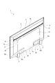
- FIG. 2 illustrates a display device according to an embodiment of the present technology together with Figs. 2 to 12, and is a perspective view showing a front side of the display device. It is a perspective view showing the back side of a display.
- FIG. 6 is a rear view of the display device shown with a rear cover removed. It is a conceptual diagram which shows the direction where the output audio
- FIG. 7 is a perspective view of the second speaker shown in a direction different from that of FIG. 6. It is a rear view which shows the arrangement position of a 2nd speaker. It is a perspective view which shows a part of display device. It is a rear view which shows another example of arrangement
- the embodiment shown below is one in which the display device of the present technology is applied to a television receiver that displays an image on the display.
- the scope of application of the present technology is not limited to television receivers, and can be widely applied to various display devices such as monitors used in personal computers and the like.
- front, back, up, down, left, and right directions are shown with the direction of the display surface of the display device (television receiver) facing the front side (front side).
- the display device (television receiver) 1 is, for example, formed in a substantially rectangular shape that is horizontally long and has a small thickness in the front-rear direction (see FIG. 1 ). It is used by being attached to the wall surface with a bracket or the like.
- the display device 1 includes a display 3 on which an image is displayed, a back chassis 4 arranged behind the display 3, an outer frame 5 called a bezel arranged on the outer peripheral side of the display 3 and the back chassis 4, a back chassis 4 and the like. And a rear cover 6 that covers from the rear (see FIGS. 1 to 3).
- the display 3 is formed in a plate shape that faces the front-back direction.
- a liquid crystal display is used as the display 3.
- the display 3 has a substrate and an optical sheet such as a polarizing film.
- the front surface of the display 3 is a display surface 3a on which an image is displayed.
- the back chassis 4 is made of, for example, a metal material, a resin material, or the like so that its outer shape is slightly larger than that of the display 3 (see FIG. 3).
- the back chassis 4 is provided with a portion other than the outer peripheral portion as a base surface portion 4a facing the front-rear direction, and the outer peripheral portion has an upper portion 4b and side portions 4c, 4c.
- the upper portion 4b is continuous with the upper end of the base surface portion 4a and is inclined so as to be displaced forward as it goes upward.
- the side portions 4c and 4c are respectively continuous with the left and right ends of the base surface portion 4a and are inclined so as to be displaced forward as they go outward in the lateral direction.
- An element mounting board (not shown) is attached to the front surface of the base surface portion 4a of the back chassis 4, and a plurality of light emitting elements such as light emitting diodes functioning as a backlight are mounted in a matrix on the element mounting board.
- a diffuser plate (not shown) that diffuses the light emitted from the light emitting element is disposed between the element mounting substrate and the display 3.
- control boards 7, 7,... are attached to the rear surface of the base surface portion 4a of the back chassis 4.
- the control board 7 for example, a power supply board that controls the power supply of the entire display device 1, a backlight board that controls the turning on and off of the light emitting elements, a signal processing board that controls the image and sound, and a display of the display 3.
- a control board or the like for performing control is provided.
- First speakers 8, 8 are attached to the rear surface of the base surface portion 4a of the back chassis 4 so as to be separated from each other in the left and right directions.
- the number of the first speakers 8 is arbitrary, and may be one or three or more.
- the first speaker 8 is, for example, a dynamic speaker, and is attached to the lower end of the base surface 4a.
- the first speaker 8 is, for example, a speaker whose output band is changed from the middle frequency range to the low frequency range, and the sound is output from the first speaker 8 downward, for example.
- the first speakers 8 are arranged symmetrically with respect to the center of the display device 1 in the left-right direction.
- the sound output from the first speakers 8 and 8 mainly goes around below the display 3 toward the front side (see FIG. 4 ).
- Second speakers 9 are attached to the rear surface of the base surface portion 4a of the back chassis 4 so as to be separated from each other in the left and right directions (see FIGS. 3 and 5).
- the number of the second speakers 9 is arbitrary, and may be one or three or more.
- two first speakers 8 and two second speakers 9 are provided, and the right channel sound is output from one of the first speaker 8 and the second speaker 9 and the other is output from the other.
- the left channel sound is output from the first speaker 8 and the second speaker 9, and the stereo mode sound is output by the right sound and the left sound.
- the monaural mode sound may be output from the first speaker 8 and the second speaker 9.
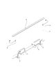
- the second speaker 9 includes a case body 10 made of a resin material, a piezoelectric element 11 that is operated by applying a voltage, and a diaphragm 12 that vibrates according to the operation of the piezoelectric element 11 (piezo speaker). ) (See FIGS. 5 to 7).
- the case body 10 is formed in a flat shape having a thin front and rear thickness, and a rear surface portion 13, a side surface portion 14, an upper surface portion 15, a lower surface portion 16, a connecting portion 17, and a reinforcing portion 18 are integrally formed.
- the rear surface portion 13 faces the front-rear direction and is formed in a flat plate shape larger than the side surface portion 14, the upper surface portion 15 and the lower surface portion 16.
- the side surface portion 14 is continuous with one side edge of the rear surface portion 13 and is formed in a vertically long substantially rectangular shape.
- the upper surface portion 15 and the lower surface portion 16 are formed in a horizontally long substantially rectangular shape continuous with the upper edge and the lower edge of the rear surface portion 13, respectively, and one side edge of the upper surface portion 15 and one side edge of the lower surface portion 16 are respectively formed.
- the upper and lower edges of the side surface portion 14 are continuous.
- the connecting portion 17 connects the other end portion of the upper surface portion 15 in the left-right direction and the other end portion of the lower surface portion 16 in the left-right direction, and is located on the front side of the rear surface portion 13. Therefore, an opening surrounded by the rear surface portion 13, the upper surface portion 15, the lower surface portion 16 and the connecting portion 17 is formed in the case body 10, and this opening serves as the sound passage hole 10a.
- the sound passage hole 10a is located on the opposite side of the side surface portion 14 in the left-right direction.
- the reinforcing portion 18 connects the rear surface portion 13 and the connecting portion 17, and is provided in the central portion in the vertical direction of the sound passage hole 10a.
- the reinforcing portion 18 prevents the rear surface portion 13 and the connecting portion 17 from being deformed in a direction in which they are in contact with each other.
- a frame-shaped cushion 19 is attached to the front of the case body 10.
- the internal space of the case body 10 is formed as an arrangement space 10b, and the sound passage hole 10a communicates with the arrangement space 10b.
- the case body 10 is gently inclined such that the upper surface portion 15 and the lower surface portion 16 are separated from each other in the left-right direction as they are separated from the side surface portion 14. Therefore, the distance between the upper surface portion 15 and the lower surface portion 16 is the smallest at the end portion on the side surface portion 14 side and the largest at the end portion on the sound passage hole 10a side.
- the piezoelectric element 11 is formed, for example, in a plate shape whose thickness direction is the front-back direction.
- Wiring board 20 is connected to piezoelectric element 11, and cable 21 is connected to wiring board 20. Therefore, a voltage is applied to the piezoelectric element 11 via the cable 21 and the wiring board 20.
- the wiring board 20 is, for example, a flexible printed wiring board, and is positioned and fixed inside and outside the case body 10 while being inserted between the cushion 19 and the case body 10.
- the diaphragm 12 is, for example, a metal plate whose thickness direction is in the front-back direction, and is joined to the inner surface of the rear surface portion 13.
- the vibrating plate 12 is slightly larger than the piezoelectric element 11, and the piezoelectric element 11 is attached to the front surface of the vibrating plate 12.
- the diaphragm 12 is deformed and vibrates according to the deformation of the piezoelectric element 11.
- the vibration of the diaphragm 12 is also transmitted to the case body 10, and the case body 10 also vibrates according to the vibration of the diaphragm 12.
- the case body 10 of the second speaker 9 is attached to the base surface portion 4a of the back chassis 4 via the cushion 19, and the case body 10 is attached to the base surface portion 4a of the back chassis 4 via the cushion 19. It is in a state capable of vibrating against.
- the second speakers 9 and 9 are attached to the left and right ends of the back chassis 4, for example, to the left and right ends of the base surface 4a with the sound passage holes 10a and 10a positioned outside the side face 14 in the left and right direction. In the vertical direction, it is attached to the upper half of the back chassis 4 and is located above the first speakers 8, 8. Specifically, when the entire height of the display device 1 is L and the lower end is 0, the second speakers 9 and 9 are located between 0.7L and 0.85L (FIG. 8). reference).
- the second speaker 9 is, for example, a speaker whose output band is changed from a high frequency range to a middle frequency range or a high frequency range, and sound is emitted to the side from the sound passage hole 10a.
- the sound output from the second speakers 9 and 9 mainly goes around the side of the display 3 toward the front side (see FIG. 4 ). Further, the second speaker 9 vibrates not only the diaphragm 12 but also the case body 10, so that sound is output to the surroundings of the case body 10.
- the outer frame 5 is composed of, for example, four parts located vertically and horizontally, and is attached to the outer peripheral portion of the back chassis 4 from the outer peripheral side (see FIGS. 2 and 9).
- the rear cover 6 is slightly smaller than the back chassis 4, and the part excluding the lower end is provided as the main body 22 (see FIG. 2).
- the rear cover 6 has a protrusion 23 projecting downward from the center of the main body 22 in the left-right direction, and the left and right of the protrusion 23 are formed as placement notches 6a, 6a.
- a band portion 24 that extends in the left-right direction is provided in a portion near the upper end of the main body portion 22, and the band portion 24 is formed in a shape that is opened both in the front and in the left and right (see FIG. 9 ).
- the left and right openings of the band portion 24 are formed as emission holes 24a, 24a.
- the main body 22 is provided with a decorative portion 25 continuously from the upper end of the band portion 24, and the decorative portion 25 is composed of a plurality of concave and convex portions arranged alternately on the left and right.
- Small holes 22a, 22a,... Penetrating vertically are formed at the left and right ends of the main body 22 in a continuous portion of the belt 24 and the decorative portion 25.
- the small holes 22a, 22a,... are formed by processing the main body portion 22 so that there is a gap between the concave portion of the decorative portion 25 and the belt portion 24, and are communicated with the space inside the belt portion 24. ..
- left and right ends of the main body 22 are inclined so as to be displaced forward as they go outward in the same way as the sides 4c and 4c of the back chassis 4.
- the rear cover 6 is attached to the back chassis 4 so as to cover the base surface portion 4a from behind (see FIG. 2).
- the control boards 7, 7,... are covered from behind by the main body portion 22 or the protruding portions 23, and the placement notches 6a and 6a respectively have the first speaker. 8 and 8 are positioned, and the left and right ends of the band portion 24 cover the second speakers 9 and 9 from the rear, respectively.
- the cover 26 has a rear closing portion 26a facing the front-rear direction and a lower closing portion 26b protruding forward from a lower end portion of the rear closing portion 26a, and a mesh-shaped discharging portion is formed in the lower closing portion 26b. Has been done.
- the sound in the mid-range to the low-range output from the first speaker 8 is emitted downward from the emission part of the lower blocking portion 26b, and goes around the lower side of the display 3 toward the front side.
- the high-range to middle-range or high-range sound output from the second speaker 9 is mainly emitted to the side from the sound passage hole 10a of the case body 10 through the emission hole 24a of the band portion 24. Go around the sides of the display 3 and head to the front side. A part of the sound output from the second speaker 9 is emitted upward from the case body 10 through the small holes 22a, 22a,... Go around and head to the front side.
- the first speaker 8 disposed between the display 3 and the rear cover 6 and the first speaker 8 disposed between the display 3 and the rear cover 6 are disposed above the first speaker 8.
- the second speaker 9 is positioned, and the second speaker 9 outputs sound by the operation of the piezoelectric element 11 and has a higher sound output band than the first speaker 8.
- the sound in the higher frequency band of the sound output from the first speaker 8 is output from the second speaker 9 while going around the display 3 from above the first speaker 8 toward the front side.
- the sound in the lower frequency range than the sound band goes around the display 3 from the lower side of the second speaker 9 toward the front side.
- the sound output from the first speaker 8 that wraps around the display 3 and the sound that outputs from the second speaker 9 that wraps around the display 3 are in the central portion of the display 3 that is being visually recognized by the user. It becomes easier to recognize the image as if it is being output from, and it is possible to secure a realistic viewing state due to the sense of unity between the image and the image and the sound.
- the second speaker 9 is located between 0.7L and 0.85L.
- the second speaker 9 that outputs the sound in the high frequency range from the first speaker 8 is located in the predetermined range on the upper end side, the sound that is output from the second speaker 9 from the left and right sides of the display 3. Since it becomes easier to wrap around and head toward the front side, a high localization effect of a sound image can be secured.
- two second speakers 9 and 9 are provided, and the two second speakers 9 and 9 are located apart from each other on the left and right.
- the audio path so that the sounds output from the two second speakers 9 and 9 are circulated from the left side and the right side of the display 3 and directed toward the front side. It is possible to obtain a feeling of expansiveness and a good sound image localization, and it is possible to secure a realistic viewing state for the user.
- the two second speakers 9 and 9 are attached to positions on the left and right ends of the back chassis 4 so that the sounds output from the second speakers 9 and 9 are output from the left and right sides of the display 3, respectively. It becomes easier to wrap around, and it is possible to obtain a further sense of sound image expanse and better sound image localization.
- the second speaker 9 has a case body 10, a piezoelectric element 11, and a vibration plate 12, and a voice passage hole 10a is formed in the case body 10 so that an output voice can pass therethrough and communicate with the arrangement space 10b. There is.
- the sound output by vibrating the diaphragm 12 by the application of the voltage to the piezoelectric element 11 goes to the outside through the sound passage hole 10a, and is desired depending on the position where the sound passage hole 10a is formed on the case body 10.
- the sound can be guided in the direction of, and the sound image localization can be enhanced, and a good viewing state can be secured.
- the case body 10 is formed in a shape that becomes wider as it approaches the sound passage hole 10a, the outputted sound passes along the upper surface portion 15 and the lower surface portion 16 which are the surface portions on both sides in the width direction. As the sound passage hole 10a progresses toward the hole 10a, the size in the width direction of the sound passage hole 10a increases, and a sound with high sound pressure can be smoothly emitted from the sound passage hole 10a.
- the second speakers 9 and 9 may be arranged, for example, at both left and right ends of the back chassis 4 (see FIG. 10). By arranging the second speakers 9 and 9 at both left and right ends of the back chassis 4, it becomes easier for the sounds output from the second speakers 9 and 9 to wrap around from the left and right sides of the display 3, respectively, and the sound image It is possible to obtain a feeling of expanse and good sound image localization.
- the second speaker 9 provided with the case body 10 having the internal space 10b has been shown as an example.
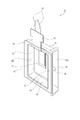
- a second case 9 having a different case body configuration is provided. It is also possible to use the speaker 9A (see FIGS. 11 and 12).
- the second speaker 9A has a case body 10A made of a resin material, a piezoelectric element 11 that is operated by applying a voltage, and a diaphragm 12 that vibrates according to the operation of the piezoelectric element 11.
- the case body 10A has a mounting portion 30 to which the diaphragm 12 is mounted and leg portions 31 and 31 protruding from the mounting portion 30.
- the mounting portion 30 is formed in a substantially rectangular plate shape, and has a shallow recess 30a that is open on one side in the thickness direction.
- the leg portions 31, 31 are projected from the other surface of the mounting portion 30 in the thickness direction, and are vertically separated from each other.
- the mounting portion 30 is inclined with respect to the protruding direction of the leg portion 31. Cushions 19 and 19 are attached to the tip surfaces of the leg portions 31 and 31, respectively.
- the diaphragm 12 is joined to the mounting portion 30 while being arranged in the recess 30a.
- the back chassis 4A is used, and the back chassis 4A is formed in a substantially flat plate shape as a whole.
- the rear cover 6A is formed to have substantially the same size as the back chassis 4A, and the left and right end portions approach both ends in the left-right direction as they approach each other. It is inclined so as to approach the back chassis 4A.
- the leg portions 31 and 31 of the case body 10A are attached to the left and right ends of the back chassis 4A via the cushions 19 and 19, and the case body 10A is attached to the back chassis 4A via the cushions 19 and 19. Since it is attached to the back chassis 4A with the double-sided tape, the case body 10A can vibrate with respect to the back chassis 4A. Alternatively, it may be attached by screwing.
- the mounting portion 30 of the case body 10A of the second speaker 9A is slanted, and the mounting portion 30 is positioned along the slanted state of the rear cover 6A when mounted on the back chassis 4A. Therefore, the piezoelectric element 11 and the vibrating plate 12 mounted on the mounting portion 30 are positioned so as to face each other in a state substantially parallel to the inner surface of the rear cover 6A.
- the sound output from the second speaker 9A is emitted to the side via the emission hole 24a, goes around the side of the display 3 and goes to the front side.
- an emission hole penetrating in the front and rear may be formed at a position in the rear cover 6A that faces the piezoelectric element 11 and the vibration plate 12. , The sound output from the second speaker 9A is emitted rearward through the emission hole and wraps around the side or upper side of the display 3 toward the front side.
- .. may be formed in the rear cover 6A.
- the small holes 22a, 22a,... are formed, the sound output from the second speaker 9A is formed. Are emitted upward through the small holes 22a, 22a,... And wrap around above the display 3 toward the front side.
- the case body 10A is formed into a substantially plate shape, and the leg portions 31 and 31 in the protruding direction from the mounting portion 30 are arranged depending on the space in which they are arranged.
- the length By changing the length, it becomes possible to arrange the second speaker 9A in a small space. Therefore, it is possible to reduce the size of the second speaker 9A and improve the degree of freedom in design by effectively utilizing the space.
- the second speakers 9A and 9A since it becomes possible to arrange the second speakers 9A and 9A at both left and right ends, it becomes easy for the sounds output from the second speakers 9A and 9A to wrap around from the left and right sides of the display 3, respectively. It is possible to obtain a sense of sound image expanse and good sound image localization.
- the present technology may also be configured as below.
- a display where an image is displayed on the display surface, A rear cover arranged on the back side of the display, A first speaker disposed between the display and the rear cover, A second speaker disposed between the display and the rear cover and positioned above the first speaker, A display device in which the second speaker outputs sound according to the operation of the piezoelectric element, and the output band of the sound is higher than that of the first speaker.
- Two second speakers are provided, The display device according to (1) or (2), in which the two second speakers are positioned apart from each other in the left and right directions.
- a case body whose internal space is formed as an arrangement space, A piezoelectric element arranged in the arrangement space and operated by applying a voltage, A vibration plate that vibrates according to the operation of the piezoelectric element and is attached to the inner surface of the case body; A speaker having a voice passage hole formed in the case body, through which the outputted voice is passed and communicated with the arrangement space.
- 1-display device 3-display, 3a-display surface, 6-rear cover, 8-first speaker, 9-second speaker, 10-case body, 10a-voice passage hole, 10b-arrangement space, 11- Piezoelectric element, 12, vibration plate, 9A, second speaker, 10A, case body
Abstract
音像定位効果を高めて画像や映像と音声との一体感が生じる良好な視聴状態を確保する。 表示面に画像が表示されるディスプレイと、ディスプレイの背面側に配置されたリアカバーと、ディスプレイとリアカバーの間に配置された第1のスピーカーと、ディスプレイとリアカバーの間に配置され第1のスピーカーより上方に位置された第2のスピーカーとを備え、第2のスピーカーは圧電素子の動作に応じて音声を出力し第1のスピーカーより音声の出力帯域が高くされた。これにより、恰も視認中のディスプレイから音声が出力されているように認識されるため、音像定位効果を高めて画像や映像と音声との一体感が生じる良好な視聴状態を確保することができる。
Description
本技術は、表示面に画像が表示されるディスプレイを有しスピーカーから音声の出力が行われる表示装置についての技術分野に関する。
テレビジョン受像器やパーソナルコンピューター等の表示装置には、画像が表示される表示面を有するディスプレイが設けられ、ディスプレイの背面側にスピーカー等が配置され、スピーカー等がリアカバーによって背面側から覆われたものがある(例えば、特許文献1参照)。
特許文献1に記載された表示装置にあっては、ディスプレイの下端部における背面側にスピーカーが配置され、スピーカーがリアカバーによって背面側から覆われ、スピーカーから出力される音声がディスプレイの下側を通って前方へ向かう構成にされている。
ところで、表示装置の視聴時に、使用者はディスプレイに表示される画像や映像を視認した状態で音声を聴き取るため、音声が恰も視認中のディスプレイから出力されているように認識されることが画像や映像と音声との一体感が生じ、望ましい視聴状態とされる。
従って、ディスプレイの周囲から音声が聞こえるような認識での視聴状態は、画像や映像と音声との一体感に乏しく、使用者が画像や映像との関係において音の聞こえ方に違和感を生じ良好な音像定位を得られない可能性がある。
そこで、本発明表示装置は、音像定位効果を高めて画像や映像と音声との一体感が生じる良好な視聴状態を確保することを目的とする。
第1に、本技術に係る表示装置は、表示面に画像が表示されるディスプレイと、前記ディスプレイの背面側に配置されたリアカバーと、前記ディスプレイと前記リアカバーの間に配置された第1のスピーカーと、前記ディスプレイと前記リアカバーの間に配置され前記第1のスピーカーより上方に位置された第2のスピーカーとを備え、前記第2のスピーカーは圧電素子の動作に応じて音声を出力し前記第1のスピーカーより音声の出力帯域が高くされたものである。
これにより、第1のスピーカーから出力される音声の帯域より高域の音声が第1のスピーカーよりも上方側からディスプレイを回り込んで正面側へ向かうと共に第2のスピーカーから出力される音声の帯域より低域の音声が第2のスピーカーよりも下方側からディスプレイを回り込んで正面側へ向かうため、恰も視認中のディスプレイから音声が出力されているように認識される。
第2に、上記した表示装置においては、全体の高さをLとし下端を0としたときに、前記第2のスピーカーが0.7Lから0.85Lまでの間に位置されることが望ましい。
これにより、第2のスピーカーから出力される音声がディスプレイを左右方向から回り込んで正面側へ向かい易くなる。
第3に、上記した表示装置においては、前記第2のスピーカーが二つ設けられ、前記二つの第2のスピーカーが左右に離隔して位置されることが望ましい。
これにより、二つの第2のスピーカーから出力された音声をそれぞれディスプレイの左方と右方から回り込ませて正面側へ向かわせるように音声経路を設定することが可能になる。
第4に、本技術に係るスピーカーは、内部空間が配置空間として形成されたケース体と、前記配置空間に配置され電圧の印加により動作される圧電素子と、前記圧電素子の動作に応じて振動し前記ケース体の内面に取り付けられた振動板とを備え、前記ケース体には出力される音声が通過され前記配置空間に連通された音声通過孔が形成されたものである。
これにより、圧電素子に対する電圧の印加により振動板が振動することにより出力される音声が音声通過孔を通って外部へ向かうため、音声通過孔のケース体に対する形成位置に応じて所望の方向へ音声を導くことが可能になる。
第5に、上記した表示装置においては、前記ケース体が前記音声通過孔に近付くに従って幅が広くなる形状に形成されることが望ましい。
これにより、出力された音声が幅方向における両側の部分に沿って音声通過孔へ向けて進行すると共に音声通過孔の幅方向における大きさが大きくなる。
以下に、本技術表示装置を実施するための形態を添付図面に従って説明する。
以下に示した実施の形態は、本技術表示装置を、ディスプレイに画像を表示するテレビジョン受像器に適用したものである。
尚、本技術の適用範囲はテレビジョン受像器に限られることはなく、パーソナルコンピューター等に用いられるモニター等の各種の表示装置に広く適用することができる。
以下の説明にあっては、表示装置(テレビジョン受像器)の表示面が向く方向を前方側(正面側)として前後上下左右の方向を示す。
<表示装置の構成>
表示装置(テレビジョン受像器)1は、例えば、横長で前後方向の厚みが薄い略矩形状に形成され(図1参照)、例えば、スタンド2によって床面等の設置面に設置されたり図示しないブラケット等によって壁面に取り付けられて用いられる。
表示装置(テレビジョン受像器)1は、例えば、横長で前後方向の厚みが薄い略矩形状に形成され(図1参照)、例えば、スタンド2によって床面等の設置面に設置されたり図示しないブラケット等によって壁面に取り付けられて用いられる。
表示装置1は画像が表示されるディスプレイ3とディスプレイ3の後方に配置されたバックシャーシ4とディスプレイ3及びバックシャーシ4の外周側に配置されたベゼルと称される外枠5とバックシャーシ4等を後方から覆うリアカバー6とを有している(図1乃至図3参照)。
ディスプレイ3は前後方向を向く板状に形成され、ディスプレイ3としては、例えば、液晶ディスプレイが用いられている。ディスプレイ3は基板や偏光フィルム等の光学シートを有している。ディスプレイ3の前面は画像が表示される表示面3aとされている。
バックシャーシ4は、例えば、金属材料や樹脂材料等によって外形状がディスプレイ3より一回り大きい形状に形成されている(図3参照)。バックシャーシ4は外周部を除く部分が前後方向を向くベース面部4aとして設けられ、外周部が上部4bと側部4c、4cとを有している。上部4bはベース面部4aの上端に連続され上方へ行くに従って前方に変位するように傾斜されている。側部4c、4cはそれぞれベース面部4aの左右両端に連続され側方における外方へ行くに従って前方に変位するように傾斜されている。
バックシャーシ4におけるベース面部4aの前面には図示しない素子搭載基板が取り付けられ、素子搭載基板にはバックライトとして機能する発光ダイオード等の複数の発光素子がマトリクス状に搭載されている。素子搭載基板とディスプレイ3の間には発光素子から出射された光を拡散する図示しない拡散板が配置されている。
バックシャーシ4におけるベース面部4aの後面には各種の制御基板7、7、・・・が取り付けられている。制御基板7としては、例えば、表示装置1の全体の電源制御を行う電源基板、発光素子の点消灯制御を行うバックライト用基板、画像や音声等の制御を行う信号処理基板、ディスプレイ3の表示制御を行う制御基板等が設けられている。
バックシャーシ4におけるベース面部4aの後面には第1のスピーカー8、8が左右に離隔して取り付けられている。尚、第1のスピーカー8の数は任意であり、一つでもよく、三つ以上であってもよい。第1のスピーカー8は、例えば、ダイナミック型のスピーカーであり、ベース面部4aの下端部に取り付けられている。第1のスピーカー8としては、例えば、出力帯域が中音域から低音域にされたスピーカーであり、第1のスピーカー8からは音声が、例えば、下方へ向けて出力される。
第1のスピーカー8、8は表示装置1の左右方向における中央を基準として左右対称な位置に配置されている。第1のスピーカー8、8から出力された音声は、主として、ディスプレイ3の下方を回り込んで正面側へ向かう(図4参照)。
バックシャーシ4におけるベース面部4aの後面には第2のスピーカー9、9が左右に離隔して取り付けられている(図3及び図5参照)。尚、第2のスピーカー9の数は任意であり、一つでもよく、三つ以上であってもよい。
上記したように、第1のスピーカー8と第2のスピーカー9はそれぞれ二つずつ設けられており、一方の第1のスピーカー8と第2のスピーカー9から右チャンネルの音声が出力され、他方の第1のスピーカー8と第2のスピーカー9から左チャンネルの音声が出力され、右側の音声と左側の音声とによってステレオモードの音声出力が行われる。
但し、表示装置1においては、第1のスピーカー8と第2のスピーカー9からモノラルモードの音声出力が行われてもよい。
第2のスピーカー9は樹脂材料によって形成されたケース体10と電圧が印加されて動作される圧電素子11と圧電素子11の動作に応じて振動する振動板12とを有する圧電素子スピーカー(ピエゾスピーカー)である(図5乃至図7参照)。
ケース体10は前後の厚みの薄い扁平な形状に形成され、後面部13と側面部14と上面部15と下面部16と連結部17と補強部18が一体に形成されて成る。
後面部13は前後方向を向き側面部14と上面部15と下面部16より大きい平板状に形成されている。側面部14は後面部13における一方の側縁に連続され縦長の略矩形状に形成されている。上面部15と下面部16はそれぞれ後面部13における上縁と下縁に連続され横長の略矩形状に形成され、上面部15の一方の側縁と下面部16の一方の側縁とはそれぞれ側面部14の上下両縁に連続されている。
連結部17は上面部15の左右方向における他端部と下面部16の左右方向における他端部とを連結し、後面部13の前側に位置されている。従って、ケース体10には後面部13と上面部15と下面部16と連結部17によって囲まれた開口が形成され、この開口が音声通過孔10aとされている。音声通過孔10aは左右方向において側面部14の反対側に位置されている。
補強部18は後面部13と連結部17を連結し、音声通過孔10aの上下方向における中央部に設けられている。補強部18によって後面部13と連結部17の互いに離接する方向への変形が防止されている。
ケース体10の前面には枠状のクッション19が貼り付けられている。ケース体10の内部空間は配置空間10bとして形成され、音声通過孔10aが配置空間10bに連通されている。
ケース体10は上面部15と下面部16が左右方向において側面部14から離隔するに従って互いに離隔する状態で緩やかに傾斜されている。従って、上面部15と下面部16の距離は側面部14側の端部が最も小さく音声通過孔10a側の端部が最も大きくされている。
圧電素子11は、例えば、厚み方向が前後方向にされた板状に形成されている。圧電素子11には配線板20が接続され、配線板20にはケーブル21が接続されている。従って、圧電素子11にはケーブル21と配線板20を介して電圧が印加される。配線板20は、例えば、フレキシブルプリント配線板であり、クッション19とケース体10の間に挿入された状態でケース体10の内外に亘って位置されて固定されている。
振動板12は、例えば、厚み方向が前後方向にされた金属板であり、後面部13の内面に接合されている。振動板12は圧電素子11より一回り大きくされ、振動板12の前面には圧電素子11が貼り付けられている。
従って、圧電素子11にケーブル21と配線板20を介して電圧が印加され圧電素子11が変形されると、圧電素子11の変形に応じて振動板12が変形されて振動する。振動板12の振動はケース体10にも伝達され、ケース体10も振動板12の振動に応じて振動する。
第2のスピーカー9はケース体10がクッション19を介してバックシャーシ4のベース面部4aに取り付けられ、ケース体10がクッション19を介してベース面部4aに取り付けられるため、ケース体10がバックシャーシ4に対して振動可能な状態にされている。
第2のスピーカー9、9は音声通過孔10a、10aが左右方向において側面部14より外側に位置された状態でバックシャーシ4の左右両端寄りの位置、例えば、ベース面部4aの左右両端部に取り付けられ、上下方向においてはバックシャーシ4の上半部に取り付けられ、第1のスピーカー8、8より上側に位置されている。具体的には、表示装置1の全体の高さをLとし下端を0としたときに、第2のスピーカー9、9は0.7Lから0.85Lまでの間に位置されている(図8参照)。
第2のスピーカー9は、例えば、出力帯域が高音域から中音域又は高音域にされたスピーカーであり、音声が音声通過孔10aから側方に放出される。第2のスピーカー9、9から出力された音声は、主として、ディスプレイ3の側方を回り込んで正面側へ向かう(図4参照)。また、第2のスピーカー9は振動板12に加えてケース体10も振動するため、ケース体10の周囲にも音声が出力される。
外枠5は、例えば、上下左右に位置する四つの部分が結合されて構成され、バックシャーシ4の外周部に外周側から取り付けられている(図2及び図9参照)。
リアカバー6はバックシャーシ4より一回り小さくされ、下端部を除く部分が本体部22として設けられている(図2参照)。リアカバー6は本体部22の左右方向における中央部から下方に突出された突状部23を有し、突状部23の左右が配置用切欠6a、6aとして形成されている。
本体部22の上端寄りの部分には左右に延びる帯部24が設けられ、帯部24は前方と左右両方に開口された形状に形成されている(図9参照)。帯部24の左右の開口は放出孔24a、24aとして形成されている。本体部22には帯部24の上端部に連続して装飾部25が設けられ、装飾部25は左右に交互に並ぶ複数の凹凸部によって構成されている。
本体部22の左右両端部には帯部24と装飾部25の連続部分に、上下に貫通された小孔22a、22a、・・・が形成されている。小孔22a、22a、・・・は装飾部25の凹部と帯部24の間に隙間を有するように本体部22を加工することにより形成され、帯部24の内部の空間に連通されている。
尚、本体部22の左右両端部はバックシャーシ4の側部4c、4cと同様に、それぞれ側方における外方へ行くに従って前方に変位するように傾斜されている。
リアカバー6はベース面部4aを後方から覆う状態でバックシャーシ4に取り付けられる(図2参照)。リアカバー6がバックシャーシ4に取り付けられた状態においては、制御基板7、7、・・・が本体部22又は突状部23によって後方から覆われ、配置用切欠6a、6aにそれぞれ第1のスピーカー8、8が位置され、帯部24の左右両端部によってそれぞれ第2のスピーカー9、9が後方から覆われる。
リアカバー6がバックシャーシ4に取り付けられた状態においては、配置用切欠6a、6aをそれぞれ閉塞するカバー26、26がリアカバー6に後方から取り付けられ、カバー26、26によってそれぞれ第1のスピーカー8、8が覆われる。カバー26は前後方向を向く後側閉塞部26aと後側閉塞部26aの下端部から前方に突出された下側閉塞部26bとを有し、下側閉塞部26bにメッシュ状の放出部が形成されている。
従って、第1のスピーカー8から出力された中音域から低音域の音声は下側閉塞部26bの放出部から下方に放出され、ディスプレイ3の下方を回り込んで正面側へ向かう。
一方、第2のスピーカー9から出力された高音域から中音域又は高音域の音声は、主として、ケース体10の音声通過孔10aから帯部24の放出孔24aを介して側方に放出され、ディスプレイ3の側方を回り込んで正面側へ向かう。また、第2のスピーカー9から出力された音声の一部は、ケース体10から本体部22に形成された小孔22a、22a、・・・を介して上方に放出され、ディスプレイ3の上方を回り込んで正面側へ向かう。
<まとめ>
以上に記載した通り、表示装置1にあっては、ディスプレイ3とリアカバー6の間に配置された第1のスピーカー8と、ディスプレイ3とリアカバー6の間に配置され第1のスピーカー8より上方に位置された第2のスピーカー9とを備え、第2のスピーカー9は圧電素子11の動作により音声を出力し第1のスピーカー8より音声の出力帯域が高くされている。
以上に記載した通り、表示装置1にあっては、ディスプレイ3とリアカバー6の間に配置された第1のスピーカー8と、ディスプレイ3とリアカバー6の間に配置され第1のスピーカー8より上方に位置された第2のスピーカー9とを備え、第2のスピーカー9は圧電素子11の動作により音声を出力し第1のスピーカー8より音声の出力帯域が高くされている。
従って、第1のスピーカー8から出力される音声の帯域より高域の音声が第1のスピーカー8よりも上方側からディスプレイ3を回り込んで正面側へ向かうと共に第2のスピーカー9から出力される音声の帯域より低域の音声が第2のスピーカー9よりも下方側からディスプレイ3を回り込んで正面側へ向かう。
これにより、恰も視認中のディスプレイから音声が出力されているように認識され、音像定位効果を高めて画像や映像と音声との一体感が生じる良好な視聴状態を確保することができる。
特に、ディスプレイ3を回り込んだ第1のスピーカー8から出力された音声とディスプレイ3を回り込んだ第2のスピーカー9から出力された音声とが、使用者において恰も視認中のディスプレイ3の中央部から出力されているように認識され易くなり、画像や映像と音声との一体感により臨場感のある視聴状態を確保することができる。
また、表示装置1の全体の高さをLとし下端を0としたときに、第2のスピーカー9が0.7Lから0.85Lまでの間に位置されている。
従って、第1のスピーカー8より高音域の音声を出力する第2のスピーカー9が上端側において所定の範囲に位置されるため、第2のスピーカー9から出力される音声がディスプレイ3を左右方向から回り込んで正面側へ向かい易くなるため、音像の高い定位効果を確保することができる。
さらに、二つの第2のスピーカー9、9が設けられ、二つの第2のスピーカー9、9が左右に離隔して位置されている。
従って、二つの第2のスピーカー9、9から出力された音声をそれぞれディスプレイ3の左方と右方から回り込ませて正面側へ向かわせるように音声経路を設定することが可能になるため、音像の広がり感及び良好な音像定位が得られ、使用者において臨場感のある視聴状態を確保することができる。
特に、二つの第2のスピーカー9、9がバックシャーシ4の左右両端寄りの位置に取り付けられることにより、第2のスピーカー9、9から出力された音声がそれぞれディスプレイ3の左方と右方から回り込み易くなり、一層の音像の広がり感及びより良好な音像定位を得ることができる。
また、第2のスピーカー9はケース体10と圧電素子11と振動板12を有し、ケース体10には出力される音声が通過され配置空間10bに連通された音声通過孔10aが形成されている。
従って、圧電素子11に対する電圧の印加により振動板12が振動することにより出力される音声が音声通過孔10aを通って外部へ向かうため、音声通過孔10aのケース体10に対する形成位置に応じて所望の方向へ音声を導くことが可能になり、音像定位を高めて良好な視聴状態を確保することができる。
さらに、ケース体10が音声通過孔10aに近付くに従って幅が広くなる形状に形成されているため、出力された音声が幅方向における両側の面部である上面部15と下面部16に沿って音声通過孔10aへ向けて進行すると共に音声通過孔10aの幅方向における大きさが大きくなり、音声通過孔10aから高い音圧の音声を円滑に放出することができる。
<その他>
上記には、第2のスピーカー9、9がバックシャーシ4の左右両端寄りの位置に配置された例を示したが、第2のスピーカー9、9は第1のスピーカー8より上方に位置されていれば何れの位置に配置することも可能である。
上記には、第2のスピーカー9、9がバックシャーシ4の左右両端寄りの位置に配置された例を示したが、第2のスピーカー9、9は第1のスピーカー8より上方に位置されていれば何れの位置に配置することも可能である。
第2のスピーカー9、9は、例えば、バックシャーシ4の左右両端部に配置されていてもよい(図10参照)。第2のスピーカー9、9がバックシャーシ4の左右両端部に配置されることにより、第2のスピーカー9、9から出力された音声がそれぞれディスプレイ3の左方と右方から回り込み易くなり、音像の広がり感及び良好な音像定位を得ることができる。
また、上記には、内部空間10bを有するケース体10を備えた第2のスピーカー9を例として示したが、第2のスピーカー9に代えて以下のようなケース体の構成が異なる第2のスピーカー9Aを用いることも可能である(図11及び図12参照)。
第2のスピーカー9Aは樹脂材料によって形成されたケース体10Aと電圧が印加されて動作される圧電素子11と圧電素子11の動作に応じて振動する振動板12とを有する。
ケース体10Aは振動板12が取り付けられる取付部30と取付部30から突出された脚部31、31とを有している。取付部30は略矩形の板状に形成され、厚み方向における一方に開口された浅い凹部30aを有している。脚部31、31は取付部30の厚み方向における他方の面から突出され、上下に離隔して設けられている。取付部30は脚部31の突出方向に対して傾斜されている。脚部31、31の先端面にはそれぞれクッション19、19が貼り付けられている。
取付部30には振動板12が凹部30aに配置された状態で接合されている。
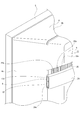
第2のスピーカー9Aが用いられる例においては、例えば、バックシャーシ4Aが用いられており、バックシャーシ4Aは全体が略平板状に形成されている。また、第2のスピーカー9Aが用いられる例においては、例えば、リアカバー6Aが用いられており、リアカバー6Aはバックシャーシ4Aと略同じ大きさに形成され、左右両端部が左右方向における両端に近付くに従ってバックシャーシ4Aに近付くように傾斜されている。
第2のスピーカー9Aはケース体10Aの脚部31、31がクッション19、19を介してバックシャーシ4Aの左右方向における端部に取り付けられ、ケース体10Aがクッション19、19を介してバックシャーシ4Aに両面テープで取り付けられるため、ケース体10Aがバックシャーシ4Aに対して振動可能な状態にされている。または、ネジ止めで取り付けられても良い。
第2のスピーカー9Aはケース体10Aの取付部30が傾斜されており、バックシャーシ4Aに取り付けられた状態において取付部30がリアカバー6Aの傾斜状態に沿って位置される。従って、取付部30に取り付けられた圧電素子11と振動板12はリアカバー6Aの内面に略平行な状態で対向して位置される。
第2のスピーカー9Aから出力された音声は、放出孔24aを介して側方に放出され、ディスプレイ3の側方を回り込んで正面側へ向かう。
尚、第2のスピーカー9Aが用いられた例においては、リアカバー6Aにおける圧電素子11と振動板12に対向する位置に前後に貫通された放出孔が形成されていてもよく、このような放出孔が形成されている場合には、第2のスピーカー9Aから出力された音声が放出孔を介して後方に放出され、ディスプレイ3の側方や上方を回り込んで正面側へ向かう。
また、リアカバー6Aに小孔22a、22a、・・・が形成されていてもよく、小孔22a、22a、・・・が形成されている場合には、第2のスピーカー9Aから出力された音声が小孔22a、22a、・・・を介して上方に放出され、ディスプレイ3の上方を回り込んで正面側へ向かう。
上記のように第2のスピーカー9Aが用いられる場合には、ケース体10Aが略板状に形成されており、配置されるスペースに応じて脚部31、31の取付部30からの突出方向における長さを変えることにより、小さなスペースに第2のスピーカー9Aを配置することが可能になる。従って、第2のスピーカー9Aの小型化を図ることができると共にスペースの有効活用による設計の自由度の向上を図ることができる。
また、第2のスピーカー9A、9Aを左右両端部に配置することが可能になるため、第2のスピーカー9A、9Aから出力された音声がそれぞれディスプレイ3の左方と右方から回り込み易くなり、音像の広がり感及び良好な音像定位を得ることができる。
<本技術>
本技術は、以下のような構成にすることもできる。
本技術は、以下のような構成にすることもできる。
(1)
表示面に画像が表示されるディスプレイと、
前記ディスプレイの背面側に配置されたリアカバーと、
前記ディスプレイと前記リアカバーの間に配置された第1のスピーカーと、
前記ディスプレイと前記リアカバーの間に配置され前記第1のスピーカーより上方に位置された第2のスピーカーとを備え、
前記第2のスピーカーは圧電素子の動作に応じて音声を出力し前記第1のスピーカーより音声の出力帯域が高くされた
表示装置。
表示面に画像が表示されるディスプレイと、
前記ディスプレイの背面側に配置されたリアカバーと、
前記ディスプレイと前記リアカバーの間に配置された第1のスピーカーと、
前記ディスプレイと前記リアカバーの間に配置され前記第1のスピーカーより上方に位置された第2のスピーカーとを備え、
前記第2のスピーカーは圧電素子の動作に応じて音声を出力し前記第1のスピーカーより音声の出力帯域が高くされた
表示装置。
(2)
全体の高さをLとし下端を0としたときに、
前記第2のスピーカーが0.7Lから0.85Lまでの間に位置された
前記(1)に記載の表示装置。
全体の高さをLとし下端を0としたときに、
前記第2のスピーカーが0.7Lから0.85Lまでの間に位置された
前記(1)に記載の表示装置。
(3)
前記第2のスピーカーが二つ設けられ、
前記二つの第2のスピーカーが左右に離隔して位置された
前記(1)又は前記(2)に記載の表示装置。
前記第2のスピーカーが二つ設けられ、
前記二つの第2のスピーカーが左右に離隔して位置された
前記(1)又は前記(2)に記載の表示装置。
(4)
内部空間が配置空間として形成されたケース体と、
前記配置空間に配置され電圧の印加により動作される圧電素子と、
前記圧電素子の動作に応じて振動し前記ケース体の内面に取り付けられた振動板とを備え、
前記ケース体には出力される音声が通過され前記配置空間に連通された音声通過孔が形成された
スピーカー。
内部空間が配置空間として形成されたケース体と、
前記配置空間に配置され電圧の印加により動作される圧電素子と、
前記圧電素子の動作に応じて振動し前記ケース体の内面に取り付けられた振動板とを備え、
前記ケース体には出力される音声が通過され前記配置空間に連通された音声通過孔が形成された
スピーカー。
(5)
前記ケース体が前記音声通過孔に近付くに従って幅が広くなる形状に形成された
前記(4)に記載のスピーカー。
前記ケース体が前記音声通過孔に近付くに従って幅が広くなる形状に形成された
前記(4)に記載のスピーカー。
1・表示装置、3・ディスプレイ、3a・表示面、6・リアカバー、8・第1のスピーカー、9・第2のスピーカー、10・ケース体、10a・音声通過孔、10b・配置空間、11・圧電素子、12・振動板、9A・第2のスピーカー、10A・ケース体
Claims (5)
- 表示面に画像が表示されるディスプレイと、
前記ディスプレイの背面側に配置されたリアカバーと、
前記ディスプレイと前記リアカバーの間に配置された第1のスピーカーと、
前記ディスプレイと前記リアカバーの間に配置され前記第1のスピーカーより上方に位置された第2のスピーカーとを備え、
前記第2のスピーカーは圧電素子の動作に応じて音声を出力し前記第1のスピーカーより音声の出力帯域が高くされた
表示装置。 - 全体の高さをLとし下端を0としたときに、
前記第2のスピーカーが0.7Lから0.85Lまでの間に位置された
請求項1に記載の表示装置。 - 前記第2のスピーカーが二つ設けられ、
前記二つの第2のスピーカーが左右に離隔して位置された
請求項1に記載の表示装置。 - 内部空間が配置空間として形成されたケース体と、
前記配置空間に配置され電圧の印加により動作される圧電素子と、
前記圧電素子の動作に応じて振動し前記ケース体の内面に取り付けられた振動板とを備え、
前記ケース体には出力される音声が通過され前記配置空間に連通された音声通過孔が形成された
スピーカー。 - 前記ケース体が前記音声通過孔に近付くに従って幅が広くなる形状に形成された
請求項4に記載のスピーカー。
Priority Applications (5)
| Application Number | Priority Date | Filing Date | Title |
|---|---|---|---|
| JP2020563861A JPWO2020141581A1 (ja) | 2018-12-31 | 2019-11-21 | 表示装置及びスピーカー |
| US17/309,811 US11962972B2 (en) | 2018-12-31 | 2019-11-21 | Display device and speaker |
| KR1020217017951A KR20210110802A (ko) | 2018-12-31 | 2019-11-21 | 표시 장치 및 스피커 |
| CN201980077291.5A CN113170244A (zh) | 2018-12-31 | 2019-11-21 | 显示装置及扬声器 |
| EP19906901.4A EP3908008A4 (en) | 2018-12-31 | 2019-11-21 | DISPLAY DEVICE AND SPEAKER |
Applications Claiming Priority (2)
| Application Number | Priority Date | Filing Date | Title |
|---|---|---|---|
| MYPI2018003052 | 2018-12-31 | ||
| MYPI2018003052 | 2018-12-31 |
Publications (1)
| Publication Number | Publication Date |
|---|---|
| WO2020141581A1 true WO2020141581A1 (ja) | 2020-07-09 |
Family
ID=71407317
Family Applications (1)
| Application Number | Title | Priority Date | Filing Date |
|---|---|---|---|
| PCT/JP2019/045617 WO2020141581A1 (ja) | 2018-12-31 | 2019-11-21 | 表示装置及びスピーカー |
Country Status (6)
| Country | Link |
|---|---|
| US (1) | US11962972B2 (ja) |
| EP (1) | EP3908008A4 (ja) |
| JP (1) | JPWO2020141581A1 (ja) |
| KR (1) | KR20210110802A (ja) |
| CN (1) | CN113170244A (ja) |
| WO (1) | WO2020141581A1 (ja) |
Cited By (2)
| Publication number | Priority date | Publication date | Assignee | Title |
|---|---|---|---|---|
| WO2023182068A1 (ja) * | 2022-03-25 | 2023-09-28 | ソニー イーエムシーエス (マレーシア) センディリアン ベラハッド | 表示装置 |
| WO2023182067A1 (ja) * | 2022-03-25 | 2023-09-28 | ソニー イーエムシーエス (マレーシア) センディリアン ベラハッド | 表示装置 |
Families Citing this family (1)
| Publication number | Priority date | Publication date | Assignee | Title |
|---|---|---|---|---|
| CN114173228A (zh) * | 2021-09-07 | 2022-03-11 | 山东华菱电子股份有限公司 | 扬声器系统及其应用 |
Citations (5)
| Publication number | Priority date | Publication date | Assignee | Title |
|---|---|---|---|---|
| JPH0662489A (ja) * | 1992-08-05 | 1994-03-04 | Mitsubishi Electric Corp | 多チャンネル音声再生装置 |
| JP2000102082A (ja) * | 1998-09-28 | 2000-04-07 | Murata Mfg Co Ltd | スピーカ内蔵アンプ |
| JP2005123757A (ja) * | 2003-10-15 | 2005-05-12 | Citizen Watch Co Ltd | 圧電音響装置 |
| WO2014184994A1 (ja) * | 2013-05-15 | 2014-11-20 | ソニー株式会社 | 音声出力装置、音声出力方法および映像表示装置 |
| WO2018061320A1 (ja) * | 2016-09-28 | 2018-04-05 | 株式会社村田製作所 | 圧電発音部品 |
Family Cites Families (14)
| Publication number | Priority date | Publication date | Assignee | Title |
|---|---|---|---|---|
| JP3514857B2 (ja) * | 1995-02-06 | 2004-03-31 | 株式会社東芝 | テレビジョンセットのスピーカシステム |
| US5796854A (en) * | 1997-03-04 | 1998-08-18 | Compaq Computer Corp. | Thin film speaker apparatus for use in a thin film video monitor device |
| US5942734A (en) * | 1998-08-06 | 1999-08-24 | Dresser Industries, Inc. | Noise-attenuating shielding unit and method for loudspeakers |
| US6430297B1 (en) | 1998-09-28 | 2002-08-06 | Murata Manufacturing Co., Ltd. | Speaker and speaker device |
| KR100540981B1 (ko) * | 2003-03-07 | 2006-01-11 | 송종석 | 혼스피커 |
| JP5010810B2 (ja) | 2005-05-13 | 2012-08-29 | 三洋電機株式会社 | 電子機器 |
| KR101196953B1 (ko) * | 2005-10-06 | 2012-11-05 | 삼성전자주식회사 | 휴대용 단말기의 스피커 장치 |
| JP4900066B2 (ja) * | 2007-06-12 | 2012-03-21 | ミツミ電機株式会社 | 超音波センサの製造方法 |
| KR100929020B1 (ko) * | 2008-01-17 | 2009-11-26 | 성균관대학교산학협력단 | 벽걸이형 평판 디스플레이 장치의 음향 출력 시스템 |
| CN202949552U (zh) * | 2012-11-15 | 2013-05-22 | 瑞声光电科技(常州)有限公司 | 发声装置 |
| EP2890228A1 (en) * | 2013-12-24 | 2015-07-01 | Samsung Electronics Co., Ltd | Radiation apparatus |
| KR101704517B1 (ko) * | 2016-03-28 | 2017-02-09 | 엘지디스플레이 주식회사 | 패널 진동형 음향 발생 표시 장치 |
| WO2018088774A1 (en) * | 2016-11-08 | 2018-05-17 | Lg Electronics Inc. | Display apparatus |
| KR102560990B1 (ko) * | 2016-12-09 | 2023-08-01 | 삼성전자주식회사 | 지향성 스피커 및 이를 갖는 디스플레이 장치 |
-
2019
- 2019-11-21 EP EP19906901.4A patent/EP3908008A4/en active Pending
- 2019-11-21 US US17/309,811 patent/US11962972B2/en active Active
- 2019-11-21 CN CN201980077291.5A patent/CN113170244A/zh active Pending
- 2019-11-21 KR KR1020217017951A patent/KR20210110802A/ko active IP Right Grant
- 2019-11-21 WO PCT/JP2019/045617 patent/WO2020141581A1/ja unknown
- 2019-11-21 JP JP2020563861A patent/JPWO2020141581A1/ja active Pending
Patent Citations (5)
| Publication number | Priority date | Publication date | Assignee | Title |
|---|---|---|---|---|
| JPH0662489A (ja) * | 1992-08-05 | 1994-03-04 | Mitsubishi Electric Corp | 多チャンネル音声再生装置 |
| JP2000102082A (ja) * | 1998-09-28 | 2000-04-07 | Murata Mfg Co Ltd | スピーカ内蔵アンプ |
| JP2005123757A (ja) * | 2003-10-15 | 2005-05-12 | Citizen Watch Co Ltd | 圧電音響装置 |
| WO2014184994A1 (ja) * | 2013-05-15 | 2014-11-20 | ソニー株式会社 | 音声出力装置、音声出力方法および映像表示装置 |
| WO2018061320A1 (ja) * | 2016-09-28 | 2018-04-05 | 株式会社村田製作所 | 圧電発音部品 |
Non-Patent Citations (1)
| Title |
|---|
| See also references of EP3908008A4 * |
Cited By (2)
| Publication number | Priority date | Publication date | Assignee | Title |
|---|---|---|---|---|
| WO2023182068A1 (ja) * | 2022-03-25 | 2023-09-28 | ソニー イーエムシーエス (マレーシア) センディリアン ベラハッド | 表示装置 |
| WO2023182067A1 (ja) * | 2022-03-25 | 2023-09-28 | ソニー イーエムシーエス (マレーシア) センディリアン ベラハッド | 表示装置 |
Also Published As
| Publication number | Publication date |
|---|---|
| US20220078560A1 (en) | 2022-03-10 |
| CN113170244A (zh) | 2021-07-23 |
| EP3908008A1 (en) | 2021-11-10 |
| JPWO2020141581A1 (ja) | 2021-11-25 |
| US11962972B2 (en) | 2024-04-16 |
| EP3908008A4 (en) | 2022-07-20 |
| KR20210110802A (ko) | 2021-09-09 |
Similar Documents
| Publication | Publication Date | Title |
|---|---|---|
| KR102349017B1 (ko) | 표시장치 | |
| US9942640B2 (en) | Sound output apparatus, sound output method and image display apparatus | |
| WO2020141581A1 (ja) | 表示装置及びスピーカー | |
| US20140241558A1 (en) | Multiple Audio Display Apparatus And Method | |
| US11675561B2 (en) | Display apparatus | |
| US7184562B2 (en) | Loudspeaker apparatus | |
| KR102593965B1 (ko) | 디스플레이 장치 | |
| KR20200033557A (ko) | 표시 장치 | |
| JP4923657B2 (ja) | スピーカ装置およびこのスピーカ装置を用いたテレビジョン受像機 | |
| WO2020137177A1 (ja) | 表示装置 | |
| CN113796095A (zh) | 扬声器设备、扬声器和结构 | |
| CN113329279A (zh) | 显示器及其出音装置 | |
| TWI743697B (zh) | 顯示器及其出音裝置 | |
| JP2024007538A (ja) | 装置 | |
| KR20240005566A (ko) | 장치 | |
| KR20190027255A (ko) | 음향 출력 기능을 구비하는 영상표시장치 | |
| JP2002305789A (ja) | 画像表示装置 |
Legal Events
| Date | Code | Title | Description |
|---|---|---|---|
| 121 | Ep: the epo has been informed by wipo that ep was designated in this application |
Ref document number: 19906901 Country of ref document: EP Kind code of ref document: A1 |
|
| ENP | Entry into the national phase |
Ref document number: 2020563861 Country of ref document: JP Kind code of ref document: A |
|
| NENP | Non-entry into the national phase |
Ref country code: DE |
|
| ENP | Entry into the national phase |
Ref document number: 2019906901 Country of ref document: EP Effective date: 20210802 |