WO2020138299A1 - 放熱部材 - Google Patents
放熱部材 Download PDFInfo
- Publication number
- WO2020138299A1 WO2020138299A1 PCT/JP2019/051149 JP2019051149W WO2020138299A1 WO 2020138299 A1 WO2020138299 A1 WO 2020138299A1 JP 2019051149 W JP2019051149 W JP 2019051149W WO 2020138299 A1 WO2020138299 A1 WO 2020138299A1
- Authority
- WO
- WIPO (PCT)
- Prior art keywords
- heat dissipation
- protective layer
- layer
- heat
- stacking direction
- Prior art date
- Legal status (The legal status is an assumption and is not a legal conclusion. Google has not performed a legal analysis and makes no representation as to the accuracy of the status listed.)
- Ceased
Links
Images


Classifications
-
- H—ELECTRICITY
- H05—ELECTRIC TECHNIQUES NOT OTHERWISE PROVIDED FOR
- H05K—PRINTED CIRCUITS; CASINGS OR CONSTRUCTIONAL DETAILS OF ELECTRIC APPARATUS; MANUFACTURE OF ASSEMBLAGES OF ELECTRICAL COMPONENTS
- H05K7/00—Constructional details common to different types of electric apparatus
- H05K7/20—Modifications to facilitate cooling, ventilating, or heating
-
- H—ELECTRICITY
- H10—SEMICONDUCTOR DEVICES; ELECTRIC SOLID-STATE DEVICES NOT OTHERWISE PROVIDED FOR
- H10W—GENERIC PACKAGES, INTERCONNECTIONS, CONNECTORS OR OTHER CONSTRUCTIONAL DETAILS OF DEVICES COVERED BY CLASS H10
- H10W40/00—Arrangements for thermal protection or thermal control
- H10W40/10—Arrangements for heating
Definitions
- the present invention relates to a heat dissipation member that is attached to the periphery of a heat source to radiate the heat of the heat source to the outside.
- EV electric vehicles
- HEV hybrid electric vehicles
- driving noise of an electric power train including an inverter, a motor, a gear box, etc. is also a target for reduction.
- a soundproof material made of foam such as polyurethane foam is used.
- the foam body has a large number of cells (air bubbles) inside, and thus has a low thermal conductivity. Therefore, when it is arranged around a noise source that generates heat, heat may be accumulated and a problem may occur.
- Patent Documents 1 and 2 disclose soundproof materials in which the foam contains a magnetic filler.
- the magnetic filler having a large thermal conductivity is oriented in the thickness direction of the soundproofing material. Therefore, not only noise can be reduced, but also heat generated in the noise source can be quickly released through the oriented magnetic filler.
- a hard cover member may be used to attach it to a noise source.
- the cover member is arranged so as to cover the outside of the soundproof material.
- the outer side of the soundproof material may be covered with a hard cover member.
- the heat resistance is increased by the amount of the cover member, so that the heat dissipation property of the soundproof material may be deteriorated.
- the present invention has been made in view of such circumstances, and an object of the present invention is to provide a heat dissipation member that satisfies the mountability and durability without impairing the heat dissipation.
- a heat dissipation member of the present invention includes a heat dissipation layer having a polymer, and a protective layer laminated on the heat dissipation layer, the heat dissipation layer is arranged in contact with a mating member, and the lamination direction is Has a thermal conductivity of 0.3 W/mK or more and 3.0 W/mK or less, and the thermal resistance of the protective layer calculated by the following formula (I) is 2.0 ⁇ 10 ⁇ 6 m 2 K/W or more. It is characterized in that it is 1.5 ⁇ 10 ⁇ 2 m 2 K/W or less.
- Thermal resistance of protective layer L/k (I) [L: thickness of protective layer in stacking direction (m), k: thermal conductivity of protective layer in stacking direction (W/mK)]
- the heat dissipation member of the present invention includes a heat dissipation layer and a protective layer.
- the “laminating direction” in the present invention is the direction in which the heat dissipation layer and the protective layer overlap.
- the heat dissipation layer is arranged in contact with a mating member to be dissipated.
- the thermal conductivity of the heat dissipation layer in the stacking direction is 0.3 W/mK or more and 3.0 W/mK or less, and the heat dissipation layer has a heat dissipation effect of dissipating the heat of the mating member to the outside by heat conduction.
- the heat dissipation layer has a polymer, and also has a soundproofing function of absorbing and shielding the sound emitted from the mating member.
- a protective layer is laminated on the heat dissipation layer. That is, the surface of the heat dissipation layer opposite to the counterpart member is covered with the protective layer (not only the entire surface of the heat dissipation layer is covered, but also a part of the surface of the heat dissipation layer is covered. Including).
- the protective layer By disposing the protective layer, the heat dissipation layer can be protected from the outside, and the heat dissipation member can be easily attached to the counterpart member or the like.
- the thermal resistance of the protective layer in the stacking direction is as small as 2.0 ⁇ 10 ⁇ 6 m 2 K/W or more and 1.5 ⁇ 10 ⁇ 2 m 2 K/W or less.
- the heat dissipation of the heat dissipation layer is not easily impaired. Further, by stacking two layers having different natural frequencies, that is, the heat dissipation layer and the protective layer, the vibration damping property may be improved and the soundproof property may be improved.
- the heat dissipation member of the present invention it is possible to improve the mountability and durability without impairing the heat dissipation of the heat dissipation layer.
- Patent Document 3 discloses a foam composite sheet including a rubber foam sheet containing a heat conductive filler and a metal thin film arranged on one surface thereof.
- a metal-based thin film is formed on one surface of a rubber-based foam sheet in order to impart conductivity and electromagnetic wave shielding properties in addition to heat dissipation (paragraph [0006]).
- paragraph [0018] of Patent Document 3 "In the foam composite sheet, the metal thin film conducts heat along the surface direction of the foam sheet, so that local overheating by the heat source is easily dispersed.” Is described.
- Patent Document 3 does not pay attention to the heat conduction in the stacking direction (thickness direction of the foamed sheet), and does not consider the thermal resistance of the metal-based thin film in the same direction. Moreover, since the metal-based thin film is formed by sputtering or vapor deposition (paragraph [0032]), the thickness thereof is extremely thin. Therefore, in Patent Document 3, there is no idea of protecting the rubber-based foamed sheet with the metal-based thin film or facilitating the attachment.
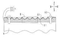
- FIG. 2 is a sectional view taken along line II-II of FIG. 1. It is an enlarged view of the dashed-dotted line frame III of FIG. It is a partial cross-sectional enlarged view of the heat dissipation member of 2nd embodiment. It is a schematic sectional drawing of the experimental apparatus used in the heat dissipation experiment. It is a graph which plotted the temperature difference with respect to the thermal resistance of a protective layer (heat conductivity of a heat dissipation layer: 0.78 W/mK).
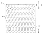
- FIG. 1 shows a top view of the heat dissipation member of the present embodiment.
- FIG. 2 shows a sectional view taken along line II-II of FIG.
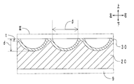
- FIG. 3 shows an enlarged view of the one-dot chain line frame III in FIG.
- hatching of the motor and the clip member is omitted in FIG.
- the azimuths in FIGS. 1 to 3 define the stacking direction of the two layers forming the heat dissipation member as the vertical direction.
- the heat dissipation member 1 has a square plate shape. As shown in FIGS. 1 and 2, the heat dissipation member 1 is attached to the surface of the motor 9 that is a noise source by a clip member 90.
- the motor 9 is included in the concept of the "counterpart member" in the present invention.
- the heat dissipation member 1 has a heat dissipation layer 20 and a protective layer 30.
- the heat dissipation layer 20 is arranged in contact with the motor 9.
- the maximum thickness of the heat dissipation layer 20 is 4.5 mm.
- the heat dissipation layer 20 has a base material made of polyurethane foam and composite particles in which graphite particles are combined with stainless steel particles.
- the composite particles are oriented so as to be continuous in the thickness direction of the heat dissipation layer 20 (the stacking direction, the vertical direction).
- the thermal conductivity of the heat dissipation layer 20 in the stacking direction (vertical direction) is 0.78 W/mK.
- Polyurethane foam is included in the concept of the polymer constituting the heat dissipation layer in the present invention.
- the composite particles are included in the concept of the magnetic filler forming the heat dissipation layer in the present invention.
- the protective layer 30 is stacked above the heat dissipation layer 20.
- the protective layer 30 is made of an embossed aluminum plate.
- the vertical cross section of the protective layer 30 has an uneven shape.
- the thermal conductivity of the protective layer 30 in the stacking direction (vertical direction) is 240 W/mK.
- one surface on the heat dissipation layer 20 side is a back surface 31, and one surface opposite to the heat dissipation layer 20 is a front surface 32.
- the back surface 31 is an uneven surface having a plurality of convex portions that project downward (to the heat dissipation layer 20 side) with respect to the flat plate
- the front surface 32 has a plurality of concave portions that are recessed downward with respect to the flat plate. It is an uneven surface having.
- the opening of the recess of the protective layer 30 has a circular shape when viewed from above.
- the protective layer 30 has a thickness t of 0.5 mm, an uneven height d of 1.3 mm, and a recess diameter ⁇ of 3.2 mm. Both the back surface 31 and the front surface 32 are anodized and have a black color.
- the area of the surface 32 is 1.15 times the projected area of the protective layer 30 in the stacking direction (surface area when the protective layer 30 is regarded as a flat plate shape).
- the thermal resistance of the protective layer 30 calculated by the above formula (I) is 2.08 ⁇ 10 ⁇ 6 m 2 K/W.
- the heat dissipation member 1 is manufactured by an integral molding method.
- a heat dissipation layer material is prepared by mixing a urethane foam resin material, composite particles, a foaming agent, a catalyst and the like.
- the aluminum plate for the protective layer 30 (embossed and black alumite treated) prepared in advance is placed in the mold with the surface 32 facing the mold surface and clamped.
- the material for the heat dissipation layer is injected into the cavity of the mold, and integrally molded while applying a magnetic field in the thickness direction of the cavity. In this way, the heat dissipation member 1 in which the heat dissipation layer 20 and the protective layer 30 (aluminum plate) are integrated is manufactured.
- the heat dissipation layer 20 has a base material made of polyurethane foam and composite particles oriented in the stacking direction.
- the heat of the motor 9 is dissipated through the composite particles in the heat dissipation layer 20, and the radiated sound is absorbed and shielded by the heat dissipation layer 20.
- a protective layer 30 is laminated on the upper surface (outer side) of the heat dissipation layer 20. Thereby, the heat dissipation layer 20 can be protected from the outside, and the heat dissipation member 1 can be easily attached to the motor 9 using the clip member 90.
- the protective layer 30 has a large thermal conductivity and a small thermal resistance. Therefore, the protective layer 30 is less likely to impair the heat dissipation of the heat dissipation layer 20.
- the protective layer 30 is made of an aluminum plate, and the back surface 31 and the front surface 32 are black alumite treated. This increases the emissivity of the protective layer 30, which is advantageous for improving heat dissipation.
- the surface 32 has a plurality of recesses, and the area thereof is 1.15 times as large as when the protective layer 30 is formed in a flat plate shape. Since the heat transfer area is large, the heat dissipation of the protective layer 30 becomes higher.
- the back surface 31 has a plurality of protrusions protruding toward the heat dissipation layer 20. This increases the contact area with the heat dissipation layer 20, which facilitates heat conduction and is advantageous in improving heat dissipation, and also improves the adhesiveness between the heat dissipation layer 20 and the protective layer 30.
- the heat dissipation member 1 is manufactured by an integral molding method. Therefore, as compared with the case where the heat dissipation layer 20 and the protective layer 30 are bonded to each other with an adhesive or the like, the thermal resistance between the two layers becomes smaller, which is advantageous in improving heat dissipation. As described above, according to the heat dissipation member 1, the attachment property and the durability can be improved without impairing the heat dissipation property of the heat dissipation layer 20.
- FIG. 4 shows a partially enlarged cross-sectional view of the heat dissipation member of this embodiment.
- the heat conductive filler is exaggerated in FIG. FIG. 4 corresponds to the above-described FIG. 3 (enlarged view of the one-dot chain line frame III in FIG. 2). 4, the same members as those in FIG. 3 are designated by the same reference numerals.
- the heat dissipation member 1 includes a heat dissipation layer 20, a protective layer 33, and a heat conductive filler 40.
- the protective layer 33 is stacked above the heat dissipation layer 20.
- the material of the protective layer 33 is the same as that of the protective layer 30 of the first embodiment. That is, the protective layer 33 is made of an embossed aluminum plate, and the back surface 34 and the front surface 35 are both alumite treated to be black.
- the vertical cross section of the protective layer 33 has an uneven shape.
- the thermal conductivity of the protective layer 33 in the stacking direction (vertical direction) is 240 W/mK.
- the back surface 34 is an uneven surface having a plurality of recesses that are recessed upward with respect to the flat plate.
- the surface 35 is an uneven surface having a plurality of convex portions that project upward with respect to the flat plate.
- the opening of the recess has a diamond shape.
- the protective layer 33 has a thickness t of 0.5 mm and an uneven height d of 1.3 mm.
- the area of the surface 35 is 1.08 times the projected area of the protective layer 33 in the stacking direction (surface area when the protective layer 35 is regarded as a flat plate).
- the thermal resistance of the protective layer 33 calculated by the above formula (I) is 2.08 ⁇ 10 ⁇ 6 m 2 K/W, which is the same as that of the protective layer 30 of the first embodiment.
- the heat conductive filler 40 is arranged in the recess on the back surface 34 side of the protective layer 33. In the recess, the heat conductive filler 40 is interposed between the heat dissipation layer 20 and the protective layer 33.
- the heat conductive filler 40 is aluminum hydroxide particles.
- the heat dissipation member of the present embodiment is also manufactured by the integral molding method, similarly to the heat dissipation member of the first embodiment.
- a heat dissipation layer material is prepared by mixing a urethane foam resin material, composite particles, a foaming agent, a catalyst and the like.
- an aluminum plate (embossed and black-anodized) that has been prepared in advance for the protective layer 33 is placed in the molding die with the surface 35 facing the mold surface.
- the heat conductive filler 40 is arranged in the concave portion of the back surface 34 of the aluminum plate.
- the material for the heat dissipation layer is injected into the cavity of the molding die and integrally molded while applying a magnetic field in the thickness direction of the cavity.
- the heat dissipation layer 20 and the protective layer 33 are integrated, and a heat dissipation member having the heat conductive filler 40 between both layers is manufactured.
- the heat dissipating member of the present embodiment has the same function and effect as the heat dissipating member of the first embodiment with respect to the portions having the same configuration.
- the heat conductive filler 40 is interposed between the heat dissipation layer 20 and the protective layer 33. Since the heat conductive filler is interposed, the amount of heat transferred between the heat dissipation layer 20 and the protective layer 33 is increased, and heat dissipation can be improved.
- the protective layer 33 has an uneven shape, it is easy for air to be entrapped during the integral molding and voids (air bubbles) are easily formed in the recesses. If there is a void in the recess, it becomes a thermal resistance and hinders heat dissipation.
- the thermally conductive filler is arranged in the concave portion of the protective layer 33 and integrally molded. Thereby, the generation of voids can be suppressed.
- the heat dissipation member has a square shape, but the shape of the heat dissipation member may be appropriately determined according to the shape of the counterpart member that is the object of heat dissipation.
- the heat dissipation member may cover a part of the mating member or may cover the entire member.
- Counterpart members include various parts such as inverters for electric power trains, motors, gearboxes, vehicle parts such as engine cylinder heads and cylinder head covers, electronic parts such as semiconductor elements, electric pumps, electric compressors, etc.
- the heat dissipation layer only needs to have a polymer, and does not necessarily need to include the magnetic filler (composite particles) as in the above embodiment.
- the polymer may be foamed or solid.
- foamed resin or foamed elastomer such as polyurethane foam, polyethylene foam and polypropylene foam may be mentioned.
- crosslinked rubbers such as urethane rubber, silicone rubber, fluororubber, acrylic rubber, acrylonitrile butadiene rubber, styrene-based, olefin-based, vinyl chloride-based, polyester-based, polyurethane-based and polyamide-based various thermoplastic elastomers can be mentioned. ..
- the magnetic filler When a magnetic filler is added to the polymer and the magnetic filler is oriented in the stacking direction, the heat of the mating member is rapidly released through the magnetic filler that is continuous in the stacking direction. Therefore, the inclusion of the magnetic filler in the polymer is effective in improving the heat dissipation.
- the magnetic filler include ferromagnets such as iron, nickel, cobalt, gadolinium, and stainless steel, antiferromagnets such as MnO, Cr 2 O 3 , FeCl 2 , and MnAs, and particles of alloys using these. Should be used.
- stainless steel particles, copper iron alloy particles and the like are preferable because they have high thermal conductivity and are excellent in workability as a filler.
- composite particles in which magnetic particles are attached to the surface of thermally conductive particles having high thermal conductivity may be used as in the above embodiment.
- a material of the heat conductive particles for example, a carbon material such as graphite, expanded graphite or carbon fiber is suitable.
- the magnetic particles particles suitable as a magnetic filler may be used.
- the thermal conductivity of the heat dissipation layer in the stacking direction is 0.3 W/mK or more and 3.0 W/mK or less. When it is 0.7 W/mK or more, heat dissipation is improved, which is preferable.
- the thickness of the heat dissipation layer is not particularly limited. The thickness of the heat dissipation layer is preferably 2 mm or more and 10 mm or less from the viewpoints of reducing heat resistance, being easy to mold, having appropriate strength and being excellent in handleability.
- the material of the protective layer is not particularly limited.
- metal, resin, elastomer and the like can be mentioned.
- Metals have the advantage of relatively high thermal conductivity.
- Resins and elastomers have the advantage of being easy to make the surface uneven and to form a thin film.
- the metal include aluminum, aluminum alloy, copper, and stainless steel.
- the resin include polyurethane resin, polyamide (PA) resin such as nylon 66, ABS resin, polypropylene (PP) resin, etc., and elastomer such as urethane rubber and silicone. Examples thereof include rubber and various thermoplastic elastomers.
- a material in which various reinforcing materials such as glass fiber are blended therein, or a composite material of these and other materials may be used.
- the surface of the protective layer may be surface-treated.
- the surface may be black-anodized.
- corrosion resistance and wear resistance are improved, and by making the surface black, emissivity is increased and heat dissipation can be improved.
- the material (thermal conductivity) and thickness of the protective layer may be determined so that the thermal resistance falls within the above range.
- the thickness of the protective layer is preferably 0.3 mm or more and 2.0 mm or less.
- the thickness of the protective layer is preferably 1.0 mm or more and 3.0 mm or less.
- the shape of the protective layer is not particularly limited. As in the above-described embodiment, it may have an uneven shape or a flat plate shape having a flat front and back surfaces.
- the two surfaces of the protective layer in the stacking direction when one surface on the heat dissipation layer side is the back surface and one surface on the opposite side to the heat dissipation layer is the front surface, at least one of the back surface and the front surface is at least one of the concave portion and the convex portion. It is desirable that the surface has an uneven surface.
- the surface area of the uneven surface is preferably 1.04 times or more and 1.60 times or less the projected area of the protective layer in the stacking direction.
- the surface area is less than 1.04 times, the effect of improving heat dissipation is small.
- the surface area exceeds 1.60 times, it becomes difficult to form the uneven shape by embossing.
- the “projected area of the protective layer in the stacking direction” is equal to the surface area when it is considered that the surface of the protective layer has no unevenness.
- the contact area with the heat dissipation layer is increased, so that the heat dissipation is enhanced and the adhesiveness between the heat dissipation layer and the protective layer is improved.
- the arrangement form, shape, size, etc. of the concave portion and the convex portion are not particularly limited.
- the concave portions or the convex portions may be scattered in the surface direction, or may be a groove portion, a protrusion, or the like extending in a predetermined direction.
- the cross-sectional shape is also not particularly limited, such as a semicircular shape, a semielliptical shape, a triangular shape, a square shape, a rectangular shape, and a trapezoidal shape.
- various embossed patterns can be formed on the front surface and the back surface by embossing the material forming the protective layer.
- voids air bubbles
- it becomes a thermal resistance and hinders heat dissipation.
- a heat conductive filler in the concave portion on the back surface of the protective layer as in the second embodiment.
- Particles having a thermal conductivity of 20 W/mK or more may be used as the thermally conductive filler.
- the thermally conductive filler For example, aluminum hydroxide, magnesium oxide, boron nitride, carbon materials such as graphite, expanded graphite, carbon fiber, aluminum, magnesium, gold, silver, copper and alloys having these as base materials, or oxides thereof, etc. It is suitable.
- the shape of the heat conductive filler is not particularly limited, and may be spherical, flaky, fibrous, or columnar.
- the manufacturing method of the heat dissipation member is not particularly limited.
- a protective layer may be attached to the surface of the heat dissipation layer with an adhesive or the like.
- the protective layer is made of a resin or an elastomer, first, the protective layer raw material is injected into the molding die for molding, and then the heat dissipation layer raw material is injected, and molding is performed while applying a magnetic field, or Alternatively, the material for the heat dissipation layer may be injected into the molding die, and the material may be molded while applying a magnetic field, and then the material for the protective layer may be injected to perform molding (two-step molding method).
- the material for the protective layer may be applied to the surface of the heat dissipation layer by spraying or the like and dried.
- the latter coating method is suitable for forming a thin film protective layer.
- the coating method by forming the surface of the heat dissipation layer in an uneven shape, the uneven protection layer can be easily formed.
- the integral molding method, the two-step molding method, the coating method, etc. since the heat dissipation layer and the protective layer can be fixed without using an adhesive, the thermal resistance between the two layers becomes small, which is advantageous for improving heat dissipation. Is.
- the first protective layer has a square flat plate shape having a length of 130 mm, a width of 130 mm, and a thickness of 0.5 mm.
- the front surface and the back surface of the first protective layer are flat surfaces without irregularities.
- the surface area of the first protective layer is 1.69 ⁇ 10 ⁇ 2 m 2 .
- the second protective layer has a square flat plate shape having the same size as that of the first protective layer, but is different in that the front surface and the back surface are uneven due to embossing.
- the second protective layer has the same size and shape as the protective layer of the second embodiment (see FIG. 4 above). That is, the back surface of the second protective layer is an uneven surface having a plurality of concave portions recessed upward with respect to the flat plate, and the surface is an uneven surface having a plurality of convex portions protruding upward with respect to the flat plate.
- the surface area of the second protective layer is 1.82 ⁇ 10 ⁇ 2 m 2 .
- the area ratio of the surface of the second protective layer is 1.08 times when the surface area of the flat first protective layer having no unevenness is taken as the reference (1.00).
- the third protective layer has a square flat plate shape having the same size as that of the first protective layer, but is different in that the front surface and the back surface are uneven due to embossing.
- the third protective layer has the same size and shape as the protective layer of the first embodiment (see FIG. 3 above). That is, the back surface of the third protective layer is an uneven surface having a plurality of convex portions protruding downward with respect to the flat plate, and the surface is an uneven surface having a plurality of concave portions depressed downward with respect to the flat plate. is there.
- the surface area of the third protective layer is 1.95 ⁇ 10 ⁇ 2 m 2 .
- the area ratio of the surface of the third protective layer is 1.15 times when the surface area of the flat first protective layer having no unevenness is used as a reference (1.00).
- the projected area is 1.69 ⁇ 10 ⁇ 2 m 2
- the thermal conductivity in the thickness direction is 240 W/mK
- the thermal resistance is 2.08 ⁇ 10 ⁇ . It is 6 m 2 K/W.
- the thickness of the first protective layer is 2.5 mm, the thermal conductivity in the thickness direction is 0.34 W/mK, and the thermal resistance is 7.35 ⁇ 10 ⁇ 3 m 2 K/W.
- the thickness of the second protective layer is 3.5 mm, the thermal conductivity in the thickness direction is 0.34 W/mK, and the thermal resistance is 1.03 ⁇ 10 ⁇ 2 m 2 K/W.
- the first protective layer has a square flat plate shape having a length of 130 mm, a width of 130 mm, and a thickness of 2.0 mm.
- the front surface and the back surface of the first protective layer are flat surfaces without irregularities.
- the surface area of the first protective layer is 1.69 ⁇ 10 ⁇ 2 m 2 .
- the second protective layer has a square flat plate shape having the same size as that of the first protective layer, but since it is molded by using a mold having an uneven shape, the front and back surfaces are uneven. Is different.
- the second protective layer has the same size (only the thickness is different) and shape as the protective layer of the first embodiment (see FIG. 3 described above). That is, the back surface of the second protective layer is an uneven surface having a plurality of convex portions projecting downward with respect to the flat plate, and the surface is an uneven surface having a plurality of concave portions depressed downward with respect to the flat plate. is there.
- the surface area of the second protective layer is 1.95 ⁇ 10 ⁇ 2 m 2 .
- the area ratio of the surface of the second protective layer is 1.15 times when the surface area of the plate-shaped first protective layer having no unevenness is used as a reference (1.00).
- the projected area was 1.69 ⁇ 10 ⁇ 2 m 2
- the thermal conductivity in the thickness direction was 0.24 W/mK
- the thermal resistance was 8.33 ⁇ 10 ⁇ 3 m 2 K. /W.
- Table 1 summarizes the specifications of the protective layer.
- Heat dissipation member A heat dissipation layer was integrated with each protective layer to manufacture a heat dissipation member.
- For the aluminum protective layer place the protective layer on the mold with the surface facing the mold surface and clamp the mold, then inject the heat-dissipating layer raw material into the cavity of the mold to determine the thickness of the cavity. It was molded integrally while applying a magnetic field in the direction.
- the protective layer made of nylon 66 resin and polyurethane resin containing 30% by mass of glass fiber, first, the raw material for the protective layer is injected into the cavity of the molding die to form the protective layer, and then the raw material for the heat dissipation layer is injected. Molding was performed while applying a magnetic field in the thickness direction of the cavity (two-stage molding method). In this way, a sheet-shaped heat dissipation member in which the heat dissipation layer and the protective layer were laminated was manufactured.
- the material for the heat dissipation layer was prepared as follows. First, a polyether raw material, a crosslinking agent, water as a foaming agent, a catalyst, and a foam stabilizer were mixed to prepare a polyol raw material. Next, the premixed polyol was prepared by adding and mixing, to the prepared polyol raw material, composite particles in which graphite particles were composited with stainless steel particles and a plasticizer. Then, the premix polyol and the polyisocyanate raw material were mixed to obtain a raw material for the heat dissipation layer. As the protective layer, four types of heat dissipation layers having different thermal conductivities in the thickness direction (laminating direction) were appropriately combined.
- the thermal conductivity of the four types of heat dissipation layers is 0.1 W/mK, 0.3 W/mK, 0.78 W/mK, and 3.0 W/mK.
- the thermal conductivity of the heat dissipation layer was adjusted by changing the compounding amount of the composite particles.
- FIG. 5 shows a schematic sectional view of the experimental apparatus.
- the experimental apparatus 5 includes a support base 50, a rubber heater 51, a heating plate 52, and a thermocouple 53.
- the rubber heater 51 has a rectangular sheet shape and is horizontally arranged on the support base 50.
- the rubber heater 51 is connected to a temperature controller (not shown) by the wiring 510, and a constant heat amount of 0.2 W/cm 2 is supplied from the temperature controller.
- the heating plate 52 is made of aluminum and has a rectangular plate shape.
- the heating plate 52 is arranged on the upper surface of the rubber heater 51.
- the thermocouple 53 is arranged in the center of the upper surface of the heating plate 52. The upper surface temperature of the heating plate 52 is measured by the thermocouple 53.
- the manufactured heat dissipation member 54 was placed on the heating plate 52 with the protective layer facing upward, and a heat dissipation experiment was performed to measure the change with time of the upper surface temperature of the heating plate 52.
- the heat radiation experiment was performed under the condition of forced convection by blowing air from the side of the experimental apparatus 5. Then, the temperature at which the change in temperature became small and became almost constant was adopted as the final temperature.
- the time-dependent change in the upper surface temperature of the heating plate 52 was measured without disposing the heat dissipation member 54 to obtain the final temperature.
- the temperature difference was determined by subtracting the final temperature without the heat dissipation member 54 from the final temperature with the heat dissipation member 54. The smaller the temperature difference, the greater the heat dissipation effect of the heat dissipation member 54.
- FIG. 6 shows a graph plotting the temperature difference against the thermal resistance of the protective layer as an experimental result of the heat radiating member in which various protective layers are combined with a heat radiating layer having a thermal conductivity of 0.78 W/mK.
- the plot with the thermal resistance of 2.08 ⁇ 10 ⁇ 6 m 2 K/W is the result of the “aluminum protective layer”, and the thermal resistance is 8.33 ⁇ 10.
- FIG. 7 shows a graph plotting the temperature difference with respect to the area ratio of the protective layer as an experimental result of the heat radiating member in which various protective layers are combined with a heat radiating layer having a thermal conductivity of 0.78 W/mK.
- the thermal resistance of the “aluminum” protective layer is 2.08 ⁇ 10 ⁇ 6 m 2 K/W
- the thermal resistance of the “nylon 66 resin” protective layer is 7.35 ⁇ 10 ⁇ 3.
- m 2 K/W and the thermal resistance of the protective layer made of “polyurethane resin” is 8.33 ⁇ 10 ⁇ 3 m 2 K/W.
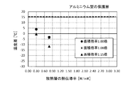
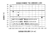
- FIG. 3 is a graph in which the temperature difference is plotted against the thermal conductivity of the heat dissipation layer.
- the case where the temperature difference was 15° C. or less was evaluated as “good heat dissipation”.
- a thick dotted line indicates a line with a temperature difference of 15° C., which serves as a reference for heat dissipation.
- FIG. 9 shows a graph in which the temperature difference is plotted against the thermal conductivity of the heat dissipation layer as an experimental result of the heat dissipation member in which the heat dissipation layers of mK and 3.00 W/mK are combined. Similar to FIG. 8, in FIG. 9, a line with a temperature difference of 15° C., which serves as a reference for the heat radiation property, is indicated by a thick dotted line.
- the thermal conductivity of the heat dissipation layer is 0.3 W/mK or more and 3.0 W/mK or less, and the thermal resistance of the protective layer is 2.0 ⁇ 10 ⁇ 6 m 2 K/W or more 1.5 ⁇ . It was confirmed that the heat-dissipating member of the present invention having 10 ⁇ 2 m 2 K/W or less has excellent heat dissipation.
- the heat dissipating member of the present invention requires heat dissipating properties such as inverters of electric power trains, motors, gearboxes, vehicle parts such as engine cylinder heads and cylinder head covers, electronic parts such as semiconductor elements, electric pumps and electric compressors. It is suitable for various uses.
- heat dissipation member 20: heat dissipation layer, 30: protection layer, 31: back surface, 32: front surface, 33: protection layer, 34: back surface, 35: front surface, 40: heat conductive filler, 5: experimental device, 50: Support base, 51: rubber heater, 52: heating plate, 53: thermocouple, 54: heat dissipation member, 510: wiring, 9: motor (counterpart member), 90: clip member.
Landscapes
- Physics & Mathematics (AREA)
- Thermal Sciences (AREA)
- Engineering & Computer Science (AREA)
- Microelectronics & Electronic Packaging (AREA)
- Cooling Or The Like Of Semiconductors Or Solid State Devices (AREA)
- Cooling Or The Like Of Electrical Apparatus (AREA)
- Laminated Bodies (AREA)
Abstract
放熱部材(1)は、ポリマーを有する放熱層(20)と、放熱層(20)に積層される保護層(30)と、を備える。放熱層(20)は相手部材(9)に接触して配置され、積層方向の熱伝導率は0.3W/mK以上3.0W/mK以下である。次式(I)により算出される保護層(30)の熱抵抗は、2.0×10-6m2K/W以上1.5×10-2m2K/W以下である。 保護層の熱抵抗=L/k ・・・(I) [L:保護層の積層方向の厚さ(m)、k:保護層の積層方向の熱伝導率(W/mK)]
Description
本発明は、熱源の周囲に取り付けて、熱源の熱を外部に放出するための放熱部材に関する。
車室内の静粛性向上の要求が高まるなか、エンジン、モータなどの駆動装置やトランスミッションなどの動力伝達装置から発生する騒音の低減対策が講じられている。近年では電気自動車(EV)化やハイブリッド電気自動車(HEV)化が進められていることから、インバータ、モータ、ギアボックスなどからなる電動パワートレインの駆動音も低減の対象になる。騒音対策としては、例えば、ポリウレタンフォームなどの発泡体からなる防音材が用いられる。しかし、発泡体は、内部に多数のセル(気泡)を有するため熱伝導率が小さい。このため、発熱を伴う騒音源の周囲に配置した場合、熱が蓄積され不具合を生じるおそれがある。したがって、発泡体を用いた防音材の放熱性を向上させるという観点から、例えば特許文献1、2には、発泡体に磁性フィラーを含有させた防音材が開示されている。特許文献1、2に記載された防音材においては、熱伝導率が大きな磁性フィラーが、防音材の厚さ方向に配向している。このため、騒音を低減できるだけでなく、騒音源で生じた熱を、配向した磁性フィラーを介して速やかに放出することができる。
発泡体などのポリマーを用いた防音材の場合、それを騒音源などに取り付けるために、硬質のカバー部材を用いることがある。例えば、特許文献1の図1、特許文献2の図7などに示されるように、カバー部材は防音材の外側を被覆するように配置される。また、車両の走行中に巻き上げられた砂や小石から防音材を保護するために、防音材の外側を硬質のカバー部材で被覆することもある。しかしながら、防音材をカバー部材で被覆すると、カバー部材の分だけ熱抵抗が増えるため、防音材の放熱性が低下するおそれがある。
本発明は、このような実情に鑑みてなされたものであり、放熱性を損なうことなく、取り付け性および耐久性を満足する放熱部材を提供することを課題とする。
上記課題を解決するため、本発明の放熱部材は、ポリマーを有する放熱層と、該放熱層に積層される保護層と、を備え、該放熱層は相手部材に接触して配置され、積層方向の熱伝導率は0.3W/mK以上3.0W/mK以下であり、次式(I)により算出される該保護層の熱抵抗は、2.0×10-6m2K/W以上1.5×10-2m2K/W以下であることを特徴とする。
保護層の熱抵抗=L/k ・・・(I)
[L:保護層の積層方向の厚さ(m)、k:保護層の積層方向の熱伝導率(W/mK)]
保護層の熱抵抗=L/k ・・・(I)
[L:保護層の積層方向の厚さ(m)、k:保護層の積層方向の熱伝導率(W/mK)]
本発明の放熱部材は、放熱層と保護層とを備える。本発明における「積層方向」は、放熱層と保護層との重なり方向である。放熱層は、放熱対象の相手部材に接触して配置される。積層方向における放熱層の熱伝導率は0.3W/mK以上3.0W/mK以下であり、放熱層は相手部材の熱を熱伝導により外部に放熱させる放熱作用を有する。加えて、放熱層はポリマーを有し、相手部材からの放射音を吸収、遮蔽する防音作用も有する。
放熱層には、保護層が積層される。すなわち、放熱層における相手部材とは反対側の表面は、保護層で被覆される(必ずしも放熱層の表面全体が被覆される形態だけではなく、放熱層の表面の一部が被覆される形態を含む)。保護層を配置することにより、外部から放熱層を保護することができると共に、相手部材などに放熱部材を取り付けやすくなる。ここで、積層方向における保護層の熱抵抗は、2.0×10⁻⁶m2K/W以上1.5×10-2m2K/W以下と小さい。このため、保護層で被覆されても、放熱層の放熱性は阻害されにくい。また、放熱層と保護層という固有振動数が異なる二層が積層されることにより、制振性が向上して、防音性が向上する可能性もある。
このように、本発明の放熱部材によると、放熱層の放熱性を損なうことなく、取り付け性および耐久性を向上させることができる。
放熱性を有するシート部材としては、例えば特許文献3に、熱伝導性フィラーを含有するゴム系発泡シートと、その一面に配置される金属系薄膜と、を備える発泡複合シートが開示されている。特許文献3においては、放熱性に加えて導電性および電磁波シールド性を付与するために、ゴム系発泡シートの一面に金属系薄膜を形成している(段落[0006])。また、特許文献3の段落[0018]には、「発泡複合シートでは、金属系薄膜により、発泡シートの面方向に沿って熱伝導するため、熱源による局所的な過熱を分散させやすくなる。」と記載されている。このように、特許文献3では、積層方向(発泡シートの厚さ方向)における熱伝導に着目しておらず、同方向における金属系薄膜の熱抵抗について何も検討していない。また、金属系薄膜は、スパッタリングや蒸着により形成されるため(段落[0032])、その厚さは極めて薄い。よって、特許文献3には、金属系薄膜によりゴム系発泡シートを保護したり、取り付けを容易にするという思想もない。
以下、本発明の放熱部材の実施の形態について説明する。
<第一実施形態>
[構成]
まず、本実施形態の放熱部材の構成を説明する。図1に、本実施形態の放熱部材の上面図を示す。図2に、図1のII-II断面図を示す。図3に、図2の一点鎖線枠IIIの拡大図を示す。説明の便宜上、図2においては、モータおよびクリップ部材のハッチングを省略して示す。図1~図3の方位は、放熱部材を構成する二層の積層方向を上下方向として定義している。
[構成]
まず、本実施形態の放熱部材の構成を説明する。図1に、本実施形態の放熱部材の上面図を示す。図2に、図1のII-II断面図を示す。図3に、図2の一点鎖線枠IIIの拡大図を示す。説明の便宜上、図2においては、モータおよびクリップ部材のハッチングを省略して示す。図1~図3の方位は、放熱部材を構成する二層の積層方向を上下方向として定義している。
図1に示すように、放熱部材1は、正方形板状を呈している。図1、図2に示すように、放熱部材1は、騒音源であるモータ9の表面に、クリップ部材90により取り付けられている。モータ9は、本発明における「相手部材」の概念に含まれる。
図2、図3に示すように、放熱部材1は、放熱層20と、保護層30と、を有している。放熱層20は、モータ9に接触して配置されている。放熱層20の最大厚さは、4.5mmである。放熱層20は、ポリウレタンフォームからなる母材と、黒鉛粒子にステンレス鋼粒子を複合化した複合粒子と、を有している。複合粒子は、放熱層20の厚さ方向(積層方向、上下方向)に連なるように配向している。放熱層20の積層方向(上下方向)の熱伝導率は0.78W/mKである。ポリウレタンフォームは、本発明における放熱層を構成するポリマーの概念に含まれる。複合粒子は、本発明における放熱層を構成する磁性フィラーの概念に含まれる。
保護層30は、放熱層20の上方に積層されている。保護層30は、エンボス加工されたアルミニウム板からなる。保護層30の上下方向断面は、凹凸形状を呈している。保護層30の積層方向(上下方向)の熱伝導率は、240W/mKである。保護層30の積層方向(上下方向)の二面のうち、放熱層20側の一面を裏面31、放熱層20とは反対側の一面を表面32とする。この場合、裏面31は、平板に対して下側(放熱層20側)に突出する複数の凸部を有する凹凸面であり、表面32は、平板に対して下側に窪んだ複数の凹部を有する凹凸面である。図1に示すように、上方から見て、保護層30の凹部の開口部は円状を呈している。図3に示すように、保護層30の厚さtは0.5mm、凹凸高さdは1.3mm、凹部直径φは3.2mmである。裏面31および表面32は、いずれもアルマイト処理されており黒色を呈している。表面32の面積は、保護層30の積層方向の投影面積(保護層30を平板状とみなした時の表面積)の1.15倍である。前述の式(I)により算出される保護層30の熱抵抗は、2.08×10-6m2K/Wである。
[製造方法]
次に、本実施形態の放熱部材の製造方法について説明する。放熱部材1は、一体成形法により製造される。まず、発泡ウレタン樹脂原料、複合粒子、発泡剤、触媒などを混合した放熱層用原料を調製する。次に、予め準備しておいた保護層30用のアルミニウム板(エンボス加工および黒色アルマイト処理済み)を、表面32が型面側になるようにして成形型に配置して型締めする。それから、放熱層用原料を成形型のキャビティに注入し、キャビティの厚さ方向に磁場を作用させながら一体成形する。このようにして、放熱層20と保護層30(アルミニウム板)とが一体化した放熱部材1が製造される。
次に、本実施形態の放熱部材の製造方法について説明する。放熱部材1は、一体成形法により製造される。まず、発泡ウレタン樹脂原料、複合粒子、発泡剤、触媒などを混合した放熱層用原料を調製する。次に、予め準備しておいた保護層30用のアルミニウム板(エンボス加工および黒色アルマイト処理済み)を、表面32が型面側になるようにして成形型に配置して型締めする。それから、放熱層用原料を成形型のキャビティに注入し、キャビティの厚さ方向に磁場を作用させながら一体成形する。このようにして、放熱層20と保護層30(アルミニウム板)とが一体化した放熱部材1が製造される。
[作用効果]
次に、本実施形態の放熱部材の作用効果を説明する。放熱部材1において、放熱層20は、ポリウレタンフォームからなる母材と積層方向に配向された複合粒子とを有している。放熱層20がモータ9に接触して配置されることにより、モータ9の熱は放熱層20中の複合粒子を介して放熱され、放射音は放熱層20で吸収、遮蔽される。放熱層20の上面(外側)には、保護層30が積層されている。これにより、外部から放熱層20を保護することができると共に、クリップ部材90を用いて放熱部材1をモータ9に容易に取り付けることができる。
次に、本実施形態の放熱部材の作用効果を説明する。放熱部材1において、放熱層20は、ポリウレタンフォームからなる母材と積層方向に配向された複合粒子とを有している。放熱層20がモータ9に接触して配置されることにより、モータ9の熱は放熱層20中の複合粒子を介して放熱され、放射音は放熱層20で吸収、遮蔽される。放熱層20の上面(外側)には、保護層30が積層されている。これにより、外部から放熱層20を保護することができると共に、クリップ部材90を用いて放熱部材1をモータ9に容易に取り付けることができる。
保護層30の熱伝導率は大きく熱抵抗は小さい。このため、保護層30は、放熱層20の放熱性を阻害しにくい。保護層30はアルミニウム板からなり、裏面31および表面32は黒色アルマイト処理されている。これにより、保護層30の放射率が大きくなり、放熱性の向上に有利である。また、表面32は複数の凹部を有しており、その面積は、保護層30を平板状に形成した場合の1.15倍である。伝熱面積が大きいため、保護層30の放熱性はより高くなる。他方、裏面31は、放熱層20側に突出する複数の凸部を有している。これにより、放熱層20との接触面積が大きくなるため、熱伝導しやすく放熱性の向上に有利であると共に、放熱層20と保護層30との接着性が向上する。
放熱部材1は、一体成形法により製造されている。このため、放熱層20と保護層30とを接着剤などにより接着させる場合と比較して、二層間の熱抵抗が小さくなり、放熱性の向上に有利である。このように、放熱部材1によると、放熱層20の放熱性を損なうことなく、取り付け性および耐久性を向上させることができる。
<第二実施形態>
[構成]
まず、本実施形態の放熱部材の構成を説明する。本実施形態の放熱部材と第一実施形態の放熱部材との構成における相違点は、保護層の形状が異なる点、熱伝導性フィラーが配置されている点の二点である。ここでは、相違点を中心に説明する。図4に、本実施形態の放熱部材の一部断面拡大図を示す。説明の便宜上、図4においては、熱伝導性フィラーを誇張して示す。図4は、前出の図3(図2の一点鎖線枠IIIの拡大図)に対応している。図4中、図3と同じ部材については同じ符号で示す。図4に示すように、放熱部材1は、放熱層20と、保護層33と、熱伝導性フィラー40と、を有している。
[構成]
まず、本実施形態の放熱部材の構成を説明する。本実施形態の放熱部材と第一実施形態の放熱部材との構成における相違点は、保護層の形状が異なる点、熱伝導性フィラーが配置されている点の二点である。ここでは、相違点を中心に説明する。図4に、本実施形態の放熱部材の一部断面拡大図を示す。説明の便宜上、図4においては、熱伝導性フィラーを誇張して示す。図4は、前出の図3(図2の一点鎖線枠IIIの拡大図)に対応している。図4中、図3と同じ部材については同じ符号で示す。図4に示すように、放熱部材1は、放熱層20と、保護層33と、熱伝導性フィラー40と、を有している。
保護層33は、放熱層20の上方に積層されている。保護層33の材質は、第一実施形態の保護層30と同じである。すなわち、保護層33は、エンボス加工されたアルミニウム板からなり、裏面34および表面35は、いずれもアルマイト処理されて黒色を呈している。保護層33の上下方向断面は、凹凸形状を呈している。保護層33の積層方向(上下方向)の熱伝導率は、240W/mKである。裏面34は、平板に対して上側に窪んだ複数の凹部を有する凹凸面である。表面35は、平板に対して上側に突出する複数の凸部を有する凹凸面である。保護層33を上方から見ると、凹部の開口部は菱形状を呈している。保護層33の厚さtは0.5mm、凹凸高さdは1.3mmである。表面35の面積は、保護層33の積層方向の投影面積(保護層35を平板状とみなした時の表面積)の1.08倍である。前述の式(I)により算出される保護層33の熱抵抗は、第一実施形態の保護層30と同じ2.08×10-6m2K/Wである。
熱伝導性フィラー40は、保護層33の裏面34側の凹部に配置されている。当該凹部において、熱伝導性フィラー40は、放熱層20と保護層33との間に介在されている。熱伝導性フィラー40は、水酸化アルミニウム粒子である。
[製造方法]
次に、本実施形態の放熱部材の製造方法について説明する。本実施形態の放熱部材も、第一実施形態の放熱部材と同様に、一体成形法により製造される。まず、発泡ウレタン樹脂原料、複合粒子、発泡剤、触媒などを混合した放熱層用原料を調製する。次に、予め準備しておいた保護層33用のアルミニウム板(エンボス加工および黒色アルマイト処理済み)を、表面35が型面側になるようにして成形型に配置する。続いて、アルミニウム板の裏面34の凹部に、熱伝導性フィラー40を配置する。型締め後、放熱層用原料を成形型のキャビティに注入し、キャビティの厚さ方向に磁場を作用させながら一体成形する。このようにして、放熱層20と保護層33(アルミニウム板)とが一体化し、両層の間に熱伝導性フィラー40を有する放熱部材が製造される。
次に、本実施形態の放熱部材の製造方法について説明する。本実施形態の放熱部材も、第一実施形態の放熱部材と同様に、一体成形法により製造される。まず、発泡ウレタン樹脂原料、複合粒子、発泡剤、触媒などを混合した放熱層用原料を調製する。次に、予め準備しておいた保護層33用のアルミニウム板(エンボス加工および黒色アルマイト処理済み)を、表面35が型面側になるようにして成形型に配置する。続いて、アルミニウム板の裏面34の凹部に、熱伝導性フィラー40を配置する。型締め後、放熱層用原料を成形型のキャビティに注入し、キャビティの厚さ方向に磁場を作用させながら一体成形する。このようにして、放熱層20と保護層33(アルミニウム板)とが一体化し、両層の間に熱伝導性フィラー40を有する放熱部材が製造される。
[作用効果]
次に、本実施形態の放熱部材の作用効果を説明する。本実施形態の放熱部材は、構成が共通する部分については、第一実施形態の放熱部材と同様の作用効果を有する。本実施形態の放熱部材によると、放熱層20と保護層33との間に、熱伝導性フィラー40が介在している。熱伝導性フィラーが介在することにより、放熱層20と保護層33との間の伝熱量が大きくなり、放熱性を向上させることができる。また、保護層33は凹凸形状を呈しているため、一体成形時に空気を巻き込みやすく、凹部にボイド(気泡)が形成されやすい。凹部にボイドが存在すると、それが熱抵抗になり放熱性を阻害する。この点、本実施形態の製造方法によると、保護層33の凹部に熱伝導性フィラーを配置して一体成形する。これにより、ボイドの生成を抑制することができる。
次に、本実施形態の放熱部材の作用効果を説明する。本実施形態の放熱部材は、構成が共通する部分については、第一実施形態の放熱部材と同様の作用効果を有する。本実施形態の放熱部材によると、放熱層20と保護層33との間に、熱伝導性フィラー40が介在している。熱伝導性フィラーが介在することにより、放熱層20と保護層33との間の伝熱量が大きくなり、放熱性を向上させることができる。また、保護層33は凹凸形状を呈しているため、一体成形時に空気を巻き込みやすく、凹部にボイド(気泡)が形成されやすい。凹部にボイドが存在すると、それが熱抵抗になり放熱性を阻害する。この点、本実施形態の製造方法によると、保護層33の凹部に熱伝導性フィラーを配置して一体成形する。これにより、ボイドの生成を抑制することができる。
<その他の実施形態>
以上、本発明の放熱部材の実施の形態について説明した。しかしながら、実施の形態は上記形態に特に限定されるものではない。当業者が行いうる種々の変形的形態、改良的形態で実施することも可能である。
以上、本発明の放熱部材の実施の形態について説明した。しかしながら、実施の形態は上記形態に特に限定されるものではない。当業者が行いうる種々の変形的形態、改良的形態で実施することも可能である。
上記実施形態においては、放熱部材を正方形状にしたが、放熱部材の形状は、放熱対象である相手部材の形状に応じて適宜決定すればよい。放熱部材は、相手部材の一部を被覆するものでもよく、全体を被覆するものでもよい。相手部材としては、電動パワートレインのインバータ、モータ、ギアボックスや、エンジンのシリンダヘッド、シリンダヘッドカバーなどの車両用部品の他、半導体素子などの電子部品、電動ポンプ、電動コンプレッサーなど種々の部材が挙げられる。
放熱層は、ポリマーを有すればよく、必ずしも上記実施形態のように磁性フィラー(複合粒子)を含まなくてもよい。ポリマーは、発泡体であってもソリッド体であってもよい。前者の場合、ポリウレタンフォーム、ポリエチレンフォーム、ポリプロピレンフォームなどの発泡樹脂または発泡エラストマーが挙げられる。後者の場合、ウレタンゴム、シリコーンゴム、フッ素ゴム、アクリルゴム、アクリロニトリルブタジエンゴムなどの架橋ゴム、スチレン系、オレフィン系、塩化ビニル系、ポリエステル系、ポリウレタン系、ポリアミド系の各種熱可塑性エラストマーが挙げられる。
ポリマーに磁性フィラーを加え、当該磁性フィラーを積層方向に配向させると、相手部材の熱は、積層方向に連なった磁性フィラーを介して速やかに放出される。よって、ポリマーに磁性フィラーを含有させることは、放熱性の向上に効果的である。磁性フィラーとしては、例えば、鉄、ニッケル、コバルト、ガドリニウム、ステンレス鋼などの強磁性体、MnO、Cr2O3、FeCl2、MnAsなどの反強磁性体、およびこれらを用いた合金類の粒子を用いるとよい。なかでも、熱伝導率が大きくフィラーとしての加工性に優れる点から、ステンレス鋼粒子、銅鉄合金粒子などが好適である。また、放熱性を向上させるという観点から、上記実施形態のように、熱伝導率が大きい熱伝導性粒子の表面に磁性粒子が付着した複合粒子を用いてもよい。熱伝導性粒子の材質としては、例えば、黒鉛、膨張黒鉛、炭素繊維などの炭素材料が好適である。磁性粒子としては、磁性フィラーとして好適な粒子を用いればよい。
積層方向における放熱層の熱伝導率は0.3W/mK以上3.0W/mK以下である。0.7W/mK以上であると、放熱性が向上するため好適である。放熱層の厚さは、特に限定されない。熱抵抗を小さくする、成形が容易である、適度な強度を有し取り扱い性に優れるという観点から、放熱層の厚さは2mm以上10mm以下であることが望ましい。
保護層の材質は、特に限定されない。例えば、金属、樹脂、エラストマーなどが挙げられる。金属は、熱伝導率が比較的大きいという利点がある。樹脂およびエラストマーは、表面を凹凸状にしたり、薄膜状に成形することが容易であるという利点がある。金属としては、アルミニウム、アルミニウム合金、銅、ステンレス鋼など、樹脂としては、ポリウレタン樹脂、ナイロン66などのポリアミド(PA)樹脂、ABS樹脂、ポリプロピレン(PP)樹脂など、エラストマーとしては、ウレタンゴム、シリコーンゴム、各種熱可塑性エラストマーなどが挙げられる。また、これらにガラス繊維などの各種強化材が配合された材料や、これらと他の材料との複合材料を用いてもよい。
用途に応じ、保護層の表面(放熱層とは反対側の面)に表面処理を施してもよい。例えば、アルミニウム、アルミニウム合金から保護層を形成する場合には、表面を黒色アルマイト処理しておくとよい。アルマイト処理により、耐食性、耐摩耗性が向上すると共に、表面を黒色にすることにより、放射率が大きくなり放熱性を高めることができる。
前述した式(I)[保護層の熱抵抗=L/k]により算出される保護層の熱抵抗は、2.0×10-6m2K/W以上1.5×10-2m2K/W以下である。式(I)に示されるように、保護層の厚さが小さいほど熱抵抗は小さくなり、保護層の熱伝導率が大きいほど熱抵抗は小さくなる。したがって、熱抵抗が上記範囲になるように、保護層の材質(熱伝導率)や厚さを決定すればよい。例えば、熱伝導率が200W/mK以上と比較的大きい金属から保護層を形成する場合には、保護層の厚さは0.3mm以上2.0mm以下であることが望ましい。反対に、熱伝導率が1.0W/mK未満と比較的小さい樹脂、エラストマーから保護層を形成する場合には、保護層の厚さは1.0mm以上3.0mm以下であることが望ましい。
保護層の形状は、特に限定されない。上記実施形態のように、凹凸形状でも、表面および裏面が平らな平板形状でもよい。例えば、積層方向における保護層の二面のうち、放熱層側の一面を裏面、放熱層とは反対側の一面を表面とした場合、裏面および表面の少なくとも一方は、凹部および凸部の少なくとも一方を複数有する凹凸面であることが望ましい。具体的な形態として、(a)表面のみに複数の凹部が配置される形態(裏面は平面)、(b)表面のみに複数の凸部が配置される形態(裏面は平面)、(c)裏面のみに複数の凹部が配置される形態(表面は平面)、(d)裏面のみに複数の凸部が配置される形態(表面は平面)、(e)表面および裏面に複数の凹部が配置される形態、(f)表面および裏面に複数の凸部が配置される形態、(g)表面に複数の凹部、裏面に複数の凸部が配置される形態(例えば第一実施形態)、(h)表面に複数の凸部、裏面に複数の凹部が配置される形態(例えば第二実施形態)が挙げられる。
外側に露出する表面の面積(表面積)が大きいほど、伝熱面積は大きくなる。このため、保護層の放熱性向上を図るには、少なくとも表面を凹凸面にして表面積を大きくすることが望ましい。この場合、凹凸面の表面積は、保護層の積層方向の投影面積の1.04倍以上1.60倍以下であるとよい。表面積が1.04倍未満であると、放熱性の向上効果が小さい。反対に、表面積が1.60倍を超えると、エンボス加工による凹凸形状の形成が難しくなる。なお、「保護層の積層方向の投影面積」は、保護層の表面に凹凸がないとみなした時の表面積に等しい。また、保護層の裏面に複数の凸部を配置すると、放熱層との接触面積が大きくなるため、放熱性が高まると共に、放熱層と保護層との接着性が向上する。
凹部、凸部の配置形態、形状、大きさなどは特に限定されない。上記実施形態のように、凹部または凸部が面方向に点在する形態でもよく、所定の方向に延びる溝部、突条などでもよい。断面形状も、半円状、半楕円状、三角形状、正方形状、長方形状、台形状など、特に限定されない。例えば、保護層を形成する材料にエンボス加工を施すことにより、表面および裏面に種々の凹凸模様を形成することができる。
保護層の裏面に複数の凹部が配置されていると、保護層と放熱層とを一体成形する際に、ボイド(気泡)が形成されるおそれがある。凹部にボイドが存在すると、それが熱抵抗になり放熱性を阻害してしまう。ボイドの生成を抑制する対策として、上記第二実施形態のように、保護層の裏面の凹部に熱伝導性フィラーを配置するとよい。こうすると、空気の巻き込みが少なくなりボイドが生成されにくいだけでなく、放熱層と保護層との間に熱伝導性フィラーが介在することにより、両層間の伝熱量が大きくなり、放熱性が向上する。熱伝導性フィラーとしては、熱伝導率が20W/mK以上の粒子を用いるとよい。例えば、水酸化アルミニウム、酸化マグネシウム、窒化ホウ素や、黒鉛、膨張黒鉛、炭素繊維などの炭素材料、アルミニウム、マグネシウム、金、銀、銅およびこれらを母材とする合金、またはこれらの酸化物などが好適である。熱伝導性フィラーの形状は、球状、薄片状、繊維状、柱状など特に限定されない。
放熱部材の製造方法は、特に限定されない。上記実施形態の一体成形法の他、放熱層の表面に保護層を接着剤などにより接着してもよい。また、保護層が樹脂またはエラストマーからなる場合には、まず、成形型に保護層用原料を注入して成形した後、放熱層用原料を注入し、磁場を作用させながら成形する、若しくは、まず、成形型に放熱層用原料を注入し、磁場を作用させながら成形した後、保護層用原料を注入して成形してもよい(二段成形法)。あるいは、放熱層の表面に保護層用原料をスプレーなどで塗布、乾燥してもよい。後者の塗布法は、薄膜状の保護層を形成するのに好適である。また、塗布法によると、放熱層の表面を凹凸形状にしておくことにより、凹凸形状の保護層を容易に形成することができる。一体成形法、二段成形法、塗布法などによると、接着剤を用いずに放熱層と保護層とを固定することができるため、二層間の熱抵抗が小さくなり、放熱性の向上に有利である。
次に、実施例を挙げて本発明をより具体的に説明する。
<サンプルの製造>
[アルミニウム製の保護層]
表裏両面を黒色アルマイト処理したアルミニウム板からなり表面積が異なる三種類の保護層を準備した。
[アルミニウム製の保護層]
表裏両面を黒色アルマイト処理したアルミニウム板からなり表面積が異なる三種類の保護層を準備した。
(1)第一保護層は、縦130mm、横130mm、厚さ0.5mmの正方形平板状を呈している。第一保護層の表面および裏面は、凹凸がない平面である。第一保護層の表面積は、1.69×10⁻²m2である。
(2)第二保護層は、第一保護層と同じ大きさの正方形平板状を呈しているが、エンボス加工により表面および裏面が凹凸面になっている点が異なる。第二保護層は、上記第二実施形態の保護層と同じ寸法、形状を有している(前出図4参照)。すなわち、第二保護層の裏面は、平板に対して上側に窪んだ複数の凹部を有する凹凸面であり、表面は、平板に対して上側に突出する複数の凸部を有する凹凸面である。第二保護層の表面積は、1.82×10⁻²m2である。凹凸を有さない平板状の第一保護層の表面積を基準(1.00)にした時の、第二保護層の表面の面積倍率は1.08倍である。
(3)第三保護層は、第一保護層と同じ大きさの正方形平板状を呈しているが、エンボス加工により表面および裏面が凹凸面になっている点が異なる。第三保護層は、上記第一実施形態の保護層と同じ寸法、形状を有している(前出図3参照)。すなわち、第三保護層の裏面は、平板に対して下側に突出する複数の凸部を有する凹凸面であり、表面は、平板に対して下側に窪んだ複数の凹部を有する凹凸面である。第三保護層の表面積は、1.95×10⁻²m2である。凹凸を有さない平板状の第一保護層の表面積を基準(1.00)にした時の、第三保護層の表面の面積倍率は1.15倍である。
第一~第三のいずれの保護層においても、投影面積は1.69×10⁻²m2であり、厚さ方向の熱伝導率は240W/mK、熱抵抗は、2.08×10-6m2K/Wである。
[ガラス繊維30質量%含有ナイロン66樹脂製の保護層]
ガラス繊維30質量%含有ナイロン66樹脂(以下、単に「ナイロン66樹脂製」と称す場合がある)からなり熱抵抗が異なる二種類の保護層を製造した。製造した二種類の保護層においては、厚さは異なるが、いずれも縦130mm、横130mmの正方形平板状を呈している。すなわち、二種類の保護層の表面および裏面は、凹凸がない平面であり、表面積は全て同じ(面積倍率は1.00)である。保護層の表面積(投影面積)は、いずれも1.69×10⁻²m2である。
ガラス繊維30質量%含有ナイロン66樹脂(以下、単に「ナイロン66樹脂製」と称す場合がある)からなり熱抵抗が異なる二種類の保護層を製造した。製造した二種類の保護層においては、厚さは異なるが、いずれも縦130mm、横130mmの正方形平板状を呈している。すなわち、二種類の保護層の表面および裏面は、凹凸がない平面であり、表面積は全て同じ(面積倍率は1.00)である。保護層の表面積(投影面積)は、いずれも1.69×10⁻²m2である。
(1)第一保護層の厚さは2.5mm、厚さ方向の熱伝導率は0.34W/mK、熱抵抗は7.35×10-3m2K/Wである。
(2)第二保護層の厚さは3.5mm、厚さ方向の熱伝導率は0.34W/mK、熱抵抗は1.03×10-2m2K/Wである。
[ポリウレタン樹脂製の保護層]
ポリウレタン樹脂からなり表面積が異なる二種類の保護層を製造した。
ポリウレタン樹脂からなり表面積が異なる二種類の保護層を製造した。
(1)第一保護層は、縦130mm、横130mm、厚さ2.0mmの正方形平板状を呈している。第一保護層の表面および裏面は、凹凸がない平面である。第一保護層の表面積は、1.69×10⁻²m2である。
(2)第二保護層は、第一保護層と同じ大きさの正方形平板状を呈しているが、凹凸形状の成形型を用いて成形されたため、表面および裏面が凹凸面になっている点が異なる。第二保護層は、上記第一実施形態の保護層と同じ寸法(厚さのみ異なる)、形状を有している(前出図3参照)。すなわち、第二保護層の裏面は、平板に対して下側に突出する複数の凸部を有する凹凸面であり、表面は、平板に対して下側に窪んだ複数の凹部を有する凹凸面である。前出図3における厚さtは2.0mm、凹凸高さdは1.3mm、凹部直径φは3.2mmである。第二保護層の表面積は、1.95×10⁻²m2である。凹凸を有さない板状の第一保護層の表面積を基準(1.00)にした時の、第二保護層の表面の面積倍率は1.15倍である。
いずれの保護層においても、投影面積は1.69×10⁻²m2であり、厚さ方向の熱伝導率は0.24W/mK、熱抵抗は、8.33×10-3m2K/Wである。
表1に、保護層の仕様をまとめて示す。

[放熱部材]
各々の保護層に、放熱層を一体化して放熱部材を製造した。アルミニウム製の保護層については、保護層を、表面が型面側になるようにして成形型に配置して型締めした後、放熱層用原料を成形型のキャビティに注入し、キャビティの厚さ方向に磁場を作用させながら一体成形した。ガラス繊維30質量%含有ナイロン66樹脂製およびポリウレタン樹脂製の保護層については、まず、成形型のキャビティに保護層用原料を注入して保護層を成形し、続いて放熱層用原料を注入し、キャビティの厚さ方向に磁場を作用させながら成形した(二段成形法)。このようにして、放熱層と保護層とが積層されたシート状の放熱部材を製造した。
各々の保護層に、放熱層を一体化して放熱部材を製造した。アルミニウム製の保護層については、保護層を、表面が型面側になるようにして成形型に配置して型締めした後、放熱層用原料を成形型のキャビティに注入し、キャビティの厚さ方向に磁場を作用させながら一体成形した。ガラス繊維30質量%含有ナイロン66樹脂製およびポリウレタン樹脂製の保護層については、まず、成形型のキャビティに保護層用原料を注入して保護層を成形し、続いて放熱層用原料を注入し、キャビティの厚さ方向に磁場を作用させながら成形した(二段成形法)。このようにして、放熱層と保護層とが積層されたシート状の放熱部材を製造した。
放熱層用原料は次のようにして調製した。まず、ポリエーテルポリオールと、架橋剤と、発泡剤の水と、触媒と、整泡剤と、を混合して、ポリオール原料を調製した。次に、調製したポリオール原料に、黒鉛粒子にステンレス鋼粒子が複合化されてなる複合粒子と、可塑剤と、を添加、混合して、プレミックスポリオールを調製した。続いて、プレミックスポリオールと、ポリイソシアネート原料と、を混合して、放熱層用原料とした。なお、保護層には、厚さ方向(積層方向)の熱伝導率が異なる四種類の放熱層を、適宜組み合わせた。四種類の放熱層の熱伝導率は、0.1W/mK、0.3W/mK、0.78W/mK、3.0W/mKである。放熱層の熱伝導率は、複合粒子の配合量を変更して調整した。
<放熱実験>
製造した放熱部材を用いて放熱実験を行った。図5に、実験装置の概略断面図を示す。図5に示すように、実験装置5は、支持台50と、ラバーヒータ51と、加熱板52と、熱電対53と、を備えている。ラバーヒータ51は、矩形シート状を呈しており、支持台50上に水平に配置されている。ラバーヒータ51は、配線510にて図示しない温調機に接続されており、当該温調機から一定の熱量0.2W/cm2が供給されている。加熱板52は、アルミニウム製であり矩形板状を呈している。加熱板52は、ラバーヒータ51の上面に配置されている。熱電対53は、加熱板52の上面中央に配置されている。熱電対53により、加熱板52の上面温度が測定される。
製造した放熱部材を用いて放熱実験を行った。図5に、実験装置の概略断面図を示す。図5に示すように、実験装置5は、支持台50と、ラバーヒータ51と、加熱板52と、熱電対53と、を備えている。ラバーヒータ51は、矩形シート状を呈しており、支持台50上に水平に配置されている。ラバーヒータ51は、配線510にて図示しない温調機に接続されており、当該温調機から一定の熱量0.2W/cm2が供給されている。加熱板52は、アルミニウム製であり矩形板状を呈している。加熱板52は、ラバーヒータ51の上面に配置されている。熱電対53は、加熱板52の上面中央に配置されている。熱電対53により、加熱板52の上面温度が測定される。
製造した放熱部材54を、保護層を上にして加熱板52上に配置して、加熱板52の上面温度の経時変化を測定する放熱実験を行った。放熱実験は、実験装置5の横から送風し、強制対流の条件下で行った。そして、温度変化が少なくなりほぼ一定になった時の温度を、最終温度として採用した。同様に、放熱部材54を配置しない状態で加熱板52の上面温度の経時変化を測定し、最終温度を求めた。放熱部材54有りの最終温度から、放熱部材54無しの最終温度を差し引いて、温度差を求めた。この温度差が小さいほど、放熱部材54による放熱効果が大きいことになる。
<実験結果>
[保護層の熱抵抗と放熱性との関係]
各種保護層に、熱伝導率が0.78W/mKの放熱層を組み合わせた放熱部材の実験結果として、図6に、保護層の熱抵抗に対して温度差をプロットしたグラフを示す。図6中、熱抵抗が2.08×10-6m2K/W(0m2K/W近傍)のプロットは「アルミニウム製の保護層」の結果であり、熱抵抗が8.33×10-3m2K/W(0.00833m2K/W)のプロットは「ポリウレタン樹脂製の保護層」の結果であり、熱抵抗が7.35×10-3m2K/W(0.00735m2K/W)のプロットは「ナイロン66樹脂製の保護層」の結果である。
[保護層の熱抵抗と放熱性との関係]
各種保護層に、熱伝導率が0.78W/mKの放熱層を組み合わせた放熱部材の実験結果として、図6に、保護層の熱抵抗に対して温度差をプロットしたグラフを示す。図6中、熱抵抗が2.08×10-6m2K/W(0m2K/W近傍)のプロットは「アルミニウム製の保護層」の結果であり、熱抵抗が8.33×10-3m2K/W(0.00833m2K/W)のプロットは「ポリウレタン樹脂製の保護層」の結果であり、熱抵抗が7.35×10-3m2K/W(0.00735m2K/W)のプロットは「ナイロン66樹脂製の保護層」の結果である。
図6に示すように、保護層の熱抵抗が小さいほど温度差は小さくなり、放熱性が高いことが確認された。また、熱抵抗が同じもの同士を比較すると、保護層の面積倍率が大きい方が、換言すると表面積が大きい方が、温度差は小さくなり放熱性が高いことが確認された。
[保護層の表面積と放熱性との関係]
各種保護層に、熱伝導率が0.78W/mKの放熱層を組み合わせた放熱部材の実験結果として、図7に、保護層の面積倍率に対して温度差をプロットしたグラフを示す。図7中、「アルミニウム製」の保護層の熱抵抗は2.08×10-6m2K/Wであり、「ナイロン66樹脂製」の保護層の熱抵抗は7.35×10-3m2K/Wであり、「ポリウレタン樹脂製」の保護層の熱抵抗は8.33×10-3m2K/Wである。図7に示されている保護層の熱抵抗は、「ポリウレタン樹脂製」>「ナイロン66樹脂製」>「アルミニウム製」の順に小さくなる。図7に示すように、同じ材質(熱抵抗が同じもの)同士を比較すると、保護層の面積倍率が大きくなるほど、換言すると表面積が大きくなるほど、温度差は小さくなり、放熱性が高いことが確認された。また、面積倍率が同じもの同士を比較すると、熱抵抗が小さい方が、温度差は小さくなり放熱性が高いことが確認された。
各種保護層に、熱伝導率が0.78W/mKの放熱層を組み合わせた放熱部材の実験結果として、図7に、保護層の面積倍率に対して温度差をプロットしたグラフを示す。図7中、「アルミニウム製」の保護層の熱抵抗は2.08×10-6m2K/Wであり、「ナイロン66樹脂製」の保護層の熱抵抗は7.35×10-3m2K/Wであり、「ポリウレタン樹脂製」の保護層の熱抵抗は8.33×10-3m2K/Wである。図7に示されている保護層の熱抵抗は、「ポリウレタン樹脂製」>「ナイロン66樹脂製」>「アルミニウム製」の順に小さくなる。図7に示すように、同じ材質(熱抵抗が同じもの)同士を比較すると、保護層の面積倍率が大きくなるほど、換言すると表面積が大きくなるほど、温度差は小さくなり、放熱性が高いことが確認された。また、面積倍率が同じもの同士を比較すると、熱抵抗が小さい方が、温度差は小さくなり放熱性が高いことが確認された。
[放熱層の熱伝導率と放熱性との関係]
(1)アルミニウム製の保護層との組合せ
アルミニウム製の保護層に、熱伝導率が0.30W/mK、0.78W/mKの放熱層を各々組み合わせた放熱部材の実験結果として、図8に、放熱層の熱伝導率に対して温度差をプロットしたグラフを示す。本実験においては、温度差が15℃以下の場合を「放熱性良好」と評価した。図8中、放熱性良否の基準となる温度差15℃のラインを太い点線で示す。
(1)アルミニウム製の保護層との組合せ
アルミニウム製の保護層に、熱伝導率が0.30W/mK、0.78W/mKの放熱層を各々組み合わせた放熱部材の実験結果として、図8に、放熱層の熱伝導率に対して温度差をプロットしたグラフを示す。本実験においては、温度差が15℃以下の場合を「放熱性良好」と評価した。図8中、放熱性良否の基準となる温度差15℃のラインを太い点線で示す。
図8に示すように、放熱層の熱伝導率が0.30W/mK、0.78W/mKのいずれであっても、温度差は15℃を下回り(より正確には5℃以下になり)、放熱部材の放熱性は良好であるという結果になった。そして、熱伝導率が大きい方が、温度差がより小さくなり放熱性が向上することが確認された。また、放熱層の熱伝導率が同じもの同士を比較すると、保護層の面積倍率が大きくなるほど、換言すると表面積が大きくなるほど、温度差は小さくなり、放熱性が高いことが確認された。
(2)樹脂製の保護層との組合せ
ガラス繊維30質量%含有ナイロン66樹脂製およびポリウレタン樹脂製の保護層に、熱伝導率が0.10W/mK、0.30W/mK、0.78W/mK、3.00W/mK、の放熱層を各々組み合わせた放熱部材の実験結果として、図9に、放熱層の熱伝導率に対して温度差をプロットしたグラフを示す。図8と同様に、図9中、放熱性良否の基準となる温度差15℃のラインを太い点線で示す。
ガラス繊維30質量%含有ナイロン66樹脂製およびポリウレタン樹脂製の保護層に、熱伝導率が0.10W/mK、0.30W/mK、0.78W/mK、3.00W/mK、の放熱層を各々組み合わせた放熱部材の実験結果として、図9に、放熱層の熱伝導率に対して温度差をプロットしたグラフを示す。図8と同様に、図9中、放熱性良否の基準となる温度差15℃のラインを太い点線で示す。
図9に示すように、放熱層の熱伝導率が0.10W/mKの場合には、温度差が15℃を上回り、放熱部材の放熱性は不良であるという結果になった。一方、0.30W/mK以上の熱伝導率を有する放熱層を用いた場合には、温度差は15℃を下回り、放熱部材の放熱性は良好であるという結果になった。また、熱伝導率が0.78W/mK、3.00W/mKの場合には、温度差は5℃以下になり、放熱性がさらに向上した。
<まとめ>
以上の結果より、放熱層の熱伝導率が0.3W/mK以上3.0W/mK以下であり、保護層の熱抵抗が2.0×10-6m2K/W以上1.5×10-2m2K/W以下である本発明の放熱部材は、放熱性に優れることが確認された。
以上の結果より、放熱層の熱伝導率が0.3W/mK以上3.0W/mK以下であり、保護層の熱抵抗が2.0×10-6m2K/W以上1.5×10-2m2K/W以下である本発明の放熱部材は、放熱性に優れることが確認された。
本発明の放熱部材は、電動パワートレインのインバータ、モータ、ギアボックスや、エンジンのシリンダヘッド、シリンダヘッドカバーなどの車両用部品、半導体素子などの電子部品、電動ポンプ、電動コンプレッサーなど、放熱性が要求される用途に好適である。
1:放熱部材、20:放熱層、30:保護層、31:裏面、32:表面、33:保護層、34:裏面、35:表面、40:熱伝導性フィラー、5:実験装置、50:支持台、51:ラバーヒータ、52:加熱板、53:熱電対、54:放熱部材、510:配線、9:モータ(相手部材)、90:クリップ部材。
Claims (7)
- ポリマーを有する放熱層と、
該放熱層に積層される保護層と、を備え、
該放熱層は相手部材に接触して配置され、積層方向の熱伝導率は0.3W/mK以上3.0W/mK以下であり、
次式(I)により算出される該保護層の熱抵抗は、2.0×10⁻⁶m2K/W以上1.5×10-2m2K/W以下であることを特徴とする放熱部材。
保護層の熱抵抗=L/k ・・・(I)
[L:保護層の積層方向の厚さ(m)、k:保護層の積層方向の熱伝導率(W/mK)] - 前記保護層の積層方向の二面のうち、前記放熱層側の一面を裏面、該放熱層とは反対側の一面を表面とした場合、裏面および表面の少なくとも一方は、凹部および凸部の少なくとも一方を複数有する凹凸面である請求項1に記載の放熱部材。
- 前記凹凸面の表面積は、前記保護層の積層方向の投影面積の1.04倍以上1.60倍以下である請求項2に記載の放熱部材。
- 前記保護層の前記表面は、複数の凹部を有する前記凹凸面である請求項2または請求項3に記載の放熱部材。
- 前記保護層の前記裏面は、前記放熱層側に突出する複数の凸部を有する前記凹凸面である請求項2ないし請求項4のいずれかに記載の放熱部材。
- 前記放熱層は、前記ポリマーからなる母材と、該母材中に積層方向に配向した状態で含有される磁性フィラーと、有する請求項1ないし請求項5のいずれかに記載の放熱部材。
- 前記放熱層と前記保護層との間に熱伝導性フィラーが介在している請求項1ないし請求項6のいずれかに記載の放熱部材。
Applications Claiming Priority (2)
| Application Number | Priority Date | Filing Date | Title |
|---|---|---|---|
| JP2018-243226 | 2018-12-26 | ||
| JP2018243226A JP7312515B2 (ja) | 2018-12-26 | 2018-12-26 | 放熱部材 |
Publications (1)
| Publication Number | Publication Date |
|---|---|
| WO2020138299A1 true WO2020138299A1 (ja) | 2020-07-02 |
Family
ID=71128749
Family Applications (1)
| Application Number | Title | Priority Date | Filing Date |
|---|---|---|---|
| PCT/JP2019/051149 Ceased WO2020138299A1 (ja) | 2018-12-26 | 2019-12-26 | 放熱部材 |
Country Status (2)
| Country | Link |
|---|---|
| JP (1) | JP7312515B2 (ja) |
| WO (1) | WO2020138299A1 (ja) |
Families Citing this family (1)
| Publication number | Priority date | Publication date | Assignee | Title |
|---|---|---|---|---|
| CN114501916A (zh) * | 2020-10-23 | 2022-05-13 | 中兴通讯股份有限公司 | 一种设备散热方法及散热设备 |
Citations (5)
| Publication number | Priority date | Publication date | Assignee | Title |
|---|---|---|---|---|
| JPH11163234A (ja) * | 1997-11-21 | 1999-06-18 | Nitto Kakozai Kk | クッション性熱伝導材 |
| JP2007230544A (ja) * | 2006-01-31 | 2007-09-13 | Tokai Rubber Ind Ltd | 吸音体及び吸音構造体 |
| JP2009034869A (ja) * | 2007-07-31 | 2009-02-19 | Tokai Rubber Ind Ltd | 高耐熱性吸音材およびその製造方法 |
| JP2010171350A (ja) * | 2009-01-26 | 2010-08-05 | Inoac Corp | 放熱構造 |
| JP2017022296A (ja) * | 2015-07-14 | 2017-01-26 | 千代田インテグレ株式会社 | 熱伝導部材 |
Family Cites Families (8)
| Publication number | Priority date | Publication date | Assignee | Title |
|---|---|---|---|---|
| JP2002314013A (ja) * | 2001-04-13 | 2002-10-25 | Hitachi Cable Ltd | 放熱材およびその製造方法 |
| JP5118988B2 (ja) | 2008-01-31 | 2013-01-16 | 東海ゴム工業株式会社 | ウレタン発泡成形体およびその製造方法 |
| JP5755405B2 (ja) * | 2009-11-02 | 2015-07-29 | 恵和株式会社 | 太陽電池モジュール裏面用放熱シート及びこれを用いた太陽電池モジュール |
| JP2012003907A (ja) * | 2010-06-15 | 2012-01-05 | Kaneka Corp | ライン状照明具 |
| JP2012153079A (ja) | 2011-01-28 | 2012-08-16 | Tokai Rubber Ind Ltd | ウレタン発泡成形体およびその製造方法 |
| JP2013080789A (ja) * | 2011-10-03 | 2013-05-02 | Bridgestone Corp | 伝熱シート |
| JP2015201602A (ja) | 2014-04-10 | 2015-11-12 | 昭和電工株式会社 | 積層シート、ヒートシンクおよび積層シートの製造方法 |
| JP6359932B2 (ja) * | 2014-09-30 | 2018-07-18 | 住友理工株式会社 | 防音部材 |
-
2018
- 2018-12-26 JP JP2018243226A patent/JP7312515B2/ja active Active
-
2019
- 2019-12-26 WO PCT/JP2019/051149 patent/WO2020138299A1/ja not_active Ceased
Patent Citations (5)
| Publication number | Priority date | Publication date | Assignee | Title |
|---|---|---|---|---|
| JPH11163234A (ja) * | 1997-11-21 | 1999-06-18 | Nitto Kakozai Kk | クッション性熱伝導材 |
| JP2007230544A (ja) * | 2006-01-31 | 2007-09-13 | Tokai Rubber Ind Ltd | 吸音体及び吸音構造体 |
| JP2009034869A (ja) * | 2007-07-31 | 2009-02-19 | Tokai Rubber Ind Ltd | 高耐熱性吸音材およびその製造方法 |
| JP2010171350A (ja) * | 2009-01-26 | 2010-08-05 | Inoac Corp | 放熱構造 |
| JP2017022296A (ja) * | 2015-07-14 | 2017-01-26 | 千代田インテグレ株式会社 | 熱伝導部材 |
Also Published As
| Publication number | Publication date |
|---|---|
| JP2020107672A (ja) | 2020-07-09 |
| JP7312515B2 (ja) | 2023-07-21 |
Similar Documents
| Publication | Publication Date | Title |
|---|---|---|
| CN100499985C (zh) | 导热件和采用该导热件的冷却系统 | |
| JP6458516B2 (ja) | 免震支持装置 | |
| US10985629B2 (en) | Integrated power electronics component for mitigating noise, vibration, and harshness | |
| CN105703032B (zh) | 热界面材料以及制备热界面材料的方法 | |
| JP2010171350A (ja) | 放熱構造 | |
| JP2015090750A (ja) | 熱伝導デバイス及びバッテリーモジュール | |
| JP2004134604A (ja) | 電磁波吸収性熱伝導性シート | |
| WO2016152041A1 (ja) | 免震支持装置 | |
| JP5977117B2 (ja) | 車両用防音カバー | |
| JP2004200534A (ja) | 電磁波吸収性熱伝導性シート | |
| JP2009094328A (ja) | リアクトル | |
| WO2020138299A1 (ja) | 放熱部材 | |
| JP2013216155A (ja) | ヒーター装置 | |
| CN114614166A (zh) | 具有热障的电池组 | |
| JP7778005B2 (ja) | 防音部材 | |
| CN211777739U (zh) | 隔音罩 | |
| JP7641867B2 (ja) | 熱伝導性シートおよびその製造方法 | |
| JP2022019421A (ja) | 防音放熱材及び防音放熱材付き機器 | |
| CN224068940U (zh) | 电控盖板、压缩机以及空调器 | |
| KR101322844B1 (ko) | 알루미늄 방열 가스켓 | |
| KR20220042531A (ko) | 전자파 차폐용 플라스틱 구조체 및 이를 이용한 자동차의 전장 부품용 하우징 | |
| WO2025248807A1 (ja) | カバー部材 | |
| JP2022114269A (ja) | 面状発熱体 | |
| JP7576734B1 (ja) | 防音放熱カバー、カバー部材、および防音放熱カバーの製造方法 | |
| CN218603846U (zh) | 电子设备及其散热结构 |
Legal Events
| Date | Code | Title | Description |
|---|---|---|---|
| 121 | Ep: the epo has been informed by wipo that ep was designated in this application |
Ref document number: 19905810 Country of ref document: EP Kind code of ref document: A1 |
|
| NENP | Non-entry into the national phase |
Ref country code: DE |
|
| 122 | Ep: pct application non-entry in european phase |
Ref document number: 19905810 Country of ref document: EP Kind code of ref document: A1 |