WO2020138293A1 - ポリオレフィン微多孔膜及び蓄電デバイス - Google Patents
ポリオレフィン微多孔膜及び蓄電デバイス Download PDFInfo
- Publication number
- WO2020138293A1 WO2020138293A1 PCT/JP2019/051134 JP2019051134W WO2020138293A1 WO 2020138293 A1 WO2020138293 A1 WO 2020138293A1 JP 2019051134 W JP2019051134 W JP 2019051134W WO 2020138293 A1 WO2020138293 A1 WO 2020138293A1
- Authority
- WO
- WIPO (PCT)
- Prior art keywords
- layer
- resin
- film
- thickness
- polyolefin microporous
- Prior art date
- Legal status (The legal status is an assumption and is not a legal conclusion. Google has not performed a legal analysis and makes no representation as to the accuracy of the status listed.)
- Ceased
Links
Classifications
-
- H—ELECTRICITY
- H01—ELECTRIC ELEMENTS
- H01M—PROCESSES OR MEANS, e.g. BATTERIES, FOR THE DIRECT CONVERSION OF CHEMICAL ENERGY INTO ELECTRICAL ENERGY
- H01M50/00—Constructional details or processes of manufacture of the non-active parts of electrochemical cells other than fuel cells, e.g. hybrid cells
- H01M50/40—Separators; Membranes; Diaphragms; Spacing elements inside cells
- H01M50/409—Separators, membranes or diaphragms characterised by the material
- H01M50/449—Separators, membranes or diaphragms characterised by the material having a layered structure
-
- B—PERFORMING OPERATIONS; TRANSPORTING
- B32—LAYERED PRODUCTS
- B32B—LAYERED PRODUCTS, i.e. PRODUCTS BUILT-UP OF STRATA OF FLAT OR NON-FLAT, e.g. CELLULAR OR HONEYCOMB, FORM
- B32B27/00—Layered products comprising a layer of synthetic resin
- B32B27/06—Layered products comprising a layer of synthetic resin as the main or only constituent of a layer, which is next to another layer of the same or of a different material
- B32B27/08—Layered products comprising a layer of synthetic resin as the main or only constituent of a layer, which is next to another layer of the same or of a different material of synthetic resin
-
- B—PERFORMING OPERATIONS; TRANSPORTING
- B32—LAYERED PRODUCTS
- B32B—LAYERED PRODUCTS, i.e. PRODUCTS BUILT-UP OF STRATA OF FLAT OR NON-FLAT, e.g. CELLULAR OR HONEYCOMB, FORM
- B32B27/00—Layered products comprising a layer of synthetic resin
- B32B27/32—Layered products comprising a layer of synthetic resin comprising polyolefins
-
- B—PERFORMING OPERATIONS; TRANSPORTING
- B32—LAYERED PRODUCTS
- B32B—LAYERED PRODUCTS, i.e. PRODUCTS BUILT-UP OF STRATA OF FLAT OR NON-FLAT, e.g. CELLULAR OR HONEYCOMB, FORM
- B32B7/00—Layered products characterised by the relation between layers; Layered products characterised by the relative orientation of features between layers, or by the relative values of a measurable parameter between layers, i.e. products comprising layers having different physical, chemical or physicochemical properties; Layered products characterised by the interconnection of layers
- B32B7/02—Physical, chemical or physicochemical properties
-
- B—PERFORMING OPERATIONS; TRANSPORTING
- B32—LAYERED PRODUCTS
- B32B—LAYERED PRODUCTS, i.e. PRODUCTS BUILT-UP OF STRATA OF FLAT OR NON-FLAT, e.g. CELLULAR OR HONEYCOMB, FORM
- B32B7/00—Layered products characterised by the relation between layers; Layered products characterised by the relative orientation of features between layers, or by the relative values of a measurable parameter between layers, i.e. products comprising layers having different physical, chemical or physicochemical properties; Layered products characterised by the interconnection of layers
- B32B7/02—Physical, chemical or physicochemical properties
- B32B7/022—Mechanical properties
-
- H—ELECTRICITY
- H01—ELECTRIC ELEMENTS
- H01G—CAPACITORS; CAPACITORS, RECTIFIERS, DETECTORS, SWITCHING DEVICES, LIGHT-SENSITIVE OR TEMPERATURE-SENSITIVE DEVICES OF THE ELECTROLYTIC TYPE
- H01G11/00—Hybrid capacitors, i.e. capacitors having different positive and negative electrodes; Electric double-layer [EDL] capacitors; Processes for the manufacture thereof or of parts thereof
- H01G11/52—Separators
-
- H—ELECTRICITY
- H01—ELECTRIC ELEMENTS
- H01M—PROCESSES OR MEANS, e.g. BATTERIES, FOR THE DIRECT CONVERSION OF CHEMICAL ENERGY INTO ELECTRICAL ENERGY
- H01M50/00—Constructional details or processes of manufacture of the non-active parts of electrochemical cells other than fuel cells, e.g. hybrid cells
- H01M50/40—Separators; Membranes; Diaphragms; Spacing elements inside cells
- H01M50/409—Separators, membranes or diaphragms characterised by the material
-
- H—ELECTRICITY
- H01—ELECTRIC ELEMENTS
- H01M—PROCESSES OR MEANS, e.g. BATTERIES, FOR THE DIRECT CONVERSION OF CHEMICAL ENERGY INTO ELECTRICAL ENERGY
- H01M50/00—Constructional details or processes of manufacture of the non-active parts of electrochemical cells other than fuel cells, e.g. hybrid cells
- H01M50/40—Separators; Membranes; Diaphragms; Spacing elements inside cells
- H01M50/409—Separators, membranes or diaphragms characterised by the material
- H01M50/411—Organic material
- H01M50/414—Synthetic resins, e.g. thermoplastics or thermosetting resins
- H01M50/417—Polyolefins
-
- H—ELECTRICITY
- H01—ELECTRIC ELEMENTS
- H01M—PROCESSES OR MEANS, e.g. BATTERIES, FOR THE DIRECT CONVERSION OF CHEMICAL ENERGY INTO ELECTRICAL ENERGY
- H01M50/00—Constructional details or processes of manufacture of the non-active parts of electrochemical cells other than fuel cells, e.g. hybrid cells
- H01M50/40—Separators; Membranes; Diaphragms; Spacing elements inside cells
- H01M50/489—Separators, membranes, diaphragms or spacing elements inside the cells, characterised by their physical properties, e.g. swelling degree, hydrophilicity or shut down properties
-
- H—ELECTRICITY
- H01—ELECTRIC ELEMENTS
- H01M—PROCESSES OR MEANS, e.g. BATTERIES, FOR THE DIRECT CONVERSION OF CHEMICAL ENERGY INTO ELECTRICAL ENERGY
- H01M50/00—Constructional details or processes of manufacture of the non-active parts of electrochemical cells other than fuel cells, e.g. hybrid cells
- H01M50/40—Separators; Membranes; Diaphragms; Spacing elements inside cells
- H01M50/489—Separators, membranes, diaphragms or spacing elements inside the cells, characterised by their physical properties, e.g. swelling degree, hydrophilicity or shut down properties
- H01M50/491—Porosity
-
- B—PERFORMING OPERATIONS; TRANSPORTING
- B32—LAYERED PRODUCTS
- B32B—LAYERED PRODUCTS, i.e. PRODUCTS BUILT-UP OF STRATA OF FLAT OR NON-FLAT, e.g. CELLULAR OR HONEYCOMB, FORM
- B32B2250/00—Layers arrangement
- B32B2250/03—3 layers
-
- B—PERFORMING OPERATIONS; TRANSPORTING
- B32—LAYERED PRODUCTS
- B32B—LAYERED PRODUCTS, i.e. PRODUCTS BUILT-UP OF STRATA OF FLAT OR NON-FLAT, e.g. CELLULAR OR HONEYCOMB, FORM
- B32B2250/00—Layers arrangement
- B32B2250/24—All layers being polymeric
- B32B2250/242—All polymers belonging to those covered by group B32B27/32
-
- B—PERFORMING OPERATIONS; TRANSPORTING
- B32—LAYERED PRODUCTS
- B32B—LAYERED PRODUCTS, i.e. PRODUCTS BUILT-UP OF STRATA OF FLAT OR NON-FLAT, e.g. CELLULAR OR HONEYCOMB, FORM
- B32B2305/00—Condition, form or state of the layers or laminate
- B32B2305/02—Cellular or porous
- B32B2305/026—Porous
-
- B—PERFORMING OPERATIONS; TRANSPORTING
- B32—LAYERED PRODUCTS
- B32B—LAYERED PRODUCTS, i.e. PRODUCTS BUILT-UP OF STRATA OF FLAT OR NON-FLAT, e.g. CELLULAR OR HONEYCOMB, FORM
- B32B2307/00—Properties of the layers or laminate
- B32B2307/20—Properties of the layers or laminate having particular electrical or magnetic properties, e.g. piezoelectric
-
- B—PERFORMING OPERATIONS; TRANSPORTING
- B32—LAYERED PRODUCTS
- B32B—LAYERED PRODUCTS, i.e. PRODUCTS BUILT-UP OF STRATA OF FLAT OR NON-FLAT, e.g. CELLULAR OR HONEYCOMB, FORM
- B32B2307/00—Properties of the layers or laminate
- B32B2307/50—Properties of the layers or laminate having particular mechanical properties
- B32B2307/514—Oriented
- B32B2307/516—Oriented mono-axially
-
- B—PERFORMING OPERATIONS; TRANSPORTING
- B32—LAYERED PRODUCTS
- B32B—LAYERED PRODUCTS, i.e. PRODUCTS BUILT-UP OF STRATA OF FLAT OR NON-FLAT, e.g. CELLULAR OR HONEYCOMB, FORM
- B32B2307/00—Properties of the layers or laminate
- B32B2307/70—Other properties
- B32B2307/732—Dimensional properties
-
- B—PERFORMING OPERATIONS; TRANSPORTING
- B32—LAYERED PRODUCTS
- B32B—LAYERED PRODUCTS, i.e. PRODUCTS BUILT-UP OF STRATA OF FLAT OR NON-FLAT, e.g. CELLULAR OR HONEYCOMB, FORM
- B32B2307/00—Properties of the layers or laminate
- B32B2307/70—Other properties
- B32B2307/732—Dimensional properties
- B32B2307/734—Dimensional stability
-
- B—PERFORMING OPERATIONS; TRANSPORTING
- B32—LAYERED PRODUCTS
- B32B—LAYERED PRODUCTS, i.e. PRODUCTS BUILT-UP OF STRATA OF FLAT OR NON-FLAT, e.g. CELLULAR OR HONEYCOMB, FORM
- B32B2457/00—Electrical equipment
- B32B2457/10—Batteries
-
- B—PERFORMING OPERATIONS; TRANSPORTING
- B32—LAYERED PRODUCTS
- B32B—LAYERED PRODUCTS, i.e. PRODUCTS BUILT-UP OF STRATA OF FLAT OR NON-FLAT, e.g. CELLULAR OR HONEYCOMB, FORM
- B32B2457/00—Electrical equipment
- B32B2457/16—Capacitors
-
- H—ELECTRICITY
- H01—ELECTRIC ELEMENTS
- H01G—CAPACITORS; CAPACITORS, RECTIFIERS, DETECTORS, SWITCHING DEVICES, LIGHT-SENSITIVE OR TEMPERATURE-SENSITIVE DEVICES OF THE ELECTROLYTIC TYPE
- H01G9/00—Electrolytic capacitors, rectifiers, detectors, switching devices, light-sensitive or temperature-sensitive devices; Processes of their manufacture
- H01G9/004—Details
- H01G9/02—Diaphragms; Separators
-
- Y—GENERAL TAGGING OF NEW TECHNOLOGICAL DEVELOPMENTS; GENERAL TAGGING OF CROSS-SECTIONAL TECHNOLOGIES SPANNING OVER SEVERAL SECTIONS OF THE IPC; TECHNICAL SUBJECTS COVERED BY FORMER USPC CROSS-REFERENCE ART COLLECTIONS [XRACs] AND DIGESTS
- Y02—TECHNOLOGIES OR APPLICATIONS FOR MITIGATION OR ADAPTATION AGAINST CLIMATE CHANGE
- Y02E—REDUCTION OF GREENHOUSE GAS [GHG] EMISSIONS, RELATED TO ENERGY GENERATION, TRANSMISSION OR DISTRIBUTION
- Y02E60/00—Enabling technologies; Technologies with a potential or indirect contribution to GHG emissions mitigation
- Y02E60/10—Energy storage using batteries
Definitions
- the present invention relates to a polyolefin microporous film and a power storage device.
- the present application claims priority based on Japanese Patent Application No. 2018-245963 filed in Japan on December 27, 2018, and the content thereof is incorporated herein.
- the electricity storage device examples include a lithium ion secondary battery and a lithium ion capacitor.
- a separator film is interposed between the positive electrode and the negative electrode in order to prevent the positive electrode and the negative electrode from coming into contact with each other and causing a short circuit.
- a polyolefin microporous film is used as the separator film.
- the separator film consisting of a polyolefin microporous film prevents the ions from flowing between both electrodes by blocking the pores of the porous film when the internal temperature of the electricity storage device rises above a predetermined temperature due to abnormal current, etc. Can be increased. As a result, the function of the electricity storage device can be stopped, and the danger of ignition due to excessive temperature rise can be prevented.
- the function of preventing the danger of ignition due to excessive temperature rise is extremely important for a separator film for an electricity storage device, and is generally called non-porous or shutdown (hereinafter, SD).
- Patent Document 1 discloses a first layer comprising a composition containing a mixed resin of a polypropylene resin and a resin having a crystal melting peak temperature lower than that of the polypropylene resin and a crystal melting peak temperature of 100° C. or higher;
- a laminated porous film having a ⁇ -activity and a second layer made of a composition containing a resin having a higher crystal melting peak temperature than a polypropylene resin is disclosed.
- the present invention has been made in view of the above circumstances, and an object thereof is to provide a polyolefin microporous film that is a thin film and is excellent in safety. Another object of the present invention is to provide a high-capacity power storage device in which the above-mentioned polyolefin microporous film is interposed between electrodes and which is excellent in safety.
- the present inventors have paid attention to the material and thickness of the polyolefin microporous film and have made earnest studies. As a result, it has a laminated structure in which polypropylene resin layers are provided on both sides of the polyethylene resin layer, the thickness of the polypropylene resin layer is thinner than that of the polyethylene resin layer, and the film thickness of the laminated structure is 16 ⁇ m or less and the porosity is 40%.
- the present invention was conceived by finding out that the surface porosity should be set to ⁇ 70% and the surface porosity to be set to 10 ⁇ 30%. That is, the present invention relates to the following matters.
- a unit area withstand voltage which is a value obtained by measuring a voltage that does not conduct in a short circuit test in which a voltage is applied to a 10 cm ⁇ 100 cm size test piece, is 3 kV/m 2 or more.
- the polyolefin microporous membrane according to any one of [1] to [3].
- An electricity storage device comprising the polyolefin microporous film according to any one of [1] to [4] interposed between electrodes.
- the polyolefin microporous membrane of the present invention has a laminated structure in which a first layer made of polypropylene resin, a second layer made of polyethylene resin, and a third layer made of polypropylene resin are laminated in this order.
- the laminated structure has a thickness of 16 ⁇ m or less, a porosity of 40 to 70%, and a surface porosity of 10 to 30%.
- the capacity of the electricity storage device using the polyolefin microporous film of the present invention as a separator can be increased.
- the thickness of the first and third layers made of polypropylene resin is smaller than the thickness of the second layer made of polyethylene resin. Therefore, the electricity storage device using the polyolefin microporous membrane of the present invention as a separator is excellent in safety.
- the microporous polyolefin membrane of the present embodiment comprises a first layer made of a polypropylene (hereinafter sometimes abbreviated as “PP”) resin, and a layer formed on the first layer and made of polyethylene (hereinafter “PE”). (Which may be abbreviated as ").
- PP polypropylene
- PE polyethylene
- the thickness of the laminated structure is 16 ⁇ m or less, preferably 15 ⁇ m or less, and more preferably 14 ⁇ m or less.
- the thickness of the laminated structure is preferably 7.0 ⁇ m or more, more preferably 7.5 ⁇ m or more, further preferably 8.0 ⁇ m or more, and most preferably 8.5 ⁇ m or more.
- the thickness of the laminated structure is 7.0 ⁇ m or more, good mechanical strength can be obtained as a separator to be interposed between the electrodes, so that a film breakage hardly occurs. Therefore, the electricity storage device using the polyolefin microporous film as the separator is less likely to cause a short circuit.
- the thickness of the laminated structure of the polyolefin microporous film is determined by a method of analyzing an image of a cross section of the microporous film by a scanning electron microscope (SEM), or by using a dot-type thickness measuring device or the like. You can
- the thickness of the first layer and the third layer made of PP resin is smaller than the thickness of the second layer made of PE resin (first layer ⁇ second Layer and third layer ⁇ second layer).
- the thickness of the first layer and the thickness of the third layer may be the same or different.
- the second layer made of PE resin having a lower melting point than PP resin melts. Then, the molten PE resin closes the openings of the first layer and the third layer made of the PP resin.
- the openings of the first layer and the third layer are closed, the movement of ions between the positive electrode and the negative electrode of the electricity storage device is blocked, the electrical resistance increases, and the function of the electricity storage device is stopped (shut down).
- the thickness of the first layer and the third layer made of the PP resin is smaller than the thickness of the second layer made of the PE resin.
- the amount of PE resin required to close the openings of the three layers is easily secured, a shutdown failure is unlikely to occur, and safety is excellent.
- the thickness of the second layer is preferably 1.2 or more, more preferably 1.5 or more, still more preferably 2 or more, when the thicknesses of the first layer and the third layer are 1.
- the thickness of the second layer is 2 or more when the thicknesses of the first layer and the third layer are 1, it is possible to secure a sufficient amount of PE resin, so that the second layer is formed in the first layer and the third layer. It is possible to more reliably block the open hole, and it is possible to more reliably prevent a shutdown failure.
- the thickness of the second layer is preferably 10 or less, more preferably 9.5 or less, and even more preferably 9 or less, where the thicknesses of the first and third layers are 1.
- the thickness of the second layer is 10 or less when the thicknesses of the first layer and the third layer are 1, the PE resin forming the second layer is melted to form the PP resin. Further, it is possible to sufficiently prevent the shape of the first layer and/or the third layer from being affected. Therefore, when the second layer is melted and the laminated structure is deformed, a short circuit in which electrodes contact each other can be effectively suppressed in an electricity storage device using the second layer as a separator.
- first and third layers have the same thickness
- first and third layers have a thickness of a
- second layer has a thickness of n ⁇ a
- first and third layers have the same thickness.
- n may satisfy the following expression (3).
- 1.2 ⁇ n ⁇ 10 (3) Preferably, 1.5 ⁇ n ⁇ 9.5, and more preferably 2 ⁇ n ⁇ 9.
- the content of the PP resin in the laminated structure is preferably 70% by weight or less, more preferably 65% by weight or less, and further 60% by weight or less with respect to the total weight of the laminated structure. Is preferable, and particularly preferably 55% by weight or less.
- the content of the PP resin in the laminated structure is 70% by weight or less, the amount of the PE resin necessary to close the openings of the first layer and the third layer made of the PP resin is easily secured, which is preferable.
- the first layer, the second layer, and the third layer may have different porosities, or may contain the same or different porosity, All may be the same.
- the ratio of the thicknesses of the first layer, the second layer and the third layer when the porosities of the first layer, the second layer and the third layer are the same, and the first to third layers The relationship between the laminated structure and the porosity will be described.
- the PE resin forming the second layer can completely close the openings formed in the first layer and the third layer.
- the PE resin can completely close the openings formed in the first layer and the third layer.
- the PE resin that theoretically constitutes the second layer By this, the openings formed in the first layer and the third layer can be sufficiently closed.
- the porosity of the laminated structure is set to be smaller than the above value, so that the amount of PE resin that exceeds the amount of PE resin required for shutdown is increased.
- the amount of resin can be secured, and a margin can be given to the amount of PE resin used for shutdown.
- n in the above formula (3) is shown below. It is preferable that the value satisfies the expression (4). n ⁇ (porosity ⁇ 2)/(100 ⁇ porosity) (4)
- the surface porosity of the laminated structure is 10 to 30%, preferably 12 to 25%. Since the surface porosity of the laminated structure is 10% or more, sufficient ion mobility can be obtained when the polyolefin microporous film is used as a separator of an electricity storage device. Moreover, since the surface porosity of the laminated structure is 30% or less, short-circuiting can be effectively suppressed when the polyolefin microporous film is used as a separator of an electricity storage device.
- the porosity of the laminated structure is 40 to 70%, preferably 50 to 60%. Since the porosity of the laminated structure is 70% or less, the mechanical strength of the polyolefin microporous film can be sufficiently secured. Therefore, when the polyolefin microporous film is used as a separator of an electricity storage device, short circuit can be suppressed. In addition, since the porosity of the laminated structure is 40% or more, when the polyolefin microporous film is used as a separator of an electricity storage device, sufficient ion mobility is easily obtained, and an electricity storage device having good performance is obtained. To be
- the laminated structure of the microporous polyolefin membrane of the present embodiment has a porosity of 40 to 70% and a surface porosity of 10 to 30%. Therefore, when the polyolefin microporous film of the present embodiment is used as a separator of an electricity storage device, it is possible to sufficiently hold the electrolyte and also have sufficient mechanical strength, and it is possible to effectively prevent a short circuit through the separator. ..
- the lower limit of the maximum pore size of the laminated structure is preferably 0.05 ⁇ m or more, more preferably 0.08 ⁇ m or more.
- the upper limit of the maximum pore size is preferably 2 ⁇ m or less, more preferably 0.5 ⁇ m or less.
- the maximum pore diameter is 0.05 ⁇ m or more, sufficient ion mobility can be obtained when used as a separator of an electricity storage device.
- the maximum pore diameter is 2 ⁇ m or less, the mobility of ions when used as a separator of an electricity storage device does not become too large, which is preferable.
- the maximum pore diameter can be measured and calculated with a mercury porosimeter.
- the lower limit of the air permeability (Gurley value) of the polyolefin microporous film of the present embodiment is preferably 80 s/100 cc or more, more preferably 90 s/100 cc or more, and 95 s/100 cc or more. More preferably, and most preferably 100s/100cc or more.
- the upper limit of the air permeability (Gurley value) is preferably 500 s/100 cc or less, more preferably 400 s/100 cc or less, further preferably 300 s/100 cc or less, and 250 s/100 cc or less. It is even more preferable.
- the microporous polyolefin membrane has an air permeability of 500 s/100 cc or less, when the polyolefin microporous membrane is used as a separator of an electricity storage device, the migration of ions is less likely to be suppressed or hindered.
- the air permeability of the polyolefin microporous membrane is 80 s/100 cc or more, when this polyolefin microporous membrane is used as a separator of an electricity storage device, the movement of ions is too fast, and when the electricity storage device fails. It is possible to suppress a sharp rise in temperature.
- Unit area withstand voltage of the microporous polyolefin membrane of the present embodiment it is preferably 3 kV / m 2 or more, more preferably 4 kV / m 2 or more, still more preferably 5 kV / m 2 or more, Most preferably, it is 6 kV/m 2 or more.
- the unit area withstand voltage of the polyolefin microporous membrane is a value obtained by measuring a voltage that does not conduct in a short circuit test in which a voltage is applied to a 10 cm ⁇ 100 cm size test piece.
- the polyolefin microporous film of the present embodiment preferably does not conduct in a short circuit test in which a voltage of 0.3 kV is applied to a 10 cm ⁇ 100 cm test piece.
- the inspection voltage of the battery is preferably 0.3 kV, more preferably 0.4 kV, further preferably 0.5 kV, most preferably 0.6 kV. Is.
- the area of the test, but the entire surface inspection is preferred, the time required for testing, the cost of the plane of the personnel, etc., preferably 0.10 m 2, more preferably 0.15 m 2, and most preferably 0.2 m 2.
- the delamination strength between the first layer and the second layer and between the third layer and the second layer in the polyolefin microporous membrane is preferably 3 to 90 g/15 mm, and preferably 3 to 80 g/15 mm. Is more preferable.
- delamination strength is 3 g/15 mm or more, for example, in the manufacturing process of an electricity storage device, delamination occurs between the first layer and the second layer and/or between the third layer and the second layer, resulting in polyolefin. Curling and elongation of the microporous film can be suppressed. Therefore, a high quality electricity storage device can be obtained.
- the unit “g/15 mm” means the peel strength of the sample having a length of 15 mm in the width direction (TD direction: Transverse Direction) of the microporous polyolefin membrane.
- the delamination strength between the first layer and the second layer can be measured, for example, by the following measuring method.
- a test piece having a width direction (TD: Transverse Direction): 15 mm x a length direction (MD: Machine Direction): 200 mm from the polyolefin microporous membrane was placed in the TD direction center portion and the TD direction both end portions (from the end portion) of the polyolefin microporous membrane. The position inside 10 mm is taken as the TD direction end face of the test piece).
- a sample in which a part of the adhesive surface between the first layer and the second layer was peeled from the A surface (one surface), and the first layer and the second layer from the B surface (the other surface) A sample with a part of the adhesive surface peeled off is prepared, and a total of 6 samples are prepared for each test piece.
- Each sample was set in the T state on a tensile tester RTC-1210A manufactured by ORITEC, and a 100N load cell was used, a chuck distance was 50 mm, a crosshead speed was 50 mm/min. Under these conditions, the interlaminar peel strength in the MD direction is measured. After the start of peeling, the peel strength at the time of peeling 120 mm, 140 mm, 160 mm, 180 mm, and 200 mm is measured, and the average value is evaluated as the peel strength.
- the interlaminar peel strength between the third layer and the second layer can be measured by the same measurement method as the interlaminar peel strength between the first layer and the second layer.
- the first layer and the third layer are the same, among the delamination strength between the first layer and the second layer and the delamination strength between the third layer and the second layer, Only one of them needs to be measured.
- a uniaxially stretched or biaxially stretched polyolefin microporous membrane is suitable.
- the polyolefin microporous film uniaxially stretched in the longitudinal direction (MD direction) is particularly preferable because it has moderate strength and little heat shrinkage in the width direction (TD direction).
- the polyolefin microporous film uniaxially stretched in the longitudinal direction is particularly suitable as a separator constituting a wound electrode body.
- the PP resin forming the first layer and the PP resin forming the third layer may have the same characteristics or may have different characteristics. Specifically, the PP resin forming the first layer and the PP resin forming the third layer may all have the same weight average molecular weight, molecular weight distribution, pentad fraction, and melting point, and any of these may be used. One or more characteristics may be different. From the viewpoint of suppressing the curl (warpage) of the polyolefin microporous film, it is desirable that the PP resin forming the first layer and the PP resin forming the third layer have the same characteristics.
- the polyolefin microporous film of this embodiment contains a PP resin and a PE resin.
- the present inventor obtains a polyolefin microporous film having excellent productivity and safety, and excellent characteristics as a separator for an electricity storage device, by using a PP resin and a PE resin having an appropriate weight average molecular weight and molecular weight distribution. I found that. By using this as a separator, an electricity storage device having a high capacity and excellent safety can be obtained.
- the PP resin is a polymer containing propylene as a main component of 80% or more.
- the PP resin such a polymer may be used alone, or a plurality of kinds may be mixed.
- the PP resin generally contains additives such as a surfactant, an antioxidant, a plasticizer, a flame retardant, and a colorant for the purpose purpose.
- the PP resin used in this embodiment may also contain these additives.
- the pentad fraction of the PP resin is preferably 80% or more, more preferably 90% or more, even more preferably 94% or more.
- the lower limit of the weight average molecular weight of the PP resin is preferably 500,000 or more, more preferably 540,000 or more, and most preferably 550,000 or more.
- the upper limit of the weight average molecular weight of the PP resin is preferably 1,000,000 or less, more preferably 950,000 or less, further preferably 900,000 or less, still more preferably 800,000 or less, and most preferably Is 750,000 or less.
- the weight average molecular weight of the PP resin is a value measured by gel permeation chromatography (hereinafter sometimes referred to as “GPC”) and calculated by standard polystyrene conversion.
- GPC gel permeation chromatography
- the weight average molecular weight of the PP resin is 500,000 or more, the mechanical properties and meltdown temperature of the polyolefin microporous film are further improved, which is preferable. Further, when the weight average molecular weight is 1,200,000 or less, the processability of the polyolefin microporous film becomes good, which is preferable.
- the lower limit of the molecular weight distribution of the PP resin is preferably 5 or more, more preferably 5.5 or more, further preferably 5.8 or more, and most preferably 6.0 or more.
- the upper limit of the molecular weight distribution of the PP resin is preferably 20 or less, more preferably 19 or less, further preferably 18 or less, and most preferably 17 or less.
- the molecular weight distribution of the PP resin is 5 or more, the polyolefin microporous film has a sufficiently high meltdown temperature.
- the molecular weight distribution of the PP resin is 20 or less, the polyolefin microporous film has excellent processability.
- the molecular weight distribution of the PP resin is a value calculated using the weight average molecular weight and the number average molecular weight obtained by GPC.
- the lower limit of the crystal melting peak temperature (melting point) of the PP resin measured by a differential scanning calorimeter (DSC) is preferably 155°C or higher, more preferably 157°C or higher, even more preferably 159°C or higher, and most preferably It is preferably 160° C. or higher.
- the upper limit is preferably 175°C or lower, more preferably 173°C or lower, further preferably 170°C or lower, and most preferably 169°C or lower.
- the zero shear viscosity ⁇ PP (Pa ⁇ s) of the PP resin at 180° C. is preferably in the range of 15,000 to 150,000 Pa ⁇ s.
- a polyolefin microporous membrane having a meltdown temperature of more than 180°C can be obtained.
- the shape retention property of the laminated structure becomes good.
- the zero shear viscosity of the PP resin at 180° C. is more preferably 18,000 to 140,000 Pa ⁇ s, further preferably 20,000 to 130000 Pa ⁇ s.
- PE resin is a polymer containing 80% or more of ethylene as a main component of a monomer.
- the PE resin such a polymer may be used alone, or a plurality of kinds may be mixed.
- the PE resin generally contains additives such as a surfactant, an antioxidant, a plasticizer, a flame retardant, and a colorant for the purpose purpose.
- the PE resin used in this embodiment may also contain these additives.
- the density of PE resins is preferably not more than 0.950 g / cm 3 or more 0.970 g / cm 3.
- high density polyethylene having a density of 0.960 g/cm 3 or more is more preferable, but medium density polyethylene may be used.
- the melting point of the PE resin is preferably 100°C or higher and 140°C or lower, and more preferably 125°C or higher and 138°C or lower.
- shutdown occurs at a temperature equal to or higher than the melting point of PE resin. That is, a phenomenon occurs in which the molten PE resin flows into the openings of the first layer and the third layer made of the PP resin and the movement of ions is blocked.
- the melting point of the PE resin used for the polyolefin microporous film is 140° C. or less because shutdown can be started early. It is not easy to use a PE resin having a melting point of less than 100° C. as a raw material for the polyolefin microporous film.
- the weight average molecular weight of the PE resin is preferably 350,000 to 550,000, more preferably 400,000 to 520,000.
- the weight average molecular weight of the PE resin is a value measured by gel permeation chromatography (hereinafter sometimes referred to as “GPC”) and calculated by standard polystyrene conversion.
- GPC gel permeation chromatography
- the molecular weight distribution of the PE resin is preferably 6 to 16, and more preferably 8 to 15.
- the molecular weight distribution of the PE resin is a value calculated using the weight average molecular weight
- the zero shear viscosity ⁇ PE (Pa ⁇ s) of the PE resin at 180° C. preferably satisfies the following formula (I).
- ⁇ PE ⁇ PP+25000 (I) In the formula (I), ⁇ PP represents the zero shear viscosity (Pa ⁇ s) of the PP resin at 180° C.
- the molten PE resin is composed of the PP resin.
- a smooth shutdown is possible by flowing into the openings of the 1st and 3rd layers.
- the zero shear viscosity ⁇ PE (Pa ⁇ s) of the PE resin at 180° C. is more preferably the zero shear viscosity ⁇ PP+25000 (Pa ⁇ s) of the PP resin at 180° C. or less, and is ⁇ PP+22000 (Pa ⁇ s) or less. More preferably, When ⁇ PE (Pa ⁇ s) is ⁇ PP+25000 (Pa ⁇ s) or less, it is possible to suppress the phenomenon that the PP layer easily breaks due to shrinkage of the PE layer during shutdown, which is preferable.
- the zero shear viscosity of PE resin at 180° C. is preferably in the range of 20000 to 100000 Pa ⁇ s. It is preferable that the zero shear viscosity of the PE resin is 20000 Pa ⁇ s or more, because the second layer made of the PE resin has sufficient strength. Further, when the zero shear viscosity of the PE resin is 100,000 Pa ⁇ s or less, it is possible to reduce the influence on the shapes of the first layer and the third layer made of the PP resin, which is preferable.
- the zero shear viscosity of the PE resin at 180° C. is more preferably 22,000 to 95,000 Pa ⁇ s, further preferably 24,000 to 90000 Pa ⁇ s.
- the polyolefin microporous membrane of the present embodiment is preferably manufactured by a dry process that does not use a solvent during manufacturing.
- the polyolefin microporous membrane produced by the dry process has a higher meltdown temperature than the microporous membrane produced by the wet method, for example. It is presumed that this is because the solvent component remaining without being removed acts as a plasticizer in the microporous membrane produced by the wet method.
- the polyolefin microporous membrane of the present embodiment can be manufactured, for example, by going through three steps of manufacturing a raw material (precursor film), laminating step, and stretching step.
- a PP film made of a PP resin and a PE film made of a PE resin are manufactured as a raw material (precursor film) for producing a polyolefin microporous film.
- the ratio of the thickness of the PP film and the thickness of the PE film to be manufactured as a raw fabric is determined according to the ratio of the thicknesses of the first layer, the second layer and the third layer included in the polyolefin microporous film of the present embodiment. Preferably.
- the raw fabric preferably has a property of becoming porous by stretching. Further, it is preferable that the original fabric has a uniform thickness. Specifically, the coefficient of variation (C.V.) with respect to the thickness of the raw fabric is preferably in the range of 0.001 or more and 0.030 or less. When the coefficient of variation with respect to the thickness of the raw fabric is within the above range, the surface roughness of the polyolefin microporous membrane produced using this raw fabric becomes sufficiently small.
- melt molding with a T-die is suitable.
- the PP film and the PE film which are the raw materials used for the polyolefin microporous film, are molded by melt molding using a T-die, the PP film and the PE film may be molded separately.
- melt molding of a PP film and a PE film is performed at a temperature of 20° C. or higher and 60° C. or lower, which is a melting temperature of a resin used as a raw material for each film, and a draft ratio of 10 or more and 1000 or less, preferably 50 or more and 500 or less. It is preferable to carry out.
- the take-up speed is not particularly limited, but usually 10 m/min. 200 m/min. The range is as follows.
- the take-up speed is important because it affects the properties of the finally obtained polyolefin microporous membrane (birefringence and elastic recovery rate, pore diameter of the polyolefin microporous membrane, porosity, delamination strength, mechanical strength, etc.). ..
- the method for molding the raw material used in producing the microporous polyolefin membrane of the present embodiment is not limited to melt molding with a T die, and for example, an inflation method, a wet solution method or the like may be used. Good.
- a laminated body obtained by laminating a PP film, a PE film and a PP film which are original fabrics in this order is thermocompression bonded.
- each thermocompression-bonded film is unwound from an original roll stand, and a PP film is placed on each side of a PE film, and the films are passed between heated rolls.
- a laminated film in which the PP film is thermocompression-bonded to both surfaces of the PE film is obtained.
- thermocompression temperature The temperature of the roll used for thermocompression bonding (thermocompression temperature) is preferably 120° C. or higher and 160° C. or lower, and more preferably 125° C. or higher and 150° C. or lower.
- the thermocompression bonding temperature is 120° C. or higher, the peel strength between the PP film and the PE film in the laminated film becomes sufficiently high, and peeling between the PP film and the PE film can be prevented in the stretching step.
- thermocompression bonding temperature is 160° C. or lower, it is possible to prevent the PE film from being melted by thermocompression bonding, thereby lowering the birefringence and elastic recovery rate of the laminated film.
- a multilayer original film forming apparatus is used to manufacture a multilayer original fabric in which a PP film, a PE film, and a PP film are laminated in this order, and this is also used as a laminated film. Good.
- a laminated film using a multilayer original film forming apparatus it is not necessary to perform a laminating process.
- the stretching step the laminated film is stretched to make it porous, and the microporous polyolefin membrane of the present embodiment having a laminated structure having a thickness of 16 ⁇ m or less is manufactured.
- the initial stretching ratio and maximum stretching described later the initial stretching ratio and maximum stretching described later.
- the draw ratio and the final draw ratio are appropriately determined.
- a heat treatment step, a low temperature stretching step, a high temperature stretching step, a heat relaxation step, and a heat setting step are performed in this order.
- Heat treatment process In the stretching step, first, a heat treatment step of heat treating the laminated film is performed in the heat treatment zone (oven 1).
- the heat treatment of the laminated film is preferably carried out with a heating air circulating oven or a heating roll while the laminated film is under a constant length (0%) or a tension of 10% or less.
- the heat treatment temperature is preferably 110°C or higher and 150°C or lower, and more preferably 115°C or higher and 140°C or lower.
- the heat treatment temperature is 110° C. or higher, it is easy to obtain a sufficiently microporous polyolefin microporous film.
- the heat treatment temperature is 150° C. or lower, the PE resin contained in the laminated film can be prevented from melting by the heat treatment, which is preferable.
- the heat treatment time is preferably 3 seconds or more and 3 minutes or less.
- the low temperature stretching temperature is preferably -20°C or higher and 50°C or lower, and particularly preferably 20°C or higher and 40°C or lower. It is preferable that the temperature of the low-temperature stretching is ⁇ 20° C. or higher because the laminated film during the low-temperature stretching is less likely to break. On the other hand, when the temperature of the low temperature stretching is not higher than 50° C., it is easy to obtain a sufficiently microporous polyolefin microporous membrane, which is preferable.
- the stretching ratio (initial stretching ratio) of the laminated film in the low temperature stretching step is preferably in the range of 3% to 200%, more preferably in the range of 5% to 100%.
- the laminated film after the low temperature stretching step is preferably 1.03 to 3.00 times in the stretching direction, and 1.05 to 2.00 times. More preferably.
- the draw ratio in the low temperature drawing is 3% or more, a polyolefin microporous film having a sufficient porosity can be obtained.
- the stretching ratio in the low temperature stretching is 200% or less, it is possible to prevent the porosity and the pore diameter from becoming too large, and a polyolefin microporous membrane having a preferable porosity and a pore diameter can be obtained.
- a high temperature stretching step is performed in which the laminated film stretched at low temperature is stretched at high temperature.
- a low temperature stretching step and a high temperature stretching step are performed after the heat treatment step.
- both the PP film and the PE film can be made sufficiently porous.
- a polyolefin microporous film suitable as a separator for electricity storage devices can be obtained.
- the porosity of one of the PP film and the PE film tends to be insufficient.
- the temperature of the high temperature stretching is preferably 70°C or higher and 150°C or lower, and particularly preferably 80°C or higher and 145°C or lower.
- the stretching ratio (maximum stretching ratio) of the low-temperature stretched laminated film in the high temperature stretching step is preferably in the range of 100% or more and 400% or less. In other words, when the laminated film before the stretching step is 1, it is preferable that the laminated film after the high temperature stretching step has a stretching ratio of 2.00 to 5.00.
- the stretching ratio in the high temperature stretching is 100% or more, a polyolefin microporous film having sufficient porosity and surface porosity can be obtained. Further, when the stretching ratio of the high temperature stretching is 400% or less, it is possible to prevent the porosity and the surface porosity from becoming too high, and a polyolefin microporous membrane having a preferable air permeability can be obtained.
- thermo relaxation process Next, in the hot stretching zone (oven 2), a thermal relaxation step of thermally shrinking the laminated film stretched at high temperature is performed.
- the thermal relaxation step is performed in order to prevent shrinkage of the laminated film in the stretching direction due to residual stress due to low temperature stretching and high temperature stretching.
- the rate at which the length of the laminated film stretched at high temperature in the stretching direction is reduced (heat shrinkage) (final stretching ratio) is preferably in the range of 10% to 300%.
- the laminated film before the stretching step is 1
- the laminated film after the thermal relaxation step is preferably 1.10 to 4.00 times in the stretching direction.
- the temperature for heat shrinkage is preferably 70° C. or higher and 145° C. or lower, and particularly preferably 80° C. or higher and 140° C. or lower.
- the temperature for heat shrinkage is 140° C. or lower, the PE resin contained in the laminated film can be prevented from melting, which is preferable.
- the temperature for heat shrinkage is 70° C. or higher, the laminated film can be sufficiently relaxed in heat, and the shrinkage of the polyolefin microporous film in the stretching direction can be effectively suppressed.
- a heat setting step is performed in which the heat-shrinked laminated film is heat-treated and fixed so that the dimension of the polyolefin microporous film in the stretching direction does not change.
- the heat treatment of the heat-shrinkable laminated film is preferably performed with a heating air circulating oven or a heating roll while the laminated film is under a constant length (0%) or a tension of 10% or less.
- the heat treatment temperature (heat setting temperature) of the heat-shrinkable laminated film is preferably 110°C or higher and 150°C or lower, and more preferably 115°C or higher and 140°C or lower.
- the temperature for heat shrinkage is 110° C. or higher, a sufficient heat fixing effect is obtained, so that the heat shrinkage rate of the microporous polyolefin membrane can be effectively suppressed.
- the temperature for heat shrinkage is 150° C. or less, it is possible to prevent the PE resin contained in the laminated film from melting, which is preferable.
- the first layer made of PP resin, the second layer made of PE resin, and the third layer made of PP resin are laminated in this order to have a laminated structure.
- the polyolefin microporous membrane of the present embodiment having a structure thickness of 16 ⁇ m or less and each of the first and third layers having a thickness smaller than that of the second layer can be obtained.
- the polyolefin microporous membrane of this embodiment has a laminated structure with a thickness of 16 ⁇ m or less, which is sufficiently thin. Therefore, in the electricity storage device using this as a separator, the volume ratio of the separator in the electricity storage device can be small, and the capacity per unit volume of the electricity storage device can be increased.
- the thickness of the first and third layers made of PP resin is thinner than the thickness of the second layer made of PE resin. Therefore, even if the laminated structure is a thin film having a thickness of 16 ⁇ m or less, it is possible to secure the amount of PE resin necessary for exhibiting the shutdown function. Therefore, the electricity storage device using the polyolefin microporous film of the present embodiment as a separator has high shutdown characteristics when the internal temperature rises above a predetermined temperature, and is excellent in safety.
- the PE resin forming the second layer melts before the first and third layers made of PP resin melt.
- the melted PE resin penetrates into the openings of the first and third layers.
- the melted PE resin sufficiently closes the openings of the first layer and the third layer. Be done. As a result, movement of ions between both electrodes of the electricity storage device is blocked (shutdown) while the shapes of the first layer and the third layer are maintained.
- the separator film for an electricity storage device of the present embodiment has the polyolefin microporous film of the present embodiment.
- the electricity storage device separator film of the present embodiment may be composed of only the polyolefin microporous film of the present embodiment. That is, the polyolefin microporous film of the present embodiment may be used as it is as a separator film for an electricity storage device without any additional processing.
- the electricity storage device separator film of the present embodiment may have the polyolefin microporous film of the present embodiment. Therefore, the separator film for an electricity storage device of the present embodiment may have, for example, at least one layer selected from a heat resistant porous layer, an adhesive layer, and a functional layer on one side or both sides of the polyolefin microporous film.
- the heat-resistant porous layer, the adhesive layer, and the functional layer may each be a single layer or may be a laminate of a plurality of layers.
- the heat-resistant porous layer, the adhesive layer, and the functional layer may be individually provided as layers each having a single function, or at least two layers selected from the heat-resistant porous layer, the adhesive layer, and the functional layer. It may be provided as a layer also having a function.
- the heat resistant porous layer As the heat resistant porous layer, the adhesive layer and the functional layer, known materials can be provided.
- the heat resistant porous layer include a layer composed of heat resistant fine particles and an organic binder.
- the adhesive layer include a layer made of an organic material such as a fluororesin.
- the functional layer include a layer containing organic fine particles and a binder.
- Each of the heat resistant porous layer, the adhesive layer and the functional layer can be formed by a method of applying a predetermined coating liquid.
- a separator film for an electricity storage device having a heat resistant porous layer, an adhesive layer, and a functional layer in this order is formed on one side or both sides of a polyolefin microporous membrane, it can be formed by the following method.
- a heat-resistant porous layer is formed by applying a coating liquid prepared by mixing heat-resistant fine particles and an organic binder onto one or both surfaces of the polyolefin microporous film.
- an organic material such as a fluororesin is applied on the heat resistant porous layer to form an adhesive layer.
- a coating liquid in which organic fine particles and a binder are mixed is applied onto the adhesive layer.
- a separator film for an electricity storage device having a heat-resistant porous layer, an adhesive layer, and a functional layer in this order on one side or both sides of the microporous polyolefin membrane can be obtained.
- the heat resistant porous layer contains heat resistant fine particles, and preferably contains an organic binder.
- the heat resistant porous layer may be a single layer or a multilayer in which a plurality of layers are laminated.
- the heat resistance of the heat-resistant fine particles is preferably 200° C. or higher, more preferably 300° C. or higher, and further preferably 400° C. or higher.
- heat resistance means that a shape change such as deformation is not visually confirmed at least at that temperature.
- the heat resistant fine particles are preferably inorganic fine particles having electrical insulation properties.
- the heat-resistant fine particles include inorganic oxide fine particles such as iron oxide, silica (SiO 2 ), alumina (Al 2 O 3 ), TiO 2 , magnesia, boehmite, and BaTiO 2 ; inorganic materials such as aluminum nitride and silicon nitride.
- the inorganic oxide fine particles may be fine particles of mineral resource-derived substances such as boehmite, zeolite, apatite, kaolin, mullite, spinel, olivine, and mica, or artificial substances thereof. Further, the inorganic compounds forming these inorganic fine particles may be element-substituted or solid-solutionized, if necessary. Further, the inorganic fine particles may be surface-treated.
- the heat-resistant fine particles are used to electrically insulate the surface of a conductive material such as metal, SnO 2 , a conductive oxide such as tin-indium oxide (ITO), a carbonaceous material such as carbon black or graphite.
- the particles may be electrically insulating by being coated with a material having a property (for example, the above-mentioned inorganic oxide).
- organic fine particles may be used as the heat resistant fine particles.
- the organic fine particles include polyimide, melamine resin, phenol resin, aromatic polyamide resin, crosslinked polymethylmethacrylate (crosslinked PMMA), crosslinked polystyrene (crosslinked PS), polydivinylbenzene (PDVB), benzoguanamine-formaldehyde condensation.
- examples include fine particles of cross-linked polymers such as materials; and fine particles of heat resistant polymers such as thermoplastic polyimide.
- the organic resin (polymer) constituting these organic fine particles is a mixture of the materials exemplified above, a modified product, a derivative, a copolymer (a random copolymer, an alternating copolymer, a block copolymer, a graft copolymer). ), and a crosslinked body (in the case of the above-mentioned heat resistant polymer).
- heat-resistant fine particles one kind may be used alone, or two or more kinds may be used in combination.
- heat-resistant fine particles inorganic fine particles and organic fine particles can be used as described above, and it is preferable to properly use them according to the application.
- boehmite As the heat-resistant fine particles.
- boehmite having an average particle size of preferably 0.001 ⁇ m or more, more preferably 0.1 ⁇ m or more, preferably 15 ⁇ m or less, more preferably 3 ⁇ m or less is used.
- the average particle diameter of the heat-resistant fine particles is, for example, a number average particle diameter measured by dispersing the heat-resistant fine particles in a medium that does not dissolve using a laser scattering particle size distribution meter (for example, “LA-920” manufactured by HORIBA).
- LA-920 laser scattering particle size distribution meter
- the shape of the heat-resistant fine particles may be, for example, a shape close to a sphere or a plate shape. From the viewpoint of preventing short circuits, the heat-resistant fine particles are preferably plate-like particles. Typical examples of the heat-resistant fine particles formed in a plate shape include alumina and boehmite.
- the organic binder is used to bind the heat-resistant fine particles contained in the heat-resistant porous layer as a main component to each other and to bind the heat-resistant fine particles to the polyolefin microporous film.
- the organic binder is not particularly limited as long as it can adhere the heat-resistant fine particles to each other and the heat-resistant fine particles and the polyolefin microporous film well, is electrochemically stable, and is stable to the electrolytic solution of the electricity storage device. ..
- organic binder examples include ethylene-acrylic acid copolymers such as ethylene-vinyl acetate copolymer (EVA, vinyl acetate-derived structural unit having 20 to 35 mol%) and ethylene-ethyl acrylate copolymer (EEA).
- EVA ethylene-acrylic acid copolymers
- EAA vinyl acetate-derived structural unit having 20 to 35 mol%
- EAA ethylene-ethyl acrylate copolymer
- Polymer fluororesin [polyvinylidene fluoride (PVDF), etc.], fluororubber, styrene-butadiene rubber (SBR), water-soluble cellulose derivative such as carboxymethyl cellulose (CMC) and hydroxyethyl cellulose (HEC), polyvinyl alcohol (PVA) , Polyvinyl butyral (PVB), polyvinyl pyrrolidone (PVP), poly N-vinyl acetamide, crosslinked acrylic resin, polyurethane, epoxy resin, polyimide and the like.
- fluororesin polyvinylidene fluoride (PVDF), etc.
- SBR styrene-butadiene rubber
- water-soluble cellulose derivative such as carboxymethyl cellulose (CMC) and hydroxyethyl cellulose (HEC)
- PVA polyvinyl alcohol
- PVB Polyvinyl butyral
- PVPVP polyvinyl pyrrolidone
- heat-resistant resins having heat resistance of 150° C. or higher are preferable, and particularly, ethylene-vinyl acetate copolymer (EVA), ethylene-acrylic acid copolymer, ethylene-ethyl acrylate copolymer (EEA). ), polyvinyl butyral (PVB), fluorine-based rubber, styrene-butadiene rubber (SBR), and the like, and it is more preferable to use a highly flexible material. It is also preferable to use, as the organic binder, a crosslinked acrylic resin having a low glass transition temperature (self-crosslinking acrylic resin), which has butyl acrylate as a main component and has a structure obtained by crosslinking this.
- EVA ethylene-vinyl acetate copolymer
- ESA ethylene-acrylic acid copolymer
- ESA ethylene-ethyl acrylate copolymer
- PVB polyvinyl butyral
- SBR styrene-
- the heat resistant porous layer contains heat resistant fine particles as a main component.
- "containing as a main component” means that the heat-resistant fine particles are contained in an amount of 70% by weight or more based on the total weight of the constituent components of the heat-resistant porous layer.
- the amount of heat-resistant fine particles in the heat-resistant porous layer is preferably 80% by weight or more, and more preferably 85% by weight or more, based on the total weight of the constituent components of the heat-resistant porous layer.
- a suitable upper limit of the amount of heat-resistant fine particles in the heat-resistant porous layer is, for example, preferably 99% by weight or less based on the total weight of the constituent components of the heat-resistant porous layer.
- the content of the organic binder in the heat resistant porous layer is preferably 1.1 to 30 parts by weight with respect to 100 parts by weight of the heat resistant fine particles.
- the content of the organic binder is 30 parts by weight or less, the pores of the heat resistant porous layer are filled with the organic binder and the function as the separator is not hindered, which is preferable.
- the content of the organic binder is 1.1 parts by weight or more, the effect of including the organic binder becomes remarkable.
- the thickness of the heat resistant porous layer is not particularly limited, but is preferably 0.5 ⁇ m or more, more preferably 1 ⁇ m or more, and further preferably 2 ⁇ m or more.
- the thickness of the heat resistant porous layer is preferably 10 ⁇ m or less, more preferably 8 ⁇ m or less, and further preferably 6 ⁇ m or less.
- the heat resistant porous layer has a thickness of 0.5 ⁇ m or more, the effect of preventing meltdown due to the heat resistant porous layer is sufficiently obtained.
- the heat resistant porous layer has a thickness of 10 ⁇ m or less, defects are less likely to occur in the heat resistant porous layer, which is preferable.
- the heat resistant porous layer has a thickness of 10 ⁇ m or less, the heat resistant porous layer is too thick, so that in the electricity storage device using the separator film for an electricity storage device, the injection amount of the electrolytic solution increases and the battery manufacturing cost increases. It is preferable because it is possible to suppress the decrease in the energy density per volume and the weight per unit volume.
- the method for forming the heat-resistant porous layer includes a coating solution preparation step of preparing a coating solution containing the heat-resistant fine particles, a coating step of coating the coating solution on one or both surfaces of the polyolefin microporous film, and a coating step. And a drying step of forming the heat resistant porous layer by drying the applied coating liquid.
- the coating liquid used when forming the heat resistant porous layer contains the above-mentioned heat-resistant fine particles, the above-mentioned organic binder optionally contained therein, and a medium.
- the organic binder in the coating liquid may be dissolved in the medium, or may be dispersed in the medium to form an emulsion.
- a medium of the coating liquid a medium that dissolves or swells the polyolefin microporous film and does not damage the polyolefin microporous film is used.
- an organic solvent can be used as the medium of the coating liquid.
- the organic solvent it is preferable to use one having a low boiling point. By using an organic solvent having a low boiling point, after the coating liquid is applied to the polyolefin microporous film, the organic solvent can be easily removed at low temperature without damaging the polyolefin microporous film by heat melting or the like.
- the organic solvent used as the medium of the coating liquid when the coating liquid contains an organic binder, it is preferable to use a solvent that can dissolve the organic binder uniformly.
- an organic solvent for example, furans such as tetrahydrofuran (THF); ketones such as methyl ethyl ketone (MEK) and methyl isobutyl ketone (MIBK);
- an alcohol polyhydric alcohol such as ethylene glycol or triethylene glycol
- a surfactant straight chain alkylbenzene
- Sulfonate, polyoxyethylene alkyl ether, polyoxyethyl alkyl phenyl ether, etc. may be appropriately added.
- the coating liquid may be used as the medium of the coating liquid.
- the coating liquid contains an alcohol (such as an alcohol having 6 or less carbon atoms such as ethanol or isopropanol) and/or a surfactant (for example, the organic solvent as a medium).
- an alcohol such as an alcohol having 6 or less carbon atoms such as ethanol or isopropanol
- a surfactant for example, the organic solvent as a medium.
- the coating liquid used in forming the heat-resistant porous layer is a mixture of heat-resistant fine particles, a medium, and the above-mentioned organic binder, alcohol, and surfactant, which are optionally contained, using a known method. By doing so, it can be manufactured.
- a conventional casting or coating method is usually used as a method for applying the coating liquid to one or both surfaces of the polyolefin microporous membrane.
- a conventionally known coating device such as a roll coater, an air knife coater, a blade coater, a rod coater, a bar coater, a comma coater, a gravure coater, a silk screen coater, a die coater, or a microgravure coater method is used. There is a method.
- the coating liquid applied to one or both surfaces of the microporous polyolefin membrane is dried to remove the medium in the coating liquid.
- the heat resistant porous layer is formed on one side or both sides of the polyolefin microporous film.
- the value of the film thickness ratio a/b is 0.5 or more and 20 or less. Is preferable, and more preferably 1 or more and 10 or less.
- the value of a/b is 20 or less, the film thickness of the heat resistant porous layer with respect to the polyolefin microporous film does not become too thick, and the injection amount of the electrolytic solution in the polyolefin microporous film having the heat resistant porous film increases. As a result, it is possible to prevent the energy density from decreasing.
- the value of a/b is 0.5 or more, the effect of preventing meltdown due to the presence of the heat resistant porous layer can be sufficiently obtained.
- the Gurley value (air permeability) of the polyolefin microporous membrane having a heat resistant porous layer on one or both sides is not particularly limited, but is preferably 80 to 700 seconds/100 cc, and 90 to 650 seconds/100 cc. Is more preferable and 100 to 600 seconds/100 cc is even more preferable.
- the Gurley value is 700 sec/100 cc or less, the function when the polyolefin microporous film having the heat resistant porous film is used as a separator of an electricity storage device is sufficiently obtained.
- the Gurley value is 80 seconds/100 cc or more, it is easy to ensure the uniformity of internal reaction when used as a separator of an electricity storage device, which is preferable.
- the electricity storage device of the present embodiment includes at least a positive electrode, a negative electrode, a separator interposed between the positive electrode and the negative electrode, and a non-aqueous electrolyte solution impregnated in the separator.
- the electricity storage device of the present embodiment has, as a separator, the polyolefin microporous film or the electricity storage device separator film of the present embodiment.
- the polyolefin microporous membrane or the separator film for an electricity storage device of the present embodiment can be used as a separator for the following first and second electricity storage devices, for example. Above all, it is preferably used as a separator for a lithium ion battery (first power storage device) and a lithium ion capacitor (second power storage device) using a lithium salt as an electrolyte salt, and more preferably used for a lithium ion battery. More preferably, it is used for a lithium ion secondary battery.
- the shape of the separator used for the electricity storage device may be appropriately adjusted depending on, for example, the shape of the lithium-ion secondary battery.
- the shapes of the positive electrode and the negative electrode of the electricity storage device may be appropriately adjusted according to the shape of the lithium-ion secondary battery.
- the lithium-ion secondary battery as the electricity storage device of the present embodiment has a positive electrode, a negative electrode, a separator, and a nonaqueous electrolytic solution.
- the non-aqueous electrolytic solution used for the electricity storage device of the present embodiment contains, for example, an electrolyte salt and a non-aqueous solvent.
- a liquid one or a gelled one may be used as the non-aqueous electrolyte.
- Non-aqueous solvent Preferred examples of the non-aqueous solvent used in the non-aqueous electrolytic solution include cyclic carbonates and chain esters.
- a linear ester is preferably contained, more preferably a chain carbonate is further contained, and a cyclic carbonate and a chain are preferably contained, because the electrochemical characteristics are synergistically improved in a wide temperature range, especially at a high temperature. Most preferably, both carbonates are included.
- chain ester is used as a concept including chain carbonate and chain carboxylic acid ester.
- the cyclic carbonate includes one or more selected from ethylene carbonate (EC), propylene carbonate (PC) and vinylene carbonate (VC), and a combination of EC and VC and a combination of PC and VC are particularly preferable.
- EC ethylene carbonate
- PC propylene carbonate
- VC vinylene carbonate
- the non-aqueous solvent contains ethylene carbonate and/or propylene carbonate
- the stability of the film formed on the electrode is increased, and the high temperature and high voltage cycle characteristics are improved, which is preferable.
- the content of ethylene carbonate and/or propylene carbonate is preferably 3% by volume or more, more preferably 5% by volume or more, still more preferably 7% by volume or more, based on the total volume of the non-aqueous solvent. Further, the upper limit thereof is preferably 45% by volume or less, more preferably 35% by volume or less, and further preferably 25% by volume or less.
- methyl ethyl carbonate (MEC) as the asymmetric chain carbonate dimethyl carbonate (DMC), diethyl carbonate (DEC) as the symmetrical chain carbonate, ethyl acetate (hereinafter, EA) as the chain carboxylic acid ester.
- DMC dimethyl carbonate
- DEC diethyl carbonate
- EA ethyl acetate
- MEC and EA chain carboxylic acid ester
- the content of the chain ester is not particularly limited, but it is preferably used in the range of 60 to 90% by volume based on the total volume of the non-aqueous solvent.
- the content is 60% by volume or more, the viscosity of the nonaqueous electrolytic solution does not become too high, which is preferable.
- the content is 90% by volume or less, the electrical conductivity of the non-aqueous electrolytic solution is lowered, and there is little fear that the electrochemical characteristics are lowered in a wide temperature range, particularly at high temperatures, which is preferable.
- the ratio of the volume occupied by EA in the chain ester is preferably 1% by volume or more in the non-aqueous solvent, more preferably 2% by volume or more.
- the upper limit is preferably 10% by volume or less, and more preferably 7% by volume or less.
- the asymmetric chain carbonate more preferably has an ethyl group, and methylethyl carbonate is particularly preferable.
- the ratio of cyclic carbonate to chain ester is preferably 10:90 to 45:55, and 15:85, in terms of cyclic carbonate:chain ester (volume ratio) from the viewpoint of improving electrochemical characteristics in a wide temperature range, especially at high temperature. ⁇ 40:60 is more preferred, and 20:80 to 35:65 is particularly preferred.
- a lithium salt As an electrolyte salt used in the electricity storage device of the present embodiment, a lithium salt is preferably mentioned.
- the lithium salt one or more selected from the group consisting of LiPF 6 , LiBF 4 , LiN(SO 2 F) 2 and LiN(SO 2 CF 3 ) 2 is preferable, and LiPF 6 , LiBF 4 and LiN( One or more selected from SO 2 F) 2 are more preferable, and LiPF 6 is most preferably used.
- the non-aqueous electrolytic solution used for the electricity storage device of the present embodiment is, for example, a non-aqueous solvent to which an electrolyte salt is added, and if necessary, a compound such as a dissolution aid is mixed with the non-aqueous electrolytic solution in a specific mixture. It is obtained by a method of adding and mixing a composition mixed in a ratio.
- the compound added to the non-aqueous electrolyte it is preferable to use one that has been purified in advance and has as few impurities as possible within a range that does not significantly reduce productivity.
- the positive electrode of the lithium-ion secondary battery has a positive electrode current collector and a positive electrode mixture layer formed on the positive electrode current collector.
- the positive electrode mixture layer contains a positive electrode active material, a conductive agent, and a binder.
- a positive electrode active material for example, a composite metal oxide with lithium containing one or more selected from the group consisting of cobalt, manganese, and nickel is used. These positive electrode active materials may be used alone or in combination of two or more.
- lithium mixed metal oxide examples include LiCoO 2 , LiCo 1-x M x O 2 (where M is Sn, Mg, Fe, Ti, Al, Zr, Cr, V, Ga, Zn, and One or more elements selected from Cu), LiMn 2 O 4 , LiNiO 2 , LiCo 1-x Ni x O 2 , LiCo 1/3 Ni 1/3 Mn 1/3 O 2 , LiNi 0.5 Mn 0.3 Co 0.2 Mn 0.3 O 2 , LiNi 0.8 Mn 0.1 Co 0.1 O 2 , LiNi 0.8 Co 0.15 Al 0.05 O 2 , Li 2 MnO 3
- Preferable examples include one or more kinds selected from a solid solution with LiMO 2 (M is a transition metal such as Co, Ni, Mn, and Fe) and LiNi 1/2 Mn 3/2 O 4 .
- the conductive agent for the positive electrode is not particularly limited as long as it is an electron conductive material that does not chemically change.
- carbon black selected from natural graphite (scaly graphite, etc.), graphite such as artificial graphite, acetylene black and the like can be mentioned.
- the binder polytetrafluoroethylene (PTFE), polyvinylidene fluoride (PVDF), a copolymer of styrene and butadiene (SBR), a copolymer of acrylonitrile and butadiene (NBR), carboxymethyl cellulose (CMC), etc. Used.
- An aluminum foil, a stainless steel plate, or the like is used as the positive electrode current collector.
- the positive electrode can be created, for example, by the method shown below.
- a positive electrode active material is mixed with a conductive agent and a binder, and a solvent is added and kneaded to obtain a positive electrode mixture.
- the positive electrode mixture is applied to the positive electrode current collector, dried, pressure-molded, and heat-treated under predetermined conditions to form a positive electrode mixture layer.
- the negative electrode of the lithium-ion secondary battery has a current collector and a negative electrode mixture layer formed on the current collector.
- the negative electrode mixture layer contains a negative electrode active material, a conductive agent, and a binder.
- the negative electrode active material include lithium metal, lithium alloys, carbon materials capable of inserting and extracting lithium, tin (single substance), tin compound, silicon (single substance), silicon compound, Li 4 Ti 5 O 12, etc. These lithium titanate compounds and the like can be used alone or in combination of two or more.
- a highly crystalline carbon material such as artificial graphite or natural graphite in terms of the ability to store and release lithium ions.
- artificial graphite particles having a lump structure in which a plurality of flat graphite particles are aggregated or combined in a non-parallel manner with each other, and mechanical action such as compressive force, frictional force, and shearing force is repeatedly applied. It is preferable to use particles obtained by spheroidizing natural flaky graphite.
- the same conductive agent and binder as those used for the positive electrode can be used. Copper foil or the like is used as the negative electrode current collector.
- the negative electrode can be prepared, for example, by the method shown below. A negative electrode active material is mixed with a conductive agent and a binder, and a solvent is added and kneaded to obtain a negative electrode mixture. Then, the negative electrode mixture is applied to the negative electrode current collector, dried, pressure-molded, and heat-treated under predetermined conditions to form a negative electrode mixture layer.
- the structure of the lithium-ion secondary battery is not particularly limited as one of the power storage devices of the present embodiment, and for example, a coin battery, a cylindrical battery, a rectangular battery, or a laminated battery can be applied.
- a wound-type lithium-ion secondary battery as an example of a lithium-ion secondary battery has, for example, a structure in which an electrode body is housed in a battery case together with a non-aqueous electrolyte solution.
- the electrode body is composed of a positive electrode, a negative electrode, and a separator. At least a part of the non-aqueous electrolyte solution is impregnated in the electrode body.
- the wound-type lithium ion secondary battery includes, as a positive electrode, a long sheet-shaped positive electrode current collector and a positive electrode mixture layer that includes a positive electrode active material and is provided on the positive electrode current collector.
- the negative electrode includes a long sheet-shaped negative electrode current collector and a negative electrode mixture layer that includes a negative electrode active material and is provided on the negative electrode current collector.
- the separator is formed in a long sheet shape like the positive electrode and the negative electrode.
- the positive electrode and the negative electrode are wound in a tubular shape with a separator interposed therebetween.
- the battery case includes a bottomed cylindrical case body and a lid that closes an opening of the case body.
- the lid and the case body are made of metal, for example, and are insulated from each other.
- the lid is electrically connected to the positive electrode current collector, and the case body is electrically connected to the negative electrode current collector.
- the lid may serve as the positive electrode terminal and the case body may serve as the negative electrode terminal.
- the lithium ion secondary battery can be charged and discharged at -40 to 100°C, preferably -10 to 80°C. Further, as a measure against the increase in the internal pressure of the wound type lithium ion secondary battery, a method of providing a safety valve on the battery lid, a method of making a cut in a member such as a battery case body, a gasket or the like can be adopted. Further, as a safety measure for preventing overcharge, the lid may be provided with a current interrupting mechanism that detects the internal pressure of the battery to interrupt the current.
- the positive electrode, the negative electrode, and the separator are produced.
- the electrodes are assembled by stacking them and winding them in a cylindrical shape.
- the electrode body is inserted into the case body, and the nonaqueous electrolytic solution is injected into the case body.
- the electrode body is impregnated with the nonaqueous electrolytic solution.
- the case body is covered with a lid, and the lid and the case body are sealed.
- the shape of the electrode body after winding is not limited to the cylindrical shape. For example, it may be formed into a flat shape by winding the positive electrode, the separator, and the negative electrode and then applying pressure from the side.
- the above lithium-ion secondary battery can be used as a secondary battery for various purposes.
- it is mounted on a vehicle such as an automobile and can be suitably used as a power source for a drive source such as a motor for driving the vehicle.
- the type of vehicle is not particularly limited, but examples thereof include hybrid vehicles, plug-in hybrid vehicles, electric vehicles, fuel cell vehicles, and the like.
- Such a lithium ion secondary battery may be used alone or may be used by connecting a plurality of batteries in series and/or in parallel.
- Laminate type lithium ion secondary battery Although the winding type lithium ion secondary battery has been described above, the present invention is not limited to this and may be applied to a laminated lithium ion secondary battery.
- the laminate type lithium ion secondary battery is, for example, one in which a plurality of positive electrodes and negative electrodes are alternately laminated via a separator and laminated (sealed).
- Laminated lithium-ion secondary battery can be manufactured by the following method. For example, a positive electrode or a negative electrode is sandwiched between a pair of separators and packaged.
- the positive electrode is a packed electrode.
- the separator has a size slightly larger than the electrode. While sandwiching the body of the electrode between the pair of separators, the tab protruding from the electrode end portion is projected to the outside from the separator.
- the side edges of a pair of stacked separators are joined together to form a bag, and one electrode and the other electrode packed in the separator are alternately laminated and impregnated with an electrolytic solution to produce a laminated battery. can do. At this time, these separators and electrodes may be compressed in the thickness direction in order to reduce the thickness.
- a lithium ion capacitor is mentioned as another electric storage device of this embodiment.
- the lithium-ion capacitor of this embodiment has a positive electrode, a negative electrode, a separator, and a nonaqueous electrolytic solution.
- the separator the polyolefin microporous membrane of the present embodiment or the separator film for an electricity storage device is used.
- a lithium ion capacitor can store energy by utilizing intercalation of lithium ions into a carbon material such as graphite, which is a negative electrode.
- Examples of the positive electrode include those using an electric double layer between an activated carbon electrode and an electrolytic solution, those utilizing a doping/dedoping reaction of a ⁇ -conjugated polymer electrode, and the like.
- the non-aqueous electrolyte solution contains at least a lithium salt such as LiPF 6 .
- the coefficient of variation (C.V.) of the thickness of the raw fabric was evaluated as an index of the variation in the thickness of the raw fabric in the width direction.
- the elastic recovery rate of the PE raw fabric is calculated by the following equation (1).
- the length width 15 mm, length 2 inches
- the length is set in a tensile tester at 25° C. and 65% relative humidity, and 50% at a speed of 2 inches/min. After being stretched to, the stretched state was held for 1 minute, and then the sample was relaxed at the same speed, and the measurement was performed.
- Elastic recovery rate (%) [(length at 50% extension ⁇ length at 50% extension after load 0)/(length at 50% extension ⁇ length before extension)] ⁇ 100 (1)
- the elastic recovery rate of the PP original fabric is based on the following (2).
- the length width 10 mm, length 50 mm
- the length is set in a tensile tester at 25° C. and 65% relative humidity, and stretched to 100% at a speed of 50 mm/min.
- the sample was relaxed at the same speed and heat-treated at 150° C. for 30 minutes, and then measured.
- Elastic recovery rate (%) [(length at 100% extension-100% extension length when load becomes 0)/length before extension] ⁇ 100 (2)
- the weight average molecular weight and the molecular weight distribution of the PE resin used as the raw material of the PE raw material and the PP resin used as the raw material of the PP raw material were measured by standard polystyrene conversion using a PL-GPC220 type gel permeation chromatograph manufactured by Agilent. I asked. Two columns of PLgel Olexis were used for the column. The measurement was performed at 145° C. in orthodichlorobenzene adjusted to 0.05 wt/vol %. A differential refractometer (RI) was used as a detector.
- RI differential refractometer
- An electrolyte solution in which lithium hexafluorophosphate was dissolved to a concentration of 1 mol/L with respect to the mixed solvent was impregnated into the polyolefin microporous film (laminated structure) to obtain a separator sample piece.
- a separator sample piece impregnated with the electrolytic solution was sandwiched between nickel electrodes and heated at a rate of 10° C./min.
- the resistance between electrodes was measured using a resistance measuring device (LCR HiTester (manufactured by Hioki Electric Co., Ltd.)) under the condition of a measurement frequency of 1 kHz. At this time, the temperature at which the electric resistance reached 1000 ⁇ was taken as the shutdown temperature. Further, after the shutdown temperature, the temperature was continuously raised to 230° C. to confirm whether a short circuit occurred, and the temperature at which the short circuit occurred was defined as the meltdown temperature.
- LCR HiTester manufactured by Hioki Electric Co., Ltd.
- the shutdown characteristics shown in Table 1 are evaluated as “A” when the shutdown functioned at a temperature of 140° C. or higher and “B” when the shutdown function did not function at a temperature of less than 140° C.
- the membrane rupture resistance during heating shown in Table 1 is evaluated as "A” when the meltdown temperature is 180°C or higher and "B” when it is less than 180°C.
- the heat-treated sample was taken out while being sandwiched between papers, allowed to cool at room temperature for 60 minutes, and the gauge length was measured with a steel scale.
- Example 1 Hereinafter, an example of the method for producing the polyolefin microporous membrane of Example 1 will be described.
- the method for producing the polyolefin microporous membrane of Example 1 is not limited to the production method described below, and other methods may be used.
- the polyolefin microporous membrane of Example 1 may be produced by performing a co-extrusion step using a T die and a stretching step.
- the unstretched polypropylene film (PP raw material) thus obtained had a thickness of 5.4 ⁇ m, birefringence of 15.0 ⁇ 10 ⁇ 3 , elastic recovery of 150° C., and 90.0% after heat treatment for 30 minutes. ..
- the coefficient of variation (C.V.) of the obtained PP original fabric with respect to the thickness of the original fabric was 0.015.
- the PP roll and the PP roll are respectively fed at a speed of 6.5 m/min. Then, the PP raw fabric was placed on both sides of the PE raw fabric, passed through heated rolls, and thermocompression bonded at a thermocompression bonding temperature of 147°C. Then, the film was guided to a cooling roll at 30° C. at the same speed and then wound up to obtain a three-layer laminated film.
- the unwinding tension was 5.0 kg for the PP original fabric and 3.0 kg for the PE original fabric.
- This three-layer laminated film was introduced into a hot air circulation oven (heat treatment zone: oven 1) heated to 125° C. and heat treated.
- the heat-treated laminated film was low-temperature stretched in the cold stretching zone to 18% (1.18 times before the stretching step) (initial stretching ratio) between the nip rolls held at 35°C.
- the roll speed on the supply side is 2.8 m/min. Met.
- the low-temperature stretched laminated film was heated in a thermal stretching zone (oven 2) heated to 130° C. to obtain 190% (2.90 times as much as before stretching) between rollers by utilizing the difference in roll peripheral speed. It was drawn at a high temperature until the maximum draw ratio) was reached.
- the laminated film stretched at high temperature was continuously subjected to heat relaxation at 130° C. to 125% (2.25 times before the stretching step) (final stretching ratio).
- the heat-treated film that passed through the heat-stretching zone was heat-set at 133° C. in the heat-setting zone (oven 3) to be heat-set.
- Weight average molecular weight, molecular weight distribution of PP resin and PE resin used for producing the polyolefin microporous membrane of Example 1 film thickness of PP raw fabric (thickness of unstretched first layer and third layer) and PE raw fabric
- the film thickness (thickness of the unstretched second layer) is shown in Table 1. Further, the film thickness, porosity, surface porosity, Gurley value, thickness ratio of the first layer, the second layer, and the third layer of the polyolefin microporous film (laminated structure) of Example 1, shutdown temperature, Table 1 shows the heat shrinkage rate at 105° C., the result of the unit area withstand voltage test, and the meltdown temperature.
- Example 2 By adjusting the discharge amount of the resin at the time of melt extrusion, the film thickness of the PP raw fabric and the PE raw fabric is changed, and the thickness ratio of the first layer, the second layer, and the third layer shown in Table 1 is changed.
- a microporous polyolefin membrane was produced in the same manner as in Example 1, except that (Example 5) A multilayer original fabric having a three-layer structure (PP/PE/PP) was produced using a multilayer original fabric device, and the same process as in Example 1 was performed except that the laminating step was omitted.
- the thicknesses of the first layer made of PP resin, the second layer made of PE resin, and the third layer made of PP resin included in the multi-layer original fabric are the same as those of the scanning electron microscope (SEM). Was obtained by the method of image analysis of the image of the cross section of the multilayer original fabric.
- Example 6 By changing the raw material of the PP resin and adjusting the discharge amount of the resin during the melt extrusion, the film thickness of the PP raw material and the PE raw material is changed, and the first layer and the second layer shown in Table 1 are changed.
- a polyolefin microporous membrane was prepared in the same manner as in Example 1, except that the thickness ratio of the third layer was changed.
- a PP resin having a weight average molecular weight of 79 to 830,000, a molecular weight distribution of 12 to 16, a pentad fraction of 94.3% and a melting point of 159° C. was used as a raw material of the PP resin.
- Example 7 By changing the raw material of the PP resin and adjusting the discharge amount of the resin during the melt extrusion, the film thickness of the PP raw material and the PE raw material is changed, and the first layer and the second layer shown in Table 1 are changed.
- a polyolefin microporous membrane was prepared in the same manner as in Example 1, except that the thickness ratio of the third layer was changed.
- a raw material of the PP resin a PP resin having a weight average molecular weight of 108 to 1,120,000, a molecular weight distribution of 6 to 10, a pentad fraction of 96.7% and a melting point of 160° C. was used.
- Example 8 By changing the raw material of the PP resin and adjusting the discharge amount of the resin during the melt extrusion, the film thickness of the PP raw material and the PE raw material is changed, and the first layer and the second layer shown in Table 1 are changed.
- a polyolefin microporous membrane was prepared in the same manner as in Example 1, except that the thickness ratio of the third layer was changed.
- a raw material of the PP resin a PP resin having a weight average molecular weight of 50 to 560,000 and a molecular weight distribution of 4.5 to 8.5 was used.
- Example 1 By changing the raw material of PP resin and the raw material of PE resin, and further adjusting the discharge amount of the resin at the time of melt extrusion, the film thickness of the PP raw fabric and the PE raw fabric is changed, and A polyolefin microporous membrane was prepared in the same manner as in Example 1, except that the thickness ratio of the layers, the second layer, and the third layer was changed.
- a PP resin having a weight average molecular weight of 60 to 650,000, a molecular weight distribution of 6 to 10 and a melting point of 166 to 167° C. was used as a raw material of the PP resin.
- a PE resin having a weight average molecular weight of 380,000, a molecular weight distribution of 9.3, a density of 0.964 g/cm 3 and a melting point of 134° C. was used.
- the film thickness, porosity, surface porosity, Gurley value, thickness of the first layer, the second layer, and the third layer of the polyolefin microporous films (laminated structure) of Examples 1 to 8 and Comparative Example 1 shows the ratio, the shutdown characteristic, the film rupture resistance at the time of heating, the heat shrinkage ratio at 105° C., the result of the unit area withstand voltage test, and the meltdown temperature.
- the zero shear viscosity at 180° C. of the PP resin used as a raw material in Examples 1 to 8 and Comparative Example 1 and the PE resin used as a raw material in Examples 1 to 8 and Comparative Example 1 was measured by the above method. The results are shown in Table 1.
- the zero shear viscosity of the PP resin used in Examples 1 to 5 was 23500 Pa ⁇ s.
- the zero shear viscosity of the PP resin used in Example 6 is 23300 Pa ⁇ s
- the zero shear viscosity of the PP resin used in Example 7 is 126000 Pa ⁇ s
- the PP resin used in Example 8 is The zero-shear viscosity of was 10500 Pa ⁇ s.
- the zero shear viscosity of the PP resin used in Comparative Example 1 was 22900 Pa ⁇ s.
- the PE resin used as a raw material in Examples 1 to 8 and Comparative Example 1 was 43000 Pa ⁇ s. Further, the value of ⁇ PP+25000 (Pa ⁇ s) was calculated from the zero shear viscosity ⁇ PP (Pa ⁇ s) of the PP resin at 180°C. The results are shown in Table 1. As shown in Table 1, in Examples 1 to 7 and Comparative Example 1, the zero shear viscosity ⁇ PE (Pa ⁇ s) of the PE resin at 180° C. was ⁇ PP (zero shear viscosity of the PP resin at 180° C.)+25,000. It was less than (Pa ⁇ s).
- Example 8 the zero shear viscosity ⁇ PE (Pa ⁇ s) of the PE resin at 180° C. was more than ⁇ PP (zero shear viscosity of the PP resin at 180° C.)+25,000 (Pa ⁇ s). ..
- Comparative Example 1 As shown in Table 1, in Examples 1 to 8, the evaluation of the shutdown characteristic was "A". On the other hand, Comparative Example 1 was evaluated as “B” for the shutdown property and “B” for the film rupture resistance during heating, and was inferior to Examples 1 to 8 in safety. .. This is different from Examples 1 to 8 in Comparative Example 1 in that the thickness of the first layer made of the PP resin and the thickness of the third layer in the microporous polyolefin membrane were smaller than those of the second layer made of the PE resin. Too thick. Therefore, in Comparative Example 1, it is estimated that the molten PE resin could not sufficiently close the voids in the PP resin.
Landscapes
- Chemical & Material Sciences (AREA)
- Chemical Kinetics & Catalysis (AREA)
- Electrochemistry (AREA)
- General Chemical & Material Sciences (AREA)
- Engineering & Computer Science (AREA)
- Power Engineering (AREA)
- Microelectronics & Electronic Packaging (AREA)
- Mechanical Engineering (AREA)
- Cell Separators (AREA)
- Laminated Bodies (AREA)
- Electric Double-Layer Capacitors Or The Like (AREA)
Abstract
このポリオレフィン微多孔膜では、ポリプロピレン樹脂で構成された第1層と、前記第1層の上に層設され、ポリエチレン樹脂で構成された第2層と、前記第2層の上に更に層設され、ポリプロピレン樹脂で構成された第3層とからなる積層構造を有し、前記第1層の厚さと前記第3層の厚さが、それぞれ前記第2層の厚さよりも薄く、前記積層構造は、厚さが16μm以下、空孔率が40~70%、表面開孔率が10~30%である。
Description
本発明は、ポリオレフィン微多孔膜及び蓄電デバイスに関する。
本願は、2018年12月27日に、日本に出願された特願2018-245963号に基づき優先権を主張し、その内容をここに援用する。
本願は、2018年12月27日に、日本に出願された特願2018-245963号に基づき優先権を主張し、その内容をここに援用する。
近年、高エネルギー密度、高起電力で、自己放電の少ない蓄電デバイスが普及しつつある。蓄電デバイスとしては、例えば、リチウムイオン二次電池、リチウムイオンキャパシタがある。リチウムイオン二次電池およびリチウムイオンキャパシタでは、正極と負極とが接触して短絡することを防止するために、正極と負極との間にセパレータフィルムを介在させている。セパレータフィルムには、ポリオレフィン微多孔膜が用いられている。
ポリオレフィン微多孔膜からなるセパレータフィルムは、蓄電デバイスの内部温度が、異常電流等により所定温度以上に上昇したときに、多孔質膜の孔を塞いで両極間にイオンが流れないようにし、電気抵抗を増大させることができる。
これにより蓄電デバイスの機能を停止させて、過度の温度上昇による発火等の危険を防止できる。過度の温度上昇による発火等の危険を防止する機能は、蓄電デバイス用のセパレータフィルムにとって極めて重要であり、一般に無孔化或いはシャットダウン(以下、SD)と呼ばれる。
これにより蓄電デバイスの機能を停止させて、過度の温度上昇による発火等の危険を防止できる。過度の温度上昇による発火等の危険を防止する機能は、蓄電デバイス用のセパレータフィルムにとって極めて重要であり、一般に無孔化或いはシャットダウン(以下、SD)と呼ばれる。
電池用セパレータに用いられるポリオレフィン微多孔膜として、例えば、特許文献1に記載の積層多孔性フィルムがある。特許文献1には、ポリプロピレン系樹脂と、該ポリプロピレン系樹脂より結晶融解ピーク温度が低くかつ結晶融解ピーク温度が100℃以上である樹脂との混合樹脂を含む組成物からなる第1層と、前記ポリプロピレン系樹脂より結晶融解ピーク温度が高い樹脂を含む組成物からなる第2層とを有し、かつ、β活性を有する積層多孔性フィルムが開示されている。
近年、蓄電デバイスにおいては、より一層、容量および安全性を高めることが求められている。このため、蓄電デバイスに用いられるセパレータにおいても、さらなる高容量化のための薄膜化および安全性の向上が要求されている。
本発明は、上記の事情に鑑みてなされたものであり、薄膜でかつ安全性に優れたポリオレフィン微多孔膜を提供することを目的とする。
また、本発明は、上記のポリオレフィン微多孔膜が電極間に介在された高容量で安全性に優れる蓄電デバイスを提供することを目的とする。
本発明は、上記の事情に鑑みてなされたものであり、薄膜でかつ安全性に優れたポリオレフィン微多孔膜を提供することを目的とする。
また、本発明は、上記のポリオレフィン微多孔膜が電極間に介在された高容量で安全性に優れる蓄電デバイスを提供することを目的とする。
本発明者らは、上記課題を解決するために、ポリオレフィン微多孔膜の材質および厚みに着目し、鋭意検討した。
その結果、ポリエチレン樹脂層の両面にポリプロピレン樹脂層を設けた積層構造を有し、ポリプロピレン樹脂層の厚さをポリエチレン樹脂層よりも薄くし、積層構造の膜厚を16μm以下、空孔率を40~70%、表面開孔率を10~30%とすればよいことを見出し、本発明を想到した。すなわち、本発明は以下の事項に関する。
その結果、ポリエチレン樹脂層の両面にポリプロピレン樹脂層を設けた積層構造を有し、ポリプロピレン樹脂層の厚さをポリエチレン樹脂層よりも薄くし、積層構造の膜厚を16μm以下、空孔率を40~70%、表面開孔率を10~30%とすればよいことを見出し、本発明を想到した。すなわち、本発明は以下の事項に関する。
[1] ポリプロピレン樹脂で構成された第1層と、
前記第1層の上に層設され、ポリエチレン樹脂で構成された第2層と、
前記第2層の上に更に層設され、ポリプロピレン樹脂で構成された第3層とからなる積層構造を有し、
前記第1層の厚さと前記第3層の厚さが、それぞれ前記第2層の厚さよりも薄く、
前記積層構造は、厚さが16μm以下、空孔率が40~70%、表面開孔率が10~30%であることを特徴とするポリオレフィン微多孔膜。
前記第1層の上に層設され、ポリエチレン樹脂で構成された第2層と、
前記第2層の上に更に層設され、ポリプロピレン樹脂で構成された第3層とからなる積層構造を有し、
前記第1層の厚さと前記第3層の厚さが、それぞれ前記第2層の厚さよりも薄く、
前記積層構造は、厚さが16μm以下、空孔率が40~70%、表面開孔率が10~30%であることを特徴とするポリオレフィン微多孔膜。
[2] 前記ポリエチレン樹脂の180℃でのゼロ剪断粘度ηPE(Pa・s)が、以下の式(I)を満たすことを特徴とする[1]に記載のポリオレフィン微多孔膜。
ηPE≦ηPP+25000 (I)
(式(I)において、ηPPは、ポリプロピレン樹脂の180℃でのゼロ剪断粘度(Pa・s)を示す。)
[3] 前記第1層および前記第3層の厚さを1としたとき、前記第2層の厚さが2以上であることを特徴とする[1]または[2]に記載のポリオレフィン微多孔膜。
ηPE≦ηPP+25000 (I)
(式(I)において、ηPPは、ポリプロピレン樹脂の180℃でのゼロ剪断粘度(Pa・s)を示す。)
[3] 前記第1層および前記第3層の厚さを1としたとき、前記第2層の厚さが2以上であることを特徴とする[1]または[2]に記載のポリオレフィン微多孔膜。
[4] 10cm×100cmサイズの試験片に電圧をかけた短絡試験において、導通しない電圧を測定して得られた値である単位面積耐電圧が、3kV/m2以上であることを特徴とする[1]~[3]のいずれかに記載のポリオレフィン微多孔膜。
[5] [1]~[4]のいずれかに記載のポリオレフィン微多孔膜が電極間に介在されていることを特徴とする蓄電デバイス。
[5] [1]~[4]のいずれかに記載のポリオレフィン微多孔膜が電極間に介在されていることを特徴とする蓄電デバイス。
本発明のポリオレフィン微多孔膜は、ポリプロピレン樹脂で構成された第1層と、ポリエチレン樹脂で構成された第2層と、ポリプロピレン樹脂で構成された第3層とがこの順に積層された積層構造を有し、積層構造は、厚さが16μm以下、空孔率が40~70%、表面開孔率が10~30%である。このことにより、本発明のポリオレフィン微多孔膜をセパレータとして用いた蓄電デバイスの容量を高めることができる。
また、本発明のポリオレフィン微多孔膜では、ポリプロピレン樹脂で構成された第1、第3層の厚さが、それぞれポリエチレン樹脂で構成された第2層の厚さよりも薄い。このため、本発明のポリオレフィン微多孔膜をセパレータとして用いた蓄電デバイスは、安全性に優れる。
また、本発明のポリオレフィン微多孔膜では、ポリプロピレン樹脂で構成された第1、第3層の厚さが、それぞれポリエチレン樹脂で構成された第2層の厚さよりも薄い。このため、本発明のポリオレフィン微多孔膜をセパレータとして用いた蓄電デバイスは、安全性に優れる。
以下、本発明の実施形態について説明するが、本発明はこれに限定されず、本発明の効果を奏する範囲で適宜変更可能である。
<ポリオレフィン微多孔膜>
本実施形態のポリオレフィン微多孔膜は、ポリプロピレン(以降、「PP」と省略する場合がある)樹脂で構成された第1層と、第1層の上に層設され、ポリエチレン(以降、「PE」と省略する場合がある)樹脂で構成された第2層と、第2層の上に更に層設され、ポリプロピレン樹脂で構成された第3層とからなる積層構造(PP/PE/PP構造)を有する。
本実施形態のポリオレフィン微多孔膜は、ポリプロピレン(以降、「PP」と省略する場合がある)樹脂で構成された第1層と、第1層の上に層設され、ポリエチレン(以降、「PE」と省略する場合がある)樹脂で構成された第2層と、第2層の上に更に層設され、ポリプロピレン樹脂で構成された第3層とからなる積層構造(PP/PE/PP構造)を有する。
本実施形態のポリオレフィン微多孔膜全体の厚みは、薄ければ薄いほど蓄電デバイスをコンパクトにできるため好ましい。ポリオレフィン微多孔膜全体の膜厚が厚いと、蓄電デバイスのセパレータとして用いた場合に、セパレータの体積比率が大きくなって、蓄電デバイスの単位体積あたりの容量が小さくなるため、好ましくない。
本実施形態のポリオレフィン微多孔膜では、積層構造の厚さが16μm以下であり、15μm以下であることが好ましく、より好ましくは14μm以下である。積層構造の厚さを16μm以下とすることで、このポリオレフィン微多孔膜をセパレータとして用いた蓄電デバイスの容量を高めることができる。
本実施形態のポリオレフィン微多孔膜では、積層構造の厚さが16μm以下であり、15μm以下であることが好ましく、より好ましくは14μm以下である。積層構造の厚さを16μm以下とすることで、このポリオレフィン微多孔膜をセパレータとして用いた蓄電デバイスの容量を高めることができる。
積層構造の厚さは、7.0μm以上であることが好ましく、7.5μm以上であることがより好ましく、さらに8.0μm以上であることが好ましく、最も好ましくは8.5μm以上である。積層構造の厚さ7.0μm以上であると、電極間に介在させるセパレータとして良好な機械的強度が得られるため、破膜が生じにくくなる。よって、ポリオレフィン微多孔膜をセパレータとして用いた蓄電デバイスは、短絡が生じにくいものとなる。
ポリオレフィン微多孔膜の積層構造の厚さは、走査型電子顕微鏡(SEM)により、微多孔膜の断面を撮影した画像を画像解析する方法、あるいは打点式の厚み測定装置等を用いることにより求めることができる。
本実施形態のポリオレフィン微多孔膜は、PP樹脂で構成された第1層および第3層の厚さが、それぞれPE樹脂で構成された第2層の厚さよりも薄い(第1層<第2層、かつ第3層<第2層)。第1層の厚さと第3層の厚さは、同じであってもよいし、異なっていてもよい。第1層の厚さと第3層の厚さが同じであると、カール(反り)が抑制されたものとなるため好ましい。
本実施形態のポリオレフィン微多孔膜をセパレータとして用いた蓄電デバイスでは、内部温度が上昇すると、PP樹脂よりも融点の低いPE樹脂で構成された第2層が溶融する。そして、溶融したPE樹脂によって、PP樹脂で構成された第1層と第3層の開孔が塞がれる。第1層と第3層の開孔が塞がれると、蓄電デバイスの正極と負極との間のイオンの移動が遮断されて、電気抵抗が増大し、蓄電デバイスの機能が停止(シャットダウン)される。
本実施形態のポリオレフィン微多孔膜では、PP樹脂で構成された第1層および第3層の厚さが、それぞれPE樹脂で構成された第2層の厚さよりも薄いため、第1層および第3層の開孔を塞ぐために必要なPE樹脂の量が確保されやすく、シャットダウン不良が生じにくく、安全性に優れる。
第2層の厚さは、第1層および第3層の厚さを1としたとき、1.2以上であることが好ましく、1.5以上がより好ましく、2以上が更により好ましい。積層構造の厚みに対するPE樹脂で構成された第2層の厚みの割合を高くすることにより、PP樹脂で構成された第1層および第3層の開孔を塞ぐために必要なPE樹脂の量が確保されやすくなり、シャットダウン不良が生じにくくなる。
第2層の厚さが、第1層および第3層の厚さを1としたとき2以上であると、PE樹脂の量を十分に確保できるため、第1層および第3層に形成された開孔をより確実に塞ぐことができ、シャットダウン不良をより確実に防ぐことができる。
また、第2層の厚さは、第1層および第3層の厚さを1としたとき、10以下であることが好ましく、9.5以下がより好ましく、9以下が更により好ましい。第2層の厚さが、第1層および第3層の厚さを1としたとき10以下であると、第2層を構成しているPE樹脂が溶融することにより、PP樹脂で構成された第1層および/または第3層の形状に影響を来すことを十分に防止できる。したがって、第2層が溶融して積層構造が変形することにより、これをセパレータとして用いた蓄電デバイスにおいて、電極同士が接触する短絡を効果的に抑制できる。
以上をまとめると、第1層と第3層の厚さを同じとし第1層および第3層の厚さをaとし、第2層の厚さをn×aとすると、第1層と第2層と第3層の厚さの比は、第1層:第2層:第3層=a:na:aで表すことができる。このとき、nは以下の式(3)を満たすとよい。
1.2≦n≦10 (3)
好ましくは、1.5≦n≦9.5であり、より好ましくは、2≦n≦9である。
1.2≦n≦10 (3)
好ましくは、1.5≦n≦9.5であり、より好ましくは、2≦n≦9である。
本実施形態では、積層構造のPP樹脂の含有量が、積層構造の総重量に対して、70重量%以下であることが好ましく、65重量%以下であることがより好ましく、更に60重量%以下であることが好ましく、中でも特に55重量%以下であることが好ましい。積層構造のPP樹脂の含有量が、70重量%以下であると、PP樹脂で構成された第1層および第3層の開孔を塞ぐために必要なPE樹脂の量が確保されやすく、好ましい。
本実施形態のポリオレフィン微多孔膜において、第1層と第2層と第3層の空孔率は、それぞれ異なっていてもよいし、同じものと異なるものとが含まれていてもよいし、全て同じであってもよい。
以下では、第1層と第2層と第3層の空孔率が同じである場合における第1層と第2層と第3層の厚さの比と、第1~第3層からなる積層構造の空孔率との関係について説明する。
以下では、第1層と第2層と第3層の空孔率が同じである場合における第1層と第2層と第3層の厚さの比と、第1~第3層からなる積層構造の空孔率との関係について説明する。
本実施形態のポリオレフィン微多孔膜において、第1層と第2層と第3層の厚さの比が第1層:第2層:第3層=1:2:1であって積層構造の空孔率が50%であるとき、理論的には第2層を構成しているPE樹脂によって、第1層および第3層に形成された開孔を完全に塞ぐことができる。
同様に、第1層と第2層と第3層の厚さの比が第1層:第2層:第3層=1:3:1であって積層構造の空孔率が60%であるとき、および第1層:第2層:第3層=1:6:1であって積層構造の空孔率が75%であるときも、理論的には第2層を構成しているPE樹脂によって、第1層および第3層に形成された開孔を完全に塞ぐことができる。
同様に、第1層と第2層と第3層の厚さの比が第1層:第2層:第3層=1:3:1であって積層構造の空孔率が60%であるとき、および第1層:第2層:第3層=1:6:1であって積層構造の空孔率が75%であるときも、理論的には第2層を構成しているPE樹脂によって、第1層および第3層に形成された開孔を完全に塞ぐことができる。
また、第1層と第2層と第3層の厚さの比が第1層:第2層:第3層=1:4:1であって積層構造の空孔率が67%であるとき、および第1層:第2層:第3層=1:5:1であって積層構造の空孔率が71%であるとき、理論的には第2層を構成しているPE樹脂によって、第1層および第3層に形成された開孔を十分に塞ぐことができる。
上記の第1層と第2層と第3層の厚さの比である場合に、積層構造の空孔率を上記数値よりも小さくすることで、シャットダウンに必要なPE樹脂の量を超えるPE樹脂量を確保でき、シャットダウンに用いるPE樹脂量に余裕を持たせることができる。
具体的には、第1層と第2層と第3層の空孔率が同じである積層構造の空孔率が50~70%である場合、上記式(3)におけるnを以下に示す式(4)を満たす値にすることが好ましい。
n≧(空孔率×2)/(100-空孔率) (4)
具体的には、第1層と第2層と第3層の空孔率が同じである積層構造の空孔率が50~70%である場合、上記式(3)におけるnを以下に示す式(4)を満たす値にすることが好ましい。
n≧(空孔率×2)/(100-空孔率) (4)
積層構造の空孔率が50~70%であって、上記式(3)におけるnが上記式(4)を満たす場合、シャットダウンに必要なPE樹脂の量を確実に確保しつつ適切なガーレ値を有し、かつ短絡防止効果の高いポリオレフィン微多孔膜を提供できる。
上記式(4)を満たす積層構造において、シャットダウンに用いるPE樹脂量について、積層構造の空孔率に対して余裕をもたせたいときは、上記式(3)におけるnを、以下に示す式(5)(式中のmは1.0超~5以下である。)を満たす値にすることが好ましい。
n={(空孔率×2)/(100-空孔率)}×m (5)
上記式(4)を満たす積層構造において、シャットダウンに用いるPE樹脂量について、積層構造の空孔率に対して余裕をもたせたいときは、上記式(3)におけるnを、以下に示す式(5)(式中のmは1.0超~5以下である。)を満たす値にすることが好ましい。
n={(空孔率×2)/(100-空孔率)}×m (5)
本実施形態のポリオレフィン微多孔膜において、積層構造の表面開孔率は、10~30%であり、12~25%であることが好ましい。積層構造の表面開孔率が10%以上であるので、ポリオレフィン微多孔膜を蓄電デバイスのセパレータとして用いた場合に十分なイオン移動度が得られる。また、積層構造の表面開孔率が30%以下であるので、ポリオレフィン微多孔膜を蓄電デバイスのセパレータとして用いた場合に、効果的に短絡を抑制できる。
また、積層構造の空孔率は、40~70%であり、50~60%であることが好ましい。積層構造の空孔率が70%以下であるので、ポリオレフィン微多孔膜の機械的強度を十分に確保できる。このため、ポリオレフィン微多孔膜を蓄電デバイスのセパレータとして用いた場合に、短絡を抑制できる。また、積層構造の空孔率が40%以上であるので、ポリオレフィン微多孔膜を蓄電デバイスのセパレータとして用いた場合に、十分なイオン移動度が得られやすく、良好な性能を有する蓄電デバイスが得られる。
本実施形態のポリオレフィン微多孔膜における積層構造は、空孔率が40~70%であって、表面開孔率が10~30%である。このため、本実施形態のポリオレフィン微多孔膜を蓄電デバイスのセパレータとして用いた場合、電解質を十分に保持できるとともに、十分な機械的強度を有するものとなり、セパレータを介した短絡を効果的に防止できる。
本実施形態では、積層構造の極大孔径の下限値は、0.05μm以上であることが好ましく、0.08μm以上であることがより好ましい。極大孔径の上限値は2μm以下であることが好ましく、0.5μm以下であることがより好ましい。極大孔径が0.05μm以上であると、蓄電デバイスのセパレータとして使用したときのイオンの移動性が十分に得られる。また、極大孔径が2μm以下であると、蓄電デバイスのセパレータとして使用したときのイオンの移動性が大きくなりすぎることがなく、好ましい。
極大孔径は、水銀ポロシメータで測定し、算出することが出来る。
極大孔径は、水銀ポロシメータで測定し、算出することが出来る。
本実施形態のポリオレフィン微多孔膜の透気度(ガーレ値)の下限値は、80s/100cc以上であることが好ましく、90s/100cc以上であることがより好ましく、95s/100cc以上であることがさらに好ましく、最も好ましくは100s/100cc以上である。透気度(ガーレ値)の上限値は、500s/100cc以下であることが好ましく、400s/100cc以下であることがより好ましく、300s/100cc以下であることがさらに好ましく、250s/100cc以下であることがより一層好ましい。
ポリオレフィン微多孔膜の透気度が500s/100cc以下であると、このポリオレフィン微多孔膜を蓄電デバイスのセパレータとして用いた場合、イオンの移動が抑制ないし阻害されにくく、好ましい。逆に、ポリオレフィン微多孔膜の透気度が80s/100cc以上であると、このポリオレフィン微多孔膜を蓄電デバイスのセパレータとして用いた場合に、イオンの移動が速すぎて、蓄電デバイスの故障時における温度上昇が急峻になることを抑制できる。
本実施形態のポリオレフィン微多孔膜の単位面積耐電圧は、3kV/m2以上であることが好ましく、4kV/m2以上であることがより好ましく、5kV/m2以上であることがさらに好ましく、6kV/m2以上であることがもっとも好ましい。
ポリオレフィン微多孔膜の単位面積耐電圧は、10cm×100cmサイズの試験片に対して電圧をかけた短絡試験において、導通しない電圧を測定することによって得られた値である。言い換えると、本実施形態のポリオレフィン微多孔膜は、10cm×100cmの試験片に0.3kVの電圧をかけた短絡試験において、導通しないことが好ましい。
ポリオレフィン微多孔膜の単位面積耐電圧は、10cm×100cmサイズの試験片に対して電圧をかけた短絡試験において、導通しない電圧を測定することによって得られた値である。言い換えると、本実施形態のポリオレフィン微多孔膜は、10cm×100cmの試験片に0.3kVの電圧をかけた短絡試験において、導通しないことが好ましい。
ポリオレフィン微多孔膜の耐電圧を測定する際の検査電圧は、高い程好ましい。検査電圧は、膜厚、空孔率等に依存する為、電池の検査電圧である0.3kVが好ましく、より好ましくは0.4kVであり、さらに好ましくは0.5kV、もっとも好ましくは0.6kVである。
検査の面積としては、全面検査が好ましいが、検査に掛かる時間、人員等のコストの面から、0.10m2が好ましく、より好ましくは0.15m2、最も好ましくは0.2m2である。
検査の面積としては、全面検査が好ましいが、検査に掛かる時間、人員等のコストの面から、0.10m2が好ましく、より好ましくは0.15m2、最も好ましくは0.2m2である。
ポリオレフィン微多孔膜における第1層と第2層との間および第3層と第2層との間の層間剥離強度は、いずれも3~90g/15mmであることが好ましく、3~80g/15mmであることがより好ましい。上記層間剥離強度が3g/15mm以上であると、例えば、蓄電デバイスの製造工程で、第1層と第2層との間および/または第3層と第2層との間で剥離し、ポリオレフィン微多孔膜にカール、伸びが生じることを抑制できる。このため、高品質の蓄電デバイスが得られる。
なお、単位「g/15mm」は、ポリオレフィン微多孔膜の幅方向(TD方向:Transverse Direction)長さが15mmのサンプルの剥離強度であることを意味している。
なお、単位「g/15mm」は、ポリオレフィン微多孔膜の幅方向(TD方向:Transverse Direction)長さが15mmのサンプルの剥離強度であることを意味している。
第1層と第2層との間の層間剥離強度は、例えば、以下に示す測定方法により測定できる。
ポリオレフィン微多孔膜から幅方向(TD:Transverse Direction):15mm×長さ方向(MD:Machine Direction):200mmの試験片を、ポリオレフィン微多孔膜のTD方向中心部とTD方向両端部(端部より10mm内側の位置を試験片のTD方向端面とする)とからそれぞれ採取する。各試験片について、それぞれA面(一方の面)から第1層と第2層との接着面の一部を剥がしたサンプルと、B面(他方の面)から第1層と第2層との接着面の一部を剥がしたサンプルとを作成し、各試験片毎に合計6点のサンプルを作成する。
各サンプルを、ORIENTEC社製の引張試験機RTC-1210AにT状態にセットして、100Nのロードセルを用い、チャック間距離50mm、クロスヘッドスピード50mm/min.の条件にて、MD方向の層間剥離強度を測定する。剥離開始後、120mm、140mm、160mm、180mm、200mm剥離時の剥離強度を測定し、その平均値を剥離強度として評価する。
ポリオレフィン微多孔膜から幅方向(TD:Transverse Direction):15mm×長さ方向(MD:Machine Direction):200mmの試験片を、ポリオレフィン微多孔膜のTD方向中心部とTD方向両端部(端部より10mm内側の位置を試験片のTD方向端面とする)とからそれぞれ採取する。各試験片について、それぞれA面(一方の面)から第1層と第2層との接着面の一部を剥がしたサンプルと、B面(他方の面)から第1層と第2層との接着面の一部を剥がしたサンプルとを作成し、各試験片毎に合計6点のサンプルを作成する。
各サンプルを、ORIENTEC社製の引張試験機RTC-1210AにT状態にセットして、100Nのロードセルを用い、チャック間距離50mm、クロスヘッドスピード50mm/min.の条件にて、MD方向の層間剥離強度を測定する。剥離開始後、120mm、140mm、160mm、180mm、200mm剥離時の剥離強度を測定し、その平均値を剥離強度として評価する。
第3層と第2層との間の層間剥離強度は、第1層と第2層との間の層間剥離強度と同様の測定方法により測定できる。第1層と第3層とが同じものである場合には、第1層と第2層との間の層間剥離強度と、第3層と第2層との間の層間剥離強度のうち、いずれか一方のみ測定すればよい。
ポリオレフィン微多孔膜を蓄電デバイス用セパレータとして用いる場合、一軸延伸または二軸延伸されたポリオレフィン微多孔膜が好適である。中でも、長手方向(MD方向)に一軸延伸されたポリオレフィン微多孔膜は、適度な強度を備えつつ幅方向(TD方向)の熱収縮が少ないため、特に好ましい。
一軸延伸されたポリオレフィン微多孔膜をセパレータとして用いると、長尺シート状の正極および負極とともに巻回された場合、長手方向の熱収縮を抑制できる。このため、長手方向に一軸延伸されたポリオレフィン微多孔膜は、巻回された電極体を構成するセパレータとして特に好適である。
本実施形態では、第1層を構成するPP樹脂と第3層を構成するPP樹脂は、同じ特性を有するものであってもよいし、異なる特性を有するものであってもよい。具体的には、第1層を構成するPP樹脂と第3層を構成するPP樹脂とは、重量平均分子量、分子量分布、ペンタッド分率、融点が全て同じものあってもよいし、これらのいずれか一種以上の特性が異なっていてもよい。ポリオレフィン微多孔膜のカール(反り)を抑制する観点から、第1層を構成するPP樹脂と第3層を構成するPP樹脂は、同じ特性を有することが望ましい。
<ポリオレフィン微多孔膜を構成するポリオレフィン樹脂>
本実施形態のポリオレフィン微多孔膜は、PP樹脂およびPE樹脂を含む。
本発明者は、重量平均分子量と分子量分布が適切なPP樹脂およびPE樹脂を用いることにより、優れた生産性と安全性、ならびに蓄電デバイス用セパレータとしての特性に優れたポリオレフィン微多孔膜が得られることを見出した。これをセパレータとして用いることにより、高容量で安全性に優れた蓄電デバイスが得られる。
本実施形態のポリオレフィン微多孔膜は、PP樹脂およびPE樹脂を含む。
本発明者は、重量平均分子量と分子量分布が適切なPP樹脂およびPE樹脂を用いることにより、優れた生産性と安全性、ならびに蓄電デバイス用セパレータとしての特性に優れたポリオレフィン微多孔膜が得られることを見出した。これをセパレータとして用いることにより、高容量で安全性に優れた蓄電デバイスが得られる。
[ポリプロピレン樹脂]
PP樹脂とは、プロピレンをモノマーの主成分として80%以上含む重合物である。本実施形態では、PP樹脂として、このような重合物を単独で使用してもよいし、複数種混合してもよい。また、PP樹脂には、一般的に界面活性剤、老化防止剤、可塑剤、難燃剤、着色剤等の添加剤が、合目的的に含まれている。本実施形態において使用するPP樹脂においても、これらの添加剤が含まれていても良い。
PP樹脂とは、プロピレンをモノマーの主成分として80%以上含む重合物である。本実施形態では、PP樹脂として、このような重合物を単独で使用してもよいし、複数種混合してもよい。また、PP樹脂には、一般的に界面活性剤、老化防止剤、可塑剤、難燃剤、着色剤等の添加剤が、合目的的に含まれている。本実施形態において使用するPP樹脂においても、これらの添加剤が含まれていても良い。
PP樹脂としては、立体規則性の高いものを用いることが好ましい。PP樹脂のペンタッド分率は、80%以上であることが好ましく、90%以上であることがより好ましく、94%以上であることが更により好ましい。
PP樹脂の重量平均分子量の下限値は、50万以上であることが好ましく、54万以上であることがより好ましく、最も好ましくは55万以上である。また、PP樹脂の重量平均分子量の上限値は、100万以下であることが好ましく、より好ましくは95万以下、更に好ましくは90万以下であり、より更に好ましくは80万以下であり、最も好ましくは75万以下である。
PP樹脂の重量平均分子量は、ゲル浸透クロマトグラフィー(以降、「GPC」という場合がある。)で測定し、標準ポリスチレン換算によって算出した値である。
PP樹脂の重量平均分子量が50万以上であると、ポリオレフィン微多孔膜の力学特性およびメルトダウン温度が、より一層良好となるため、好ましい。また、重量平均分子量が120万以下であると、ポリオレフィン微多孔膜の加工性が良好となるため、好ましい。
PP樹脂の重量平均分子量が50万以上であると、ポリオレフィン微多孔膜の力学特性およびメルトダウン温度が、より一層良好となるため、好ましい。また、重量平均分子量が120万以下であると、ポリオレフィン微多孔膜の加工性が良好となるため、好ましい。
PP樹脂の分子量分布の下限値は、5以上であることが好ましく、5.5以上であることがより好ましく、さらに5.8以上であることが好ましく、最も好ましくは6.0以上である。PP樹脂の分子量分布の上限値は、20以下であることが好ましく、19以下であることがより好ましく、さらに18以下であることが好ましく、最も好ましくは、17以下である。
PP樹脂の分子量分布が5以上であると、メルトダウン温度が十分に高いポリオレフィン微多孔膜となる。PP樹脂の分子量分布が20以下であると、優れた加工性を有するポリオレフィン微多孔膜となる。
また、PP樹脂の分子量分布は、GPCにより求めた重量平均分子量および数平均分子量を用いて算出した値である。
PP樹脂の分子量分布が5以上であると、メルトダウン温度が十分に高いポリオレフィン微多孔膜となる。PP樹脂の分子量分布が20以下であると、優れた加工性を有するポリオレフィン微多孔膜となる。
また、PP樹脂の分子量分布は、GPCにより求めた重量平均分子量および数平均分子量を用いて算出した値である。
PP樹脂の示差走査熱量計(DSC)にて測定した結晶融解ピーク温度(融点)の下限値は、155℃以上であることが好ましく、157℃以上がより好ましく、159℃以上がさらに好ましく、最も好ましくは160℃以上である。上限値は、175℃以下であることが好ましく、173℃以下がより好ましく、170℃以下がさらに好ましく、最も好ましくは169℃以下である。PP樹脂の融点が155℃以上であると、優れた加工性を有するポリオレフィン微多孔膜が得られる。
PP樹脂の180℃条件によるゼロ剪断粘度ηPP(Pa・s)は15000~150000Pa・sの範囲内であることが好ましい。PP樹脂のゼロ剪断粘度が15000Pa・s以上であると、メルトダウン温度が180℃超であるポリオレフィン微多孔膜が得られる。また、150000Pa・s以下のゼロ剪断粘度を有するPP樹脂を用いることで、積層構造の形状保持特性が良好となる。その結果、ポリオレフィン微多孔膜をセパレータとして用いた蓄電デバイス内が、180℃超の環境下になっても、第1層および第3層の形状および開孔を確実に維持できる。PP樹脂の180℃条件によるゼロ剪断粘度は18000~140000Pa・sであることがより好ましく、20000~130000Pa・sであることが更に好ましい。
[ポリエチレン樹脂]
PE樹脂とは、エチレンをモノマーの主成分として80%以上含む重合物である。本実施形態では、PE樹脂として、このような重合物を単独で使用してもよいし、複数種混合してもよい。また、PE樹脂には、一般的に界面活性剤、老化防止剤、可塑剤、難燃剤、着色剤等の添加剤が、合目的的に含まれている。本実施形態において使用するPE樹脂においても、これらの添加剤が含まれていても良い。
PE樹脂とは、エチレンをモノマーの主成分として80%以上含む重合物である。本実施形態では、PE樹脂として、このような重合物を単独で使用してもよいし、複数種混合してもよい。また、PE樹脂には、一般的に界面活性剤、老化防止剤、可塑剤、難燃剤、着色剤等の添加剤が、合目的的に含まれている。本実施形態において使用するPE樹脂においても、これらの添加剤が含まれていても良い。
PE樹脂の密度は、0.950g/cm3以上0.970g/cm3以下であることが好ましい。PE樹脂としては、密度が0.960g/cm3以上の高密度ポリエチレンがより好ましいが、中密度ポリエチレンでもよい。
PE樹脂の融点は、100℃以上140℃以下であることが好ましく、125℃以上138℃以下であることがより好ましい。本実施形態のポリオレフィン微多孔膜では、PE樹脂の融点以上の温度でシャットダウンが起こる。すなわち、PP樹脂で構成された第1層および第3層の開孔に、溶融したPE樹脂が流れ入りイオンの移動が遮断される現象が起こる。ポリオレフィン微多孔膜に用いるPE樹脂の融点が140℃以下であると、シャットダウンを早期に開始できるため好ましい。ポリオレフィン微多孔膜の原料として、100℃未満の融点を有するPE樹脂を用いることは容易ではない。
PE樹脂の重量平均分子量は、35万~55万が好ましく、40万~52万がより好ましい。
PE樹脂の重量平均分子量は、ゲル浸透クロマトグラフィー(以降、「GPC」という場合がある。)で測定し、標準ポリスチレン換算によって算出した値である。
PE樹脂の重量平均分子量が35万以上であると、溶融時の粘度が低すぎることによるシャットダウン(SD)不良が生じにくい。また、PE樹脂の重量平均分子量が55万以下であると、PE樹脂が溶融した際の流動性が良好となる。その結果、溶融したPE樹脂がPP樹脂で構成された第1層および第3層の開孔に流れ込みやすく、スムーズなシャットダウンの立ち上がりを実現できる。
PE樹脂の分子量分布は、6~16であることが好ましく、8~15であることがより好ましい。
また、PE樹脂の分子量分布は、GPCにより求めた重量平均分子量および数平均分子量を用いて算出した値である。
PE樹脂の重量平均分子量は、ゲル浸透クロマトグラフィー(以降、「GPC」という場合がある。)で測定し、標準ポリスチレン換算によって算出した値である。
PE樹脂の重量平均分子量が35万以上であると、溶融時の粘度が低すぎることによるシャットダウン(SD)不良が生じにくい。また、PE樹脂の重量平均分子量が55万以下であると、PE樹脂が溶融した際の流動性が良好となる。その結果、溶融したPE樹脂がPP樹脂で構成された第1層および第3層の開孔に流れ込みやすく、スムーズなシャットダウンの立ち上がりを実現できる。
PE樹脂の分子量分布は、6~16であることが好ましく、8~15であることがより好ましい。
また、PE樹脂の分子量分布は、GPCにより求めた重量平均分子量および数平均分子量を用いて算出した値である。
PE樹脂の180℃でのゼロ剪断粘度ηPE(Pa・s)は、以下の式(I)を満たすことが好ましい。
ηPE≦ηPP+25000 (I)
(式(I)において、ηPPは、PP樹脂の180℃でのゼロ剪断粘度(Pa・s)を示す。)
ηPE≦ηPP+25000 (I)
(式(I)において、ηPPは、PP樹脂の180℃でのゼロ剪断粘度(Pa・s)を示す。)
PE樹脂の180℃でのゼロ剪断粘度ηPE(Pa・s)が式(I)を満たす場合、ポリオレフィン微多孔膜をセパレータとして用いた蓄電デバイスにおいて、溶融したPE樹脂がPP樹脂で構成された第1層および第3層の開孔に流れ入り、スムーズなシャットダウンが可能である。しかも、180℃の環境下で溶融したPE樹脂が、PP樹脂で構成された第1層および第3層の形状に与える影響を低減できる。このため、180℃でも破膜せず、シャットダウン後の抵抗(インピーダンス)を維持できるポリオレフィン微多孔膜となる。
PE樹脂の180℃でのゼロ剪断粘度ηPE(Pa・s)は、PP樹脂の180℃でのゼロ剪断粘度ηPP+25000(Pa・s)以下であることがより好ましく、ηPP+22000(Pa・s)以下であることがさらに好ましい。上記ηPE(Pa・s)が上記ηPP+25000(Pa・s)以下であると、シャットダウン時におけるPE層の収縮によってPP層が破膜しやすくなる現象を抑制できるため好ましい。
PE樹脂の180℃条件によるゼロ剪断粘度は20000~100000Pa・sの範囲内であることが好ましい。PE樹脂のゼロ剪断粘度が20000Pa・s以上であると、PE樹脂で構成された第2層が十分な強度を備えるものとなるため好ましい。また、PE樹脂のゼロ剪断粘度が100000Pa・s以下であると、PP樹脂で構成された第1層および第3層の形状に与える影響を低減できるため好ましい。PE樹脂の180℃条件によるゼロ剪断粘度は22000~95000Pa・sであることがより好ましく、24000~90000Pa・sであることが更に好ましい。
<ポリオレフィン微多孔膜の製造方法>
以下、本実施形態のポリオレフィン微多孔膜の製造方法について説明する。
本実施形態のポリオレフィン微多孔膜は、製造時に溶媒を使用しない乾式プロセスにて製造されることが好ましい。
乾式プロセスにて製造したポリオレフィン微多孔膜は、例えば、湿式法で製造した微多孔膜と比較して、メルトダウン温度の高いものとなる。これは、湿式法で製造した微多孔膜では、除去されずに残留している溶媒成分が可塑剤として働いているためであると推定される。
以下、本実施形態のポリオレフィン微多孔膜の製造方法について説明する。
本実施形態のポリオレフィン微多孔膜は、製造時に溶媒を使用しない乾式プロセスにて製造されることが好ましい。
乾式プロセスにて製造したポリオレフィン微多孔膜は、例えば、湿式法で製造した微多孔膜と比較して、メルトダウン温度の高いものとなる。これは、湿式法で製造した微多孔膜では、除去されずに残留している溶媒成分が可塑剤として働いているためであると推定される。
本実施形態のポリオレフィン微多孔膜は、例えば、原反(前駆体フィルム)の製造工程、ラミネート工程、延伸工程の3つの工程を経ることで製造できる。
[原反の製造工程]
本実施形態では、ポリオレフィン微多孔膜を作製するための原反(前駆体フィルム)として、PP樹脂で構成されたPPフィルムと、PE樹脂で構成されたPEフィルムを製造する。本実施形態では、原反として製造するPPフィルムの厚さを、PEフィルムの厚さよりも薄くすることが好ましい。原反として製造するPPフィルムの厚さとPEフィルムの厚さの比は、本実施形態のポリオレフィン微多孔膜に含まれる第1層と第2層と第3層の厚さの比に応じて決定されることが好ましい。
[原反の製造工程]
本実施形態では、ポリオレフィン微多孔膜を作製するための原反(前駆体フィルム)として、PP樹脂で構成されたPPフィルムと、PE樹脂で構成されたPEフィルムを製造する。本実施形態では、原反として製造するPPフィルムの厚さを、PEフィルムの厚さよりも薄くすることが好ましい。原反として製造するPPフィルムの厚さとPEフィルムの厚さの比は、本実施形態のポリオレフィン微多孔膜に含まれる第1層と第2層と第3層の厚さの比に応じて決定されることが好ましい。
原反は、延伸することにより、多孔化する性質を備えていることが好ましい。
また、原反は、厚みが均一であることが好ましい。具体的には、原反の厚みに対する変動係数(C.V.)は、0.001以上、0.030以下の範囲であることが望ましい。
原反の厚みに対する変動係数が上記範囲内であると、この原反を用いて製造したポリオレフィン微多孔膜の表面粗さが十分に小さいものとなる。
また、原反は、厚みが均一であることが好ましい。具体的には、原反の厚みに対する変動係数(C.V.)は、0.001以上、0.030以下の範囲であることが望ましい。
原反の厚みに対する変動係数が上記範囲内であると、この原反を用いて製造したポリオレフィン微多孔膜の表面粗さが十分に小さいものとなる。
原反の成形方法としては、Tダイによる溶融成形が好適である。Tダイによる溶融成形により、ポリオレフィン微多孔膜に用いる原反であるPPフィルムとPEフィルムとを成形する場合、PPフィルムとPEフィルムとは、別々に成形してもよい。
PPフィルムおよびPEフィルムの溶融成形は、各フィルムの原料として使用する樹脂の溶融温度の20℃以上60℃以下の温度で、ドラフト比10以上1000以下の範囲、好ましくは50以上500以下の範囲で行なうことが好ましい。
PPフィルムおよびPEフィルムをTダイによる溶融成形により成形する場合、引取速度は特に限定はされないが、通常、10m/min.以上200m/min.以下の範囲とされる。引取速度は、最終的に得られるポリオレフィン微多孔膜の特性(複屈折及び弾性回復率、ポリオレフィン微多孔膜の孔径、空孔率、層間剥離強度、機械的強度等)に影響するので重要である。
PPフィルムおよびPEフィルムをTダイによる溶融成形により成形する場合、引取速度は特に限定はされないが、通常、10m/min.以上200m/min.以下の範囲とされる。引取速度は、最終的に得られるポリオレフィン微多孔膜の特性(複屈折及び弾性回復率、ポリオレフィン微多孔膜の孔径、空孔率、層間剥離強度、機械的強度等)に影響するので重要である。
本実施形態のポリオレフィン微多孔膜を製造する際に用いられる原反を成形する方法としては、Tダイによる溶融成形に限定されるものではなく、例えば、インフレーション法、湿式溶液法などを用いてもよい。
[ラミネート工程]
ラミネート工程では、原反であるPPフィルムとPEフィルムとPPフィルムとを、この順に積層した積層体を熱圧着する。本実施形態では、例えば、熱圧着される各フィルムを、原反ロールスタンドからそれぞれ巻き出し、PEフィルムの両面にそれぞれPPフィルムが配置された状態にして、加熱されたロール間を通過させる。このことにより、PEフィルムの両面にそれぞれPPフィルムが熱圧着された積層フィルムが得られる。
ラミネート工程では、原反であるPPフィルムとPEフィルムとPPフィルムとを、この順に積層した積層体を熱圧着する。本実施形態では、例えば、熱圧着される各フィルムを、原反ロールスタンドからそれぞれ巻き出し、PEフィルムの両面にそれぞれPPフィルムが配置された状態にして、加熱されたロール間を通過させる。このことにより、PEフィルムの両面にそれぞれPPフィルムが熱圧着された積層フィルムが得られる。
熱圧着する際に使用するロールの温度(熱圧着温度)は、120℃以上160℃以下であることが好ましく、更に好ましくは125℃以上150℃以下である。熱圧着温度が120℃以上であると、積層フィルムにおけるPPフィルムとPEフィルムとの剥離強度が十分に高くなり、延伸工程においてPPフィルムとPEフィルムとの間が剥がれることを防止できる。また、熱圧着温度が160℃以下であると、熱圧着することによりPEフィルムが溶融して、積層フィルムの複屈折および弾性回復率が低下することを防止できる。
本実施形態の製造方法では、例えば、多層原反製膜装置を用いて、PPフィルムとPEフィルムとPPフィルムとがこの順に積層された多層原反を製造し、これを積層フィルムとして用いてもよい。多層原反製膜装置を用いて積層フィルムを製造する場合、ラミネート工程を行う必要はない。
[延伸工程]
延伸工程では、積層フィルムを延伸することにより多孔質化し、積層構造の厚みが16μm以下である本実施形態のポリオレフィン微多孔膜を製造する。
本実施形態では、延伸工程において延伸される積層フィルムの厚みと、延伸工程を行うことにより得られるポリオレフィン微多孔膜の積層構造における厚みの目標値とに応じて、後述する初期延伸倍率、最大延伸倍率、最終延伸倍率が、各々適宜決定される。
本実施形態の延伸工程では、熱処理工程と低温延伸工程と高温延伸工程と熱緩和工程と熱固定工程とをこの順に行う。
延伸工程では、積層フィルムを延伸することにより多孔質化し、積層構造の厚みが16μm以下である本実施形態のポリオレフィン微多孔膜を製造する。
本実施形態では、延伸工程において延伸される積層フィルムの厚みと、延伸工程を行うことにより得られるポリオレフィン微多孔膜の積層構造における厚みの目標値とに応じて、後述する初期延伸倍率、最大延伸倍率、最終延伸倍率が、各々適宜決定される。
本実施形態の延伸工程では、熱処理工程と低温延伸工程と高温延伸工程と熱緩和工程と熱固定工程とをこの順に行う。
(熱処理工程)
延伸工程では、まず熱処理ゾーン(オーブン1)において、積層フィルムを熱処理する熱処理工程を行う。
積層フィルムの熱処理は、加熱空気循環オーブンもしくは加熱ロールにより、積層フィルムを定長(0%)もしくは10%以下の緊張下として行うことが好ましい。
延伸工程では、まず熱処理ゾーン(オーブン1)において、積層フィルムを熱処理する熱処理工程を行う。
積層フィルムの熱処理は、加熱空気循環オーブンもしくは加熱ロールにより、積層フィルムを定長(0%)もしくは10%以下の緊張下として行うことが好ましい。
熱処理温度は、110℃以上150℃以下の範囲が好ましく、115℃以上140℃以下の範囲がより好適である。熱処理温度が110℃以上であると、十分に多孔化されたポリオレフィン微多孔膜が得られやすい。また、熱処理温度が150℃以下であると、熱処理によって、積層フィルムに含まれるPE樹脂が溶融することを防止でき、好ましい。
熱処理時間は、3秒以上3分間以下であることが好ましい。
熱処理時間は、3秒以上3分間以下であることが好ましい。
(低温延伸工程)
次に、冷延伸ゾーンにおいて、熱処理した積層フィルムを低温延伸する低温延伸工程を行う。
低温延伸の温度は、マイナス20℃以上プラス50℃以下であることが好ましく、特に、20℃以上40℃以下であることが好ましい。低温延伸の温度がマイナス20℃以上であると、低温延伸中の積層フィルムが破断しにくいため、好ましい。一方、低温延伸の温度がプラス50℃以下であると、十分に多孔化されたポリオレフィン微多孔膜が得られやすく、好ましい。
次に、冷延伸ゾーンにおいて、熱処理した積層フィルムを低温延伸する低温延伸工程を行う。
低温延伸の温度は、マイナス20℃以上プラス50℃以下であることが好ましく、特に、20℃以上40℃以下であることが好ましい。低温延伸の温度がマイナス20℃以上であると、低温延伸中の積層フィルムが破断しにくいため、好ましい。一方、低温延伸の温度がプラス50℃以下であると、十分に多孔化されたポリオレフィン微多孔膜が得られやすく、好ましい。
低温延伸工程における積層フィルムの延伸倍率(初期延伸倍率)は、3%以上200%以下の範囲であることが好ましく、より好ましくは5%以上100%以下の範囲である。言い換えると、延伸工程前の積層フィルムを1とした場合に、低温延伸工程後の積層フィルムが延伸方向に1.03~3.00倍であることが好ましく、1.05~2.00倍であることがより好ましい。
低温延伸における延伸倍率が3%以上であると、十分な空孔率を有するポリオレフィン微多孔膜が得られる。また、低温延伸における延伸倍率が200%以下であると、空孔率および孔径が大きくなりすぎることを防止でき、好ましい空孔率および孔径のポリオレフィン微多孔膜が得られる。
低温延伸における延伸倍率が3%以上であると、十分な空孔率を有するポリオレフィン微多孔膜が得られる。また、低温延伸における延伸倍率が200%以下であると、空孔率および孔径が大きくなりすぎることを防止でき、好ましい空孔率および孔径のポリオレフィン微多孔膜が得られる。
(高温延伸工程)
次に、熱延伸ゾーン(オーブン2)において、低温延伸された積層フィルムを高温延伸する高温延伸工程を行う。
本実施形態では、熱処理工程後に、低温延伸工程と高温延伸工程と行う。低温延伸工程と高温延伸工程の両方を行うことで、PPフィルムとPEフィルムの両方を十分に多孔化できる。その結果、蓄電デバイスのセパレータとして好適なポリオレフィン微多孔膜が得られる。
これに対し、低温延伸工程と高温延伸工程のうち一方のみ行った場合、PPフィルムとPEフィルムのうちの一方の多孔化が不足しやすくなる。
次に、熱延伸ゾーン(オーブン2)において、低温延伸された積層フィルムを高温延伸する高温延伸工程を行う。
本実施形態では、熱処理工程後に、低温延伸工程と高温延伸工程と行う。低温延伸工程と高温延伸工程の両方を行うことで、PPフィルムとPEフィルムの両方を十分に多孔化できる。その結果、蓄電デバイスのセパレータとして好適なポリオレフィン微多孔膜が得られる。
これに対し、低温延伸工程と高温延伸工程のうち一方のみ行った場合、PPフィルムとPEフィルムのうちの一方の多孔化が不足しやすくなる。
高温延伸の温度は、70℃以上150℃以下であることが好ましく、特に、80℃以上145℃以下であることが好ましい。高温延伸の温度が上記範囲内であると、十分に多孔化されたポリオレフィン微多孔膜が得られやすく、好ましい。
高温延伸工程における低温延伸された積層フィルムの延伸倍率(最大延伸倍率)は、100%以上400%以下の範囲であることが好ましい。言い換えると、延伸工程前の積層フィルムを1とした場合に、高温延伸工程後の積層フィルムが延伸方向に2.00~5.00倍であることが好ましい。高温延伸における延伸倍率が100%以上であると、十分な空孔率および表面開孔率を有するポリオレフィン微多孔膜が得られる。また、高温延伸の延伸倍率が400%以下であると、空孔率および表面開孔率が高くなりすぎることを防止でき、好ましい透気度のポリオレフィン微多孔膜が得られる。
高温延伸工程における低温延伸された積層フィルムの延伸倍率(最大延伸倍率)は、100%以上400%以下の範囲であることが好ましい。言い換えると、延伸工程前の積層フィルムを1とした場合に、高温延伸工程後の積層フィルムが延伸方向に2.00~5.00倍であることが好ましい。高温延伸における延伸倍率が100%以上であると、十分な空孔率および表面開孔率を有するポリオレフィン微多孔膜が得られる。また、高温延伸の延伸倍率が400%以下であると、空孔率および表面開孔率が高くなりすぎることを防止でき、好ましい透気度のポリオレフィン微多孔膜が得られる。
(熱緩和工程)
次に、熱延伸ゾーン(オーブン2)において、高温延伸された積層フィルムを熱収縮させる熱緩和工程を行う。熱緩和工程は、低温延伸および高温延伸による応力残留に起因する積層フィルムの延伸方向への収縮を防ぐために行う。
熱緩和工程において、高温延伸された積層フィルムの延伸方向の長さが減少(熱収縮)する割合(最終延伸倍率)は、10%以上300%以下の範囲であることが好ましい。言い換えると、延伸工程前の積層フィルムを1とした場合に、熱緩和工程後の積層フィルムが延伸方向に1.10~4.00倍であることが好ましい。
次に、熱延伸ゾーン(オーブン2)において、高温延伸された積層フィルムを熱収縮させる熱緩和工程を行う。熱緩和工程は、低温延伸および高温延伸による応力残留に起因する積層フィルムの延伸方向への収縮を防ぐために行う。
熱緩和工程において、高温延伸された積層フィルムの延伸方向の長さが減少(熱収縮)する割合(最終延伸倍率)は、10%以上300%以下の範囲であることが好ましい。言い換えると、延伸工程前の積層フィルムを1とした場合に、熱緩和工程後の積層フィルムが延伸方向に1.10~4.00倍であることが好ましい。
熱収縮させる温度(熱収縮温度)は、70℃以上145℃以下であることが好ましく、特に、80℃以上140℃以下であることが好ましい。熱収縮させる温度が140℃以下であると、積層フィルムに含まれるPE樹脂が溶融することを防止でき、好ましい。また、熱収縮させる温度が70℃以上であると、積層フィルムの熱緩和を十分に行うことができ、ポリオレフィン微多孔膜の延伸方向への収縮を効果的に抑制できる。
(熱固定工程)
次に、熱固定ゾーン(オーブン3)において、熱収縮させた積層フィルムを熱処理し、ポリオレフィン微多孔膜の延伸方向の寸法が変化しないように固定する熱固定工程を行う。
熱収縮させた積層フィルムの熱処理は、加熱空気循環オーブンもしくは加熱ロールにより、積層フィルムを定長(0%)もしくは10%以下の緊張下として行うことが好ましい。
次に、熱固定ゾーン(オーブン3)において、熱収縮させた積層フィルムを熱処理し、ポリオレフィン微多孔膜の延伸方向の寸法が変化しないように固定する熱固定工程を行う。
熱収縮させた積層フィルムの熱処理は、加熱空気循環オーブンもしくは加熱ロールにより、積層フィルムを定長(0%)もしくは10%以下の緊張下として行うことが好ましい。
熱収縮させた積層フィルムの熱処理温度(熱固定温度)は、110℃以上150℃以下であることが好ましく、115℃以上140℃以下の範囲がより好適である。熱収縮させる温度が110℃以上であると、十分な熱固定効果が得られるため、ポリオレフィン微多孔膜の熱収縮率を効果的に抑制できる。また、熱収縮させる温度が150℃以下であると、積層フィルムに含まれるPE樹脂が溶融することを防止でき、好ましい。
以上の工程により、PP樹脂で構成された第1層と、PE樹脂で構成された第2層と、PP樹脂で構成された第3層とがこの順に積層された積層構造を有し、積層構造の厚さが16μm以下であり、第1、第3層の厚さが、それぞれ第2層の厚さよりも薄い本実施形態のポリオレフィン微多孔膜が得られる。
本実施形態のポリオレフィン微多孔膜は、積層構造の厚さが16μm以下であり、十分に薄い。このため、これをセパレータとして用いた蓄電デバイスでは、蓄電デバイスにおけるセパレータの体積比率が小さくて済み、蓄電デバイスの単位体積あたりの容量を大きくできる。
また、本実施形態のポリオレフィン微多孔膜では、PP樹脂で構成された第1、第3層の厚さが、それぞれPE樹脂で構成された第2層の厚さよりも薄い。このため、積層構造が厚さ16μm以下の薄膜であっても、シャットダウンの機能発現に必要なPE樹脂の量を確保できる。よって、本実施形態のポリオレフィン微多孔膜をセパレータとして用いた蓄電デバイスは、内部温度が所定温度以上に上昇した場合のシャットダウン特性が高く、安全性に優れる。
すなわち、このような蓄電デバイスでは、内部温度が所定温度以上に上昇すると、PP樹脂からなる第1層および第3層が溶融する前に、第2層を形成しているPE樹脂が溶融する。溶融したPE樹脂は、第1層および第3層の開孔に侵入する。本実施形態では、第1層の厚さと第3層の厚さが、それぞれ第2層の厚さよりも薄いため、溶融したPE樹脂によって第1層および第3層の開孔が十分に塞がれる。その結果、第1層および第3層の形状が維持された状態で、蓄電デバイスの両極間におけるイオンの移動が遮断(シャットダウン)される。また、シャットダウン後における蓄電デバイスの正極と負極との接触は、第2層の一部または全部が溶融し、第1層および第3層の形状が維持されたポリオレフィン微多孔膜によって防止される。以上のことから、優れた安全性が得られる。
<蓄電デバイス用セパレータフィルム>
本実施形態の蓄電デバイス用セパレータフィルムは、本実施形態のポリオレフィン微多孔膜を有する。
本実施形態の蓄電デバイス用セパレータフィルムは、本実施形態のポリオレフィン微多孔膜のみからなるものであってもよい。すなわち、本実施形態のポリオレフィン微多孔膜を特に追加加工せずに、そのまま、蓄電デバイス用セパレータフィルムとして用いてもよい。
本実施形態の蓄電デバイス用セパレータフィルムは、本実施形態のポリオレフィン微多孔膜を有する。
本実施形態の蓄電デバイス用セパレータフィルムは、本実施形態のポリオレフィン微多孔膜のみからなるものであってもよい。すなわち、本実施形態のポリオレフィン微多孔膜を特に追加加工せずに、そのまま、蓄電デバイス用セパレータフィルムとして用いてもよい。
本実施形態の蓄電デバイス用セパレータフィルムは、本実施形態のポリオレフィン微多孔膜を有するものであればよい。したがって、本実施形態の蓄電デバイス用セパレータフィルムは、例えば、ポリオレフィン微多孔膜の片面もしくは両面に、耐熱多孔質層、接着層、機能層から選ばれる少なくとも1層を有するものであっても良い。耐熱多孔質層、接着層、機能層は、それぞれ単層であってもよいし、複数層積層されたものであってもよい。また、耐熱多孔質層、接着層、機能層は、それぞれ単独の機能を有する層として、個別に設けられていてもよいし、耐熱多孔質層、接着層、機能層から選ばれる少なくとも2層の機能を兼ねる層として設けられていてもよい。
耐熱多孔質層、接着層、機能層としては、いずれも公知のものを設けることができる。
耐熱多孔質層としては、例えば、耐熱性微粒子と有機バインダとからなる層が挙げられる。
接着層としては、例えば、フッ素系樹脂などの有機物からなる層が挙げられる。
機能層としては、例えば、有機微粒子とバインダとを含む層が挙げられる。
耐熱多孔質層としては、例えば、耐熱性微粒子と有機バインダとからなる層が挙げられる。
接着層としては、例えば、フッ素系樹脂などの有機物からなる層が挙げられる。
機能層としては、例えば、有機微粒子とバインダとを含む層が挙げられる。
耐熱多孔質層、接着層、機能層は、いずれも所定の塗工液を塗工する方法により形成できる。
例えば、ポリオレフィン微多孔膜の片面もしくは両面に、耐熱多孔質層と接着層と機能層とをこの順で有する蓄電デバイス用セパレータフィルムを形成する場合、以下に示す方法により形成できる。
ポリオレフィン微多孔膜の片面もしくは両面に、耐熱性微粒子と有機バインダとを混合してなる塗工液を塗工することにより、耐熱多孔質層を形成する。次に、耐熱多孔質層の上に、フッ素系樹脂等の有機物を塗工して接着層を形成する。次いで、接着層の上に、有機微粒子とバインダとを混合した塗工液を塗工する。
このことにより、ポリオレフィン微多孔膜の片面もしくは両面に、耐熱多孔質層と接着層と機能層とをこの順で有する蓄電デバイス用セパレータフィルムが得られる。
例えば、ポリオレフィン微多孔膜の片面もしくは両面に、耐熱多孔質層と接着層と機能層とをこの順で有する蓄電デバイス用セパレータフィルムを形成する場合、以下に示す方法により形成できる。
ポリオレフィン微多孔膜の片面もしくは両面に、耐熱性微粒子と有機バインダとを混合してなる塗工液を塗工することにより、耐熱多孔質層を形成する。次に、耐熱多孔質層の上に、フッ素系樹脂等の有機物を塗工して接着層を形成する。次いで、接着層の上に、有機微粒子とバインダとを混合した塗工液を塗工する。
このことにより、ポリオレフィン微多孔膜の片面もしくは両面に、耐熱多孔質層と接着層と機能層とをこの順で有する蓄電デバイス用セパレータフィルムが得られる。
[耐熱多孔質層]
次に、本実施形態の蓄電デバイス用セパレータフィルムに設けられていてもよい耐熱多孔質層について詳述する。
耐熱多孔質層は、耐熱性微粒子を含むものであり、有機バインダを含むことが好ましい。耐熱多孔質層が、耐熱性微粒子を含有することにより、蓄電デバイス用セパレータフィルムの耐熱性を向上させる。耐熱多孔質層は、単層であってもよいし、複数の層が積層された多層であってもよい。
次に、本実施形態の蓄電デバイス用セパレータフィルムに設けられていてもよい耐熱多孔質層について詳述する。
耐熱多孔質層は、耐熱性微粒子を含むものであり、有機バインダを含むことが好ましい。耐熱多孔質層が、耐熱性微粒子を含有することにより、蓄電デバイス用セパレータフィルムの耐熱性を向上させる。耐熱多孔質層は、単層であってもよいし、複数の層が積層された多層であってもよい。
(耐熱性微粒子)
耐熱性微粒子の有する耐熱性は、200℃以上であることが好ましく、300℃以上であることがより好ましく、400℃以上であることが更に好ましい。
なお、「耐熱性」とは、少なくともその温度において変形などの形状変化が目視で確認されないことを意味する。
耐熱性微粒子の有する耐熱性は、200℃以上であることが好ましく、300℃以上であることがより好ましく、400℃以上であることが更に好ましい。
なお、「耐熱性」とは、少なくともその温度において変形などの形状変化が目視で確認されないことを意味する。
耐熱性微粒子は、電気絶縁性を有する無機微粒子であることが好ましい。耐熱性微粒子として具体的には、酸化鉄、シリカ(SiO2)、アルミナ(Al2O3)、TiO2、マグネシア、ベーマイト、BaTiO2などの無機酸化物微粒子;窒化アルミニウム、窒化ケイ素などの無機窒化物微粒子;フッ化カルシウム、フッ化バリウム、硫酸バリウムなどの難溶性のイオン結晶微粒子;シリコン、ダイヤモンドなどの共有結合性結晶微粒子;モンモリロナイトなどの粘土微粒子;などが挙げられる。
ここで、前記無機酸化物微粒子は、ベーマイト、ゼオライト、アパタイト、カオリン、ムライト、スピネル、オリビン、マイカなどの鉱物資源由来物質またはこれらの人造物などの微粒子であってもよい。また、これらの無機微粒子を構成する無機化合物は、必要に応じて、元素置換されていたり、固溶体化されていたりしてもよい。更に前記の無機微粒子は表面処理が施されていてもよい。
また、耐熱性微粒子は、金属、SnO2、スズ-インジウム酸化物(ITO)などの導電性酸化物、カーボンブラック、グラファイトなどの炭素質材料などで例示される導電性材料の表面を、電気絶縁性を有する材料(例えば、前記の無機酸化物など)で被覆することにより電気絶縁性を持たせた粒子であってもよい。
また、耐熱性微粒子は、金属、SnO2、スズ-インジウム酸化物(ITO)などの導電性酸化物、カーボンブラック、グラファイトなどの炭素質材料などで例示される導電性材料の表面を、電気絶縁性を有する材料(例えば、前記の無機酸化物など)で被覆することにより電気絶縁性を持たせた粒子であってもよい。
また、耐熱性微粒子として有機微粒子を用いてもよい。有機微粒子の具体例としては、ポリイミド、メラミン系樹脂、フェノール系樹脂、芳香族ポリアミド樹脂、架橋ポリメチルメタクリレート(架橋PMMA)、架橋ポリスチレン(架橋PS)、ポリジビニルベンゼン(PDVB)、ベンゾグアナミン-ホルムアルデヒド縮合物などの架橋高分子の微粒子;熱可塑性ポリイミドなどの耐熱性高分子の微粒子;が挙げられる。これらの有機微粒子を構成する有機樹脂(高分子)は、前記例示の材料の混合物、変性体、誘導体、共重合体(ランダム共重合体、交互共重合体、ブロック共重合体、グラフト共重合体)、架橋体(前記の耐熱性高分子の場合)であってもよい。
耐熱性微粒子は、前記例示のものを1種単独で使用してもよく、2種以上を併用してもよい。耐熱性微粒子は、上記のとおり無機微粒子および有機微粒子を用いることができ、用途に応じて適宜使い分けるとよい。
耐熱性微粒子としては、特に、ベーマイトを用いることが好ましい。例えばベーマイトとしては、平均粒径で、好ましくは0.001μm以上、より好ましくは0.1μm以上であって、好ましくは15μm以下、より好ましくは3μm以下のものが用いられる。
なお、耐熱性微粒子の平均粒径は、例えば、レーザー散乱粒度分布計(例えば、HORIBA社製「LA-920」)を用い、耐熱性微粒子を溶解しない媒体に分散させて測定した数平均粒子径として規定できる。
なお、耐熱性微粒子の平均粒径は、例えば、レーザー散乱粒度分布計(例えば、HORIBA社製「LA-920」)を用い、耐熱性微粒子を溶解しない媒体に分散させて測定した数平均粒子径として規定できる。
耐熱性微粒子の形状は、例えば、球状に近い形状であってもよいし、板状であってもよい。短絡防止の点から、耐熱性微粒子は板状の粒子であることが好ましい。板状に形成された耐熱性微粒子の代表的な例としては、アルミナやベーマイトなどが挙げられる。
(有機バインダ)
有機バインダは、耐熱多孔質層中に主成分として含まれている耐熱性微粒子同士を結着するとともに、耐熱性微粒子をポリオレフィン微多孔膜とを結着させるために含有する。
有機バインダとしては、耐熱性微粒子同士、および耐熱性微粒子とポリオレフィン微多孔膜とを良好に接着でき、かつ電気化学的に安定で、蓄電デバイスの電解液に対して安定であれば特に制限はない。
有機バインダは、耐熱多孔質層中に主成分として含まれている耐熱性微粒子同士を結着するとともに、耐熱性微粒子をポリオレフィン微多孔膜とを結着させるために含有する。
有機バインダとしては、耐熱性微粒子同士、および耐熱性微粒子とポリオレフィン微多孔膜とを良好に接着でき、かつ電気化学的に安定で、蓄電デバイスの電解液に対して安定であれば特に制限はない。
有機バインダとしては、例えば、エチレン-酢酸ビニル共重合体(EVA、酢酸ビニル由来の構造単位が20~35モル%のもの)、エチレン-エチルアクリレート共重合体(EEA)などのエチレン-アクリル酸共重合体、フッ素樹脂[ポリフッ化ビニリデン(PVDF)など]、フッ素系ゴム、スチレン-ブタジエンゴム(SBR)、カルボキシメチルセルロース(CMC)およびヒドロキシエチルセルロース(HEC)などの水溶性セルロース誘導体、ポリビニルアルコール(PVA)、ポリビニルブチラール(PVB)、ポリビニルピロリドン(PVP)、ポリN-ビニルアセトアミド、架橋アクリル樹脂、ポリウレタン、エポキシ樹脂、ポリイミドなどが挙げられる。これらの有機バインダは1種単独で使用してもよく、2種以上を併用してもよい。
これらの有機バインダの中でも、150℃以上の耐熱性を有する耐熱樹脂が好ましく、特に、エチレン-酢酸ビニル共重合体(EVA)、エチレン-アクリル酸共重合体、エチレン-エチルアクリレート共重合体(EEA)、ポリビニルブチラール(PVB)、フッ素系ゴム、スチレン-ブタジエンゴム(SBR)などの柔軟性の高い材料を用いることがより好ましい。また、有機バインダとして、アクリル酸ブチルを主成分とし、これを架橋した構造を有する低ガラス転移温度の架橋アクリル樹脂(自己架橋型アクリル樹脂)を用いることも好ましい。
耐熱多孔質層は、耐熱性微粒子を主成分として含む。なお「主成分として含む」とは、耐熱性微粒子を、耐熱多孔質層の構成成分の全重量中で70重量%以上含むことを意味する。
耐熱多孔質層における耐熱性微粒子の量は、耐熱多孔質層の構成成分の全重量中、80重量%以上であることが好ましく、85重量%以上であることがより好ましい。耐熱多孔質層が主成分として耐熱性微粒子を含有することで、耐熱性微粒子同士の間隔が適切となり、ポリオレフィン微多孔膜を有する蓄電デバイス用セパレータフィルムの熱収縮を良好に抑制できる。耐熱多孔質層中の耐熱性微粒子量の好適な上限値は、例えば、耐熱多孔質層の構成成分の全重量中、99重量%以下であることが好ましい。
耐熱多孔質層における耐熱性微粒子の量は、耐熱多孔質層の構成成分の全重量中、80重量%以上であることが好ましく、85重量%以上であることがより好ましい。耐熱多孔質層が主成分として耐熱性微粒子を含有することで、耐熱性微粒子同士の間隔が適切となり、ポリオレフィン微多孔膜を有する蓄電デバイス用セパレータフィルムの熱収縮を良好に抑制できる。耐熱多孔質層中の耐熱性微粒子量の好適な上限値は、例えば、耐熱多孔質層の構成成分の全重量中、99重量%以下であることが好ましい。
耐熱多孔質層における有機バインダの含有量は、耐熱性微粒子100重量部に対して1.1~30重量部であることが好ましい。有機バインダの含有量が、30重量部以下であると、耐熱多孔質層の空孔が有機バインダによって埋まってしまい、セパレータとしての機能に支障を来すことがなく、好ましい。有機バインダの含有量が、1.1重量部以上であると、有機バインダを含むことによる効果が顕著となる。
耐熱多孔質層の膜厚は、特に限定されないが、好ましくは0.5μm以上であり、より好ましくは1μm以上であり、さらに好ましくは2μm以上である。耐熱多孔質層の膜厚は、10μm以下であることが好ましく、より好ましくは8μm以下であり、さらに好ましくは6μm以下である。耐熱多孔質層が0.5μm以上であると、耐熱多孔質層を有することによるメルトダウン防止効果が十分に得られる。また、耐熱多孔質層が10μm以下であると、耐熱多孔質層に欠陥が生じにくく、好ましい。また、耐熱多孔質層が10μm以下であると、耐熱多孔質層が厚すぎることにより、蓄電デバイス用セパレータフィルムを用いた蓄電デバイスにおいて、電解液の注液量が増加して電池製造コストを増加させたり、体積辺りおよび重量当たりのエネルギー密度を低下させたりすることを抑制でき、好ましい。
[耐熱多孔質層の形成方法]
耐熱多孔質層の形成方法は、上記耐熱性微粒子を含む塗工液を調製する塗工液調製工程と、上記ポリオレフィン微多孔膜の片面または両面に、塗工液を塗布する塗布工程と、塗布された塗工液を乾燥して耐熱多孔質層を形成する乾燥工程とを含む。
耐熱多孔質層の形成方法は、上記耐熱性微粒子を含む塗工液を調製する塗工液調製工程と、上記ポリオレフィン微多孔膜の片面または両面に、塗工液を塗布する塗布工程と、塗布された塗工液を乾燥して耐熱多孔質層を形成する乾燥工程とを含む。
(塗工液調製工程)
耐熱多孔質層を形成する際に用いる塗工液は、上述した耐熱性微粒子と、必要に応じて含有される上述した有機バインダと、媒体とを含む。塗工液中の有機バインダは、媒体に溶解していてもよいし、媒体中に分散されてエマルジョンの形態とされていてもよい。
耐熱多孔質層を形成する際に用いる塗工液は、上述した耐熱性微粒子と、必要に応じて含有される上述した有機バインダと、媒体とを含む。塗工液中の有機バインダは、媒体に溶解していてもよいし、媒体中に分散されてエマルジョンの形態とされていてもよい。
塗工液の媒体としては、ポリオレフィン微多孔膜を溶解したり膨潤させたりして、ポリオレフィン微多孔膜にダメージを与えないものを用いる。
塗工液の媒体としては、例えば、有機溶媒を用いることができる。有機溶剤としては、沸点の低いものを用いることが好ましい。低沸点の有機溶剤を用いることで、ポリオレフィン微多孔膜に塗工液を塗布した後、ポリオレフィン微多孔膜に熱溶融などのダメージを与えることなく、低温で容易に有機溶剤を除去できる。
塗工液の媒体としては、例えば、有機溶媒を用いることができる。有機溶剤としては、沸点の低いものを用いることが好ましい。低沸点の有機溶剤を用いることで、ポリオレフィン微多孔膜に塗工液を塗布した後、ポリオレフィン微多孔膜に熱溶融などのダメージを与えることなく、低温で容易に有機溶剤を除去できる。
塗工液の媒体として用いる有機溶剤は、塗工液が有機バインダを含む場合、有機バインダを均一に溶解できるものを用いることが好ましい。このような有機溶剤としては、例えば、テトラヒドロフラン(THF)などのフラン類;メチルエチルケトン(MEK)、メチルイソブチルケトン(MIBK)などのケトン類;などが好適である。
これらの有機溶剤を用いる場合、塗工液中に、耐熱性微粒子と上記有機溶媒に加えて、アルコール(エチレングリコール、トリエチレングリコールなどの多価アルコールなど)および/または界面活性剤(直鎖アルキルベンゼンスルホン酸塩、ポリオキシエチレンアルキルエーテル、ポリオキシエチルアルキルフェニルエーテルなど)などを適宜加えてもよい。
また、塗工液の媒体としては、水を用いてもよい。その場合、塗工液中に、耐熱性微粒子と水に加えて、アルコール(エタノール、イソプロパノールなどの炭素数が6以下のアルコールなど)および/または界面活性剤(例えば、前記の有機溶剤を媒体とする塗工液に用い得るものとして例示したもの)を加えてもよい。
耐熱多孔質層を形成する際に用いる塗工液は、耐熱性微粒子と、媒体と、必要に応じて含有される上述した有機バインダ、アルコール、界面活性剤とを、公知の方法を用いて混合することにより、製造できる。
(塗布工程)
ポリオレフィン微多孔膜の片面または両面に塗工液を塗布する方法としては、通常、慣用の流延または塗布方法が用いられる。具体的には、例えば、ロールコーター、エヤナイフコーター、ブレードコーター、ロッドコーター、バーコーター、コンマコーター、グラビアコーター、シルクスクリーンコーター、ダイコーター、マイクログラビアコーター法などの従来公知の塗工装置を用いる方法が挙げられる。
ポリオレフィン微多孔膜の片面または両面に塗工液を塗布する方法としては、通常、慣用の流延または塗布方法が用いられる。具体的には、例えば、ロールコーター、エヤナイフコーター、ブレードコーター、ロッドコーター、バーコーター、コンマコーター、グラビアコーター、シルクスクリーンコーター、ダイコーター、マイクログラビアコーター法などの従来公知の塗工装置を用いる方法が挙げられる。
(乾燥工程)
次に、ポリオレフィン微多孔膜の片面または両面に塗布された塗工液を乾燥して塗工液中の媒体を除去する。以上の工程により、ポリオレフィン微多孔膜の片面または両面に、耐熱多孔質層が形成される。
次に、ポリオレフィン微多孔膜の片面または両面に塗布された塗工液を乾燥して塗工液中の媒体を除去する。以上の工程により、ポリオレフィン微多孔膜の片面または両面に、耐熱多孔質層が形成される。
ポリオレフィン微多孔膜の平均膜厚をa(μm)、耐熱多孔質層の平均膜厚をb(μm)としたとき、膜厚比a/bの値は、0.5以上20以下であることが好ましく、1以上10以下であることがより好ましい。a/bの値が20以下であると、ポリオレフィン微多孔膜に対する耐熱多孔質層の膜厚が厚すぎることがなく、耐熱多孔質膜を有するポリオレフィン微多孔膜における電解液の注液量が増加して、エネルギー密度を低下させることを防止できる。a/bの値が0.5以上であると、耐熱多孔質層を有することによるメルトダウン防止効果が十分に得られる。
片面または両面に耐熱多孔質層を有するポリオレフィン微多孔膜のガーレ値(透気度)は、特に限定されないが、80~700秒/100ccであることが好ましく、90~650秒/100ccであることがより好ましく、100~600秒/100ccであることがさらに好ましい。ガーレ値が700秒/100cc以下であると、耐熱多孔質膜を有するポリオレフィン微多孔膜を、蓄電デバイスのセパレータとして使用したときの機能が十分に得られる。ガーレ値が80秒/100cc以上であると、蓄電デバイスのセパレータとして使用した場合に、内部反応の均一性が確保しやすく、好ましい。
<蓄電デバイス>
本実施形態の蓄電デバイスは、正極と、負極と、正極と負極との間に介在するセパレータと、セパレータに含浸される非水電解液と、少なくとも備える。
本実施形態の蓄電デバイスは、セパレータとして、本実施形態のポリオレフィン微多孔膜または蓄電デバイス用セパレータフィルムを有する。
本実施形態の蓄電デバイスは、正極と、負極と、正極と負極との間に介在するセパレータと、セパレータに含浸される非水電解液と、少なくとも備える。
本実施形態の蓄電デバイスは、セパレータとして、本実施形態のポリオレフィン微多孔膜または蓄電デバイス用セパレータフィルムを有する。
本実施形態のポリオレフィン微多孔膜または蓄電デバイス用セパレータフィルムは、例えば、下記の第1、第2の蓄電デバイスのセパレータとして使用することができる。中でも電解質塩にリチウム塩を使用するリチウムイオン電池(第1の蓄電デバイス)用、リチウムイオンキャパシタ(第2の蓄電デバイス)用のセパレータとして用いることが好ましく、リチウムイオン電池用に用いることがより好ましく、リチウムイオン二次電池用に用いることが更に好ましい。
蓄電デバイスに用いられるセパレータの形状は、例えばリチウムイオン二次電池の形状等に応じて適宜調整するとよい。同様に、蓄電デバイスの正極および負極の形状も、リチウムイオン二次電池の形状等に応じて適宜調整するとよい。
[リチウムイオン二次電池]
本実施形態の蓄電デバイスとしてのリチウムイオン二次電池は、正極、負極、セパレータ、非水電解液を有する。
[非水電解液]
本実施形態の蓄電デバイスに用いられる非水電解液は、例えば、電解質塩と非水溶媒とを含む。
非水電解液としては、液体状のものを用いてもよいし、ゲル化されたものを用いてもよい。
本実施形態の蓄電デバイスとしてのリチウムイオン二次電池は、正極、負極、セパレータ、非水電解液を有する。
[非水電解液]
本実施形態の蓄電デバイスに用いられる非水電解液は、例えば、電解質塩と非水溶媒とを含む。
非水電解液としては、液体状のものを用いてもよいし、ゲル化されたものを用いてもよい。
[非水溶媒]
非水電解液に使用される非水溶媒としては、環状カーボネート、鎖状エステルが好適に挙げられる。非水溶媒としては、広い温度範囲、特に高温での電気化学特性が相乗的に向上するため、鎖状エステルが含まれることが好ましく、鎖状カーボネートが含まれることが更に好ましく、環状カーボネートと鎖状カーボネートの両方が含まれることがもっとも好ましい。なお、「鎖状エステル」なる用語は、鎖状カーボネート及び鎖状カルボン酸エステルを含む概念として用いる。
非水電解液に使用される非水溶媒としては、環状カーボネート、鎖状エステルが好適に挙げられる。非水溶媒としては、広い温度範囲、特に高温での電気化学特性が相乗的に向上するため、鎖状エステルが含まれることが好ましく、鎖状カーボネートが含まれることが更に好ましく、環状カーボネートと鎖状カーボネートの両方が含まれることがもっとも好ましい。なお、「鎖状エステル」なる用語は、鎖状カーボネート及び鎖状カルボン酸エステルを含む概念として用いる。
環状カーボネートとしては、エチレンカーボネート(EC)、プロピレンカーボネート(PC)、ビニレンカーボネート(VC)から選ばれる一種又は二種以上が挙げられ、ECとVCの組み合わせ、PCとVCの組み合わせが特に好ましい。
非水溶媒がエチレンカーボネート及び/又はプロピレンカーボネートを含有している場合、電極上に形成される被膜の安定性が増し、高温、高電圧サイクル特性が向上するので好ましい。エチレンカーボネート及び/又はプロピレンカーボネートの含有量は、非水溶媒の総体積に対し、好ましくは3体積%以上、より好ましくは5体積%以上、更に好ましくは7体積%以上である。また、その上限としては、好ましくは45体積%以下、より好ましくは35体積%以下、更に好ましくは25体積%以下である。
鎖状エステルとしては、非対称鎖状カーボネートとして、メチルエチルカーボネート(MEC)、対称鎖状カーボネートとして、ジメチルカーボネート(DMC)、ジエチルカーボネート(DEC)、鎖状カルボン酸エステルとして酢酸エチル(以下、EA)が好適に挙げられる。前記鎖状エステルとして、MECとEAのような非対称かつエトキシ基を含有する鎖状エステルの組み合わせが可能である。
鎖状エステルの含有量は、特に制限されないが、非水溶媒の総体積に対して、60~90体積%の範囲で用いるのが好ましい。該含有量が60体積%以上であると、非水電解液の粘度が高くなりすぎず、好ましい。該含有量が90体積%以下であると、非水電解液の電気伝導度が低下して、広い温度範囲、特に高温での電気化学特性が低下するおそれが少なく、好ましい。
鎖状エステルの中でもEAが占める体積の割合は、非水溶媒中に1体積%以上が好ましく、2体積%以上がより好ましい。その上限としては、10体積%以下が好ましく、7体積%以下であると更に好ましい。非対称鎖状カーボネートは、エチル基を有するとより好ましく、メチルエチルカーボネートが特に好ましい。
環状カーボネートと鎖状エステルの割合は、広い温度範囲、特に高温での電気化学特性向上の観点から、環状カーボネート:鎖状エステル(体積比)が10:90~45:55が好ましく、15:85~40:60がより好ましく、20:80~35:65が特に好ましい。
[電解質塩]
本実施形態の蓄電デバイスに用いられる電解質塩としては、リチウム塩が好適に挙げられる。
リチウム塩としては、LiPF6、LiBF4、LiN(SO2F)2、LiN(SO2CF3)2からなる群より選ばれる1種又は2種以上が好ましく、LiPF6、LiBF4及びLiN(SO2F)2から選ばれる1種又は2種以上が更に好ましく、LiPF6を用いることが最も好ましい。
本実施形態の蓄電デバイスに用いられる電解質塩としては、リチウム塩が好適に挙げられる。
リチウム塩としては、LiPF6、LiBF4、LiN(SO2F)2、LiN(SO2CF3)2からなる群より選ばれる1種又は2種以上が好ましく、LiPF6、LiBF4及びLiN(SO2F)2から選ばれる1種又は2種以上が更に好ましく、LiPF6を用いることが最も好ましい。
[非水電解液の製造]
本実施形態の蓄電デバイスに用いられる非水電解液は、例えば、非水溶媒に、電解質塩を添加し、必要に応じて、非水電解液に対して溶解助剤などの化合物を特定の混合比率で混合させた組成物を添加し、混合する方法により得られる。
非水電解液に加える化合物は、生産性を著しく低下させない範囲内で、予め精製して、不純物が極力少ないものを用いることが好ましい。
本実施形態の蓄電デバイスに用いられる非水電解液は、例えば、非水溶媒に、電解質塩を添加し、必要に応じて、非水電解液に対して溶解助剤などの化合物を特定の混合比率で混合させた組成物を添加し、混合する方法により得られる。
非水電解液に加える化合物は、生産性を著しく低下させない範囲内で、予め精製して、不純物が極力少ないものを用いることが好ましい。
[正極]
リチウムイオン二次電池の正極は、正極集電体と、正極集電体上に形成された正極合材層とを有する。正極合材層は、正極活物質と導電剤と結着剤とを含む。
正極活物質としては、例えば、コバルト、マンガン、及びニッケルからなる群より選ばれる1種又は2種以上を含有するリチウムとの複合金属酸化物が使用される。これらの正極活物質は、1種単独で用いてもよいし、2種以上を組み合わせて用いてもよい。
リチウムイオン二次電池の正極は、正極集電体と、正極集電体上に形成された正極合材層とを有する。正極合材層は、正極活物質と導電剤と結着剤とを含む。
正極活物質としては、例えば、コバルト、マンガン、及びニッケルからなる群より選ばれる1種又は2種以上を含有するリチウムとの複合金属酸化物が使用される。これらの正極活物質は、1種単独で用いてもよいし、2種以上を組み合わせて用いてもよい。
このようなリチウム複合金属酸化物としては、例えば、LiCoO2、LiCo1-xMxO2(但し、MはSn、Mg、Fe、Ti、Al、Zr、Cr、V、Ga、Zn、及びCuから選ばれる1種又は2種以上の元素)、LiMn2O4、LiNiO2、LiCo1-xNixO2、LiCo1/3Ni1/3Mn1/3O2、LiNi0.5Mn0.3Co0.2Mn0.3O2、LiNi0.8Mn0.1Co0.1O2、LiNi0.8Co0.15Al0.05O2、Li2MnO3とLiMO2(Mは、Co、Ni、Mn、Fe等の遷移金属)との固溶体、及びLiNi1/2Mn3/2O4から選ばれる1種以上が好適に挙げられる。
正極の導電剤は、化学変化を起こさない電子伝導材料であれば特に制限はない。例えば、天然黒鉛(鱗片状黒鉛等)、人造黒鉛等のグラファイト、アセチレンブラックなどから選ばれる1種又は2種以上のカーボンブラック等が挙げられる。
結着剤としては、ポリテトラフルオロエチレン(PTFE)、ポリフッ化ビニリデン(PVDF)、スチレンとブタジエンの共重合体(SBR)、アクリロニトリルとブタジエンの共重合体(NBR)、カルボキシメチルセルロース(CMC)等が用いられる。
正極集電体としては、アルミニウム箔やステンレス製板等が用いられる。
結着剤としては、ポリテトラフルオロエチレン(PTFE)、ポリフッ化ビニリデン(PVDF)、スチレンとブタジエンの共重合体(SBR)、アクリロニトリルとブタジエンの共重合体(NBR)、カルボキシメチルセルロース(CMC)等が用いられる。
正極集電体としては、アルミニウム箔やステンレス製板等が用いられる。
正極は、例えば、以下に示す方法により作成できる。正極活物質と導電剤及び結着剤とを混合し、溶剤を加えて混練して正極合剤とする。その後、正極合剤を正極集電体に塗布し、乾燥、加圧成型し、所定条件で加熱処理することにより正極合剤層を形成する。
[負極]
リチウムイオン二次電池の負極は、集電体と、集電体上に形成された負極合材層とを有する。負極合材層は、負極活物質と導電剤と結着剤とを含む。
負極活物質としては、リチウム金属やリチウム合金、及びリチウムを吸蔵及び放出することが可能な炭素材料、スズ(単体)、スズ化合物、ケイ素(単体)、ケイ素化合物、又はLi4Ti5O12等のチタン酸リチウム化合物等を一種単独で又は二種以上を組み合わせて用いることができる。
リチウムイオン二次電池の負極は、集電体と、集電体上に形成された負極合材層とを有する。負極合材層は、負極活物質と導電剤と結着剤とを含む。
負極活物質としては、リチウム金属やリチウム合金、及びリチウムを吸蔵及び放出することが可能な炭素材料、スズ(単体)、スズ化合物、ケイ素(単体)、ケイ素化合物、又はLi4Ti5O12等のチタン酸リチウム化合物等を一種単独で又は二種以上を組み合わせて用いることができる。
これらの中では、リチウムイオンの吸蔵及び放出能力において、人造黒鉛や天然黒鉛等の高結晶性の炭素材料を使用することがより好ましい。
負極活物質としては、特に、複数の扁平状の黒鉛質微粒子が互いに非平行に集合又は結合した塊状構造を有する人造黒鉛粒子や、圧縮力、摩擦力、剪断力等の機械的作用を繰り返し与え、鱗片状天然黒鉛を球形化処理した粒子、を用いることが好ましい。
負極活物質としては、特に、複数の扁平状の黒鉛質微粒子が互いに非平行に集合又は結合した塊状構造を有する人造黒鉛粒子や、圧縮力、摩擦力、剪断力等の機械的作用を繰り返し与え、鱗片状天然黒鉛を球形化処理した粒子、を用いることが好ましい。
負極に用いられる導電剤、結着剤としては、正極に用いられる導電剤、結着剤、と同様のものを用いることができる。
負極集電体としては、銅箔等が用いられる。
負極は、例えば、以下に示す方法により作成できる。負極活物質と導電剤及び結着剤とを混合し、溶剤を加えて混練して負極合剤とする。その後、負極合剤を負極集電体に塗布し、乾燥、加圧成型し、所定条件で加熱処理することにより負極合材層を形成する。
負極集電体としては、銅箔等が用いられる。
負極は、例えば、以下に示す方法により作成できる。負極活物質と導電剤及び結着剤とを混合し、溶剤を加えて混練して負極合剤とする。その後、負極合剤を負極集電体に塗布し、乾燥、加圧成型し、所定条件で加熱処理することにより負極合材層を形成する。
本実施形態の蓄電デバイスの1つとして、リチウムイオン二次電池の構造に特に限定はなく、例えば、コイン型電池、円筒型電池、角型電池、又はラミネート電池等を適用できる。
[巻回型リチウムイオン二次電池]
リチウムイオン二次電池の一例としての巻回型のリチウムイオン二次電池は、例えば、電極体が非水電解液と共に電池ケースに収容された構成を有する。電極体は、正極と負極とセパレータとによって構成されている。非水電解液の少なくとも一部は、電極体に含浸されている。
リチウムイオン二次電池の一例としての巻回型のリチウムイオン二次電池は、例えば、電極体が非水電解液と共に電池ケースに収容された構成を有する。電極体は、正極と負極とセパレータとによって構成されている。非水電解液の少なくとも一部は、電極体に含浸されている。
巻回型のリチウムイオン二次電池では、正極として、長尺シート状の正極集電体と、正極活物質を含み且つ正極集電体上に設けられた正極合材層とを含む。負極として、長尺シート状の負極集電体と、負極活物質を含み且つ負極集電体上に設けられた負極合材層とを含む。
セパレータは、正極および負極と同様に、長尺シート状に形成されている。正極および負極は、それらの間にセパレータが介在され、筒状に巻回されている。
セパレータは、正極および負極と同様に、長尺シート状に形成されている。正極および負極は、それらの間にセパレータが介在され、筒状に巻回されている。
電池ケースは、有底円筒状のケース本体と、ケース本体の開口部を塞ぐ蓋とを備える。
蓋およびケース本体は、例えば金属製であり、互いに絶縁されている。蓋は正極集電体に電気的に接続され、ケース本体は負極集電体に電気的に接続されている。なお、蓋が正極端子、ケース本体が負極端子をそれぞれ兼ねるようにしてもよい。
蓋およびケース本体は、例えば金属製であり、互いに絶縁されている。蓋は正極集電体に電気的に接続され、ケース本体は負極集電体に電気的に接続されている。なお、蓋が正極端子、ケース本体が負極端子をそれぞれ兼ねるようにしてもよい。
リチウムイオン二次電池は、-40~100℃、好ましくは-10~80℃で充放電することができる。また、巻回型リチウムイオン二次電池の内圧上昇の対策として、電池の蓋に安全弁を設ける方法、電池のケース本体、ガスケット等の部材に切り込みを入れる方法などを採用することができる。また、過充電防止の安全対策として、電池の内圧を感知して電流を遮断する電流遮断機構を蓋に設けることもできる。
[巻回型リチウムイオン二次電池の製造方法]
巻回型リチウムイオン二次電池の製造方法の一例について、以下に説明する。
まず、正極、負極、およびセパレータをそれぞれ作製する。次に、それらを重ね合わせて円筒状に巻回することにより、電極体を組み立てる。次いで、電極体をケース本体に挿入し、ケース本体内に非水電解液を注入する。これにより、電極体に非水電解液が含浸する。ケース本体内に非水電解液を注入した後、ケース本体に蓋を被せ、蓋およびケース本体を密封する。
なお、巻回後の電極体の形状は円筒状に限られない。例えば、正極とセパレータと負極とを巻回した後、側方から圧力を加えることにより、偏平形状に形成してもよい。
巻回型リチウムイオン二次電池の製造方法の一例について、以下に説明する。
まず、正極、負極、およびセパレータをそれぞれ作製する。次に、それらを重ね合わせて円筒状に巻回することにより、電極体を組み立てる。次いで、電極体をケース本体に挿入し、ケース本体内に非水電解液を注入する。これにより、電極体に非水電解液が含浸する。ケース本体内に非水電解液を注入した後、ケース本体に蓋を被せ、蓋およびケース本体を密封する。
なお、巻回後の電極体の形状は円筒状に限られない。例えば、正極とセパレータと負極とを巻回した後、側方から圧力を加えることにより、偏平形状に形成してもよい。
上記のリチウムイオン二次電池は、各種用途向けの二次電池として利用可能である。例えば、自動車等の車両に搭載され、車両を駆動するモータ等の駆動源用の電源として好適に利用できる。車両の種類は特に限定されないが、例えば、ハイブリッド自動車、プラグインハイブリッド自動車、電気自動車、燃料電池自動車等が挙げられる。かかるリチウムイオン二次電池は、単独で使用してもよく、直列および/または並列に複数の電池を接続して使用してもよい。
「ラミネート型リチウムイオン二次電池」
上記では巻回型リチウムイオン二次電池について説明したが、本発明はこれに限らず、ラミネート型リチウムイオン二次電池に適用してもよい。
ラミネート型リチウムイオン二次電池は、例えば、正極と負極とをセパレータを介して交互に複数積層し、ラミネート(封止)したものである。
上記では巻回型リチウムイオン二次電池について説明したが、本発明はこれに限らず、ラミネート型リチウムイオン二次電池に適用してもよい。
ラミネート型リチウムイオン二次電池は、例えば、正極と負極とをセパレータを介して交互に複数積層し、ラミネート(封止)したものである。
ラミネート型リチウムイオン二次電池は、以下に示す方法により製造できる。例えば、正極または負極の電極を一対のセパレータによってサンドイッチして包装する。本実施形態にあっては、正極を袋詰電極にしている。セパレータは、電極よりもやや大きいサイズを有している。電極の本体を一対のセパレータで挟み込みつつ、電極端部から出っ張ったタブをセパレータから外部に突出させる。重ねられた一対のセパレータの側縁同士を接合して袋詰めにし、このセパレータで袋詰めされた一方の電極と他方の電極とを交互に積層し電解液を含浸させることでラミネート型電池を作製することができる。このとき、厚みを薄型化するために、これらセパレータおよび電極を厚み方向に圧縮してもよい。
[リチウムイオンキャパシタ]
本実施形態の他の蓄電デバイスとして、リチウムイオンキャパシタが挙げられる。
本実施形態のリチウムイオンキャパシタは、正極と、負極と、セパレータと、非水電解液とを有する。セパレータとしては、本実施形態のポリオレフィン微多孔膜または蓄電デバイス用セパレータフィルムが用いられている。
リチウムイオンキャパシタは、負極であるグラファイト等の炭素材料へのリチウムイオンのインターカレーションを利用して、エネルギーを貯蔵できる。正極としては、例えば活性炭電極と電解液との間の電気二重層を利用したものや、π共役高分子電極のドープ/脱ドープ反応を利用したもの等が挙げられる。非水電解液には、少なくともLiPF6等のリチウム塩が含まれる。
本実施形態の他の蓄電デバイスとして、リチウムイオンキャパシタが挙げられる。
本実施形態のリチウムイオンキャパシタは、正極と、負極と、セパレータと、非水電解液とを有する。セパレータとしては、本実施形態のポリオレフィン微多孔膜または蓄電デバイス用セパレータフィルムが用いられている。
リチウムイオンキャパシタは、負極であるグラファイト等の炭素材料へのリチウムイオンのインターカレーションを利用して、エネルギーを貯蔵できる。正極としては、例えば活性炭電極と電解液との間の電気二重層を利用したものや、π共役高分子電極のドープ/脱ドープ反応を利用したもの等が挙げられる。非水電解液には、少なくともLiPF6等のリチウム塩が含まれる。
次に実施例を示し、本発明を更に詳細に説明するが、本発明はこれら一実施例に限定されるものではない。
(評価実験方法)
以下に示す方法により製造したポリオレフィン微多孔膜、その原料および原反について、以下に示す項目を以下に示す方法により評価した。
以下に示す方法により製造したポリオレフィン微多孔膜、その原料および原反について、以下に示す項目を以下に示す方法により評価した。
[原反およびポリオレフィン微多孔膜(積層構造)の膜厚測定]
試料より、長さ方向(MD方向)の寸法が50mmの全幅にわたるテープ状の試験片を5枚用意した。5枚の試験片を重ね、測定点が25点になるように幅方向に等間隔に、ファインプリューフ社製電気マイクロメーター(ミリトロン1240触針5mmφ(フラット面、針圧0.75N))を用い厚さを測定した。測定値の1/5の値を各点の一枚あたりの厚さとし、その平均値を算出し、膜厚とした。
試料より、長さ方向(MD方向)の寸法が50mmの全幅にわたるテープ状の試験片を5枚用意した。5枚の試験片を重ね、測定点が25点になるように幅方向に等間隔に、ファインプリューフ社製電気マイクロメーター(ミリトロン1240触針5mmφ(フラット面、針圧0.75N))を用い厚さを測定した。測定値の1/5の値を各点の一枚あたりの厚さとし、その平均値を算出し、膜厚とした。
[厚みの変動係数(C.V.)]
原反の厚みの変動係数(C.V.)は、上記の膜厚測定と同様にして、測定点が25点になるように幅方向(TD方向)に等間隔に試験片の厚みを測定し、その結果の標準偏差
原反の厚みの変動係数(C.V.)は、上記の膜厚測定と同様にして、測定点が25点になるように幅方向(TD方向)に等間隔に試験片の厚みを測定し、その結果の標準偏差


[複屈折]
偏光顕微鏡を使用し、直交ニコル下でベレックコンペンセータを用いて測定された値である。
偏光顕微鏡を使用し、直交ニコル下でベレックコンペンセータを用いて測定された値である。
[弾性回復率]
PE原反の弾性回復率は、次の式(1)による。50%伸長後荷重0となった時の長さは、25℃、65%相対湿度において試料(幅15mm、長さ2インチ)を引張試験機にセットし、2インチ/minの速度で50%まで伸長した後、1分間伸長状態で保持し、その後同速度で弛緩させたものを測定した。
弾性回復率(%)=[(50%伸長時の長さ-50%伸長後荷重0となった時の長さ)/(50%伸長時の長さ-伸長前の長さ)]×100 (1)
PE原反の弾性回復率は、次の式(1)による。50%伸長後荷重0となった時の長さは、25℃、65%相対湿度において試料(幅15mm、長さ2インチ)を引張試験機にセットし、2インチ/minの速度で50%まで伸長した後、1分間伸長状態で保持し、その後同速度で弛緩させたものを測定した。
弾性回復率(%)=[(50%伸長時の長さ-50%伸長後荷重0となった時の長さ)/(50%伸長時の長さ-伸長前の長さ)]×100 (1)
PP原反の弾性回復率は、次の(2)による。100%伸長後荷重0となった時の長さは、25℃、65%相対湿度において試料(幅10mm、長さ50mm)を引張試験機にセットし、50mm/minの速度で100%まで伸長した後、直ちに同速度で弛緩させ、150℃で30分熱処理したものを測定した。
弾性回復率(%)=[(100%伸長時の長さ-100%伸長後荷重0となった時の長さ)/伸長前の長さ]×100 (2)
弾性回復率(%)=[(100%伸長時の長さ-100%伸長後荷重0となった時の長さ)/伸長前の長さ]×100 (2)
[PE樹脂およびPP樹脂の融点の測定]
パーキンエルマー社製入力補償型DSC(商品名:Diamond DSC)を用いてISO3146に準じ、走査温度範囲30℃から250℃まで、昇温速度10℃/分で昇温し、昇温走査後に10分間の熱処理を行った。その後、降温速度10℃/分で走査温度下限まで降温させ、再び昇温速度10℃/分で走査温度上限まで走査を行い、その際の吸熱ピークのピークトップ温度を融点とした。
パーキンエルマー社製入力補償型DSC(商品名:Diamond DSC)を用いてISO3146に準じ、走査温度範囲30℃から250℃まで、昇温速度10℃/分で昇温し、昇温走査後に10分間の熱処理を行った。その後、降温速度10℃/分で走査温度下限まで降温させ、再び昇温速度10℃/分で走査温度上限まで走査を行い、その際の吸熱ピークのピークトップ温度を融点とした。
[重量平均分子量および分子量分布]
PE原反の原料として用いたPE樹脂、およびPP原反の原料として用いたPP樹脂の重量平均分子量および分子量分布は、Aglient社製PL-GPC220型ゲル浸透クロマトグラフを用いて、標準ポリスチレン換算によって求めた。カラムには、PLgel Olexisの2本を使用した。測定は、0.05wt/vol%に調製したオルトジクロロベンゼン中、145℃で行った。検出器には、示差屈折計(RI)を用いた。
PE原反の原料として用いたPE樹脂、およびPP原反の原料として用いたPP樹脂の重量平均分子量および分子量分布は、Aglient社製PL-GPC220型ゲル浸透クロマトグラフを用いて、標準ポリスチレン換算によって求めた。カラムには、PLgel Olexisの2本を使用した。測定は、0.05wt/vol%に調製したオルトジクロロベンゼン中、145℃で行った。検出器には、示差屈折計(RI)を用いた。
[ポリオレフィン微多孔膜(積層構造)の空孔率]
試料の幅方向両端部の両端面に沿って、型枠を用いて100mm×100mmの試験片を2枚採取した。そして、採取した2枚の各試験片の重量を0.1mg迄測定した。測定した重量から以下の式を用いて空孔率を算出した。
空孔率(%)=[1-{w/(L1×L2×t)×ρ}]×100
w:試験片の重量(g)
L1:試験片のたての長さ(cm)
L2:試験片のよこの長さ(cm)
t:試験片の厚み(cm)
ρ:試験片の密度(g/cm3)
試料の幅方向両端部の両端面に沿って、型枠を用いて100mm×100mmの試験片を2枚採取した。そして、採取した2枚の各試験片の重量を0.1mg迄測定した。測定した重量から以下の式を用いて空孔率を算出した。
空孔率(%)=[1-{w/(L1×L2×t)×ρ}]×100
w:試験片の重量(g)
L1:試験片のたての長さ(cm)
L2:試験片のよこの長さ(cm)
t:試験片の厚み(cm)
ρ:試験片の密度(g/cm3)
[ポリオレフィン微多孔膜(積層構造)の表面開孔率の測定方法]
ポリオレフィン微多孔膜の表面SEM観察を行い、その画像をImageJで2値化した。その画像において、開孔部を黒色、未開孔部を白色として分離し、10μm×10μmの範囲の面積を4箇所画像解析し、それぞれ開孔部の総面積を算出した。算出した各開孔部の総面積から平均値を求め、画像解析を実施した面積で除して、百分率で評価した。
ポリオレフィン微多孔膜の表面SEM観察を行い、その画像をImageJで2値化した。その画像において、開孔部を黒色、未開孔部を白色として分離し、10μm×10μmの範囲の面積を4箇所画像解析し、それぞれ開孔部の総面積を算出した。算出した各開孔部の総面積から平均値を求め、画像解析を実施した面積で除して、百分率で評価した。
[ポリオレフィン微多孔膜(積層構造)の透気度(ガーレ値)の測定]
ポリオレフィン微多孔膜からMD方向に80mm、全幅の試験片を採取し、中央部と左右の端部(端面から50mm内側)の3点について、B型ガーレ式デンソメーター(株式会社東洋精機社製)を用い、JIS P8117に準じて、測定を行った。3点の平均値をガーレ値として評価した。
ポリオレフィン微多孔膜からMD方向に80mm、全幅の試験片を採取し、中央部と左右の端部(端面から50mm内側)の3点について、B型ガーレ式デンソメーター(株式会社東洋精機社製)を用い、JIS P8117に準じて、測定を行った。3点の平均値をガーレ値として評価した。
[シャットダウン温度・メルトダウン温度]
自製の電気抵抗測定用セルを用いて、シャットダウン温度およびメルトダウン温度を測定した。体積比でプロピレンカーボネート(PC)とジエチルカーボネート(DEC)をPC/DEC=3/7で混合した混合溶媒を調製した。前記混合溶媒に対し1mol/Lの濃度になるように六フッ化燐酸リチウムが溶解した電解液を、ポリオレフィン微多孔膜(積層構造)に含浸させ、セパレータ試料片とした。ニッケル製電極に、電解液を含浸させたセパレータ試料片を挟み、10℃/minの速度で昇温した。電極間抵抗は、抵抗測定装置(LCRハイテスタ(日置電気(株)製))を用いて、測定周波数1kHzの条件で行った。このとき、電気抵抗が1000Ωに達した温度をシャットダウン温度とした。
また、シャットダウン温度後も230℃まで昇温を続けて、短絡が生じるかを確認し、短絡が生じた温度をメルトダウン温度とした。
自製の電気抵抗測定用セルを用いて、シャットダウン温度およびメルトダウン温度を測定した。体積比でプロピレンカーボネート(PC)とジエチルカーボネート(DEC)をPC/DEC=3/7で混合した混合溶媒を調製した。前記混合溶媒に対し1mol/Lの濃度になるように六フッ化燐酸リチウムが溶解した電解液を、ポリオレフィン微多孔膜(積層構造)に含浸させ、セパレータ試料片とした。ニッケル製電極に、電解液を含浸させたセパレータ試料片を挟み、10℃/minの速度で昇温した。電極間抵抗は、抵抗測定装置(LCRハイテスタ(日置電気(株)製))を用いて、測定周波数1kHzの条件で行った。このとき、電気抵抗が1000Ωに達した温度をシャットダウン温度とした。
また、シャットダウン温度後も230℃まで昇温を続けて、短絡が生じるかを確認し、短絡が生じた温度をメルトダウン温度とした。
表1に示すシャットダウン特性は、140℃以上の温度でシャットダウンが機能した場合を「A」、140℃未満の温度でシャットダウンが機能しなかった場合を「B」と評価したものである。
表1に示す加熱時の破膜耐性は、メルトダウン温度が180℃以上の場合を「A」、180℃未満の場合を「B」と評価したものである。
表1に示す加熱時の破膜耐性は、メルトダウン温度が180℃以上の場合を「A」、180℃未満の場合を「B」と評価したものである。
なお、以下に示すように、メルトダウン温度の高いポリオレフィン微多孔膜であるほど、蓄電デバイスのセパレータとして用いた場合の安全性が高いと評価できる。すなわち、蓄電デバイスの正極と負極との間のイオンの移動が遮断されて電気抵抗が増大し、蓄電デバイスの機能が停止(シャットダウン)した後、さらに蓄電デバイス内の温度が上昇した場合におけるセパレータの破膜耐性が良好であり、両極接触による短絡(暴走反応)を防ぐ機能が優れている。
[熱収縮率]
ポリオレフィン微多孔膜(積層構造)より、幅方向(TD)端部から10mm内側の位置が、試験片の1辺に沿うように、試験片(200×200mm)を採取した。各試験片の幅方向(TD)及び長さ方向(MD)各1ヶ所に、標点間距離180mmの標点を中央部に記入し、標点間寸法を鋼尺にて測定した。標点間距離を記入した試料を紙に挟み、ヤマト科学製、熱風循環式 型式:DK-43にて105℃にて2時間加熱処理を行った。
加熱処理された試料を紙に挟んだまま取り出し、室温にて60分間放冷を行い、標点間距離を鋼尺にて測定した。
加熱収縮率は加熱前標点間距離をL1(mm)、加熱後の標点間距離をL2(mm)とし以下の式により算出した。
熱収縮率=(L1-L2)/L1×10
ポリオレフィン微多孔膜(積層構造)より、幅方向(TD)端部から10mm内側の位置が、試験片の1辺に沿うように、試験片(200×200mm)を採取した。各試験片の幅方向(TD)及び長さ方向(MD)各1ヶ所に、標点間距離180mmの標点を中央部に記入し、標点間寸法を鋼尺にて測定した。標点間距離を記入した試料を紙に挟み、ヤマト科学製、熱風循環式 型式:DK-43にて105℃にて2時間加熱処理を行った。
加熱処理された試料を紙に挟んだまま取り出し、室温にて60分間放冷を行い、標点間距離を鋼尺にて測定した。
加熱収縮率は加熱前標点間距離をL1(mm)、加熱後の標点間距離をL2(mm)とし以下の式により算出した。
熱収縮率=(L1-L2)/L1×10
[単位面積耐電圧試験]
株式会社サンコウ電子研究所社製ピンホール試験機TO-5DP型を用い、検査電圧0.3kVと0.5kVの条件で、サンプルサイズ10cm×100cmの面積についてプローブを接触させながら走査し、3kV/m2と5kV/m2の耐電圧試験を実施した。
評価結果は、A、Bで判別した。
A:通電箇所無し。
B:通電箇所、1か所以上あり
株式会社サンコウ電子研究所社製ピンホール試験機TO-5DP型を用い、検査電圧0.3kVと0.5kVの条件で、サンプルサイズ10cm×100cmの面積についてプローブを接触させながら走査し、3kV/m2と5kV/m2の耐電圧試験を実施した。
評価結果は、A、Bで判別した。
A:通電箇所無し。
B:通電箇所、1か所以上あり
[ゼロ剪断粘度]
TAインスツルメント社製のレオメータARES(型式:ARES)を用いて、PE樹脂およびPP樹脂のせん断動的粘弾性測定を行った。ジオメトリには、コーン-パラレルプレート(コーン角0.1rad)を用いた。周波数範囲400~0.01s-1(5points per decade)、ひずみ0.1(10%)の条件で、温度220℃、200℃、180℃、160℃の4水準について動的粘弾性測定を行い、180℃の測定データを基準としてマスターカーブを作成した。周波数0.01s-1以下の領域において、一定値となった粘度の値をゼロ剪断粘度とした。なお、本明細書では、上述した180℃の測定データを基準としてマスターカーブを作成し、このマスターカーブに基づいてゼロ剪断粘度を算出することを「180℃条件」という。
TAインスツルメント社製のレオメータARES(型式:ARES)を用いて、PE樹脂およびPP樹脂のせん断動的粘弾性測定を行った。ジオメトリには、コーン-パラレルプレート(コーン角0.1rad)を用いた。周波数範囲400~0.01s-1(5points per decade)、ひずみ0.1(10%)の条件で、温度220℃、200℃、180℃、160℃の4水準について動的粘弾性測定を行い、180℃の測定データを基準としてマスターカーブを作成した。周波数0.01s-1以下の領域において、一定値となった粘度の値をゼロ剪断粘度とした。なお、本明細書では、上述した180℃の測定データを基準としてマスターカーブを作成し、このマスターカーブに基づいてゼロ剪断粘度を算出することを「180℃条件」という。
(実施例1)
以下、実施例1のポリオレフィン微多孔膜の製造方法の一例について示す。なお、実施例1のポリオレフィン微多孔膜の製造方法は、以下に記載の製造方法に限定されるものではなく、他の方法を用いてもよい。例えば、他の方法として、Tダイを用いた共押し出し工程と延伸工程とを行うことにより、実施例1のポリオレフィン微多孔膜を作製してもよい。
以下、実施例1のポリオレフィン微多孔膜の製造方法の一例について示す。なお、実施例1のポリオレフィン微多孔膜の製造方法は、以下に記載の製造方法に限定されるものではなく、他の方法を用いてもよい。例えば、他の方法として、Tダイを用いた共押し出し工程と延伸工程とを行うことにより、実施例1のポリオレフィン微多孔膜を作製してもよい。
[PP原反の製膜]
吐出幅1000mm、吐出リップ開度2mmのTダイを使用し、重量平均分子量が800,000、分子量分布が16.0、ペンタッド分率が92%、融点が161℃のポリプロピレン樹脂を、Tダイ温度200℃で溶融押出した。吐出フィルムは90℃の冷却ロ-ルに導かれ、37.2℃の冷風を吹きつけて冷却した後、引取速度40m/min.で引き取った。得られた未延伸ポリプロピレンフィルム(PP原反)の膜厚は5.4μm、複屈折は15.0×10-3、弾性回復率は150℃、30分熱処理後で90.0%であった。また、得られたPP原反の原反の厚みに対する変動係数(C.V.)は、0.015であった。
吐出幅1000mm、吐出リップ開度2mmのTダイを使用し、重量平均分子量が800,000、分子量分布が16.0、ペンタッド分率が92%、融点が161℃のポリプロピレン樹脂を、Tダイ温度200℃で溶融押出した。吐出フィルムは90℃の冷却ロ-ルに導かれ、37.2℃の冷風を吹きつけて冷却した後、引取速度40m/min.で引き取った。得られた未延伸ポリプロピレンフィルム(PP原反)の膜厚は5.4μm、複屈折は15.0×10-3、弾性回復率は150℃、30分熱処理後で90.0%であった。また、得られたPP原反の原反の厚みに対する変動係数(C.V.)は、0.015であった。
[PE原反の製膜]
吐出幅1000mm、吐出リップ開度2mmのTダイを使用し、重量平均分子量が460,000、分子量分布が12.4、密度が0.964g/cm3、融点が133℃の高密度ポリエチレンを、Tダイ温度173℃で溶融押出した。吐出フィルムは115℃の冷却ロ-ルに導かれ、39℃の冷風を吹きつけて冷却した後、引取速度20m/min.で引き取った。得られた未延伸ポリエチレンフィルム(PE原反)の厚みに対する変動係数(C.V.)は、0.016であった。
吐出幅1000mm、吐出リップ開度2mmのTダイを使用し、重量平均分子量が460,000、分子量分布が12.4、密度が0.964g/cm3、融点が133℃の高密度ポリエチレンを、Tダイ温度173℃で溶融押出した。吐出フィルムは115℃の冷却ロ-ルに導かれ、39℃の冷風を吹きつけて冷却した後、引取速度20m/min.で引き取った。得られた未延伸ポリエチレンフィルム(PE原反)の厚みに対する変動係数(C.V.)は、0.016であった。
[ラミネート工程]
この未延伸PP原反(PP原反)と未延伸PE原反(PP原反)とを使用し、両外層がPP樹脂で内層がPE樹脂のサンドイッチ構成の三層の積層フィルムを、以下のようにして製造した。
この未延伸PP原反(PP原反)と未延伸PE原反(PP原反)とを使用し、両外層がPP樹脂で内層がPE樹脂のサンドイッチ構成の三層の積層フィルムを、以下のようにして製造した。
三組の原反ロールスタンドから、PP原反とPP原反をそれぞれ速度6.5m/min.で巻き出し、PE原反の両面にそれぞれPP原反が配置された状態にし、加熱されたロール間を通過させ、熱圧着温度147℃で熱圧着した。その後、同速度で30℃の冷却ロールに導いた後に巻き取り、三層の積層フィルムを得た。巻出し張力は、PP原反が5.0kg、PE原反が3.0kgであった。
[延伸工程]
この三層の積層フィルムを、125℃に加熱された熱風循環オ-ブン(熱処理ゾーン:オーブン1)中に導き、熱処理を行った。次いで、熱処理した積層フィルムを、冷延伸ゾーンにて、35℃に保持されたニップロール間で18%(延伸工程前の1.18倍)(初期延伸倍率)に低温延伸した。供給側のロ-ル速度は2.8m/min.であった。次に、低温延伸した積層フィルムを、130℃に加熱された熱延伸ゾーン(オーブン2)にて、ロール周速差を利用してローラ間で190%(延伸工程前の2.90倍)(最大延伸倍率)になるまで高温延伸した。その後、高温延伸された積層フィルムを130℃で引きつづき125%(延伸工程前の2.25倍)(最終延伸倍率)まで熱緩和させた。次いで、熱延伸ゾーンを経た熱処理フィルムを、熱固定ゾーン(オーブン3)にて133℃で熱処理して熱固定した。
以上の工程により、連続的にPP/PE/PPの3層構造からなるポリオレフィン微多孔膜を得た。
この三層の積層フィルムを、125℃に加熱された熱風循環オ-ブン(熱処理ゾーン:オーブン1)中に導き、熱処理を行った。次いで、熱処理した積層フィルムを、冷延伸ゾーンにて、35℃に保持されたニップロール間で18%(延伸工程前の1.18倍)(初期延伸倍率)に低温延伸した。供給側のロ-ル速度は2.8m/min.であった。次に、低温延伸した積層フィルムを、130℃に加熱された熱延伸ゾーン(オーブン2)にて、ロール周速差を利用してローラ間で190%(延伸工程前の2.90倍)(最大延伸倍率)になるまで高温延伸した。その後、高温延伸された積層フィルムを130℃で引きつづき125%(延伸工程前の2.25倍)(最終延伸倍率)まで熱緩和させた。次いで、熱延伸ゾーンを経た熱処理フィルムを、熱固定ゾーン(オーブン3)にて133℃で熱処理して熱固定した。
以上の工程により、連続的にPP/PE/PPの3層構造からなるポリオレフィン微多孔膜を得た。
実施例1のポリオレフィン微多孔膜の製造に使用したPP樹脂およびPE樹脂の重量平均分子量、分子量分布、PP原反の膜厚(未延伸の第1層および第3層の厚み)およびPE原反の膜厚(未延伸の第2層の厚み)を表1に示す。
また、実施例1のポリオレフィン微多孔膜(積層構造)の膜厚、空孔率、表面開孔率、ガーレ値、第1層と第2層と第3層の厚さの比、シャットダウン温度、105℃での熱収縮率、単位面積耐電圧試験の結果、メルトダウン温度を表1に示した。
また、実施例1のポリオレフィン微多孔膜(積層構造)の膜厚、空孔率、表面開孔率、ガーレ値、第1層と第2層と第3層の厚さの比、シャットダウン温度、105℃での熱収縮率、単位面積耐電圧試験の結果、メルトダウン温度を表1に示した。
(実施例2~実施例4)
溶融押出する際における樹脂の吐出量を調整することにより、PP原反およびPE原反の膜厚を変更して、表1に示す第1層と第2層と第3層の厚さの比に変更した以外は、実施例1と同様の方法でポリオレフィン微多孔膜を作製した。
(実施例5)
多層原反装置を使用して3層構造(PP/PE/PP)の多層原反を作製し、ラミネート工程を省略した以外は、実施例1と同様の方法で作成した。なお、多層原反に含まれるPP樹脂で構成された第1層と、PE樹脂で構成された第2層と、PP樹脂で構成された第3層の厚みは、走査型電子顕微鏡(SEM)により、多層原反の断面を撮影した画像を画像解析する方法により求めた。
溶融押出する際における樹脂の吐出量を調整することにより、PP原反およびPE原反の膜厚を変更して、表1に示す第1層と第2層と第3層の厚さの比に変更した以外は、実施例1と同様の方法でポリオレフィン微多孔膜を作製した。
(実施例5)
多層原反装置を使用して3層構造(PP/PE/PP)の多層原反を作製し、ラミネート工程を省略した以外は、実施例1と同様の方法で作成した。なお、多層原反に含まれるPP樹脂で構成された第1層と、PE樹脂で構成された第2層と、PP樹脂で構成された第3層の厚みは、走査型電子顕微鏡(SEM)により、多層原反の断面を撮影した画像を画像解析する方法により求めた。
(実施例6)
PP樹脂の原料を変更し、更に溶融押出する際における樹脂の吐出量を調整することにより、PP原反およびPE原反の膜厚を変更して、表1に示す第1層と第2層と第3層の厚さの比に変更した以外は、実施例1と同様にしてポリオレフィン微多孔膜を作成した。
PP樹脂の原料としては、重量平均分子量が79~83万、分子量分布が12~16、ペンタッド分率が94.3%、融点が159℃のPP樹脂を用いた。
PP樹脂の原料を変更し、更に溶融押出する際における樹脂の吐出量を調整することにより、PP原反およびPE原反の膜厚を変更して、表1に示す第1層と第2層と第3層の厚さの比に変更した以外は、実施例1と同様にしてポリオレフィン微多孔膜を作成した。
PP樹脂の原料としては、重量平均分子量が79~83万、分子量分布が12~16、ペンタッド分率が94.3%、融点が159℃のPP樹脂を用いた。
(実施例7)
PP樹脂の原料を変更し、更に溶融押出する際における樹脂の吐出量を調整することにより、PP原反およびPE原反の膜厚を変更して、表1に示す第1層と第2層と第3層の厚さの比に変更した以外は、実施例1と同様にしてポリオレフィン微多孔膜を作成した。
PP樹脂の原料としては、重量平均分子量が108~112万、分子量分布が6~10、ペンタッド分率が96.7%、融点が160℃のPP樹脂を用いた。
PP樹脂の原料を変更し、更に溶融押出する際における樹脂の吐出量を調整することにより、PP原反およびPE原反の膜厚を変更して、表1に示す第1層と第2層と第3層の厚さの比に変更した以外は、実施例1と同様にしてポリオレフィン微多孔膜を作成した。
PP樹脂の原料としては、重量平均分子量が108~112万、分子量分布が6~10、ペンタッド分率が96.7%、融点が160℃のPP樹脂を用いた。
(実施例8)
PP樹脂の原料を変更し、更に溶融押出する際における樹脂の吐出量を調整することにより、PP原反およびPE原反の膜厚を変更して、表1に示す第1層と第2層と第3層の厚さの比に変更した以外は、実施例1と同様にしてポリオレフィン微多孔膜を作成した。
PP樹脂の原料としては、重量平均分子量が50~56万、分子量分布が4.5~8.5のPP樹脂を用いた。
PP樹脂の原料を変更し、更に溶融押出する際における樹脂の吐出量を調整することにより、PP原反およびPE原反の膜厚を変更して、表1に示す第1層と第2層と第3層の厚さの比に変更した以外は、実施例1と同様にしてポリオレフィン微多孔膜を作成した。
PP樹脂の原料としては、重量平均分子量が50~56万、分子量分布が4.5~8.5のPP樹脂を用いた。
(比較例1)
PP樹脂の原料およびPE樹脂の原料を変更し、更に溶融押出する際における樹脂の吐出量を調整することにより、PP原反およびPE原反の膜厚を変更して、表1に示す第1層と第2層と第3層の厚さの比に変更した以外は、実施例1と同様にしてポリオレフィン微多孔膜を作成した。
PP樹脂の原料としては、重量平均分子量が60~65万、分子量分布が6~10、融点が166~167℃のPP樹脂を用いた。PE樹脂の原料としては、重量平均分子量が38万、分子量分布が9.3、密度が0.964g/cm3、融点が134℃のPE樹脂を用いた。
PP樹脂の原料およびPE樹脂の原料を変更し、更に溶融押出する際における樹脂の吐出量を調整することにより、PP原反およびPE原反の膜厚を変更して、表1に示す第1層と第2層と第3層の厚さの比に変更した以外は、実施例1と同様にしてポリオレフィン微多孔膜を作成した。
PP樹脂の原料としては、重量平均分子量が60~65万、分子量分布が6~10、融点が166~167℃のPP樹脂を用いた。PE樹脂の原料としては、重量平均分子量が38万、分子量分布が9.3、密度が0.964g/cm3、融点が134℃のPE樹脂を用いた。
実施例1~8、比較例1のポリオレフィン微多孔膜の製造に使用したPP樹脂およびPE樹脂の重量平均分子量、分子量分布、PP原反の膜厚(未延伸の第1層および第3層の厚み)およびPE原反の膜厚(未延伸の第2層の厚み)を表1に示す。
また、実施例1~8、比較例1のポリオレフィン微多孔膜(積層構造)の膜厚、空孔率、表面開孔率、ガーレ値、第1層と第2層と第3層の厚さの比、シャットダウン特性、加熱時の破膜耐性、105℃での熱収縮率、単位面積耐電圧試験の結果、メルトダウン温度を表1に示した。
また、実施例1~8、比較例1のポリオレフィン微多孔膜(積層構造)の膜厚、空孔率、表面開孔率、ガーレ値、第1層と第2層と第3層の厚さの比、シャットダウン特性、加熱時の破膜耐性、105℃での熱収縮率、単位面積耐電圧試験の結果、メルトダウン温度を表1に示した。
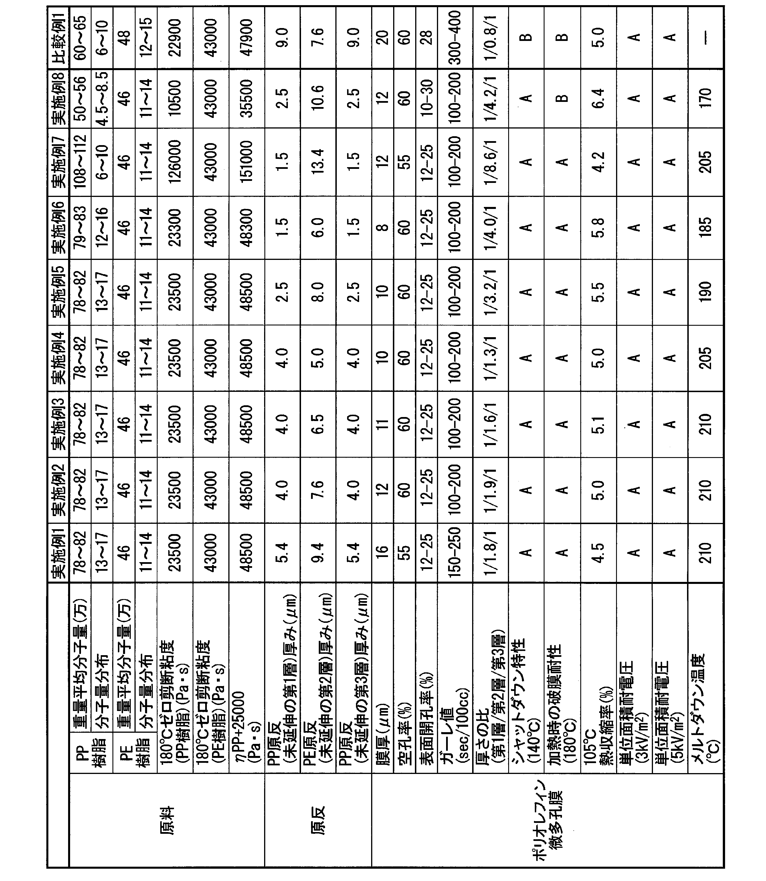
実施例1~8、比較例1において原料として使用したPP樹脂および実施例1~8、比較例1において原料として使用したPE樹脂の180℃条件によるゼロ剪断粘度を上記の方法により測定した。その結果を表1に示す。
表1に示すように、実施例1~5において使用したPP樹脂のゼロ剪断粘度は、23500Pa・sであった。また、実施例6において使用したPP樹脂のゼロ剪断粘度は、23300Pa・sであり、実施例7において使用したPP樹脂のゼロ剪断粘度は、126000Pa・sであり、実施例8において使用したPP樹脂のゼロ剪断粘度は、10500Pa・sであった。また、比較例1において使用したPP樹脂のゼロ剪断粘度は、22900Pa・sであった。
表1に示すように、実施例1~5において使用したPP樹脂のゼロ剪断粘度は、23500Pa・sであった。また、実施例6において使用したPP樹脂のゼロ剪断粘度は、23300Pa・sであり、実施例7において使用したPP樹脂のゼロ剪断粘度は、126000Pa・sであり、実施例8において使用したPP樹脂のゼロ剪断粘度は、10500Pa・sであった。また、比較例1において使用したPP樹脂のゼロ剪断粘度は、22900Pa・sであった。
また、表1に示すように、実施例1~8、比較例1において原料として使用したPE樹脂は、43000Pa・sであった。
また、PP樹脂の180℃でのゼロ剪断粘度ηPP(Pa・s)から、ηPP+25000(Pa・s)の値を算出した。その結果を表1に示す。
表1に示すように、実施例1~7、比較例1では、PE樹脂の180℃でのゼロ剪断粘度ηPE(Pa・s)は、ηPP(PP樹脂の180℃でのゼロ剪断粘度)+25000(Pa・s)以下であった。
これに対し、実施例8では、PE樹脂の180℃でのゼロ剪断粘度ηPE(Pa・s)は、ηPP(PP樹脂の180℃でのゼロ剪断粘度)+25000(Pa・s)超であった。
また、PP樹脂の180℃でのゼロ剪断粘度ηPP(Pa・s)から、ηPP+25000(Pa・s)の値を算出した。その結果を表1に示す。
表1に示すように、実施例1~7、比較例1では、PE樹脂の180℃でのゼロ剪断粘度ηPE(Pa・s)は、ηPP(PP樹脂の180℃でのゼロ剪断粘度)+25000(Pa・s)以下であった。
これに対し、実施例8では、PE樹脂の180℃でのゼロ剪断粘度ηPE(Pa・s)は、ηPP(PP樹脂の180℃でのゼロ剪断粘度)+25000(Pa・s)超であった。
表1に示すように、実施例1~8は、いずれもシャットダウン特性の評価が「A」であった。
これに対し、比較例1はシャットダウン特性の評価が「B」および加熱時の破膜耐性の評価が「B」であり、実施例1~8と比較して、安全性の劣るものであった。これは、比較例1では、実施例1~8と異なり、ポリオレフィン微多孔膜におけるPP樹脂からなる第1層の厚さおよび第3層の厚さが、PE樹脂からなる第2層の厚さよりも厚い。このため、比較例1では、溶融したPE樹脂によってPP樹脂の空隙を十分に閉塞できなかったものと推定される。
これに対し、比較例1はシャットダウン特性の評価が「B」および加熱時の破膜耐性の評価が「B」であり、実施例1~8と比較して、安全性の劣るものであった。これは、比較例1では、実施例1~8と異なり、ポリオレフィン微多孔膜におけるPP樹脂からなる第1層の厚さおよび第3層の厚さが、PE樹脂からなる第2層の厚さよりも厚い。このため、比較例1では、溶融したPE樹脂によってPP樹脂の空隙を十分に閉塞できなかったものと推定される。
さらに、実施例1~7は、シャットダウン特性の評価だけでなく、加熱時の破膜耐性の評価も「A」であり、メルトダウン温度が180℃以上であった。これは、実施例1~7では、PP樹脂の180℃でのゼロせん断粘度が高く、第2層を構成するPE樹脂の180℃でのゼロ剪断粘度ηPE(Pa・s)が、ηPP+25000(Pa・s)以下であるためであると推定される。より詳細には、シャットダウン時におけるPE樹脂からなる第2層の収縮および溶融の影響によって、PP樹脂からなる第1層および第3層が耐えられずに変形し、短時間で破膜する現象が抑制されることによるものであると推定される。
Claims (5)
- ポリプロピレン樹脂で構成された第1層と、
前記第1層の上に層設され、ポリエチレン樹脂で構成された第2層と、
前記第2層の上に更に層設され、ポリプロピレン樹脂で構成された第3層とからなる積層構造を有し、
前記第1層の厚さと前記第3層の厚さが、それぞれ前記第2層の厚さよりも薄く、
前記積層構造は、厚さが16μm以下、空孔率が40~70%、表面開孔率が10~30%であることを特徴とするポリオレフィン微多孔膜。 - 前記ポリエチレン樹脂の180℃でのゼロ剪断粘度ηPE(Pa・s)が、以下の式(I)を満たすことを特徴とする請求項1に記載のポリオレフィン微多孔膜。
ηPE≦ηPP+25000 (I)
(式(I)において、ηPPは、ポリプロピレン樹脂の180℃でのゼロ剪断粘度(Pa・s)を示す。) - 前記第1層および前記第3層の厚さを1としたとき、前記第2層の厚さが2以上であることを特徴とする請求項1または請求項2に記載のポリオレフィン微多孔膜。
- 10cm×100cmサイズの試験片に電圧をかけた短絡試験において、導通しない電圧を測定して得られた値である単位面積耐電圧が、3kV/m2以上であることを特徴とする請求項1~3のいずれか一項に記載のポリオレフィン微多孔膜。
- 請求項1~4のいずれか一項に記載のポリオレフィン微多孔膜が電極間に介在されていることを特徴とする蓄電デバイス。
Priority Applications (2)
| Application Number | Priority Date | Filing Date | Title |
|---|---|---|---|
| CN201980085582.9A CN113226732B (zh) | 2018-12-27 | 2019-12-26 | 聚烯烃微多孔膜及蓄电装置 |
| US17/418,152 US11837751B2 (en) | 2018-12-27 | 2019-12-26 | Polyolefin micro-porous film and power-storage device |
Applications Claiming Priority (2)
| Application Number | Priority Date | Filing Date | Title |
|---|---|---|---|
| JP2018-245963 | 2018-12-27 | ||
| JP2018245963A JP7275574B2 (ja) | 2018-12-27 | 2018-12-27 | ポリオレフィン微多孔膜及び蓄電デバイス |
Publications (1)
| Publication Number | Publication Date |
|---|---|
| WO2020138293A1 true WO2020138293A1 (ja) | 2020-07-02 |
Family
ID=71128733
Family Applications (1)
| Application Number | Title | Priority Date | Filing Date |
|---|---|---|---|
| PCT/JP2019/051134 Ceased WO2020138293A1 (ja) | 2018-12-27 | 2019-12-26 | ポリオレフィン微多孔膜及び蓄電デバイス |
Country Status (4)
| Country | Link |
|---|---|
| US (1) | US11837751B2 (ja) |
| JP (1) | JP7275574B2 (ja) |
| CN (1) | CN113226732B (ja) |
| WO (1) | WO2020138293A1 (ja) |
Families Citing this family (4)
| Publication number | Priority date | Publication date | Assignee | Title |
|---|---|---|---|---|
| CN113631362B (zh) * | 2019-03-27 | 2023-04-14 | 旭化成株式会社 | 蓄电装置用分隔件 |
| WO2024212052A1 (zh) * | 2023-04-10 | 2024-10-17 | 宁德时代新能源科技股份有限公司 | 隔离膜及其相关的二次电池和用电装置 |
| KR102985281B1 (ko) * | 2023-07-14 | 2026-07-03 | 셴젠 시니어 테크놀로지 매테리얼 씨오., 엘티디. | 리튬전지용 미세다공성 분리막 및 그 제조방법 |
| KR20260040057A (ko) * | 2023-08-04 | 2026-03-23 | 유비이 맥스엘 씨오., 엘티디. | 폴리올레핀 미세다공막, 그를 이용한 축전 디바이스용 세퍼레이터 필름, 및 축전 디바이스 |
Citations (2)
| Publication number | Priority date | Publication date | Assignee | Title |
|---|---|---|---|---|
| JP2016014107A (ja) * | 2014-07-02 | 2016-01-28 | 旭化成イーマテリアルズ株式会社 | 微多孔性フィルムの製造方法 |
| JP2017141428A (ja) * | 2016-02-09 | 2017-08-17 | 宇部興産株式会社 | ポリオレフィン微多孔膜、蓄電デバイス用セパレータフィルム、及び蓄電デバイス |
Family Cites Families (6)
| Publication number | Priority date | Publication date | Assignee | Title |
|---|---|---|---|---|
| JP3436055B2 (ja) * | 1997-03-18 | 2003-08-11 | 宇部興産株式会社 | 電池用セパレータ |
| JP5086736B2 (ja) | 2007-08-15 | 2012-11-28 | 三菱樹脂株式会社 | 積層多孔性フィルム、それを利用した電池用セパレータおよび電池 |
| US20120276367A1 (en) * | 2009-06-23 | 2012-11-01 | Pierre Carreau | Cast films, microporous membranes, and method of preparation thereof |
| JP2016060061A (ja) * | 2014-09-16 | 2016-04-25 | 旭化成イーマテリアルズ株式会社 | 積層微多孔フィルム及びその製造方法、並びに電池用セパレータ |
| KR102650164B1 (ko) * | 2014-11-26 | 2024-03-21 | 셀가드 엘엘씨 | 리튬 이온 재충전 가능한 배터리를 위한 개선된 미소공성 막 분리기 및 관련 방법 |
| JP2017170763A (ja) * | 2016-03-24 | 2017-09-28 | 東レフィルム加工株式会社 | 太陽電池モジュールバックシート用ポリエチレンフィルム |
-
2018
- 2018-12-27 JP JP2018245963A patent/JP7275574B2/ja active Active
-
2019
- 2019-12-26 CN CN201980085582.9A patent/CN113226732B/zh active Active
- 2019-12-26 WO PCT/JP2019/051134 patent/WO2020138293A1/ja not_active Ceased
- 2019-12-26 US US17/418,152 patent/US11837751B2/en active Active
Patent Citations (2)
| Publication number | Priority date | Publication date | Assignee | Title |
|---|---|---|---|---|
| JP2016014107A (ja) * | 2014-07-02 | 2016-01-28 | 旭化成イーマテリアルズ株式会社 | 微多孔性フィルムの製造方法 |
| JP2017141428A (ja) * | 2016-02-09 | 2017-08-17 | 宇部興産株式会社 | ポリオレフィン微多孔膜、蓄電デバイス用セパレータフィルム、及び蓄電デバイス |
Also Published As
| Publication number | Publication date |
|---|---|
| US11837751B2 (en) | 2023-12-05 |
| JP7275574B2 (ja) | 2023-05-18 |
| US20220102811A1 (en) | 2022-03-31 |
| CN113226732A (zh) | 2021-08-06 |
| CN113226732B (zh) | 2023-09-26 |
| JP2020104422A (ja) | 2020-07-09 |
Similar Documents
| Publication | Publication Date | Title |
|---|---|---|
| JP6696518B2 (ja) | ポリオレフィン微多孔膜 | |
| JP6094711B2 (ja) | ポリオレフィン微多孔膜、蓄電デバイス用セパレータフィルム、および蓄電デバイス | |
| JP6773044B2 (ja) | 多孔膜および蓄電デバイス | |
| CN110621731B (zh) | 聚烯烃微多孔膜、蓄电装置用分隔件及蓄电装置 | |
| JP5584371B2 (ja) | 非水電解質電池用セパレータ、非水電解質電池、および、非水電解質電池の製造方法 | |
| WO2016204274A1 (ja) | ポリオレフィン微多孔膜、蓄電デバイス用セパレータフィルム、および蓄電デバイス | |
| JP6187650B2 (ja) | 積層多孔質フィルム、蓄電デバイス用セパレータおよび蓄電デバイス | |
| CN113226732B (zh) | 聚烯烃微多孔膜及蓄电装置 | |
| CN120613545A (zh) | 改善的涂覆的分隔件、锂电池及相关方法 | |
| WO2017026482A1 (ja) | 積層多孔質フィルム、蓄電デバイス用セパレータおよび蓄電デバイス | |
| WO2017138512A1 (ja) | ポリオレフィン微多孔膜、蓄電デバイス用セパレータフィルム、及び蓄電デバイス | |
| JP5979299B1 (ja) | 積層多孔質フィルム、蓄電デバイス用セパレータおよび蓄電デバイス | |
| WO2025033202A1 (ja) | ポリオレフィン微多孔膜、それを用いた蓄電デバイス用セパレータフィルム、及び蓄電デバイス | |
| JP2024112773A (ja) | ポリオレフィン微多孔膜 |
Legal Events
| Date | Code | Title | Description |
|---|---|---|---|
| 121 | Ep: the epo has been informed by wipo that ep was designated in this application |
Ref document number: 19904231 Country of ref document: EP Kind code of ref document: A1 |
|
| NENP | Non-entry into the national phase |
Ref country code: DE |
|
| 122 | Ep: pct application non-entry in european phase |
Ref document number: 19904231 Country of ref document: EP Kind code of ref document: A1 |