WO2020138276A1 - 歯ブラシ - Google Patents
歯ブラシ Download PDFInfo
- Publication number
- WO2020138276A1 WO2020138276A1 PCT/JP2019/051095 JP2019051095W WO2020138276A1 WO 2020138276 A1 WO2020138276 A1 WO 2020138276A1 JP 2019051095 W JP2019051095 W JP 2019051095W WO 2020138276 A1 WO2020138276 A1 WO 2020138276A1
- Authority
- WO
- WIPO (PCT)
- Prior art keywords
- toothbrush
- neck
- covering
- stress relaxation
- neck portion
- Prior art date
- Legal status (The legal status is an assumption and is not a legal conclusion. Google has not performed a legal analysis and makes no representation as to the accuracy of the status listed.)
- Ceased
Links
Images







Classifications
-
- A—HUMAN NECESSITIES
- A46—BRUSHWARE
- A46B—BRUSHES
- A46B5/00—Brush bodies; Handles integral with brushware
-
- A—HUMAN NECESSITIES
- A46—BRUSHWARE
- A46B—BRUSHES
- A46B15/00—Other brushes; Brushes with additional arrangements
-
- A—HUMAN NECESSITIES
- A46—BRUSHWARE
- A46B—BRUSHES
- A46B17/00—Accessories for brushes
- A46B17/08—Other accessories, e.g. scrapers, rubber buffers for preventing damage to furniture
-
- A—HUMAN NECESSITIES
- A46—BRUSHWARE
- A46B—BRUSHES
- A46B5/00—Brush bodies; Handles integral with brushware
- A46B5/002—Brush bodies; Handles integral with brushware having articulations, joints or flexible portions
- A46B5/0054—Brush bodies; Handles integral with brushware having articulations, joints or flexible portions designed to allow relative positioning of the head to body
- A46B5/0062—Brush bodies; Handles integral with brushware having articulations, joints or flexible portions designed to allow relative positioning of the head to body being flexible or resilient during use
-
- A—HUMAN NECESSITIES
- A46—BRUSHWARE
- A46B—BRUSHES
- A46B5/00—Brush bodies; Handles integral with brushware
- A46B5/02—Brush bodies; Handles integral with brushware specially shaped for holding by the hand
- A46B5/023—Grips or handles specially adapted for children
-
- A—HUMAN NECESSITIES
- A46—BRUSHWARE
- A46B—BRUSHES
- A46B9/00—Arrangements of the bristles in the brush body
- A46B9/02—Position or arrangement of bristles in relation to surface of the brush body, e.g. inclined, in rows, in groups
- A46B9/04—Arranged like in or for toothbrushes
-
- A—HUMAN NECESSITIES
- A46—BRUSHWARE
- A46B—BRUSHES
- A46B2200/00—Brushes characterized by their functions, uses or applications
- A46B2200/10—For human or animal care
- A46B2200/1066—Toothbrush for cleaning the teeth or dentures
Definitions
- the present invention relates to toothbrushes.
- the present application claims priority based on Japanese Patent Application No. 2018-246854 filed in Japan on December 28, 2018, and the content thereof is incorporated herein.
- a "ring stick preventive toothbrush” that has a large ring-shaped throat sticking preventive plate fitted at the base of the neck of the toothbrush to prevent swallowing the toothbrush has already been sold. (For example, patent document 1).
- the throat thrust prevention plate is separately fitted to the base of the neck portion, so that it is necessary to form a base made of the primary side resin at the attachment site.
- stress concentration is likely to occur at the connecting portion between the base and the neck portion. In consideration of the fact that the neck length of the toothbrush for infants generally tends to be short, stress concentration during brushing is further increased.
- the toothbrush for infants which has the "throat-preventing plate” as a measure to prevent throat thrust and "covered with an elastomer” as a measure to prevent bites, has a major problem in terms of strength.
- One aspect of the present invention is made in view of the above problems of the prior art, and a high-strength toothbrush that prevents throat thrusting and bite scratches during use and is less likely to cause stress concentration during brushing.
- the purpose is to provide.
- a toothbrush according to one aspect of the present invention includes a toothbrush body and a throat prevention plate provided on the toothbrush body, and the toothbrush body extends from a head portion having a flocked surface and a rear end of the head portion.
- Made of a hard resin material having a neck portion, a handle portion located on the opposite side of the neck portion from the head portion, and a plate fitting base portion arranged between the neck portion and the handle portion. It is characterized by comprising a main body portion and a first coating portion made of a soft resin material for coating at least a part of the surface of the neck portion.
- a cutout portion is provided in a part of a circumferential direction of the plate fitting base portion, and the handle portion of the handle portion is provided through the first covering portion and the cutout portion.
- the second coating portion that covers at least a part may be continuous and integrated.
- the plate fitting base portion includes a fitting portion that fits into a plate side fitting receiving portion of the throat thrust prevention plate, and a through hole of the plate side fitting receiving portion. And a notch part that penetrates the fitting part and the insert part.
- a configuration in which an exposed portion that is not covered with the first covering portion is present adjacent to the plate fitting base portion at an end portion of the neck portion on the handle portion side May be
- the exposed portion has at least one stress relaxation portion on a boundary side with the first coating portion, and the exposed portion includes the first coating portion of the stress relaxation portion.
- the boundary may have a U-shape that is recessed toward the handle portion side.
- the first covering portion covers the entire circumferential direction of the neck portion in a region of at least 60% or more when the total length of the neck portion in the length direction is 100%. It may be configured to be.
- the stress relaxation portion may have a U-shaped depth within a range of 0.8 mm or more and 1.6 mm or less.
- the exposed portion has at least one stress relaxation portion on a boundary side with the first coating portion, and the exposed portion includes the first coating portion of the stress relaxation portion.
- the neck portion has a circular or elliptical cross-sectional shape, and the width is constant or wide in the length direction, and the first covering portion has the length in the length direction.
- the total length of the neck portion is 100%, at least 40% or more of the area may cover the entire circumferential direction of the neck portion.
- the Y-depth of the stress relaxation portion may be in the range of 1.0 mm or more and 3.5 mm or less.
- the stress relaxation portion may be provided on the same side as the flocked surface in the circumferential direction of the neck portion.
- a starting point of the stress relaxation portion on the neck portion side may be formed to have the same width as the neck portion.
- the minimum value of the width and the thickness of the neck portion may be 4.0 mm or more and 7.0 mm or less.
- the surface of the head part may be covered with the first covering part.
- FIG. 3 is a perspective view showing the overall configuration of the toothbrush of the first embodiment.
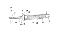
- FIG. 3 is a front view showing the configuration of the toothbrush body of the first embodiment.
- FIG. 3 is a side view showing the configuration of the toothbrush body of the first embodiment.
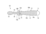
- FIG. 3 is a rear view showing the configuration of the toothbrush body of the first embodiment. The figure which expands and shows a part of neck part of 1st Embodiment.
- FIG. 3 is a front view showing the structure of the throat thrust prevention plate of the first embodiment.
- FIG. 3 is a perspective view showing the configuration of the throat thrust prevention plate of the first embodiment from the back side.
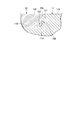
- FIG. 3 is a cross-sectional view showing a boundary portion between the main body portion and the covering portion of the first embodiment.
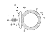
- the rear view which shows the structure of the toothbrush of 2nd Embodiment. The front view which shows the structure of the toothbrush main body of 2nd Embodiment.
- the rear view which shows the structure of the toothbrush main body of 2nd Embodiment. The elements on larger scale which show the structure of the neck part periphery of the toothbrush main body of 2nd Embodiment.
- FIG. 1 is a perspective view showing the overall configuration of the toothbrush 1 of the first embodiment.
- FIG. 2 is a front view showing the configuration of the toothbrush body 10 of the first embodiment.
- FIG. 3 is a side view showing the configuration of the toothbrush body of the first embodiment.
- FIG. 4 is a rear view showing the configuration of the toothbrush body 10 of the first embodiment.
- FIG. 5 is an enlarged view showing a part of the neck portion 14 of the first embodiment.
- the toothbrush 1 of the present embodiment shown in FIG. 1 is configured on the assumption that the toothbrush is used by a child aged between 6 months and 2 years old.
- the toothbrush 1 includes a toothbrush body 10 and a throat preventing plate 20 that is detachably attached to the toothbrush body 10.
- the toothbrush body 10 has an elongated shape as a whole, and includes a body portion 11 made of a hard resin material and a coating portion 12 made of a soft resin material for covering at least a part of the surface of the body portion 11. ing.
- the main body 11 includes a head main body 13A, a neck main body 14A, a plate fitting base 15 (FIG. 2), and a handle main body 16A, which are integrally formed in this order.
- the main body portion 11 can be manufactured by, for example, injection molding using a hard resin material.
- the constituent material of the main body 11 include polypropylene (PP), polyethylene terephthalate (PET), polybutylene terephthalate (PBT), polycyclohexylene dimethylene terephthalate (PCT), polyacetal (POM), polyethylene naphthalate (PEN), Examples thereof include polystyrene (PS), acrylonitrile-butadiene-styrene resin (ABS), cellulose propionate (CP), polyarylate, polycarbonate, and acrylonitrile-styrene copolymer resin (AS).
- PP polypropylene
- PET polyethylene terephthalate
- PBT polybutylene terephthalate
- PCT polycyclohexylene dimethylene terephthalate
- POM polyacetal
- PEN polyethylene naphthalate
- PS polystyrene
- ABS acrylonitrile-but
- resin materials it is preferable to use a material such as POM, PBT, or PEN in terms of high strength and easy thinning of the head portion 13.
- a material such as POM, PBT, or PEN in terms of high strength and easy thinning of the head portion 13.
- one kind of resin may be used alone, or two or more kinds of resins may be used in combination.
- the main body portion 11 has a first surface 11A that is not covered by the covering portion 12 and is exposed to the outside, a second surface 11B that is covered by the covering portion 12, the main body portion 11 and the covering portion. And a step portion 11F formed at a boundary portion with 12.
- the covering portion 12 includes a first covering portion 18 that covers at least a part of the surface of the neck body 14A and a second covering portion that covers at least a part or the entire surface of the handle body 16A. And the covering portion 17 of.
- the soft resin material of the covering portion 12 for example, a resin having a Shore A of 90 or less is preferable, and a resin having a Shore A of 30 to 80 is more preferable.
- a soft resin material include elastomer resins such as polyolefin-based elastomers, styrene-based elastomers, polyester-based elastomers, polyurethane-based thermoplastic elastomers, and silicon.
- a soft resin such as an elastomer is used, for example, polyolefin is preferable from the viewpoint of enhancing adhesiveness, and polypropylene is more preferable as the hard resin material in that case.
- FIG. 6 is a front view showing the structure of the throat thrust prevention plate 20 of the first embodiment.
- FIG. 7 is a perspective view showing the configuration of the throat thrust prevention plate 20 of the first embodiment from the back surface 20b side.
- FIG. 8 is a cross-sectional view showing a boundary portion between the main body portion and the covering portion of the first embodiment.
- the throat thrust prevention plate 20 has a disc shape as a whole, and an arbitrary design 22 is provided on the surface 20a side.
- the throat preventing plate 20 has a curved shape from the center to the peripheral edge, and the front surface 20a side shown in FIG. 6 is a convex surface and the back surface 20b side shown in FIG. 7 is a concave surface.
- the outer diameter of the throat thrust prevention plate 20 is preferably about 45 mm to 55 mm in terms of throat thrust prevention and operability.
- the material for the throat thrust prevention plate 20 may be made of the above hard material, but is preferably made of the soft resin material in terms of preventing throat thrust and bite scratches during use.
- a through hole 21 that is concentric with the central axis O is formed in the center of the throat thrust prevention plate 20.
- the diameter d1 of the through hole 21 is preferably about 12 mm to 15 mm.
- a plate-side fitting receiving portion 23 that is concentric with the central axis O is provided on the back surface 20b side of the throat thrust prevention plate 20.
- the plate-side fitting receiving portion 23 has a cylindrical shape.
- the diameter d2 of the plate side fitting receiving portion 23 is preferably about 16 mm to 20 mm. Further, the diameter d2 of the plate side fitting receiving portion 23 is larger than the diameter d1 of the through hole 21 (d1 ⁇ d2), and the ratio d1/d2 (ratio) is more preferably about 0.65 to 0.80. ..
- the throat thrust prevention plate 20 has an increased contact area with both the plate fitting portion 15A and the insertion portion 15B on the toothbrush body 10 side shown in FIG. It will be easy to fix it vertically and stably with respect to the axial direction. In particular, when the throat preventive plate 20 is made of a soft resin material, the above-mentioned effects are further exhibited.
- the overall length of the toothbrush main body 10 in the long axis direction is determined in consideration of operability by the infant, for example, about 100 mm to 140 mm. preferable.
- the head portion 13 is located on the tip side of the main body portion 11, has one side in the thickness direction, and a flocked surface 19.
- the head portion 13 is provided with a plurality of flocked portions 13a (FIG. 1), and a plurality of bristles having a predetermined length are bundled in a plurality of circular flocked holes 19a formed in the flocked surface 19 respectively.
- the tufted hair bundle 19b is planted.
- the material of the bristles constituting the hair bundle 19b is not particularly limited, and examples thereof include polyamides such as 6-12 nylon and 6-10 nylon, PET, PBT, polytrimethylene terephthalate (PTT), PEN, polybutylene na. Polyester such as phthalate (PBN), polyolefin such as PP, synthetic resin material such as olefin elastomer and styrene elastomer can be used. These resin materials may be used alone or in combination of two or more.
- the neck portion 14 is a portion extending from one end side of the head portion 13. Specifically, as shown in FIG. 2, in the plan view shape of the head portion 13, the end point of the curve forming the corner cut from the neck portion 14, that is, the boundary where the bending direction of the curve forming the corner cut changes. It is the length L1 from the position of P1 to the surface 15b of the insertion portion 15B.
- the neck portion 14 has a circular or elliptical cross-sectional shape, and its width is constant or widens in the length direction.
- the length of the neck portion 14 is determined in consideration of the size of the baby's oral cavity.
- the length L1 of the neck portion 14 is preferably about 14 mm to 21 mm, more preferably about 16 mm to 18 mm.
- the width and thickness dimensions (minimum diameter) of the thinnest portion of the neck portion 14 are preferably about 4.0 mm to 7.0 mm, and more preferably 5.0 mm to 7.0 mm. ..
- the width and thickness dimensions (maximum diameter) of the thickest part of the neck portion 14 are preferably about 5.0 mm to 9.0 mm, more preferably 5.0 mm to 8.0 mm. ..
- the dimensions of the width and the thickness of the neck portion 14 described above are the dimensions including the thickness of the first covering portion 18.
- the handle portion 16 is a portion that extends from one end side of the neck portion 14 (end portion on the side opposite to the end portion on the head portion 13 side) and that is gripped by the user.
- the handle portion 16 is defined from the end portion 11b of the main body portion 11 on the side of the head portion 13 opposite the end portion 11b to the base 15a of the plate fitting base portion 15.
- the width of the handle portion 16 is wider than the width of the neck portion 14.
- the length of the handle portion 16 is set according to the size of the hand of an infant, and is preferably about 65 mm to 80 mm, for example.
- the plate fitting base portion 15 is provided between the neck portion 14 and the handle portion 16, and, for example, in consideration of preventing throat thrusting of an infant, a length L2 along the major axis direction (from the surface 15b of the insertion portion 15B to the plate It is preferable that the distance from the fitting portion 15A to the base 15a) is in the range of 4 mm to 8 mm.
- the surface 15b of the insertion portion 15B is provided at a position 30 mm to 55 mm from the tip of the head portion 13.
- the plate fitting base portion 15 is formed in an annular shape around the axis of the toothbrush body 10.
- the plate fitting base portion 15 has a plate fitting portion 15A and an insertion portion 15B having different diameters, and is formed so as to concentrically expand outward in the minor axis direction with respect to the neck portion 14 and the handle portion 16. There is.
- the insertion portion 15B is a portion that is located on the neck portion 14 side of the plate fitting base portion 15 and is inserted into the through hole 21 of the throat thrust prevention plate 20 shown in FIGS. 6 and 7.
- the diameter of the insertion portion 15B is preferably substantially the same as the diameter of the through hole 21. In order to ensure waterproofness, it is desirable that the gap between them is small when the insertion portion 15B is inserted in the through hole 21.
- the surface 15b of the insertion portion 15B be substantially flush with the surface 20a of the throat preventing plate 20 as shown in FIG. 1 in a state where the insertion portion 15B is inserted into the through hole 21. ..
- the surface 15b of the insertion portion 15B be substantially flush with the surface 20a of the throat preventing plate 20 as shown in FIG. 1 in a state where the insertion portion 15B is inserted into the through hole 21. ..
- the plate fitting portion 15A is located on the handle portion 16 side of the plate fitting base portion 15.
- the plate fitting portion 15A has a larger diameter than the insertion portion 15B, and is a portion that fits into the plate-side fitting receiving portion 23 of the throat thrust prevention plate 20 shown in FIG.
- the diameter of the insertion portion 15B of the plate fitting base portion 15 corresponds to the diameter d1 of the through hole 21 of the throat thrust prevention plate 20 shown in FIG. 6, and is set within the range of 12 mm to 15 mm. Further, the thickness of the insertion portion 15B in the major axis direction is set so as to be within the range of 1.0 mm to 3.0 mm.
- the diameter of the plate fitting portion 15A corresponds to the diameter d2 of the plate-side fitting receiving portion 23 of the throat preventive plate 20 described above, and is set within the range of 16 mm to 20 mm. Further, the thickness of the plate fitting portion 15A in the long axis direction is set so as to be within the range of 4.0 mm to 6.0 mm.
- the plate fitting base portion 15 is provided with a cutout portion 31 that axially penetrates the above-described insertion portion 15B and plate fitting portion 15A in a part in the circumferential direction.
- the notch portion 31 is a portion that is notched toward the center of the plate fitting base portion 15 and is provided on the back surface (the surface opposite to the flocking surface 19) side of the toothbrush body 10. It is preferable that the cut-out depth of the notch portion 31 is such that the convex shape of the plate fitting base portion 15 is eliminated.
- the bottom surface of the cutout portion 31 is flush with the surfaces of the handle portion 16 and the neck portion 14 so as to smoothly connect the surface of the handle portion 16 and the surface of the neck portion 14.
- the width of the notch portion 31 is preferably in the range of 1.5 mm to 6.0 mm, more preferably 2.0 mm to 5.0 mm. Within the above range, the contact area between the throat thrust prevention plate 20 and the plate fitting base 15 can be secured, and the throat thrust prevention plate 20 can be more stably fixed to the toothbrush body. Further, the concentration of stress described later can be relieved.
- the depth of the cutout portion 31 corresponds to the flange width of the plate fitting portion 15A, and is within the range of 3.0 mm to 7.0 mm.
- the second covering portion 17 covers both side surfaces 16b, 16b from the back surface 16c of the handle portion 16 except for the surface on the rear end side of the handle portion 16. Further, it is provided so as to cover a part of the front surface 16a (edges on the side surfaces 16b, 16b side) so as to cover them continuously. As described above, since at least a part or the entire surface of the handle portion 16 is covered with the second cover portion 17, the fit of the hand when the user grips the handle portion 16 is improved, and the grip is improved. It is possible to prevent the fingers from slipping.
- At least the entire area of the surface of the head portion 13 other than the flocked surface 19 and the entire area of the surface of the neck portion 14 other than the proximal end side partial area of the first covering portion 18 are at least It is provided so as to cover a part of the surface in the circumferential direction.
- the entire circumferential direction of the neck portion 14 is covered with the first covering portion 18 in an area of at least 60% or more. .. It is more preferable that the first covering portion 18 can prevent the head portion 13 and the neck portion 14 from being bitten and scratched, and that the covering range is 80% or more.
- a region of about 60% or more of the total surface area of the neck portion 14 is covered with the first covering portion 18.
- the first covering portion 18 can prevent the head portion 13 and the neck portion 14 from being bitten. Further, it is more preferable that the coverage of the first coating portion 18 is 60% or more and 90% or less.
- the second covering portion 17 and the first covering portion 18 are continuous through the cutout portion 31 provided in the plate fitting base portion 15 and are integrally formed to form the covering portion 12.
- the thickness of the covering portion 12 is set to a minimum thickness that is not easily scratched while feeling softness when chewed.
- the thickness of the covering portion 12 is preferably 0.7 mm or more and 1.1 mm or less, more preferably 0.8 mm or more and 0.9 mm or less.
- the thickness of the covering portion 12 is preferably set within the above range.
- the height difference between the surfaces 11A and 12A at the boundary portion between the covering portion 12 and the main body portion 11 is small. Therefore, by setting the height of the step portion 11F of the main body portion 11 according to the thickness of the covering portion 12, the first surface 11A and the surface 12A of the covering portion 12 can be made flush with each other. ..
- the corner portion 11c on the first surface 11A side of the step portion 11F is a rounded corner having a radius of 0.2 mm to 0.5 mm and having the center O1 inside the main body portion 11.
- the corner portion 11d on the second surface 11B side of the step portion 11F is preferably a rounded corner having a radius of 0.2 mm to 0.5 mm and having the center O2 on the outside of the main body portion 11.
- each of the corner portions 11c and 11d at the boundary portion is 0.2 mm or more, the stress is easily dispersed even in a portion where the volume of the hard resin largely changes, and the strength is improved. If the radius of each corner 11c, 11d is 0.5 mm or less, the occurrence of burrs during molding can be suppressed.
- a finger contact portion 32 formed of a soft resin may be provided on a part of the front surface of the handle portion 16.
- the finger contact portion 32 is located closer to the neck portion 14 of the handle portion 16, and this portion connects (penetrates) the second covering portion 17 on the back surface side and the toothbrush body 10 as described above.
- it does not have to be within the range of the soft resin thickness. You may give arbitrary designs, characters, etc. to this finger contact part 32. Note that the finger contact portion 32 may have a certain thickness in order to make the design and characters stand out.
- an exposed portion 33 that is not covered by the first covering portion 18 exists adjacent to the plate fitting base portion 15 at the end portion of the neck portion 14 on the handle portion 16 side. To do. The entire surface of the neck portion 14 except the exposed portion 33 is covered with the first covering portion 18.
- the exposed portion 33 has at least one stress relaxation portion 34 on the boundary side with the first covering portion 18. As can be seen from the front view shown in FIG. 5, the stress relaxation portion 34 is provided on the same front side as the flocked surface 19 in the circumferential direction of the neck portion 14 and has the same width as the neck portion 14.
- the boundary between the stress relaxation portion 34 and the first covering portion 18 is a gentle U-shape that is open toward the head portion 13 side while being recessed toward the handle portion 16 side.
- the U-shaped depth T of the stress relaxation portion 34 is preferably in the range of 0.8 mm or more and 1.6 mm or less, and more preferably in the range of 1.0 mm or more and 1.4 mm or less.
- the U-shape of the stress relaxation section 34 preferably has a radius R of about 3.0 mm to 6.0 mm, more preferably about 4.0 mm to 5.0 mm. If the U-shape of the stress relaxation portion 34 is too sharp, the effect of stress dispersion will be weakened, so it is preferable to set it within the above range.
- the stress relaxation portion 34 is formed only on the front side of the neck portion 14, for example. As a result, the stress can be relaxed with respect to the boundary on the front side of the neck portion 14 and the plate fitting base portion 15 where the stress is likely to be concentrated and warped during use.
- the exposed portion 33 has one stress relaxation portion 34, but it may be provided on both sides of the neck portion 14, for example, and may have two or more stress relaxation portions 34.
- the position of the boundary line J at the position closest to the handle portion 16 among the boundaries between the first covering portion 18 and the exposed portion 33 is It is preferable that the plate fitting base 15 is located closer to the head 13 than the starting position.
- the starting position of the plate fitting base portion 15 in this embodiment is the position of the surface 15b of the insertion portion 15B when viewed from the front side of the toothbrush 1.
- the position of the boundary line is preferably 1 mm or more away from the start position of the plate fitting base portion 15.
- the toothbrush 1 of the present embodiment is manufactured by two-color molding using different materials on the primary side and the secondary side.
- the main body 11 serving as a base is manufactured by injection molding using a hard resin material.
- the covering portion 12 is manufactured by flowing a soft resin material into the mold from the handle portion 16 side of the main body portion 11 which is a primary molded product.
- the inflowing soft resin material covers a predetermined area on the surface of the handle portion 16, and then covers the neck portion 14 through the notch portion 31 provided on the back side of the plate fitting base portion 15, and then the flocking is continued.
- the covering portion 12 is formed on the surface of the main body portion 11. In this way, the toothbrush 1 of this embodiment is manufactured.
- the covering portion 12 is formed so as to cover the surface of the head portion 13 excluding the flocked surface 19, but the present invention is not limited to this, and the surface of the head portion 13 including the flocked surface 19 is covered.
- the covering portion 12 may be formed.
- cutout 31 only one cutout 31 is provided, but a plurality of cutouts 31 may be provided.
- the toothbrush 1 for infants needs to be configured so that it does not throat during use. Therefore, in the toothbrush 1 for infants, the throat preventing plate 20 is attached to the toothbrush main body 10 at a predetermined position, but the length of the neck portion 14 is shorter than that for an adult toothbrush, so that the brush for brushing is not required. The stress tends to concentrate on the base of the neck portion 14.
- toothbrush 1 of the present embodiment is devised to relieve stress during brushing.
- the toothbrush 1 of the present embodiment has a configuration in which the covering portion 12 that is generally provided only on the handle portion 16 is also provided on the neck portion 14 and the head portion 13. That is, by covering the surfaces of the head portion 13 and the neck portion 14 which are easily bitten by an infant during use, it is possible to prevent the bite from being scratched. Thereby, it can be used without damaging the inside of the oral cavity. In addition, it is possible to keep good hygiene. However, by having the coating structure, the volume of the hard resin material is reduced, and it is necessary to further secure the above-mentioned strength.
- the notch 31 is provided in the plate fitting base portion 15 of the main body portion 11 in consideration of the short length of the neck portion 14 for the toothbrush 1 for infants.
- the second covering portion 17 that covers the handle portion 16 and the first covering portion 18 that covers the head portion 13 and the neck portion 14 can be made into a continuous and integral structure.
- the boundary line between each of the coating portions 17 and 18 made of the soft resin material and the main body portion 11 made of the hard resin material does not close around the axis of the main body portion 11, so that the second coating portion 17 and the first The stress concentration at the boundary position can be relaxed more than in the configuration in which the covering portion 18 is separated.
- the stress during brushing can be easily dispersed in the long axis direction of the toothbrush 1. Therefore, it is preferable to provide the cutout portion 31 on the back surface side of the toothbrush 1 to which stress is easily applied during brushing.
- a step is not formed in the covering portion 18, and the tensile stress applied to the covering portion 17 can be dispersed.
- the U-shaped stress relaxation portion 34 in the exposed portion 33 of the neck portion 14, a boundary with the first covering portion 18 is formed in a U shape, and along the circumference of the neck portion 14 axis.
- the stress during brushing is more likely to be dispersed in the major axis direction than in the structure in which the boundary is formed in a circumferential shape, and high strength can be obtained.
- the U-shaped depth of the stress relaxation portion 34 is set to a dimension shallower than the above range, it is difficult to exert the stress relaxing effect, and if it is set to a dimension deeper than the above range, it is difficult to mold the main body portion 11. Therefore, it is preferable to define the dimensions within the above range.
- the stress relaxation portion 34 provided on the front side of the neck portion 14 faces the back surface of the base of the neck portion 14 where the load is most likely to be applied during brushing, so that when a shock or the like is applied, the neck portion of the main body portion 11 is affected. It is possible to prevent breakage in the portion 14.
- Table 1 shows the specifications and evaluation results of the toothbrushes of Examples 1 to 10, and Table 2 shows the specifications and evaluation results of the toothbrushes of Examples 11 to 14.
- the toothbrushes of Examples 1 to 14 have good operability in the oral cavity, are less likely to be bitten by scratches, sufficiently protect the oral cavity, and have sufficient strength of the neck portion 14 and the handle portion 16. Secured. Among these, the toothbrushes of Examples 1 to 10 were able to obtain each of the above effects on average.
- the toothbrush of Example 1 is well-balanced with respect to operability in the oral cavity, strength of the neck portion 14 and the handle portion 16, and protection of the oral cavity.
- the toothbrush of Example 2 When the toothbrush of Example 1 is used as a reference, the toothbrush of Example 2 has a smaller neck portion 14 (hard resin portion: core) than that of Example 1, and therefore is highly evaluated in terms of operability in the oral cavity. It was
- the neck portion 14 is thicker than that of Example 1, so that the strength of the neck portion 14 and the handle portion 16 is increased.
- the proportion of the elastomer resin in the elastomer resin and polypropylene of the neck portion 14 is slightly smaller than that in Example 1. Since the thickness of the neck portion 14 is the same as that of the first embodiment, the proportion of polypropylene in the neck portion 14 is slightly higher. Therefore, the strength of the neck portion 14 and the handle portion 16 is higher than that of the first embodiment.
- the ratio of the elastomer resin in the neck portion 14 was higher than that in Example 1, so that it was possible to sufficiently secure the protection in the oral cavity.
- the positions of the boundaries between the first covering portion 18 of the neck portion 14 and the insertion portion 15B of the plate fitting base portion 15 are partially aligned. That is, the bottom of the concave portion of the stress relaxation portion 34 of the exposed portion 33 of the neck portion 14 reaches the surface 15b of the insertion portion 15B of the plate fitting base portion 15, and the neck portion 14 is formed at a part of the neck portion 14 in the circumferential direction.
- the first covering portion 18 exists in the entire length direction of the. Even with such a configuration, an effect similar to that of the first embodiment could be obtained. From the viewpoint of strength of the neck portion 14 and the handle portion 16, it is desirable that the position of the boundary is located closer to the head portion 13 side than the plate fitting base portion 15 in the entire circumferential direction of the neck portion 14. I understood.
- the toothbrush of the seventh embodiment is configured without the stress relaxation section 34. Even with such a configuration, an effect similar to that of the first embodiment could be obtained. From the viewpoint of the strength of the neck portion 14 and the handle portion 16, it has been found that it is preferable to have the stress relaxation portion 34.
- the toothbrush of Example 8 has a structure in which the stress relaxation portion 34 has a shallow groove depth. Even with such a configuration, an effect similar to that of the first embodiment could be obtained. From the viewpoint of the strength of the neck portion 14 and the handle portion 16, it has been found that the groove depth of the stress relaxation portion 34 is preferably 0.8 mm or more.
- the toothbrush of Example 9 has a deep groove depth of the stress relaxation portion 34. Even with such a configuration, an effect similar to that of the first embodiment could be obtained. From the viewpoint of the strength of the neck portion 14 and the handle portion 16, it has been found that the groove depth of the stress relaxation portion 34 is preferably 1.6 mm or less.
- the toothbrush of the tenth embodiment has a configuration in which the stress relaxation portions 34 are provided not on the flocked surface 19 side but on both side surfaces of the neck portion 14, respectively. Even with such a configuration, an effect similar to that of the first embodiment could be obtained. From the viewpoint of the strength of the neck portion 14 and the handle portion 16, it has been found that it is desirable that the stress relaxation portion 34 is located on the side of the neck portion 14 on which the tuft surface 19 is implanted.
- the plate fitting base 15 was not provided with the notch 31, but the operability in the oral cavity was good, and the effect of protecting the oral cavity was sufficiently obtained.
- the neck portion 14 has a small thickness, so the operability in the oral cavity is very good.
- the toothbrush of Example 13 has a large effect of protecting the oral cavity because the proportion of the elastomer resin forming the neck portion 14 is large.
- the toothbrush of Example 14 has a high strength from the neck portion 14 to the handle portion 16 because the proportion of polypropylene constituting the neck portion 14 is large.
- the strength of the neck portion 14 not only the thickness of the neck portion 14 (thickness of polypropylene), but also the presence or absence of the cutout portion 31 of the plate fitting base portion 15, the first coating portion 18 in the neck portion 14 and the exposure
- the position of the boundary with the portion 33 (the position of the boundary between the elastomer resin and polypropylene), the position of the stress relaxation portion 34, and the like also contribute.
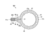
- FIG. 9A is a front view showing the configuration of the toothbrush of the second embodiment.
- FIG. 9B is a rear view showing the configuration of the toothbrush of the second embodiment.
- FIG. 10A is a front view showing the configuration of the toothbrush body of the second embodiment.
- FIG. 10B is a rear view showing the configuration of the toothbrush body of the second embodiment.
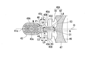
- FIG. 11 is a partially enlarged view showing the configuration around the neck portion of the toothbrush body of the second embodiment.
- FIG. 12 is a partially enlarged view showing the configuration around the neck portion of the toothbrush body of the second embodiment.
- the toothbrush 40 of the second embodiment is configured on the assumption that the toothbrush will be used by children up to about 8 months old.
- the toothbrush 40 includes a toothbrush main body 40A and a second throat thrust prevention plate 40B detachably attached to the toothbrush main body 40A.
- the toothbrush body 40A has a head portion 43, a neck portion 44, a plate fitting base portion 45, and a handle portion 46, which are integrally formed in this order.
- the handle portion 46 of the present embodiment is formed in a ring shape so that an infant can easily grasp it.
- the toothbrush body 40A includes a body portion 41 made of a hard resin material and a coating portion 42 made of a soft resin material for covering at least a part of the surface of the body portion 41.
- the main body portion 41 can be manufactured by injection molding using, for example, the same hard resin material as that used in the previous embodiment.
- the covering portion 42 has a first covering portion 48 that covers at least a part of the surface of the neck portion 44, and a second covering portion 47 that covers at least a part of or the entire surface of the handle portion 46.
- the soft resin material of the covering portion 42 the same material as in the first embodiment can be used.
- throat thrust prevention plate 40B The description of the throat thrust prevention plate 40B is omitted because it is the same as that of the first embodiment.
- the entire length of the toothbrush body 40A in the long axis direction is determined in consideration of operability by the infant. For example, it is preferably about 70 mm to 110 mm, more preferably about 80 mm to 100 mm.
- the head portion 43 is located on the tip side of the main body portion 41 and has flocked surfaces 49A and 49B on both sides in the thickness direction.
- a plurality of bristles 43a made of a soft resin material are provided on each of the flocked surfaces 49A and 49B.
- the material of the bristles 43a is not particularly limited, and examples thereof include polyamides such as 6-12 nylon and 6-10 nylon, PET, PBT, polytrimethylene terephthalate (PTT), PEN, polybutylene naphthalate (PBN), and the like.
- Polyolefin, polyolefin such as PP, olefin elastomer, styrene elastomer, synthetic resin material such as silicone can be used. These resin materials may be used alone or in combination of two or more. Since infants up to about 8 months old may bite the toothbrush during use, elastomers and silicones are preferable as the material for the bristles.
- the neck portion 44 is a portion extending from one end side of the head portion 43. Specifically, as shown in FIG. 11, in the plan view shape of the head portion 43, the end point of the curve forming the corner cut from the neck portion 44, that is, the boundary where the bending direction of the curve forming the corner cut changes.
- the length L3 from the position of P1 to the surface 45b of the insertion portion 45B is L3.
- the neck portion 44 has a circular or elliptical cross-sectional shape, and its width is constant or widens in the length direction.
- the length of the neck portion 44 is determined in consideration of the size of the baby's oral cavity. In the present embodiment, for example, as shown in FIG. 11, the length L3 of the neck portion 44 is preferably about 2 mm to 7 mm, more preferably about 3 mm to 6 mm.
- the range of the width and thickness dimensions (including the minimum diameter) in the thinnest portion of the neck portion 44 and the range of the width and thickness dimensions (including the maximum diameter) in the thickest portion of the neck portion 44 is the same as in the first embodiment.
- the dimensions of the width and the thickness of the neck portion 44 described above are the dimensions including the thickness of the first covering portion 48.
- the handle portion 46 of the present embodiment has a ring shape as shown in FIGS. 10A and 10B, and is provided on one end side of the neck portion 44 (end portion on the side opposite to the end portion on the head portion 43 side). ..
- the length L5 of the handle portion 46 shown in 10A is preferably about 60 mm to 70 mm, for example.
- the outer diameter D1 and the inner diameter D2 may be defined as shown in FIG. 10A.
- the difference between the outer diameter D1 and the inner diameter D2 of the handle portion 46 corresponds to the dimension of the width W of the handle portion 46 in a front view, and is set to a dimension that can be easily gripped by an infant.
- the width W of the handle portion 46 in a side view is formed to be wider than the width W2 of the neck portion 44.
- the plate fitting base portion 45 is provided between the neck portion 44 and the handle portion 46, and is formed in an annular shape around the central axis O of the toothbrush body 40A.
- the plate fitting base portion 45 includes a plate fitting portion 45A, an insertion portion 45B located on the head portion 43 side of the plate fitting portion 45A, and a reinforcing portion 45C located on the handle portion 46 side of the plate fitting portion 45A. , And are formed so as to concentrically expand in a direction orthogonal to the central axis O with respect to the neck portion 44 and the handle portion 46.
- the plate fitting portion 45A, the insertion portion 45B, and the reinforcing portion 45C have different diameters, and the plate fitting portion 45A has the largest diameter.
- the insertion portion 45B and the reinforcing portion 45C may have the same diameter or may have different diameters.
- the insertion portion 45B is a portion to which the throat thrusting prevention plate 20 is fitted, so it is necessary to match the diameter of the through hole 21, but the plate fitting base portion 45 is provided to secure the strength of the neck portion 44. Since it is a part, there is no particular regulation of the diameter.
- the diameter of the insertion portion 45B and the thickness of the insertion portion 45B in the long axis direction are the same as those in the first embodiment. Further, the diameter of the plate fitting portion 45A and the thickness of the plate fitting portion 45A in the long axis direction are the same as those in the first embodiment.
- the front surface (surface on the flocked surface 49A side) side shown in FIG. 10A and the back surface (surface on the flocked surface 49B side) shown in FIG. Notches 31, 31 are provided that axially penetrate the insertion portion 45B, the plate fitting portion 45A, and the reinforcing portion 45C shown.
- the notch portions 31, 31 have a depth at which the convex shape of the plate fitting base portion 45 disappears, as in the first embodiment. Also in the present embodiment, the respective bottom surfaces of the notch portions 31 and 31 are respectively connected to the surfaces of the handle portion 46 and the neck portion 44 so that the surface of the handle portion 46 and the surface of the neck portion 44 are connected smoothly. It is flush.
- the dimensions of the width and depth of the cutout portion 31 are the same as those in the first embodiment.
- the second covering portion 47 covers the handle portion 46 almost entirely as shown in FIGS. 9A and 9B.
- the opening 47a is provided in the second coating portion 47, and the design is such that a part of the main body portion 41 is exposed from the opening 47a.
- the presence or absence of the opening 47a, the shape, and the like can be appropriately changed.
- the first covering portion 48 covers at least a part of the neck portion 44 in the entire circumferential direction.
- the front end side of the neck portion 44 on the head portion 43 side is entirely covered with the first covering portion 48 around the axis of the central axis O (FIGS. 11 and 12 ).
- the first covering portion 48 in at least 40% or more of the area.
- the first coating portion 48 can prevent the head portion 43 and the neck portion 44 from being bitten and scratched, and that the coating range is 50% or more.
- the first covering portion 48 covers substantially the entire area including the flocked surfaces 49A and 49B of the head portion 43 and a part of the regions inside the cutout portions 31 and 31 provided on the front and back of the neck portion 44. Is provided.
- a region of about 60% or more of the total surface area of the neck portion 44 is covered with the first covering portion 48. It is more preferable that the first coating portion 48 can prevent the head portion 43 and the neck portion 44 from being bitten and scratched, and that the coating range is 65% or more.
- the second covering portion 47 and the first covering portion 48 are continuous through the pair of notches 31 and 31 provided in the plate fitting base portion 45, and are integrally configured with each other to cover the present embodiment. It constitutes the section 42.
- the thickness of the covering portion 42 is set to a minimum thickness that is not easily scratched while feeling softness when chewed.
- the thickness of the covering portion 12 is similar to that of the first embodiment.
- the surface of the plate fitting base portion 45 is not covered by either the first covering portion 48 or the second covering portion 47.
- the exposed portion 53 has a pair of stress relaxation portions 54, 54 on the boundary side with the first covering portion 48.
- the pair of stress relaxation portions 54, 54 are provided on the side surfaces on both sides of the toothbrush body 40A, respectively, and are at positions axially displaced from the positions of the cutout portions 31, 31.
- the boundaries between the stress relaxation portions 54 and 54 and the first coating portion 48 are, as shown in FIG. 11, when viewed from the front and the back of the toothbrush body 40A, respectively, through the notches 31 and 31, the handle portion 46. And has a Y shape protruding toward the head portion 43 side.
- the Y-shape of the stress relaxation portion 54 is such that the radius R1 when viewed from the front is about 0.5 mm to 3.5 mm at the tip of the stress relaxation portion 54 on the head portion 43 side. It is preferable to have. Further, as shown in FIG. 12, it is preferable that the radius R2 of the tip of the stress relaxation portion 54 when viewed from the side is, for example, about 1.0 mm to 2.5 mm.
- the Y-shape of the stress relaxation portion 54 may be formed by connecting a plurality of curves having different radii.
- the stress relief portions 54 and 54 are provided on the front surface and the back surface, respectively, to determine the front surface and the back surface. Even if a baby who has difficulty in using the brush uses either the front or back brush, it is possible to reduce the stress concentration on the neck portion 44 during use.
- the point M where the bifurcated curve changes to a straight line is the plate fitting. It is preferable to be located closer to the head portion 43 than the starting position of the base portion 45.
- the starting position of the plate fitting base portion 45 is the position of the surface 45b of the insertion portion 45B when viewed from the front side of the toothbrush 40.
- the depth T2 of the Y-shaped bifurcated portion of the stress relaxation portion 54 corresponds to the length from the end 41a, which is the starting point of the stress relaxation portion 54 on the head portion 43 side, to the point M.
- the Y-shaped depth T2 is, for example, preferably in the range of 1.0 mm or more and 3.5 mm or less, and more preferably in the range of 2.0 mm or more and 3.0 mm or less.
- the length L4 of the Y-shaped rear end of the stress relaxation portion 54 is at least 10 mm or more, and preferably in the range of 10 mm to 12 mm, for example.
- the length L4 is the length of the straight portion of the stress relaxation portion 54 on the handle portion 46 side, and corresponds to the distance from the point M to the boundary point N between the plate fitting base 45 and the handle portion 46. ..
- the distance L6 from the convergence point M of the Y-shaped bifurcated portion of the stress relaxation portion 54 to the surface 45b of the insertion portion 45B is preferably 1 mm or more. That is, it is preferable that the position of the convergence point M of the Y-shaped bifurcated portion of the stress relaxation portion 54 be separated from the start position of the plate fitting base portion 45 by 1 mm or more.
- width W3 of the starting point on the neck portion 44 side of the stress relaxation portion 54 shown in FIG. 12 is formed to be the same width W2 as the neck portion 44.
- the toothbrush 1 for infants has a structure that prevents throat thrusting during use, and the oral cavity of the infant is smaller than that of an infant, and all the deciduous teeth are not aligned, so the structure is gentle on the gums. There is a need to. It is also important to make the structure easy to hold even if the gripping force is weak.
- the length of the neck portion 44 is further shortened in accordance with the size of the baby's oral cavity as compared with a toothbrush for infants, and the handle shape is ring-shaped so that the baby can grasp the baby himself from any angle. I made it possible. Further, by providing the brush portions using the soft resin material on the front and back surfaces of the head portion 43, even a baby whose front and back surfaces are difficult to determine can be cleaned by simply biting the head portion 43 on both upper and lower teeth. Is possible. In addition, since the brush portion is made of a soft resin material, it is gentle on the gums and does not damage the inside of the oral cavity.
- the throat preventive plate 20 is attached to the toothbrush main body 40A at a predetermined position, but there is the plate fitting base 45 to which the throat thrust preventive plate 20 is attached.
- the part is strong and difficult to bend.
- the length of the neck portion 44 is extremely shorter than that of an adult toothbrush, stress during brushing tends to concentrate on the root of the neck portion 44.
- the notch portion 31 and the stress relaxation portion 54 are provided on both the front and back surfaces of the neck portion 44 in accordance with the front and back brush portions of the head portion 43 so that the stress during brushing can be relaxed. ..
- the plate fitting base portion 45 has a three-stage structure, and the reinforcing portion 45C is further provided at the base of the handle portion 46 side, so that the strength around the neck portion can be improved.
- Table 3 shows the specifications and evaluation results of the toothbrushes of Examples 1 to 9.
- the toothbrushes of Examples 1 to 8 have good operability in the oral cavity, are less likely to be bitten by scratches, sufficiently protect the oral cavity, and have sufficient strength of the neck portion 44 and the handle portion 46. Secured. Among these, particularly, the toothbrush of Example 1 was highly evaluated in each item.
- the toothbrush of Example 1 is highly evaluated and balanced with respect to operability in the oral cavity, strength of the neck portion 44 and the handle portion 46, and protection of the oral cavity.
- the toothbrush of Example 2 was evaluated in the same manner as in Example 1 in terms of oral operability and oral cavity protection. As for the strength of the neck portion 44, it has been found that the notch portion 31 is more preferable.
- the boundary position between the first covering portion 48 of the neck portion 44 and the insertion portion 45B of the plate fitting base portion 45 is partially matched, and the stress relaxation portion 54 is not provided. Is. Even with such a configuration, the same evaluation as in Example 1 was obtained for the oral operability and oral protection. As for the strength of the neck portion 44, it has been found that the notch portion 31 is more preferable.
- the toothbrush of the fourth embodiment does not have the stress relaxation portion 54. Even with such a configuration, the same evaluation as in Example 1 was obtained for the oral operability and oral protection. Further, it has been found that the strength of the neck portion 44 is preferably the one having the stress relaxation portion 54.
- the toothbrush of Example 5 has a Y-shaped bifurcated portion with a short length of 1.0 mm. Even with such a configuration, the same evaluation as in Example 1 was obtained for the oral operability and oral protection.
- the toothbrush of Example 6 has a long Y-shaped bifurcated portion of 3.9 mm. In the case of this configuration, the same evaluation as in Example 1 was obtained for the oral operability and oral protection, and a higher evaluation was obtained for the strength of the neck portion 44 than in Example 1. From Examples 5 and 6, it was found that in order to increase the strength of the neck portion 44, it is preferable that the Y-shaped bifurcated portion has a long length.
- the toothbrush of Example 7 has a configuration in which the thickness of the neck portion main body made of the primary resin is as thin as 4 mm in the neck portion 44, and therefore the oral operability and the oral cavity protection are evaluated. high. Since the thickness of the neck portion 44 (neck portion main body) of the toothbrush of Example 8 was as thick as 7 mm, the strength of the neck portion 44 was highly evaluated. From Examples 7 and 8, there is a trade-off relationship between the strength of the neck portion 44 and the intraoral operability and intraoral protection, and it is desirable to set the thickness of the neck portion 44 from the balance of both. Do you get it.
- the toothbrush of the ninth embodiment has a configuration in which the length of the first covering portion 48 is 30% of the total length of the neck portion 44.
- the same evaluation as in Example 1 was obtained for the intraoral operability, but the strength of the neck portion 44 and the oral protection were considerably lower than those in Example 1. Therefore, regarding the strength of the neck portion 44 and the protection of the oral cavity, it is desirable that the length of the first covering portion 48 with respect to the entire length of the neck portion 44 is 40% or more.
- the thinner the neck portion 44 the better the operability in the oral cavity, and when the thickness of the first covering portion 48 is 0.8 mm, the inside of the oral cavity is sufficiently Can be protected.
- the strength of the neck portion 44 not only the thickness of the neck portion 44 (thickness of polypropylene), but also the presence or absence of the cutout portion 31 of the plate fitting base 45, the position of the boundary between the elastomer resin and the polypropylene in the neck portion 44
- the position of the stress relaxation portion 54, the length of the Y-shaped bifurcated portion, and the like also contribute.
- the toothbrush body and the throat thrust prevention plate are separate members, and the throat thrust prevention plate is detachably attached to the toothbrush body.
- the toothbrush body and the throat thrust prevention plate may be integrated.
- the plate fitting base portion 15 of the toothbrush main body 10 has a two-stage configuration (plate fitting portion 15A, insertion portion 15B), but only one stage (plate fitting portion 15A or insertion portion 15B). Only), or the configuration of three or more stages as in the second embodiment. In this case, it is preferable to define the diameter and the like at the most expanded base portion.
- the configuration of the plate fitting base portion 45 is not limited to the above-described configuration, and may be, for example, one stage or two stages.
- the shape of the stress relaxation portion is not limited to the shape shown in each of the above-described embodiments, and for example, a U-shaped stress relaxation portion and a Y-shaped stress relaxation portion may be combined.
Landscapes
- Brushes (AREA)
Abstract
本発明の歯ブラシ(1)は、歯ブラシ本体(10)と、前記歯ブラシ本体(10)に設けられる喉突き防止プレート(20)と、を備え、前記歯ブラシ本体(10)は、植毛面(19)を有するヘッド部(13)と、前記ヘッド部(13)の後端から延びるネック部(14)と、前記ネック部の前記ヘッド部(13)とは反対側に位置するハンドル部(16)と、前記ネック部(14)と前記ハンドル部(16)との間に配置されたプレート嵌合土台部と、を有する硬質樹脂材料からなる本体部(11)と、前記ネック部(14)の少なくとも一部の表面を被覆する軟質樹脂材料からなる第1の被覆部と、を有して構成されている。
Description
本発明は、歯ブラシに関する。
本願は、2018年12月28日に、日本に出願された特願2018-246854号に基づき優先権を主張し、その内容をここに援用する。
本願は、2018年12月28日に、日本に出願された特願2018-246854号に基づき優先権を主張し、その内容をここに援用する。
小児期からのプラークコントロールの習慣化は、生涯にわたって口腔の健康に大きく左右するため、適切なブラッシング技術を習得させる必要がある。しかし乳幼児は、歯みがきに対して不慣れであるため、歯ブラシの誤飲や転倒による喉突きに注意しなければならない。また、ブラッシング中に歯ブラシを噛んでしまうことで、歯ブラシの表面に凹凸やバリが発生し、口腔内が傷ついてしまうことが懸念される。
歯ブラシによる喉突き防止策としては、歯ブラシのネック部の根元に大きなリング状の喉突き防止プレートを嵌合させることで、歯ブラシを飲み込めないようにした「喉突き防止歯ブラシ」が既に販売されている(例えば、特許文献1)。
一方、歯ブラシに対する噛み傷の防止策としては、ポリプロピレンなどの硬質樹脂材料(1次側樹脂)からなるヘッド部からネック部にかけて、エラストマー等の軟質樹脂材料(2次側樹脂)で被覆することで、表面に傷がつかないようにする手法がある。本施策は、仮に、1次側樹脂が破断してもその表面が2次側樹脂で覆われているため、鋭利な破断面が露出しにくいという利点もあり、一般的によく用いられる(例えば、特許文献2)。
しかしながら、1次側樹脂を2次側樹脂で被覆することによる上記施策を、歯ブラシのネック部に適用した場合、いわゆる二重芯構造となるため、1次側樹脂の体積が稼ぎにくくなり、強度の面で課題が生じる。特に、口腔が小さい乳幼児用の歯ブラシでは、歯ブラシのヘッド部の大きさやネック部の径に制約があるため、1次側樹脂の量を増やす以外の施策が必要となる。
また、上述した二重芯構造を「喉突き防止歯ブラシ」に適用すると、強度面での技術的難易度は更に高くなる。「喉突き防止歯ブラシ」では、ネック部の根元に喉突き防止プレートを別途嵌合させることから、その取り付け部位に、1次側樹脂による土台を形成する必要がある。ところが、歯ブラシの使用時に、土台とネック部との連結部位で応力集中が起こりやすくなってしまう。乳幼児用の歯ブラシは、ネック部の長さが一般的に短い傾向にあることを考慮すると、ブラッシング時の応力集中は更に増すこととなる。
このように、喉突き防止策として「喉突き防止プレート」を有するとともに、噛み傷防止策として「エラストマーによる被覆」を施した乳幼児用の歯ブラシにおいては、強度面において大きな課題がある。
本発明の一つの態様は、上記従来技術の問題点に鑑み成されたものであって、使用時における喉突きや噛み傷を防ぐとともに、ブラッシング時の応力集中を生じにくくした強度の高い歯ブラシを提供することを目的とする。
本発明の一つの態様の歯ブラシは、歯ブラシ本体と、前記歯ブラシ本体に設けられる喉突き防止プレートと、を備え、前記歯ブラシ本体は、植毛面を有するヘッド部と、前記ヘッド部の後端から延びるネック部と、前記ネック部の前記ヘッド部とは反対側に位置するハンドル部と、前記ネック部と前記ハンドル部との間に配置されたプレート嵌合土台部と、を有する硬質樹脂材料からなる本体部と、前記ネック部の少なくとも一部の表面を被覆する軟質樹脂材料からなる第1の被覆部と、を有して構成されていることを特徴とする。
本発明の一つの態様の歯ブラシにおいて、前記プレート嵌合土台部の周方向の一部に切り欠き部が設けられており、前記第1の被覆部と、前記切り欠き部を通じて、前記ハンドル部の少なくとも一部を被覆する第2の被覆部と、が連続し、一体となっている構成としてもよい。
本発明の一つの態様の歯ブラシにおいて、前記プレート嵌合土台部は、前記喉突き防止プレートのプレート側嵌合受け部に嵌合する嵌合部と、前記プレート側嵌合受け部の貫通孔内に挿入される挿入部と、を有し、前記切り欠き部は、前記嵌合部および前記挿入部を貫通する構成としてもよい。
本発明の一つの態様の歯ブラシにおいて、前記ネック部の前記ハンドル部側の端部には、前記プレート嵌合土台部に隣接して、前記第1の被覆部で被覆されない露出部が存在する構成としてもよい。
本発明の一つの態様の歯ブラシにおいて、前記露出部は、前記第1の被覆部との境界側に少なくとも一つの応力緩和部を有しており、前記応力緩和部の前記第1の被覆部との境界が前記ハンドル部側に凹むU字形状をなす構成としてもよい。
本発明の一つの態様の歯ブラシにおいて、前記第1の被覆部は、長さ方向における前記ネック部の全長を100%としたときに、少なくとも60%以上の領域においてネック部の周方向全体を被覆している構成としてもよい。
本発明の一つの態様の歯ブラシにおいて、前記応力緩和部のU字深さは、0.8mm以上、1.6mm以下の範囲内である構成としてもよい。
本発明の一つの態様の歯ブラシにおいて、前記露出部は、前記第1の被覆部との境界側に少なくとも一つの応力緩和部を有しており、前記応力緩和部の前記第1の被覆部との境界が前記ハンドル部側に凹むY字形状をなし、前記切り欠き部を通じて、前記第1の被覆部と、前記ハンドル部の少なくとも一部を被覆する第2の被覆部と、が連続し、互いに一体となっている構成としてもよい。
本発明の一つの態様によれば、前記ネック部は、円形または楕円形の断面形状であり、幅が長さ方向に一定あるいは拡がっており、前記第1の被覆部は、長さ方向における前記ネック部の全長を100%としたときに、少なくとも40%以上の領域においてネック部の周方向全体を被覆している構成としてもよい。
本発明の一つの態様の歯ブラシにおいて、前記応力緩和部のY字深さは、1.0mm以上、3.5mm以下の範囲内である構成としてもよい。
本発明の一つの態様の歯ブラシにおいて、前記応力緩和部は、前記ネック部の周方向のうち前記植毛面と同じ側に設けられている構成としてもよい。
本発明の一つの態様の歯ブラシにおいて、前記応力緩和部の前記ネック部側の始点は、前記ネック部と同じ幅で形成されている構成としてもよい。
本発明の一つの態様によれば、前記ネック部の幅および厚さの最小値が、4.0mm以上、7.0mm以下である構成としてもよい。
本発明の一つの態様によれば、前記ヘッド部の表面が前記第1の被覆部によって覆われている構成としてもよい。
本発明によれば、使用時における喉突きや噛み傷を防ぐとともに、ブラッシング時の応力集中を生じにくくした強度の高い歯ブラシを提供することができる。
以下、本発明に係る各実施形態の歯ブラシの構成について説明する。
なお、以下の各図面においては、各構成要素を見やすくするため、構成要素によって寸法の縮尺を異ならせて示すことがある。
なお、以下の各図面においては、各構成要素を見やすくするため、構成要素によって寸法の縮尺を異ならせて示すことがある。
[第1実施形態]
図1は、第1実施形態の歯ブラシ1の全体の構成を示す斜視図である。図2は、第1実施形態の歯ブラシ本体10の構成を示す正面図である。図3は、第1実施形態の歯ブラシ本体の構成を示す側面図である。図4は、第1実施形態の歯ブラシ本体10の構成を示す背面図である。図5は、第1実施形態のネック部14の一部を拡大して示す図である。
図1は、第1実施形態の歯ブラシ1の全体の構成を示す斜視図である。図2は、第1実施形態の歯ブラシ本体10の構成を示す正面図である。図3は、第1実施形態の歯ブラシ本体の構成を示す側面図である。図4は、第1実施形態の歯ブラシ本体10の構成を示す背面図である。図5は、第1実施形態のネック部14の一部を拡大して示す図である。
図1に示す本実施形態の歯ブラシ1は、生後6ヶ月から2歳くらいの子供が使用する歯ブラシを想定して構成されている。歯ブラシ1は、歯ブラシ本体10と、歯ブラシ本体10に対して着脱可能に装着される喉突き防止プレート20と、を備える。
歯ブラシ本体10は、全体として長尺形状をなし、硬質樹脂材料からなる本体部11と、本体部11の少なくとも一部の表面を覆う軟質樹脂材料からなる被覆部12と、を有して構成されている。
本体部11は、ヘッド部本体13A、ネック部本体14A、プレート嵌合土台部15(図2)およびハンドル部本体16Aにより構成され、この順に一体に形成されている。
本体部11は、ヘッド部本体13A、ネック部本体14A、プレート嵌合土台部15(図2)およびハンドル部本体16Aにより構成され、この順に一体に形成されている。
本体部11は、例えば、硬質樹脂材料を用いた射出成形により作製することができる。
本体部11の構成材料として、例えば、ポリプロピレン(PP)、ポリエチレンテレフタレート(PET)、ポリブチレンテレフタレート(PBT)、ポリシクロへキシレンジメチレンテレフタレート(PCT)、ポリアセタール(POM)、ポリエチレンナフタレート(PEN)、ポリスチレン(PS)、アクリロニトリル・ブタジエン・スチレン樹脂(ABS)、セルロースプロピオネート(CP)、ポリアリレート、ポリカーボネート、アクリロニトリル・スチレン共重合樹脂(AS)などが挙げられる。これらの樹脂材料のうち、強度が高く、ヘッド部13を薄肉化しやすい点では、POM、PBT、PENなどの材料を用いることが好ましい。なお、上記の樹脂は、1種の樹脂を単独で使用してもよいし、2種以上の樹脂を併用してもよい。
本体部11の構成材料として、例えば、ポリプロピレン(PP)、ポリエチレンテレフタレート(PET)、ポリブチレンテレフタレート(PBT)、ポリシクロへキシレンジメチレンテレフタレート(PCT)、ポリアセタール(POM)、ポリエチレンナフタレート(PEN)、ポリスチレン(PS)、アクリロニトリル・ブタジエン・スチレン樹脂(ABS)、セルロースプロピオネート(CP)、ポリアリレート、ポリカーボネート、アクリロニトリル・スチレン共重合樹脂(AS)などが挙げられる。これらの樹脂材料のうち、強度が高く、ヘッド部13を薄肉化しやすい点では、POM、PBT、PENなどの材料を用いることが好ましい。なお、上記の樹脂は、1種の樹脂を単独で使用してもよいし、2種以上の樹脂を併用してもよい。
本体部11は、図8に示すように、被覆部12によって被覆されず外部に露出した第1の表面11Aと、被覆部12によって被覆される第2の表面11Bと、本体部11と被覆部12との境界部分に形成される段差部11Fと、を有する。
図2に示すように、被覆部12は、ネック部本体14Aの少なくとも一部の表面を被覆する第1の被覆部18と、ハンドル部本体16Aの少なくとも一部または全体の表面を被覆する第2の被覆部17と、からなる。
被覆部12の軟質樹脂材料としては、例えば、ショアA90以下の樹脂であることが好ましく、ショアA30~80の樹脂であることがより好ましい。このような軟質樹脂材料としては、例えば、ポリオレフィン系エラストマー、スチレン系エラストマー、ポリエステル系エラストマー、ポリウレタン系熱可塑性エラストマー等のエラストマー樹脂、シリコン等が挙げられる。エラストマーなどの柔軟な樹脂を用いる場合には、接着性を高められる観点から、例えば、ポリオレフィンが好ましく、その場合の硬質樹脂材料はポリプロピレンがより好ましい。
(喉突き防止プレート)
先ず、喉突き防止プレート20の構成について詳述する。
図6は、第1実施形態の喉突き防止プレート20の構成を示す正面図である。図7は、第1実施形態の喉突き防止プレート20の構成を裏面20b側から示す斜視図である。図8は、第1実施形態の本体部と被覆部との境界部分を示す断面図である。
先ず、喉突き防止プレート20の構成について詳述する。
図6は、第1実施形態の喉突き防止プレート20の構成を示す正面図である。図7は、第1実施形態の喉突き防止プレート20の構成を裏面20b側から示す斜視図である。図8は、第1実施形態の本体部と被覆部との境界部分を示す断面図である。
図6に示すように、喉突き防止プレート20は、全体として円板形状とされ、表面20a側には任意のデザイン22が施されている。喉突き防止プレート20は、中央から周縁に行くに従って湾曲した形状となっており、図6に示す表面20a側が凸面、図7に示す裏面20b側が凹面となっている。喉突き防止プレート20の外周径は、45mm~55mm程度であることが、喉突き防止、および操作性の点で好ましい。喉突き防止プレート20の材質は上記硬質材料で構成されても良いが、上記軟質樹脂材料で構成されれば、使用時における喉突きや噛み傷を防ぐ点で、より好ましい。
喉突き防止プレート20の中央には、中心軸Oと同心をなす貫通孔21が形成されている。貫通孔21の直径d1は、12mm~15mm程度であることが好ましい。
喉突き防止プレート20の裏面20b側には、中心軸Oと同心をなすプレート側嵌合受け部23が設けられている。プレート側嵌合受け部23は、円筒形状をなす。プレート側嵌合受け部23の直径d2は、16mm~20mm程度であることが好ましい。また、プレート側嵌合受け部23の直径d2は、貫通孔21の直径d1よりも大きく(d1<d2)、d1/d2(比率)は0.65~0.80程度であることがより好ましい。
上記範囲であれば、喉突き防止プレート20が、図2に示した歯ブラシ本体10側のプレート嵌合部15Aと挿入部15Bの双方との接触面積が増加し、喉突き防止プレート20を歯ブラシ長軸方向に対して安定して垂直に固定しやすくなる。特に、喉突き防止プレート20が軟質樹脂材料である場合は、上述したような効果がより発揮される。
(歯ブラシ本体)
次に、歯ブラシ本体10の構成について詳述する。
本実施形態では、歯ブラシ1の使用対象者が乳幼児であることから、歯ブラシ本体10の長軸方向全体の長さは、乳幼児による操作性等を勘案して決定され、例えば、100mm~140mm程度が好ましい。
次に、歯ブラシ本体10の構成について詳述する。
本実施形態では、歯ブラシ1の使用対象者が乳幼児であることから、歯ブラシ本体10の長軸方向全体の長さは、乳幼児による操作性等を勘案して決定され、例えば、100mm~140mm程度が好ましい。
ヘッド部13は、図2~図4に示すように、本体部11の先端側に位置し、厚さ方向の一方側、植毛面19を有している。ヘッド部13には、複数の植毛部13a(図1)が設けられており、植毛面19に形成された複数の円形の植毛穴19aのそれぞれに、所定の長さの複数の用毛が束ねられた毛束19bが植設されている。
毛束19bを構成する用毛の材質としては、特に限定されず、例えば、6-12ナイロン、6-10ナイロン等のポリアミド、PET、PBT、ポリトリメチレンテレフタレート(PTT)、PEN、ポリブチレンナフタレート(PBN)等のポリエステル、PP等のポリオレフィン、オレフィン系エラストマー、スチレン系エラストマー等の合成樹脂材料を用いることができる。これらの樹脂材料は、1種単独で用いられてもよいし、2種以上が組み合わされて用いられてもよい。
ネック部14は、ヘッド部13の一端側から延びる部分である。
具体的には、図2に示すように、ヘッド部13の平面視形状における、ネック部14よりの隅切を形成する曲線の終点、即ち、隅切を形成する曲線の曲がり方向が変化する境界P1の位置から、挿入部15Bの表面15bまでの長さL1である。ネック部14は、円形または楕円形の断面形状であり、その幅は長さ方向に一定あるいは拡がっている。
具体的には、図2に示すように、ヘッド部13の平面視形状における、ネック部14よりの隅切を形成する曲線の終点、即ち、隅切を形成する曲線の曲がり方向が変化する境界P1の位置から、挿入部15Bの表面15bまでの長さL1である。ネック部14は、円形または楕円形の断面形状であり、その幅は長さ方向に一定あるいは拡がっている。
ネック部14の長さは、乳幼児の口腔内のサイズを考慮して決定される。本実施形態では、例えば、ネック部14の長さL1が、14mm~21mm程度であることが好ましく、16mm~18mm程度であることがより好ましい。
また、ネック部14のうち最も細い部分における幅および厚さの寸法(最小径)は、4.0mm~7.0mm程度であることが好ましく、5.0mm~7.0mmの範囲内がより好ましい。また、ネック部14のうち最も太い部分における幅および厚さの寸法(最大径)は、5.0mm~9.0mm程度であることが好ましく、5.0mm~8.0mmの範囲内がより好ましい。なお、上述したネック部14の幅および厚さの寸法は、第1の被覆部18の厚さを含んだ寸法である。
ハンドル部16は、ネック部14の一端側(ヘッド部13側の端部とは反対側の端部)から延びる部分であって、使用者が把持する部分である。本実施形態では、本体部11のヘッド部13側の端部11aとは反対側の端部11bから、プレート嵌合土台部15の付け根15aまでをハンドル部16と定義する。ハンドル部16の幅は、ネック部14の幅よりも広い幅で形成されている。また、ハンドル部16の長さは、乳幼児の手のサイズに合わせて設定され、例えば、65mm~80mm程度が好ましい。
プレート嵌合土台部15は、ネック部14とハンドル部16との間に設けられ、例えば、乳幼児の喉突き防止を考慮し、長軸方向に沿う長さL2(挿入部15Bの表面15bからプレート嵌合部15Aの付け根15aまでの距離)が、4mm~8mmの範囲内であることが好ましい。
更に、挿入部15Bの表面15bは、ヘッド部13の先端から30mm~55mmの位置に設けられることが、より好ましい。プレート嵌合土台部15は、歯ブラシ本体10の軸周りに円環状に形成されている。プレート嵌合土台部15は、互いに径の異なるプレート嵌合部15Aと挿入部15Bとを有し、ネック部14およびハンドル部16よりも短軸方向外側へ、同心円状に拡がるように形成されている。
挿入部15Bは、プレート嵌合土台部15のうちネック部14側に位置し、図6および図7に示す喉突き防止プレート20の貫通孔21に挿入される部分である。挿入部15Bの直径は、貫通孔21の直径と略同じであることが好ましい。防水性を確保するためにも、挿入部15Bが貫通孔21に挿入された状態で相互間の隙間が小さいことが望ましい。
また、挿入部15Bが貫通孔21に挿入された状態で、図1に示すように挿入部15Bの表面15bが、喉突き防止プレート20の表面20aと略面一の高さになることが好ましい。喉突き防止プレート20の表面20aと、挿入部15Bの表面15bとの段差をなくすことで、水分が溜まりにくくなり、衛生的に使用することができる。
図2に示すように、プレート嵌合部15Aは、プレート嵌合土台部15のうちハンドル部16側に位置する。プレート嵌合部15Aは、挿入部15Bよりも径が大きく、図7に示す喉突き防止プレート20のプレート側嵌合受け部23に嵌合する部分である。
プレート嵌合土台部15のうち、挿入部15Bの直径は、図6に示す喉突き防止プレート20の貫通孔21の直径d1に対応しており、12mm~15mmの範囲内で設定されている。また、長軸方向における挿入部15Bの厚さは、1.0mm~3.0mmの範囲内に収まるように設定されている。
プレート嵌合部15Aの直径は、上述した喉突き防止プレート20のプレート側嵌合受け部23の直径d2に対応しており、16mm~20mmの範囲内で設定されている。また、長軸方向におけるプレート嵌合部15Aの厚さは、4.0mm~6.0mmの範囲内に収めるように設定されている。
図4に示すように、プレート嵌合土台部15には、周方向の一部に上述した挿入部15Bおよびプレート嵌合部15Aを軸方向に貫く切り欠き部31が設けられている。切り欠き部31は、プレート嵌合土台部15の中心に向かって切り欠かれた部分であって、歯ブラシ本体10の背面(植毛面19とは反対側の面)側に設けられている。切り欠き部31の切り込み深さは、プレート嵌合土台部15の凸形状がなくなる深さが好ましい。本実施形態では、切り欠き部31の底面が、ハンドル部16の表面とネック部14の表面とを平滑に繋ぐようにこれらハンドル部16およびネック部14の各表面と面一となっている。
切り欠き部31の幅は、1.5mm~6.0mmの範囲内が好ましく、2.0mmから5.0mmがより好ましい。上記範囲内にすることで、喉突き防止プレート20とプレート嵌合土台部15との接触面積を確保し、より安定して喉突き防止プレート20を歯ブラシ本体に固定することができる。また、後述する応力の集中を緩和することができる。また、切り欠き部31の深さは、プレート嵌合部15Aのフランジ幅に相当し、3.0mm~7.0mmの範囲内とされている。
第2の被覆部17は、図2、図3および図4に示すように、ハンドル部16の後端側の表面を除き、ハンドル部16の背面16cから、両側の側面16b、16bを覆うとともに、さらに正面16aの一部(側面16b、16b側の各縁部)にかけて、これらを連続的に覆うようにして設けられている。このように、ハンドル部16の少なくとも一部または全体の表面が第2の被覆部17により被覆されていることにより、使用者がハンドル部16を握った際の手のフィット感が向上し、把持した手指が滑ることを防止できる。
第1の被覆部18は、ヘッド部13の表面のうち、植毛面19を除くその他の領域全体と、ネック部14の表面のうち基端側の一部領域を除くその他の領域全体を、少なくとも一部の表面を周方向に全周覆うようにして設けられている。本実施形態では、例えば、長さ方向におけるネック部14の全長を100%としたときに、少なくとも60%以上の領域においてネック部14の周方向全体が第1の被覆部18によって被覆されている。第1の被覆部18によって、ヘッド部13およびネック部14の噛み傷を防ぐことができ、その被覆範囲が80%以上であれば、より好ましい。
本実施形態では、例えば、ネック部14の総表面積の約60%以上の領域が、第1の被覆部18によって被覆されている。第1の被覆部18によって、ヘッド部13およびネック部14の噛み傷を防ぐことができる。また、第1の被覆部18による被覆範囲が60%以上、90%以下であれば、より好ましい。
第2の被覆部17および第1の被覆部18は、プレート嵌合土台部15に設けられた切り欠き部31を通じて連続しており、一体に形成され、被覆部12を構成している。被覆部12の厚さは、噛んだときに柔らかさを感じつつ、傷が付きにくい最低限の厚さとする。被覆部12の厚さとしては、0.7mm以上、1.1mm以下が好ましく、0.8mm以上、0.9mm以下がより好ましい。被覆部12の厚さを0.7mm以上とすることで、被覆による効果を得ることができる。また、製造段階において充填する樹脂量を多くすることで、ショートショットが生じにくくなり、成形品の一部に欠けが生じることがなくなる。また、被覆部12の厚さを1.1mm以下とすることで、特にネック部14の強度を十分に確保することができる。このため、被覆部12の厚さは、上記の範囲内で設定されることが好ましい。
また、図8に示すように、少なくとも、被覆部12と本体部11との境界部分における表面11A、12Aどうしの高低差は小さいことが好ましい。そのため、本体部11の段差部11Fの高さを、被覆部12の厚さに応じて設定することによって、第1の表面11Aと、被覆部12の表面12Aとを面一にすることができる。
また、段差部11Fにおける第1の表面11A側の角部11cは、本体部11の内側に中心O1をおく半径0.2mm~0.5mmの角丸であることが好ましい。段差部11Fにおける第2の表面11B側の角部11dは、本体部11の外側に中心O2をおく半径0.2mm~0.5mmの角丸であることが好ましい。
このように、境界部分における各角部11c、11dの半径が0.2mm以上であると、硬質樹脂の体積が大きく変化する部位でも応力が分散しやすくなり、強度が向上する。
また、各角部11c、11dの半径が0.5mm以下であると、成形時のバリの発生を抑制することができる。
また、各角部11c、11dの半径が0.5mm以下であると、成形時のバリの発生を抑制することができる。
また、図2および図3に示すように、ハンドル部16の正面の一部に軟質樹脂で形成された指当て部32を設けてもよい。指当て部32は、ハンドル部16のうちのネック部14寄りに位置しており、同部位は背面側の第2の被覆部17と歯ブラシ本体10とを連結(貫通)させるため、上述したような、軟質樹脂厚さの寸法の範囲内でなくてもよい。この指当て部32に任意のデザインや文字等を付与してもよい。なお、デザインや文字を際立たせるために、指当て部32は、ある程度の厚さを有していてもよい。
本実施形態では、図5に示すように、ネック部14のハンドル部16側の端部に、プレート嵌合土台部15に隣接して、第1の被覆部18によって被覆されない露出部33が存在する。ネック部14の表面のうち、露出部33を除く領域全体が第1の被覆部18によって覆われている。露出部33は、第1の被覆部18との境界側に少なくとも一つの応力緩和部34を有している。応力緩和部34は、図5に示す正面図からも分かるように、ネック部14の周方向のうち植毛面19と同じ正面側に設けられ、ネック部14と同じ幅で形成されている。
応力緩和部34の第1の被覆部18との境界は、ハンドル部16側に凹むとともに、ヘッド部13側に向けて開放した緩やかなU字形状となっている。応力緩和部34のU字深さTは、0.8mm以上、1.6mm以下の範囲内であることが好ましく、1.0mm以上、1.4mm以下の範囲内であることがより好ましい。U字深さTを0.8mm以上、1.6mm以下の範囲内とすることで、軟質樹脂材料からなる第1の被覆部18の撓み挙動が急激に変化するネック部14とプレート嵌合土台部15の境界部分に対して、集中する応力を緩和し、十分な強度を確保することができる。
応力緩和部34のU字形状は、半径Rが3.0mm~6.0mm程度が好ましく、4.0mm~5.0mm程度がより好ましい。応力緩和部34のU字形状が鋭角すぎると応力の分散効果が弱くなってしまうため、上記範囲内で設定することが好ましい。
本実施形態において、応力緩和部34は、例えばネック部14の正面側にのみ形成されている。これにより、使用時に応力が集中して反りやすい、ネック部14とプレート嵌合土台部15の正面側の境界に対して、応力を緩和することができる。
本実施形態では、露出部33が1つの応力緩和部34を有しているが、例えばネック部14の両側にも設け、2つ以上の応力緩和部34を有した構成であってもよい。
図5に示すように、切り欠き部31(図4)を除き、第1の被覆部18と露出部33との間の境界のうち、最もハンドル部16側の位置における境界線Jの位置は、プレート嵌合土台部15の開始位置よりもヘッド部13側に位置していることが好ましい。本実施形態におけるプレート嵌合土台部15の開始位置は、歯ブラシ1の正面側から見たときの挿入部15Bの表面15bの位置である。
上記境界線の位置は、プレート嵌合土台部15の開始位置から1mm以上離れていることが好ましい。硬質樹脂材料からなる露出部33との境界線Jの位置を、軟質樹脂材料からなる第1の被覆部18の撓み挙動が急激に変化するプレート嵌合土台部15の開始位置からずらすことによって、ブラッシング時の応力を緩和することができる。
<歯ブラシ1の製造方法>
本実施形態の歯ブラシ1は、一次側と二次側で材料の異なる二色成形により作製する。
まず、ベースとなる本体部11を、硬質樹脂材料を用いた射出成形により作製する。
次に、一次成形品である本体部11のハンドル部16側から金型内へ軟質樹脂材料を流すことによって被覆部12を作製する。
本実施形態の歯ブラシ1は、一次側と二次側で材料の異なる二色成形により作製する。
まず、ベースとなる本体部11を、硬質樹脂材料を用いた射出成形により作製する。
次に、一次成形品である本体部11のハンドル部16側から金型内へ軟質樹脂材料を流すことによって被覆部12を作製する。
このとき、流入した軟質樹脂材料が、ハンドル部16の表面の所定領域を覆った後、プレート嵌合土台部15の背面側に設けられた切り欠き部31を通じてネック部14を覆い、続けて植毛面19を除くヘッド部13の表面を覆うことによって、本体部11の表面に被覆部12が作製される。このようにして、本実施形態の歯ブラシ1を作製する。
なお、本実施形態では、植毛面19を除くヘッド部13の表面を覆うようにして被覆部12が形成されているが、これに限らず、植毛面19を含むヘッド部13の表面を覆って被覆部12を形成してもよい。
また、本実施形態では、切り欠き部31が1つだけ設けられた構成となっているが、切り欠き部31が複数設けられていてもよい。
乳幼児用の歯ブラシ1では、使用中に喉突きをしないように配慮した構成にする必要がある。そのため、乳幼児用の歯ブラシ1は、歯ブラシ本体10の所定の位置に喉突き防止プレート20が装着されているが、大人用の歯ブラシと比較してネック部14の長さが短いため、ブラッシング時の応力がネック部14の付け根に集中しやすい。
また、喉突き防止プレート20のない通常の歯ブラシでは、歯ブラシの全体が撓むことで応力が分散されるが、喉突き防止プレート20が装着されるプレート嵌合土台部15がある乳幼児用の歯ブラシ1の構成においてはその部分が強固であり、プレート嵌合土台部15に隣接するネック部14との境界部分においてブラッシング時の負荷が集中しやすい。
そのため、当該部位においては、強度確保が課題となる。これは、使用中に歯ブラシを噛んでしまう可能性がある乳幼児の場合は、特に重要な課題である。
そのため、当該部位においては、強度確保が課題となる。これは、使用中に歯ブラシを噛んでしまう可能性がある乳幼児の場合は、特に重要な課題である。
このようなことから、本実施形態の歯ブラシ1は、ブラッシング時の応力を緩和する工夫が施されている。
まず、本実施形態の歯ブラシ1は、一般的にハンドル部16だけに設けられていた被覆部12を、ネック部14およびヘッド部13にも設けた構成とした。つまり、乳幼児が使用中に噛んでしまい易いヘッド部13やネック部14の表面を被覆部12で覆っておくことによって、噛み傷が付いてしまうのを防ぐことができる。これにより、口腔内を傷つけることなく使用することができる。また、衛生面も良好に保つことができる。しかし、被覆構造を有することで、硬質樹脂材料の体積が少なくなり、上述の強度確保が更に必要となる。
そこで、本実施形態では、乳幼児用の歯ブラシ1のため、ネック部14の長さが短いことを考慮して、本体部11のプレート嵌合土台部15に切り欠き部31を設けた。これにより、ハンドル部16を被覆する第2の被覆部17と、ヘッド部13およびネック部14を被覆する第1の被覆部18とを連続した一体の構成とすることができる。
これにより、軟質樹脂材料からなる各被覆部17,18と、硬質樹脂材料からなる本体部11との境界線が本体部11の軸周りで閉じないため、第2の被覆部17と第1の被覆部18とが分離している構成よりも、境界位置における応力集中を緩和することができる。
つまり、第2の被覆部17および第1の被覆部18を、切り欠き部31を通じて連続的に形成しておくことで、歯ブラシ1の長軸方向にブラッシング時の応力が分散しやすくなる。そのため、ブラッシング時の応力がかかりやすい歯ブラシ1の背面側に、切り欠き部31を設けることが好ましい。
また、切り欠き部31を設けておくことによって被覆部18に段差が形成されず、被覆部17にかかる引っ張り応力を分散させることができる。
また、ネック部14の露出部33にU字形状の応力緩和部34を設けたことにより、第1の被覆部18との境目がU字状に形成され、ネック部14の軸周りに沿って円周状に境目が形成される構成よりも、ブラッシング時の応力が長軸方向に分散しやすく、高い強度が得られる。また、応力緩和部34のU字深さは、上記した範囲よりも浅い寸法に設定すると応力を緩和する効果が発揮されにくく、上記した範囲よりも深い寸法に設定すると本体部11の成形が困難になることから、上記範囲内で寸法を規定することが好ましい。
また、ネック部14の正面側に設けた応力緩和部34は、ブラッシング時に最も負荷がかかりやすいネック部14の根元の背面に正対することとなり、衝撃等が加わった際に、本体部11のネック部14において破断が生じるのを防ぐことができる。
以下、実施例によって本発明の第1実施形態について具体的に説明するが、本発明は以下の記載によっては限定されない。
評価には、一次材質にポリプロピレン、二次材質にオレフィン系エラストマーを用いて作製した歯ブラシを用いた。
評価には、一次材質にポリプロピレン、二次材質にオレフィン系エラストマーを用いて作製した歯ブラシを用いた。
[口腔内の操作性]
試験者として、乳幼児5人(および保護者)によるブラッシング試験を行い、口腔内における操作性のしやすさを以下の基準で評価した。
≪評価基準≫
5:良い
4:やや良い
3:どちらでもない
2:やや悪い
1:悪い
試験者として、乳幼児5人(および保護者)によるブラッシング試験を行い、口腔内における操作性のしやすさを以下の基準で評価した。
≪評価基準≫
5:良い
4:やや良い
3:どちらでもない
2:やや悪い
1:悪い
[ネック部の強度]
植毛面19を水平および上向きにして、歯ブラシのハンドル部16をクランプで把持して固定した。植毛面19に錘2kgがつながったワイヤーを掛けて錘を自由落下させ、ネック部14が破断したときの植毛面19に対する最大荷重(N)を測定した(5段階評価)。
この測定値の平均値を下記評価基準に分類し、ヘッド部13の強度を評価した。
≪評価基準≫
5:100N以上
4:80N以上100N未満
3:60N以上80N未満
2:40N以上60N未満
1:40N未満
植毛面19を水平および上向きにして、歯ブラシのハンドル部16をクランプで把持して固定した。植毛面19に錘2kgがつながったワイヤーを掛けて錘を自由落下させ、ネック部14が破断したときの植毛面19に対する最大荷重(N)を測定した(5段階評価)。
この測定値の平均値を下記評価基準に分類し、ヘッド部13の強度を評価した。
≪評価基準≫
5:100N以上
4:80N以上100N未満
3:60N以上80N未満
2:40N以上60N未満
1:40N未満
[口腔内の保護(傷のつきにくさ)]
使用後サンプル5本の傷の程度を目視評価にて、各サンプルにつき下記の基準にて専門家パネル5名の平均点を算出した。
≪評価基準≫
5:全く傷なし
4:第1の被覆部(エラストマー)の表面に凹み傷が1個所にあり
3:第1の被覆部(エラストマー)の表面に凹み傷が複数個所にあり
2:第1の被覆部(エラストマー)の表面に1個所の亀裂あり
1:第1の被覆部(エラストマー)の表面に複数個所の亀裂あり
使用後サンプル5本の傷の程度を目視評価にて、各サンプルにつき下記の基準にて専門家パネル5名の平均点を算出した。
≪評価基準≫
5:全く傷なし
4:第1の被覆部(エラストマー)の表面に凹み傷が1個所にあり
3:第1の被覆部(エラストマー)の表面に凹み傷が複数個所にあり
2:第1の被覆部(エラストマー)の表面に1個所の亀裂あり
1:第1の被覆部(エラストマー)の表面に複数個所の亀裂あり
実施例1~10の歯ブラシの仕様と評価結果を表1に示し、各実施例11~14の歯ブラシの仕様と評価結果を表2に示す。

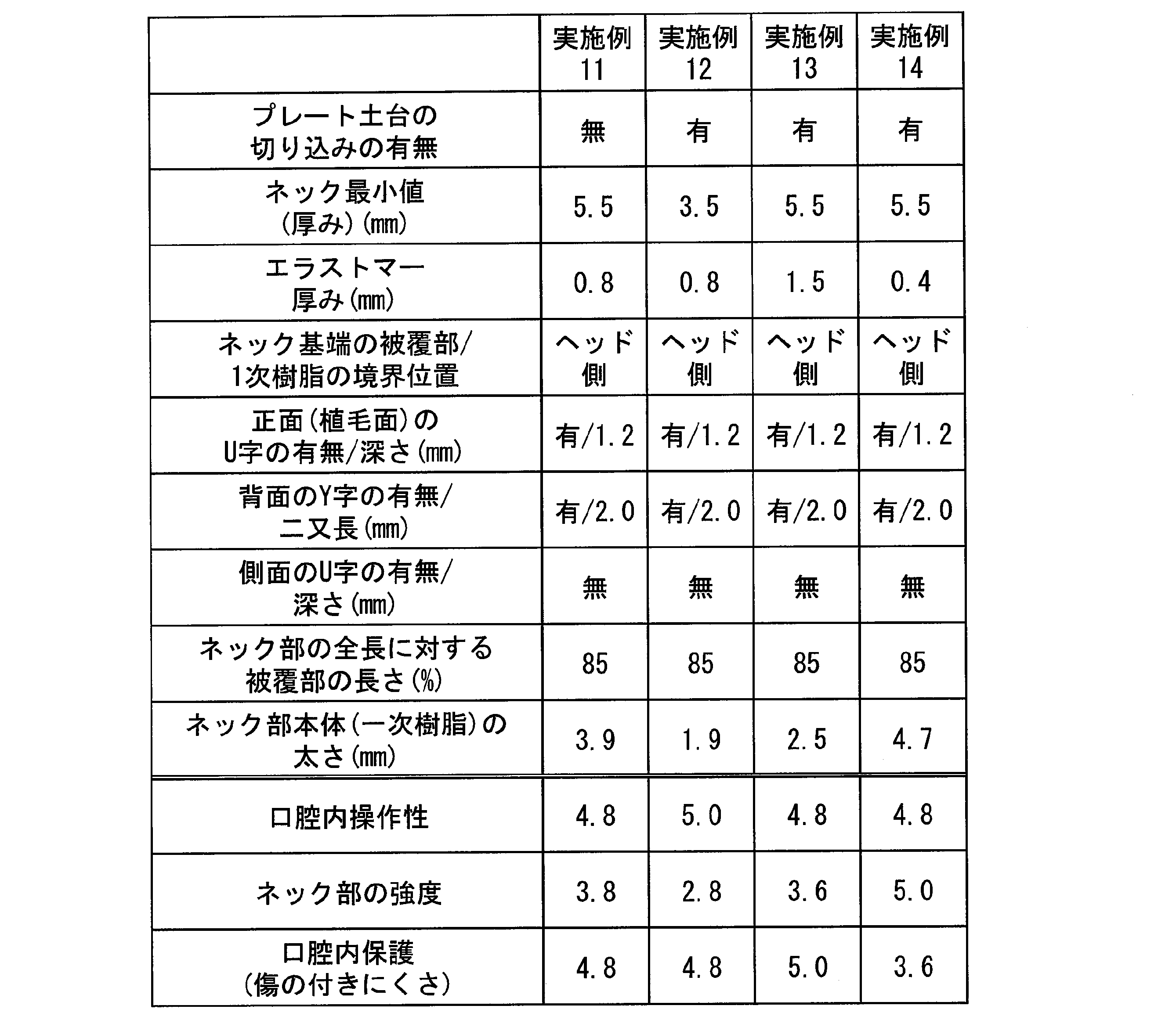
表1に示すように、実施例1~14の歯ブラシは、口腔内操作性が良く、噛み傷も付きにくく、口腔内が十分に保護されるとともに、ネック部14およびハンドル部16の強度も十分に確保された。これらの中でも特に、実施例1~10の歯ブラシは上記効果それぞれが平均的に得られた。
実施例1の歯ブラシは、口腔内操作性、ネック部14およびハンドル部16の強度、口腔内の保護に関して、それぞれ高い評価が得られ、バランスが取れている。
実施例1の歯ブラシを基準にすると、実施例2の歯ブラシは、実施例1に比べてネック部14(硬質樹脂部分:芯)が細いため、口腔内の操作性の面で高い評価が得られた。
実施例3の歯ブラシは、実施例1に比べてネック部14が太いため、ネック部14およびハンドル部16の強度が増した。
実施例4の歯ブラシは、ネック部14を構成するエラストマー樹脂およびポリプロプレンのうち、実施例1の構成に比べてエラストマー樹脂の割合が少し小さい。ネック部14の厚さは実施例1と同様であるため、ネック部14のうちポリプロピレンの割合が少し多くなっている。このため、ネック部14およびハンドル部16の強度は実施例1に比べて高い。
実施例5の歯ブラシは、ネック部14のうちエラストマー樹脂の割合が実施例1よりも多いことから、口腔内の保護を十分に確保できた。
実施例6の歯ブラシは、ネック部14の第1の被覆部18と、プレート嵌合土台部15の挿入部15Bとの境界の位置が部分的に一致している。つまり、ネック部14の露出部33の応力緩和部34の凹部の底がプレート嵌合土台部15の挿入部15Bの表面15bに達しており、ネック部14の周方向の一部においてネック部14の長さ方向全体に第1の被覆部18が存在する。このような構成であっても、実施例1に近い効果を得ることができた。ネック部14およびハンドル部16の強度の面からすると、上記境界の位置は、ネック部14の周方向全体において、プレート嵌合土台部15よりもヘッド部13側に位置している方が望ましいことが分かった。
実施例7の歯ブラシは、応力緩和部34がない構成である。このような構成であっても、実施例1に近い効果を得ることができた。ネック部14およびハンドル部16の強度の面からすると、応力緩和部34を有していた方が望ましいことが分かった。
実施例8の歯ブラシは、応力緩和部34の溝深さが浅い構成である。このような構成であっても、実施例1に近い効果を得ることができた。ネック部14およびハンドル部16の強度の面からすると、応力緩和部34の溝深さが0.8mm以上ある方が望ましいことが分かった。
実施例9の歯ブラシは、応力緩和部34の溝深さが深い構成である。このような構成であっても、実施例1に近い効果を得ることができた。ネック部14およびハンドル部16の強度の面からすると、応力緩和部34の溝深さが1.6mm以下である方が望ましいことが分かった。
実施例10の歯ブラシは、応力緩和部34が植毛面19側ではなく、ネック部14の両側の側面にそれぞれ設けられた構成である。このような構成であっても、実施例1に近い効果を得ることができた。ネック部14およびハンドル部16の強度の面からすると、応力緩和部34は、ネック部14の植毛面19側に位置していることが望ましいことが分かった。
実施例11の歯ブラシは、プレート嵌合土台部15に切り欠き部31が設けられていないものの、口腔内における操作性は良好で口腔内の保護効果も十分に得られた。
実施例12の歯ブラシは、ネック部14の太さが細いため、口腔内における操作性が非常に良い。
実施例13の歯ブラシは、ネック部14を構成するエラストマー樹脂の割合が多いため、口腔内を保護する効果が高い。
実施例14の歯ブラシは、ネック部14を構成するポリプロピレンの割合が多いため、ネック部14からハンドル部16にかけて強度の高い構成となっている。
以上述べたように、第1実施形態の歯ブラシにおいて、ネック部14が細いほど口腔内の操作性は良好となり、第1の被覆部18の厚さが厚いほど口腔内を十分に保護することができる。ネック部14の強度に関しては、ネック部14の太さ(ポリプロピレンの太さ)だけでなく、プレート嵌合土台部15の切り欠き部31の有無、ネック部14における第1の被覆部18と露出部33との境界の位置(エラストマー樹脂およびポリプロピレンの境界の位置)、応力緩和部34の位置等も寄与する。
[第2実施形態]
図9Aは、第2実施形態の歯ブラシの構成を示す正面図である。図9Bは、第2実施形態の歯ブラシの構成を示す背面図である。図10Aは、第2実施形態の歯ブラシ本体の構成を示す正面図である。図10Bは、第2実施形態の歯ブラシ本体の構成を示す背面図である。図11は、第2実施形態の歯ブラシ本体のネック部周辺の構成を示す部分拡大図である。図12は、第2実施形態の歯ブラシ本体のネック部周辺の構成を示す部分拡大図である。
図9Aは、第2実施形態の歯ブラシの構成を示す正面図である。図9Bは、第2実施形態の歯ブラシの構成を示す背面図である。図10Aは、第2実施形態の歯ブラシ本体の構成を示す正面図である。図10Bは、第2実施形態の歯ブラシ本体の構成を示す背面図である。図11は、第2実施形態の歯ブラシ本体のネック部周辺の構成を示す部分拡大図である。図12は、第2実施形態の歯ブラシ本体のネック部周辺の構成を示す部分拡大図である。
図9Aおよび図9Bに示すように、第2実施形態の歯ブラシ40は、例えば生後8ヶ月くらいまでの子供が使用する歯ブラシを想定して構成されている。歯ブラシ40は、歯ブラシ本体40Aと、歯ブラシ本体40Aに対して着脱可能に装着される第2喉突き防止プレート40Bと、を備える。
図10Aおよび図10Bに示すように、歯ブラシ本体40Aは、ヘッド部43、ネック部44、プレート嵌合土台部45およびハンドル部46を有しており、この順に一体に形成されている。本実施形態のハンドル部46は、乳児でも簡単に掴むことができるようにリング状に形成されている。
歯ブラシ本体40Aは、硬質樹脂材料からなる本体部41と、本体部41の少なくとも一部の表面を覆う軟質樹脂材料からなる被覆部42とにより構成されている。
本体部41は、例えば、先の実施形態と同様の硬質樹脂材料を用いて、射出成形により作製することができる。
本体部41は、例えば、先の実施形態と同様の硬質樹脂材料を用いて、射出成形により作製することができる。
被覆部42は、ネック部44の少なくとも一部の表面を被覆する第1の被覆部48と、ハンドル部46の少なくとも一部または全体の表面を被覆する第2の被覆部47とを有する。被覆部42の軟質樹脂材料としては、第1実施形態と同様の材料を用いることができる。
喉突き防止プレート40Bは、第1実施形態と同様の構成のため説明を省略する。
(歯ブラシ本体)
本実施形態では、歯ブラシ40の使用対象者が乳児であることから、歯ブラシ本体40Aの長軸方向全体の長さは、乳児による操作性等を勘案して決定される。例えば、70mm~110mm程度が好ましく、80mm~100mm程度がさらに好ましい。
本実施形態では、歯ブラシ40の使用対象者が乳児であることから、歯ブラシ本体40Aの長軸方向全体の長さは、乳児による操作性等を勘案して決定される。例えば、70mm~110mm程度が好ましく、80mm~100mm程度がさらに好ましい。
ヘッド部43は、図11および図12に示すように、本体部41の先端側に位置し、厚さ方向の両側に植毛面49A,49Bをそれぞれ有している。各植毛面49A,49Bには、軟質樹脂材料からなる複数の毛43aが設けられている。
毛43aの材質としては、特に限定されず、例えば、6-12ナイロン、6-10ナイロン等のポリアミド、PET、PBT、ポリトリメチレンテレフタレート(PTT)、PEN、ポリブチレンナフタレート(PBN)等のポリエステル、PP等のポリオレフィン、オレフィン系エラストマー、スチレン系エラストマー、シリコーン等の合成樹脂材料を用いることができる。これらの樹脂材料は、1種単独で用いられてもよいし、2種以上が組み合わされて用いられてもよい。なお、生後8ヶ月くらいまでの乳幼児は使用中に歯ブラシを噛むことがあるため、毛の材質としてはエラストマー、シリコーンが好ましい。
ネック部44は、ヘッド部43の一端側から延びる部分である。具体的には、図11に示すように、ヘッド部43の平面視形状における、ネック部44よりの隅切を形成する曲線の終点、即ち、隅切を形成する曲線の曲がり方向が変化する境界P1の位置から、挿入部45Bの表面45bまでの長さL3である。
ネック部44は、円形または楕円形の断面形状であり、その幅は長さ方向に一定あるいは拡がっている。ネック部44の長さは、乳児の口腔内のサイズを考慮して決定される。本実施形態では、例えば、図11に示すようにネック部44の長さL3が、2mm~7mm程度であることが好ましく、3mm~6mm程度であることがより好ましい。
また、ネック部44のうち最も細い部分における幅および厚さの寸法(最小径を含む)の範囲と、ネック部44のうち最も太い部分における幅および厚さの寸法(最大径を含む)の範囲は、第1の実施形態と同様である。なお、上述したネック部44の幅および厚さの寸法は、第1の被覆部48の厚さを含んだ寸法である。
本実施形態のハンドル部46は、図10Aおよび図10Bに示すようにリング形状をなし、ネック部44の一端側(ヘッド部43側の端部とは反対側の端部)に設けられている。第1の実施形態と同様に、本体部41のヘッド部43側の端部41aとは反対側の端部41bから、プレート嵌合土台部45の付け根45aまでをハンドル部46と定義すると、図10Aに示すハンドル部46の長さL5は、例えば60mm~70mm程度が好ましい。
あるいは、リング形状のハンドル部46であるため、図10Aに示すように外径D1および内径D2をそれぞれ規定してもよい。ハンドル部46の外径D1および内径D2の差は、正面視におけるハンドル部46の幅Wの寸法に相当し、乳児の掴みやすい寸法に設定されている。また、図12に示すように、側面視におけるハンドル部46の幅Wは、ネック部44の幅W2よりも広い幅で形成されている。
図11および図12に示すように、プレート嵌合土台部45は、ネック部44とハンドル部46との間に設けられ、歯ブラシ本体40Aの中心軸Oの周りに円環状に形成されている。プレート嵌合土台部45は、プレート嵌合部45Aと、プレート嵌合部45Aのヘッド部43側に位置する挿入部45Bと、プレート嵌合部45Aのハンドル部46側に位置する補強部45Cと、を有し、ネック部44およびハンドル部46よりも中心軸Oに直交する方向へ、同心円状に拡がるように形成されている。
プレート嵌合部45A、挿入部45Bおよび補強部45Cは、それぞれ径が異なっており、プレート嵌合部45Aが最も径が大きい。挿入部45Bおよび補強部45Cは、同じ径であってもよいし、異なっていてもよい。挿入部45Bは、喉突き防止プレート20が嵌合する部分であるため貫通孔21の直径に合わせる必要があるが、プレート嵌合土台部45は、ネック部44の強度確保のために設けられた部分であるため、直径の規定は特にない。
挿入部45Bの直径、長軸方向における挿入部45Bの厚さは、第1の実施形態と同様である。また、プレート嵌合部45Aの直径、長軸方向におけるプレート嵌合部45Aの厚さも、第1の実施形態と同様である。
本実施形態のプレート嵌合土台部45には、図10Aに示す表面(植毛面49A側の面)側、および図10Bに示す背面(植毛面49B側の面)側のそれぞれに、図11Aに示す挿入部45B、プレート嵌合部45Aおよび補強部45Cを軸方向に貫く切り欠き部31,31が設けられている。
切り欠き部31,31の切り込み深さは、第1の実施形態と同様に、プレート嵌合土台部45の凸形状がなくなる深さが好ましい。本実施形態においても、切り欠き部31,31のそれぞれの底面が、ハンドル部46の表面とネック部44の表面とを平滑に繋ぐように、これらハンドル部46およびネック部44の各表面とそれぞれ面一となっている。
切り欠き部31の幅および深さの寸法は、第1の実施形態と同様である。
第2の被覆部47は、図9Aおよび図9Bに示すように、ハンドル部46を略全体的に覆っている。本実施形態では、第2の被覆部47に開口47aが設けられており、本体部41の一部が開口47aから露出したデザインとなっている。開口47aの有無、形状等については適宜変更が可能である。
第1の被覆部48は、図10Aおよび図10Bに示すように、ネック部44の少なくとも一部の周方向全体を被覆している。本実施形態では、ネック部44のヘッド部43側の先端側が中心軸O(図11および図12)の軸回り全体が第1の被覆部48によって、被覆されている。本実施形態では、例えば、長さ方向におけるネック部44の全長を100%としたときに、少なくとも40%以上の領域においてネック部44の周方向全体が、第1の被覆部48によって被覆されている。第1の被覆部48によって、ヘッド部43およびネック部44の噛み傷を防ぐことができ、その被覆範囲が50%以上であれば、より好ましい。
また、第1の被覆部48は、ヘッド部43の植毛面49A,49Bを含む略全体と、ネック部44の表裏に設けられた各切り欠き部31,31内の領域の一部を覆うようにして設けられている。
本実施形態では、例えば、ネック部44の総表面積の約60%以上の領域が第1の被覆部48によって被覆されている。第1の被覆部48によって、ヘッド部43およびネック部44の噛み傷を防ぐことができ、その被覆範囲が65%以上であれば、より好ましい。
第2の被覆部47および第1の被覆部48は、プレート嵌合土台部45に設けられた一対の切り欠き部31,31を通じて連続しており、互いに一体に構成されて本実施形態の被覆部42を構成している。被覆部42の厚さは、噛んだときに柔らかさを感じつつ、傷が付きにくい最低限の厚さとする。被覆部12の厚さとしては、第1の実施形態と同様である。
本実施形態では、図11および図12に示すように、ネック部44のプレート嵌合土台部45側の一部、プレート嵌合土台部45における各切り欠き部31,31内の表面の一部、およびハンドル部46のプレート嵌合土台部45側の一部は、第1の被覆部48および第2の被覆部47に沿って被覆されない露出部53となっている。なお、プレート嵌合土台部45の表面は、第1の被覆部48および第2の被覆部47のいずれにも被覆されていない。
露出部53は、第1の被覆部48との境界側に一対の応力緩和部54,54を有している。これら一対の応力緩和部54,54は、歯ブラシ本体40Aの両側の側面にそれぞれ設けられており、切り欠き部31,31の位置とは軸回りにずれた位置にある。
各応力緩和部54,54における第1の被覆部48との境界は、図11に示すように、歯ブラシ本体40Aの正面および背面からそれぞれ見たときに、切り欠き部31,31を通じてハンドル部46側にそれぞれ延出するとともに、ヘッド部43側に向けて突出したY字形状となっている。
応力緩和部54のY字形状は、図11に示すように、応力緩和部54のヘッド部43側の先端において、正面から見たときの半径R1が、例えば0.5mm~3.5mm程度であることが好ましい。また、図12に示すように、応力緩和部54の先端を側面から見たときの半径R2が、例えば1.0mm~2.5mm程度であることが好ましい。
なお、応力緩和部54のY字形状は、半径が異なる複数の曲線を繋いで構成されていてもよい。
なお、応力緩和部54のY字形状は、半径が異なる複数の曲線を繋いで構成されていてもよい。
本実施形態のように、歯ブラシの表裏面のそれぞれに植毛面49A,49Bが設けられている場合は、表面および裏面側のそれぞれに応力緩和部54,54を設けておくことで、表裏の判別が難しい乳児が表裏いずれかのブラシを使用した場合であっても、使用時におけるネック部44への応力集中を緩和することができる。
図11に示すように、応力緩和部54のY字形状の先端側、つまり応力緩和部54におけるヘッド部43側の二股形状の先端において、二股の曲線から直線に変わる地点Mは、プレート嵌合土台部45の開始位置よりもヘッド部43側に位置していることが好ましい。プレート嵌合土台部45の開始位置は、歯ブラシ40の正面側から見たときの挿入部45Bの表面45bの位置である。
応力緩和部54のY字の二股部の深さT2は、応力緩和部54のヘッド部43側の始点である端部41aから上記地点Mまでの長さに相当する。Y字深さT2は、例えば、1.0mm以上、3.5mm以下の範囲内であることが好ましく、2.0mm以上、3.0mm以下の範囲内であることがより好ましい。Y字深さT2を上記範囲内とすることで、軟質樹脂材料からなる第1の被覆部48の撓み挙動が急激に変化するネック部44とプレート嵌合土台部45の境界部分に対して、集中する応力を緩和し、十分な強度を確保することができる。
また、図11に示すように、応力緩和部54のY字形状の後端の長さL4は、少なくとも10mm以上であり、例えば10mm~12mmの範囲内であることが好ましい。上記長さL4は、応力緩和部54のハンドル部46側の直線部分の長さであり、上記地点Mから、プレート嵌合土台部45とハンドル部46との境界地点Nまでの距離に相当する。
図11に示すように、応力緩和部54のY字の二股部の収束点Mから挿入部45Bの表面45bまでの距離L6は、1mm以上であることが好ましい。すなわち、応力緩和部54のY字の二股部の収束点Mの位置は、プレート嵌合土台部45の開始位置から1mm以上離れていることが好ましい。応力緩和部54のY字の二股部の収束点Mを、撓み挙動が急激に変化するプレート嵌合土台部45開始位置からずらすことによって、ブラッシング時の応力を緩和することができる。
また、図12に示す応力緩和部54のネック部44側の始点の幅W3は、ネック部44と同じ幅W2で形成されている。
乳児用の歯ブラシ1では、使用中に喉突きをしないように配慮した構成にするとともに、幼児に比べて乳児の口腔内はさらに小さく、乳歯がすべて生え揃っていないため、歯茎にも優しい構造にする必要がある。また、把持力が弱くても持ちやすい構造にすることも重要である。
そこで、本実施形態では、乳児の口腔内のサイズに合わせてネック部44の長さを幼児用の歯ブラシに比べてさらに短くし、ハンドル形状もリング状にすることでどの角度からも乳児自ら把持できるようにした。また、軟質樹脂材料を用いたブラシ部分をヘッド部43の表裏面にそれぞれ設けることで、表裏の判断が難しい乳児であっても、ヘッド部43を噛むだけで上下いずれの歯に対してもクリーニングが可能である。また、ブラシ部分を軟質樹脂材料により構成しておくことによって、歯茎にも優しく口腔内を傷つけることもない。
上述したように、乳児用の歯ブラシ1は、歯ブラシ本体40Aの所定の位置に喉突き防止プレート20が装着されているが、喉突き防止プレート20が装着されるプレート嵌合土台部45がある構造においては、その部分が強固で撓みにくい。また、大人用の歯ブラシと比較してネック部44の長さが極端に短いため、ブラッシング時の応力がネック部44の付け根に集中しやすい。
そこで、本実施形態では、ヘッド部43の表裏のブラシ部分に合わせて、ネック部44の表裏いずれにも切り欠き部31および応力緩和部54をそれぞれ設け、ブラッシング時の応力を緩和できる構成とした。
また、プレート嵌合土台部45を3段構成とし、ハンドル部46側の付け根に補強部45Cをさらに設けた構成としたことにより、ネック部周辺の強度を向上させることができる。
以下、実施例によって本発明の第2実施形態について具体的に説明するが、本発明は以下の記載によっては限定されない。
評価には、一次材質にポリプロピレン、二次材質にオレフィン系エラストマーを用いて作製した歯ブラシを用いた。
評価には、一次材質にポリプロピレン、二次材質にオレフィン系エラストマーを用いて作製した歯ブラシを用いた。
[口腔内の操作性]
試験者として、乳幼児5人によるブラッシング試験を行い、口腔内における操作性のしやすさについて、保護者の観点から以下の基準で評価した。
≪評価基準≫
5:良い
4:やや良い
3:どちらでもない
2:やや悪い
1:悪い
試験者として、乳幼児5人によるブラッシング試験を行い、口腔内における操作性のしやすさについて、保護者の観点から以下の基準で評価した。
≪評価基準≫
5:良い
4:やや良い
3:どちらでもない
2:やや悪い
1:悪い
[ネック部の強度]
植毛面49Aを水平および上向きにして、歯ブラシのハンドル部46をクランプで把持して固定した。植毛面49Aに錘2kgがつながったワイヤーを掛けて錘を自由落下させ、ネック部44が破断したときの植毛面49Aに対する最大荷重(N)を測定した(n=5)。この測定値の平均値を下記評価基準に分類し、ヘッド部43の強度を評価した。
≪評価基準≫
5:100N以上
4:80N以上100N未満
3:60N以上80N未満
2:40N以上60N未満
1:40N未満
植毛面49Aを水平および上向きにして、歯ブラシのハンドル部46をクランプで把持して固定した。植毛面49Aに錘2kgがつながったワイヤーを掛けて錘を自由落下させ、ネック部44が破断したときの植毛面49Aに対する最大荷重(N)を測定した(n=5)。この測定値の平均値を下記評価基準に分類し、ヘッド部43の強度を評価した。
≪評価基準≫
5:100N以上
4:80N以上100N未満
3:60N以上80N未満
2:40N以上60N未満
1:40N未満
[口腔内の保護(傷のつきにくさ)]
使用後サンプル5本の傷の程度を目視評価にて、各サンプルにつき下記の基準にて専門家パネル5名の平均点を算出した。
≪評価基準≫
5:全く傷なし
4:第1の被覆部(エラストマー)の表面に凹み傷が1個所にあり
3:第1の被覆部(エラストマー)の表面に凹み傷が複数個所にあり
2:第1の被覆部(エラストマー)の表面に1個所の亀裂あり
1:第1の被覆部(エラストマー)の表面に複数個所の亀裂あり
使用後サンプル5本の傷の程度を目視評価にて、各サンプルにつき下記の基準にて専門家パネル5名の平均点を算出した。
≪評価基準≫
5:全く傷なし
4:第1の被覆部(エラストマー)の表面に凹み傷が1個所にあり
3:第1の被覆部(エラストマー)の表面に凹み傷が複数個所にあり
2:第1の被覆部(エラストマー)の表面に1個所の亀裂あり
1:第1の被覆部(エラストマー)の表面に複数個所の亀裂あり
実施例1~9の歯ブラシの仕様と評価結果を表3に示す。

表3に示すように、実施例1~8の歯ブラシは、口腔内操作性が良く、噛み傷も付きにくく、口腔内が十分に保護されるとともに、ネック部44およびハンドル部46の強度も十分に確保された。これらの中でも特に、実施例1の歯ブラシは各項目において高い評価が得られた。
実施例1の歯ブラシは、口腔内操作性、ネック部44およびハンドル部46の強度、口腔内の保護に関して、それぞれ高い評価が得られ、バランスが取れている。
実施例1の歯ブラシを基準にすると、実施例2の歯ブラシは、口腔内操作性や口腔内保護については実施例1と同様の評価が得られた。ネック部44の強度については、切り欠き部31がある方が望ましいことが分かった。
実施例3の歯ブラシは、ネック部44の第1の被覆部48と、プレート嵌合土台部45の挿入部45Bとの境界の位置が部分的に一致しており、応力緩和部54がない構成である。このような構成であっても、口腔内操作性や口腔内保護については、実施例1と同様の評価が得られた。ネック部44の強度については、切り欠き部31がある方が望ましいことが分かった。
実施例4の歯ブラシは、応力緩和部54がない構成である。このような構成であっても、口腔内操作性や口腔内保護については、実施例1と同様の評価が得られた。また、ネック部44の強度については、やはり応力緩和部54を有していた方が望ましいことが分かった。
実施例5の歯ブラシは、Y字形状の二股部の長さが1.0mmと短い構成である。このような構成であっても、口腔内操作性や口腔内保護については、実施例1と同様の評価が得られた。
実施例6の歯ブラシは、Y字形状の二股部の長さが3.9mmと長い構成である。この構成の場合、口腔内操作性や口腔内保護について実施例1と同様の評価が得られたとともに、ネック部44の強度に関しては実施例1よりも高い評価が得られた。
実施例5,6から、ネック部44の強度を高めるためには、Y字形状の二股部の長さが長いことが好ましいことが分かった。
実施例6の歯ブラシは、Y字形状の二股部の長さが3.9mmと長い構成である。この構成の場合、口腔内操作性や口腔内保護について実施例1と同様の評価が得られたとともに、ネック部44の強度に関しては実施例1よりも高い評価が得られた。
実施例5,6から、ネック部44の強度を高めるためには、Y字形状の二股部の長さが長いことが好ましいことが分かった。
実施例7の歯ブラシは、実施例1の歯ブラシに比べるとネック部44のうち、一次樹脂からなるネック部本体の太さが4mmと細い構成のため、口腔内操作性および口腔内保護の評価が高い。
実施例8の歯ブラシは、ネック部44(ネック部本体)の太さが7mmと太い構成ため、ネック部44の強度について高い評価が得られた。
実施例7、8から、ネック部44の強度と、口腔内操作性および口腔内保護とは、トレードオフの関係にあり、双方のバランスからネック部44の太さを設定することが望ましいことが分かった。
実施例8の歯ブラシは、ネック部44(ネック部本体)の太さが7mmと太い構成ため、ネック部44の強度について高い評価が得られた。
実施例7、8から、ネック部44の強度と、口腔内操作性および口腔内保護とは、トレードオフの関係にあり、双方のバランスからネック部44の太さを設定することが望ましいことが分かった。
実施例9の歯ブラシは、ネック部44の全長に対する第1の被覆部48の長さが30%とされた構成である。この構成の場合、口腔内操作性については実施例1と同様の評価が得られたが、ネック部44の強度、口腔内保護について実施例1に比べてかなり低い評価となった。このことから、ネック部44の強度、口腔内保護については、ネック部44の全長に対する第1の被覆部48の長さが40%以上であることが望ましい。
以上述べたように、第2実施形態の歯ブラシにおいて、ネック部44が細いほど口腔内の操作性は良好となり、第1の被覆部48の厚さが0.8mmの場合、口腔内を十分に保護することができる。ネック部44の強度に関しては、ネック部44の太さ(ポリプロピレンの太さ)だけでなく、プレート嵌合土台部45の切り欠き部31の有無、ネック部44におけるエラストマー樹脂およびポリプロピレンの境界の位置、応力緩和部54の位置、Y字形状の二股部の長さ等も寄与する。
以上、添付図面を参照しながら本発明に係る好適な実施形態について説明したが、本発明は係る例に限定されないことは言うまでもない。当業者であれば、特許請求の範囲に記載された技術的思想の範疇内において、各種の変更例または修正例に想到し得ることは明らかであり、それらについても当然に本発明の技術的範囲に属するものと了解される。
上述した第1実施形態および第2実施形態では、歯ブラシ本体と喉突き防止プレートとが別部材とされており、歯ブラシ本体に対して、喉突き防止プレートが着脱可能に装着される構成となっていたが、歯ブラシ本体と喉突き防止プレートが一体の構成であってもよい。
第1実施形態では、歯ブラシ本体10のプレート嵌合土台部15が2段構成(プレート嵌合部15A、挿入部15B)となっているが、1段のみ(プレート嵌合部15Aあるいは挿入部15Bのみ)の構成であってもよく、第2実施形態のように、3段以上の構成であってもよい。この場合は、最も拡径された土台部分で直径等を規定することが好ましい。また、第2実施形態においても、プレート嵌合土台部45の構成は上記した構成に限られず、例えば1段もしくは2段で構成されていてもよい。
また、応力緩和部の形状も上述した各実施形態で示した形状に限られず、例えば、U字形状の応力緩和部とY字形状の応力緩和部とを組み合わせてもよい。
1,40…歯ブラシ、10,40A…歯ブラシ本体、11,41…本体部、12,42…被覆部、13,43…ヘッド部、14,44…ネック部、15…プレート嵌合土台部、15A…嵌合部、15B…挿入部、15b,20a…表面、16,46…ハンドル部、17,47…第2の被覆部、18,48…第1の被覆部、19,49A,49B…植毛面、20…喉突き防止プレート、21…貫通孔、23…プレート側嵌合受け部、31…切り欠き部、33…露出部、34,54…応力緩和部
Claims (14)
- 歯ブラシ本体と、前記歯ブラシ本体に設けられる喉突き防止プレートと、を備え、
前記歯ブラシ本体は、
植毛面を有するヘッド部と、
前記ヘッド部の後端から延びるネック部と、
前記ネック部の前記ヘッド部とは反対側に位置するハンドル部と、
前記ネック部と前記ハンドル部との間に配置されたプレート嵌合土台部と、を有する硬質樹脂材料からなる本体部と、
前記ネック部の少なくとも一部の表面を被覆する軟質樹脂材料からなる第1の被覆部と、を有して構成されている、
ことを特徴とする歯ブラシ。 - 前記プレート嵌合土台部の周方向の一部に切り欠き部が設けられており、
前記第1の被覆部と、前記切り欠き部を通じて、前記ハンドル部の少なくとも一部を被覆する第2の被覆部と、が連続し、一体となっている、
請求項1に記載の歯ブラシ。 - 前記プレート嵌合土台部は、
前記喉突き防止プレートのプレート側嵌合受け部に嵌合する嵌合部と、
前記プレート側嵌合受け部の貫通孔内に挿入される挿入部と、を有し、
前記切り欠き部は、前記嵌合部および前記挿入部を貫通する、請求項1に記載の歯ブラシ。 - 前記ネック部の前記ハンドル部側の端部には、前記プレート嵌合土台部に隣接して、前記第1の被覆部で被覆されない露出部が存在する、請求項1に記載の歯ブラシ。
- 前記露出部は、前記第1の被覆部との境界側に少なくとも一つの応力緩和部を有しており、
前記応力緩和部の前記第1の被覆部との境界が前記ハンドル部側に凹むU字形状をなす、請求項4に記載の歯ブラシ。 - 前記第1の被覆部は、長さ方向における前記ネック部の全長を100%としたときに、少なくとも60%以上の領域においてネック部の周方向全体を被覆している、請求項5に記載の歯ブラシ。
- 前記応力緩和部のU字深さは、0.8mm以上、1.6mm以下の範囲内である、請求項5に記載の歯ブラシ。
- 前記露出部は、前記第1の被覆部との境界側に少なくとも一つの応力緩和部を有し、
前記応力緩和部の前記第1の被覆部との境界が前記ハンドル部側に凹むY字形状をなし、
前記切り欠き部を通じて、前記第1の被覆部と、前記ハンドル部の少なくとも一部を被覆する第2の被覆部と、が連続し、互いに一体となっている、請求項4に記載の歯ブラシ。 - 前記ネック部は、円形または楕円形の断面形状であり、幅が長さ方向に一定あるいは拡がっており、
前記第1の被覆部は、長さ方向における前記ネック部の全長を100%としたときに、少なくとも40%以上の領域においてネック部の周方向全体を被覆している、請求項8に記載の歯ブラシ。 - 前記応力緩和部のY字深さは、1.0mm以上、3.5mm以下の範囲内である、請求項8に記載の歯ブラシ。
- 前記応力緩和部は、前記ネック部の周方向のうち前記植毛面と同じ側に設けられている、請求項5に記載の歯ブラシ。
- 前記応力緩和部の前記ネック部側の始点は、前記ネック部と同じ幅で形成されている、請求項5に記載の歯ブラシ。
- 前記ネック部の幅および厚さの最小値が、4.0mm以上、7.0mm以下である、請求項1に記載の歯ブラシ。
- 前記ヘッド部の表面が前記第1の被覆部によって覆われている、請求項1に記載の歯ブラシ。
Priority Applications (2)
| Application Number | Priority Date | Filing Date | Title |
|---|---|---|---|
| KR1020217008576A KR102739318B1 (ko) | 2018-12-28 | 2019-12-26 | 칫솔 |
| CN201990001250.3U CN216983992U (zh) | 2018-12-28 | 2019-12-26 | 牙刷 |
Applications Claiming Priority (2)
| Application Number | Priority Date | Filing Date | Title |
|---|---|---|---|
| JP2018246854A JP7142567B2 (ja) | 2018-12-28 | 2018-12-28 | 歯ブラシ |
| JP2018-246854 | 2018-12-28 |
Publications (1)
| Publication Number | Publication Date |
|---|---|
| WO2020138276A1 true WO2020138276A1 (ja) | 2020-07-02 |
Family
ID=71128682
Family Applications (1)
| Application Number | Title | Priority Date | Filing Date |
|---|---|---|---|
| PCT/JP2019/051095 Ceased WO2020138276A1 (ja) | 2018-12-28 | 2019-12-26 | 歯ブラシ |
Country Status (5)
| Country | Link |
|---|---|
| JP (1) | JP7142567B2 (ja) |
| KR (1) | KR102739318B1 (ja) |
| CN (1) | CN216983992U (ja) |
| TW (1) | TWI807151B (ja) |
| WO (1) | WO2020138276A1 (ja) |
Cited By (1)
| Publication number | Priority date | Publication date | Assignee | Title |
|---|---|---|---|---|
| WO2022093968A1 (en) * | 2020-10-27 | 2022-05-05 | Farzin Nina D | Oral device for a baby |
Families Citing this family (1)
| Publication number | Priority date | Publication date | Assignee | Title |
|---|---|---|---|---|
| KR200496138Y1 (ko) * | 2021-12-28 | 2022-11-11 | 주식회사 엠씨알 | 자동차 세차용 휠 클리너 |
Citations (3)
| Publication number | Priority date | Publication date | Assignee | Title |
|---|---|---|---|---|
| JPS57162732U (ja) * | 1981-04-09 | 1982-10-13 | ||
| JP2007160073A (ja) * | 2005-11-16 | 2007-06-28 | Pigeon Corp | 乳歯ブラシ |
| JP2014217400A (ja) * | 2013-04-30 | 2014-11-20 | 花王株式会社 | 乳幼児用歯ブラシ |
Family Cites Families (4)
| Publication number | Priority date | Publication date | Assignee | Title |
|---|---|---|---|---|
| US5830277A (en) | 1995-05-26 | 1998-11-03 | Mattson Technology, Inc. | Thermal processing system with supplemental resistive heater and shielded optical pyrometry |
| CN103110272A (zh) * | 2011-11-16 | 2013-05-22 | 丁加亮 | 儿童牙刷 |
| CN203369547U (zh) * | 2013-07-25 | 2014-01-01 | 潘雨婷 | 一种新型婴儿护理牙刷 |
| CN208144727U (zh) * | 2017-09-19 | 2018-11-27 | 浙江金豪婴童用品有限公司 | 一种儿童硅胶牙刷 |
-
2018
- 2018-12-28 JP JP2018246854A patent/JP7142567B2/ja active Active
-
2019
- 2019-12-25 TW TW108147657A patent/TWI807151B/zh active
- 2019-12-26 KR KR1020217008576A patent/KR102739318B1/ko active Active
- 2019-12-26 WO PCT/JP2019/051095 patent/WO2020138276A1/ja not_active Ceased
- 2019-12-26 CN CN201990001250.3U patent/CN216983992U/zh active Active
Patent Citations (3)
| Publication number | Priority date | Publication date | Assignee | Title |
|---|---|---|---|---|
| JPS57162732U (ja) * | 1981-04-09 | 1982-10-13 | ||
| JP2007160073A (ja) * | 2005-11-16 | 2007-06-28 | Pigeon Corp | 乳歯ブラシ |
| JP2014217400A (ja) * | 2013-04-30 | 2014-11-20 | 花王株式会社 | 乳幼児用歯ブラシ |
Cited By (1)
| Publication number | Priority date | Publication date | Assignee | Title |
|---|---|---|---|---|
| WO2022093968A1 (en) * | 2020-10-27 | 2022-05-05 | Farzin Nina D | Oral device for a baby |
Also Published As
| Publication number | Publication date |
|---|---|
| TW202027648A (zh) | 2020-08-01 |
| JP7142567B2 (ja) | 2022-09-27 |
| TWI807151B (zh) | 2023-07-01 |
| KR102739318B1 (ko) | 2024-12-10 |
| JP2020103705A (ja) | 2020-07-09 |
| KR20210104645A (ko) | 2021-08-25 |
| CN216983992U (zh) | 2022-07-19 |
Similar Documents
| Publication | Publication Date | Title |
|---|---|---|
| US5623739A (en) | Toddler/child toothbrush | |
| JP5269351B2 (ja) | 歯ブラシ | |
| US4654921A (en) | Toothbrushes | |
| US4640273A (en) | Mouth guard for use with a diagnostic instrument | |
| CA2474737C (en) | Teether | |
| US20220125685A1 (en) | Oral Device For A Baby | |
| JP6364641B2 (ja) | 歯ブラシ | |
| US11051604B2 (en) | Infant toothbrush | |
| TWI807151B (zh) | 牙刷 | |
| JP6970491B2 (ja) | 歯ブラシ | |
| JP2005224268A (ja) | 歯間ブラシ | |
| JP6598383B2 (ja) | 歯ブラシ | |
| JP2020075125A (ja) | 液状歯磨き剤塗布ブラシ | |
| JPWO2019230845A1 (ja) | 歯ブラシ | |
| JP6512703B2 (ja) | 歯ブラシ | |
| CN111093430B (zh) | 牙刷 | |
| JP4802584B2 (ja) | 口腔用清掃具及びこれを用いた口腔清掃方法 | |
| JP2000125937A (ja) | 歯ブラシ | |
| JP7698770B2 (ja) | 歯ブラシ | |
| CN113194783A (zh) | 牙刷 | |
| KR200348359Y1 (ko) | 장애인용 칫솔 | |
| JPH0744629U (ja) | プラークコントロール用具 | |
| KR970032544A (ko) | 칫솔 | |
| US20040048228A1 (en) | Disposable dental tray having interlocking handles | |
| JP2022104256A (ja) | 塗布用ブラシ |
Legal Events
| Date | Code | Title | Description |
|---|---|---|---|
| 121 | Ep: the epo has been informed by wipo that ep was designated in this application |
Ref document number: 19904693 Country of ref document: EP Kind code of ref document: A1 |
|
| NENP | Non-entry into the national phase |
Ref country code: DE |
|
| 122 | Ep: pct application non-entry in european phase |
Ref document number: 19904693 Country of ref document: EP Kind code of ref document: A1 |