WO2020137405A1 - 画像処理装置、画像処理方法、及びプログラム - Google Patents
画像処理装置、画像処理方法、及びプログラム Download PDFInfo
- Publication number
- WO2020137405A1 WO2020137405A1 PCT/JP2019/047473 JP2019047473W WO2020137405A1 WO 2020137405 A1 WO2020137405 A1 WO 2020137405A1 JP 2019047473 W JP2019047473 W JP 2019047473W WO 2020137405 A1 WO2020137405 A1 WO 2020137405A1
- Authority
- WO
- WIPO (PCT)
- Prior art keywords
- divided images
- image
- unit
- obstacle
- target
- Prior art date
- Legal status (The legal status is an assumption and is not a legal conclusion. Google has not performed a legal analysis and makes no representation as to the accuracy of the status listed.)
- Ceased
Links
Images





Classifications
-
- G—PHYSICS
- G06—COMPUTING OR CALCULATING; COUNTING
- G06T—IMAGE DATA PROCESSING OR GENERATION, IN GENERAL
- G06T1/00—General purpose image data processing
-
- H—ELECTRICITY
- H04—ELECTRIC COMMUNICATION TECHNIQUE
- H04N—PICTORIAL COMMUNICATION, e.g. TELEVISION
- H04N23/00—Cameras or camera modules comprising electronic image sensors; Control thereof
- H04N23/60—Control of cameras or camera modules
Definitions
- the present invention relates to an image processing device, an image processing method, and a program, and more particularly, to an image processing device, an image processing method, and a program that perform panorama composition of images captured by dividing.
- Patent Document 1 describes a technique for detecting a deformation such as a crack from a photographed image of a concrete surface.
- the inspection range of the structure to be inspected for example, the wall surface of the building
- the divided images obtained by dividing the inspection range are acquired, and the combined image obtained by panorama combining the divided images Used.
- various techniques have been proposed for the purpose of increasing the accuracy of panorama synthesis.
- Patent Document 2 describes a technique for acquiring a panoramic composite image with a high dynamic range.
- the technique described in Patent Document 2 describes that when a whiteout area exists in the overlapping area, panorama synthesis is performed based on the overlapping area excluding the whiteout area.
- a gondola is used as a means of transportation for the inspector.
- the gondolas are used to inspect the entire wall from low to high. Then, the inspector moves the gondola and acquires a photographed image of the inspection target as a record of the inspection result. Specifically, the inspector moves the gondola and directly faces the wall surface to acquire the divided images to be inspected.
- the overlapping regions are provided to acquire each divided image, but when the divided images are acquired according to the above process, the marking is captured. Since it will be erased later, the marking may not exist in the overlapping region of the next divided image.
- Patent Document 1 describes that a deformation is detected from a captured image, it does not mention the technique of panorama synthesis.
- Patent Document 2 does not mention the technique of panorama synthesis when a common object exists or does not exist in the overlapping area of each divided image.
- the present invention has been made in view of such circumstances, and an object thereof is an image processing device and an image processing device capable of accurately performing a panoramic synthesis of a plurality of divided images obtained by dividing and photographing the surface of a structure. It is to provide a processing method and a program.
- An image processing apparatus which is an aspect of the present invention for achieving the above object, includes an image acquisition unit that acquires a plurality of divided images obtained by dividing and photographing a surface of a structure, and a plurality of divided images.
- a failure target detection unit that detects a failure target that is an obstacle to panorama synthesis, a feature point extraction unit that extracts a feature point by excluding the failure target detected in each of the plurality of divided images, and a plurality of divided images
- a first combination processing unit that panorama-composes a plurality of divided images to generate a combined image by matching feature points, and an output unit that outputs the combined image.
- the obstacle target detection unit detects the obstacle target that is an obstacle for panorama synthesis because a common object exists or does not exist in the overlapping area of each divided image, and the detected obstacle is detected.
- Feature points are extracted by excluding objects.
- the panorama-synthesized composite image is generated by matching the extracted feature points, the panorama synthesis can be performed with high accuracy.
- the image processing device includes a display unit that displays the composite image.
- the image processing device includes a display unit that displays a plurality of divided images, and a feature point receiving unit that receives a correction of a feature point in the plurality of divided images.
- the image processing device includes a display unit that displays a plurality of divided images, and a failure target reception unit that receives correction of a failure target in the plurality of divided images.
- the obstacle target is a drawing portion marked on the structure, a user's body, an insect, or an animal reflected in capturing the divided images.
- the obstacle target is a drawing portion where marking is made for surface damage
- the second obstacle processing unit generates a synthetic obstacle target by synthesizing the obstacle targets in a plurality of divided images.
- the output unit superimposes the synthetic obstacle target on the synthetic image or the drawing of the structure.
- the first synthesis processing unit determines the order of superimposing the panoramic synthesis of the plurality of divided images based on the presence/absence of visualization of the obstacle target.
- the image processing apparatus is a drawing location where the failure target is, the drawing location has information about the surface state of the structure, and an information reading unit that reads information about the surface state of the drawing location.
- the information reading unit recognizes the shape of the drawing place or the color of the drawing place and reads the information about the surface state.
- the output unit outputs the information regarding the surface state read by the information reading unit.
- An image processing method includes a step of acquiring a plurality of divided images obtained by dividing and photographing a surface of a structure, and a step of determining an obstacle target that becomes an obstacle in panorama synthesis in the plurality of divided images.
- the step of detecting, the step of extracting the feature points by excluding the obstacle target detected in each of the plurality of divided images, and the matching of the feature points of the plurality of divided images, the panorama composite of the plurality of divided images And generating a composite image, and outputting the composite image.
- a program includes a step of acquiring a plurality of divided images obtained by dividing and photographing a surface of a structure, and detecting an obstacle target that is an obstacle to panorama synthesis in the plurality of divided images.
- the step, the step of extracting the feature points by excluding the obstacle target detected in each of the plurality of divided images, and the step of matching the feature points of the plurality of divided images, the panorama composite of the plurality of divided images is performed.
- a computer is made to perform the step which produces
- an obstacle target that is an obstacle for panorama synthesis is detected, feature points are extracted by removing the detected obstacle target, and the extracted feature points are matched to perform panorama synthesis.
- a well-synthesized composite image can be obtained.
- FIG. 1 is a conceptual diagram showing a computer equipped with an image processing apparatus.
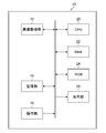
- FIG. 2 is a block diagram showing an example of the hardware configuration of the image processing apparatus.
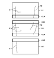
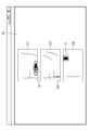
- FIG. 3 is a diagram conceptually showing a plurality of divided images.
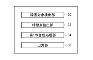
- FIG. 4 is a diagram showing a main functional configuration of the image processing apparatus.
- FIG. 5 is a diagram for explaining extraction of feature points in each of the divided images.
- FIG. 6 is a diagram illustrating panorama synthesis.
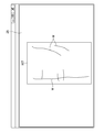
- FIG. 7 is a diagram showing an example of display of a composite image.
- FIG. 8 is a flowchart illustrating the image processing method.
- FIG. 9 is a diagram illustrating a main functional configuration example of the image processing apparatus.
- FIG. 10 is a diagram showing an example in which feature points are added.
- FIG. 11 is a diagram showing an example in which feature points are added.
- FIG. 12 is a diagram illustrating an example in which a failure target is added.
- FIG. 13 is a diagram illustrating a main functional configuration example of the image processing apparatus.
- FIG. 14 is a diagram illustrating generation of a synthetic fault target.
- FIG. 15 is a diagram showing an example in which a synthetic obstacle target is superimposed and displayed on a CAD diagram.
- FIG. 16 is a diagram for explaining composition of divided images.
- FIG. 17 is a diagram showing an example of the main functional configuration of the image processing apparatus.
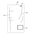
- FIG. 18 is a diagram conceptually showing the information indicated by chalk in the divided images.
- FIG. 1 is a conceptual diagram showing a computer in which the image processing apparatus 10 of the present invention is installed.
- the computer includes a computer main body 10 a, a display unit 26, and an operation unit 18.
- the display unit 26 displays a divided image or a panorama-combined composite image.
- the inspector (user) confirms the divided image or the composite image displayed on the display unit 26, and inputs a command such as a correction to the operation unit 18 as necessary.
- FIG. 2 is a block diagram showing an example of the hardware configuration of the image processing apparatus 10.
- a personal computer or a workstation can be used as the image processing apparatus 10 for the structure shown in FIG.
- the hardware configuration of the image processing apparatus 10 mainly includes an image acquisition unit 12, a storage unit 16, an operation unit 18, a CPU (Central Processing Unit) 20, a RAM (Random Access Memory) 22, and a ROM (Read Only Memory). ) 24 and a display unit 26.
- CPU Central Processing Unit
- RAM Random Access Memory
- ROM Read Only Memory
- the image acquisition unit 12 acquires an image obtained by dividing the structure to be inspected and photographing (divided photographing). For example, the image acquisition unit 12 acquires the divided images when the image captured by the camera is input to the image processing apparatus 10.
- Structures to be inspected include concrete structures such as buildings, bridges, and tunnels.
- the wall surface of the building will be described as an example of the structure to be inspected.
- FIG. 3 is a diagram conceptually showing a plurality of divided images acquired by the image acquisition unit 12.
- the divided image 101, the divided image 103, and the divided image 105 acquired by the image acquisition unit 12 are taken by moving the wall surfaces in the vertical direction so as to have overlapping regions.
- the divided image 101 and the divided image 103 are overlapped by the overlapping area 101A and the overlapping area 103B. Further, the divided image 103 and the divided image 105 overlap with each other by the overlapping area 103A and the overlapping area 105B.
- the overlapping area is an area in which the same subject area is shown, and ideally the same image when there is no obstacle target, which will be described later.
- the divided image 101, the divided image 103, and the divided image 105 have a drawing portion M in which a cracked portion on the wall surface is marked with chalk.
- the divided image 101 is photographed, the divided image 103 is photographed thereafter, and the divided image 105 is photographed thereafter.
- the photographer erases the chalk drawing portion M in the range taken by the divided image 101, moves to the photographing position of the divided image 103 with a gondola, and takes the divided image 103.
- the photographer erases the chalk drawing portion M in the range photographed with the divided image 103 after photographing the divided image 103, moves to the photographing position of the divided image 105 with a gondola, and photographs the divided image 105.
- the drawing area M may or may not exist in the overlapping area.
- the drawing portion M existing in the overlapping area 101A has a portion not existing in the overlapping area 103B.
- the divided image 103 and the divided image 105 are overlapped by the overlapping area 103A and the overlapping area 105B, and the drawing location M existing in the overlapping area 103A does not exist in the overlapping area 105B.
- the drawing location M that exists or does not exist in the overlapping area becomes an obstacle target that cannot properly perform panorama composition. That is, if feature points used when performing panorama synthesis in the area of the drawing location M are detected, feature points that cannot be matched will occur, and panorama synthesis will not be performed properly.
- the obstacle target is not limited to the drawing portion M that becomes an obstacle to panorama synthesis, and it exists in one divided image even though the same portion is photographed, and the other divided image. Any subject that does not exist in. For example, the body, insect, or animal of the user, which is reflected in capturing the divided images, may be the obstacle target. Therefore, the image processing apparatus 10 implements panorama synthesis with high accuracy by excluding such obstacle targets that obstruct the panorama synthesis.
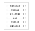
- FIG. 4 is a diagram showing a main functional configuration of the image processing apparatus 10, and is a block diagram showing functions realized by hardware such as the CPU 20, the storage unit 16, the RAM 22, and the ROM 24.
- the image processing device 10 mainly includes a failure target detection unit 30, a feature point extraction unit 32, a first synthesis processing unit 34, and an output unit 36.
- the failure target detection unit 30 detects a failure target that becomes an obstacle in panorama synthesis in a plurality of divided images. Specifically, the obstacle target detection unit 30 detects a drawing portion M in which a damaged portion is marked with chalk or the like, a user's body, an insect, or an animal that is reflected at the time of shooting the divided images as an obstacle target.
- the failure target detection unit 30 can detect the failure target by various methods. For example, the failure target detection unit 30 can detect the failure target by performing image processing on the divided images.
- the feature point extraction unit 32 extracts the feature point P by excluding the obstacle target detected in each of the plurality of divided images. Specifically, the feature point extraction unit 32 detects the feature point P in an area other than the failure target area detected by the failure target detection unit 30.
- the extraction of the feature points P of the feature point extraction unit 32 is performed by using a known technique such as SIFT (scale invariant feature transform) and SURF (speeded up robust features).
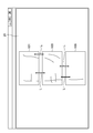
- FIG. 5 is a diagram for explaining extraction of the feature point P in each of the divided images (divided image 101, divided image 103, and divided image 105).
- the feature point extraction unit 32 extracts the feature points P in the divided image 101, the divided image 103, and the divided image 105.
- the drawing point M detected by the obstacle target detection unit 30 is excluded to extract the feature point P.
- the drawing point M is shown by a solid line and is excluded from the extraction target area of the characteristic point P in the characteristic point extraction unit 32.
- Extracting the feature point P by excluding the drawing point M means that even if there is a point that can be extracted as the feature point P in the drawing point M, if the feature point P is not extracted, the feature point P is extracted in an area other than the area of the drawing point M. Means to do.
- the first combining processing unit 34 panorama-combines the plurality of divided images by matching the feature points P of the plurality of divided images to generate a combined image.
- the first synthesis processing unit 34 matches the feature points P extracted by a known method. For example, the first synthesis processing unit 34 obtains a projective transformation matrix by matching the feature points P, and performs panorama synthesis based on the projective transformation matrix.
- the output unit 36 outputs a composite image.
- the output form of the composite image of the output unit 36 is not particularly limited.
- the output unit 36 outputs a composite image in the image file format desired by the user.
- the composite image output by the output unit 36 is displayed on the display unit 26, for example.
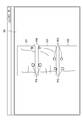
- FIG. 6 is a diagram illustrating panorama composition.
- FIG. 6(A) shows that the extracted feature points P are matched
- FIG. 6(B) shows a panorama-combined image based on the matched feature points P. There is.
- FIG. 6A shows that matching is performed at the extracted feature points P described in FIG.
- the matching of the feature points P is indicated by an arrow S. Since the feature P is extracted by excluding the drawing portion M, the matching of the feature points P is appropriately performed as indicated by the arrow S.
- a panorama composited image 107 is shown based on the matching of the arrow S.
- the overlapping area 101A and the overlapping area 103B are overlapped with each other, and the overlapping area 103A and the overlapping area 105B are overlapped with each other, so that the composite image 107 is generated.
- the feature point P is extracted in the area where the drawing location M is excluded, and the panorama synthesis with high accuracy is performed based on the feature point P.
- FIG. 7 is a diagram showing an example of a display of the composite image 107 on the display unit 26.
- the composite image 107 is displayed on the display unit 26, and the user can confirm the displayed composite image 107.
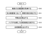
- FIG. 8 is a flowchart illustrating an image processing method using the image processing device 10.
- the image acquisition unit 12 of the image processing apparatus 10 acquires a plurality of divided images (step S10).
- the obstacle target detection unit 30 detects an obstacle target that becomes an obstacle in panorama synthesis in each divided image (step S11).
- the feature point extracting unit 32 extracts the feature point P by excluding the obstacle target of the divided image (step S12).
- the first combination processing unit 34 matches the extracted feature points P, and panoramic-combines a plurality of divided images based on the matched information to generate a combined image 107 (step S13).
- the output unit 36 outputs the composite image 107 (step S14).
- the obstacle target detection unit 30 causes an obstacle in panorama synthesis because a common object exists or does not exist in the overlapping region of each divided image.
- the obstacle target is detected, the detected obstacle target is excluded, and the feature point P is extracted.
- a panorama-combined composite image is generated by matching the extracted feature points P.
- a CPU is used as an example of the processor, but the present invention is not limited to this.
- an FPGA Field Programmable Gate Array
- a processor having a circuit configuration specifically designed to execute a specific process such as ASIC (Application Specific Integrated Circuit). Certain dedicated electrical circuits may be used.
- each function or each processing unit may be configured by one of these various processors, or two or more processors of the same type or different types (for example, a plurality of FPGAs or a combination of a CPU and an FPGA). ).
- the plurality of processing units may be configured by one processor.
- a processor As an example of configuring a plurality of processing units by one processor, firstly, as represented by a computer such as a client or a server, one processor is configured by a combination of one or more CPUs and software. There is a form in which the processor functions as a plurality of processing units.
- SoC system-on-chip
- a processor that realizes the functions of the entire system including a plurality of processing units by one integrated circuit (IC) chip is used. is there.
- a computer-readable recording medium non-transitory recording medium that records such a program, or a computer in which such a program can be installed
- the present invention can be applied.
- FIG. 9 is a diagram showing an example of the main functional configuration of the image processing apparatus 10 of this embodiment.
- the parts already described in FIG. 4 are designated by the same reference numerals and the description thereof will be omitted.
- the image processing apparatus 10 mainly includes a failure target detection unit 30, a feature point extraction unit 32, a first synthesis processing unit 34, an output unit 36, a feature point reception unit 38, and a failure target reception unit 40.
- the feature point receiving unit 38 receives the correction of the feature point P in the divided image.
- the divided images are displayed on the display unit 26, and the user adds the feature points P not automatically extracted by the image processing or deletes the erroneously extracted feature points P while checking the displayed divided images.
- a correction command is input via the operation unit 18.
- FIG. 10 is a diagram showing an example of a case where the feature point P is added to the divided image displayed on the display unit 26.
- the user operates the divided images 101, 103, and 105 displayed on the display unit 26.
- a feature point P is added via the unit 18.
- the user inputs a command for correcting the feature point P by connecting the matching feature points P with the straight line L via the operation unit 18.
- the feature point receiving unit 38 receives the input correction command and reflects it in the extraction result of the feature point extracting unit 32. That is, the feature points P connected by the straight line L are used for panorama composition, and the accuracy of panorama composition is improved.
- FIG. 11 is a diagram showing another example of the case where the feature point P is added to the divided image displayed on the display unit 26.
- the user selects the feature points P for the divided images 101, 103, and 105 displayed on the display unit 26.
- the matching feature point P is marked with the same mark.
- the user inputs a command to add a feature point by marking a matching feature point P with the same mark using a quadrangle PA, a triangle PB, a parallelogram PC, and a circle PD via the operation unit 18.
- the feature point receiving unit 38 receives the input instruction and reflects it on the extraction result of the feature point extracting unit 32. Then, the feature points P marked with the same mark are used for panorama composition, and the accuracy of panorama composition is improved.
- the failure target receiving unit 40 receives the correction of the failure target in the plurality of divided images.
- the divided images are displayed on the display unit 26, and the user inputs the obstacle target not automatically detected by the image processing through the operation unit 18 while recognizing the displayed divided images, or is erroneously detected.
- the correction target is input by erasing the faulty object through the operation unit 18.
- the failure target reception unit 40 receives the input correction, and the failure target detection unit 30 reflects the correction received by the failure target reception unit 40 in the detection result.
- FIG. 12 is a diagram showing an example of a case where a fault target is added to the divided image displayed on the display unit 26.
- the failure target detection unit 30 cannot detect, that is, when there is an unexpected failure target or the detection is insufficient
- the divided image 101, the divided image 103, and the divided image 103 displayed on the display unit 26 are displayed.
- the user adds a failure target to the divided image 105 via the operation unit 18.
- the user confirms the divided images displayed on the display unit 26, and if the unexpected failure target or the assumed failure target is insufficiently detected, the user inputs the failure target via the operation unit 18.
- An unexpected failure target O exists in the divided image 101 and the divided image 105, and a portion SS in which the drawing portion M is insufficiently detected by chalk exists in the divided image 103.
- the user designates the area of the failure target O or traces the location SS through the operation unit 18 and inputs a correction command.
- the user inputs the feature point P and the obstacle target, and the panorama synthesis is performed using the input feature point P or the obstacle target. Therefore, it is possible to perform more accurate panorama synthesis.
- the obstacle targets detected in each divided image are combined to generate a combined obstacle target.
- FIG. 13 is a diagram showing an example of the main functional configuration of the image processing apparatus 10 of this embodiment.
- the parts already described in FIG. 4 are designated by the same reference numerals and the description thereof will be omitted.
- the image processing device 10 mainly includes a failure target detection unit 30, a feature point extraction unit 32, a first combination processing unit 34, an output unit 36, and a second combination processing unit 42.
- the second synthesis processing unit 42 synthesizes the obstacle targets of the divided images to generate a synthesized obstacle target. Specifically, when the obstacle target is the drawing portion M, the obstacle targets of the respective divided images detected by the obstacle target detection unit 30 are combined to generate a combined obstacle target 123.
- the composite obstacle target 123 is superimposed by the output unit 36 on the composite image 121 or on the drawing of the structure.
- the second synthesis processing unit like the first synthesis processing, matches the feature points P of the divided images to synthesize the obstacle targets of the divided images to generate the synthetic obstacle target 123.
- FIG. 14 is a diagram for explaining the generation of the synthetic fault target 123.
- FIG. 14A shows a plurality of divided images (divided image 101, divided image 103, and divided image 105 described in FIG. 3) acquired by the image acquisition unit 12.
- FIG. 14B shows the synthesis failure target 123 generated by the second synthesis processing unit 42 and the synthesis image 121 generated by the first synthesis processing unit 34.
- FIG. 14C shows an overwrite image 125 in which the synthesis failure target 123 is overwritten on the synthesis image 121.
- the second synthesis processing unit 42 obtains a projective transformation matrix by matching the feature points P of the divided image 101, the divided image 103, and the divided image 105, and synthesizes and synthesizes the drawing place M in each divided image. Obtain the obstacle target 123. By being synthesized in this way, the synthesis obstacle target 123 reproduces the appearance before the drawing location M is erased. Then, the output unit 36 overwrites the generated synthetic obstacle target 123 on the synthetic image 121 and outputs the overwritten image 125. The overwriting image 125 is represented without the drawing portion M being cut off because the synthesis failure target 123 is overwritten on the synthesis image 121.
- FIG. 15 is a diagram showing an example in which the composite fault target 123 is displayed in a superimposed manner on a CAD (computer-aided design) diagram.
- the synthesis failure target 123 generated by the second synthesis processing unit 42 is output by the output unit 36 while being superimposed on the CAD diagram.
- the display unit 26 displays the CAD diagram on which the output synthetic obstacle target 123 is superimposed. In this way, by superimposing the composite obstacle target 123 on a drawing such as a CAD drawing, it can be used as a damage drawing.
- the first synthesis processing unit 34 determines the order of superimposition of performing panorama synthesis of the plurality of divided images based on whether or not the obstacle target is visualized. That is, the first synthesis processing unit 34 can determine the order of superimposing the divided images so that the obstacle target appears or the obstacle target is hidden.
- FIG. 16 is a diagram for explaining composition of divided images having a failure target that does not need to be displayed or does not want to be displayed.
- the divided image 101 has a failure target 133
- the divided image 103 has a failure target 135.
- the fault target 133 and the fault target 135 are fault targets whose display is unnecessary. Therefore, the first synthesis processing unit 34 determines the order of superimposition so that the obstacle target 133 and the obstacle target 135 are hidden. Specifically, panorama composition can be performed such that the obstacle target 133 and the obstacle target 135 are hidden by superimposing the divided image 105, the divided image 103, and then the divided image 101 in this order.
- the faults are generated by setting the overlapping order of the divided image 101, the divided image 103, and the divided image 105.
- the target 133 and the obstacle target 135 are displayed, and the composite image 121 can be generated.
- the first synthesis processing unit 34 can determine the order of superimposing the divided images according to the necessity of visualizing the failure target.
- panorama synthesis can be performed according to the visualization of the obstacle target desired by the user.
- FIG. 17 is a diagram showing an example of main functional configurations of the image processing apparatus 10 of the present embodiment.
- the parts already described in FIG. 4 are designated by the same reference numerals and the description thereof will be omitted.
- the image processing device 10 mainly includes a failure target detection unit 30, a feature point extraction unit 32, a first synthesis processing unit 34, an output unit 36, and an information reading unit 44.
- the information reading unit 44 reads the information about the surface state of the drawing location M, where the obstacle is the drawing location M, the drawing location M has information about the surface state of the structure. For example, the information reading unit 44 recognizes the shape of the drawing place M or the color of the drawing place M, and reads the information about the state of the surface. Specifically, the information reading unit 44 recognizes the shape drawn with chalk and reads the information. When the line is drawn with a chalk 139, the information is read as a crack, and when the square 141 is drawn with a chalk, the information is read as a concrete peeling. Further, the information reading unit 44 may recognize the character that is the drawing portion M, and may acquire information on the numerical value of the crack width drawn by chalk, for example.
- the information reading unit 44 may acquire information from the color of the chalk, for example, black chalk acquires information that the crack is cracked, and red chalk acquires information that the concrete is exfoliated. .. Then, the output unit 36 outputs the information regarding the surface state read by the information reading unit 44.
- FIG. 18 is a diagram conceptually showing the information indicated by chalk in the divided images.
- a numerical value 137 written as “0.2” with a chalk a line 139 drawn along a crack with a black chalk, and a quadrangle 141 in which a concrete peeling point is marked with a red chalk are shown. ..
- the information reading unit 44 reads the numerical value 137, the line 139, and the quadrangle 141 from the divided image, and reads the information on the surface state indicated by these.
- the information reading unit 44 reads the information on the surface state indicated by the drawing portion M, whereby the information on the surface of the structure can be further obtained, and the inspection work of the structure can be performed more efficiently. You can proceed to.
- the drawing location M described above marks various structural damages.
- structural damage include corrosion, cracks, loosening (falling), rupture, deterioration of anticorrosion function, cracking, peeling (rebar exposure), water leakage (free lime), falling out, repairing (damage to reinforcing material), floor Plate cracks, plows, play gaps, road surface irregularities, pavement abnormalities, bearing functional failures, etc. (fire damage, etc.), fixing part abnormalities, discoloration (deterioration), water leakage (water retention), abnormal sounds ( Vibration), abnormal deflection, deformation (loss), sediment, that is, subsidence (movement, slope), scouring.
- image processing apparatus 10a computer main body 12: image acquisition unit 16: storage unit 18: operation unit 20: CPU 22: RAM 24: ROM 26: Display unit 30: Failure target detection unit 32: Feature point extraction unit 34: First synthesis processing unit 36: Output unit
Landscapes
- Engineering & Computer Science (AREA)
- Multimedia (AREA)
- Signal Processing (AREA)
- Physics & Mathematics (AREA)
- General Physics & Mathematics (AREA)
- Theoretical Computer Science (AREA)
- Image Processing (AREA)
- Studio Devices (AREA)
Abstract
構造物の表面を分割撮影して得られた複数の分割画像を精度良くパノラマ合成を行うことができる画像処理装置、画像処理方法、及びプログラムを提供する。画像処理装置は、構造物の表面を分割撮影することにより得た複数の分割画像を取得する画像取得部と、複数の分割画像において、パノラマ合成の障害となる障害対象を検出する障害対象検出部(30)と、複数の分割画像の各々において検出された障害対象を除外して、特徴点を抽出する特徴点抽出部(32)と、複数の分割画像の特徴点をマッチングさせることにより、複数の分割画像をパノラマ合成して合成画像を生成する第1の合成処理部(34)と、合成画像を出力する出力部(36)と、を備える。
Description
本発明は、画像処理装置、画像処理方法、及びプログラムに関し、特に分割して撮影された画像のパノラマ合成を行う画像処理装置、画像処理方法、及びプログラムに関する。
従来より、構造物の損傷の点検において、点検対象の撮影画像が利用されている。
例えば特許文献1には、コンクリート表面の撮影画像からひび割れ等の変状を検出する技術が記載されている。
又、点検対象である構造物(例えばビルの壁面)の点検範囲が広い場合には、点検範囲を分割して撮影した分割画像を取得し、その分割画像をパノラマ合成して得られる合成画像が利用される。従来より、パノラマ合成の精度を上げることを目的とした様々な技術が提案されている。
例えば特許文献2には、ハイダイナミックレンジのパノラマ合成画像を取得する技術が記載されている。特許文献2に記載された技術では、重複領域において白飛び領域が存在する場合には、その白飛び領域を除外した重複領域に基づいてパノラマ合成を行うことが記載されている。
ここで、ビル等の構造物の壁面を点検する場合には、点検者の移動手段としてゴンドラが使用される。ゴンドラを使用して、低位置から高位置の壁面を全域に渡って点検が行われる。そして点検者は、ゴンドラを移動させて、点検結果の記録として点検対象の撮影画像を取得する。具体的に点検者は、ゴンドラを移動させながら、壁面に正対して点検対象の分割画像を取得する。
ゴンドラを使用した場合の効率的な点検の手順としては、例えば以下の工程が考えられる。下方から上方へ向かう往路においては、(1)近接目視及び触診、(2)損傷箇所をチョークによりマーキング、(3)ゴンドラを上方へ移動させる。一方、上方から下方へ向かう復路においては、(1)マーキング箇所を目印として分割画像の撮影、(2)チョークによるマーキングの消去、(3)ゴンドラを下方へ移動させる。しかしながら、このような手順で分割画像を入手する場合には、分割画像の重複領域においてチョークによるマーキングがある分割画像とチョークによるマーキングがない分割画像が存在する。すなわち、後でパノラマ合成を行うことを考慮して分割画像を取得する場合には、重複領域を設けてそれぞれの分割画像を取得するが、上記した工程に沿って分割画像を取得するとマーキングは撮影後に消去されてしまうので、次の分割画像の重複領域においては、そのマーキングが存在しない場合がある。
このように各分割画像の重複領域において、共通する物体が存在したり存在しなかったりすると、特徴点のマッチングが適切に行われずにパノラマ合成の精度が低下する場合がある。
上記した特許文献1には、撮影画像から変状を検出することは記載されているものの、パノラマ合成の技術に関しては言及されていない。
又、上記した特許文献2には、各分割画像の重複領域において、共通する物体が存在したり存在しなかったりする場合のパノラマ合成の技術に関しては言及されていない。
本発明はこのような事情に鑑みてなされたもので、その目的は、構造物の表面を分割撮影して得られた複数の分割画像を精度良くパノラマ合成を行うことができる画像処理装置、画像処理方法、及びプログラムを提供することである。
上記目的を達成するための本発明の一の態様である画像処理装置は、構造物の表面を分割撮影することにより得た複数の分割画像を取得する画像取得部と、複数の分割画像において、パノラマ合成の障害となる障害対象を検出する障害対象検出部と、複数の分割画像の各々において検出された障害対象を除外して、特徴点を抽出する特徴点抽出部と、複数の分割画像の特徴点をマッチングさせることにより、複数の分割画像をパノラマ合成して合成画像を生成する第1の合成処理部と、合成画像を出力する出力部と、を備える。
本態様によれば、障害対象検出部により、各分割画像の重複領域において共通する物体が存在したり存在しなかったりするために、パノラマ合成の障害となる障害対象を検出し、検出された障害対象を除外して特徴点を抽出する。そして本態様は、この抽出された特徴点をマッチングさせることによりパノラマ合成された合成画像を生成するので、パノラマ合成を精度良く行うことができる。
好ましくは、画像処理装置は、合成画像を表示する表示部を備える。
好ましくは、画像処理装置は、複数の分割画像を表示する表示部と、複数の分割画像における特徴点の修正を受け付ける特徴点受付部と、を備える。
好ましくは、画像処理装置は、複数の分割画像を表示する表示部と、複数の分割画像における障害対象の修正を受け付ける障害対象受付部と、を備える。
好ましくは、障害対象は、構造物にマーキングした描画箇所、分割画像の撮影時に写り込んだユーザの身体、虫、又は動物である。
好ましくは、画像処理装置は、障害対象は表面の損傷に対してマーキングを行った描画箇所であって、複数の分割画像における障害対象を合成して合成障害対象を生成する第2の合成処理部を備え、出力部は、合成障害対象を合成画像又は構造物の図面に重畳する。
好ましくは、第1の合成処理部は、複数の分割画像のパノラマ合成を行う重ね合わせの順序を、障害対象の可視化の有無に基づいて決定する。
好ましくは、画像処理装置は、障害対象は描画箇所であって、描画箇所は構造物の表面の状態に関する情報を有し、描画箇所が有する表面の状態に関する情報を読み込む情報読込部を備える。
好ましくは、情報読込部は、描画箇所の形、又は描画箇所の色を認識して、表面の状態に関する情報を読み込む。
好ましくは、出力部は、情報読込部で読み込まれた表面の状態に関する情報を出力する。
本発明の他の態様である画像処理方法は、構造物の表面を分割撮影することにより得た複数の分割画像を取得するステップと、複数の分割画像において、パノラマ合成の障害となる障害対象を検出するステップと、複数の分割画像の各々において検出された障害対象を除外して、特徴点を抽出するステップと、複数の分割画像の特徴点をマッチングさせることにより、複数の分割画像をパノラマ合成して合成画像を生成するステップと、合成画像を出力するステップと、を含む。
本発明の他の態様であるプログラムは、構造物の表面を分割撮影することにより得た複数の分割画像を取得するステップと、複数の分割画像において、パノラマ合成の障害となる障害対象を検出するステップと、複数の分割画像の各々において検出された障害対象を除外して、特徴点を抽出するステップと、複数の分割画像の特徴点をマッチングさせることにより、複数の分割画像をパノラマ合成して合成画像を生成するステップと、合成画像を出力するステップと、をコンピュータに実行させる。
本発明によれば、パノラマ合成の障害となる障害対象を検出し、検出された障害対象を除外して特徴点を抽出し、抽出された特徴点をマッチングさせることによりパノラマ合成を行うので、精度良く合成された合成画像を得ることができる。
以下、添付図面に沿って本発明に係る画像処理装置、画像処理方法、及びプログラムの好ましい実施の形態について説明する。
図1は、本発明の画像処理装置10が搭載されるコンピュータを示す概念図である。コンピュータは、コンピュータ本体10a、表示部26、及び操作部18を含む。表示部26は、分割画像又はパノラマ合成された合成画像を表示する。点検者(ユーザ)は、表示部26に表示される分割画像又は合成画像を確認し、必要に応じて操作部18に修正等の指令を入力する。
図2は、画像処理装置10のハードウエア構成の一例を示すブロック図である。
図2に示す構造物の画像処理装置10としては、パーソナルコンピュータ又はワークステーションを使用することができる。画像処理装置10のハードウエア構成は、主として画像取得部12と、記憶部16と、操作部18と、CPU(Central Processing Unit)20と、RAM(Random Access Memory)22と、ROM(Read Only Memory)24と、表示部26とから構成されている。
画像取得部12は、点検対象の構造物を分割して撮影(分割撮影)した画像を取得する。例えば画像取得部12は、カメラで撮影された画像が画像処理装置10に入力されることにより、画像取得部12は分割画像を取得する。
点検対象の構造物は、例えば、ビル、橋梁、トンネル等のコンクリート構造物を含む。以下、点検対象の構造物としてビルの壁面を例に説明する。ビルの壁面を点検する場合に点検対象の撮影画像を取得する場合には、適切な被写体距離により壁面を撮影する必要があり、分割して壁面を撮影し分割画像が取得される。
図3は、画像取得部12で取得される複数の分割画像を概念的に示す図である。画像取得部12で取得された分割画像101、分割画像103、及び分割画像105は壁面を重複領域有するように鉛直方向に移動して撮影されたものである。分割画像101と分割画像103とは、重複領域101A及び重複領域103Bにより重複する。又、分割画像103と分割画像105とは、重複領域103A及び重複領域105Bにより重複する。なお、重複領域は同じ被写体の領域が写っている領域であり、後で説明する障害対象が無いような場合には理想的に同じ画像となる。
又、分割画像101、分割画像103、及び分割画像105は、チョークにより壁面のひび割れ箇所をマーキングした描画箇所Mを有している。例えば、分割画像101が撮影され、その後に分割画像103が撮影され、その後に分割画像105が撮影される。そして撮影者は、分割画像101を撮影した後に分割画像101で撮影した範囲のチョークの描画箇所Mを消して、分割画像103の撮影位置にゴンドラで移動して分割画像103を撮影する。又、撮影者は、分割画像103を撮影した後に分割画像103で撮影した範囲のチョークの描画箇所Mを消して、分割画像105の撮影位置にゴンドラで移動して分割画像105を撮影する。このような工程で、分割画像101、分割画像103、及び分割画像105を撮影すると重複領域において、描画箇所Mが存在する場合と存在しない場合が発生する。例えば、重複領域101Aにおいては存在している描画箇所Mは、重複領域103Bにおいては存在していない箇所がある。同様に、分割画像103と分割画像105とは、重複領域103A及び重複領域105Bにより重複し、重複領域103Aにおいて存在する描画箇所Mが重複領域105Bにおいて存在していない。
このように、重複領域において存在したり存在しなかったりする描画箇所Mは、パノラマ合成を適切に行えなくする障害対象となってしまう。すなわち、描画箇所Mの領域にパノラマ合成を行う際に利用する特徴点を検出してしまうと、マッチングが行えない特徴点が発生することになり、パノラマ合成が適切に行われない。なお、障害対象は、パノラマ合成の障害となるのは描画箇所Mに限定されるものではなく、同一の箇所を撮影しているのに一方の分割画像には存在していて、他方の分割画像には存在していない被写体であればよい。例えば分割画像の撮影時に写り込んだユーザの身体、虫、又は動物も障害対象となり得る。したがって、画像処理装置10では、このようなパノラマ合成の障害となる障害対象を除外してパノラマ合成を行うことにより、精度の良いパノラマ合成を実現する。
<第1の実施形態>
図4は、画像処理装置10の主な機能構成を示す図であり、CPU20、記憶部16、RAM22、ROM24等のハードウエアにより実現される機能を示すブロック図である。
図4は、画像処理装置10の主な機能構成を示す図であり、CPU20、記憶部16、RAM22、ROM24等のハードウエアにより実現される機能を示すブロック図である。
画像処理装置10は主に、障害対象検出部30、特徴点抽出部32、第1の合成処理部34、及び出力部36を備える。
障害対象検出部30は、複数の分割画像において、パノラマ合成の障害となる障害対象を検出する。具体的には障害対象検出部30は、チョーク等で損傷箇所をマーキングした描画箇所M、分割画像の撮影時に写り込んだユーザの身体、虫、又は動物を障害対象として検出する。障害対象検出部30は、様々な手法により、障害対象を検出することができ、例えば障害対象検出部30は、分割画像を画像処理することにより障害対象の検出を行うことができる。
特徴点抽出部32は、複数の分割画像の各々において検出された障害対象を除外して特徴点Pを抽出する。具体的には特徴点抽出部32は、障害対象検出部30で検出された障害対象の領域以外の領域において特徴点Pの検出を行う。特徴点抽出部32の特徴点Pの抽出は、SIFT(scale invariant feature transform)やSURF(speeded up robust features)等の公知の技術が使用されて行われる。
図5は、分割画像(分割画像101、分割画像103、及び分割画像105)の各々における特徴点Pの抽出に関して説明する図である。特徴点抽出部32は、分割画像101、分割画像103、及び分割画像105において特徴点Pを抽出する。特徴点Pは障害対象検出部30で検出された描画箇所Mを除外して、特徴点Pを抽出している。図5では描画箇所Mは実線で示されており、特徴点抽出部32での特徴点Pの抽出対象領域からは除外されている。描画箇所Mを除外して特徴点Pを抽出するとは、描画箇所Mにおいて特徴点Pとして抽出できる点があったとしても抽出しない場合、描画箇所Mの領域以外の領域において特徴点Pの抽出を行うことを意味する。
図4に戻って、第1の合成処理部34は、複数の分割画像の特徴点Pをマッチングさせることにより、複数の分割画像をパノラマ合成して合成画像を生成する。第1の合成処理部34は、公知の手法により抽出された特徴点Pのマッチングを行う。例えば第1の合成処理部34は、特徴点Pをマッチングさせることにより射影変換行列を得て、その射影変換行列に基づいてパノラマ合成を行う。
出力部36は合成画像を出力する。出力部36の合成画像の出力形態は特に限定されものではない。出力部36は、ユーザの所望する合成画像の画像ファイル形式によりを出力する。出力部36で出力された合成画像は、例えば表示部26に表示される。
図6は、パノラマ合成に関して説明する図である。図6(A)には抽出された特徴点Pがマッチングされることに関して示されており、図6(B)にはマッチングされた特徴点Pに基づいてパノラマ合成された合成画像が示されている。
図6(A)では、図5で説明をした抽出された特徴点Pにおいて、マッチングが行われていることが示されている。特徴点Pのマッチングは、矢印Sで示されている。特徴Pは、描画箇所Mを除外して抽出されるので、矢印Sで示されるように特徴点Pのマッチングは適切に行われる。
図6(B)では、矢印Sのマッチングに基づいて、パノラマ合成された合成画像107が示されている。矢印Sに示されたマッチングを用いて、重複領域101Aと重複領域103Bとを重複させることにより、又、重複領域103Aと重複領域105Bとを重複させることにより、合成画像107が生成される。合成画像107では、描画箇所Mが除外された領域において特徴点Pが抽出され、その特徴点Pに基づいて精度の良いパノラマ合成が行われている。
図7は、表示部26における合成画像107の表示の例を示す図である。表示部26には、合成画像107が表示され、ユーザは表示された合成画像107を確認することができる。
図8は、画像処理装置10を使用した画像処理方法に関して説明するフローチャートである。
先ず、画像処理装置10の画像取得部12は、複数の分割画像を取得する(ステップS10)。その後、障害対象検出部30は、各分割画像におけるパノラマ合成の障害となる障害対象を検出する(ステップS11)。その後、特徴点抽出部32は、分割画像の障害対象を除外して特徴点Pを抽出する(ステップS12)。そして、第1の合成処理部34は、抽出された特徴点Pをマッチングさせ、そのマッチングさせた情報に基づいて複数の分割画像をパノラマ合成して合成画像107を生成する(ステップS13)。その後、出力部36は合成画像107を出力する(ステップS14)。
以上で説明したように、画像処理装置10によれば、障害対象検出部30により、各分割画像の重複領域において共通する物体が存在したり存在しなかったりするために、パノラマ合成の障害となる障害対象を検出し、検出された障害対象を除外して特徴点Pを抽出する。そして本態様は、抽出された特徴点Pをマッチングさせることによりパノラマ合成された合成画像を生成する。これにより本態様は、精度良く合成された合成画像を得ることができる。
上記実施形態においては、プロセッサの例としてCPUを用いて説明したが、これに限定されるものではない。例えば、CPU20の代わりに、FPGA(Field Programmable Gate Array)が用いられてもよいし、ASIC(Application Specific Integrated Circuit)などの特定の処理を実行させるために専用に設計された回路構成を有するプロセッサである専用電気回路が用いられてもよい。
また、各機能又は各処理部は、これら各種のプロセッサのうちの1つで構成されていてもよいし、同種又は異種の2つ以上のプロセッサ(例えば、複数のFPGA、あるいはCPUとFPGAの組み合わせ)で構成されてもよい。又、複数の処理部を1つのプロセッサで構成してもよい。複数の処理部を1つのプロセッサで構成する例としては、第1に、クライアントやサーバなどのコンピュータに代表されるように、1つ以上のCPUとソフトウェアの組合せで1つのプロセッサを構成し、このプロセッサが複数の処理部として機能する形態がある。第2に、システムオンチップ(System On Chip:SoC)などに代表されるように、複数の処理部を含むシステム全体の機能を1つのIC(Integrated Circuit)チップで実現するプロセッサを使用する形態がある。
上述の処理ステップ(処理手順)をコンピュータに実行させるプログラム、そのようなプログラムを記録したコンピュータ読み取り可能な記録媒体(非一時的記録媒体)、或いはそのようなプログラムをインストール可能なコンピュータに対しても本発明を適用することが可能である。
<第2の実施形態>
次に、画像処理装置10の第2の実施形態に関して説明する。本実施形態においては、ユーザから操作部18を介して特徴点P及び/又は障害対象の修正が行われる。
次に、画像処理装置10の第2の実施形態に関して説明する。本実施形態においては、ユーザから操作部18を介して特徴点P及び/又は障害対象の修正が行われる。
図9は、本実施形態の画像処理装置10の主な機能構成例を示す図である。なお、図4で既に説明を行った箇所は同じ符号を付し説明を省略する。
画像処理装置10は主に、障害対象検出部30、特徴点抽出部32、第1の合成処理部34、出力部36、特徴点受付部38、及び障害対象受付部40を備える。
特徴点受付部38は、分割画像における特徴点Pの修正を受け付ける。表示部26には分割画像が表示され、ユーザは、表示された分割画像を確認しながら画像処理で自動的に抽出されなかった特徴点Pの追加又は誤って抽出された特徴点Pの消去等、修正の指令を操作部18を介して入力する。
図10は、表示部26に表示された分割画像に対して、特徴点Pの追加を行う場合の例を示す図である。例えば、特徴点抽出部32で抽出された特徴点Pだけではパノラマ合成の精度が低い場合に、表示部26に表示された分割画像101、分割画像103、及び分割画像105に対してユーザが操作部18を介して特徴点Pを追加する。そして、ユーザは、マッチングする特徴点Pを操作部18を介して直線Lでつなぐことにより、特徴点Pの修正の指令の入力を行う。これにより、特徴点受付部38は、入力された修正の指令を受け付けて特徴点抽出部32の抽出結果に反映させる。すなわち、直線Lでつなげられた特徴点Pは、パノラマ合成に使用され、パノラマ合成の精度が向上する。
図11は、表示部26に表示された分割画像に対して特徴点Pの追加を行う場合の他の例を示す図である。特徴点抽出部32で抽出された特徴点Pだけではパノラマ合成の精度が低い場合に、表示部26に表示された分割画像101、分割画像103、及び分割画像105に対してユーザが特徴点Pを追加し、マッチングする特徴点Pを同じ印でマーキングする。ユーザは操作部18を介して、四角形PA、三角形PB、平行四辺形PC、丸PDを使用して、それぞれマッチングする特徴点Pを同じ印でマーキングすることにより、特徴点の追加の指令を入力する。特徴点受付部38は、入力された指令を受け付けて特徴点抽出部32の抽出結果に反映させる。そして、同じ印でマーキングされた特徴点Pは、パノラマ合成に使用されてパノラマ合成の精度が向上する。
図9に戻って、障害対象受付部40は、複数の分割画像における障害対象の修正を受け付ける。表示部26には分割画像が表示され、ユーザは表示された分割画像を確認しながら、画像処理で自動的に検出されなかった障害対象を操作部18を介して入力したり、誤って検出された障害対象を操作部18を介して消去したりして修正を入力する。障害対象受付部40は入力された修正を受け付けて、障害対象検出部30は障害対象受付部40が受け付けた修正を検出結果に反映させる。
図12は、表示部26に表示された分割画像に対して、障害対象の追加を行う場合の例を示す図である。障害対象検出部30で検出できなかった場合、すなわち、想定外の障害対象がある場合又は検出が不十分であった場合には、表示部26に表示された分割画像101、分割画像103、及び分割画像105に対してユーザが操作部18を介して障害対象を追加する。ユーザは、表示部26に表示された分割画像を確認して、想定外の障害対象や、想定した障害対象の検出が不十分の場合には、操作部18を介して障害対象を入力する。想定外の障害対象Oが分割画像101及び分割画像105に有り、チョークによる描画箇所Mの検出が不十分な箇所SSが分割画像103に存在している。この場合、ユーザは操作部18を介して障害対象Oの領域を指定したり、箇所SSをトレースしたりして、修正の指令を入力する。
以上説明したように、本実施形態においてはパノラマ合成の精度が低い場合に、特徴点Pや障害対象をユーザが入力し、その入力された特徴点P又は障害対象を用いてパノラマ合成が行われるので、より精度の高いパノラマ合成を行うことができる。
<第3の実施形態>
次に、第3の実施形態に関して説明する。本実施形態においては、各分割画像において検出された障害対象を合成して、合成障害対象が生成される。
次に、第3の実施形態に関して説明する。本実施形態においては、各分割画像において検出された障害対象を合成して、合成障害対象が生成される。
図13は、本実施形態の画像処理装置10の主な機能構成例を示す図である。なお、図4で既に説明を行った箇所は同じ符号を付し説明を省略する。
画像処理装置10は主に、障害対象検出部30、特徴点抽出部32、第1の合成処理部34、出力部36、及び第2の合成処理部42を備える。
第2の合成処理部42は、分割画像の障害対象を合成して合成障害対象を生成する。具体的には、障害対象が描画箇所Mである場合に、障害対象検出部30で検出された各分割画像の障害対象を合成して合成障害対象123を生成する。合成障害対象123は、出力部36により、合成画像121に重畳されたり、構造物の図面に重畳されたりする。なお第2合成処理部は、第1の合成処理と同様に分割画像の特徴点Pをマッチングさせることにより、分割画像の障害対象を合成して合成障害対象123を生成する。
図14は、合成障害対象123の生成に関して説明する図である。図14(A)は、画像取得部12により取得された複数の分割画像(図3で説明をした分割画像101、分割画像103、及び分割画像105)が示されている。図14(B)は、第2の合成処理部42で生成される合成障害対象123と第1の合成処理部34で生成される合成画像121とが示されている。図14(C)は、合成画像121に合成障害対象123が上書きされた上書き画像125が示されている。
第2の合成処理部42は、分割画像101、分割画像103、及び分割画像105の特徴点Pをマッチングさせることにより、射影変換行列を得て、各分割画像における描画箇所Mを合成して合成障害対象123を得る。合成障害対象123は、このように合成されることにより、描画箇所Mが消される前の姿を再現する。そして出力部36は、生成された合成障害対象123を合成画像121に上書きして上書き画像125を出力する。上書き画像125は、合成障害対象123が合成画像121に上書きされているので、描画箇所Mが切れることなく表現される。
図15は、合成障害対象123がCAD(computer-aided design)図に重畳表示された例を示す図である。第2の合成処理部42で生成された合成障害対象123は、出力部36によりCAD図に重畳されて出力される。そして、表示部26は、出力された合成障害対象123が重畳されたCAD図を表示する。このように、CAD図のような図面に合成障害対象123を重畳表示させることにより、損傷図としても利用することができる。
なお、上述では障害対象が描画箇所Mであるような合成画像121に表示が必要な場合に関して説明をした。しかし、障害対象によっては合成画像121に表示しない方が良い場合がある。このような場合には、第1の合成処理部34は、複数の分割画像のパノラマ合成を行う重ね合わせの順序を、障害対象の可視化の有無に基づいて決定する。すなわち、第1の合成処理部34は、障害対象が現れるように、又は障害対象が隠れるように、分割画像の重ね合わせの順序を決定することができる。
図16は、表示する必要の無い又は表示したくない障害対象を有する分割画像の合成に関して説明する図である。分割画像101は障害対象133を有し、分割画像103は障害対象135を有する。障害対象133及び障害対象135は、表示が不必要である障害対象である。したがって、第1の合成処理部34は、障害対象133及び障害対象135が隠れるように重ね合わせの順序を決定する。具体的には、分割画像105、次に分割画像103、次に分割画像101の順で重ね合わせを行うことによって、障害対象133及び障害対象135が隠れるようにパノラマ合成を行うことができる。一方で、例えば障害対象133及び障害対象135が表示が必要な障害対象である場合には、分割画像101、次に分割画像103、次に分割画像105と重ね合わせの順番とすることにより、障害対象133及び障害対象135が表示され合成画像121を生成することができる。
このように、障害対象の可視化の必要性に応じて、第1の合成処理部34は、分割画像の重ね合わせの順序を決定することができる。これにより、ユーザが所望する障害対象の可視化に応じたパノラマ合成を行うことができる。
<第4の実施形態>
次に、第4の実施形態に関して説明する。本実施形態においては、障害対象が描画箇所Mである場合に、描画箇所Mが有する表面状態に関する情報を読み込む。
次に、第4の実施形態に関して説明する。本実施形態においては、障害対象が描画箇所Mである場合に、描画箇所Mが有する表面状態に関する情報を読み込む。
図17は、本実施形態の画像処理装置10の主な機能構成例を示す図である。なお、図4で既に説明を行った箇所は同じ符号を付し説明を省略する。
画像処理装置10は主に、障害対象検出部30、特徴点抽出部32、第1の合成処理部34、出力部36、及び情報読込部44を備える。
情報読込部44は、障害対象が描画箇所Mであって、描画箇所Mは構造物の表面の状態に関する情報を有し、描画箇所Mが有する表面の状態に関する情報を読み込む。例えば、情報読込部44は、描画箇所Mの形、又は描画箇所Mの色を認識して、表面の状態に関する情報を読み込む。具体的には、情報読込部44はチョークで描かれている形を認識して情報を読み込む。チョークで線139で描かれている場合には、ひび割れであると情報を読み込み、チョークで四角形141が描かれている場合には、コンクリートの剥離であると情報を読み込む。又、情報読込部44は、描画箇所Mである文字を認識してもよく、例えば、チョークで描かれたひび割れ幅の数値の情報を取得してもよい。さらに、情報読込部44は、チョークの色から情報を取得してもよく、例えば黒のチョークはひび割れであることの情報を取得し、赤のチョークはコンクリートの剥離であることの情報を取得する。そして出力部36は、情報読込部44で読み込まれた表面の状態に関する情報を出力する。
図18は、分割画像におけるチョークで示された情報を概念的に示す図である。分割画像143には、チョークで「0.2」と記載された数値137、黒チョークでひび割れに沿って描かれた線139、赤チョークでコンクリートの剥離箇所をマーキングした四角形141が示されている。情報読込部44は、分割画像から、数値137、線139、及び四角形141を読込で、これらが示す表面の状態に関する情報を読み込む。
以上で説明したように、情報読込部44が描画箇所Mで示された表面状態の情報を読み込むことにより、構造物の表面の情報をさらに得ることができ、構造物の点検作業をより効率的に進めることができる。
<その他>
上記で説明した描画箇所Mは様々な、構造物の損傷をマーキングする。構造物の損傷の例としては、腐食、亀裂、ゆるみ(脱落)、破断、防食機能の劣化、ひびわれ、剥離(鉄筋露出)、漏水(遊離石灰)、抜け落ち、補修(補強材の損傷)、床版ひびわれ、うき、遊間の異常、路面の凹凸、舗装の異常、支承部の機能障害、その他(火災損傷など)、定着部の異常、変色(劣化)、漏水(滞水)、異常な音(振動)、異常なたわみ、変形(欠損)、土砂つまり、沈下(移動、傾斜)、洗堀である。
上記で説明した描画箇所Mは様々な、構造物の損傷をマーキングする。構造物の損傷の例としては、腐食、亀裂、ゆるみ(脱落)、破断、防食機能の劣化、ひびわれ、剥離(鉄筋露出)、漏水(遊離石灰)、抜け落ち、補修(補強材の損傷)、床版ひびわれ、うき、遊間の異常、路面の凹凸、舗装の異常、支承部の機能障害、その他(火災損傷など)、定着部の異常、変色(劣化)、漏水(滞水)、異常な音(振動)、異常なたわみ、変形(欠損)、土砂つまり、沈下(移動、傾斜)、洗堀である。
以上で本発明の例に関して説明してきたが、本発明は上述した実施の形態に限定されず、本発明の精神を逸脱しない範囲で種々の変形が可能であることは言うまでもない。
10 :画像処理装置
10a :コンピュータ本体
12 :画像取得部
16 :記憶部
18 :操作部
20 :CPU
22 :RAM
24 :ROM
26 :表示部
30 :障害対象検出部
32 :特徴点抽出部
34 :第1の合成処理部
36 :出力部
10a :コンピュータ本体
12 :画像取得部
16 :記憶部
18 :操作部
20 :CPU
22 :RAM
24 :ROM
26 :表示部
30 :障害対象検出部
32 :特徴点抽出部
34 :第1の合成処理部
36 :出力部
Claims (13)
- 構造物の表面を分割撮影することにより得た複数の分割画像を取得する画像取得部と、
前記複数の分割画像において、パノラマ合成の障害となる障害対象を検出する障害対象検出部と、
前記複数の分割画像の各々において前記検出された前記障害対象を除外して、特徴点を抽出する特徴点抽出部と、
前記複数の分割画像の特徴点をマッチングさせることにより、前記複数の分割画像を前記パノラマ合成して合成画像を生成する第1の合成処理部と、
前記合成画像を出力する出力部と、
を備える画像処理装置。 - 前記合成画像を表示する表示部を備える請求項1に記載の画像処理装置。
- 前記複数の分割画像を表示する表示部と、
前記複数の分割画像における前記特徴点の修正を受け付ける特徴点受付部と、
を備える請求項1又は2に記載の画像処理装置。 - 前記複数の分割画像を表示する表示部と、
前記複数の分割画像における前記障害対象の修正を受け付ける障害対象受付部と、
を備える請求項1から3のいずれか1項に記載の画像処理装置。 - 前記障害対象は、前記構造物にマーキングした描画箇所、前記分割画像の撮影時に写り込んだユーザの身体、虫、又は動物である請求項1から4のいずれか1項に記載の画像処理装置。
- 前記障害対象は前記表面の損傷に対してマーキングを行った描画箇所であって、前記複数の分割画像における前記障害対象を合成して合成障害対象を生成する第2の合成処理部を備え、
前記出力部は、前記合成障害対象を前記合成画像又は前記構造物の図面に重畳する請求項1から5のいずれか1項に記載の画像処理装置。 - 前記第1の合成処理部は、前記複数の分割画像の前記パノラマ合成を行う重ね合わせの順序を、前記障害対象の可視化の有無に基づいて決定する請求項1から6のいずれか1項に記載の画像処理装置。
- 前記障害対象は描画箇所であって、前記描画箇所は前記構造物の前記表面の状態に関する情報を有し、前記描画箇所が有する前記表面の状態に関する情報を読み込む情報読込部を備える請求項1から7のいずれか1項に記載の画像処理装置。
- 前記情報読込部は、前記描画箇所の形、又は前記描画箇所の色を認識して、前記表面の状態に関する情報を読み込む請求項8に記載の画像処理装置。
- 前記出力部は、前記情報読込部で読み込まれた前記表面の状態に関する情報を出力する請求項8又は9に記載の画像処理装置。
- 構造物の表面を分割撮影することにより得た複数の分割画像を取得するステップと、
前記複数の分割画像において、パノラマ合成の障害となる障害対象を検出するステップと、
前記複数の分割画像の各々において前記検出された前記障害対象を除外して、特徴点を抽出するステップと、
前記複数の分割画像の特徴点をマッチングさせることにより、前記複数の分割画像を前記パノラマ合成して合成画像を生成するステップと、
前記合成画像を出力するステップと、
を含む画像処理方法。 - 構造物の表面を分割撮影することにより得た複数の分割画像を取得するステップと、
前記複数の分割画像において、パノラマ合成の障害となる障害対象を検出するステップと、
前記複数の分割画像の各々において前記検出された前記障害対象を除外して、特徴点を抽出するステップと、
前記複数の分割画像の特徴点をマッチングさせることにより、前記複数の分割画像を前記パノラマ合成して合成画像を生成するステップと、
前記合成画像を出力するステップと、
をコンピュータに実行させるプログラム。 - 非一時的かつコンピュータ読取可能な記録媒体であって、前記記録媒体に格納された指令がコンピュータによって読み取られた場合に、
構造物の表面を分割撮影することにより得た複数の分割画像を取得するステップと、
前記複数の分割画像において、パノラマ合成の障害となる障害対象を検出するステップと、
前記複数の分割画像の各々において前記検出された前記障害対象を除外して、特徴点を抽出するステップと、
前記複数の分割画像の特徴点をマッチングさせることにより、前記複数の分割画像を前記パノラマ合成して合成画像を生成するステップと、
前記合成画像を出力するステップと、
をコンピュータに実行させる記録媒体。
Priority Applications (1)
| Application Number | Priority Date | Filing Date | Title |
|---|---|---|---|
| JP2020562993A JP7152515B2 (ja) | 2018-12-27 | 2019-12-04 | 画像処理装置、画像処理方法、及びプログラム |
Applications Claiming Priority (2)
| Application Number | Priority Date | Filing Date | Title |
|---|---|---|---|
| JP2018245323 | 2018-12-27 | ||
| JP2018-245323 | 2018-12-27 |
Publications (1)
| Publication Number | Publication Date |
|---|---|
| WO2020137405A1 true WO2020137405A1 (ja) | 2020-07-02 |
Family
ID=71127936
Family Applications (1)
| Application Number | Title | Priority Date | Filing Date |
|---|---|---|---|
| PCT/JP2019/047473 Ceased WO2020137405A1 (ja) | 2018-12-27 | 2019-12-04 | 画像処理装置、画像処理方法、及びプログラム |
Country Status (2)
| Country | Link |
|---|---|
| JP (1) | JP7152515B2 (ja) |
| WO (1) | WO2020137405A1 (ja) |
Cited By (2)
| Publication number | Priority date | Publication date | Assignee | Title |
|---|---|---|---|---|
| WO2022114006A1 (ja) * | 2020-11-27 | 2022-06-02 | 富士フイルム株式会社 | 情報処理装置、情報処理方法及び情報処理プログラム |
| JP2023122985A (ja) * | 2022-02-24 | 2023-09-05 | オリエンタル白石株式会社 | コンクリート損傷部判定システム及びコンクリート損傷部判定プログラム |
Citations (2)
| Publication number | Priority date | Publication date | Assignee | Title |
|---|---|---|---|---|
| JP2008199658A (ja) * | 2008-04-04 | 2008-08-28 | Olympus Corp | 画像処理装置及びその画像処理方法 |
| JP2014168147A (ja) * | 2013-02-28 | 2014-09-11 | Nikon Corp | 画像処理プログラムおよびデジタルカメラ |
-
2019
- 2019-12-04 WO PCT/JP2019/047473 patent/WO2020137405A1/ja not_active Ceased
- 2019-12-04 JP JP2020562993A patent/JP7152515B2/ja active Active
Patent Citations (2)
| Publication number | Priority date | Publication date | Assignee | Title |
|---|---|---|---|---|
| JP2008199658A (ja) * | 2008-04-04 | 2008-08-28 | Olympus Corp | 画像処理装置及びその画像処理方法 |
| JP2014168147A (ja) * | 2013-02-28 | 2014-09-11 | Nikon Corp | 画像処理プログラムおよびデジタルカメラ |
Non-Patent Citations (1)
| Title |
|---|
| FUJITA, YUSUKE ET AL.: "Image mosaicking and semi-automatic crack evaluation for visual inspection of concrete structures", JOURNAL OF JAPAN SOCIETY OF CIVIL ENGINEERS, SER. F3 (CIVIL ENGINEERING INFORMATICS, vol. 74, no. 1, 20 May 2018 (2018-05-20), pages 18 - 32, XP055721645 * |
Cited By (6)
| Publication number | Priority date | Publication date | Assignee | Title |
|---|---|---|---|---|
| WO2022114006A1 (ja) * | 2020-11-27 | 2022-06-02 | 富士フイルム株式会社 | 情報処理装置、情報処理方法及び情報処理プログラム |
| JPWO2022114006A1 (ja) * | 2020-11-27 | 2022-06-02 | ||
| EP4254324A4 (en) * | 2020-11-27 | 2024-05-15 | FUJIFILM Corporation | INFORMATION PROCESSING DEVICE, INFORMATION PROCESSING METHOD AND INFORMATION PROCESSING PROGRAM |
| JP7851257B2 (ja) | 2020-11-27 | 2026-04-24 | 富士フイルム株式会社 | 情報処理装置、情報処理方法及び情報処理プログラム |
| JP2023122985A (ja) * | 2022-02-24 | 2023-09-05 | オリエンタル白石株式会社 | コンクリート損傷部判定システム及びコンクリート損傷部判定プログラム |
| JP7812245B2 (ja) | 2022-02-24 | 2026-02-09 | オリエンタル白石株式会社 | コンクリート損傷部判定システム及びコンクリート損傷部判定プログラム |
Also Published As
| Publication number | Publication date |
|---|---|
| JP7152515B2 (ja) | 2022-10-12 |
| JPWO2020137405A1 (ja) | 2021-11-04 |
Similar Documents
| Publication | Publication Date | Title |
|---|---|---|
| Deng et al. | Review on computer vision-based crack detection and quantification methodologies for civil structures | |
| Bang et al. | UAV-based automatic generation of high-resolution panorama at a construction site with a focus on preprocessing for image stitching | |
| CN111524091B (zh) | 信息处理装置、信息处理方法和存储介质 | |
| JP5097480B2 (ja) | 画像測定装置 | |
| JP4232064B2 (ja) | 画像処理を用いたひび割れ評価装置 | |
| JP6805351B2 (ja) | 損傷データ編集装置、損傷データ編集方法、およびプログラム | |
| JP7595730B2 (ja) | 補修図生成装置、補修図生成方法及びプログラム | |
| JP7100144B2 (ja) | 合成処理システム、合成処理装置、及び合成処理方法 | |
| WO2020110560A1 (ja) | コンクリート構造物の点検支援装置、点検支援方法及び点検支援プログラム | |
| US11959862B2 (en) | Damage figure creation supporting apparatus, damage figure creation supporting method, damage figure creation supporting program, and damage figure creation supporting system | |
| EP4148663A1 (en) | Damage evaluating device, method, and program | |
| WO2011033569A1 (ja) | 画像処理装置及び画像処理方法 | |
| JP2019020220A (ja) | 画像処理装置、及び画像処理方法、ならびにプログラム | |
| JPH11337493A (ja) | 画像処理による異常点位置検出システム | |
| JP7152515B2 (ja) | 画像処理装置、画像処理方法、及びプログラム | |
| US20240257315A1 (en) | Information processing apparatus, method, and program, and image data structure | |
| JP3415000B2 (ja) | 管渠内面展開図化装置 | |
| KR101793264B1 (ko) | 균열의 발생 및 진행 분석 방법 | |
| JP7340434B2 (ja) | 配筋検査システム、配筋検査方法、及び配筋検査プログラム | |
| JP4326864B2 (ja) | コンクリート点検システムのハイビジョン画像処理方法 | |
| JP6821105B2 (ja) | 水位計測装置及び水位計測方法 | |
| JP7445154B2 (ja) | フィン検査システム、フィン検査方法、及びプログラム | |
| JP2016021725A (ja) | 土木構造物の損傷診断用カメラ | |
| JP6602096B2 (ja) | 欠陥検出装置 | |
| JP2021103126A (ja) | 情報処理装置及び撮影支援方法並びに撮影支援プログラム |
Legal Events
| Date | Code | Title | Description |
|---|---|---|---|
| 121 | Ep: the epo has been informed by wipo that ep was designated in this application |
Ref document number: 19903681 Country of ref document: EP Kind code of ref document: A1 |
|
| ENP | Entry into the national phase |
Ref document number: 2020562993 Country of ref document: JP Kind code of ref document: A |
|
| NENP | Non-entry into the national phase |
Ref country code: DE |
|
| 122 | Ep: pct application non-entry in european phase |
Ref document number: 19903681 Country of ref document: EP Kind code of ref document: A1 |