WO2020137175A1 - 縫製針保持装置 - Google Patents
縫製針保持装置 Download PDFInfo
- Publication number
- WO2020137175A1 WO2020137175A1 PCT/JP2019/043402 JP2019043402W WO2020137175A1 WO 2020137175 A1 WO2020137175 A1 WO 2020137175A1 JP 2019043402 W JP2019043402 W JP 2019043402W WO 2020137175 A1 WO2020137175 A1 WO 2020137175A1
- Authority
- WO
- WIPO (PCT)
- Prior art keywords
- sewing needle
- holder
- holding device
- needle holding
- sewing
- Prior art date
- Legal status (The legal status is an assumption and is not a legal conclusion. Google has not performed a legal analysis and makes no representation as to the accuracy of the status listed.)
- Ceased
Links
Images



Classifications
-
- D—TEXTILES; PAPER
- D05—SEWING; EMBROIDERING; TUFTING
- D05B—SEWING
- D05B55/00—Needle holders; Needle bars
- D05B55/02—Devices for fastening needles to needle bars
-
- D—TEXTILES; PAPER
- D05—SEWING; EMBROIDERING; TUFTING
- D05B—SEWING
- D05B29/00—Pressers; Presser feet
- D05B29/06—Presser feet
Definitions
- the present invention relates to a sewing needle holding device that holds a sewing needle.
- a stitch is formed by performing sewing on an object to be sewn such as a skin material used as an interior material of a vehicle in order to enhance its design.
- a sewing needle holding device that holds a sewing needle is attached to a sewing device that performs such sewing.
- a force may be applied to the sewing needle in the direction of coming out of the sewing needle holding device. Therefore, as a sewing needle holding device, for example, a needle retaining mechanism disclosed in Japanese Unexamined Patent Application Publication No. 2007-131975 can be used in order to prevent the sewing needle from coming off during sewing.
- a collar with a larger diameter than that of other parts is formed by fitting a collar to the base end of the sewing needle or performing press molding. Further, the holder for holding the sewing needle is provided with an insertion hole having a diameter smaller than that of the head. Then, the sewing needle is fixed to the holder in a state where the tip side of the head of the sewing needle is inserted into the insertion hole. In this case, even if a force pulling the sewing needle in the direction of coming out of the holder acts, as described above, since the insertion hole has a smaller diameter than the head, the head comes into contact with the wall portion of the holder around the insertion hole. , The removal of the sewing needle from the holder is suppressed.
- a main object of the present invention is to provide a sewing needle holding device that can easily prevent a sewing needle from coming off at low cost.
- a small-diameter portion is provided on the tip side in the extending direction, a large-diameter portion having a larger diameter than the small-diameter portion is provided on the base end side, and the small-diameter portion and the large-diameter portion
- a sewing needle holding device for holding a sewing needle having an outer diameter changing portion provided between the holder and a holder for holding a proximal end side of the sewing needle, and a pressing member attached to the holder,
- the holder projects at least the outer diameter changing portion and the small diameter portion of the sewing needle from a holder tip surface of the holder, and the pressing member has an opposing portion that opposes the holder tip surface.
- the portion is provided with an insertion hole through which the small diameter portion can be inserted, and at least a part of the insertion hole is provided with a pressure receiving surface that abuts the outer diameter changing portion.
- a general sewing needle that is mass-produced and distributed in the market is provided with a small diameter portion, an outer diameter changing portion, and a large diameter portion in this order from the tip side to the base side.
- the proximal end side of such a sewing needle is held by a holder.
- the pressing member attached to the holder is provided with an insertion hole through which the small diameter portion of the sewing needle can be inserted, and at least a part of the insertion hole is provided with a pressure receiving surface that abuts the outer diameter changing portion of the sewing needle. Has been.
- the present invention it is not necessary to provide a head at the base end portion of the sewing needle, and the outer diameter changing portion provided in the general sewing needle is used, in other words, the general sewing needle. Since it can be used as it is, it is possible to easily prevent the sewing needle from coming off at low cost.
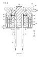
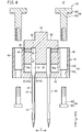
- FIG. 3A and FIG. 3B are explanatory views for explaining a process in which the holder of the sewing needle holding device in FIG. 1 holds the base end side of the sewing needle. It is explanatory drawing explaining the mode that a pressing member and a pressurization mechanism are provided in the holder of FIG. 3B. It is sectional drawing which follows the extending direction of the sewing needle of the sewing needle holding apparatus which concerns on the modification of this invention.
- the sewing needle holding device 10 As shown in FIG. 1, the sewing needle holding device 10 according to the present embodiment is used by being attached to a sewing device 12. It should be noted that in FIG. 1, the components of the sewing device 12 except a needle bar 30 and a base 32, which will be described later, are not shown. Although not shown, in the interior parts of automobiles, for example, the surface of a base material made of hard synthetic resin such as polypropylene is covered with a soft skin material, and the surface of the skin material is given a grain pattern or a stitch pattern. May enhance the aesthetic design.
- the sewing device 12 to which the sewing needle holding device 10 is attached As a suitable example of the sewing device 12 to which the sewing needle holding device 10 is attached, the above-mentioned skin material alone or a skin material integrated with a base material is a sewing object (not shown), and the sewing object is a single piece. The thing which forms the above-mentioned stitch pattern by giving chain stitch etc. is mentioned.
- the sewing needle holding device 10 is not particularly limited to this, and can be similarly applied to various sewing devices that perform sewing using the sewing needle 14.
- the sewing needle holding device 10 can hold a general sewing needle 14 that is mass-produced and distributed in the market.
- the sewing needle 14 of this type is provided with a small-diameter portion 16 on the tip side in the extending direction and a large-diameter portion 18 having a larger diameter than the small-diameter portion 16 on the base end side. Between the portion 18 and the portion 18, a tapered taper portion 20 that increases in diameter from the small diameter portion 16 toward the large diameter portion 18 is provided as the outer diameter changing portion 20a. Further, the small diameter portion 16 of the sewing needle 14 is provided with a needle hole 22 for inserting a thread.
- the sewing needle holding device 10 holds two sewing needles 14 arranged in parallel at predetermined intervals is described, but the present invention is not limited to this.
- the number of the sewing needles 14 held by the sewing needle holding device 10 may be one, or may be a plurality of three or more.
- the sewing needle holding device 10 includes a holder 24, a pressing member 26, and a pressure mechanism 28.
- the holder 24 is detachably attached to the needle bar 30 of the sewing machine 12 and is driven together with the needle bar 30 by driving the sewing machine 12 between the needle bar 30 and a base 32 facing the needle bar 30. Move up and down. Since a known configuration can be used for the attachment mechanism of the holder 24 and the needle bar 30, detailed description and illustration thereof will be omitted.
- the holder 24 holds the proximal end side of the sewing needle 14 so that the extending direction of the sewing needle 14 is along the vertical direction of the needle bar 30.
- the extending direction (the arrow X direction) of the sewing needle 14 held by the sewing needle holding device 10 is used as a reference, and the tip side of the sewing needle 14 of the sewing needle holding device 10 is also the tip side (arrow X1 side). Then, the base end side of the sewing needle 14 will be described as the base end side (arrow X2 side). In addition, the parallel direction (the arrow Y direction) of the two sewing needles 14 held by the sewing needle holding device 10 will be described as a direction orthogonal to the extending direction.
- the holder 24 has a bottomed insertion hole 36 extending from the holder front end surface 34 provided on the front end side thereof to a base end side of a predetermined length, and a direction intersecting the insertion hole 36.
- a screw hole 38 is provided that extends along the path and connects the outside of the holder 24 and the insertion hole 36.
- the large diameter portion 18 is inserted into the insertion hole 36 up to the middle thereof. At this time, it is preferable that the proximal end surface 40 of the sewing needle 14 inserted into the insertion hole 36 contacts the inner bottom surface 42 of the insertion hole 36.
- the set screw 44 By thus inserting the set screw 44 into the screw hole 38 with the large-diameter portion 18 inserted into the insertion hole 36, the thickness of the sewing needle 14 between the set screw 44 and the inner wall surface of the insertion hole 36 is increased. The diameter portion 18 is held.
- the proximal end side of the sewing needle 14 is held by the holder 24, and a part of the distal end side of the large diameter portion 18 of the sewing needle 14, the tapered portion 20, and the small diameter portion 16 are projected from the holder distal end surface 34. To do.
- the holder 24 may hold the sewing needle 14 so that at least the tapered portion 20 and the small-diameter portion 16 (the tip side from the tapered portion 20) of the sewing needle 14 project from the holder tip surface 34.
- the large-diameter portion 18 of the sewing needle 14 may have a cylindrical shape, or a notch (not shown) may be provided so that a portion of the sewing needle 14 that contacts the set screw 44 is a flat surface. Good.
- the pressing member 26 is attached to the holder 24 via a pressure mechanism 28. Specifically, the pressing member 26 is disposed along the side of both ends of the holder 24 in the orthogonal direction from the opposite portion 46 facing the holder distal end surface 34 and both ends in the orthogonal direction (arrow Y direction) of the facing portion 46. And a set of lateral portions 48 extending. Note that, for example, the distance between the surfaces 48a of the pair of side portions 48 that face each other in the orthogonal direction is set to be slightly smaller than the length of both ends of the holder 24 in the orthogonal direction, and the holder 24 is placed between these side portions 48. The holder 24 and the pressing member 26 may be engaged with each other by interposing.
- the facing portion 46 is provided with an insertion hole 50 through which the small diameter portion 16 can be inserted along the extending direction, and at least a part of the insertion hole 50 has a tapered pressure receiving surface 52 that abuts the tapered portion 20. It is provided. That is, the diameter of at least a part of the insertion hole 50 increases from the tip side (arrow X1 side) toward the base end side (arrow X2 side). The minimum diameter of the insertion hole 50 is smaller than the outer diameter of the large diameter portion 18 of the sewing needle 14. As shown in FIG. 2, the pressure receiving surface 52 may be provided so that the entire insertion hole 50 is tapered.
- Each side portion 48 is provided with a through hole 54 that penetrates the side portion 48 along the extending direction.
- the through hole 54 has a small diameter portion 54a and a large diameter portion 54b having a diameter larger than that of the small diameter portion 54a.
- the small diameter portion 54 a is provided on the tip side of the side portion 48.
- the large diameter portion 54b is provided on the base end side of the side portion 48.
- the through hole 54 may have the small diameter portion 54a and the large diameter portion 54b, and may have the same diameter in the extending direction.
- the pressurizing mechanism 28 applies a pressing force (hereinafter, also simply referred to as a pressing force) to the holder 24 and the pressing member 26 in a direction in which the holder tip surface 34 and the facing portion 46 approach each other.
- the pressure mechanism 28 has a male screw member 56 and a female screw member 58.
- the male screw member 56 has a male screw shaft portion 60 inserted through the small diameter portion 54 a of the through hole 54 from the tip side of the lateral portion 48, and a male screw head portion 62 provided integrally with the male screw shaft portion 60.
- the female screw member 58 has a hollow female screw shaft portion 64 which is inserted into the large-diameter portion 54b of the through hole 54 from the proximal end side of the side portion 48 and has therein a female screw which is screwed into the male screw shaft portion 60. , And a female screw head portion 66 provided integrally with the female screw shaft portion 64.
- the step of holding the sewing needle 14 in the sewing needle holding device 10 may be performed with or without the holder 24 attached to the needle bar 30 (see FIG. 1) of the sewing device 12. May be.
- the sewing needle 14 is inserted into the holder 24. Fix the base end.
- the needle hole 22 of the sewing needle 14 is adjusted so as to have a predetermined orientation with respect to the sewing device 12 (see FIG. 1), and the base end surface 40 of the sewing needle 14 is attached to the inner bottom surface 42 of the insertion hole 36. Abut. Further, the entire set screw 44 is inserted into the screw hole 38.
- the facing portion 46 of the pressing member 26 and the holder tip surface 34 are brought close to each other.
- the sewing needle 14 protruding from the holder front end surface 34 is inserted into the insertion hole 50 of the facing portion 46 from the front end side thereof, and the holder 24 is interposed between the side portions 48 of the pressing member 26.
- the pressure receiving surface 52 of the insertion hole 50 is brought into contact with the tapered portion 20 of the sewing needle 14.
- the male screw shaft portion 60 of the male screw member 56 is inserted from the tip side of the side portion 48 into the small diameter portion 54 a of the through hole 54, and the through hole is formed from the base end side of the side portion 48.
- the female screw shaft portion 64 of the female screw member 58 is inserted into the large diameter portion 54 b of 54. Further, the male screw shaft portion 60 is screwed into the female screw shaft portion 64, and the distance between the male screw head portion 62 and the female screw head portion 66 becomes a size capable of applying an appropriate pressing force to the holder 24 and the pressing member 26. To adjust.
- the sewing needle holding device 10 is attached to the sewing needle holding device 10 in a state in which the proximal end side is clamped from the tapered portion 20 of the sewing needle 14 between the inner bottom surface 42 of the insertion hole 36 of the holder 24 and the pressure receiving surface 52 of the pressing member 26.
- the sewing needle 14 is held.
- the needle bar 30 By driving the needle bar 30 by the sewing device 12 (see FIG. 1) to which the sewing needle holding device 10 is attached to perform sewing, although not shown, for example, two sewing objects are sewn to the sewing target.
- the needle 14 can be used to form a double stitch.
- the sewing needle 14 is liable to be sewn by friction or the like generated between the sewing object and the sewing needle 14. A force pulling in a direction of coming out of the holder 24 is likely to act.
- the force acting on the sewing needle 14 can be received by the pressure receiving surface 52 of the pressing member 26 via the tapered portion 20, so that the sewing needle 14 comes out of the holder 24 and the pressing member 26. Can be suppressed.
- the sewing needle holding device 10 for example, it is not necessary to provide a large-diameter head at the base end portion of the sewing needle 14, and it is possible to use an outer needle that is provided in a general sewing needle 14.
- the diameter changing portion 20a in other words, since the general sewing needle 14 can be used as it is, it is possible to easily prevent the sewing needle 14 from coming off at low cost.
- the outer diameter changing portion 20a is a tapered taper portion 20 whose diameter increases from the small diameter portion 16 toward the large diameter portion 18.
- the shape of the outer diameter changing portion 20a is not limited to the above tapered shape, as long as it has a portion in which the base end side is larger than the tip end side in the extending direction, for example.
- the shape of the pressure receiving surface 52 is not limited to the above-mentioned tapered shape, and may be any shape as long as it is in contact with the outer diameter changing portion 20a and can receive the above-mentioned force acting on the sewing needle 14.
- the sewing needle holding device 10 is provided with a pressurizing mechanism 28 that applies a pressing force to the holder 24 and the pressing member 26 in a direction in which the holder tip surface 34 and the facing portion 46 approach each other. did.
- the sewing needle holding device 10 can hold the sewing needle 14 better. it can. As a result, it is possible to effectively prevent the sewing needle 14 from coming off from the holder 24 and the pressing member 26.
- the pressing member 26 has the side portion 48 extending along the side of the holder 24, and the side portion 48 has the side portion 48.
- a through hole 54 penetrating along the extending direction of the sewing needle 14 is provided, the pressurizing mechanism 28 has a male screw member 56 and a female screw member 58, and the male screw member 56 has a side portion 48 in the through hole 54.
- the male screw shaft portion 60 is inserted from the front end side, and the male screw head portion 62 is provided integrally with the male screw shaft portion 60.
- the female screw member 58 is inserted into the through hole 54 from the base end side of the side portion 48.
- the pressing force can be applied to the holder 24 and the pressing member 26 with a simple configuration in which the male screw member 56 and the female screw member 58 are provided in the through hole 54 of the side portion 48. Further, by adjusting the screwing amounts of the male screw member 56 and the female screw member 58, the distance between the facing portion 46 and the holder front end surface 34 can be adjusted. This makes it possible to apply an appropriate amount of pressing force to the holder 24 and the pressing member 26 in accordance with the size of the sewing needle 14 used (for example, the length of the large diameter portion 18 in the extending direction). Therefore, the versatility of the sewing needle holding device 10 can be improved.
- the side portions 48 are set to face each other with the holder 24 sandwiched therebetween in the orthogonal direction orthogonal to the extending direction of the sewing needle 14.
- the male screw member 56 and the female screw member 58 can be provided in the through holes 54 of the side portions 48 provided on both sides of the sewing needle 14 in the orthogonal direction, respectively, the holder 24 and the pressing member 26 are further provided. It becomes possible to apply the pressing force satisfactorily.
- the holding member 26 has the side portion 48, but the present invention is not limited to this.
- a holding member 72 that does not have the side portion 48 is provided instead of the holding member 26 (see FIG. 2).
- the sewing needle holding device 70 may include a holder 74, which is longer than the holder 24 in the orthogonal direction (arrow Y direction), instead of the holder 24 (see FIG. 2 ).
- a communication hole 75 for communicating with the screw hole 38 from the outside of the holder 74 may be provided on the outer side of the screw hole 38 in the orthogonal direction because the length in the orthogonal direction increases.
- the pressing member 72 includes only the facing portion 46 facing the holder distal end surface 34, and the through holes 76 are formed on both ends of the facing portion 46 in the orthogonal direction along the extending direction. There is. Further, screw holes 78 are provided at both ends of the holder 74 in the orthogonal direction so as to be coaxially overlapped with the through holes 76 of the facing portion 46 when the facing portion 46 is opposed to the holder tip surface 34. There is.
- the pressing member 72 is attached to the holder 74 by screwing the bolt 80 as the pressing mechanism 28 into the through hole 76 and the screw hole 78 that are coaxially stacked.
- the base end side of the sewing needle 14 is held in the holder 74 in the same manner as the holder 24 (see FIG. 2) of the sewing needle holding device 10.
- the facing portion 46 is brought close to the holder front end surface 34, and the insertion hole 50 is inserted into the tapered portion 20 of the sewing needle 14.
- the pressure receiving surface 52 is brought into contact.
- the bolt 80 is screwed into the screw hole 78 and the through hole 76 that are coaxially overlapped with each other by causing the facing portion 46 to face the holder tip surface 34 as described above.
- the sewing needle holding device 70 is held by the inner bottom surface 42 of the insertion hole 36 of the holder 74 and the pressure receiving surface 52 of the pressing member 72 while the proximal end side is clamped from the tapered portion 20 of the sewing needle 14.
- the sewing needle 14 is held.
- the constituent elements such as the pressing member 72 can be simplified.
- the holders 24 and 74 extend along a bottomed insertion hole 36 into which the proximal end side of the sewing needle 14 is inserted and a direction intersecting the insertion hole 36.
- a screw hole 38 that communicates the outside of the holders 24 and 74 with the insertion hole 36 is provided, and between the set screw 44 screwed into the screw hole 38 and the inner wall surface of the insertion hole 36 of the sewing needle 14. It was decided that the base side should be held. In this case, since the sewing needle 14 is sandwiched between the set screw 44 and the inner wall surface of the insertion hole 36, it is possible to effectively prevent the sewing needle 14 from rotating inside the insertion hole 36.
- the proximal end surface 40 of the sewing needle 14 held by the holders 24 and 74 is in contact with the inner bottom surface 42 of the insertion hole 36.
- the sewing needle 14 held by the holders 24 and 74 can be prevented from moving toward the base end side in the extending direction, so that the sewing needle 14 can be held more favorably.
- the taper portion 20 of the sewing needle 14 is provided between the inner bottom surface 42 of the insertion hole 36 and the pressure receiving surface 52. It is possible to more effectively prevent the sewing needle 14 from coming off from the holders 24 and 74 and the pressing members 26 and 72 by properly sandwiching the end side.
Landscapes
- Engineering & Computer Science (AREA)
- Textile Engineering (AREA)
- Sewing Machines And Sewing (AREA)
Abstract
縫製針保持装置(10)は、延在方向の先端側から基端側に向かって、細径部(16)、外径変化部(20a)、太径部(18)が設けられた縫製針(14)の基端側を保持するホルダ(24)と、ホルダ(24)に取り付けられる押さえ部材(26)とを備える。ホルダ(24)は、ホルダ先端面(34)から、少なくとも縫製針(14)の外径変化部(20a)及び細径部(16)を突出させる。押さえ部材(26)は、ホルダ先端面(34)に対向する対向部(46)を有し、対向部(46)には、細径部(16)を挿通可能な挿通孔(50)が設けられる。挿通孔(50)の少なくとも一部には、外径変化部(20a)と当接する受圧面(52)が設けられる。
Description
本発明は、縫製針を保持する縫製針保持装置に関する。
例えば、車両の内装材として使用される表皮材等の縫製対象に対し、その意匠性を高めるべく縫製を行ってステッチを形成する場合がある。このような縫製を行う縫製装置には、縫製針を保持する縫製針保持装置が装着される。ところで、縫製時には、縫製対象と縫製針との間に生じる摩擦等に起因して、縫製針に縫製針保持装置から抜ける方向に引っ張られる力が作用することがある。そこで、縫製針保持装置として、縫製時に縫製針が抜けることを抑制するべく、例えば、特開2007-131975号公報に示される針留機構を採用することができる。
具体的には、縫製針の基端部に対し、カラーを嵌合することや、プレス成形を施すこと等により、他部位よりも大径のヘッドを形成する。また、縫製針を保持するホルダに、ヘッドより小径の挿通孔を設ける。そして、挿通孔に、縫製針のヘッドよりも先端側を挿通した状態で、ホルダに縫製針を固定する。この場合、縫製針にホルダから抜ける方向に引っ張られる力が作用しても、上記の通り、挿通孔がヘッドよりも小径であるため、ヘッドがホルダの挿通孔周縁の壁部に当接することで、ホルダからの縫製針の抜けが抑制される。
上記の針留機構では、縫製針の基端部にヘッドを形成する必要がある。すなわち、量産されて市場に流通している一般的な縫製針をそのまま使用することが困難である。このため、縫製針保持装置に縫製針を保持する工程が煩雑となったり、コストが嵩んだりする懸念がある。
本発明の主たる目的は、縫製針の抜けを容易に低コストで抑制することが可能な縫製針保持装置を提供することにある。
本発明の一態様は、延在方向の先端側に細径部が設けられ、基端側に前記細径部より大径の太径部が設けられ、前記細径部と前記太径部との間に外径変化部が設けられた縫製針を保持する縫製針保持装置であって、前記縫製針の基端側を保持するホルダと、前記ホルダに取り付けられる押さえ部材と、を備え、前記ホルダは、該ホルダのホルダ先端面から、少なくとも前記縫製針の前記外径変化部及び前記細径部を突出させ、前記押さえ部材は、前記ホルダ先端面に対向する対向部を有し、前記対向部には、前記細径部を挿通可能な挿通孔が設けられ、前記挿通孔の少なくとも一部には、前記外径変化部と当接する受圧面が設けられる。
量産されて市場に流通している一般的な縫製針は、その先端側から基端側に向かって、細径部と、外径変化部と、太径部とがこの順に設けられている。このような縫製針の基端側をホルダにより保持する。また、ホルダに取り付けられた押さえ部材に、縫製針の細径部を挿通可能な挿通孔が設けられ、該挿通孔の少なくとも一部に、縫製針の外径変化部に当接する受圧面が設けられている。
このため、縫製時に縫製針に対して、ホルダ及び押さえ部材から抜ける方向に引っ張られる力が作用しても、該力を縫製針の外径変化部を介して押さえ部材の受圧面で受けることができる。これによって、ホルダ及び押さえ部材から縫製針が抜けることを抑制できる。
つまり、本発明によれば、縫製針の基端部にヘッドを設ける必要等がなく、一般的な縫製針に備えられている外径変化部を利用すること、換言すると、一般的な縫製針をそのまま使用することができるため、縫製針の抜けを容易に低コストで抑制することが可能である。
本発明に係る縫製針保持装置について好適な実施形態を挙げ、添付の図面を参照しながら詳細に説明する。なお、以下の図において、同一又は同様の機能及び効果を奏する構成要素に対しては同一の参照符号を付し、繰り返しの説明を省略する場合がある。
図1に示すように、本実施形態に係る縫製針保持装置10は、縫製装置12に装着して用いられる。なお、図1では、縫製装置12の後述する針棒30及び基台32を除く構成要素についてはその図示を省略している。不図示ではあるが、自動車の内装部品では、例えば、ポリプロピレン等の硬質の合成樹脂等からなる基材の表面を軟質の表皮材で覆い、その表皮材の表面にシボ模様やステッチ模様を施すことによって、美観意匠性を高めることがある。縫製針保持装置10が装着される縫製装置12の好適な例として、上記のような表皮材単体、又は基材と一体化された表皮材を縫製対象(不図示)とし、該縫製対象に単環縫い等を施すことで、上記のステッチ模様を形成するものが挙げられる。しかしながら、特にこれには限定されず、縫製針保持装置10は、縫製針14を用いて縫製を行う種々の縫製装置に同様にして適用することができる。
図2及び図3Aに示すように、縫製針保持装置10は、量産されて市場に流通している一般的な縫製針14を保持することができる。この種の縫製針14は、延在方向の先端側に細径部16が設けられ、基端側に細径部16より大径の太径部18が設けられ、細径部16と太径部18との間に、細径部16から太径部18に向かうに連れて拡径するテーパ状のテーパ部20が外径変化部20aとして設けられる。また、縫製針14の細径部16には、糸を挿通するための針孔22が設けられている。
本実施形態では、縫製針保持装置10が、2本の縫製針14を所定の間隔をおいて並列させた状態で保持する例を説明するが、特にこれに限定されるものではない。縫製針保持装置10が保持する縫製針14の本数は、1本であってもよく、3本以上の複数であってもよい。
縫製針保持装置10は、ホルダ24と、押さえ部材26と、加圧機構28とを備える。図1に示すように、ホルダ24は、縫製装置12の針棒30に着脱自在に取り付けられ、該針棒30と対向する基台32との間で、縫製装置12の駆動により針棒30とともに昇降動する。なお、ホルダ24と針棒30との取り付け機構については、公知の構成を用いることができるため、その詳細な説明や図示を省略する。ホルダ24は、縫製針14の延在方向が、針棒30の昇降方向に沿うように、縫製針14の基端側を保持する。
以下では、縫製針保持装置10に保持された縫製針14の延在方向(矢印X方向)を基準とし、縫製針保持装置10についても、縫製針14の先端側を先端側(矢印X1側)とし、縫製針14の基端側を基端側(矢印X2側)として説明する。また、縫製針保持装置10に保持された2本の縫製針14の並列方向(矢印Y方向)を、延在方向の直交方向として説明する。
図2に示すように、ホルダ24には、その先端側に設けられたホルダ先端面34から所定の長さ基端側に延在する有底の挿入穴36と、該挿入穴36と交わる方向に沿って延在し、該ホルダ24の外側と前記挿入穴36とを連通するねじ孔38とが設けられる。
挿入穴36には、縫製針14の基端側として、例えば、太径部18がその中程まで挿入される。この際、挿入穴36に挿入された縫製針14の基端面40は、挿入穴36の内底面42に当接することが好ましい。このようにして太径部18を挿入穴36に挿入した状態で、ねじ孔38に止めねじ44をねじ込むことで、止めねじ44と、挿入穴36の内壁面との間に縫製針14の太径部18が狭持される。これによって、ホルダ24により縫製針14の基端側が保持され、ホルダ先端面34から、縫製針14の太径部18の先端側の一部と、テーパ部20と、細径部16とが突出する。
なお、ホルダ24は、ホルダ先端面34から、少なくとも縫製針14のテーパ部20及び細径部16(テーパ部20から先端側)が突出するよう縫製針14を保持すればよい。また、縫製針14の太径部18は円柱状であってもよいし、縫製針14の止めねじ44と当接する部分が平坦面になるように切欠き(不図示)が設けられていてもよい。
押さえ部材26は、加圧機構28を介して、ホルダ24に取り付けられている。具体的には、押さえ部材26は、ホルダ先端面34に対向する対向部46と、対向部46の直交方向(矢印Y方向)両端側から、ホルダ24の直交方向両端の側方に沿ってそれぞれ延在する一組の側方部48とを有する。なお、例えば、一組の側方部48の直交方向に対向する面48a同士の距離をホルダ24の直交方向両端の長さよりもわずかに小さくし、これらの側方部48同士の間にホルダ24を介在させることで、ホルダ24と押さえ部材26とを係合可能な構成としてもよい。
対向部46には、延在方向に沿って細径部16を挿通可能な挿通孔50が設けられ、挿通孔50の少なくとも一部には、テーパ部20と当接するテーパ状の受圧面52が設けられる。つまり、挿通孔50の少なくとも一部の径は、先端側(矢印X1側)から基端側(矢印X2側)に向かって拡径する。また、挿通孔50の最小径は、縫製針14の太径部18の外径よりも小さい。図2に示すように、挿通孔50の全体がテーパ状となるように受圧面52が設けられていてもよい。
各側方部48には、該側方部48を、延在方向に沿って貫通する貫通孔54が設けられる。貫通孔54は、小径部54aと、該小径部54aより大径の大径部54bとを有する。小径部54aは、側方部48の先端側に設けられる。大径部54bは、側方部48の基端側に設けられる。なお、貫通孔54は、小径部54a及び大径部54bを有さず、延在方向に同径であってもよい。
加圧機構28は、ホルダ24及び押さえ部材26に対し、ホルダ先端面34と対向部46とを接近させる方向に加圧力(以下、単に加圧力ともいう)を付与する。具体的には、加圧機構28は、雄ねじ部材56及び雌ねじ部材58を有する。雄ねじ部材56は、貫通孔54の小径部54aに、側方部48の先端側から挿通される雄ねじ軸部60と、該雄ねじ軸部60と一体に設けられる雄ねじ頭部62とを有する。雌ねじ部材58は、貫通孔54の大径部54bに、側方部48の基端側から挿通されるとともに内部に雄ねじ軸部60と螺合する雌ねじが形成された中空の雌ねじ軸部64と、雌ねじ軸部64と一体に設けられた雌ねじ頭部66とを有する。
貫通孔54の内部で雄ねじ軸部60を雌ねじ軸部64にねじ込む。これによって、雄ねじ頭部62と雌ねじ頭部66とが互いに接近すると、雄ねじ頭部62は対向部46の先端面に当接し、雌ねじ頭部66はホルダ24の基端側に設けられたホルダ基端面68に当接する。このため、上記のようにして、雄ねじ頭部62と雌ねじ頭部66とを接近させることにより、雄ねじ頭部62及び雌ねじ頭部66の間で、ホルダ24及び押さえ部材26に加圧力を付与することができる。
以下、縫製針保持装置10に縫製針14を保持する工程の一例について説明する。なお、縫製針保持装置10に縫製針14を保持する工程は、ホルダ24を縫製装置12の針棒30(図1参照)に装着していない状態で行ってもよいし、装着した状態で行ってもよい。
先ず、図3A及び図3Bに示すように、ホルダ24の挿入穴36に縫製針14の基端側を挿入した後、ねじ孔38に止めねじ44をねじ込むことにより、ホルダ24に縫製針14の基端側を固定する。この際、縫製針14の針孔22が、縫製装置12(図1参照)に対して所定の向きとなるように調整するとともに、挿入穴36の内底面42に縫製針14の基端面40を当接させる。また、止めねじ44の全体をねじ孔38に挿入する。
次に、図4に示すように、押さえ部材26の対向部46とホルダ先端面34とを接近させる。この際、ホルダ先端面34から突出する縫製針14を、その先端側から対向部46の挿通孔50に挿通しつつ、押さえ部材26の側方部48同士の間にホルダ24を介在させる。これによって、縫製針14のテーパ部20に挿通孔50の受圧面52を当接させる。
次に、図2に示すように、側方部48の先端側から貫通孔54の小径部54aに雄ねじ部材56の雄ねじ軸部60を挿通し、且つ側方部48の基端側から貫通孔54の大径部54bに雌ねじ部材58の雌ねじ軸部64を挿通する。さらに、雌ねじ軸部64の内部に雄ねじ軸部60をねじ込み、雄ねじ頭部62と雌ねじ頭部66との距離が、ホルダ24及び押さえ部材26に適切な加圧力を加えることが可能な大きさとなるように調整する。
これによって、ホルダ24の挿入穴36の内底面42と、押さえ部材26の受圧面52との間で、縫製針14のテーパ部20から基端側が挟持された状態で、縫製針保持装置10に縫製針14が保持される。この縫製針保持装置10が装着された縫製装置12(図1参照)により針棒30を駆動して縫製を行うことで、不図示ではあるが、例えば、縫製対象に対して、2本の縫製針14を用いてダブルステッチを形成することができる。この際、特に、上記の基材と一体化された表皮材のように、剛性等が高い縫製対象である場合、該縫製対象と縫製針14との間に生じる摩擦等によって、縫製針14にホルダ24から抜ける方向に引っ張られる力が作用し易い。
この場合であっても、縫製針14に作用する上記の力を、テーパ部20を介して押さえ部材26の受圧面52で受けることができるため、ホルダ24及び押さえ部材26から縫製針14が抜けることを抑制できる。
以上から、本実施形態に係る縫製針保持装置10によれば、例えば、縫製針14の基端部に大径のヘッドを設ける必要等がなく、一般的な縫製針14に備えられている外径変化部20aを利用すること、換言すると、一般的な縫製針14をそのまま使用することができるため、縫製針14の抜けを容易に低コストで抑制することが可能である。
上記の実施形態に係る縫製針保持装置10では、外径変化部20aは、細径部16から太径部18に向かうに連れて拡径するテーパ状のテーパ部20であることとした。しかしながら、外径変化部20aの形状は、例えば、延在方向の先端側よりも基端側が大きくなる部分を有すればよく、上記のテーパ状に限定されるものではない。また、受圧面52の形状も上記のテーパ状に限定されるものではなく、外径変化部20aと当接して縫製針14に作用する上記の力を受けることが可能な形状であればよい。
上記の実施形態に係る縫製針保持装置10では、ホルダ24及び押さえ部材26に対し、ホルダ先端面34と対向部46とを接近させる方向に加圧力を付与する加圧機構28を備える、こととした。この場合、ホルダ24と受圧面52との間に、縫製針14のテーパ部20から基端側を挟持することができるため、縫製針保持装置10により縫製針14を一層良好に保持することができる。ひいては、ホルダ24及び押さえ部材26から縫製針14が抜けることを効果的に抑制することが可能になる。
上記の実施形態に係る縫製針保持装置10では、押さえ部材26は、ホルダ24の側方に沿って延在する側方部48を有し、側方部48には、側方部48を、縫製針14の延在方向に沿って貫通する貫通孔54が設けられ、加圧機構28は、雄ねじ部材56及び雌ねじ部材58を有し、雄ねじ部材56は、貫通孔54に側方部48の先端側から挿通される雄ねじ軸部60と、雄ねじ軸部60と一体に設けられる雄ねじ頭部62と、を有し、雌ねじ部材58は、貫通孔54に側方部48の基端側から挿通されるとともに内部に雄ねじ軸部60と螺合する雌ねじが形成された中空の雌ねじ軸部64と、雌ねじ軸部64と一体に設けられた雌ねじ頭部66と、を有し、貫通孔54の内部で雄ねじ軸部60が雌ねじ軸部64にねじ込まれることで、互いに接近した雄ねじ頭部62と雌ねじ頭部66との間で、ホルダ24及び押さえ部材26に加圧力が付与されることとした。
この場合、側方部48の貫通孔54に雄ねじ部材56及び雌ねじ部材58を設ける簡単な構成によって、ホルダ24及び押さえ部材26に加圧力を付与することができる。また、雄ねじ部材56と雌ねじ部材58のねじ込み量を調整することにより、対向部46とホルダ先端面34との距離を調整することができる。これによって、使用する縫製針14の寸法(例えば、太径部18の延在方向の長さ)に応じて、適切な大きさの加圧力をホルダ24及び押さえ部材26に付与することが可能になり、縫製針保持装置10の汎用性を高めることができる。
上記の実施形態に係る縫製針保持装置10では、側方部48が、縫製針14の延在方向に直交する直交方向にホルダ24を挟んで対向する一組からなることとした。この場合、縫製針14の直交方向の両側にそれぞれ設けられた側方部48の貫通孔54に対して、雄ねじ部材56及び雌ねじ部材58を設けることができるため、ホルダ24及び押さえ部材26に一層良好に加圧力を付与することが可能になる。
なお、上記の実施形態では、押さえ部材26が側方部48を有することとしたが、特にこれに限定されるものではない。例えば、図5に示す変形例に係る縫製針保持装置70のように、押さえ部材26(図2参照)に代えて、側方部48(図2参照)を有していない押さえ部材72を備えていてもよい。また、この場合、縫製針保持装置70は、ホルダ24(図2参照)に代えて、該ホルダ24よりも直交方向(矢印Y方向)の長さが大きいホルダ74を備えていてもよい。なお、ホルダ74では、直交方向の長さが大きくなる分、ねじ孔38の直交方向の外側に、ホルダ74の外部からねじ孔38に連絡するための連絡孔75が設けられていてもよい。
具体的には、押さえ部材72は、ホルダ先端面34に対向する対向部46のみからなり、該対向部46の直交方向の両端側には、延在方向に沿って貫通孔76が形成されている。また、ホルダ74の直交方向の両端側には、ホルダ先端面34に対向部46を対向させた際に、該対向部46の貫通孔76と同軸に重なる位置に、ねじ穴78が設けられている。同軸に重ねられた貫通孔76及びねじ穴78に、加圧機構28としてボルト80がねじ込まれることで、ホルダ74に対して押さえ部材72が取り付けられる。
従って、縫製針保持装置70により縫製針14を保持する場合、先ず、縫製針保持装置10のホルダ24(図2参照)と同様にして、ホルダ74に縫製針14の基端側を保持する。次に、ホルダ74から突出する縫製針14を対向部46の挿通孔50に挿通しつつ、該対向部46をホルダ先端面34に接近させて、縫製針14のテーパ部20に挿通孔50の受圧面52を当接させる。
次に、上記のようにホルダ先端面34に対向部46を対向させることで、互いに同軸に重なったねじ穴78及び貫通孔76にボルト80をねじ込む。これによって、ホルダ74の挿入穴36の内底面42と、押さえ部材72の受圧面52との間で、縫製針14のテーパ部20から基端側が挟持された状態で、縫製針保持装置70に縫製針14が保持される。この縫製針保持装置70では、押さえ部材72等の構成要素を簡素化することができる。
上記の実施形態に係る縫製針保持装置10、70では、ホルダ24、74は、縫製針14の基端側が挿入される有底の挿入穴36と、挿入穴36と交わる方向に沿って延在し、ホルダ24、74の外側と挿入穴36とを連通するねじ孔38とが設けられ、ねじ孔38にねじ込まれた止めねじ44と、挿入穴36の内壁面との間に縫製針14の基端側が狭持されることとした。この場合、止めねじ44と挿入穴36の内壁面との間に縫製針14が狭持されるため、縫製針14が挿入穴36の内部で回転することを効果的に抑制できる。
上記の実施形態に係る縫製針保持装置10、70では、ホルダ24、74に保持された縫製針14の基端面40は、挿入穴36の内底面42に当接することとした。この場合、ホルダ24、74に保持された縫製針14が、延在方向の基端側に向かって移動することを回避できるため、縫製針14を一層良好に保持することが可能になる。また、加圧機構28によりホルダ24、74及び押さえ部材26、72に加圧力を付与する場合、挿入穴36の内底面42と受圧面52との間に、縫製針14のテーパ部20から基端側を良好に挟持して、ホルダ24、74及び押さえ部材26、72から縫製針14が抜けることを一層効果的に抑制できる。
本発明は、上記した実施形態に特に限定されるものではなく、その要旨を逸脱しない範囲で種々の変形が可能である。
10、70…縫製針保持装置 14…縫製針
16…細径部 18…太径部
20…テーパ部 20a…外径変化部
24、74…ホルダ 26、72…押さえ部材
28…加圧機構 34…ホルダ先端面
36…挿入穴 38…ねじ孔
40…基端面 42…内底面
44…止めねじ 46…対向部
48…側方部 50…挿通孔
52…受圧面 54、76…貫通孔
56…雄ねじ部材 58…雌ねじ部材
60…雄ねじ軸部 62…雄ねじ頭部
64…雌ねじ軸部 66…雌ねじ頭部
80…ボルト
16…細径部 18…太径部
20…テーパ部 20a…外径変化部
24、74…ホルダ 26、72…押さえ部材
28…加圧機構 34…ホルダ先端面
36…挿入穴 38…ねじ孔
40…基端面 42…内底面
44…止めねじ 46…対向部
48…側方部 50…挿通孔
52…受圧面 54、76…貫通孔
56…雄ねじ部材 58…雌ねじ部材
60…雄ねじ軸部 62…雄ねじ頭部
64…雌ねじ軸部 66…雌ねじ頭部
80…ボルト
Claims (7)
- 延在方向の先端側に細径部(16)が設けられ、基端側に前記細径部より大径の太径部(18)が設けられ、前記細径部と前記太径部との間に外径変化部(20a)が設けられた縫製針(14)を保持する縫製針保持装置(10、70)であって、
前記縫製針の基端側を保持するホルダ(24、74)と、前記ホルダに取り付けられる押さえ部材(26、72)と、を備え、
前記ホルダは、該ホルダのホルダ先端面(34)から、少なくとも前記縫製針の前記外径変化部及び前記細径部を突出させ、
前記押さえ部材は、前記ホルダ先端面に対向する対向部(46)を有し、前記対向部には、前記細径部を挿通可能な挿通孔(50)が設けられ、前記挿通孔の少なくとも一部には、前記外径変化部と当接する受圧面(52)が設けられる、縫製針保持装置。 - 請求項1記載の縫製針保持装置において、
前記外径変化部は、前記細径部から前記太径部に向かうに連れて拡径するテーパ状のテーパ部(20)である、縫製針保持装置。 - 請求項1又は2記載の縫製針保持装置において、
前記ホルダ及び前記押さえ部材に対し、前記ホルダ先端面と前記対向部とを接近させる方向に加圧力を付与する加圧機構(28)を備える、縫製針保持装置。 - 請求項3記載の縫製針保持装置(10)において、
前記押さえ部材(26)は、前記ホルダ(24)の側方に沿って延在する側方部(48)を有し、
前記側方部には、該側方部を、前記縫製針の延在方向に沿って貫通する貫通孔(54)が設けられ、
前記加圧機構は、雄ねじ部材(56)及び雌ねじ部材(58)を有し、
前記雄ねじ部材は、前記貫通孔に前記側方部の先端側から挿通される雄ねじ軸部(60)と、該雄ねじ軸部と一体に設けられる雄ねじ頭部(62)と、を有し、
前記雌ねじ部材は、前記貫通孔に前記側方部の基端側から挿通されるとともに内部に前記雄ねじ軸部と螺合する雌ねじが形成された中空の雌ねじ軸部(64)と、前記雌ねじ軸部と一体に設けられた雌ねじ頭部(66)と、を有し、
前記貫通孔の内部で前記雄ねじ軸部が前記雌ねじ軸部にねじ込まれることで、互いに接近した前記雄ねじ頭部と前記雌ねじ頭部との間で、前記ホルダ及び前記押さえ部材に前記加圧力が付与される、縫製針保持装置。 - 請求項4記載の縫製針保持装置において、
前記側方部は、前記縫製針の延在方向に直交する直交方向に前記ホルダを挟んで対向する一組からなる、縫製針保持装置。 - 請求項1~5の何れか1項に記載の縫製針保持装置において、
前記ホルダは、前記縫製針の基端側が挿入される有底の挿入穴(36)と、該挿入穴と交わる方向に沿って延在し、該ホルダの外側と前記挿入穴とを連通するねじ孔(38)とが設けられ、
前記ねじ孔にねじ込まれた止めねじ(44)と、前記挿入穴の内壁面との間に前記縫製針の基端側が狭持される、縫製針保持装置。 - 請求項6記載の縫製針保持装置において、
前記ホルダに保持された前記縫製針の基端面(40)は、前記挿入穴の内底面(42)に当接する、縫製針保持装置。
Priority Applications (3)
| Application Number | Priority Date | Filing Date | Title |
|---|---|---|---|
| CN201980086954.XA CN113260751A (zh) | 2018-12-28 | 2019-11-06 | 缝纫针保持装置 |
| US17/417,779 US20220074096A1 (en) | 2018-12-28 | 2019-11-06 | Sewing needle holding device |
| JP2020562885A JPWO2020137175A1 (ja) | 2018-12-28 | 2019-11-06 | 縫製針保持装置 |
Applications Claiming Priority (2)
| Application Number | Priority Date | Filing Date | Title |
|---|---|---|---|
| JP2018246533 | 2018-12-28 | ||
| JP2018-246533 | 2018-12-28 |
Publications (1)
| Publication Number | Publication Date |
|---|---|
| WO2020137175A1 true WO2020137175A1 (ja) | 2020-07-02 |
Family
ID=71126557
Family Applications (1)
| Application Number | Title | Priority Date | Filing Date |
|---|---|---|---|
| PCT/JP2019/043402 Ceased WO2020137175A1 (ja) | 2018-12-28 | 2019-11-06 | 縫製針保持装置 |
Country Status (4)
| Country | Link |
|---|---|
| US (1) | US20220074096A1 (ja) |
| JP (1) | JPWO2020137175A1 (ja) |
| CN (1) | CN113260751A (ja) |
| WO (1) | WO2020137175A1 (ja) |
Citations (8)
| Publication number | Priority date | Publication date | Assignee | Title |
|---|---|---|---|---|
| JPS367927B1 (ja) * | 1959-01-28 | 1961-06-17 | ||
| JPS5632667U (ja) * | 1979-08-22 | 1981-03-31 | ||
| JPS6080776U (ja) * | 1983-11-05 | 1985-06-05 | アイシン精機株式会社 | ミシンの針保持装置 |
| JPS6322877U (ja) * | 1986-07-29 | 1988-02-15 | ||
| JPH0535075U (ja) * | 1991-10-23 | 1993-05-14 | ジユーキ株式会社 | ミシン針の保持具 |
| JP2002113275A (ja) * | 2000-10-04 | 2002-04-16 | Janome Sewing Mach Co Ltd | 針装着具 |
| JP2007131975A (ja) * | 2005-11-10 | 2007-05-31 | Tanaka & Co Ltd | ニードルパンチ機における針留 |
| WO2019043785A1 (ja) * | 2017-08-29 | 2019-03-07 | 株式会社鈴木製作所 | ミシン針クランプ装置 |
Family Cites Families (5)
| Publication number | Priority date | Publication date | Assignee | Title |
|---|---|---|---|---|
| JPH0956946A (ja) * | 1995-08-18 | 1997-03-04 | Singer Nikko Kk | ミシンの針止め具装置 |
| JP4079224B2 (ja) * | 2003-07-01 | 2008-04-23 | 株式会社ワコール | ミシン針取付構造 |
| CN204625989U (zh) * | 2015-04-20 | 2015-09-09 | 吴江市菀坪顺达绕线器厂 | 一种缝纫机机针连接杆 |
| CN207452422U (zh) * | 2017-09-15 | 2018-06-05 | 吴江市金明机械有限公司 | 一种新型缝纫机机针夹 |
| CN207552650U (zh) * | 2017-11-21 | 2018-06-29 | 浙江耐拓机电科技有限公司 | 一种缝纫机的针板调节结构 |
-
2019
- 2019-11-06 CN CN201980086954.XA patent/CN113260751A/zh active Pending
- 2019-11-06 US US17/417,779 patent/US20220074096A1/en not_active Abandoned
- 2019-11-06 JP JP2020562885A patent/JPWO2020137175A1/ja active Pending
- 2019-11-06 WO PCT/JP2019/043402 patent/WO2020137175A1/ja not_active Ceased
Patent Citations (8)
| Publication number | Priority date | Publication date | Assignee | Title |
|---|---|---|---|---|
| JPS367927B1 (ja) * | 1959-01-28 | 1961-06-17 | ||
| JPS5632667U (ja) * | 1979-08-22 | 1981-03-31 | ||
| JPS6080776U (ja) * | 1983-11-05 | 1985-06-05 | アイシン精機株式会社 | ミシンの針保持装置 |
| JPS6322877U (ja) * | 1986-07-29 | 1988-02-15 | ||
| JPH0535075U (ja) * | 1991-10-23 | 1993-05-14 | ジユーキ株式会社 | ミシン針の保持具 |
| JP2002113275A (ja) * | 2000-10-04 | 2002-04-16 | Janome Sewing Mach Co Ltd | 針装着具 |
| JP2007131975A (ja) * | 2005-11-10 | 2007-05-31 | Tanaka & Co Ltd | ニードルパンチ機における針留 |
| WO2019043785A1 (ja) * | 2017-08-29 | 2019-03-07 | 株式会社鈴木製作所 | ミシン針クランプ装置 |
Also Published As
| Publication number | Publication date |
|---|---|
| US20220074096A1 (en) | 2022-03-10 |
| JPWO2020137175A1 (ja) | 2021-09-30 |
| CN113260751A (zh) | 2021-08-13 |
Similar Documents
| Publication | Publication Date | Title |
|---|---|---|
| US7516841B2 (en) | Connecting fastener and fastener holder | |
| US20170266393A1 (en) | Needle attachment and detachment assist device | |
| JP2001062658A (ja) | バイス装置 | |
| WO2020137175A1 (ja) | 縫製針保持装置 | |
| KR102358516B1 (ko) | 문신기구 | |
| US9931496B2 (en) | Microneedle array and microneedle array device | |
| WO2017119156A1 (ja) | 工具着脱装置および工作機械 | |
| US9768549B1 (en) | Signal connector | |
| KR101522158B1 (ko) | 뼈 플레이트 | |
| WO2019026787A1 (ja) | カニューレ用ホルダ | |
| TWI680885B (zh) | 柔版印刷版及由版鉗所構成的柔版印刷版的挾持構造 | |
| CN109077793B (zh) | 一种可调式补引装置 | |
| JP3939089B2 (ja) | 連結ファスナー及びこれに使用する連結具 | |
| KR20200087478A (ko) | 피부 시술용 주사장치 | |
| JP2000071176A (ja) | バイス装置 | |
| JP6616228B2 (ja) | 医療用処置具把持装置 | |
| KR101756167B1 (ko) | 침 조립체, 그 침 조립체를 조립하기 위한 세팅장치 및 그 세팅장치를 이용한 침 조립체의 제조방법 | |
| KR20200032558A (ko) | 미용기 | |
| US20170081792A1 (en) | Thread inserting device | |
| US10174775B2 (en) | Fastening target member and fastening structure | |
| KR200342291Y1 (ko) | 데생용 연필 홀더 | |
| JP3655462B2 (ja) | ランジュバン型超音波振動子 | |
| CN117080152A (zh) | 一种带缓冲功能的顶针结构及固晶机 | |
| JP2001211745A (ja) | 台木と穂木とを接合するための接ぎ木用棒状部材の保持装置 | |
| CN205465332U (zh) | 一种加工转向器壳体用夹具 |
Legal Events
| Date | Code | Title | Description |
|---|---|---|---|
| 121 | Ep: the epo has been informed by wipo that ep was designated in this application |
Ref document number: 19905279 Country of ref document: EP Kind code of ref document: A1 |
|
| ENP | Entry into the national phase |
Ref document number: 2020562885 Country of ref document: JP Kind code of ref document: A |
|
| NENP | Non-entry into the national phase |
Ref country code: DE |
|
| 122 | Ep: pct application non-entry in european phase |
Ref document number: 19905279 Country of ref document: EP Kind code of ref document: A1 |