WO2020137081A1 - 自動分析装置 - Google Patents
自動分析装置 Download PDFInfo
- Publication number
- WO2020137081A1 WO2020137081A1 PCT/JP2019/039745 JP2019039745W WO2020137081A1 WO 2020137081 A1 WO2020137081 A1 WO 2020137081A1 JP 2019039745 W JP2019039745 W JP 2019039745W WO 2020137081 A1 WO2020137081 A1 WO 2020137081A1
- Authority
- WO
- WIPO (PCT)
- Prior art keywords
- temperature
- reagent
- automatic analyzer
- unit
- liquid
- Prior art date
Links
Images


Classifications
-
- G—PHYSICS
- G01—MEASURING; TESTING
- G01N—INVESTIGATING OR ANALYSING MATERIALS BY DETERMINING THEIR CHEMICAL OR PHYSICAL PROPERTIES
- G01N35/00—Automatic analysis not limited to methods or materials provided for in any single one of groups G01N1/00 - G01N33/00; Handling materials therefor
- G01N35/10—Devices for transferring samples or any liquids to, in, or from, the analysis apparatus, e.g. suction devices, injection devices
- G01N35/1002—Reagent dispensers
-
- G—PHYSICS
- G01—MEASURING; TESTING
- G01N—INVESTIGATING OR ANALYSING MATERIALS BY DETERMINING THEIR CHEMICAL OR PHYSICAL PROPERTIES
- G01N35/00—Automatic analysis not limited to methods or materials provided for in any single one of groups G01N1/00 - G01N33/00; Handling materials therefor
- G01N35/00584—Control arrangements for automatic analysers
- G01N35/00594—Quality control, including calibration or testing of components of the analyser
- G01N35/00613—Quality control
- G01N35/00663—Quality control of consumables
-
- B—PERFORMING OPERATIONS; TRANSPORTING
- B01—PHYSICAL OR CHEMICAL PROCESSES OR APPARATUS IN GENERAL
- B01L—CHEMICAL OR PHYSICAL LABORATORY APPARATUS FOR GENERAL USE
- B01L3/00—Containers or dishes for laboratory use, e.g. laboratory glassware; Droppers
- B01L3/52—Containers specially adapted for storing or dispensing a reagent
-
- B—PERFORMING OPERATIONS; TRANSPORTING
- B01—PHYSICAL OR CHEMICAL PROCESSES OR APPARATUS IN GENERAL
- B01L—CHEMICAL OR PHYSICAL LABORATORY APPARATUS FOR GENERAL USE
- B01L3/00—Containers or dishes for laboratory use, e.g. laboratory glassware; Droppers
- B01L3/56—Labware specially adapted for transferring fluids
-
- B—PERFORMING OPERATIONS; TRANSPORTING
- B01—PHYSICAL OR CHEMICAL PROCESSES OR APPARATUS IN GENERAL
- B01L—CHEMICAL OR PHYSICAL LABORATORY APPARATUS FOR GENERAL USE
- B01L7/00—Heating or cooling apparatus; Heat insulating devices
-
- B—PERFORMING OPERATIONS; TRANSPORTING
- B01—PHYSICAL OR CHEMICAL PROCESSES OR APPARATUS IN GENERAL
- B01L—CHEMICAL OR PHYSICAL LABORATORY APPARATUS FOR GENERAL USE
- B01L2200/00—Solutions for specific problems relating to chemical or physical laboratory apparatus
- B01L2200/16—Reagents, handling or storing thereof
-
- B—PERFORMING OPERATIONS; TRANSPORTING
- B01—PHYSICAL OR CHEMICAL PROCESSES OR APPARATUS IN GENERAL
- B01L—CHEMICAL OR PHYSICAL LABORATORY APPARATUS FOR GENERAL USE
- B01L2300/00—Additional constructional details
- B01L2300/06—Auxiliary integrated devices, integrated components
- B01L2300/0627—Sensor or part of a sensor is integrated
- B01L2300/0663—Whole sensors
-
- B—PERFORMING OPERATIONS; TRANSPORTING
- B01—PHYSICAL OR CHEMICAL PROCESSES OR APPARATUS IN GENERAL
- B01L—CHEMICAL OR PHYSICAL LABORATORY APPARATUS FOR GENERAL USE
- B01L2300/00—Additional constructional details
- B01L2300/18—Means for temperature control
-
- G—PHYSICS
- G01—MEASURING; TESTING
- G01N—INVESTIGATING OR ANALYSING MATERIALS BY DETERMINING THEIR CHEMICAL OR PHYSICAL PROPERTIES
- G01N35/00—Automatic analysis not limited to methods or materials provided for in any single one of groups G01N1/00 - G01N33/00; Handling materials therefor
- G01N2035/00346—Heating or cooling arrangements
- G01N2035/00425—Heating or cooling means associated with pipettes or the like, e.g. for supplying sample/reagent at given temperature
-
- G—PHYSICS
- G01—MEASURING; TESTING
- G01N—INVESTIGATING OR ANALYSING MATERIALS BY DETERMINING THEIR CHEMICAL OR PHYSICAL PROPERTIES
- G01N35/00—Automatic analysis not limited to methods or materials provided for in any single one of groups G01N1/00 - G01N33/00; Handling materials therefor
- G01N35/00584—Control arrangements for automatic analysers
- G01N35/00594—Quality control, including calibration or testing of components of the analyser
- G01N35/00613—Quality control
- G01N35/00663—Quality control of consumables
- G01N2035/00673—Quality control of consumables of reagents
Definitions
- the present invention relates to an automatic analyzer, and more particularly to an automatic analyzer that adjusts the temperature of a reagent used for analysis.
- Patent Document 1 discloses a rotating unit that accommodates and rotates a reaction container.
- the bearing is supported via a bearing, and the temperature of the fixed part of the bearing is adjusted by the temperature adjusting part to adjust the temperature of the reaction vessel via the bearing and the rotating part. It is described that the temperature of the temperature control unit can be controlled by arranging, and the temperature can be maintained at a predetermined temperature without impairing the measurement accuracy even with a simple configuration.
- An automatic analyzer is a device that dispenses a sample solution containing a substance to be analyzed and a reaction reagent into a reaction container, causes them to react, and optically measures the reaction solution for analysis.
- a specific biological component or chemical substance contained in a biological sample such as blood, serum or urine is detected.
- An object of the present invention is to provide an automatic analyzer capable of controlling the temperature of a reagent used in the device with higher accuracy than ever before.
- the present invention includes a plurality of means for solving the above problems, and one example thereof is an automatic analyzer for reacting a sample and a reagent, and measuring the reaction liquid thus reacted,
- a processing unit that performs a process before analysis, a supply device that supplies the reagent to a reaction container installed in the processing unit, and a liquid temperature adjustment that adjusts the temperature of the reagent supplied to the reaction container by the supply device.
- the temperature of the reagent used in the device can be controlled with higher accuracy than in the past.
- FIG. 3 is an enlarged view of a processing unit and a liquid temperature adjusting unit in the automatic analyzer according to the first embodiment.
- 3 is a diagram showing a structure of a liquid temperature adjusting unit of the automatic analyzer in Example 1.
- FIG. 4 is a diagram showing a structure of a liquid temperature adjusting unit of the automatic analyzer according to the first embodiment when viewed from a direction different from FIG. 3.
- 6 is a block diagram showing a method of controlling a liquid temperature adjusting unit of the automatic analyzer in Example 1.
- FIG. 5 is a diagram showing an example of a relationship between an air temperature of a first temperature detection unit and a target liquid temperature of a second temperature detection unit of the automatic analyzer according to the first embodiment.
- FIG. 7 is an enlarged view of a processing unit and a liquid temperature adjusting unit in the automatic analyzer according to the second embodiment of the present invention.
- FIG. 6 is a diagram showing a structure of a liquid temperature adjusting unit of the automatic analyzer in Example 2.
- FIG. 9 is a diagram showing the structure of the liquid temperature adjusting unit of the automatic analyzer according to the second embodiment when viewed from a direction different from FIG. 8.
- FIG. 7 is an enlarged view of a processing unit and a liquid temperature adjusting unit in the automatic analyzer according to the third embodiment of the present invention.
- FIG. 8 is a diagram showing a structure of a liquid temperature adjusting section of an automatic analyzer in Example 3.
- FIG. 12 is a diagram showing a structure of a liquid temperature adjusting unit of an automatic analyzer according to a third embodiment when viewed from a direction different from FIG. 11.
- FIG. 9 is a block diagram showing a method of controlling a liquid temperature adjusting unit of an automatic analyzer according to a third embodiment.
- FIG. 9 is a diagram showing an example of a relationship between an air temperature of a third temperature detection unit and a target liquid temperature of a fourth temperature detection unit of the automatic analyzer in Example 3. It is an enlarged view of a processing unit and a liquid temperature adjusting unit in an automatic analyzer according to a fourth embodiment of the present invention.
- FIG. 9 is a diagram showing a structure of a liquid temperature adjusting section of an automatic analyzer in Example 3.
- FIG. 12 is a diagram showing a structure of a liquid temperature adjusting unit of an automatic analyzer according to a third embodiment when viewed from
- FIG. 9 is a block diagram showing a method of controlling a liquid temperature adjusting unit of an automatic analyzer in Example 4.
- FIG. 9 is a diagram showing an example of a relationship between an estimated value of an air temperature and a calorific value change amount of a first temperature detection unit of an automatic analyzer in Example 4 and a target liquid temperature of a second temperature detection unit.
- the following example is an example when applied to an automatic immune analyzer.
- the present invention is not limited to the immuno-automatic analyzer, but can be applied to other types of auto-analyzers such as biochemical auto-analyzers that require temperature adjustment of reagents.
- it can be applied to an analysis unit or the like that analyzes electrolyte analysis items of a biochemical automatic analysis device.
- Example 1 of the automatic analyzer of the present invention will be described with reference to FIGS. 1 to 6.
- FIG. 1 is a plan view showing the overall configuration of the automatic analyzer according to the first embodiment.
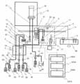
- FIG. 2 is an enlarged view of the processing section and the liquid temperature adjusting section in the automatic analyzer shown in FIG.
- the automatic analyzer 100 is a device for reacting a sample and a reagent and measuring the reacted reaction liquid, and includes a sample dispensing nozzle 303, a reaction table 60, and a reaction table 60.
- the rack transport line 317 is a line for transporting a rack 301 capable of mounting a plurality of sample containers 302 containing samples to a sample dispensing position or the like.
- the sample dispensing nozzle 303 is a nozzle for sucking the sample contained in the sample container 302 and discharging the sample into the reaction container 11.
- the reaction table 60 is a disk for carrying out the reaction between the sample and the reagent at a constant temperature, and the temperature thereof is kept at a predetermined temperature by a heater (not shown) to promote the reaction between the sample and the reagent.
- a plurality of reaction vessels 11 are held in the reaction table 60, and serve as a place where the sample and the reagent are mixed and reacted.
- the reaction container transfer mechanism 306 transfers the reaction container 11.
- the sample dispensing tip/reaction container holding member 307 stores the disposable chip used for sample dispensing and the reaction container 11.
- the reagent disc 311 is a disc for storing reagent bottles, and is kept cold in order to suppress deterioration of the reagent.
- the reagent dispensing nozzle 314 is a nozzle for sucking the reagent stored in the reagent bottle in the reagent disc 311 and discharging the reagent to the reaction container 11.
- the processing unit 3 performs processing before the analysis of the sample by the detector 16.
- the detector 16 detects using the liquid in which the reaction is completed in the reaction container 11. Details of the processing unit 3 and the detector 16 will be described later.
- the control device 319 controls various operations of each member described above, and also performs arithmetic processing for obtaining the concentration of a predetermined component in the sample from the detection result performed by the detector 16.
- the control device 319 is provided with a control unit 219 that controls the temperature of the liquid temperature adjusting unit 1. Details of the control unit 219 will also be described later.
- the user Prior to the analysis, the user installs consumables such as a reagent bottle, a sample dispensing tip, and a reaction container 11 required for the analysis on the reagent disk 311 and the sample dispensing chip/reaction container holding member 307 in the analyzer, respectively. Keep it.
- consumables such as a reagent bottle, a sample dispensing tip, and a reaction container 11 required for the analysis on the reagent disk 311 and the sample dispensing chip/reaction container holding member 307 in the analyzer, respectively. Keep it.
- the reaction container transport mechanism 306 of the analyzer transports the unused reaction container 11 and the sample dispensing tip to the reaction table 60 and the sample dispensing tip mounting position.
- the reagent dispensing nozzle 314 accesses the inside of the reagent disc 311, so that the reagent stored in the reagent bottle is dispensed into the reaction container 11 on the reaction table 60.
- the sample is dispensed into the reaction container 11 by the sample dispensing nozzle 303, and the reaction between the sample and the reagent is started.
- the reaction referred to herein means, for example, the binding of the analyte and the luminescent labeling substance by the antigen-antibody reaction using the luminescent labeled antibody that reacts only with the specific antigen of the analyte as a reagent.
- the sample and the reagent are agitated by suctioning and discharging the mixture of the sample and the reagent in the sample dispensing tip.
- the used sample dispensing tip is transported to the discarding section by the reaction container transporting mechanism 306 and discarded.
- the transport mechanism 51 transports the reaction container 11 placed on the reaction table 60 for a predetermined time to the magnetic separation unit 12 in the processing unit 3 which performs the pretreatment of the analysis.
- the magnetic separation unit 12 magnetic separation of the sample is performed, then an unnecessary solution is discharged from the suction nozzle 52, and a reagent called a replacement liquid is discharged from the discharge nozzle 53.
- the substitution liquid is stored in the reagent storage unit 30, opens the solenoid valve 34, closes the solenoid valve 35, and sucks the reagent into the syringe pump 26 that intermittently delivers the reagent, and then closes the solenoid valve 34 to close the solenoid. It is supplied by opening the valve 35 and discharging from the syringe pump 26.
- the temperature of the replacement liquid is adjusted in advance in the liquid temperature adjusting unit 1 by the method described later.
- the suction nozzle 52, the discharge nozzle 53, the reagent storage unit 30, the electromagnetic valves 34 and 35, and the syringe pump 26 correspond to a supply device that supplies a reagent to the reaction container 11 installed in the processing unit 3.
- the transport mechanism 51 transports the reaction container 11 to the stirring unit 13 in the processing unit 3.
- the stirring is performed by rotating the reaction container 11 with the motor 14.
- the transport mechanism 51 transports the reaction container 11 to the reaction table 60 again.
- reaction container 11 placed on the reaction table 60 after a predetermined time has been transferred to the container holder 22 by the transfer mechanism 51, and the reaction liquid is guided to the detection container 15 from the suction nozzle 21. Get burned.
- a signal from the reaction solution is detected by the detector 16 in the detection container 15, and the analysis result is notified to the user and recorded in the storage device.
- reaction container 11 is transferred to the discarding unit by the transfer mechanism 51 and the reaction container transfer mechanism 306, and is discarded.
- the temperature adjustment of the replacement liquid by the liquid temperature adjustment unit 1 described below is preferably started at the time of warming up the automatic analyzer 100 and stably executed at the time of standby.
- the timing is not particularly limited to this timing, and it is desirable that the temperature is stably adjusted during the analysis.
- a first temperature detection unit 4 that detects the temperature of the air in the processing unit 3 is provided near the magnetic separation unit 12 and the stirring unit 13 in the processing unit 3.
- the liquid temperature adjusting unit 1 for adjusting the temperature of the replacement liquid measures the liquid temperature at the outlet of the spiral pipe 110 (see FIG. 3, etc.) in order to detect the temperature of the reagent supplied to the processing unit 3.
- the second temperature detector 5 is provided.
- the first temperature detection unit 4 and the second temperature detection unit 5 are composed of a thermistor, a thermocouple, etc., and the detection signal is taken in by the sensor input processing unit 202 of the control unit 201.
- the signals from the first temperature detection unit 4 and the second temperature detection unit 5 are taken into the sensor input processing unit 202 of the control unit 201, and the target temperature calculation unit 203 calculates the target liquid temperature of the second temperature detection unit 5,
- the Peltier element control unit 204 controls energization of the Peltier element.
- the control unit 201 obtains the target value of the second temperature to be detected by the second temperature detection unit 5 based on the first temperature detected by the first temperature detection unit 4, and the actually measured second temperature and target value.
- the liquid temperature adjusting unit 1 executes the temperature control of the replacement liquid based on the control signal.
- control unit 201 performs temperature adjustment such that the higher the first temperature is, the lower the second temperature is, and the lower the first temperature is, the higher the second temperature is.
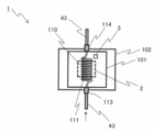
- the liquid temperature adjusting unit 1 includes a metal block 101, a spiral pipe 110, connectors 113 and 114, thermal interfaces 104, 105 and 106, a heat diffusion plate 103, a first Peltier element 2, and fins. It is composed of a base 107, fins 108, and a heat insulating material 102.
- the metal block 101 is a metal block made of a metal having a high thermal conductivity such as aluminum, and a spiral pipe 110 formed by spirally forming a pipe of stainless steel or the like is attached.
- a method of mounting the spiral pipe 110 there is a method of forming a through hole in the metal block 101, inserting the spiral pipe 110, and pouring solder or the like into the periphery to fix the spiral pipe 110.
- Connectors 113 and 114 are attached to the inlet and outlet of the spiral pipe 110.
- the connectors 113 and 114 are threaded and are connected to a tube 43 for supplying the replacement liquid from the reagent storage unit 30 to the discharge nozzle 53 by a tube joint. It is not necessary to use the spiral pipe 110, and a pipe having another shape such as a straight line may be used.
- a heat diffusion plate 103 made of aluminum or the like is connected to the metal block 101 described above via a thermal interface 104 such as grease. Further, the first Peltier element 2 is connected to the surface of the metal block 101 different from the surface connected to the heat diffusion plate 103 via the thermal interface 105. Further, a heat sink composed of a fin base 107 and a fin 108 is connected to the surface on the opposite side of the first Peltier element 2 via a thermal interface 106.
- the first Peltier element 2, the thermal interfaces 104, 105 and 106, and the heat diffusion plate 103 are fixed by a method such as sandwiching them between the metal block 101 and the fin base 107 and fixing them with screws.
- the periphery of the metal block 101 is insulated by the heat insulating material 102.
- thermal interfaces 104, 105 and 106 are all thermal grease.
- the first Peltier element 2 is energized so that the surface on the metal block 101 side has a low temperature and the surface on the fin base 107 side has a high temperature.
- the heat of the reagent moving in the spiral pipe 110 or the heat of the reagent staying in the spiral pipe 110 passes through the metal block 101, the grease 104, the heat diffusion plate 103, and the grease 105 to reach the first Peltier element 2. It is absorbed. Further, the surface on the opposite side of the first Peltier element 2 generates heat (radiates heat), the heat is transmitted from the grease 106 and the fin base 107 to the fins 108, and is radiated to the air flowing between the fins 108 by the fan 109.
- the temperature of the fins 108 is lower than the air temperature, heat is taken from the air flowing between the fins by the fan 109, passes through the fin base 107 and the grease 106, and is absorbed by the first Peltier element 2.
- the surface on the opposite side of the first Peltier element 2 generates heat (radiates heat), and the heat passes through the grease 105, the heat diffusion plate 103, the grease 104, and the metal block 101, and the reagent moving in the spiral pipe 110, Alternatively, it is given to the reagent retained therein.
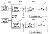
- Figure 5 shows a block diagram of Peltier element control.
- the target temperature calculation unit 203 of the control unit 201 calculates the target temperature 205 to be detected by the second temperature detection unit 5 from the air temperature near the processing unit 3 detected by the first temperature detection unit 4.
- the Peltier element control unit 204 based on the difference between the target temperature of the second temperature detection unit 5 calculated by the target temperature calculation unit 203 and the temperature of the reagent actually detected by the second temperature detection unit 5, the first Peltier device A current value to be output to the element 2 is calculated, and a command signal is output to the first Peltier element 2 so that the calculated current value flows.
- a proportional-integral-derivative control is performed at a constant time interval to turn on/off the current. That is, the duty is controlled to control the cooling or heating capacity of the first Peltier element 2. At this time, the current during energization is constant.
- the current flowing through the first Peltier element 2 is changed to control the cooling and heating capabilities of the Peltier element.
- the first Peltier element 2 is continuously energized.
- FIG. 6 shows an example of the relationship between the air temperature detected by the first temperature detection unit 4 and the target liquid temperature of the second temperature detection unit 5.
- the target temperature of the second temperature detection unit 5, that is, the liquid temperature of the reagent (substitution liquid) is set to be lower as the air temperature near the processing unit 3 detected by the first temperature detection unit 4 is higher.
- the automatic analyzer 100 includes a processing unit 3 that performs a process before analysis of a sample, a supply device that supplies a reagent to a reaction container 11 installed in the processing unit 3, and a supply device.
- a first temperature detection unit 4 that detects the temperature of the liquid temperature adjustment unit 1 and the control unit 201 perform the temperature adjustment of the reagent based on the first temperature detected by the first temperature detection unit 4. .
- the temperature of the reagent in the magnetic separation unit 12 and the stirring unit 13 can be maintained within a certain temperature range, so that the reaction between the sample and the reagent is performed under more appropriate conditions, and the analysis accuracy of the detector 16 is improved.
- the liquid temperature adjusting unit 1 and the control unit 201 are arranged in the liquid temperature adjusting unit 1 and further include a second temperature detecting unit 5 for detecting the temperature of the reagent supplied to the processing unit 3.
- the target value of the second temperature detected by the second temperature detection unit 5 is obtained based on the above, and the temperature is adjusted based on the difference between the second temperature and the target value.
- the temperature of the reagent in the part 13 can be kept within a certain temperature range.
- liquid temperature adjusting unit 1 and the control unit 201 perform the temperature adjustment such that the second temperature is lower as the first temperature is higher and the second temperature is higher as the first temperature is lower, so that the liquid temperature adjusting unit 1 and the control unit 201 are more accurate. It is possible to keep the temperature of the reagent in the magnetic separation unit 12 and the stirring unit 13 within a certain temperature range.
- the processing section 3 can process the reaction solution which is a position that greatly contributes to the improvement of the analysis accuracy. By making it the part to be performed, it is possible to further contribute to the improvement of the analysis accuracy.
- the control unit 201 may use the average value of both, or may use one of them with weighting.
- FIG. 7 is an enlarged view of the processing unit and the liquid temperature adjusting unit in the automatic analyzer according to the second embodiment.
- FIG. 8 is a diagram showing the structure of the processing unit of the automatic analyzer according to the second embodiment, and
- FIG. 9 is a diagram showing the structure of the liquid temperature adjusting unit when viewed from a direction different from that in FIG.
- a reagent container 9 for containing a reaction auxiliary liquid which is a reagent to be supplied to the detection container 15, and a reagent for containing a cleaning liquid are added to the container holding portion 22.
- the container 10 is installed.
- the reagent (reaction auxiliary liquid) in the reagent container 9 is supplied from the reagent storage unit 31 by operating the syringe pump 27 and the electromagnetic valves 36 and 37.
- the reagent (cleaning liquid) in the reagent container 10 is supplied from the reagent storage unit 32 by operating the syringe pump 28 and the electromagnetic valves 38 and 39.
- the container holder 22 can rotate and move up and down.
- the container holder 22 For the reagents in the reagent containers 9 and 10 and the solution in the reaction container 11, the container holder 22 is rotated and moved up and down to bring the tip of the suction nozzle 21 into the required container, and the syringe pump 29 and the solenoid valve 40, It is guided to the detection container 15 by operating 41. In the detection container 15, the detector 16 detects a signal from the reaction liquid, and then the reaction liquid and the reagent are discharged to the waste liquid container 42.
- the operation of the container holding unit 22 and the operations of the syringe pumps 27, 28 and the solenoid valves 36, 37, 38, 39 are executed according to a determined sequence.
- the metal block 101A of aluminum or the like has the same shape as the spiral pipe 110.
- Connectors 113, 114, 115, 116, 117 and 118 are attached to the inlets and outlets of the spiral pipes 110, 111 and 112, respectively.
- the connectors 113, 114, 115, 116, 117, 118 are threaded to connect the tube 43 by means of a tube joint.
- control unit 201A controls the temperature adjustment by the liquid temperature adjusting unit 1A so that the temperature of the reagent supplied to the reagent containers 9 and 10 is also adjusted based on the first temperature.
- the configurations and operations of the sensor input processing unit 202A, the target temperature calculation unit 203A, and the Peltier element control unit 204A are the same as those of the sensor input processing unit 202, the target temperature calculation unit 203, and the Peltier element control unit 204, respectively.
- reagent containers 9 and 10 for temporarily holding the reagent supplied to the detection container 15 for analyzing the sample
- a container holding portion 22 for holding the reaction container 11 and the reagent containers 9 and 10.
- the liquid temperature adjusting unit 1A and the control unit 201A also adjust the temperature of the reagent supplied to the reagent containers 9 and 10 based on the first temperature, so that the reagent containers 9 and 10 that are closer to the detector 16 are located. Since the temperature of the reagent supplied to the detection container 15 via the above can also be adjusted, the analysis accuracy in the detector 16 can be further improved.
- FIG. 10 is an enlarged view of the processing unit and the liquid temperature adjusting unit in the automatic analyzer according to the third embodiment.
- FIG. 11 is a diagram showing the structure of the liquid temperature adjusting unit of the automatic analyzer according to the third embodiment
- FIG. 12 is a diagram showing the structure when viewed from a direction different from FIG.
- FIG. 13 is a block diagram showing a method of controlling the liquid temperature adjusting unit of the automatic analyzer according to the third embodiment.
- FIG. 14 is a diagram illustrating an example of the relationship between the air temperature of the third temperature detection unit and the target liquid temperature of the fourth temperature detection unit of the automatic analyzer according to the third embodiment.
- a third temperature detecting unit 7 for detecting the air temperature around the container holding unit 22 is further provided.
- the liquid temperature adjustment unit 1B that adjusts the temperature of the replacement liquid and the reagent of this embodiment is supplied to the reagent containers 9 and 10.
- a fourth temperature detection unit 8 that detects the temperature of the reagent is provided.
- the signals from the first temperature detection unit 4, the second temperature detection unit 5, the third temperature detection unit 7, and the fourth temperature detection unit 8 are fetched by the sensor input processing unit 202B of the control unit 201B.
- the liquid temperature adjusting unit 1B of the present embodiment in addition to the heat diffusion plate 103, the first Peltier element 2, the heat sink including the fin base 107 and the fin 108, the metal block 101B is provided.
- the second Peltier element 6 is connected via the thermal interface 105.
- a fourth temperature detection unit 8 including a thermistor and a thermocouple is provided near the outlets of the spiral pipes 111 and 112. The signal from the fourth temperature detection unit 8 is captured by the sensor input processing unit 202B of the control unit 201B.
- first Peltier element 2 and the second Peltier element 6 are provided in the same metal block 101B
- first Peltier element 2 and the second Peltier element 6 can be provided in separate metal blocks.
- a heat insulating material or the like can be used between them.
- the target temperature calculation unit 203B calculates the target temperature 207B of the reagent solution to be detected by the fourth temperature detection unit from the air temperature near the container holding unit 22 detected by the third temperature detection unit 7.
- the first Peltier element control unit 204B based on the target temperature of the second temperature detection unit 5 calculated by the target temperature calculation unit 203B and the actual temperature detected by the second temperature detection unit 5, the first Peltier element control unit 204B.
- the duty of the current output to 2 is controlled.
- the second Peltier element control unit 206B based on the target temperature of the fourth temperature detection unit calculated by the target temperature calculation unit 203B and the actual temperature detected by the fourth temperature detection unit 8, the second Peltier element 6 Controls the duty of the current output to.
- the target liquid temperature of the second temperature detection unit 5 obtained by the target temperature calculation unit 203B As shown in FIG. 6, the higher the air temperature near the processing unit 3 detected by the first temperature detection unit 4, the second The target temperature of the temperature detection unit 5, that is, the temperature of the reagent (substitution liquid) is set to be low.
- a third temperature detecting unit 7 for detecting at least one of the temperature of the air around the container holding unit 22 and the temperature of the reagent in the reagent containers 9 and 10 is further provided, and the liquid temperature adjusting unit 1B is controlled.
- the unit 201B adjusts the temperature of the reagent supplied to the reagent containers 9 and 10 on the basis of the third temperature detected by the third temperature detection unit 7 so that the detection container 15 passes through the reagent containers 9 and 10.
- the temperature of the supplied reagent can be adjusted, and the analysis accuracy can be further improved as compared with the second embodiment.
- the liquid temperature adjusting unit 1B and the control unit 201B further include a fourth temperature detecting unit 8 that detects the temperature of the reagent supplied to the reagent containers 9 and 10, and the liquid temperature adjusting unit 1B and the control unit 201B A target value of the fourth temperature detected by the fourth temperature detection unit 8 is obtained based on the three temperatures, and temperature adjustment is executed based on the difference between the fourth temperature and the target value.
- the liquid temperature adjustment unit 1B, control The unit 201B performs temperature adjustment such that the fourth temperature is lower as the third temperature is higher and the fourth temperature is higher as the third temperature is lower, and thus the detection is performed with higher accuracy via the reagent containers 9 and 10.
- the temperature of the reagent supplied to the container 15 can be adjusted.
- the first temperature detection unit 4 detects the temperature of the air in the vicinity of the processing unit 3, but instead or in addition, the temperature of the reagent in the reaction container 11 can be detected.
- the third temperature detection unit 7 has described the case of detecting the air temperature in the vicinity of the container holding unit 22, instead of or in addition to detecting the liquid temperature in the reagent container 9 and/or the reagent container 10. You can
- FIG. 15 is an enlarged view of the processing unit and the liquid temperature adjusting unit in the automatic analyzer according to the fourth embodiment.
- FIG. 16 is a block diagram showing a method of controlling the liquid temperature adjusting unit of the automatic analyzer according to the fourth embodiment.
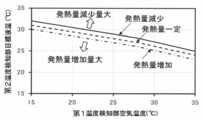
- FIG. 17 is a diagram showing an example of the relationship between the estimated values of the air temperature and the calorific value change amount of the first temperature detection unit and the target liquid temperature of the second temperature detection unit of the automatic analyzer according to the fourth embodiment.
- the detection units 70 and 71 of the motors and solenoids provided in the transport mechanism 51 and the detection unit 72 of the motor 14 that rotationally drives the stirring unit 13 are provided, and the current flowing through the motors and the like is provided.
- the detection units 70, 71, 72 may detect voltage or both current and voltage.
- control unit 201C is provided with a second sensor input processing unit 209C, a heat generation amount estimation unit 210C, and a heat generation amount change amount calculation unit 211C.
- the heat generation amount estimation unit 210C estimates the heat generation amount based on the current of the motor or the like detected by the detection units 70, 71, 72.
- the calorific value change amount calculation unit 211C calculates the change amount of the calorific value.
- the second temperature is calculated based on the air temperature in the vicinity of the processing unit 3 detected by the first temperature detection unit 4 and the change amount of the heat generation amount calculated by the heat generation amount change amount calculation unit 211C.
- the target temperature 205C in the temperature detector 5 is calculated.
- the Peltier device control unit 204C controls the duty of the current output to the first Peltier device 2 based on the target temperature 205C of the second temperature detection unit 5 and the temperature actually detected by the second temperature detection unit 5. ..
- FIG. 17 shows the relationship between the temperature detected by the first temperature detection unit 4 and the target liquid temperature of the second temperature detection unit 5 using the amount of change in the amount of heat generation calculated by the amount of heat generation change calculation unit 211C as a parameter. An example is shown.
- the target temperature of the second temperature detecting unit 5 that is, the temperature of the reagent (substitution liquid) is lower.
- the target liquid temperature of the second temperature detection unit 5 is set to be lower as the amount of increase of the heat generation amount is larger, and the target liquid temperature of the second temperature detection unit 5 is set to be higher as the amount of decrease of the heat generation amount is larger. I have to.
- the liquid temperature adjusting unit 1 and the control unit 201C further include an estimation unit that estimates the heat generation amount of the heating element existing in the automatic analyzer 100, and the liquid temperature adjustment unit 1 and the control unit 201C include the heat generation amount estimated by the estimation unit in addition to the first temperature.
- a target value of the second temperature detected by the second temperature detection unit 5 is obtained based on the amount of change, and temperature adjustment is executed based on the difference between the second temperature and the target value.
- the unit 201C adjusts the temperature so that the second temperature is lower as the amount of increase of the calorific value is larger, and the second temperature is higher as the amount of increase of the calorific value is smaller, thereby responding to the fluctuation of the calorific value.
- the cooling capacity of the first Peltier element 2 is adjusted, the temperature of the reagent in the magnetic separation section 12 and the stirring section 13 can be maintained in a certain temperature range with higher accuracy. Therefore, the reaction between the sample and the reagent can be performed under more appropriate conditions, and the analysis accuracy in the detector 16 can be further improved.
- the estimation of the heat generation amount as in the present embodiment can be performed by the liquid temperature adjusting unit 1A of the second embodiment and the liquid temperature adjusting unit 1B of the third embodiment.
- the target value of the second temperature detected by the second temperature detection unit 5 is calculated based on the amount of change in the calorific value estimated by the estimation unit, and the difference between the second temperature and the target value is calculated.
- the liquid temperature adjusting unit 1 and the control unit 201C are not limited to the case where the temperature adjustment is performed based on the temperature change based on the change amount of the calorific value estimated by the estimating unit, in addition to the third temperature described in the third embodiment.
- the target value of the fourth temperature described in the third embodiment is obtained, and the temperature adjustment is performed based on the difference between the fourth temperature and the target value.
- the temperature adjustment can be executed so that the fourth temperature becomes higher as the increase amount of is smaller.
- the temperature of the reagent supplied to the detection container 15 via the reagent containers 9 and 10 can be adjusted with higher accuracy, and the analysis accuracy in the detector 16 can be further improved.
- the present invention is not limited to the above-described embodiments, but includes various modifications.
- the above embodiments have been described in detail for the purpose of explaining the present invention in an easy-to-understand manner, and are not necessarily limited to those having all the configurations described.
- Liquid temperature adjusting unit liquid temperature adjusting device 2... 1st Peltier element 3... processing part 4... 1st temperature detection part 5... 2nd temperature detection part 6... 2nd Peltier element 7... 3rd temperature detection part 8... 4th temperature detection part 9, 10... Reagent container 11... Reaction container 12... Magnetic separation part 13... Stirring part 14... Motor (heating element) 15... Detection container 16... Detector 21... Suction nozzle 22... Container holding parts 26, 27, 28, 29... Syringe pump (supply device) 30, 31, 32... Reagent storage unit (supply device) 34, 35, 36, 37, 38, 39, 40, 41... Solenoid valve (supply device) 42... Waste container 43... Tube 51...
Landscapes
- Health & Medical Sciences (AREA)
- Chemical & Material Sciences (AREA)
- Clinical Laboratory Science (AREA)
- Chemical Kinetics & Catalysis (AREA)
- Quality & Reliability (AREA)
- Engineering & Computer Science (AREA)
- Life Sciences & Earth Sciences (AREA)
- Biochemistry (AREA)
- General Health & Medical Sciences (AREA)
- General Physics & Mathematics (AREA)
- Immunology (AREA)
- Pathology (AREA)
- Analytical Chemistry (AREA)
- Physics & Mathematics (AREA)
- Medicinal Chemistry (AREA)
- Automatic Analysis And Handling Materials Therefor (AREA)
Abstract
検体の分析前の処理を行う処理部3と、処理部3に設置された反応容器11へ試薬を供給される供給機器と、供給機器によって反応容器11に供給される試薬の温度を調整する液温調整部1,制御部201と、処理部3内の空気の温度、反応容器11に供給された試薬の温度のうち少なくともいずれか一方の温度を検知する第1温度検知部4と、を備え、液温調整部1,制御部201は、第1温度検知部4で検知される第1温度に基づいて試薬の温度調整を実行する。
Description
本発明は、自動分析装置に関し、特に分析に用いられる試薬の温度を調整する自動分析装置に関する。
簡単な構成でありながら、測定精度を損なうことなく所定の温度に保持可能な反応容器撹拌部を備えた自動分析装置の一例として、特許文献1には、反応容器を収容し回転する回転部を、軸受を介して支持し、この軸受の固定部を温度調整部により温度調整することにより、軸受および回転部を介して、反応容器の温度を調整し、固定部である温度調節部に温度センサを配置して、温度調節部の温度を可能であり、簡単な構成でありながら、測定精度を損なうことなく所定の温度に保持可能となる、ことが記載されている。
自動分析装置は、分析対象物質の含まれる検体溶液と反応試薬とを反応容器に分注して反応させ、反応液を光学的に測定することによって分析を行う装置である。このような自動分析装置では、例えば、血液、血清、尿等の生体試料中に含まれる特定の生体成分や化学物質等を検出している。
自動分析装置において十分な分析精度を得るためには、検体の前処理や分析に使われる試薬の温度を一定に保つ必要がある。
試薬の温度を調整する方法としては、特許文献1のように、反応容器撹拌機構において、反応容器を設置した回転部の軸受をペルチェ素子等の温度調整部に接続する方法が知られている。
しかしながら、この特許文献1に記載された方法の場合、温度調整部と試薬の間には軸受や容器を介在させている。このため、試薬の温度を正確に制御する方法をより簡易にする余地があり、温度制御の精度を改善する余地があった。
本発明の目的は、装置で使われる試薬の温度を従来に比べて高い精度で制御することが可能な自動分析装置を提供することにある。
本発明は、上記課題を解決する手段を複数含んでいるが、その一例を挙げるならば、検体と試薬を反応させ、この反応させた反応液を測定する自動分析装置であって、前記検体の分析前の処理を行う処理部と、前記処理部に設置された反応容器へ前記試薬を供給される供給機器と、前記供給機器によって反応容器に供給される前記試薬の温度を調整する液温調整装置と、前記処理部内の空気の温度、前記反応容器に供給された前記試薬の温度のうち少なくともいずれか一方の温度を検知する第1温度検知部と、を備え、前記液温調整装置は、前記第1温度検知部で検知される第1温度に基づいて前記試薬の温度調整を実行することを特徴とする。
本発明によれば、装置で使われる試薬の温度を従来に比べて高い精度で制御することができる。上記した以外の課題、構成および効果は、以下の実施例の説明により明らかにされる。
以下、本発明の自動分析装置の実施例について添付図面を参照して説明する。
以下の例は、免疫自動分析装置に適用した場合の例である。なお、本発明は免疫自動分析装置に限られず、生化学自動分析装置などの試薬の温度調整が必要な他の型の自動分析装置にも適用することができる。例えば生化学自動分析装置の電解質分析項目を分析する分析部などに適用することができる。
<実施例1>
本発明の自動分析装置の実施例1について図1乃至図6を用いて説明する。
本発明の自動分析装置の実施例1について図1乃至図6を用いて説明する。
まず、図1および図2を用いて、本実施例における自動分析装置の全体構成について概略を説明する。図1は、本実施例1の自動分析装置の全体構成を表した平面図である。図2は、図2に示す自動分析装置のうち、処理部および液温調整部の拡大図である。
図1に示すように、本実施例における自動分析装置100は、検体と試薬を反応させ、この反応させた反応液を測定する装置であり、検体分注ノズル303と、反応テーブル60と、反応容器搬送機構306と、検体分注チップ・反応容器保持部材307と、試薬ディスク311と、試薬分注ノズル314と、処理部3と、検出器16と、ラック搬送ライン317と、制御装置319と、を備えている。
ラック搬送ライン317は、検体を収容した検体容器302を複数載置可能なラック301を検体分注位置等へ搬送するためのラインである。
検体分注ノズル303は、検体容器302に収容された検体を吸引し、反応容器11に対して吐出するためのノズルである。
反応テーブル60は、検体と試薬の反応を恒温で行うためのディスクであり、その温度がヒータ(図示省略)によって所定の温度に保たれており、検体と試薬との反応を促進させている。反応容器11は、反応テーブル60に複数保持されており、検体と試薬を混合して反応させる場となる。
反応容器搬送機構306は、反応容器11を搬送する。検体分注チップ・反応容器保持部材307は、検体分注に用いるディスポーザブルチップや反応容器11を保管する。
試薬ディスク311は、試薬ボトルを保管するディスクであり、試薬の劣化を抑制するために保冷されている。試薬分注ノズル314は、試薬ディスク311内の試薬ボトルに保管された試薬を吸引し、反応容器11に対して吐出するためのノズルである。
処理部3は、検出器16による検体の分析前の処理を行う。検出器16は、反応容器11内で反応が完了した液体を用いて検出を行う。処理部3や検出器16の詳細は後述する。
制御装置319は、上記の各部材の様々な動作を制御するとともに、検出器16で行われた検出結果から、検体中の所定成分の濃度を求める演算処理を行う。この制御装置319には、液温調整部1の温度制御を実行する制御部219が設けられている。制御部219の詳細についても後述する。
次に、図1や図2に示す本実施例の自動分析装置における全体的な分析の流れについて概略を説明する。なお、分析に先立ち、ユーザは分析に必要な試薬ボトル、検体分注チップや反応容器11などの消耗品を分析装置内の試薬ディスク311や検体分注チップ・反応容器保持部材307にそれぞれ設置しておく。
まず、ユーザは分析対象の血液や尿等の検体を検体容器302に入れた状態で、ラック301を自動分析装置に投入する。ここで、分析装置の反応容器搬送機構306により、未使用の反応容器11や検体分注チップが反応テーブル60および検体分注チップ装着位置に搬送される。
その後、試薬分注ノズル314が試薬ディスク311内にアクセスすることにより、試薬ボトル内に保管された試薬が反応テーブル60上の反応容器11に分注される。
その後、ラック301がラック搬送ライン317を通過して検体分注位置に到達すると、検体分注ノズル303により検体が反応容器11に分注され、検体と試薬の反応が開始する。ここでいう反応とは、例えば、検体の特定抗原のみと反応する発光標識化抗体を試薬として、抗原抗体反応により検体と発光標識物質を結合することをいう。この際、検体と試薬の混合物を検体分注チップ内で吸引吐出することにより、検体と試薬の撹拌が行われる。
この動作が完了した後、使用済みの検体分注チップは反応容器搬送機構306により廃棄部に搬送され、廃棄される。
撹拌により検体と試薬の反応が開始した後に、更に特定のタイミングで別の試薬を加えて反応を行う場合がある。例えば、抗体を表面に結合させた磁性ビーズを上述の抗原にさらに結合するプロセスがある。そのために、搬送機構51によって所定時間だけ反応テーブル60に置かれた反応容器11が分析の前処理を行う処理部3にある磁気分離部12に搬送される。
図2に示すように、磁気分離部12においては、検体の磁気分離が行われ、次に吸引ノズル52から不要な溶液が排出され、更に吐出ノズル53から置換液と呼ばれる試薬が吐出される。置換液は、試薬貯蔵部30に貯蔵されており、電磁弁34を開き電磁弁35を閉じて、試薬を間欠的に送液するシリンジポンプ26に吸引し、次に電磁弁34を閉じて電磁弁35を開き、シリンジポンプ26から吐出することにより供給される。置換液の温度は、後述する方法によって液温調整部1において予め調整される。
これら吸引ノズル52、吐出ノズル53、試薬貯蔵部30、電磁弁34,35、シリンジポンプ26が処理部3に設置された反応容器11へ試薬を供給される供給機器に相当する。
磁気分離のプロセス終了後、搬送機構51により、反応容器11が処理部3にある撹拌部13に搬送される。撹拌部13においては、モータ14によって反応容器11を回転させることにより撹拌が行われる。
所定時間の撹拌終了後、搬送機構51により、反応容器11が再び反応テーブル60に搬送される。
磁気分離の有無にかかわらず、反応テーブル60に置かれた状態で所定時間経過した反応容器11は、搬送機構51により容器保持部22に搬送され、吸引ノズル21から反応液は検出容器15に導かれる。検出容器15において検出器16により反応液からの信号の検出が行われ、分析結果はユーザに通知されるとともに、記憶装置に記録される。
検出動作が完了した後、反応容器11は、搬送機構51および反応容器搬送機構306により廃棄部に搬送され、廃棄される。
次に、本実施例の置換液の温度の制御を実施する液温調整部1やその周辺の構成、その動作について図2乃至図6を用いて説明する。
なお、以下に示す液温調整部1による置換液の温度調整は、好適には、自動分析装置100のウォーミングアップ時に開始し、スタンバイ時には安定して実行されていることが望ましい。しかしながら特にこのタイミングに限定されず、分析中に安定して温度調整が行われていることが望ましい。
本実施例では、処理部3にある磁気分離部12と撹拌部13の近傍に、処理部3内の空気の温度を検知する第1温度検知部4を設ける。
また、置換液の温度を調整する液温調整部1には、処理部3へ供給される試薬の温度を検知するために、螺旋パイプ110(図3等参照)の出口での液温を測定する第2温度検知部5を設ける。
これら第1温度検知部4や第2温度検知部5はサーミスタや熱電対等で構成され、検知信号は制御部201のセンサ入力処理部202に取り込まれる。
第1温度検知部4および第2温度検知部5からの信号は制御部201のセンサ入力処理部202に取り込まれ、目標温度演算部203において第2温度検知部5の目標液温を計算し、ペルチェ素子制御部204においてペルチェ素子の通電を制御する。
制御部201は、第1温度検知部4で検知される第1温度に基づいて第2温度検知部5で検知されるべき第2温度の目標値を求め、実測される第2温度と目標値との差分に基づいて温度調整を実行する制御信号を液温調整部1に対して出力する。液温調整部1は、その制御信号に基づいて置換液の温調を実行する。
特に、制御部201では、第1温度が高いほど第2温度が低く、第1温度が低いほど第2温度が高くなるように温度調整を実行する。
図3および図4に示すように、液温調整部1は、金属ブロック101、螺旋パイプ110、コネクタ113,114、サーマルインタフェース104,105,106、熱拡散板103、第1ペルチェ素子2、フィンベース107、フィン108、断熱材102から構成される。
金属ブロック101は、アルミニウム等の熱伝導率が高い金属でつくられた金属製のブロックであり、ステンレス等のパイプを螺旋状に成形した螺旋パイプ110が取り付けられている。螺旋パイプ110の取り付け方としては、金属ブロック101に貫通穴を開け、螺旋パイプ110を挿入して周囲にハンダ等を流し込んで固定する方法などがある。螺旋パイプ110の入口と出口には、コネクタ113,114が取り付けられている。コネクタ113,114にはネジが切ってあり、チューブ用継ぎ手によって試薬貯蔵部30から吐出ノズル53に置換液を供給するためのチューブ43に接続されている。なお、螺旋パイプ110を用いる必要はなく、直線状などの他の形状のパイプを用いてもよい。
上述した金属ブロック101には、グリース等のサーマルインタフェース104を介して、アルミニウム等で造られた熱拡散板103が接続されている。また、金属ブロック101の熱拡散板103と接続された面とは異なる面には、サーマルインタフェース105を介して第1ペルチェ素子2が接続されている。更に、第1ペルチェ素子2の反対側の面には、サーマルインタフェース106を介してフィンベース107とフィン108からなるヒートシンクが接続されている。
第1ペルチェ素子2とサーマルインタフェース104,105,106および熱拡散板103は、金属ブロック101とフィンベース107によって挟み込んでネジで固定する等の方法により固定する。金属ブロック101の周囲は、断熱材102によって断熱する。
次に、液温調整部1の動作について説明する。ここでは、サーマルインタフェース104,105,106はすべてサーマルグリースであるとして説明する。
本実施例では、第1温度検知部4で検知される処理部3内の空気の温度が高く、試薬の冷却を行う必要がある冷却運転では、第1ペルチェ素子2の2つの主面のうち、金属ブロック101側の面が低温に、フィンベース107側の面が高温になるように第1ペルチェ素子2に通電する。
これにより、螺旋パイプ110を移動している試薬の熱、又はそこに滞留している試薬の熱は、金属ブロック101、グリース104、熱拡散板103、グリース105を経て、第1ペルチェ素子2に吸熱される。また、第1ペルチェ素子2の反対側の面は発熱(放熱)し、その熱はグリース106、フィンベース107からフィン108に伝わり、ファン109によってフィン108の間に流される空気に放熱される。
これに対し、処理部3内の空気の温度が低く、試薬の加熱を行う必要がある加熱運転では、第1ペルチェ素子2の金属ブロック101の側の面が高温、フィンベース107の側が低温になるように素子に通電する。
これにより、フィン108の温度が空気温度より低く、ファン109によってフィン間に流される空気からは熱が奪われ、フィンベース107、グリース106を経て、第1ペルチェ素子2によって吸熱される。また、第1ペルチェ素子2の反対側の面は発熱(放熱)し、その熱は、グリース105、熱拡散板103、グリース104、金属ブロック101を経て、螺旋パイプ110を移動している試薬、又はそこに滞留している試薬に与えられる。
図5にペルチェ素子制御のブロック図を示す。
制御部201のうち、目標温度演算部203は、第1温度検知部4で検知した処理部3近傍の空気温度から第2温度検知部5で検知されるべき目標温度205を演算する。ペルチェ素子制御部204は、目標温度演算部203で演算された第2温度検知部5の目標温度と第2温度検知部5で実際に検知した試薬の温度との差分に基づいて、第1ペルチェ素子2に出力すべき電流値を求め、第1ペルチェ素子2に対して求められた電流値が流れるように指令信号を出力する。
電流の出力の制御方法としては、例えば、一定時間ごとに検知した温度と目標温度とに基づいて、一定時間ごとに比例-積分-微分制御(PID制御)によって、電流のオン、オフの時間割合、すなわちデューティを制御して第1ペルチェ素子2の冷却或いは加熱能力を制御する。このとき、通電時の電流は一定とする。
他の制御方法としては、第1ペルチェ素子2に流す電流を変化させてペルチェ素子の冷却、加熱能力を制御することも行われる。この場合、第1ペルチェ素子2には連続的に通電される。
図6に第1温度検知部4の検知した空気温度と、第2温度検知部5の目標液温との関係の一例を示す。第1温度検知部4の検知した処理部3近傍の空気温度が高いほど、第2温度検知部5の目標温度、すなわち試薬(置換液)の液温が低くなるように設定している。
なお、図6のような関係に限られず、試薬の特性や目的に応じて、第1温度検知部4の検知した処理部3近傍の空気温度が高いほど第2温度検知部5の目標温度、すなわち試薬(置換液)の液温が高くなるように設定してもよい。
次に、本実施例の効果について説明する。
上述した本発明の実施例1の自動分析装置100は、検体の分析前の処理を行う処理部3と、処理部3に設置された反応容器11へ試薬を供給される供給機器と、供給機器によって反応容器11に供給される試薬の温度を調整する液温調整部1,制御部201と、処理部3内の空気の温度、反応容器11に供給された試薬の温度のうち少なくともいずれか一方の温度を検知する第1温度検知部4と、を備え、液温調整部1,制御部201は、第1温度検知部4で検知される第1温度に基づいて試薬の温度調整を実行する。
これによって、磁気分離部12や撹拌部13における試薬の温度を一定の温度範囲に保つことができるため、より適切な条件において検体と試薬との反応が行われ、検出器16の分析精度を向上させることができる。すなわち、分析の前処理工程における試薬の温度をより精度よく制御できるようになり、高い分析精度の自動分析装置を実現することができる。
また、液温調整部1内に配置され、処理部3へ供給される試薬の温度を検知する第2温度検知部5を更に備え、液温調整部1,制御部201は、第1温度に基づいて第2温度検知部5で検知される第2温度の目標値を求め、第2温度と目標値との差分に基づいて温度調整を実行するため、より高い精度で磁気分離部12や撹拌部13における試薬の温度を一定の温度範囲に保つことができる。
更に、液温調整部1,制御部201は、第1温度が高いほど第2温度が低く、第1温度が低いほど第2温度が高くなるように温度調整を実行することで、更に正確に磁気分離部12や撹拌部13における試薬の温度を一定の温度範囲に保つことができる。
また、本実施例によれば分析実行直前における試薬の温度を正確に一定の範囲に保つことができるため、処理部3を分析精度の向上に大きく寄与する位置である反応液に対して処理を行う部分とすることで、更に分析精度の向上に寄与することができる。
なお、上述の実施例では、第1温度検知部4が処理部3近傍の空気温度を検知する場合について説明したが、替わりに反応容器11に供給された試薬の温度を検知しても良いし、処理部3近傍の空気温度と反応容器11に供給された試薬の温度とのいずれも検知してもよい。いずれの温度も用いる場合は、制御部201は、両方の平均値を用いてもよいし、いずれか一方に重きを置いて用いてもよい。
<実施例2>
本発明の実施例2の自動分析装置について図7乃至図9を用いて説明する。実施例1と同じ構成には同一の符号を示し、説明は省略する。以下の実施例においても同様とする。図7は本実施例2における自動分析装置のうち、処理部および液温調整部の拡大図である。図8は本実施例2における自動分析装置の処理部の構造を示す図、図9は液温調整部を図8とは異なる方向から見たときの構造を示す図である。
本発明の実施例2の自動分析装置について図7乃至図9を用いて説明する。実施例1と同じ構成には同一の符号を示し、説明は省略する。以下の実施例においても同様とする。図7は本実施例2における自動分析装置のうち、処理部および液温調整部の拡大図である。図8は本実施例2における自動分析装置の処理部の構造を示す図、図9は液温調整部を図8とは異なる方向から見たときの構造を示す図である。
図7に示すように、本実施例では、容器保持部22に対して、反応容器11に加えて、検出容器15に供給される試薬である反応補助液を入れる試薬容器9や洗浄液を入れる試薬容器10を設置する。
試薬容器9の試薬(反応補助液)は、シリンジポンプ27と電磁弁36,37を動作させることにより、試薬貯蔵部31から供給される。試薬容器10の試薬(洗浄液)は、シリンジポンプ28と電磁弁38,39を動作させることにより、試薬貯蔵部32から供給される。
容器保持部22は回転運動と上下運動ができるようになっている。
試薬容器9,10内の試薬や反応容器11内の溶液は、容器保持部22を回転、上下させて必要な容器に吸引ノズル21の先端が入る状態にして、シリンジポンプ29と電磁弁40,41を動作させることにより検出容器15に導かれる。検出容器15において、検出器16によって反応液からの信号の検出が行われ、その後、反応液や試薬は廃液容器42に排出される。
容器保持部22の動作と各シリンジポンプ27,28や電磁弁36,37,38,39の動作は、決められたシーケンスに従って実行される。
また、本実施例では、図8および図9に示すように、アルミニウム等の金属ブロック101Aには、ステンレス等のパイプを螺旋状に成形した螺旋パイプ110に加えて、螺旋パイプ110と同形状の螺旋パイプ111,112を取り付ける。螺旋パイプ110,111,112の入口と出口には、コネクタ113,114,115,116,117,118を取り付ける。コネクタ113,114,115,116,117,118にはネジが切ってあり、チューブ用の継ぎ手によってチューブ43を接続する。
これにより、制御部201Aは、試薬容器9,10へ供給される試薬の温度についても第1温度に基づいて調整するよう液温調整部1Aによる温調を制御する。
センサ入力処理部202A、目標温度演算部203A、ペルチェ素子制御部204Aの構成,動作は、センサ入力処理部202、目標温度演算部203、およびペルチェ素子制御部204とそれぞれ同じである。
その他の構成・動作は前述した実施例1の自動分析装置と略同じ構成・動作であり、詳細は省略する。
本発明の実施例2の自動分析装置においても、前述した実施例1の自動分析装置とほぼ同様な効果が得られる。
また、検体の分析を行う検出容器15に供給される試薬を一時的に保持する試薬容器9,10と、反応容器11および試薬容器9,10を保持する容器保持部22と、を更に備え、液温調整部1A,制御部201Aは、試薬容器9,10へ供給される試薬の温度についても第1温度に基づいて調整することにより、より検出器16に近い位置である試薬容器9,10を経て検出容器15に供給される試薬の温度も調整できるので、検出器16における分析精度をより向上させることができる。
<実施例3>
本発明の実施例3の自動分析装置について図10乃至図14を用いて説明する。図10は本実施例3における自動分析装置のうち、処理部および液温調整部の拡大図である。図11は本実施例3における自動分析装置の液温調整部の構造を示す図、図12は図11とは異なる方向から見たときの構造を示す図である。図13は本実施例3における自動分析装置の液温調整部の制御方法を示すブロック図である。図14は本実施例3における自動分析装置の第3温度検知部の空気温度と第4温度検知部の目標液温との関係の一例を示す図である。
本発明の実施例3の自動分析装置について図10乃至図14を用いて説明する。図10は本実施例3における自動分析装置のうち、処理部および液温調整部の拡大図である。図11は本実施例3における自動分析装置の液温調整部の構造を示す図、図12は図11とは異なる方向から見たときの構造を示す図である。図13は本実施例3における自動分析装置の液温調整部の制御方法を示すブロック図である。図14は本実施例3における自動分析装置の第3温度検知部の空気温度と第4温度検知部の目標液温との関係の一例を示す図である。
図10に示すように、本実施例では、実施例2の装置に加えて、容器保持部22の周囲の空気温度を検知する第3温度検知部7を更に備えている。
また、本実施例の置換液や試薬の温度を調整する液温調整部1Bには、試薬の出口の液温を測定する第2温度検知部5に加えて、試薬容器9,10へ供給される試薬の温度を検知する第4温度検知部8を設ける。
第1温度検知部4、第2温度検知部5、第3温度検知部7および第4温度検知部8からの信号は、制御部201Bのセンサ入力処理部202Bに取り込まれる。
図11および図12に示すように、本実施例の液温調整部1Bでは、金属ブロック101Bには、熱拡散板103、第1ペルチェ素子2、フィンベース107とフィン108からなるヒートシンクに加えて、サーマルインタフェース105を介して第2ペルチェ素子6が接続されている。
また、螺旋パイプ111,112の出口の近傍に、サーミスタや熱電対からなる第4温度検知部8を設ける。第4温度検知部8からの信号は、制御部201Bのセンサ入力処理部202Bに取り込まれる。
なお、第1ペルチェ素子2および第2ペルチェ素子6が同じ金属ブロック101Bに設けられる場合について説明したが、第1ペルチェ素子2と第2ペルチェ素子6とが別体の金属ブロックに設けることができ、この場合、間に断熱材などを用いることができる。
図13に示すように、本実施例の制御部201Bでは、第2温度検知部5で検知した処理部3近傍の空気温度から、目標温度演算部203Bにおいて第2温度検知部5の目標温度205Bを演算する。また、目標温度演算部203Bにおいて第3温度検知部7で検知した容器保持部22の近傍の空気温度から第4温度検知部で検知されるべき試液の目標温度207Bを演算する。
その後、第1ペルチェ素子制御部204Bは、目標温度演算部203Bで演算された第2温度検知部5の目標温度と第2温度検知部5で検知した実際の温度に基づいて、第1ペルチェ素子2に出力される電流のデューティを制御する。
一方、第2ペルチェ素子制御部206Bは、目標温度演算部203Bで演算された第4温度検知部の目標温度と第4温度検知部8で検知した実際の温度に基づいて、第2ペルチェ素子6に出力される電流のデューティを制御する。
目標温度演算部203Bにおいて求める第2温度検知部5の目標液温については、図6に示したように、第1温度検知部4の検知した処理部3近傍の空気温度が高いほど、第2温度検知部5の目標温度、すなわち試薬(置換液)の温度が低くなるように設定している。
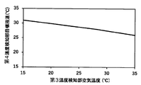
また、図14に示すように、目標温度演算部203Bでは、第3温度検知部7の検知した容器保持部22近傍の空気温度が高いほど、第4温度検知部8の目標温度、すなわち試薬(反応補助液、洗浄液)の温度が低くなるように設定している。
その他の構成・動作は前述した実施例1の自動分析装置と略同じ構成・動作であり、詳細は省略する。
本発明の実施例3の自動分析装置においても、前述した実施例1の自動分析装置とほぼ同様な効果が得られる。
また、容器保持部22の周囲の空気温度、試薬容器9,10内の試薬の温度のうち少なくともいずれか一方の温度を検知する第3温度検知部7を更に備え、液温調整部1B,制御部201Bは、第3温度検知部7で検知される第3温度に基づいて試薬容器9,10へ供給される試薬の温度調整を実行することにより、試薬容器9,10を経て検出容器15に供給される試薬の温度を調整することができ、実施例2に比べて更に分析精度を向上させることができる。
更に、液温調整部1B,制御部201Bは、試薬容器9,10へ供給される試薬の温度を検知する第4温度検知部8を更に備え、液温調整部1B,制御部201Bは、第3温度に基づいて第4温度検知部8で検知される第4温度の目標値を求め、第4温度と目標値との差分に基づいて温度調整を実行する、特に液温調整部1B,制御部201Bは、第3温度が高いほど第4温度が低く、第3温度が低いほど第4温度が高くなるように温度調整を実行することで、更に高い精度で試薬容器9,10を経て検出容器15に供給される試薬の温度を調整することができる。
なお、以上の説明では、第1温度検知部4は処理部3近傍の空気温度を検知することとしたが、替わりに、若しくは加えて反応容器11内の試薬の温度を検知することができる。また、第3温度検知部7は容器保持部22の近傍の空気温度を検知する場合について説明したが、替わりに、若しくは加えて試薬容器9および/又は試薬容器10内の液温を検知することができる。
<実施例4>
本発明の実施例4の自動分析装置について図15乃至図17を用いて説明する。図15は本実施例4における自動分析装置のうち、処理部および液温調整部の拡大図である。図16は本実施例4における自動分析装置の液温調整部の制御方法を示すブロック図である。図17は本実施例4における自動分析装置の第1温度検知部の空気温度および発熱量変化量の推定値と、第2温度検知部の目標液温の関係の一例を示す図である。
本発明の実施例4の自動分析装置について図15乃至図17を用いて説明する。図15は本実施例4における自動分析装置のうち、処理部および液温調整部の拡大図である。図16は本実施例4における自動分析装置の液温調整部の制御方法を示すブロック図である。図17は本実施例4における自動分析装置の第1温度検知部の空気温度および発熱量変化量の推定値と、第2温度検知部の目標液温の関係の一例を示す図である。
図15に示すように、本実施例では、搬送機構51に設けられたモータやソレノイドの検知部70,71、撹拌部13を回転駆動させるモータ14の検知部72を設けてモータ等に流れる電流を検知する。検知部70,71,72では、電圧あるいは電流と電圧の両方を検知しても良い。
また、図15および図16に示すように、制御部201Cには、第2センサ入力処理部209C、発熱量推定部210Cおよび発熱量変化量演算部211Cを設ける。
その上で、図16に示すように、本実施例の制御部201Cでは、検知部70,71,72で検知されたモータ等の電流に基づいて、発熱量推定部210Cにおいて発熱量を推定し、発熱量変化量演算部211Cにおいて発熱量の変化量を演算する。
次に、目標温度演算部203Cにおいて、第1温度検知部4で検知した処理部3近傍の空気温度と、発熱量変化量演算部211Cで求められた発熱量の変化量に基づいて、第2温度検知部5での目標温度205Cを演算する。
ペルチェ素子制御部204Cは、第2温度検知部5での目標温度205Cと第2温度検知部5で実際に検知した温度に基づいて、第1ペルチェ素子2に出力される電流のデューティを制御する。
図17に、発熱量変化量演算部211Cで求められた発熱量の変化量をパラメータとした、第1温度検知部4の検知した温度と第2温度検知部5の目標液温との関係の一例を示す。
図17に示すように、第1温度検知部4の検知した処理部3近傍の空気温度が高いほど、第2温度検知部5の目標温度、すなわち試薬(置換液)の温度が低くなるように設定するとともに、発熱量の増加量が大きいほど第2温度検知部5の目標液温を低く設定し、発熱量の減少量が大きいほど第2温度検知部5の目標液温を高く設定するようにしている。
その他の構成・動作は前述した実施例1の自動分析装置と略同じ構成・動作であり、詳細は省略する。
本発明の実施例4の自動分析装置においても、前述した実施例1の自動分析装置とほぼ同様な効果が得られる。
また、自動分析装置100内に存在する発熱体の発熱量を推定する推定部を更に備え、液温調整部1,制御部201Cは、第1温度に加えて推定部で推定された発熱量の変化量に基づいて第2温度検知部5で検知される第2温度の目標値を求め、第2温度と目標値との差分に基づいて温度調整を実行する、特に液温調整部1,制御部201Cは、発熱量の増加量が多いほど第2温度が低く、発熱量の増加量が少ないほど第2温度が高くなるように温度調整を実行することにより、発熱量の変動に対応して第1ペルチェ素子2の冷却能力が調整されるので、磁気分離部12や撹拌部13における試薬の温度を更に高精度で一定の温度範囲に保つことができる。従って、更に適切な条件で検体と試薬の反応を行うことができ、検出器16における分析精度を更に向上させることが可能である。
なお、本実施例のような発熱量の推定は、実施例2の液温調整部1Aや実施例3の液温調整部1Bで実施することができる。
また、第1温度に加えて推定部で推定された発熱量の変化量に基づいて第2温度検知部5で検知される第2温度の目標値を求め、第2温度と目標値との差分に基づいて温度調整を実行する場合に限られず、液温調整部1,制御部201Cは、実施例3で説明した第3温度に加えて、推定部で推定された発熱量の変化量に基づいて実施例3で説明した第4温度の目標値を求め、第4温度と目標値との差分に基づいて温度調整を実行、特に発熱量の増加量が多いほど第4温度が低く、発熱量の増加量が少ないほど第4温度が高くなるように温度調整を実行することができる。
これによって、試薬容器9,10を経て検出容器15に供給される試薬の温度を更に高精度に調整することができ、検出器16における分析精度を更に向上させることができる。
<その他>
なお、本発明は、上記の実施例に限定されるものではなく、様々な変形例が含まれる。上記の実施例は本発明を分かりやすく説明するために詳細に説明したものであり、必ずしも説明した全ての構成を備えるものに限定されるものではない。
なお、本発明は、上記の実施例に限定されるものではなく、様々な変形例が含まれる。上記の実施例は本発明を分かりやすく説明するために詳細に説明したものであり、必ずしも説明した全ての構成を備えるものに限定されるものではない。
また、ある実施例の構成の一部を他の実施例の構成に置き換えることも可能であり、また、ある実施例の構成に他の実施例の構成を加えることも可能である。また、各実施例の構成の一部について、他の構成の追加・削除・置換をすることも可能である。
1,1A,1B…液温調整部(液温調整装置)
2…第1ペルチェ素子
3…処理部
4…第1温度検知部
5…第2温度検知部
6…第2ペルチェ素子
7…第3温度検知部
8…第4温度検知部
9,10…試薬容器
11…反応容器
12…磁気分離部
13…撹拌部
14…モータ(発熱体)
15…検出容器
16…検出器
21…吸引ノズル
22…容器保持部
26,27,28,29…シリンジポンプ(供給機器)
30,31,32…試薬貯蔵部(供給機器)
34,35,36,37,38,39,40,41…電磁弁(供給機器)
42…廃液容器
43…チューブ
51…搬送機構(発熱体)
52…吸引ノズル(供給機器)
53…吐出ノズル(供給機器)
60…反応テーブル
70,71,72…検知部
100…自動分析装置
101,101A,101B…金属ブロック
102…断熱材
103…熱拡散板
104,105,106…サーマルインタフェース(グリース)
107…フィンベース
108…フィン
109…ファン
110,111,112…螺旋パイプ
113,114,115,116,117,118…コネクタ
201,201A,201B,201C…制御部(液温調整装置)
202,202A,202B…センサ入力処理部
203,203A,203B,203C…目標温度演算部
204,204A,204C……ペルチェ素子制御部
204B…第1ペルチェ素子制御部
205,205B,205C,207B…目標温度
206B…第2ペルチェ素子制御部
209C…第2センサ入力処理部(推定部)
210C…発熱量推定部(推定部)
211C…発熱量変化量演算部(推定部)
301…ラック
302…検体容器
303…検体分注ノズル
306…反応容器搬送機構
307…検体分注チップ・反応容器保持部材
311…試薬ディスク
314…試薬分注ノズル
317…ラック搬送ライン
319…制御装置
Claims (12)
- 検体と試薬を反応させ、この反応させた反応液を測定する自動分析装置であって、
前記検体の分析前の処理を行う処理部と、
前記処理部に設置された反応容器へ前記試薬を供給される供給機器と、
前記供給機器によって反応容器に供給される前記試薬の温度を調整する液温調整装置と、
前記処理部内の空気の温度、前記反応容器に供給された前記試薬の温度のうち少なくともいずれか一方の温度を検知する第1温度検知部と、を備え、
前記液温調整装置は、前記第1温度検知部で検知される第1温度に基づいて前記試薬の温度調整を実行する
ことを特徴とする自動分析装置。 - 請求項1に記載の自動分析装置において、
前記液温調整装置内に配置され、前記処理部へ供給される前記試薬の温度を検知する第2温度検知部を更に備え、
前記液温調整装置は、前記第1温度に基づいて前記第2温度検知部で検知される第2温度の目標値を求め、前記第2温度と前記目標値との差分に基づいて温度調整を実行する
ことを特徴とする自動分析装置。 - 請求項2に記載の自動分析装置において、
前記液温調整装置は、前記第1温度が高いほど前記第2温度が低く、前記第1温度が低いほど前記第2温度が高くなるように温度調整を実行する
ことを特徴とする自動分析装置。 - 請求項1に記載の自動分析装置において、
前記検体の分析を行う検出容器に供給される試薬を一時的に保持する試薬容器と、
前記反応容器および前記試薬容器を保持する容器保持部と、を更に備え、
前記液温調整装置は、前記試薬容器へ供給される試薬の温度についても第1温度に基づいて調整する
ことを特徴とする自動分析装置。 - 請求項4に記載の自動分析装置において、
前記容器保持部の周囲の空気温度、前記試薬容器内の試薬の温度のうち少なくともいずれか一方の温度を検知する第3温度検知部を更に備え、
前記液温調整装置は、前記第3温度検知部で検知される第3温度に基づいて前記試薬容器へ供給される試薬の温度調整を実行する
ことを特徴とする自動分析装置。 - 請求項5に記載の自動分析装置において、
前記液温調整装置は、前記試薬容器へ供給される試薬の温度を検知する第4温度検知部を更に備え、
前記液温調整装置は、前記第3温度に基づいて前記第4温度検知部で検知される第4温度の目標値を求め、前記第4温度と前記目標値との差分に基づいて温度調整を実行する
ことを特徴とする自動分析装置。 - 請求項6に記載の自動分析装置において、
前記液温調整装置は、前記第3温度が高いほど前記第4温度が低く、記第3温度が低いほど前記第4温度が高くなるように温度調整を実行する
ことを特徴とする自動分析装置。 - 請求項2に記載の自動分析装置において、
前記自動分析装置内に存在する発熱体の発熱量を推定する推定部を更に備え、
前記液温調整装置は、前記第1温度に加えて前記推定部で推定された前記発熱量の変化量に基づいて前記第2温度の目標値を求め、前記第2温度と前記目標値との差分に基づいて温度調整を実行する
ことを特徴とする自動分析装置。 - 請求項8に記載の自動分析装置において、
前記液温調整装置は、前記発熱量の増加量が多いほど前記第2温度が低く、前記発熱量の増加量が少ないほど前記第2温度が高くなるように温度調整を実行する
ことを特徴とする自動分析装置。 - 請求項6に記載の自動分析装置において、
前記自動分析装置内に存在する発熱体の発熱量を推定する推定部を更に備え、
前記液温調整装置は、前記第3温度に加えて前記推定部で推定された前記発熱量の変化量に基づいて前記第4温度の目標値を求め、前記第4温度と前記目標値との差分に基づいて温度調整を実行する
ことを特徴とする自動分析装置。 - 請求項10に記載の自動分析装置において、
前記液温調整装置は、前記発熱量の増加量が多いほど前記第4温度が低く、前記発熱量の増加量が少ないほど前記第4温度が高くなるように温度調整を実行する
ことを特徴とする自動分析装置。 - 請求項1に記載の自動分析装置において、
前記処理部は、前記反応液に対して処理を行う部分である
ことを特徴とする自動分析装置。
Priority Applications (3)
| Application Number | Priority Date | Filing Date | Title |
|---|---|---|---|
| US17/285,972 US11953508B2 (en) | 2018-12-27 | 2019-10-09 | Automatic analysis device |
| EP19905745.6A EP3904888A4 (en) | 2018-12-27 | 2019-10-09 | AUTOMATED ANALYZER |
| CN201980068157.9A CN112912734A (zh) | 2018-12-27 | 2019-10-09 | 自动分析装置 |
Applications Claiming Priority (2)
| Application Number | Priority Date | Filing Date | Title |
|---|---|---|---|
| JP2018-246148 | 2018-12-27 | ||
| JP2018246148A JP7157658B2 (ja) | 2018-12-27 | 2018-12-27 | 自動分析装置 |
Publications (1)
| Publication Number | Publication Date |
|---|---|
| WO2020137081A1 true WO2020137081A1 (ja) | 2020-07-02 |
Family
ID=71126263
Family Applications (1)
| Application Number | Title | Priority Date | Filing Date |
|---|---|---|---|
| PCT/JP2019/039745 WO2020137081A1 (ja) | 2018-12-27 | 2019-10-09 | 自動分析装置 |
Country Status (5)
| Country | Link |
|---|---|
| US (1) | US11953508B2 (ja) |
| EP (1) | EP3904888A4 (ja) |
| JP (1) | JP7157658B2 (ja) |
| CN (1) | CN112912734A (ja) |
| WO (1) | WO2020137081A1 (ja) |
Cited By (1)
| Publication number | Priority date | Publication date | Assignee | Title |
|---|---|---|---|---|
| WO2024042808A1 (ja) * | 2022-08-23 | 2024-02-29 | 株式会社日立ハイテク | 自動分析装置 |
Families Citing this family (3)
| Publication number | Priority date | Publication date | Assignee | Title |
|---|---|---|---|---|
| WO2023053691A1 (ja) * | 2021-09-30 | 2023-04-06 | 株式会社日立ハイテク | 自動分析装置 |
| JPWO2023127878A1 (ja) * | 2021-12-28 | 2023-07-06 | ||
| US12050232B2 (en) * | 2021-12-31 | 2024-07-30 | Instrumentation Laboratory Company | Systems and methods for probe tip heating |
Citations (6)
| Publication number | Priority date | Publication date | Assignee | Title |
|---|---|---|---|---|
| JP2004037161A (ja) * | 2002-07-01 | 2004-02-05 | Sysmex Corp | 試料分析装置 |
| US20070104614A1 (en) * | 2005-11-10 | 2007-05-10 | Shenzhen Mindray Bio-Medical Electronics Co., Ltd. | Automatic chemistry analyzer and analyzing method |
| JP2010066108A (ja) * | 2008-09-10 | 2010-03-25 | Olympus Corp | 自動分析装置および自動分析装置の駆動制御方法 |
| JP2012159392A (ja) * | 2011-01-31 | 2012-08-23 | Sysmex Corp | 分析装置及び分析方法 |
| JP2013246090A (ja) | 2012-05-28 | 2013-12-09 | Hitachi High-Technologies Corp | 自動分析装置及び前処理装置 |
| WO2018047545A1 (ja) * | 2016-09-08 | 2018-03-15 | 株式会社 日立ハイテクノロジーズ | 自動分析装置 |
Family Cites Families (16)
| Publication number | Priority date | Publication date | Assignee | Title |
|---|---|---|---|---|
| JPS63205567A (ja) | 1987-02-20 | 1988-08-25 | Nittec Co Ltd | 試薬用ピペツト装置 |
| US6558626B1 (en) * | 2000-10-17 | 2003-05-06 | Nomadics, Inc. | Vapor sensing instrument for ultra trace chemical detection |
| US7691334B2 (en) * | 2005-09-20 | 2010-04-06 | Yamaha Corporation | Temperature control apparatus for microchemical chip |
| JP5205802B2 (ja) * | 2007-05-11 | 2013-06-05 | ソニー株式会社 | リアルタイムpcr装置 |
| JP5393608B2 (ja) * | 2010-07-20 | 2014-01-22 | 株式会社日立ハイテクノロジーズ | 自動分析装置 |
| CN102537978A (zh) * | 2010-12-16 | 2012-07-04 | 株式会社久保田 | 污泥燃烧控制方法以及污泥燃烧设备 |
| CN102623725A (zh) * | 2011-01-30 | 2012-08-01 | 扬光绿能股份有限公司 | 燃料电池系统及其控制方法 |
| JP2013088164A (ja) * | 2011-10-14 | 2013-05-13 | Hitachi High-Technologies Corp | 自動分析装置 |
| JP5882177B2 (ja) * | 2012-10-19 | 2016-03-09 | 株式会社日立製作所 | 生体物質回収方法及び生体物質回収装置 |
| EP3527991B1 (en) * | 2012-12-26 | 2020-04-22 | Hitachi High-Technologies Corporation | Automatic analyzer |
| US20160018426A1 (en) * | 2014-07-21 | 2016-01-21 | Sakae Co., Ltd. | Automatic analysis device |
| JP6546374B2 (ja) * | 2014-07-21 | 2019-07-17 | 株式会社サカエ | 自動分析装置 |
| JP6718679B2 (ja) * | 2015-12-28 | 2020-07-08 | マクセルホールディングス株式会社 | 温風乾燥機 |
| CN108181210A (zh) * | 2016-12-08 | 2018-06-19 | 深圳市帝迈生物技术有限公司 | 一种血液细胞分析仪及其反应池温度控制装置 |
| US11300488B2 (en) | 2017-02-07 | 2022-04-12 | Hitachi High-Tech Corporation | Automatic analysis device |
| JP6753522B2 (ja) * | 2017-04-26 | 2020-09-09 | 株式会社島津製作所 | 送液装置及び流体クロマトグラフ |
-
2018
- 2018-12-27 JP JP2018246148A patent/JP7157658B2/ja active Active
-
2019
- 2019-10-09 US US17/285,972 patent/US11953508B2/en active Active
- 2019-10-09 WO PCT/JP2019/039745 patent/WO2020137081A1/ja unknown
- 2019-10-09 EP EP19905745.6A patent/EP3904888A4/en active Pending
- 2019-10-09 CN CN201980068157.9A patent/CN112912734A/zh active Pending
Patent Citations (6)
| Publication number | Priority date | Publication date | Assignee | Title |
|---|---|---|---|---|
| JP2004037161A (ja) * | 2002-07-01 | 2004-02-05 | Sysmex Corp | 試料分析装置 |
| US20070104614A1 (en) * | 2005-11-10 | 2007-05-10 | Shenzhen Mindray Bio-Medical Electronics Co., Ltd. | Automatic chemistry analyzer and analyzing method |
| JP2010066108A (ja) * | 2008-09-10 | 2010-03-25 | Olympus Corp | 自動分析装置および自動分析装置の駆動制御方法 |
| JP2012159392A (ja) * | 2011-01-31 | 2012-08-23 | Sysmex Corp | 分析装置及び分析方法 |
| JP2013246090A (ja) | 2012-05-28 | 2013-12-09 | Hitachi High-Technologies Corp | 自動分析装置及び前処理装置 |
| WO2018047545A1 (ja) * | 2016-09-08 | 2018-03-15 | 株式会社 日立ハイテクノロジーズ | 自動分析装置 |
Non-Patent Citations (1)
| Title |
|---|
| See also references of EP3904888A4 |
Cited By (1)
| Publication number | Priority date | Publication date | Assignee | Title |
|---|---|---|---|---|
| WO2024042808A1 (ja) * | 2022-08-23 | 2024-02-29 | 株式会社日立ハイテク | 自動分析装置 |
Also Published As
| Publication number | Publication date |
|---|---|
| JP7157658B2 (ja) | 2022-10-20 |
| JP2020106424A (ja) | 2020-07-09 |
| CN112912734A (zh) | 2021-06-04 |
| US11953508B2 (en) | 2024-04-09 |
| US20210382078A1 (en) | 2021-12-09 |
| EP3904888A4 (en) | 2022-09-28 |
| EP3904888A1 (en) | 2021-11-03 |
Similar Documents
| Publication | Publication Date | Title |
|---|---|---|
| WO2020137081A1 (ja) | 自動分析装置 | |
| CN113711052B (zh) | 自动分析装置 | |
| JP6549329B2 (ja) | 自動分析装置 | |
| JP4331407B2 (ja) | サンプルの自動分析のための構造および方法 | |
| US11498076B2 (en) | Methods and apparatus for rapid heating of biological specimens | |
| JP7028744B2 (ja) | 自動分析装置 | |
| JP5921336B2 (ja) | 自動分析装置及び前処理装置 | |
| EP2856039B1 (en) | Method and system providing a temperature- controlled process liquid | |
| JP6126387B2 (ja) | 二重管構造試料吸引ノズルを備えた電解質分析装置 | |
| JP7212632B2 (ja) | 温調システム | |
| JP2009276214A (ja) | 免疫分析装置 | |
| WO2024042808A1 (ja) | 自動分析装置 | |
| WO2018230217A1 (ja) | 自動分析装置 | |
| JP2009264908A (ja) | 自動分析装置 | |
| JP2023526983A (ja) | 生体サンプルを処理する装置及び方法 |
Legal Events
| Date | Code | Title | Description |
|---|---|---|---|
| 121 | Ep: the epo has been informed by wipo that ep was designated in this application |
Ref document number: 19905745 Country of ref document: EP Kind code of ref document: A1 |
|
| NENP | Non-entry into the national phase |
Ref country code: DE |
|
| ENP | Entry into the national phase |
Ref document number: 2019905745 Country of ref document: EP Effective date: 20210727 |