WO2020129511A1 - ベルト式無段変速機 - Google Patents
ベルト式無段変速機 Download PDFInfo
- Publication number
- WO2020129511A1 WO2020129511A1 PCT/JP2019/045072 JP2019045072W WO2020129511A1 WO 2020129511 A1 WO2020129511 A1 WO 2020129511A1 JP 2019045072 W JP2019045072 W JP 2019045072W WO 2020129511 A1 WO2020129511 A1 WO 2020129511A1
- Authority
- WO
- WIPO (PCT)
- Prior art keywords
- pressure
- target
- ratio
- primary
- continuously variable
- Prior art date
- Legal status (The legal status is an assumption and is not a legal conclusion. Google has not performed a legal analysis and makes no representation as to the accuracy of the status listed.)
- Ceased
Links
Images



Classifications
-
- F—MECHANICAL ENGINEERING; LIGHTING; HEATING; WEAPONS; BLASTING
- F16—ENGINEERING ELEMENTS AND UNITS; GENERAL MEASURES FOR PRODUCING AND MAINTAINING EFFECTIVE FUNCTIONING OF MACHINES OR INSTALLATIONS; THERMAL INSULATION IN GENERAL
- F16H—GEARING
- F16H59/00—Control inputs to control units of change-speed- or reversing-gearings for conveying rotary motion
- F16H59/68—Inputs being a function of gearing status
- F16H59/70—Inputs being a function of gearing status dependent on the ratio established
-
- F—MECHANICAL ENGINEERING; LIGHTING; HEATING; WEAPONS; BLASTING
- F16—ENGINEERING ELEMENTS AND UNITS; GENERAL MEASURES FOR PRODUCING AND MAINTAINING EFFECTIVE FUNCTIONING OF MACHINES OR INSTALLATIONS; THERMAL INSULATION IN GENERAL
- F16H—GEARING
- F16H61/00—Control functions within control units of change-speed- or reversing-gearings for conveying rotary motion ; Control of exclusively fluid gearing, friction gearing, gearings with endless flexible members or other particular types of gearing
- F16H61/02—Control functions within control units of change-speed- or reversing-gearings for conveying rotary motion ; Control of exclusively fluid gearing, friction gearing, gearings with endless flexible members or other particular types of gearing characterised by the signals used
-
- F—MECHANICAL ENGINEERING; LIGHTING; HEATING; WEAPONS; BLASTING
- F16—ENGINEERING ELEMENTS AND UNITS; GENERAL MEASURES FOR PRODUCING AND MAINTAINING EFFECTIVE FUNCTIONING OF MACHINES OR INSTALLATIONS; THERMAL INSULATION IN GENERAL
- F16H—GEARING
- F16H61/00—Control functions within control units of change-speed- or reversing-gearings for conveying rotary motion ; Control of exclusively fluid gearing, friction gearing, gearings with endless flexible members or other particular types of gearing
- F16H61/66—Control functions within control units of change-speed- or reversing-gearings for conveying rotary motion ; Control of exclusively fluid gearing, friction gearing, gearings with endless flexible members or other particular types of gearing specially adapted for continuously variable gearings
- F16H61/662—Control functions within control units of change-speed- or reversing-gearings for conveying rotary motion ; Control of exclusively fluid gearing, friction gearing, gearings with endless flexible members or other particular types of gearing specially adapted for continuously variable gearings with endless flexible members
Definitions
- the present invention relates to a belt type continuously variable transmission that controls the hydraulic pressure of a secondary pulley by feedback control.
- Patent Document 1 in a hydraulic control device for a belt type continuously variable transmission for a vehicle, a target secondary pressure is calculated based on an input torque and a target gear ratio, and a secondary pressure control actuator is generated so that the target secondary pressure is generated. By driving, the occurrence of belt slip is avoided.
- the present invention has been made in view of the above problems, and an object of the present invention is to provide a control device for a belt-type continuously variable transmission that can ensure the stability of gear change control.
- a belt type continuously variable transmission equipped with Based on the input torque to the belt type continuously variable transmission, the target secondary pressure of the secondary pulley is calculated, feedback control by integral control is performed based on the deviation between the target secondary pressure and the actual secondary pressure, Based on the balance thrust ratio map, calculate the balance thrust ratio, which is the ratio of the primary pressure and the secondary pressure for balancing the gear ratio to a constant value, Compute a secondary pressure compensation value based on the deviation between the target secondary pressure and the actual secondary pressure,
- the target gear ratio is calculated based on the running state, and the differential thrust command value of the primary pulley is calculated based on the deviation between the actual gear ratio and the target gear ratio, A value obtained by multiplying the target secondary pressure by the balance thrust ratio, a secondary compensating hydraulic pressure obtained by multiply
- the stability of the shift control can be secured.
- FIG. 1 is a system diagram of a vehicle including a belt type continuously variable transmission according to a first embodiment.
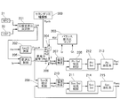
- FIG. 3 is a control block diagram showing a shift control process in the transmission controller of the first embodiment.
- 3 is a balance thrust ratio map used for shift control of the belt type continuously variable transmission according to the first embodiment.
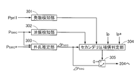
- 3 is a control block diagram illustrating a configuration of a secondary pressure compensating unit according to the first embodiment.
- FIG. 6 is a flowchart showing a secondary pressure compensation process of the first embodiment.
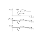
- 5 is a time chart showing the relationship between the deviation and the disturbance in the first embodiment.
- the primary pulley 3 has a fixed sheave 3a formed integrally with the transmission input shaft 2 and a movable sheave 3b movable on the transmission input shaft 2.
- the movable sheave 3b is provided with a primary pressure chamber 3b1, and the hydraulic pressure supplied to the primary pressure chamber 3b1 generates a pressing force between the fixed sheave 3a and the movable sheave 3b to hold the belt 4.
- the secondary pulley 5 has a fixed sheave 5a formed integrally with the transmission output shaft 6 and a movable sheave 5b movable on the transmission output shaft 6.
- the movable sheave 5b is provided with a secondary pressure chamber 5b1, and the hydraulic pressure supplied to the secondary pressure chamber 5b1 generates a pressing force between the fixed sheave 5a and the movable sheave 5b to clamp the belt 4.
- the engine controller 10 controls the engine speed and the engine torque TENG (hereinafter also referred to as the input torque Tin) by controlling the operating state of the engine 1 (fuel injection amount, ignition timing, etc.). Further, in the engine controller 10, a required torque calculation unit that calculates the required torque TD of the driver based on the accelerator opening signal APO detected by the accelerator opening sensor 21 and the vehicle speed signal VSP detected by the vehicle speed sensor 22. It has an engine torque calculator 10b for calculating an input torque Tin transmitted to the transmission input shaft 2.
- TENG engine torque TENG
- the control valve unit 30 uses an oil pump 9 driven by a chain on the transmission input shaft 2 as a hydraulic pressure source, and regulates each hydraulic pressure based on a control signal transmitted from the transmission controller 20. Then, the primary pressure and the secondary pressure are supplied to the primary pressure chamber 3b1 and the secondary pressure chamber 5b1, respectively, and shift control is executed.
- the control valve unit 30 includes a primary pressure sensor 31 that detects a primary pressure (hydraulic pressure supplied to the primary pressure chamber 3b1), a secondary pressure sensor 32 that detects a secondary pressure (hydraulic pressure supplied to the secondary pressure chamber 5b1), Have. Further, the primary pulley 3 has a primary rotation speed sensor 23 that detects the rotation speed of the primary pulley 3. The secondary pulley 5 has a secondary rotation speed sensor 24 that detects the rotation speed of the secondary pulley 5. The value detected by each sensor is output to the transmission controller 20.
- the target secondary pressure Psec* is multiplied by the balance thrust ratio Kbl to calculate the balance thrust equivalent hydraulic pressure Pbl. That is, the pulley thrust is obtained by multiplying the secondary pressure Psec and the primary pressure Ppri by the specifications of the belt type continuously variable transmission CVT such as the pulley pressure receiving area. Since these parameters are fixed values and the control target is hydraulic pressure, in the first embodiment, calculation is performed based on hydraulic pressure instead of thrust. Further, the secondary pressure compensation value Pprih calculated by the secondary pressure compensating unit 300 described later is multiplied by the balance thrust ratio Kbl to calculate the secondary compensation hydraulic pressure Pb2. Then, the balance thrust equivalent hydraulic pressure Pb1 and the secondary compensation hydraulic pressure Pb2 are added.
- the gear ratio control unit 205 calculates the feedback hydraulic pressure based on the deviation between the target gear ratio Ip* and the actual gear ratio Ip. For example, the hydraulic pressure (hereinafter referred to as feedback pressure Pfb) that is added to or subtracted from the current primary pressure Ppri by PI control or PID control is output.
- the primary pressure calculation unit 206 adds the balance thrust equivalent hydraulic pressure Pbl, the secondary compensation hydraulic pressure Pb2, and the feedback pressure Pfb to calculate the primary pressure command value Ppri1.
- the primary-side current conversion unit 207 converts the primary pressure command value Ppri1 into a primary solenoid current command value.
- the primary solenoid current control unit 208 performs servo control so that the primary solenoid current becomes the primary solenoid current command value.
- the secondary pressure integration control unit 209 calculates the secondary pressure command value Psec1 by integral control based on the deviation ⁇ Psec between the target secondary pressure Psec* and the current actual secondary pressure Psec.
- the secondary-side current conversion unit 210 converts the secondary pressure command value Psec1 into a secondary solenoid current command value.
- the secondary solenoid current control unit 211 performs servo control so that the secondary solenoid current becomes the secondary solenoid current command value.
- the primary solenoid 212 energizes a solenoid valve that regulates the primary pressure Ppri.
- the current sensor provided in the primary solenoid 212 outputs a current value to the primary solenoid current control unit 208.
- the primary pressure system 213 outputs the primary pressure Ppri regulated by the primary solenoid 212.
- the primary pressure Ppri is detected by the primary pressure sensor 31.
- the secondary solenoid 214 energizes a solenoid valve that regulates the secondary pressure Psec.
- the current sensor provided in the secondary solenoid 214 outputs a current value to the secondary solenoid current control unit 211.
- the secondary pressure system 215 outputs the secondary pressure Psec regulated by the secondary solenoid 214.
- the secondary pressure Psec is detected by the secondary pressure sensor 32.
- the secondary pressure compensator 300 calculates the secondary compensating oil pressure Pb2 based on the deviation between the target secondary pressure Psec* and the current actual secondary pressure Psec, and outputs Pb2 as the secondary compensating oil pressure when a predetermined condition is satisfied. However, when the predetermined condition is not satisfied, the output of the secondary compensation hydraulic pressure Pb2 is prohibited, and 0 is output instead.
- the amplitude of the vibration component is calculated, and when the state in which the amplitude of the hydraulic signal is equal to or larger than the predetermined amplitude continues for the predetermined time or longer, it is determined that the oil vibration is occurring. On the other hand, if it is determined that the oil vibration is occurring and the amplitude is less than the predetermined amplitude for a predetermined time or more, it is determined that the oil vibration is not occurring.
- the disturbance estimation unit 303 regards the deviation ⁇ Psec between the target secondary pressure Psec* and the current actual secondary pressure Psec as the disturbance, and calculates ⁇ Psec as the secondary pressure compensation value Pprih.
- FIG. 6 is a time chart showing the relationship between the deviation ⁇ Psec and the disturbance according to the first embodiment. For example, when the driver greatly depresses the accelerator pedal to perform the kickdown shift, the input torque Tin increases and the target gear ratio Ip* is also changed to the low side. When the target secondary pressure Psec* rises at a stroke due to these changes, the actual secondary pressure Psec also rises so as to follow it.
- the deviation ⁇ Psec is regarded as a disturbance, and the disturbance is compensated for on the primary pulley side, thereby ensuring the stability of the shift control without burdening the control on the secondary pulley side. .. Specifically, the deviation ⁇ Psec is calculated as the secondary pressure compensation value Pprih. Then, the secondary pressure compensation value Pprih is multiplied by the balance thrust ratio Kb1 to calculate the secondary compensation hydraulic pressure Pb2. Next, when calculating the primary pressure command value Ppri1, the secondary compensating hydraulic pressure Pb2 is added to the balance thrust equivalent hydraulic pressure Pb1 and the feedback pressure Pfb.
- the disturbance generated on the secondary pulley side is responded to in advance of the change in the gear ratio on the primary pulley side, so that the shift control can be stabilized.
- the gear ratio changes, and the primary pressure command value Ppri1 changes accordingly.
- FIG. 5 is a flowchart showing the secondary pressure compensation process of the first embodiment.
- the secondary pressure compensation value Pprih is calculated based on the secondary pressure deviation ⁇ Psec.
- the gear ratio deviation is calculated.
- the gear ratio deviation is a value obtained by subtracting the actual gear ratio Ip from the target gear ratio Ip*. If the gear ratio deviation is positive, it means that the gear needs to be shifted to the lower side, and if the gear ratio deviation is negative, it means that the gear needs to be shifted to the higher side.
- step S3 fail experience information is set from the fail conditions.
- the fail condition means that the divergence detecting unit 301 is detecting divergence or the oil vibration detecting unit 302 is detecting oil vibration (corresponding to the second condition). If you are experiencing either, set the fail experience information.
- step S4 the fail experience information is cleared from the return condition.
- the recovery condition means that neither divergence detection is performed nor oil vibration is detected, or the ignition is turned off.
- step S5 it is determined whether or not the actual secondary pressure Psec is a region in which an overshoot (also referred to as O/S) with respect to the target secondary pressure Psec* is likely to occur in the shift control (corresponding to the first condition), If it is in the region where overshoot is likely to occur, the process proceeds to step S6, and if not, the process proceeds to step S9 to prohibit addition of the secondary compensation hydraulic pressure Pb2.
- the region where the overshoot is likely to occur is that the actual gear ratio Ip is lower than the predetermined gear ratio, the actual gear ratio Ip is lower than the target gear ratio Ip*, and the input torque Tin is It represents the case where it is larger than a predetermined value. That is, since the change in the actual secondary pressure Psec becomes large, it is a region where the integral component of the feedback control is considered to be accumulated when the actual secondary pressure Psec reaches the target secondary pressure Psec*.
- step S6 it is determined whether or not the secondary compensating hydraulic pressure Pb2 acts in a direction to reduce the deviation calculated in step S2. If it acts in a direction to reduce the deviation, the process proceeds to step S7. Otherwise, the process proceeds to step S9. Then, the secondary compensation oil pressure Pb2 is prohibited from being added. That is, when the gear ratio deviation is positive, addition is permitted only when the secondary compensation hydraulic pressure Pb2 is positive, and when negative, the addition is prohibited. On the other hand, when the gear ratio deviation is negative, the addition is permitted only when the secondary compensation hydraulic pressure Pb2 is negative, and when the secondary compensation hydraulic pressure Pb2 is positive, the addition is prohibited.
- step S7 it is determined whether or not a failure is being experienced.When a failure is being experienced, the secondary compensating hydraulic pressure Pb2 may be added to accelerate the failure on the primary pulley side. Proceed to S9 to prohibit addition of the secondary compensation hydraulic pressure Pb2. On the other hand, if the fail experience information has been cleared, the process proceeds to step S8. In step S8, the secondary compensation hydraulic pressure Pb2 is added when calculating the primary pressure command value Ppri1.
Landscapes
- Engineering & Computer Science (AREA)
- General Engineering & Computer Science (AREA)
- Mechanical Engineering (AREA)
- Control Of Transmission Device (AREA)
Abstract
本発明のベルト式無段変速機では、バランス推力比マップに基づいて、変速比を一定値にバランスさせるためのバランス推力比(Kbl)を演算し、目標セカンダリ圧(Psec*)と実セカンダリ圧(Psec)との偏差に基づいてセカンダリ圧補償値(Pb2)を演算し、走行状態に基づいて目標変速比(Ip*)を演算し、実変速比(Ip)と目標変速比(Ip*)との偏差に基づいてプライマリプーリの差推力指令値を演算し、目標セカンダリ圧(Psec*)にバランス推力比(Kbl)を乗算した値と、セカンダリ圧補償値(Pprih)にバランス推力比(Kbl)を乗算したセカンダリ補償油圧(Pb2)と、差推力指令値であるフィードバック圧(Pfb)とを加算してプライマリプーリ(3)の目標プライマリ圧(Ppri*)を演算し、実プライマリ圧(Psec)が目標プライマリ圧(Psec*)となるように制御する。
Description
本発明は、セカンダリプーリの油圧をフィードバック制御によって制御するベルト式無段変速機に関する。
特許文献1には、車両用のベルト式無段変速機の油圧制御装置において、入力トルクと目標変速比とに基づいて目標セカンダリ圧を演算し、目標セカンダリ圧が発生するようにセカンダリ圧制御アクチュエータを駆動することで、ベルトスリップの発生を回避している。
しかしながら、目標セカンダリ圧を設定し、実セカンダリ圧が目標セカンダリ圧となるようにフィードバック制御をする際、積分制御を用いると、定常偏差を解消する点で効果的であるものの、目標セカンダリ圧が変更される場面では、実セカンダリ圧が目標セカンダリ圧に対してオーバーシュートし、変速制御を安定させることが困難であった。この傾向は、変速制御の応答性を向上するためにフィードバックゲインを大きくするほど顕著となる。ここで、変速制御の安定性を向上するためには、極力フィードバックゲインを抑えることも考えられるが、フィードバックゲインが小さくなると、変速制御の応答性が悪化し、目標変速比と実変速比との偏差が大きくなるという問題がある。また、変速制御中にフィードバックゲインを変更すると、変速制御系の不安定化を招くという問題がある。
本発明は、上記課題に鑑みてなされたもので、変速制御の安定性を確保可能なベルト式無段変速機の制御装置を提供することを目的とする。
本発明のベルト式無段変速機の制御装置では、プライマリプーリと、セカンダリプーリと、両プーリに巻回されたベルトと、前記プライマリプーリ及び前記セカンダリプーリに制御油圧を供給する油圧制御ユニットと、を備えたベルト式無段変速機であって、
前記ベルト式無段変速機への入力トルクに基づいて、前記セカンダリプーリの目標セカンダリ圧を演算し、該目標セカンダリ圧と実セカンダリ圧との偏差に基づいて積分制御によるフィードバック制御を行い、
バランス推力比マップに基づいて、変速比を一定値にバランスさせるためのプライマリ圧とセカンダリ圧との比であるバランス推力比を演算し、
前記目標セカンダリ圧と前記実セカンダリ圧との偏差に基づいてセカンダリ圧補償値を演算し、
走行状態に基づいて目標変速比を演算し、実変速比と前記目標変速比との偏差に基づいて前記プライマリプーリの差推力指令値を演算し、
前記目標セカンダリ圧に前記バランス推力比を乗算した値と、前記セカンダリ圧補償値に前記バランス推力比を乗算したセカンダリ補償油圧と、前記差推力指令値とを加算して前記プライマリプーリの目標プライマリ圧を演算し、実プライマリ圧が前記目標プライマリ圧となるように制御することとした。
前記ベルト式無段変速機への入力トルクに基づいて、前記セカンダリプーリの目標セカンダリ圧を演算し、該目標セカンダリ圧と実セカンダリ圧との偏差に基づいて積分制御によるフィードバック制御を行い、
バランス推力比マップに基づいて、変速比を一定値にバランスさせるためのプライマリ圧とセカンダリ圧との比であるバランス推力比を演算し、
前記目標セカンダリ圧と前記実セカンダリ圧との偏差に基づいてセカンダリ圧補償値を演算し、
走行状態に基づいて目標変速比を演算し、実変速比と前記目標変速比との偏差に基づいて前記プライマリプーリの差推力指令値を演算し、
前記目標セカンダリ圧に前記バランス推力比を乗算した値と、前記セカンダリ圧補償値に前記バランス推力比を乗算したセカンダリ補償油圧と、前記差推力指令値とを加算して前記プライマリプーリの目標プライマリ圧を演算し、実プライマリ圧が前記目標プライマリ圧となるように制御することとした。
よって、セカンダリプーリにおいて生じる目標セカンダリ圧と実セカンダリ圧との偏差を外乱とみなし、プライマリプーリ側で補償することで変速制御の安定性を確保できる。
〔実施形態1〕
図1は実施形態1のベルト式無段変速機を備えた車両のシステム図である。実施形態1の車両は、内燃機関であるエンジン1と、ベルト式無段変速機CVTとを有し、ディファレンシャルギヤ7を介して駆動輪8に駆動力を伝達する。ベルト式無段変速機CVTは、エンジン1のクランク軸と接続された変速機入力軸2と、変速機入力軸2と一体に回転するプライマリプーリ3と、変速機出力軸6と一体に回転するセカンダリプーリ5と、プライマリプーリ3とセカンダリプーリ5との間に巻回され、動力伝達を行うベルト4と、を有する。
図1は実施形態1のベルト式無段変速機を備えた車両のシステム図である。実施形態1の車両は、内燃機関であるエンジン1と、ベルト式無段変速機CVTとを有し、ディファレンシャルギヤ7を介して駆動輪8に駆動力を伝達する。ベルト式無段変速機CVTは、エンジン1のクランク軸と接続された変速機入力軸2と、変速機入力軸2と一体に回転するプライマリプーリ3と、変速機出力軸6と一体に回転するセカンダリプーリ5と、プライマリプーリ3とセカンダリプーリ5との間に巻回され、動力伝達を行うベルト4と、を有する。
プライマリプーリ3には、変速機入力軸2と一体に形成された固定シーブ3aと、変速機入力軸2の軸上を移動可能な可動シーブ3bとを有する。可動シーブ3bには、プライマリ圧室3b1が設けられ、プライマリ圧室3b1に供給される油圧によって固定シーブ3aと可動シーブ3bとの間に押圧力を発生させ、ベルト4を狭持する。同様に、セカンダリプーリ5には、変速機出力軸6と一体に形成された固定シーブ5aと、変速機出力軸6の軸上を移動可能な可動シーブ5bとを有する。可動シーブ5bには、セカンダリ圧室5b1が設けられ、セカンダリ圧室5b1に供給される油圧によって固定シーブ5aと可動シーブ5bとの間に押圧力を発生させ、ベルト4を挟持する。
エンジンコントローラ10は、エンジン1の運転状態(燃料噴射量や点火タイミング等)を制御することでエンジン回転数及びエンジントルクTENG(以下、入力トルクTinとも記載する。)を制御する。また、エンジンコントローラ10内では、アクセル開度センサ21により検出されたアクセル開度信号APO及び車速センサ22により検出された車速信号VSPに基づいて、運転者の要求トルクTDを演算する要求トルク演算部10aと、変速機入力軸2に伝達される入力トルクTinを演算するエンジントルク演算部10bとを有する。
変速機コントローラ20内では、走行状態に応じたプライマリ圧及びセカンダリ圧を算出し、コントロールバルブユニット30に対して制御信号を出力する。変速機コントローラ20内の詳細については後述する。
コントロールバルブユニット30は、変速機入力軸2にチェーン駆動されるオイルポンプ9を油圧源とし、変速機コントローラ20から送信された制御信号に基づいて各油圧を調圧する。そして、プライマリ圧室3b1及びセカンダリ圧室5b1にそれぞれプライマリ圧及びセカンダリ圧を供給し、変速制御を実行する。コントロールバルブユニット30は、プライマリ圧(プライマリ圧室3b1に供給される油圧)を検出するプライマリ圧センサ31と、セカンダリ圧(セカンダリ圧室5b1に供給される油圧)を検出するセカンダリ圧センサ32と、を有する。また、プライマリプーリ3は、プライマリプーリ3の回転数を検出するプライマリ回転数センサ23を有する。セカンダリプーリ5は、セカンダリプーリ5の回転数を検出するセカンダリ回転数センサ24を有する。各センサで検出された値は、変速機コントローラ20に出力される。
図2は実施形態1の変速機コントローラ内における変速制御処理を表す制御ブロック図である。
目標変速比演算部201では、アクセル開度信号APOと車速信号VSPに基づいて目標変速比Ip*を演算する。この目標変速比Ip*は、エンジン1が最適燃費を達成するように予め設定された変速特性に基づいて行われる。
セカンダリ圧演算部202では、入力トルクTinに基づいてセカンダリプーリ5で必要なクランプ力を確保した目標セカンダリ圧Psec*を演算する。
目標変速比演算部201では、アクセル開度信号APOと車速信号VSPに基づいて目標変速比Ip*を演算する。この目標変速比Ip*は、エンジン1が最適燃費を達成するように予め設定された変速特性に基づいて行われる。
セカンダリ圧演算部202では、入力トルクTinに基づいてセカンダリプーリ5で必要なクランプ力を確保した目標セカンダリ圧Psec*を演算する。
バランス推力比演算部203では、プライマリ回転数センサ23により検出されたプライマリ回転数Npriとセカンダリ回転数センサ24により検出されたセカンダリ回転数Nsecとに基づいて演算された変速比Ipと、要求トルクTDに基づいて設定される入力トルクTinの比であるトルク比Qtとに基づいて、予め設定されたバランス推力比マップからバランス推力比Kblを算出する。バランス推力比Kblとは、あるトルク比である変速比を達成してバランスする(その変速比を維持する)際のプライマリ推力とセカンダリ推力との比である。
図3は、実施形態1のベルト式無段変速機の変速制御に使用されるバランス推力比マップである。このバランス推力比マップには、各変速比においてトルク比に対するバランス推力比Kblの特性が設定されている。バランス推力比演算部203は、バランス推力比マップから現在の変速比Ipに対応する特性を選択し、選択された特性においてトルク比Qtに対応するバランス推力比Kblを算出する。
バランス推力演算部204では、目標セカンダリ圧Psec*にバランス推力比Kblを乗算し、バランス推力相当油圧Pblを演算する。すなわち、セカンダリ圧Psecやプライマリ圧Ppriにプーリ受圧面積等のベルト式無段変速機CVTの諸元を乗算することでプーリ推力となる。これら諸元は固定値であり、制御対象は油圧であるため、実施形態1では、推力に代えて油圧に基づいて算出する。また、後述するセカンダリ圧補償部300により演算されたセカンダリ圧補償値Pprihにバランス推力比Kblを乗算し、セカンダリ補償油圧Pb2を演算する。そして、バランス推力相当油圧Pb1とセカンダリ補償油圧Pb2を加算する。
変速比制御部205では、目標変速比Ip*と実変速比Ipとの偏差に基づくフィードバック油圧を演算する。例えば、PI制御やPID制御によって現在のプライマリ圧Ppriに加減算する油圧(以下、フィードバック圧Pfbと記載する。)を出力する。
プライマリ圧演算部206では、バランス推力相当油圧Pblとセカンダリ補償油圧Pb2とフィードバック圧Pfbとを加算し、プライマリ圧指令値Ppri1を演算する。
プライマリ側電流換算部207では、プライマリ圧指令値Ppri1に応じたプライマリソレノイド電流指令値に換算する。
プライマリソレノイド電流制御部208では、プライマリソレノイド電流がプライマリソレノイド電流指令値となるようにサーボ制御を行う。
プライマリ圧演算部206では、バランス推力相当油圧Pblとセカンダリ補償油圧Pb2とフィードバック圧Pfbとを加算し、プライマリ圧指令値Ppri1を演算する。
プライマリ側電流換算部207では、プライマリ圧指令値Ppri1に応じたプライマリソレノイド電流指令値に換算する。
プライマリソレノイド電流制御部208では、プライマリソレノイド電流がプライマリソレノイド電流指令値となるようにサーボ制御を行う。
セカンダリ圧積分制御部209では、目標セカンダリ圧Psec*と現在の実セカンダリ圧Psecとの偏差ΔPsecに基づく積分制御によりセカンダリ圧指令値Psec1を演算する。
セカンダリ側電流換算部210では、セカンダリ圧指令値Psec1に応じたセカンダリソレノイド電流指令値に換算する。
セカンダリソレノイド電流制御部211では、セカンダリソレノイド電流がセカンダリソレノイド電流指令値となるようにサーボ制御を行う。
プライマリソレノイド212では、プライマリ圧Ppriを調圧するソレノイドバルブに通電する。プライマリソレノイド212に設けられた電流センサは、プライマリソレノイド電流制御部208に電流値を出力する。
プライマリ圧系213では、プライマリソレノイド212で調圧されたプライマリ圧Ppriを出力する。プライマリ圧Ppriは、プライマリ圧センサ31により検出される。
セカンダリソレノイド214では、セカンダリ圧Psecを調圧するソレノイドバルブに通電する。セカンダリソレノイド214に設けられた電流センサは、セカンダリソレノイド電流制御部211に電流値を出力する。
セカンダリ圧系215では、セカンダリソレノイド214で調圧されたセカンダリ圧Psecを出力する。セカンダリ圧Psecは、セカンダリ圧センサ32により検出される。
セカンダリ側電流換算部210では、セカンダリ圧指令値Psec1に応じたセカンダリソレノイド電流指令値に換算する。
セカンダリソレノイド電流制御部211では、セカンダリソレノイド電流がセカンダリソレノイド電流指令値となるようにサーボ制御を行う。
プライマリソレノイド212では、プライマリ圧Ppriを調圧するソレノイドバルブに通電する。プライマリソレノイド212に設けられた電流センサは、プライマリソレノイド電流制御部208に電流値を出力する。
プライマリ圧系213では、プライマリソレノイド212で調圧されたプライマリ圧Ppriを出力する。プライマリ圧Ppriは、プライマリ圧センサ31により検出される。
セカンダリソレノイド214では、セカンダリ圧Psecを調圧するソレノイドバルブに通電する。セカンダリソレノイド214に設けられた電流センサは、セカンダリソレノイド電流制御部211に電流値を出力する。
セカンダリ圧系215では、セカンダリソレノイド214で調圧されたセカンダリ圧Psecを出力する。セカンダリ圧Psecは、セカンダリ圧センサ32により検出される。
セカンダリ圧補償部300では、目標セカンダリ圧Psec*と現在の実セカンダリ圧Psecとの偏差に基づいてセカンダリ補償油圧Pb2を演算し、所定の条件が成立している場合はセカンダリ補償油圧としてPb2を出力し、所定の条件が成立していない場合はセカンダリ補償油圧Pb2の出力を禁止し、代わりに0を出力する。
図4は、実施形態1のセカンダリ圧補償部の構成を表す制御ブロック図である。発散検知部301では、最終的な指令信号であるプライマリ圧指令値Ppri1が発散しているか否かを検知する。ここで、指令信号の発散は、周波数が所定値以上で、かつ、振幅が所定値以上の状態が所定時間継続したか否かに基づいて検知する。油振検知部302では、まず、プライマリ圧センサ31もしくはセカンダリ圧センサ32といった油圧センサにより検出された電圧信号を油圧信号に変換し、バンドパスフィルタ処理によってDC成分(制御指令に応じた変動成分)を除去し、振動成分のみを抽出する。そして、振動成分の振幅を算出し、油圧信号の振幅が所定振幅以上の状態が所定時間以上継続した場合には、油振が発生していると判断する。一方、油振が発生していると判断した状態から、振幅が所定振幅未満の状態が所定時間以上継続した場合には、油振が発生していないと判断する。
外乱推定部303では、目標セカンダリ圧Psec*と現在の実セカンダリ圧Psecとの偏差ΔPsecを外乱とみなし、ΔPsecをセカンダリ圧補償値Pprih として演算する。図6は、実施形態1の偏差ΔPsecと外乱との関係を表すタイムチャートである。例えば、運転者がアクセルペダルを大きく踏み込み、キックダウン変速が実施されると、入力トルクTinが増大すると共に、目標変速比Ip*もロー側に大きく変更される。これらの変更に伴って目標セカンダリ圧Psec*が一気に立ち上がると、それに追従するように実セカンダリ圧Psecも上昇する。このとき、実セカンダリ圧Psecの追従遅れによって積分制御によるフィードバック制御系に積分成分が蓄積され、目標セカンダリ圧Psec*に対して実セカンダリ圧Psecがオーバーシュートしやすい。仮に、積分成分の蓄積を回避するためにフィードバックゲインを大きく設定すると、更にオーバーシュートが大きくなり、制御の安定性が低下する。また、フィードバックゲインを小さくすると、追従性が悪化する。
そこで、実施形態1では、偏差ΔPsecを外乱とみなし、この外乱をプライマリプーリ側で補償することで、セカンダリプーリ側での制御に負担を掛けること無く、変速制御の安定性を確保することとした。具体的には、偏差ΔPsecをセカンダリ圧補償値Pprihとして演算する。そして、セカンダリ圧補償値Pprihにバランス推力比Kb1を乗算してセカンダリ補償油圧Pb2を演算する。次に、プライマリ圧指令値Ppri1を演算する際に、バランス推力相当油圧Pb1及びフィードバック圧Pfbにセカンダリ補償油圧Pb2を加算する。これにより、セカンダリプーリ側に生じた外乱をプライマリプーリ側で変速比の変化に先回りして対応するため、変速制御を安定化できる。つまり、偏差ΔPsecによって実セカンダリ圧Psecが変化して変速比が変化し、これに対応するためプライマリ圧指令値Ppri1が変化する、という流れを経ることなく、プライマリ圧指令値Ppri1を演算する際に、バランス推力相当油圧Pb1及びフィードバック圧Pfbにセカンダリ補償油圧Pb2を加算することにより、実セカンダリ圧Psecの変化による変速比の変化に先回りして、変速制御を安定化することができる。
図5は、実施形態1のセカンダリ圧補償処理を表すフローチャートである。
ステップS1では、セカンダリ圧偏差ΔPsecに基づいてセカンダリ圧補償値Pprihを演算する。
ステップS2では、変速比偏差を計算する。変速比偏差とは、目標変速比Ip*から実変速比Ipを減算した値である。変速比偏差が正ならば、よりロー側に変速する必要がある状態を表し、変速比偏差が負ならば、よりハイ側に変速する必要がある状態を表す。
ステップS1では、セカンダリ圧偏差ΔPsecに基づいてセカンダリ圧補償値Pprihを演算する。
ステップS2では、変速比偏差を計算する。変速比偏差とは、目標変速比Ip*から実変速比Ipを減算した値である。変速比偏差が正ならば、よりロー側に変速する必要がある状態を表し、変速比偏差が負ならば、よりハイ側に変速する必要がある状態を表す。
ステップS3では、フェール条件からフェール経験情報をセットする。フェール条件とは、発散検知部301で発散を検知しているか、もしくは油振検知部302で油振を検知していることを表す(第2条件に相当)。いずれか一方を経験しているときは、フェール経験情報をセットする。
ステップS4では、復帰条件からフェール経験情報をクリアする。復帰条件とは、発散検知をしておらず、また、油振検知もしていない、もしくはイグニッションオフを表す。
ステップS5では、変速制御において実セカンダリ圧Psecが目標セカンダリ圧Psec*に対してオーバーシュート(O/Sとも記載する。)が起きそうな領域か否か(第1条件に相当)を判断し、オーバーシュートが起きそうな領域のときはステップS6に進み、それ以外の場合はステップS9に進んでセカンダリ補償油圧Pb2の加算を禁止する。ここで、オーバーシュートが起きそうな領域とは、実変速比Ipが所定変速比よりロー側であり、実変速比Ipが目標変速比Ip*よりもロー側であり、かつ、入力トルクTinが所定値より大きい場合を表す。すなわち、実セカンダリ圧Psecの変化が大きくなるため、実セカンダリ圧Psecが目標セカンダリ圧Psec*に到達する際に、フィードバック制御の積分成分が蓄積されていると考えられる領域である。
ステップS6では、セカンダリ補償油圧Pb2がステップS2で演算した偏差を小さくする方向に作用するか否かを判断し、小さくする方向に作用する場合はステップS7に進み、それ以外の場合はステップS9に進んでセカンダリ補償油圧Pb2の加算を禁止する。すなわち、変速比偏差が正のときは、セカンダリ補償油圧Pb2が正のときのみ加算を許可し、負のときは加算を禁止する。一方、変速比偏差が負のときは、セカンダリ補償油圧Pb2が負のときのみ加算を許可し、正のときは加算を禁止する。
ステップS7では、フェールを経験しているか否かを判断し、フェールを経験しているときは、セカンダリ補償油圧Pb2を加算することでプライマリプーリ側でのフェールが助長されるおそれがあるため、ステップS9に進んでセカンダリ補償油圧Pb2の加算を禁止する。一方、フェール経験情報がクリアされている場合は、ステップS8に進む。
ステップS8では、プライマリ圧指令値Ppri1を演算する際にセカンダリ補償油圧Pb2を加算する。
ステップS8では、プライマリ圧指令値Ppri1を演算する際にセカンダリ補償油圧Pb2を加算する。
以上説明したように、実施形態1では、下記の作用効果が得られる。
(1)プライマリプーリ3と、セカンダリプーリ5と、両プーリに巻回されたベルト4と、前記プライマリプーリ3及び前記セカンダリプーリ5に制御油圧を供給するコントロールバルブユニット30(油圧制御ユニット)と、を備えたベルト式無段変速機CVTであって、
ベルト式無段変速機CVTへの入力トルクTinに基づいて、セカンダリプーリ5の目標セカンダリ圧Psec*を演算し、該目標セカンダリ圧Psec*と実セカンダリ圧Psecとの偏差に基づいて積分制御によるフィードバック制御を行い、
バランス推力比マップに基づいて、変速比を一定値にバランスさせるためのプライマリ圧Ppriとセカンダリ圧Psecとの比であるバランス推力比Kb1を演算し、
目標セカンダリ圧Psec*と実セカンダリ圧Psecとの偏差に基づいてセカンダリ圧補償値Pprihを演算し、
走行状態に基づいて目標変速比Ip*を演算し、実変速比Ipと目標変速比Ip*との偏差に基づいてプライマリプーリ3の差推力指令値を演算し、
前記目標セカンダリ圧に前記バランス推力比Kb1を乗算したバランス推力相当油圧Pb1と、セカンダリ圧補償値Pprihにバランス推力比Kb1を乗算したセカンダリ補償油圧Pb2と、フィードバック圧Pfb(差推力指令値)とを加算してプライマリプーリ3の目標プライマリ圧Ppri*を演算し、実プライマリ圧Ppriが目標プライマリ圧Ppri*となるように制御することとした。
よって、セカンダリプーリ5において生じる目標セカンダリ圧Psec*と実セカンダリ圧Psecとの偏差を外乱とみなし、プライマリプーリ側で補償することで変速制御の安定性を確保できる。
(1)プライマリプーリ3と、セカンダリプーリ5と、両プーリに巻回されたベルト4と、前記プライマリプーリ3及び前記セカンダリプーリ5に制御油圧を供給するコントロールバルブユニット30(油圧制御ユニット)と、を備えたベルト式無段変速機CVTであって、
ベルト式無段変速機CVTへの入力トルクTinに基づいて、セカンダリプーリ5の目標セカンダリ圧Psec*を演算し、該目標セカンダリ圧Psec*と実セカンダリ圧Psecとの偏差に基づいて積分制御によるフィードバック制御を行い、
バランス推力比マップに基づいて、変速比を一定値にバランスさせるためのプライマリ圧Ppriとセカンダリ圧Psecとの比であるバランス推力比Kb1を演算し、
目標セカンダリ圧Psec*と実セカンダリ圧Psecとの偏差に基づいてセカンダリ圧補償値Pprihを演算し、
走行状態に基づいて目標変速比Ip*を演算し、実変速比Ipと目標変速比Ip*との偏差に基づいてプライマリプーリ3の差推力指令値を演算し、
前記目標セカンダリ圧に前記バランス推力比Kb1を乗算したバランス推力相当油圧Pb1と、セカンダリ圧補償値Pprihにバランス推力比Kb1を乗算したセカンダリ補償油圧Pb2と、フィードバック圧Pfb(差推力指令値)とを加算してプライマリプーリ3の目標プライマリ圧Ppri*を演算し、実プライマリ圧Ppriが目標プライマリ圧Ppri*となるように制御することとした。
よって、セカンダリプーリ5において生じる目標セカンダリ圧Psec*と実セカンダリ圧Psecとの偏差を外乱とみなし、プライマリプーリ側で補償することで変速制御の安定性を確保できる。
(2)実変速比Ipが目標変速比Ip*よりロー側のときは、セカンダリ補償油圧Pb2を加算することでハイ側に変速する場合のみセカンダリ補償油圧Pb2を加算し、実変速比Ipが目標変速比Ip*よりハイ側のときは、セカンダリ補償油圧Pb2を加算することでロー側に変速する場合のみセカンダリ補償油圧Pb2を加算することとした。
これにより、セカンダリ補償油圧Pb2を加算することで目標変速比Ip*と実変速比Ipとの偏差が収束する場合のみ、セカンダリ圧補償処理を実施することができ、変速制御の安定性を確保できる。
これにより、セカンダリ補償油圧Pb2を加算することで目標変速比Ip*と実変速比Ipとの偏差が収束する場合のみ、セカンダリ圧補償処理を実施することができ、変速制御の安定性を確保できる。
(3)目標変速比Ip*が所定変速比よりロー側であり、実変速比Ipが目標変速比Ip*よりもロー側であって、かつ、入力トルクTinが所定値以上である第1条件が成立したときにセカンダリ補償油圧Pb2を加算し、それ以外はセカンダリ補償油圧Pb2の加算を禁止する。
よって、セカンダリプーリ5のフィードバック制御において積分成分の蓄積が予測される領域で作動させることができ、積分成分の蓄積が懸念されない領域では通常通りのフィードバック制御を実施することで、変速制御の安定性を確保できる。
よって、セカンダリプーリ5のフィードバック制御において積分成分の蓄積が予測される領域で作動させることができ、積分成分の蓄積が懸念されない領域では通常通りのフィードバック制御を実施することで、変速制御の安定性を確保できる。
(4)目標プライマリ圧Ppri*の発散、もしくはコントロールバルブユニット30内の油振を示す第2条件が成立したときは、セカンダリ補償油圧Pb2の加算を禁止する。
よって、制御系が不安定になるおそれがある場合には、セカンダリ圧補償処理を回避することで、変速制御の安定性を確保できる。
よって、制御系が不安定になるおそれがある場合には、セカンダリ圧補償処理を回避することで、変速制御の安定性を確保できる。
(5)セカンダリ補償油圧Pb2の加算の禁止後、第2条件が成立しないときは、セカンダリ補償油圧Pb2の加算の禁止を解除する。
よって、制御系の安定が確認された場合には、セカンダリ圧補償処理を再開することで、変速制御の安定性を確保できる。
よって、制御系の安定が確認された場合には、セカンダリ圧補償処理を再開することで、変速制御の安定性を確保できる。
[他の実施例]
以上、本発明を実施するための形態を実施例に基づいて説明したが、本発明の具体的な構成は実施例に示した構成に限定されるものではなく、発明の要旨を逸脱しない範囲の設計変更等があっても本発明に含まれる。実施形態1では、トルクコンバータを備えていない車両について説明したが、トルクコンバータを備えていてもよい。また、動力源として内燃機関であるエンジンのみを備えた構成を例示したが、電動モータを備えたハイブリッド車両等に適用してもよい。
以上、本発明を実施するための形態を実施例に基づいて説明したが、本発明の具体的な構成は実施例に示した構成に限定されるものではなく、発明の要旨を逸脱しない範囲の設計変更等があっても本発明に含まれる。実施形態1では、トルクコンバータを備えていない車両について説明したが、トルクコンバータを備えていてもよい。また、動力源として内燃機関であるエンジンのみを備えた構成を例示したが、電動モータを備えたハイブリッド車両等に適用してもよい。
Claims (6)
- プライマリプーリと、セカンダリプーリと、両プーリに巻回されたベルトと、前記プライマリプーリ及び前記セカンダリプーリに制御油圧を供給する油圧制御ユニットと、を備えたベルト式無段変速機であって、
前記ベルト式無段変速機への入力トルクに基づいて、前記セカンダリプーリの目標セカンダリ圧を演算し、該目標セカンダリ圧と実セカンダリ圧との偏差に基づいて積分制御によるフィードバック制御を行い、
バランス推力比マップに基づいて、変速比を一定値にバランスさせるためのプライマリ圧とセカンダリ圧との比であるバランス推力比を演算し、
前記目標セカンダリ圧と前記実セカンダリ圧との偏差に基づいてセカンダリ圧補償値を演算し、
走行状態に基づいて目標変速比を演算し、実変速比と前記目標変速比との偏差に基づいて前記プライマリプーリの差推力指令値を演算し、
前記目標セカンダリ圧に前記バランス推力比を乗算した値と、前記セカンダリ圧補償値に前記バランス推力比を乗算したセカンダリ補償油圧と、前記差推力指令値とを加算して前記プライマリプーリの目標プライマリ圧を演算し、実プライマリ圧が前記目標プライマリ圧となるように制御する、
ベルト式無段変速機。 - 請求項1に記載のベルト式無段変速機において、
前記実変速比が前記目標変速比よりロー側のときは、前記セカンダリ圧補償値を加算することでハイ側に変速する場合のみ前記セカンダリ補償油圧を加算し、
前記実変速比が前記目標変速比よりハイ側のときは、前記セカンダリ補償油圧を加算することでロー側に変速する場合のみ前記セカンダリ補償油圧を加算する、
ベルト式無段変速機。 - 請求項1または2に記載のベルト式無段変速機において、
前記目標変速比が所定変速比よりロー側であり、実変速比が前記目標変速比よりもロー側であって、かつ、前記入力トルクが所定値以上である第1条件が成立したときに前記セカンダリ補償油圧を加算し、それ以外は前記セカンダリ補償油圧の加算を禁止する、
ベルト式無段変速機。 - 請求項1ないし3いずれか一つに記載のベルト式無段変速機において、
前記目標プライマリ圧の発散、もしくは前記油圧制御ユニット内の油振を示す第2条件が成立したときは、前記セカンダリ補償油圧の加算を禁止する、
ベルト式無段変速機。 - 請求項4に記載のベルト式無段変速機において、
前記セカンダリ補償油圧の加算の禁止後、前記第2条件が成立しないときは、前記セカンダリ補償油圧の加算の禁止を解除する、
ベルト式無段変速機。 - 請求項3に記載のベルト式無段変速機において、
前記目標プライマリ圧の発散、もしくは前記油圧制御ユニット内の油振を示す第2条件が成立したときは、前記セカンダリ補償油圧の加算を禁止し、
前記セカンダリ補償油圧の加算の禁止後、前記第1条件が成立しないときは、前記セカンダリ補償油圧の加算の禁止を解除する、
ベルト式無段変速機。
Priority Applications (1)
| Application Number | Priority Date | Filing Date | Title |
|---|---|---|---|
| JP2020561228A JP7033216B2 (ja) | 2018-12-21 | 2019-11-18 | ベルト式無段変速機 |
Applications Claiming Priority (2)
| Application Number | Priority Date | Filing Date | Title |
|---|---|---|---|
| JP2018238987 | 2018-12-21 | ||
| JP2018-238987 | 2018-12-21 |
Publications (1)
| Publication Number | Publication Date |
|---|---|
| WO2020129511A1 true WO2020129511A1 (ja) | 2020-06-25 |
Family
ID=71101263
Family Applications (1)
| Application Number | Title | Priority Date | Filing Date |
|---|---|---|---|
| PCT/JP2019/045072 Ceased WO2020129511A1 (ja) | 2018-12-21 | 2019-11-18 | ベルト式無段変速機 |
Country Status (2)
| Country | Link |
|---|---|
| JP (1) | JP7033216B2 (ja) |
| WO (1) | WO2020129511A1 (ja) |
Citations (4)
| Publication number | Priority date | Publication date | Assignee | Title |
|---|---|---|---|---|
| JP2007132420A (ja) * | 2005-11-09 | 2007-05-31 | Jatco Ltd | 車両用ベルト式無段変速機の油圧制御装置 |
| JP2012127459A (ja) * | 2010-12-16 | 2012-07-05 | Toyota Motor Corp | 車両用無段変速機の制御装置 |
| JP2014152895A (ja) * | 2013-02-12 | 2014-08-25 | Toyota Motor Corp | 車両用無段変速機の制御装置 |
| WO2018124022A1 (ja) * | 2016-12-26 | 2018-07-05 | ジヤトコ株式会社 | 無段変速機の制御装置及び無段変速機の制御方法 |
-
2019
- 2019-11-18 JP JP2020561228A patent/JP7033216B2/ja active Active
- 2019-11-18 WO PCT/JP2019/045072 patent/WO2020129511A1/ja not_active Ceased
Patent Citations (4)
| Publication number | Priority date | Publication date | Assignee | Title |
|---|---|---|---|---|
| JP2007132420A (ja) * | 2005-11-09 | 2007-05-31 | Jatco Ltd | 車両用ベルト式無段変速機の油圧制御装置 |
| JP2012127459A (ja) * | 2010-12-16 | 2012-07-05 | Toyota Motor Corp | 車両用無段変速機の制御装置 |
| JP2014152895A (ja) * | 2013-02-12 | 2014-08-25 | Toyota Motor Corp | 車両用無段変速機の制御装置 |
| WO2018124022A1 (ja) * | 2016-12-26 | 2018-07-05 | ジヤトコ株式会社 | 無段変速機の制御装置及び無段変速機の制御方法 |
Also Published As
| Publication number | Publication date |
|---|---|
| JP7033216B2 (ja) | 2022-03-09 |
| JPWO2020129511A1 (ja) | 2021-10-14 |
Similar Documents
| Publication | Publication Date | Title |
|---|---|---|
| WO2017154632A1 (ja) | 無段変速機の制御装置及び無段変速機の制御方法 | |
| WO2015146449A1 (ja) | 無段変速機の制御装置 | |
| EP2865926B1 (en) | Continuously variable transmission and method for controlling same | |
| JP6176192B2 (ja) | 車両の制御装置 | |
| US20160236686A1 (en) | Control apparatus for vehicle | |
| JP6268308B2 (ja) | 無段変速機の制御装置及び制御方法 | |
| US10358138B2 (en) | Control apparatus and control method for vehicle | |
| JP2016161023A (ja) | 車両の制御装置 | |
| US9568099B2 (en) | Oil pressure control device for belt-type continuously variable transmission | |
| JP7033216B2 (ja) | ベルト式無段変速機 | |
| US10871224B2 (en) | Control device for continuously variable transmission and control method for continuously variable transmission | |
| US10989301B2 (en) | Control device for continuously variable transmission and control method for continuously variable transmission | |
| JP5625753B2 (ja) | 車両の制御装置 | |
| US11137071B2 (en) | Control device and control method for continuously variable transmission | |
| JP2017211008A (ja) | 無段変速機の制御方法 | |
| JP5195536B2 (ja) | 車両の制御装置 | |
| CN111094802B (zh) | 无级变速器的控制装置及控制方法 | |
| JP4561407B2 (ja) | ベルト式無段変速機の変速制御装置 | |
| JP2017032074A (ja) | ベルト式無段変速機の制御装置 | |
| JP2021139450A (ja) | ベルト式無段変速機の変速制御装置 | |
| JP2013221530A (ja) | 無段変速機の制御装置 | |
| JP2006242340A (ja) | ベルト式無段変速機の変速制御装置 | |
| JPWO2019176417A1 (ja) | 無段変速機の制御装置および制御方法 | |
| JP2016114064A (ja) | 無段変速機の制御装置及び制御方法 | |
| JP2019120349A (ja) | 無段変速機の制御装置 |
Legal Events
| Date | Code | Title | Description |
|---|---|---|---|
| 121 | Ep: the epo has been informed by wipo that ep was designated in this application |
Ref document number: 19899747 Country of ref document: EP Kind code of ref document: A1 |
|
| ENP | Entry into the national phase |
Ref document number: 2020561228 Country of ref document: JP Kind code of ref document: A |
|
| NENP | Non-entry into the national phase |
Ref country code: DE |
|
| 122 | Ep: pct application non-entry in european phase |
Ref document number: 19899747 Country of ref document: EP Kind code of ref document: A1 |