WO2020129397A1 - 排出部診断システム - Google Patents
排出部診断システム Download PDFInfo
- Publication number
- WO2020129397A1 WO2020129397A1 PCT/JP2019/041602 JP2019041602W WO2020129397A1 WO 2020129397 A1 WO2020129397 A1 WO 2020129397A1 JP 2019041602 W JP2019041602 W JP 2019041602W WO 2020129397 A1 WO2020129397 A1 WO 2020129397A1
- Authority
- WO
- WIPO (PCT)
- Prior art keywords
- grain
- discharge
- auger
- time
- unit
- Prior art date
- Legal status (The legal status is an assumption and is not a legal conclusion. Google has not performed a legal analysis and makes no representation as to the accuracy of the status listed.)
- Ceased
Links
Images



Classifications
-
- A—HUMAN NECESSITIES
- A01—AGRICULTURE; FORESTRY; ANIMAL HUSBANDRY; HUNTING; TRAPPING; FISHING
- A01D—HARVESTING; MOWING
- A01D41/00—Combines, i.e. harvesters or mowers combined with threshing devices
- A01D41/12—Details of combines
- A01D41/127—Control or measuring arrangements specially adapted for combines
-
- A—HUMAN NECESSITIES
- A01—AGRICULTURE; FORESTRY; ANIMAL HUSBANDRY; HUNTING; TRAPPING; FISHING
- A01F—PROCESSING OF HARVESTED PRODUCE; HAY OR STRAW PRESSES; DEVICES FOR STORING AGRICULTURAL OR HORTICULTURAL PRODUCE
- A01F12/00—Parts or details of threshing apparatus
- A01F12/46—Mechanical grain conveyors
-
- A—HUMAN NECESSITIES
- A01—AGRICULTURE; FORESTRY; ANIMAL HUSBANDRY; HUNTING; TRAPPING; FISHING
- A01F—PROCESSING OF HARVESTED PRODUCE; HAY OR STRAW PRESSES; DEVICES FOR STORING AGRICULTURAL OR HORTICULTURAL PRODUCE
- A01F12/00—Parts or details of threshing apparatus
- A01F12/60—Grain tanks
Definitions
- the present invention relates to a diagnostic system for diagnosing a discharge part that discharges grains stored in a grain storage part to the outside.
- Patent Document 1 discloses a control device for a work vehicle such as a combine.
- the control device of Patent Document 1 includes an EPROM as a storage unit.
- the EPROM stores the maintenance time for each device or part of the work vehicle.
- the control device controls the liquid crystal panel to display a message prompting the maintenance when the power is turned on.
- the combine has a discharge part composed of devices such as a grain discharge auger, but this discharge part also wears with use.
- the progress of wear of the discharge portion varies depending on the amount of water contained in the conveyed grain (water content) and the like.
- the configuration for determining the necessity of maintenance based on the accumulated operating time in Patent Document 1 cannot be reflected in the actual degree of wear of the discharge portion, and there is room for improvement in that the timing of maintenance cannot be accurately displayed. It was
- the present invention has been made in view of the above circumstances, and an object thereof is to provide a discharge part diagnosis system that can reflect the actual degree of wear of the discharge part of the grain and can accurately diagnose the maintenance time. It is in.
- a discharge part diagnosis system having the following configuration. That is, this discharge part diagnosis system diagnoses the discharge part that discharges the grains stored in the grain storage part of the combine to the outside.
- the discharging unit diagnosis system based on a discharging time required for discharging the predetermined amount of the grains by the discharging unit and a standard discharging time required for discharging the predetermined amount of the grains, Determine if maintenance is required.
- the grain storage unit is provided with a plurality of grain detection units for stepwise detecting the height of the upper surface of the grain reservoir formed in the grain storage unit.
- the discharge unit diagnosis system among the plurality of grain detection units, after one grain detection unit no longer detects the grain, other provided below the one grain detection unit. The time required until the grain detection unit does not detect the grain is the discharge time.
- the plurality of grain detection units include a first grain detection unit, a second grain detection unit, a third grain detection unit, and a fourth grain detection unit.
- the first grain detection unit is provided on the inner wall of the grain storage unit.
- the second grain detection unit is provided on the inner wall of the grain storage unit above the first grain detection unit.
- the third grain detection unit is provided on the inner wall of the grain storage unit above the second grain detection unit.
- the fourth grain detection unit is provided on the inner wall of the grain storage unit above the third grain detection unit.
- the discharge unit diagnosis system, the discharge time, the time required until the second grain detection unit stops detecting the grain after the third grain detection unit does not detect the grain. And
- the following configuration is preferable in the discharge part diagnosis system. That is, a storage amount detection unit is provided in the grain storage unit.
- the storage amount detection unit detects the amount of the grain stored in the grain storage unit.
- the time required to discharge at least a part of the grain of which the amount is detected by the storage amount detection unit is the discharge time.
- the discharge part diagnosis system calculates the standard discharge time based on the detection result of the storage amount detection part.
- the standard discharge time is calculated according to the engine speed.
- the discharging unit includes an auger that rotates the screw to convey the grain.
- the standard discharge time is calculated according to the auger rotation speed.
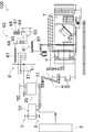
- the side view showing the whole composition of the combine concerning the embodiment of the present invention The skeleton figure which shows the structure for the power transmission of a combine.
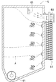
- Front sectional drawing which shows the structure of a Glen tank.
- the block diagram which shows a part of electric constitution of a combine.
- the flowchart which shows the example of acquisition control of a grain discharge time.
- the block diagram which shows the structure of the discharge auger diagnostic system of a modification.
- FIG. 1 is a side view showing an overall configuration of a combine 100 according to the embodiment of the present invention.
- FIG. 2 is a skeleton diagram showing a configuration for power transmission of the combine 100.
- FIG. 3 is a front sectional view showing the configuration of the Glen tank 5.
- FIG. 4 is a block diagram showing a part of an electrical configuration of combine 100.
- front means the direction in which the combine 100 advances when mowing
- rear means the opposite direction.
- left and right mean left and right with respect to the forward combine 100.
- the combine 100 of 1st Embodiment is the main-body part 1, the crawler device 2, the mowing device 3, the threshing device 4, the sorting device 7, and a grain tank (grain storage part). 5, the grain discharging device 6, the operating unit 16, and the engine 20.
- the main body 1 supports the engine 20 that is the drive source of the combine 100.
- the main body 1 can travel in the field by the crawler device 2.
- the crawler device 2 is provided below the main body 1.
- the crawler device 2 is configured as a traveling device including an endless crawler.
- the reaping device 3 is connected to the front part of the main body 1.
- the reaping device 3 can reaper the root of a grain culm of a crop such as rice.
- the threshing device 4 is provided on the left side of the main body 1.
- the threshing device 4 is arranged behind the harvesting device 3.
- the threshing device 4 threshes the grain culms cut by the reaping device 3.
- the sorting device 7 is provided on the left side of the main body 1.
- the sorting device 7 is arranged below the threshing device 4.
- the sorting device 7 sorts and takes out the grains that have been threshed by the threshing device 4.
- the Glen tank 5 is provided on the right rear side of the main body 1.
- the Glen tank 5 is arranged on the right side of the sorting device 7.
- the grain tank 5 stores the grains selected by the selection device 7. The detailed configuration of the Glen tank 5 will be described later.
- the grain discharging device 6 is connected to the lower side of the rear part of the Glen tank 5.
- the grain discharging device 6 can discharge the grains stored in the grain tank 5 to the outside of the grain tank 5.
- the driving unit 16 is provided on the right front side of the main body 1.
- the operation unit 16 is arranged between the harvesting device 3 and the Glen tank 5.
- the operating unit 16 is configured as a cabin, and inside thereof, a living space for an operator who operates the combine 100 is configured.
- a driver's seat 17 on which an operator sits is arranged in the driver unit 16.
- the operation unit 16 also includes an operation member (for example, a steering wheel 18) for an operator to instruct the combine 100 to run and mow.
- the control device 11 is arranged at an appropriate position of the operation unit 16. As shown in FIG. 4, the control device 11 includes a control unit 11a, a storage unit 11b, and a display unit 11c.
- the control unit 11a is configured by an arithmetic device such as a CPU or an arithmetic device such as an FPGA or an ASIC arranged in the control device 11.
- the control unit 11a reads various programs stored in the storage unit 11b into the RAM and executes the programs to perform various processes according to the operation of the operator.
- the storage unit 11b is composed of a non-volatile memory such as a flash memory, a hard disk, or an optical disk.
- the storage unit 11b stores a threshold value Tt and the like regarding the diagnosis of the maintenance time of the grain discharge auger 62.
- the display unit 11c is composed of, for example, a liquid crystal display.
- the display unit 11c displays operation information of the combine 100, maintenance information indicating maintenance time of each unit of the combine 100, and the like.
- the engine 20 is arranged below the driving unit 16.
- the engine 20 is configured as a diesel engine, for example.
- the power of the engine 20 is branched and transmitted from the output shaft 21 to the continuously variable transmission 22, the mowing device 3, the threshing device 4, and the grain discharging device 6. ..
- the continuously variable transmission 22 is configured as, for example, a static pressure hydraulic continuously variable transmission (HST). Since the continuously variable transmission 22 has a known structure including a pair of a hydraulic pump and a hydraulic motor (not shown), detailed description thereof will be omitted.
- the crawler device 2 is driven by the power changed by the continuously variable transmission device 22.
- the Glen tank 5 is used to store grains.
- the Glen tank 5 is arranged on the left side of the threshing device 4 in the left-right direction of the main body 1.
- the grain tank 5 stores the grains selected by the selection device 7.
- the grain tank 5 is provided with a harvest amount sensor (storage amount detection unit) 51 and a paddy sensor (grain detection unit) 52.
- the harvest amount sensor 51 detects the harvest amount HA, which is the amount of grains harvested with the combine 100. As shown in FIG. 3, the harvest sensor 51 is mounted so as to be suspended from the ceiling surface inside the Glen tank 5.
- the yield sensor 51 is composed of a strain gauge, a piezoelectric element, or the like, and detects an impact from the outside.
- the grain tank 5 is connected to a fried grain conveyor 81 that conveys the grains selected by the selection device 7.
- the fried grain conveyor 81 is configured as a screw conveyor, and a discharge blade 82 is provided at the end of the shaft on the downstream side in the transport direction.
- the discharge blade 82 bounces the grain conveyed by the fried grain conveyor 81 toward the grain tank 5.
- the harvest amount sensor 51 detects the impact force caused by the impact of the grains bounced off by the discharge blade 82, and outputs the impact force to the control device 11.
- the control unit 11a included in the control device 11 calculates the harvest amount HA of the harvested grains based on the detection result input from the harvest sensor 51. That is, it can be said that the larger the impact force detected by the harvest sensor 51, the larger the amount of grains supplied from the fried grain conveyor 81 to the grain tank 5 per unit time.
- the control unit 11a estimates the grain input amount per unit time to the grain tank 5 based on the detection result of the harvest sensor 51, and obtains the harvest amount HA by accumulating this.
- the harvest amount HA calculated by the control unit 11a is stored in the storage unit 11b.
- This harvest amount HA is the combine harvester from the time when all the grains in the grain tank 5 are discharged through the grain discharging device 6 (that is, the grain is not stored in the grain tank 5) to the present.
- the total amount of grains supplied to the Glen tank 5 by operation 100 is shown.
- the paddy sensor 52 detects the accumulated amount (and thus the accumulated amount) of the grains stored inside the Glen tank 5. Strictly speaking, the paddy sensor 52 detects the height of the upper surface of the grain (grain puddle) stored inside the grain tank 5 step by step.
- a plurality of paddy sensors 52 (five in the present embodiment) are arranged side by side in the vertical direction at a predetermined interval. Each paddy sensor 52 is attached to the inner wall of the Glen tank 5. Each paddy sensor 52 can substantially detect whether the upper surface of the grain reservoir is above or below the height of the paddy sensor 52.
- the first paddy sensor (first grain detection unit) 52a and the second paddy sensor (second grain) in order from the lowermost side.
- the paddy sensor 52 is composed of, for example, a push switch.
- the plurality of paddy sensors 52 are sequentially pressed from the lower side as the grain is stored in the grain tank 5.
- the paddy sensor 52 pressed by the grain outputs a detection signal to the control device 11.
- the paddy sensor 52 when the paddy sensor 52 is pressed by the grain stored in the grain tank 5, the paddy sensor 52 is turned on. On the other hand, when the paddy sensor 52 is not pressed by the grain, the paddy sensor 52 is turned off. However, ON/OFF may be reversed.
- the control device 11 can estimate the storage amount of the grain stored in the grain tank 5. Then, the control device 11 can estimate the storage rate of the grain based on the time difference between the two adjacent paddy sensors 52 being turned on. As a result, the control device 11 can predict the time when the Glen tank 5 will be full, for example, and display it on the display unit 11c.
- the fourth paddy sensor 52d provided second from the top is provided at a position corresponding to the full amount of the Glen tank 5.
- the control device 11 of FIG. 4 causes the display unit 11c to display that the amount is full.
- the fourth paddy sensor 52d is arranged at a height that secures an appropriate margin with respect to the physical storage limit of the Glen tank 5. As a result, it is possible to secure a storage space for the grains to be harvested after the display unit 11c displays that the amount is full and until the harvesting device 3 and the threshing device 4 are stopped.
- the fifth paddy sensor 52e arranged at the top is provided to prevent a failure.
- the control device 11 automatically stops the harvesting device 3 and the threshing device 4. This makes it possible to avoid damage to the device due to excessive storage of grains.
- the grain discharging device 6 is used to discharge the grains stored in the grain tank 5 to the outside.
- the grain discharge device 6 includes a bottom conveyor 61 and a grain discharge auger (discharge unit) 62.
- the bottom conveyor 61 is arranged at the bottom of the Glen tank 5, as shown in FIG.
- the bottom conveyor 61 is composed of a screw that rotates around an axis extending in the front-rear direction of the main body 1.
- the bottom conveyor 61 is rotationally driven by the driving force from the engine 20, as shown in FIG.
- the bottom conveyor 61 conveys the grain stored in the Glen tank 5 backward.
- an auger clutch 91 is arranged in the drive transmission path between the bottom conveyor 61 and the engine 20.
- the auger clutch 91 is configured as a belt tension clutch that switches between a state in which tension is applied to the transmission belt and a state in which tension is not applied.
- the auger clutch 91 switches transmission/interruption of the driving force of the engine 20 to the bottom conveyor 61.
- the grain discharge auger 62 is used to discharge the grain conveyed by the bottom conveyor 61 to the outside.
- the grain discharging auger 62 includes a vertical discharging auger 63 and a horizontal discharging auger 64.
- the vertical discharge auger 63 is arranged behind the Glen tank 5 and extends vertically.
- the vertical discharge auger 63 includes a vertical discharge auger cylinder 65 and a vertical discharge conveyor 66.
- the vertical discharge auger cylinder 65 is composed of, for example, a circular tubular member.
- a vertical discharge conveyor 66 is built in the vertical discharge auger cylinder 65.
- the vertical discharge conveyor 66 is composed of a screw that rotates around an axis extending in the vertical direction. As shown in FIG. 2, the vertical discharge conveyor 66 is connected to the bottom conveyor 61 via a bevel gear. The vertical discharge conveyor 66 is rotationally driven by the driving force transmitted via the bottom conveyor 61.
- the lateral discharge auger 64 is arranged in the upper portion of the main body 1 in the housed state shown in FIG.
- the horizontal discharge auger 64 includes a horizontal discharge auger cylinder 67 and a horizontal discharge conveyor 68.
- the lateral discharge auger cylinder 67 is composed of, for example, a circular tubular member.
- a horizontal discharge conveyor 68 is built in the horizontal discharge auger cylinder 67.
- the horizontal discharge conveyor 68 is composed of a screw that rotates around an axis extending in the front-rear direction when the horizontal discharge auger 64 is stored.
- the horizontal discharge conveyor 68 is connected to the vertical discharge conveyor 66 via a bevel gear.
- the horizontal discharge conveyor 68 is rotationally driven by the driving force transmitted via the bottom conveyor 61 and the vertical discharge conveyor 66.
- the bottom conveyor 61, the vertical discharge conveyor 66, and the horizontal discharge conveyor 68 are rotationally driven by the driving force from the engine 20, and the grains are discharged from the grain discharge auger 62. Is discharged.
- the auger clutch 91 is disengaged, the driving force from the engine 20 is cut off, and the rotation of the bottom conveyor 61, the vertical discharge conveyor 66, and the horizontal discharge conveyor 68 is stopped, so that the grain discharge by the grain discharge auger 62 is performed. Is stopped.
- the grains come into contact with the inner wall of the vertical discharge auger cylinder 65, the vertical discharge conveyor 66, the inner wall of the horizontal discharge auger cylinder 67, the horizontal discharge conveyor 68, and the like. And collide. As a result, the inner wall of the vertical discharge auger cylinder 65, the vertical discharge conveyor 66, the inner wall of the horizontal discharge auger cylinder 67, the horizontal discharge conveyor 68, and the like are gradually worn. The rate of progress of wear varies depending on the hardness of the grain, the water content, and the like.
- the gap between the vertical discharge auger cylinder 65 and the vertical discharge conveyor 66 and the gap between the horizontal discharge auger cylinder 67 and the horizontal discharge conveyor 68 gradually increase, and The discharging efficiency of the particles is lowered, and the discharging time becomes longer. Therefore, when the wear of the grain discharging auger 62 progresses to a certain degree, it is necessary to perform maintenance such as replacement of the grain discharging auger 62.
- the combine 100 includes an emission auger diagnosis system (emission section diagnosis system) 10.
- the discharge auger diagnostic system 10 can determine the degree of wear of the grain discharge auger 62 and notify the operator of the maintenance time of the grain discharge auger 62.
- the discharge auger diagnosis system 10 uses the control device 11 shown in FIG. 4 to determine whether the grain discharge auger 62 needs maintenance based on the detection results from various sensors.
- the sensors used for the determination include, for example, an engine speed sensor 12, an auger speed sensor 13, an auger clutch sensor 14, a harvest sensor 51, and a paddy sensor 52.
- the engine speed sensor 12 is used to detect the engine speed Ne.
- the configuration of the engine speed sensor 12 is arbitrary, for example, a pulse generator that generates a pulse according to the rotation of the output shaft 21 of the engine 20 can be considered.
- the engine speed sensor 12 outputs the detected engine speed Ne to the control device 11.
- the auger rotation speed sensor 13 is used to detect the auger rotation speed Na of the grain discharging auger 62.
- the auger rotation speed sensor 13 is attached to, for example, the rotation shaft of the vertical discharge conveyor 66 or the rotation shaft of the horizontal discharge conveyor 68.
- the auger rotation speed sensor 13 may have the same configuration as the engine rotation speed sensor 12 or may have a different configuration.
- the engine rotation speed sensor 12 outputs the detected auger rotation speed Na to the control device 11.
- the auger clutch sensor 14 detects the on/off state of the auger clutch 91 (that is, the state regarding connection/disconnection). The auger clutch sensor 14 outputs the detected state of the auger clutch 91 to the control device 11.
- the discharge auger diagnosis system 10 uses the detection results from the various sensors described above and discharges the grain discharge time T required to discharge the grain of the predetermined amount A and the grain of the predetermined amount A.
- the standard discharge time T0 required for the design is calculated.
- the predetermined amount A is, for example, the amount of grains corresponding to the region sandwiched by the two chain lines in FIG. 3, that is, the amount of grains stored between two adjacent paddy sensors 52. be able to. However, it is not limited to this.
- the grain discharge time T can be easily obtained by obtaining the time difference between the timing when the paddy sensor 52 located on the upper side turns from ON to OFF and the timing when the paddy sensor 52 located on the lower side turns from ON to OFF. You can
- the pressure of the grain stored in the grain tank 5 increases as it is located deeper in the grain reservoir. Therefore, for example, when a grain near the full amount is stored, the grain may be particularly strongly compacted around the first paddy sensor 52a located in a deep place. As a result, although the grains are discharged from the grain tank 5 and the height of the upper surface of the grain pool is lower than that of the first paddy sensor 52a, the grain is still around the first paddy sensor 52a. It is also possible that some grains remain. Therefore, if the first paddy sensor 52a is used to obtain the grain discharge time T, a large error may occur in the grain discharge time T.
- the discharge auger diagnostic system 10 of the present embodiment is in an empty state below the fourth paddy sensor 52d that detects the full amount among the paddy sensors 52 arranged in the vertical direction.
- the grain discharge time T is obtained by using the paddy sensor 52 (the second paddy sensor 52b and the third paddy sensor 52c) above the first paddy sensor 52a that detects the amount closest to.
- the paddy sensor 52 the second paddy sensor 52b and the third paddy sensor 52c
- FIG. 5 is a flowchart showing an example of acquisition control of the grain discharge time. It should be noted that it is assumed that the grain tank 5 stores a sufficient amount (for example, full amount) of grains at the stage when the flow of FIG. 5 starts.
- the control device 11 determines whether or not the third paddy sensor 52c is switched from ON to OFF at this moment (step S101). This determination can be performed using the current state of the third paddy sensor 52c and the immediately previous state. For example, when the third paddy sensor 52c is kept ON, the control device 11 initializes the count value of the grain discharge time T (step S102). Then, the process returns to step S101.
- step S101 When it is determined in step S101 that the third paddy sensor 52c has been switched from ON to OFF, the control device 11 determines that the auger clutch 91 is in the connected state based on the detection result from the auger clutch sensor 14. It is determined whether or not there is (step S103).
- step S104 the control device 11 increases the count value of the grain discharge time T by 1 (step S104). If it is determined in step S103 that the auger clutch 91 is in the disengaged state, the process in step S104 is skipped.
- control device 11 determines whether or not the second paddy sensor 52b is switched from ON to OFF at this moment (step S105). This determination can be performed using the current state of the second paddy sensor 52b and the immediately previous state. For example, when the second paddy sensor 52b continues to be ON, the process returns to step S103.
- steps S103 to S105 By the processing of steps S103 to S105, counting of the grain discharge time T is repeated on condition that the auger clutch 91 is connected.
- the loop of steps S103 to S105 is performed at a constant cycle.
- step S105 When it is determined in step S105 that the second paddy sensor 52b has been switched from ON to OFF, the control device 11 acquires the count value of the grain discharge time T at that time (step S106). .. The grain discharge time T can be obtained by multiplying this count value by the loop cycle of steps S103 to S105. Then, the process returns to step S101.
- the storage in the grain in the grain tank 5 and the discharge of the grain from the grain tank 5 are repeated, so that the control device 11 controls the amount corresponding to the height of the third paddy sensor 52c. It is possible to acquire the substantial time required for the grain discharging device 6 to discharge the grains until the storage amount reaches the amount corresponding to the height of the second paddy sensor 52b.
- the paddy sensor 52 used for obtaining the grain discharge time T is not limited to the second paddy sensor 52b and the third paddy sensor 52c. Immediately before discharging the grain, if at least two of the five paddy sensors 52 are ON, the timing at which two arbitrarily selected from the plurality of paddy sensors 52 that are ON are turned OFF with the discharging of the grain. It can be used to determine the grain discharge time T.
- the standard discharge time T0 is used as a criterion for determining whether or not the grain discharge time T required to discharge the predetermined amount A of grains is too long.
- a plurality of standard discharge times T0 are set in accordance with different values of the engine speed Ne and the auger speed Na, and are stored in the storage unit 11b in the form of a map, for example.
- the discharge delay time ⁇ T can be considered to indicate the degree of wear of the grain discharge auger 62.
- the discharge auger diagnosis system 10 of the present embodiment it is determined whether the discharge delay time ⁇ T is excessive (in other words, whether the grain discharge auger 62 is worn to such an extent that maintenance is required).
- the threshold value Tt for performing is set in advance.
- the threshold value Tt is set based on the engine speed Ne, the auger speed Na, and the predetermined amount A.
- a plurality of threshold values Tt are set according to the values of different engine speed Ne and auger speed Na, and are stored in the storage unit 11b in the form of a map, for example.
- the discharge auger diagnosis system 10 compares the discharge delay time ⁇ T obtained as described above with the threshold value Tt corresponding to the engine speed Ne and the auger speed Na at the time of discharging the grain, and discharges the grain. It is determined whether maintenance of the auger 62 is necessary.
- the discharge auger diagnosis system 10 causes the display unit 11c to display the diagnosis result.
- the maintenance time of the grain discharge auger 62 was determined simply based on the cumulative operation time of the grain discharge auger 62.
- the discharge auger diagnosis system 10 of the present embodiment is arranged such that the maintenance timing of the grain discharge auger 62 is adjusted according to the actual degree of wear according to the usage status of the grain discharge auger 62 of each combine 100. Can be diagnosed more accurately.
- the diagnosis can be performed every time the grain discharge time T is obtained in step S106 of FIG.
- the discharge auger diagnosis system 10 may make a diagnosis for the grain discharge auger 62 every predetermined operating time. Further, the discharge auger diagnosis system 10 may perform the next diagnosis at an operation time interval corresponding to the degree of wear of the grain discharge auger 62 determined in this diagnosis.
- the discharge auger diagnosis system 10 of the present embodiment diagnoses the grain discharge auger 62 that discharges the grain stored in the grain tank 5 that stores the grain to the outside.
- the discharge auger diagnosis system 10 has a grain discharge time T required for discharging the predetermined amount A of grains by the grain discharge auger 62 and a standard discharge time T0 required for discharging the predetermined amount A of grains. Based on this, the necessity of maintenance of the grain discharge auger 62 is determined.
- the grain tank 5 is provided with a plurality of paddy sensors 52.
- the paddy sensor 52 detects the height of the upper surface of the grain pool formed in the grain tank 5 step by step.
- another paddy sensor 52 provided below the one paddy sensor 52 is a grain.
- the time required until no grains are detected is defined as the grain discharge time T.
- the plurality of paddy sensors 52 include a first paddy sensor 52a, a second paddy sensor 52b, a third paddy sensor 52c, and a fourth paddy sensor 52d.
- the first paddy sensor 52 a is provided on the inner wall of the Glen tank 5.
- the second paddy sensor 52b is provided on the inner wall of the Glen tank 5 above the first paddy sensor 52a.
- the third paddy sensor 52c is provided on the inner wall of the Glen tank 5 above the second paddy sensor 52b.
- the fourth paddy sensor 52d is provided on the inner wall of the Glen tank 5 above the third paddy sensor 52c.
- the discharge auger diagnostic system 10 sets the time required for the second paddy sensor 52b to stop detecting the grain after the third paddy sensor 52c stops detecting the grain for the grain discharging time T.
- the standard emission time T0 is calculated according to the engine speed Ne.
- the standard discharge time T0 can also be calculated according to the auger rotation speed Na.
- the discharge auger diagnostic system 10 of the present embodiment sets the time required for discharging all the grains stored in the grain tank 5 as the grain discharge time T. That is, the discharge auger diagnostic system 10 uses the detection result of the harvest sensor 51 instead of the paddy sensor 52 when determining the maintenance time of the grain discharge auger 62.
- the predetermined amount A in the present embodiment is a new harvest detected by the harvest amount sensor 51 from after all the grains stored in the Glen tank 5 are discharged to immediately before the grains are discharged.
- the harvested amount HA of the harvested grains is HA.
- the unit emission amount ⁇ A and the unit threshold ⁇ Tt are preset based on the engine speed Ne and the auger speed Na.
- the unit emission amount ⁇ A is a design standard emission amount per unit time by the grain discharging device 6.
- the standard discharge time T0 can be obtained by dividing the harvest amount HA by the unit discharge amount ⁇ A.
- the unit threshold ⁇ Tt is a threshold value per unit time.
- the threshold value Tt can be obtained by multiplying the standard discharge time T0 by the unit threshold value ⁇ Tt.
- the discharge auger diagnosis system 10 indicates the grain discharge time T required to discharge the grain of the obtained harvest amount HA and the standard discharge time T0 required to discharge the grain of the harvest amount HA.
- the discharge delay time ⁇ T is calculated using this.
- the discharge auger diagnostic system 10 compares the calculated discharge delay time ⁇ T with the threshold value Tt obtained as described above. When the discharge delay time ⁇ T is larger than the threshold value Tt, it is determined that maintenance of the grain discharge auger 62 is necessary, and the display unit 11c displays the diagnosis result.
- the grain tank 5 is provided with the harvest amount sensor 51 that detects the amount of grain (harvest amount HA) stored in the grain tank 5. ing.
- the discharge time is defined as the time required to discharge all the grains for which the harvest amount HA has been detected by the harvest amount sensor 51.
- the discharge auger diagnosis system 10 calculates the standard discharge time T0 based on the detection result of the harvest sensor 51.
- the grain discharge time T and the standard discharge time T0 can be accurately obtained without the need for another detection unit.
- FIG. 6 is a block diagram showing a configuration of a modified discharge auger diagnosis system 10x.
- the same or similar members as those in the above-described embodiment are denoted by the same reference numerals in the drawings, and the description may be omitted.
- the management server 31 diagnoses the maintenance time of the grain discharge auger 62 instead of the combine 100.
- the control device 11 included in the combine 100 includes a communication unit 11d in addition to the above-described control unit 11a, storage unit 11b, and display unit 11c.
- the management server 31 is installed in a place different from the combine 100 (for example, a service center). As illustrated in FIG. 6, the management server 31 includes a control unit 31a, a storage unit 31b, a display unit 31c, and a communication unit 31d.
- the communication unit 31d of the management server 31 can communicate with the communication unit 11d included in the control device 11 of the combine 100.
- a WAN and an appropriate wireless communication means (for example, a mobile phone line) can be used for this communication.
- the management server 31 can acquire various kinds of information regarding the diagnosis from the control device 11 together with the identification information for specifying the combine 100.
- Examples of the information regarding the diagnosis include the grain discharge time T, the standard discharge time T0, the engine speed Ne and the auger speed Na at the time of discharging the grain, and the like.
- the management server 31 determines whether maintenance of the grain discharge auger 62 is necessary or not based on the grain discharge time T and the standard discharge time T0, similarly to the control device 11 of the first embodiment.
- the management server 31 determines that the grain discharge auger 62 of the combine 100 needs maintenance, the management server 31 notifies the control device 11 by communication.
- the control device 11 displays on the display unit 11c that maintenance is required.
- the management server 31 may notify the maintenance service person who has accessed the management server 31 using a portable information terminal or the like of the information about the combine 100 requiring maintenance.
- a method of notifying the necessity of maintenance for example, it is conceivable to display the diagnosis result, the specific information of the combine 100, and the like on a display unit (not shown) included in the mobile information terminal or the like.
- the maintenance time of the grain discharge auger 62 of the combine 100 can be centrally managed, and when maintenance is required, relevant persons can be notified in a timely manner. As a result, good after-sales service can be provided.
- the management server 31 can collect information on the combine 100 operating in various places, so that the maintenance time of the grain discharge auger 62 in each region can be analyzed, for example.
- the analysis result can be displayed on the display unit 31c of the management server 31, for example. Therefore, it is possible to provide relevant information to, for example, a maintenance service person so that maintenance can be performed early in an area where the grain discharging auger 62 is worn quickly. Therefore, it is possible to avoid a decrease in work efficiency due to a delay in maintenance of the grain discharge auger 62, and it is possible to improve service.
- the discharge time actually measured using a new grain discharge device 6 can be used.
- the grain discharge time T may be an average (for example, a moving average) obtained by measuring the discharge time obtained for each grain discharge a plurality of times. As a result, it is possible to avoid erroneous determination due to variations in discharge time.
- the standard discharge time T0 and the threshold Tt may be obtained according to the type of crop to be harvested.
- the type of crop may be determined from the crop information input by the operator, or may be determined using an appropriate sensor.
- the standard discharge time T0 may be obtained based on the detection result from the moisture sensor that detects the moisture contained in the harvested grains. This makes it possible to more accurately diagnose the maintenance timing of the grain discharge auger 62.
- the harvest amount sensor 51 is configured to detect the harvest amount, for example, by detecting the weight of the Glen tank 5 instead of the configuration that detects the harvest amount by using the impact force of the bounced grain. May be.
- the time until the weight of the grain tank 5 detected by the harvest sensor decreases by a predetermined value compared to before the discharge can be set as the grain discharge time T.
- the grain discharge time T may be the time required to discharge only a part of the grain whose amount is detected by the harvest sensor.
- the grain discharge time T may be calculated using two paddy sensors 52 that are not adjacent to each other.
- the predetermined amount A is the amount of grains stored between the two paddy sensors 52 used.
- the configuration in which the paddy sensor 52 detects the grain is not limited to the pressing sensor, and may be configured as, for example, an optical sensor that detects the grain by light.
- the auger rotation speed Na may be calculated from the engine rotation speed Ne. In this case, the auger rotation speed sensor 13 may not be provided.
- the auger clutch 91 may be composed of an electromagnetic clutch installed on a transmission shaft or the like. In this case, since the ON/OFF information of the auger clutch 91 can be obtained based on the output signal to the auger clutch 91, the auger clutch sensor 14 may not be provided.
- the discharge auger diagnosis system 10 or 10x may determine the maintenance time of the grain discharge auger 62 based on the grain discharge speed V instead of the grain discharge time T.
- the discharge auger diagnosis system 10 or 10x may estimate the predicted time until the maintenance time of the grain discharge auger 62 based on the difference between the discharge delay time ⁇ T and the threshold value Tt, and notify the operator or the maintenance service person. good.
- the maintenance timing of the bottom conveyor 61 can also be determined using the discharge auger diagnostic system 10, 10x.
- the discharge unit may have a configuration other than the auger (for example, a belt conveyor).
- the diagnostic system of this embodiment can be applied to other than combine (work vehicle, facility) and the like.
Landscapes
- Life Sciences & Earth Sciences (AREA)
- Environmental Sciences (AREA)
- Engineering & Computer Science (AREA)
- Mechanical Engineering (AREA)
- Threshing Machine Elements (AREA)
- Combines (AREA)
Abstract
排出オーガ診断システム(10)は、グレンタンクに貯留された穀粒を外部に排出する穀粒排出オーガを診断する。当該排出オーガ診断システム(10)は、穀粒排出オーガによる所定量の穀粒の排出に要した穀粒排出時間と、当該所定量の穀粒の排出に要する標準排出時間と、に基づいて穀粒排出オーガのメンテナンスの要否を判定する。
Description
本発明は、穀粒貯留部に貯留された穀粒を外部に排出する排出部を診断する診断システムに関する。
従来から、穀稈を刈り取って脱穀する収穫機としてのコンバインが知られている。特許文献1は、この種のコンバイン等の作業車両における制御装置を開示する。
特許文献1の制御装置は、記憶手段としてのEPROMを備える。EPROMには、作業車両に備わる機器や部品毎のメンテナンス時期が記憶される。制御装置は、稼動積算時間が各機器や部品毎に前記メンテナンス時期に達すると、電源投入時、液晶パネルにメンテナンスの実施を促す表示を行うように制御する構成となっている。
コンバインは、穀粒排出オーガ等の装置から構成された排出部を備えるが、この排出部も、使用に伴って摩耗する。排出部の摩耗の進行は、搬送する穀粒に含まれる水分の多少(水分量)等によって異なる。上記特許文献1における単に稼動積算時間に基づいてメンテナンスの要否を判定する構成は、排出部の実際の摩耗程度を反映できず、メンテナンスの時期を正確に表示できないという点で改善の余地があった。
本発明は以上の事情に鑑みてされたものであり、その目的は、穀粒の排出部に関して、現実の摩耗の程度を反映でき、メンテナンス時期を正確に診断できる排出部診断システムを提供することにある。
本発明の解決しようとする課題は以上の如くであり、次にこの課題を解決するための手段とその効果を説明する。
本発明の観点によれば、以下の構成の排出部診断システムが提供される。即ち、この排出部診断システムは、コンバインの穀粒貯留部に貯留された穀粒を外部に排出する排出部を診断する。当該排出部診断システムは、前記排出部による所定量の前記穀粒の排出に要した排出時間と、当該所定量の前記穀粒の排出に要する標準排出時間と、に基づいて、前記排出部のメンテナンスの要否を判定する。
これにより、排出部の現実の摩耗の程度を反映させて、排出部のメンテナンス時期の判定を高精度で行うことができる。
前記の排出部診断システムにおいては、以下の構成とすることが好ましい。即ち、前記穀粒貯留部には、当該穀粒貯留部内に形成される穀粒溜まりの上面の高さを段階的に検出するための複数の穀粒検出部が設けられている。前記排出部診断システムは、前記複数の穀粒検出部のうち、一の穀粒検出部が前記穀粒を検出しなくなってから、前記一の穀粒検出部より下側に設けられた他の穀粒検出部が前記穀粒を検出しなくなるまでに要した時間を、前記排出時間とする。
これにより、排出時間を容易かつ正確に求めることができる。
前記の排出部診断システムにおいては、以下の構成とすることが好ましい。即ち、前記複数の穀粒検出部は、第1穀粒検出部と、第2穀粒検出部と、第3穀粒検出部と、第4穀粒検出部と、を含む。前記第1穀粒検出部は、前記穀粒貯留部の内壁に設けられる。前記第2穀粒検出部は、前記第1穀粒検出部より上側の前記穀粒貯留部の前記内壁に設けられる。前記第3穀粒検出部は、前記第2穀粒検出部より上側の前記穀粒貯留部の前記内壁に設けられる。前記第4穀粒検出部は、前記第3穀粒検出部より上側の前記穀粒貯留部の前記内壁に設けられる。前記排出部診断システムは、前記第3穀粒検出部が前記穀粒を検出しなくなってから、前記第2穀粒検出部が前記穀粒を検出しなくなるまでに要した時間を、前記排出時間とする。
これにより、穀粒排出時間を求める機会を多く確保することができる。また、穀粒排出時間を正確に求めることができる。
前記の排出部診断システムにおいては、以下の構成とすることが好ましい。即ち、前記穀粒貯留部には、貯留量検出部が設けられている。前記貯留量検出部は、当該穀粒貯留部に貯留された前記穀粒の量を検出する。この排出部診断システムは、前記貯留量検出部により量が検出された前記穀粒の少なくとも一部を排出するのに要した時間を前記排出時間とする。当該排出部診断システムは、前記貯留量検出部の検出結果に基づいて前記標準排出時間を算出する。
これにより、他の検出部を要せずに、排出時間及び設定標準排出時間を正確に求めることができる。
前記の排出部診断システムにおいては、前記標準排出時間は、エンジン回転数に応じて算出されることが好ましい。
これにより、エンジン回転数による穀粒の排出速度への影響を考慮でき、標準排出時間を一層正確に算出することができる。
前記の排出部診断システムにおいては、以下の構成とすることが好ましい。即ち、前記排出部は、スクリューを回転させて穀粒を搬送するオーガを備える。前記標準排出時間は、オーガ回転数に応じて算出される。
これにより、オーガ回転数による穀粒の排出速度への影響を考慮でき、標準排出時間を一層正確に算出することができる。
次に、図面を参照して本発明の実施の形態を説明する。図1は、本発明の実施形態に係るコンバイン100の全体的な構成を示す側面図である。図2は、コンバイン100の動力伝達のための構成を示すスケルトン図である。図3は、グレンタンク5の構成を示す正面断面図である。図4は、コンバイン100の電気的構成の一部を示すブロック図である。
以下の説明で「前」とは、コンバイン100が刈取り時に進行する方向を意味し、「後」とは、その反対の方向を意味する。また、「左」及び「右」とは、前進するコンバイン100を基準とした左及び右を意味する。
図1等に示すように、第1実施形態のコンバイン100は、本体部1と、クローラ装置2と、刈取装置3と、脱穀装置4と、選別装置7と、グレンタンク(穀粒貯留部)5と、穀粒排出装置6と、運転部16と、エンジン20と、を備える。
本体部1は、コンバイン100の駆動源であるエンジン20を支持する。本体部1は、クローラ装置2によって圃場を走行することができる。
クローラ装置2は、本体部1の下部に設けられている。クローラ装置2は、無端状のクローラを備えた走行装置として構成されている。
刈取装置3は、本体部1の前部に接続されている。刈取装置3は、米等の作物の穀稈の株元を刈り取ることができる。
脱穀装置4は、本体部1の左部に設けられている。脱穀装置4は、刈取装置3の後方に配置されている。脱穀装置4は、刈取装置3で刈り取った穀稈を脱穀する。
選別装置7は、本体部1の左部に設けられている。選別装置7は、脱穀装置4の下方に配置されている。選別装置7は、脱穀装置4で脱穀された穀粒を選別して取り出す。
グレンタンク5は、本体部1の右部後側に設けられている。グレンタンク5は、選別装置7の右側方に配置されている。グレンタンク5は、選別装置7で選別された穀粒を貯留する。グレンタンク5の詳細な構成は後述する。
穀粒排出装置6は、グレンタンク5の後部の下側に接続されている。穀粒排出装置6は、グレンタンク5に貯留された穀粒を当該グレンタンク5の外部に排出することができる。
運転部16は、本体部1の右部前側に設けられている。運転部16は、刈取装置3とグレンタンク5との間に配置されている。運転部16はキャビンとして構成され、その内部には、コンバイン100を運転するオペレータの居住空間が構成されている。
運転部16には、オペレータが座る運転座席17が配置される。また、運転部16は、コンバイン100の走行及び刈取作業等をオペレータが指示するための操作部材(例えば、ステアリングホイール18)を備える。
運転部16の適宜位置には、制御装置11が配置されている。制御装置11は、図4に示すように、制御部11aと、記憶部11bと、表示部11cと、を備える。
制御部11aは、制御装置11内に配置されたCPU等の演算装置、又はFPGA、ASIC等の演算装置から構成される。制御部11aは、記憶部11bに記憶されたプログラムをRAMに読み出して実行することで、オペレータの操作等に応じて様々な処理を行う。
記憶部11bは、フラッシュメモリ、ハードディスク、又は光ディスク等の不揮発性メモリから構成されている。記憶部11bは、穀粒排出オーガ62のメンテナンス時期の診断に関する閾値Tt等を記憶している。
表示部11cは、例えば液晶ディスプレイから構成される。表示部11cは、コンバイン100の運転情報や、コンバイン100各部のメンテナンス時期を示すメンテナンス情報等を表示する。
エンジン20は、運転部16の下方に配置される。このエンジン20は、例えばディーゼルエンジンとして構成されている。
エンジン20の動力は、図2に示すように、出力軸21から、無段変速装置22と、刈取装置3と、脱穀装置4と、穀粒排出装置6と、にそれぞれ分岐して伝達される。
無段変速装置22は、例えば、静圧油圧式無段変速式の変速装置(HST)として構成されている。この無段変速装置22は、図略の油圧ポンプと油圧モータの対を備えた公知の構造であるため、詳細な説明は省略する。無段変速装置22によって変速された動力によって、クローラ装置2が駆動される。
次に、グレンタンク5の構成について、図3等を参照して詳細に説明する。
グレンタンク5は、穀粒を貯留するために用いられる。グレンタンク5は、本体部1の左右方向において、脱穀装置4の左側に配置されている。グレンタンク5は、選別装置7で選別された穀粒を貯留する。グレンタンク5には、収穫量センサ(貯留量検出部)51と、籾センサ(穀粒検出部)52と、が設けられている。
収穫量センサ51は、コンバイン100で収穫された穀粒の量である収穫量HAを検出する。収穫量センサ51は、図3に示すように、グレンタンク5の内部の天井面から吊り下げるように取り付けられている。収穫量センサ51は、歪みゲージ又は圧電素子等から構成され、外部からの衝撃を検出する。
図3に示すように、グレンタンク5には、選別装置7で選別された穀粒を搬送する揚穀コンベア81が接続されている。揚穀コンベア81はスクリューコンベアとして構成され、この軸の搬送方向下流側の端部には、放出羽根82が設けられている。放出羽根82は、揚穀コンベア81により搬送された穀粒をグレンタンク5に向けて跳ね飛ばす。収穫量センサ51は、放出羽根82により跳ね飛ばされた穀粒が当たることによる衝撃力を検出して、制御装置11へ出力する。
制御装置11が備える制御部11aは、収穫量センサ51から入力された検出結果に基づいて、収穫された穀粒の収穫量HAを算出する。即ち、収穫量センサ51が検出した衝撃力が大きい程、揚穀コンベア81から単位時間当たりにグレンタンク5に供給される穀粒量が多いということができる。制御部11aは、収穫量センサ51の検出結果に基づいて、グレンタンク5への単位時間当たりの穀粒投入量を推定し、これを累積することで収穫量HAを求める。制御部11aで算出された収穫量HAは、記憶部11bに記憶される。この収穫量HAは、穀粒排出装置6を介してグレンタンク5の全ての穀粒を排出した時点(即ち、グレンタンク5内に穀粒が貯留されていない状態)から、現在までに、コンバイン100の作業によってグレンタンク5に供給された穀粒の総量を示す。
籾センサ52は、グレンタンク5の内部に貯留された穀粒の堆積量(ひいては貯留量)を検出する。厳密に言えば、籾センサ52は、グレンタンク5の内部に貯留されている穀粒(穀粒溜まり)の上面の高さを、段階的に検出する。籾センサ52は、所定間隔をあけて上下方向に並べて複数(本実施形態においては5つ)設けられている。それぞれの籾センサ52は、グレンタンク5の内壁に取り付けられている。それぞれの籾センサ52は、穀粒溜まりの上面が当該籾センサ52の高さよりも上にあるか下にあるかを実質的に検出することができる。
なお、以下の説明においては、複数の籾センサ52のそれぞれを特定するために、最も下側から順に、第1籾センサ(第1穀粒検出部)52a、第2籾センサ(第2穀粒検出部)52b、第3籾センサ(第3穀粒検出部)52c、第4籾センサ(第4穀粒検出部)52d、第5籾センサ52eと呼ぶことがある。
籾センサ52は、例えば、押圧式スイッチから構成される。当該複数の籾センサ52は、グレンタンク5に穀粒が貯留されるに従って、下側から順に押圧される。穀粒により押圧された籾センサ52は、検出信号を制御装置11へ出力する。
本実施形態では、籾センサ52がグレンタンク5内に貯留された穀粒により押圧されたとき、当該籾センサ52はONとなる。一方、籾センサ52が穀粒により押圧されていないとき、当該籾センサ52はOFFとなる。ただし、ON/OFFが逆になっても良い。
それぞれの籾センサ52のON/OFF状態に基づいて、制御装置11は、グレンタンク5内に貯留されている穀粒の貯留量を推定することができる。そして、制御装置11は、隣接する2つの籾センサ52がONとなる時間差に基づいて、穀粒の貯留速度等を推定することができる。これにより、制御装置11は、例えば、グレンタンク5が満量となる時間等を予測して、表示部11cに表示することができる。
本実施形態のコンバイン100において、上から2番目に設けられた第4籾センサ52dは、グレンタンク5の満量に相当する位置に設けられている。図4の制御装置11は、第4籾センサ52dがONになると、満量であることを表示部11cに表示させる。第4籾センサ52dは、グレンタンク5の物理的な貯留限界に対して適宜のマージンを確保した高さに配置されている。これにより、満量である旨が表示部11cに表示されてから、刈取装置3及び脱穀装置4が停止されるまで、収穫される穀粒の貯留空間を確保することができる。
最も上に配置された第5籾センサ52eは、故障を防止するために設けられている。制御装置11は、第5籾センサ52eがONになると、刈取装置3及び脱穀装置4を自動的に停止させる。これにより、穀粒を貯留し過ぎることによる装置の破損を回避することができる。
穀粒排出装置6は、グレンタンク5内に貯留されている穀粒を外部へ排出するために用いられる。穀粒排出装置6は、底コンベア61と、穀粒排出オーガ(排出部)62と、を備える。
底コンベア61は、図3に示すように、グレンタンク5の底部に配置されている。底コンベア61は、本体部1の前後方向に延びる軸まわりに回転するスクリューから構成されている。底コンベア61は、図2に示すように、エンジン20からの駆動力によって回転駆動される。底コンベア61は、グレンタンク5内に貯留されている穀粒を後方へ搬送する。
底コンベア61とエンジン20との間の駆動伝達経路には、図2に示すように、オーガクラッチ91が配置されている。オーガクラッチ91は、伝動ベルトにテンションを付与する状態と付与しない状態とを切り替えるベルトテンションクラッチとして構成されている。オーガクラッチ91は、底コンベア61に対するエンジン20の駆動力の伝達/遮断を切り換える。
穀粒排出オーガ62は、底コンベア61により搬送された穀粒を外部へ排出するために用いられる。穀粒排出オーガ62は、縦排出オーガ63と、横排出オーガ64と、から構成されている。
縦排出オーガ63は、グレンタンク5の後方であって、上下方向に延びるように配置されている。縦排出オーガ63は、縦排出オーガ筒65と、縦排出コンベア66と、を備える。
縦排出オーガ筒65は、例えば、円管状部材から構成されている。縦排出オーガ筒65の内部には、縦排出コンベア66が内蔵されている。
縦排出コンベア66は、上下方向に延びる軸まわりに回転するスクリューから構成されている。縦排出コンベア66は、図2に示すように、ベベルギアを介して底コンベア61に連結されている。縦排出コンベア66は、底コンベア61を介して伝達された駆動力によって回転駆動される。
横排出オーガ64は、図1に示す収納状態において、本体部1の上部であって、略前後方向に延びるように配置されている。横排出オーガ64は、横排出オーガ筒67と、横排出コンベア68と、を備える。
横排出オーガ筒67は、例えば、円管状部材から構成されている。横排出オーガ筒67の内部には、横排出コンベア68が内蔵されている。
横排出コンベア68は、横排出オーガ64の収納状態において略前後方向に延びる軸まわりに回転するスクリューから構成されている。横排出コンベア68は、ベベルギアを介して縦排出コンベア66に連結されている。横排出コンベア68は、底コンベア61及び縦排出コンベア66を介して伝達された駆動力によって回転駆動される。
上記の構成により、オーガクラッチ91が接続された状態において、エンジン20からの駆動力によって、底コンベア61、縦排出コンベア66及び横排出コンベア68が回転駆動され、穀粒排出オーガ62から穀粒が排出される。オーガクラッチ91が切断された状態において、エンジン20からの駆動力が遮断され、底コンベア61、縦排出コンベア66及び横排出コンベア68の回転が停止するので、穀粒排出オーガ62による穀粒の排出が停止される。
穀粒排出装置6によって穀粒が搬送されるのに伴い、穀粒が、縦排出オーガ筒65の内壁、縦排出コンベア66、横排出オーガ筒67の内壁、横排出コンベア68等に対して接触及び衝突する。これにより、縦排出オーガ筒65の内壁、縦排出コンベア66、横排出オーガ筒67の内壁、横排出コンベア68等が徐々に摩耗する。摩耗の進行速度は、穀粒の硬さ、水分量等に応じて様々に異なる。
穀粒排出オーガ62における摩耗の進行によって、縦排出オーガ筒65と縦排出コンベア66との間の隙間、及び横排出オーガ筒67と横排出コンベア68との間の隙間が徐々に大きくなり、穀粒の排出効率が低下して、排出時間が長くなる。従って、穀粒排出オーガ62の摩耗が一定程度進行した場合には、穀粒排出オーガ62の交換等のメンテナンスを行う必要がある。
本実施形態のコンバイン100は、排出オーガ診断システム(排出部診断システム)10を備える。排出オーガ診断システム10は、穀粒排出オーガ62の摩耗の程度を判定し、穀粒排出オーガ62のメンテナンス時期をオペレータに知らせることができる。
排出オーガ診断システム10は、図4に示す制御装置11を用いて、様々なセンサからの検出結果に基づいて、穀粒排出オーガ62におけるメンテナンスの要否を判定している。
判定に用いられるセンサは、例えば、エンジン回転数センサ12と、オーガ回転数センサ13と、オーガクラッチセンサ14と、収穫量センサ51と、籾センサ52と、を含む。
エンジン回転数センサ12は、エンジン回転数Neを検出するために用いられる。エンジン回転数センサ12の構成は任意であるが、例えば、エンジン20の出力軸21の回転に応じてパルスを発生するパルス発生装置とすることが考えられる。エンジン回転数センサ12は、検出したエンジン回転数Neを制御装置11へ出力する。
オーガ回転数センサ13は、穀粒排出オーガ62のオーガ回転数Naを検出するために用いられる。オーガ回転数センサ13は、例えば縦排出コンベア66の回転軸又は横排出コンベア68の回転軸に取り付けられている。オーガ回転数センサ13は、エンジン回転数センサ12と同じ構成としても良いし、異なる構成としても良い。エンジン回転数センサ12は、検出したオーガ回転数Naを制御装置11へ出力する。
オーガクラッチセンサ14は、オーガクラッチ91の入り切り状態(即ち、接続/切断に関する状態)を検出するものである。オーガクラッチセンサ14は、検出したオーガクラッチ91の状態を制御装置11へ出力する。
排出オーガ診断システム10は、上記の様々なセンサからの検出結果を用いて、所定量Aの穀粒を排出するために要した穀粒排出時間Tと、当該所定量Aの穀粒を排出するために要する設計上の標準排出時間T0と、を求める。
当該所定量Aは、例えば、図3の2つの鎖線に挟まれた領域に相当する穀粒の量、即ち、互いに隣接する2つの籾センサ52の間に貯留されている穀粒の量とすることができる。しかし、これに限定されない。
穀粒がグレンタンク5の底部から排出されるのに伴って、穀粒溜まりの上面の高さが徐々に低下していく。上側に位置する籾センサ52がONからOFFとなるタイミングと、下側に位置する籾センサ52がONからOFFとなるタイミングと、の時間差を求めることで、穀粒排出時間Tを容易に得ることができる。
ところで、コンバイン100が刈取りを行ってグレンタンク5に貯留される収穫量HAが満量に達する前に、グレンタンク5からの穀粒を排出する場合は少なくない。従って、穀粒排出時間Tを求めるために仮に第4籾センサ52dを用いる場合、穀粒排出装置6による排出を行っているにもかかわらず穀粒排出時間Tを求めることができない状況が頻繁に発生する。
また、グレンタンク5に貯留される穀粒の圧力は、穀粒溜まりの深い部分に位置する程大きくなる。従って、例えば満量近くの穀粒を貯留した場合、深い場所に位置する第1籾センサ52aの周囲において、穀粒が特に強く押し固められることがある。この結果、グレンタンク5からの穀粒の排出が進んで、穀粒溜まりの上面の高さが第1籾センサ52aよりも低くなっているにもかかわらず、第1籾センサ52aの周囲に一部の穀粒が留まる場合も考えられる。従って、穀粒排出時間Tを求めるために仮に第1籾センサ52aを用いる場合、穀粒排出時間Tに大きな誤差が発生するおそれがある。
上記の事情を考慮して、本実施形態の排出オーガ診断システム10は、上下方向に並べられる籾センサ52のうち、満量を検出する第4籾センサ52dよりも下で、かつ、空の状態に最も近い量を検出する第1籾センサ52aよりも上の籾センサ52(第2籾センサ52b及び第3籾センサ52c)を用いて、穀粒排出時間Tを求めている。これにより、穀粒排出時間Tを取得する機会を多く確保するとともに、穀粒排出時間Tの取得精度を高めることができる。この結果、穀粒排出オーガ62のメンテナンス時期の判定をより正確に行うことができる。
次に、図5を参照して、制御装置11において穀粒排出時間Tを求める処理を詳細に説明する。図5は、穀粒排出時間の取得制御の例を示すフローチャートである。なお、図5のフローがスタートする段階で、グレンタンク5には穀粒が十分な量(例えば、満量)貯留されているものとする。
図5のフローがスタートすると、制御装置11は、この瞬間に、第3籾センサ52cがONからOFFに切り替わったか否かを判定する(ステップS101)。この判定は、第3籾センサ52cの現在の状態と、直前の状態と、を用いて行うことができる。例えば第3籾センサ52cがONを継続している場合は、制御装置11は、穀粒排出時間Tのカウント値を初期化する(ステップS102)。その後、処理はステップS101に戻る。
ステップS101の判断で、第3籾センサ52cのONからOFFへの切り替わりがあったと判定した場合は、制御装置11は、オーガクラッチセンサ14からの検出結果に基づいて、オーガクラッチ91が接続状態であるか否かを判定する(ステップS103)。
ステップS103の判断で、オーガクラッチ91が接続状態である場合は、制御装置11は、穀粒排出時間Tのカウント値を1だけ増加させる(ステップS104)。ステップS103の判断で、オーガクラッチ91が切断状態である場合は、ステップS104の処理はスキップされる。
その後、制御装置11は、この瞬間に、第2籾センサ52bがONからOFFに切り替わったか否かを判定する(ステップS105)。この判定は、第2籾センサ52bの現在の状態と、直前の状態と、を用いて行うことができる。例えば第2籾センサ52bがONを継続している場合は、処理はステップS103に戻る。
ステップS103~ステップS105の処理により、オーガクラッチ91の接続を条件として、穀粒排出時間Tのカウントが繰り返される。ステップS103~ステップS105のループは、一定の周期で行われる。
ステップS105の判断で、第2籾センサ52bのONからOFFへの切り替わりがあったと判定した場合は、制御装置11は、その時点での穀粒排出時間Tのカウント値を取得する(ステップS106)。このカウント値に、上記のステップS103~ステップS105のループ周期を乗じることにより、穀粒排出時間Tを求めることができる。その後、処理はステップS101に戻る。
以上の処理により、グレンタンク5への穀粒への貯留、グレンタンク5からの穀粒の排出が繰り返されるのに応じて、制御装置11は、第3籾センサ52cの高さに相当する量から第2籾センサ52bの高さに相当する量に貯留量が至るまで、穀粒排出装置6によって穀粒が排出されるのに要した実質的な時間を取得することができる。
穀粒排出時間Tを求めるために用いる籾センサ52は、第2籾センサ52b及び第3籾センサ52cに限定されない。穀粒を排出する直前において、5つの籾センサ52のうち少なくとも2つがONであれば、ONである複数の籾センサ52から任意に選択された2つが穀粒排出に伴ってOFFになるタイミングを用いて、穀粒排出時間Tを求めることができる。
標準排出時間T0は、所定量Aの穀粒の排出に要した穀粒排出時間Tが長過ぎるか否かを判定する基準として用いられる。標準排出時間T0は、異なるエンジン回転数Ne及びオーガ回転数Naの値に応じて複数設定され、例えばマップの形で記憶部11bに記憶される。
次に、排出オーガ診断システム10は、求められた穀粒排出時間Tと、標準排出時間T0と、を比較し、当該穀粒排出時間Tと標準排出時間T0との時間差である排出遅延時間ΔT(即ち、ΔT=T-T0)を求める。排出遅延時間ΔTは、穀粒排出オーガ62の摩耗の程度を示していると考えることができる。
本実施形態の排出オーガ診断システム10においては、排出遅延時間ΔTが過大であるか否か(言い換えれば、穀粒排出オーガ62のメンテナンスが必要な程度まで摩耗が進行しているか否か)を判断するための閾値Ttが予め設定されている。
当該閾値Ttは、エンジン回転数Ne及びオーガ回転数Naと、上記所定量Aと、に基づいて設定される。閾値Ttは、異なるエンジン回転数Ne及びオーガ回転数Naの値に応じて複数設定され、例えばマップの形で記憶部11bに記憶される。
排出オーガ診断システム10は、上記のように求められた排出遅延時間ΔTと、穀粒を排出する際におけるエンジン回転数Ne及びオーガ回転数Naに対応する閾値Ttと、を比較し、穀粒排出オーガ62のメンテナンスの要否を判定する。
具体的には、ΔTが閾値Tt以下である場合、穀粒排出オーガ62のメンテナンスが必要ではないと判定し、排出遅延時間ΔTが閾値Ttより大きい場合、穀粒排出オーガ62のメンテナンスが必要であると判定する。穀粒排出オーガ62のメンテナンスが必要と判定された場合、排出オーガ診断システム10は、当該診断結果を表示部11cに表示させる。
上述したように、従来は、単に穀粒排出オーガ62の稼動累積時間に基づいて、穀粒排出オーガ62のメンテナンス時期を判定していた。これに比べて、本実施形態の排出オーガ診断システム10は、それぞれのコンバイン100の穀粒排出オーガ62の使用状況に応じた現実の摩耗の程度に即して、穀粒排出オーガ62のメンテナンス時期に対する診断をより正確に行うことができる。
診断は、図5のステップS106で穀粒排出時間Tが求められる毎に行うことができる。ただし、排出オーガ診断システム10は、穀粒排出オーガ62に対する所定稼動時間毎に診断を行っても良い。また、排出オーガ診断システム10は、今回の診断で判定された穀粒排出オーガ62の摩耗程度に応じた稼動時間間隔で、次回の診断を行っても良い。
以上に説明したように、本実施形態の排出オーガ診断システム10は、穀粒を貯留するグレンタンク5に貯留された穀粒を外部に排出する穀粒排出オーガ62を診断する。当該排出オーガ診断システム10は、穀粒排出オーガ62による所定量Aの穀粒の排出に要した穀粒排出時間Tと、当該所定量Aの穀粒の排出に要する標準排出時間T0と、に基づいて、穀粒排出オーガ62のメンテナンスの要否を判定する。
これにより、穀粒排出オーガ62の現実の摩耗の程度を反映させて、穀粒排出オーガ62のメンテナンス時期の判定を高精度で行うことができる。
また、本実施形態の排出オーガ診断システム10において、グレンタンク5には、複数の籾センサ52が設けられている。籾センサ52は、グレンタンク5内に形成される穀粒溜まりの上面の高さを段階的に検出する。排出オーガ診断システム10は、複数の籾センサ52のうち、一の籾センサ52が穀粒を検出しなくなってから、当該一の籾センサ52より下側に設けられた他の籾センサ52が穀粒を検出しなくなるまでに要した時間を、穀粒排出時間Tとする。
これにより、穀粒排出時間Tを容易かつ正確に求めることができる。
また、本実施形態の排出オーガ診断システム10において、複数の籾センサ52は、第1籾センサ52aと、第2籾センサ52bと、第3籾センサ52cと、第4籾センサ52dと、を含む。第1籾センサ52aは、グレンタンク5の内壁に設けられる。第2籾センサ52bは、第1籾センサ52aより上側のグレンタンク5の内壁に設けられる。第3籾センサ52cは、第2籾センサ52bより上側のグレンタンク5の内壁に設けられる。第4籾センサ52dは、第3籾センサ52cより上側のグレンタンク5の内壁に設けられる。排出オーガ診断システム10は、第3籾センサ52cが穀粒を検出しなくなってから、第2籾センサ52bが穀粒を検出しなくなるまでに要した時間を、穀粒排出時間Tとする。
これにより、穀粒排出時間Tを求める機会を多く確保することができる。また、穀粒排出時間Tを正確に求めることができる。
また、本実施形態の排出オーガ診断システム10において、標準排出時間T0は、エンジン回転数Neに応じて算出される。
ただし、標準排出時間T0は、オーガ回転数Naに応じて算出することもできる。
これにより、エンジン回転数Ne又はオーガ回転数Naによる穀粒の排出速度への影響を考慮でき、標準排出時間T0を一層正確に算出することができる。
次に、第2実施形態を説明する。なお、本実施形態の説明においては、前述の実施形態と同一又は類似の内容について説明を省略する場合がある。
本実施形態の排出オーガ診断システム10は、グレンタンク5内に貯留された穀粒の全てを排出するのに要した時間を穀粒排出時間Tとする。即ち、排出オーガ診断システム10は、穀粒排出オーガ62のメンテナンス時期を判定する際に、籾センサ52の代わりに、収穫量センサ51による検出結果を用いる。
言い換えれば、本実施形態における所定量Aは、グレンタンク5内に貯留された穀粒が全て排出された後から、穀粒を排出する直前までに、収穫量センサ51により検出された新たに収穫した穀粒の収穫量HAとなる。
本実施形態の排出オーガ診断システム10においては、エンジン回転数Ne及びオーガ回転数Naと、に基づいて、単位排出量ΔA及び単位閾値ΔTtが予め設定されている。
単位排出量ΔAとは、穀粒排出装置6による単位時間当たりの設計上の標準排出量である。収穫量HAを単位排出量ΔAで除算することで、標準排出時間T0を得ることができる。
単位閾値ΔTtとは、単位時間当たりの閾値である。標準排出時間T0に単位閾値ΔTtを乗じることで、閾値Ttを求めることができる。
排出オーガ診断システム10は、求められた収穫量HAの穀粒を排出するのに要した穀粒排出時間Tと、当該収穫量HAの穀粒を排出するのに要する標準排出時間T0と、を用いて排出遅延時間ΔTを算出する。
その後、排出オーガ診断システム10は、算出された排出遅延時間ΔTと、上記のように求められた閾値Ttと、を比較する。排出遅延時間ΔTが閾値Ttより大きい場合、穀粒排出オーガ62のメンテナンスが必要と判定し、表示部11cに当該診断結果を表示させる。
以上に説明したように、本実施形態の排出オーガ診断システム10において、グレンタンク5には、グレンタンク5に貯留された穀粒の量(収穫量HA)を検出する収穫量センサ51が設けられている。排出オーガ診断システム10では、収穫量センサ51により収穫量HAが検出された穀粒の全てを排出するのに要した時間を排出時間とする。排出オーガ診断システム10では、収穫量センサ51の検出結果に基づいて標準排出時間T0を算出する。
これにより、他の検出部を要せずに、穀粒排出時間T及び標準排出時間T0を正確に求めることができる。
次に、上記実施形態の変形例を説明する。図6は、変形例の排出オーガ診断システム10xの構成を示すブロック図である。なお、本変形例の説明においては、前述の実施形態と同一又は類似の部材には図面に同一の符号を付し、説明を省略する場合がある。
本変形例の排出オーガ診断システム10xは、穀粒排出オーガ62のメンテナンス時期を、コンバイン100の代わりに管理サーバ31が診断する。
コンバイン100が備える制御装置11は、前述の制御部11a、記憶部11b、及び表示部11cのほか、通信部11dを備える。
管理サーバ31は、コンバイン100とは異なる場所(例えば、サービスセンター等)に設置されている。管理サーバ31は、図6に示すように、制御部31aと、記憶部31bと、表示部31cと、通信部31dと、を備える。
管理サーバ31の通信部31dは、コンバイン100の制御装置11が備えた通信部11dとの間で通信を行うことができる。この通信には、WAN及び適宜の無線通信手段(例えば、携帯電話回線)を用いることができる。
この通信により、管理サーバ31は、コンバイン100を特定するための識別情報とともに、診断に関する各種の情報を制御装置11から取得することができる。診断に関する情報としては、例えば、穀粒排出時間T、標準排出時間T0、穀粒を排出する際におけるエンジン回転数Ne及びオーガ回転数Na等を挙げることができる。管理サーバ31は、第1実施形態の制御装置11と同様に、穀粒排出時間T及び標準排出時間T0に基づいて、穀粒排出オーガ62のメンテナンスの要否を判定する。
コンバイン100の穀粒排出オーガ62のメンテナンスが必要であると管理サーバ31が判定した場合、管理サーバ31は、制御装置11に対して、通信によりその旨を通知する。制御装置11は、メンテナンスが必要であること等を、表示部11cに表示する。
管理サーバ31は、当該管理サーバ31に携帯情報端末等を用いてアクセスしたメンテナンスサービス担当者等に対して、メンテナンスが必要なコンバイン100に関する情報を通知しても良い。メンテナンスの必要性を知らせる方法としては、例えば、診断結果及びコンバイン100の特定情報等を、携帯情報端末等が備える図略の表示部等に表示させることが考えられる。
本変形例の排出オーガ診断システム10xでは、コンバイン100の穀粒排出オーガ62のメンテナンス時期を集中的に管理することができ、メンテナンスが必要な場合、関係者にタイムリーに通知することができる。この結果、良いアフターサービスを提供することができる。
本変形例では、各所で稼動しているコンバイン100の情報を管理サーバ31において収集することができるので、例えば、地域毎における穀粒排出オーガ62のメンテナンス時期を分析することができる。分析結果は、例えば管理サーバ31の表示部31cに表示させることができる。従って、穀粒排出オーガ62の摩耗が早い地域に対して、メンテナンスを早い時期で行うように、例えばメンテナンスサービス担当者に関連情報を提供することができる。よって、穀粒排出オーガ62のメンテナンスの遅れによる作業効率の低下を回避することができ、サービスの向上を実現することができる。
以上に本発明の好適な実施の形態及び変形例を説明したが、上記の構成は例えば以下のように変更することができる。
標準排出時間は、設計上の排出時間を用いることに代えて、例えば、新品の穀粒排出装置6を用いて実際に測定した排出時間を用いることもできる。
穀粒排出時間Tは、穀粒の排出毎に求められた排出時間を複数回測定した平均(例えば、移動平均)とすることもできる。これにより、排出時間のバラツキによる誤判断を回避することができる。
標準排出時間T0及び閾値Tt(単位閾値ΔTt)は、収穫する作物の種類に応じて求めても良い。この場合、作物の種類は、オペレータが入力した作物の情報から判定しても良いし、適宜のセンサを用いて判定しても良い。
標準排出時間T0は、収穫された穀粒に含まれる水分を検出する水分センサからの検出結果に基づいて求めても良い。これにより、穀粒排出オーガ62のメンテナンス時期に対する診断を一層正確に行うことができる。
収穫量センサ51は、跳ね飛ばされてきた穀粒による衝撃力を用いて収穫量を検出する構成の代わりに、例えば、グレンタンク5の重量を検出することで収穫量を検出するように構成されても良い。
第2実施形態において、例えば、収穫量センサによって検出したグレンタンク5の重量が排出前と比較して所定値だけ減少するまでの時間を、穀粒排出時間Tとすることもできる。言い換えれば、穀粒排出時間Tは、収穫量センサによって量が検出された穀粒の一部だけを排出するのに要した時間としても良い。
必要に応じて、互いに隣接していない2つの籾センサ52を用いて穀粒排出時間Tを求めても良い。この場合、所定量Aは、用いられる2つの籾センサ52の間に貯留された穀粒の量となる。
籾センサ52が穀粒を検出する構成は、押圧センサに限定されず、例えば、光によって穀粒を検出する光センサとして構成しても良い。
オーガ回転数Naは、エンジン回転数Neから算出されても良い。この場合、オーガ回転数センサ13を設けなくても良い。
オーガクラッチ91は、伝動軸等に設置された電磁クラッチから構成されても良い。この場合、オーガクラッチ91への出力信号に基づいて当該オーガクラッチ91のON/OFF情報を取得することができるので、オーガクラッチセンサ14を設けなくても良い。
排出オーガ診断システム10,10xは、穀粒排出時間Tの代わりに、穀粒の排出速度Vに基づいて、穀粒排出オーガ62のメンテナンス時期を判定しても良い。
排出オーガ診断システム10,10xは、排出遅延時間ΔTと閾値Ttとの差に基づいて、穀粒排出オーガ62のメンテナンス時期までの予測時間を推定して、オペレータ又はメンテナンスサービス担当者に知らせても良い。
排出オーガ診断システム10,10xを用いて、底コンベア61のメンテナンス時期を判定することもできる。
排出部が、オーガ以外の構成(例えば、ベルトコンベア)を有する構成とすることもできる。
本実施形態の診断システムは、コンバイン以外(作業車両、施設)等に適用することもできる。
5 グレンタンク(穀粒貯留部)
10 排出オーガ診断システム(排出部診断システム)
62 穀粒排出オーガ(排出部)
A 所定量
T 穀粒排出時間(排出時間)
T0 標準排出時間
10 排出オーガ診断システム(排出部診断システム)
62 穀粒排出オーガ(排出部)
A 所定量
T 穀粒排出時間(排出時間)
T0 標準排出時間
Claims (6)
- 穀粒貯留部に貯留された穀粒を外部に排出する排出部を診断する排出部診断システムであって、
前記排出部による所定量の前記穀粒の排出に要した排出時間と、当該所定量の前記穀粒の排出に要する標準排出時間と、に基づいて、前記排出部のメンテナンスの要否を判定することを特徴とする排出部診断システム。 - 請求項1に記載の排出部診断システムであって、
前記穀粒貯留部には、当該穀粒貯留部内に形成される穀粒溜まりの上面の高さを段階的に検出するための複数の穀粒検出部が設けられており、
前記複数の穀粒検出部のうち、一の穀粒検出部が前記穀粒を検出しなくなってから、前記一の穀粒検出部より下側に設けられた他の穀粒検出部が前記穀粒を検出しなくなるまでに要した時間を、前記排出時間とすることを特徴とする排出部診断システム。 - 請求項2に記載の排出部診断システムであって、
前記複数の穀粒検出部は、
前記穀粒貯留部の内壁に設けられた第1穀粒検出部と、
前記第1穀粒検出部より上側の前記穀粒貯留部の前記内壁に設けられた第2穀粒検出部と、
前記第2穀粒検出部より上側の前記穀粒貯留部の前記内壁に設けられた第3穀粒検出部と、
前記第3穀粒検出部より上側の前記穀粒貯留部の前記内壁に設けられた第4穀粒検出部と、
を含み、
前記第3穀粒検出部が前記穀粒を検出しなくなってから、前記第2穀粒検出部が前記穀粒を検出しなくなるまでに要した時間を、前記排出時間とすることを特徴とする排出部診断システム。 - 請求項1に記載の排出部診断システムであって、
前記穀粒貯留部には、当該穀粒貯留部に貯留された前記穀粒の量を検出する貯留量検出部が設けられており、
前記貯留量検出部により量が検出された前記穀粒の少なくとも一部を排出するのに要した時間を前記排出時間とし、
前記貯留量検出部の検出結果に基づいて前記標準排出時間を算出することを特徴とする排出部診断システム。 - 請求項1に記載の排出部診断システムであって、
前記標準排出時間は、エンジン回転数に応じて算出されることを特徴とする排出部診断システム。 - 請求項1に記載の排出部診断システムであって、
前記排出部は、スクリューを回転させて穀粒を搬送するオーガを備え、
前記標準排出時間は、オーガ回転数に応じて算出されることを特徴とする排出部診断システム。
Applications Claiming Priority (2)
| Application Number | Priority Date | Filing Date | Title |
|---|---|---|---|
| JP2018-236900 | 2018-12-19 | ||
| JP2018236900A JP7045308B2 (ja) | 2018-12-19 | 2018-12-19 | 排出部診断システム |
Publications (1)
| Publication Number | Publication Date |
|---|---|
| WO2020129397A1 true WO2020129397A1 (ja) | 2020-06-25 |
Family
ID=71100246
Family Applications (1)
| Application Number | Title | Priority Date | Filing Date |
|---|---|---|---|
| PCT/JP2019/041602 Ceased WO2020129397A1 (ja) | 2018-12-19 | 2019-10-24 | 排出部診断システム |
Country Status (2)
| Country | Link |
|---|---|
| JP (1) | JP7045308B2 (ja) |
| WO (1) | WO2020129397A1 (ja) |
Cited By (1)
| Publication number | Priority date | Publication date | Assignee | Title |
|---|---|---|---|---|
| US20220348412A1 (en) * | 2021-04-30 | 2022-11-03 | Cnh Industrial America Llc | Electronically controlled viscous coupler for combine harvester |
Citations (4)
| Publication number | Priority date | Publication date | Assignee | Title |
|---|---|---|---|---|
| JPS6027625U (ja) * | 1983-07-28 | 1985-02-25 | 株式会社クボタ | 農機の安全装置 |
| JP4714456B2 (ja) * | 2004-11-17 | 2011-06-29 | ヤンマー株式会社 | コンバイン |
| JP2013066402A (ja) * | 2011-09-21 | 2013-04-18 | Kubota Corp | コンバイン |
| JP2016131528A (ja) * | 2015-01-20 | 2016-07-25 | ヤンマー株式会社 | コンバイン |
-
2018
- 2018-12-19 JP JP2018236900A patent/JP7045308B2/ja active Active
-
2019
- 2019-10-24 WO PCT/JP2019/041602 patent/WO2020129397A1/ja not_active Ceased
Patent Citations (4)
| Publication number | Priority date | Publication date | Assignee | Title |
|---|---|---|---|---|
| JPS6027625U (ja) * | 1983-07-28 | 1985-02-25 | 株式会社クボタ | 農機の安全装置 |
| JP4714456B2 (ja) * | 2004-11-17 | 2011-06-29 | ヤンマー株式会社 | コンバイン |
| JP2013066402A (ja) * | 2011-09-21 | 2013-04-18 | Kubota Corp | コンバイン |
| JP2016131528A (ja) * | 2015-01-20 | 2016-07-25 | ヤンマー株式会社 | コンバイン |
Cited By (2)
| Publication number | Priority date | Publication date | Assignee | Title |
|---|---|---|---|---|
| US20220348412A1 (en) * | 2021-04-30 | 2022-11-03 | Cnh Industrial America Llc | Electronically controlled viscous coupler for combine harvester |
| US12150412B2 (en) * | 2021-04-30 | 2024-11-26 | Cnh Industrial America Llc | Electronically controlled viscous coupler for combine harvester |
Also Published As
| Publication number | Publication date |
|---|---|
| JP7045308B2 (ja) | 2022-03-31 |
| JP2020096566A (ja) | 2020-06-25 |
Similar Documents
| Publication | Publication Date | Title |
|---|---|---|
| JP6444491B2 (ja) | コンバイン及びコンバインのための穀粒評価制御装置 | |
| US7877181B2 (en) | Scalable grain tank fill level display | |
| US9826683B2 (en) | Grain mass flow rate determination | |
| US8340862B2 (en) | Agricultural working vehicle and display unit therefor | |
| JP5980162B2 (ja) | コンバイン | |
| EP3494772A2 (en) | Predicting grain tank levels when on slopes or hills | |
| AU2017200696A1 (en) | System and method for controlled cleaning in a cane harvester | |
| KR102671689B1 (ko) | 콤바인 | |
| JP6700696B2 (ja) | コンバイン | |
| JP6451530B2 (ja) | コンバイン | |
| KR101902671B1 (ko) | 콤바인 | |
| JP2015181371A (ja) | 走行型収穫機 | |
| EP3459339B1 (en) | Operator adjustable continuous bin level measurement | |
| JP7045308B2 (ja) | 排出部診断システム | |
| JP6208538B2 (ja) | コンバイン | |
| JP2019195269A (ja) | コンバイン | |
| US20240276914A1 (en) | Method, Apparatus and System for Agricultural Vehicle Monitoring | |
| JP2019170277A (ja) | コンバイン | |
| JP6279960B2 (ja) | コンバイン | |
| JP6279965B2 (ja) | コンバイン | |
| JP2020000107A (ja) | コンバイン | |
| JP2019092451A (ja) | 収穫機 | |
| JP6208537B2 (ja) | コンバイン | |
| JP5512373B2 (ja) | コンバイン | |
| JP6692238B2 (ja) | コンバイン |
Legal Events
| Date | Code | Title | Description |
|---|---|---|---|
| 121 | Ep: the epo has been informed by wipo that ep was designated in this application |
Ref document number: 19901070 Country of ref document: EP Kind code of ref document: A1 |
|
| NENP | Non-entry into the national phase |
Ref country code: DE |
|
| 122 | Ep: pct application non-entry in european phase |
Ref document number: 19901070 Country of ref document: EP Kind code of ref document: A1 |