WO2020129308A1 - 把持装置及び把持方法 - Google Patents
把持装置及び把持方法 Download PDFInfo
- Publication number
- WO2020129308A1 WO2020129308A1 PCT/JP2019/033630 JP2019033630W WO2020129308A1 WO 2020129308 A1 WO2020129308 A1 WO 2020129308A1 JP 2019033630 W JP2019033630 W JP 2019033630W WO 2020129308 A1 WO2020129308 A1 WO 2020129308A1
- Authority
- WO
- WIPO (PCT)
- Prior art keywords
- work
- posture
- pair
- contact
- plate
- Prior art date
- Legal status (The legal status is an assumption and is not a legal conclusion. Google has not performed a legal analysis and makes no representation as to the accuracy of the status listed.)
- Ceased
Links
Images





Classifications
-
- B—PERFORMING OPERATIONS; TRANSPORTING
- B25—HAND TOOLS; PORTABLE POWER-DRIVEN TOOLS; MANIPULATORS
- B25J—MANIPULATORS; CHAMBERS PROVIDED WITH MANIPULATION DEVICES
- B25J15/00—Gripping heads and other end effectors
- B25J15/08—Gripping heads and other end effectors having finger members
Definitions
- the present invention relates to a gripping device and a gripping method for gripping a plate-shaped work (workpiece).
- a gripping device may be used to reduce the burden on humans when removing a plate-shaped work from the supply position.
- the gripping device has a pair of sandwiching pieces that can approach and separate from each other. Both sandwiching pieces are arranged facing each other on both sides in the width direction along the plate surface of the work in a state where the plate-shaped work is placed vertically, and come close to each other and contact the outer peripheral surface (plate thickness portion) of the work, It works like holding a work.
- the gripping device is an end effector attached to the robot arm, the work can be transported from the supply position to the assembly position by driving the robot arm.
- Patent Document 1 discloses a technique for controlling a robot based on information from a line sensor. If the robot can recognize the inclination of the work by using this technique, it is considered that the work can be taken out.
- the present invention has been made in view of the above-mentioned conventional circumstances, and an object thereof is to provide a gripping device and a gripping method capable of gripping a work in an appropriate posture.
- the gripping device of the present invention includes a pair of holding parts and a posture correcting part.
- the pair of sandwiching portions are arranged to face each other on both sides in the width direction along the plate surface of the work with the work in between in a state where the plate-shaped work is placed vertically, and the plate thickness portion of the work approaches each other. Abutting against and holding the work.
- the posture correcting unit is disposed between the pair of holding units in the width direction, contacts the plate surface of the work, and corrects the work in a vertical standing posture.
- the gripping method of the present invention with respect to a plate-shaped work placed vertically, on both sides in the width direction along the plate surface of the work, with the work in between, a pair of sandwiching portions are arranged to face each other, in the width direction.
- the posture correction unit is arranged between the pair of holding units and at a position away from the plate surface of the work.
- the posture correcting unit and the work are brought relatively close to each other, and the posture correcting unit is brought into contact with the plate surface of the work to set the work in a vertical standing posture.
- the pair of holding portions are moved toward each other, and the pair of holding portions are brought into contact with the plate thickness portion of the work so that the pair of holding portions hold the work.
- the gripping device of the present invention may have a second posture correcting portion that projects from the pair of holding portions in a direction approaching each other and abuts the plate surface of the work.
- the posture correcting section and the second posture correcting section have contact surfaces that contact the plate surface of the work piece in the same plane.
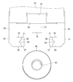
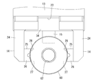
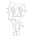
- FIG. 3 is a perspective view of the gripping device and the work in the first state as seen obliquely from below and in the front in the first embodiment. It is the perspective view which looked at a grasping device and a work in a 1st state from the slanting lower back.
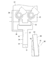
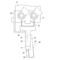
- FIG. 3 is a front view of the gripping device and the work in the first state. It is a front view of a grasping device and a work in a 2nd state. It is a front view of a grasping device and a work in a 4th state. It is a side view of a grasping device and a work in a 1st state. It is a side view of a grasping device and a work in a 2nd state.
- the first embodiment will be described based on FIGS. 1 to 10.
- the grip device 10 of the first embodiment is an end effector of an articulated robot.
- the gripping device 10 grips the work 60, conveys the work 60 by driving a robot arm, releases the grip of the work 60 at a predetermined assembly position, and sets the work 60 as an assembly target at the assembly position. To work.
- the work 60 is configured as an oil seal provided inside the hydraulic shock absorber.
- the oil seal as the work 60 is an annular base metal (base metal, metal ring) 61 and a seal lip and a dasher that are provided on the inner peripheral side of the base metal 61 and are in sliding contact with the outer periphery of the piston rod. And a lip 62 having a strip.
- a pallet case 80 which is schematically shown by a chain double-dashed line in FIGS. 6 to 10, is installed at a supply position to the gripping device 10.
- the pallet case 80 has an accommodating groove 81 capable of accommodating the work 60 vertically.
- the accommodation groove 81 opens upward in a slit shape, and a plurality of accommodation grooves 81 are provided side by side in the pallet case 80 (FIGS. 6 to 10 show only one accommodation groove 81).
- Various kinds of works 60 having different thicknesses can be housed in the housing groove 81. Therefore, the groove width of the accommodation groove 81 is set corresponding to the work having the largest thickness.
- the center of gravity is biased to the rear side (left side in FIG. 6) where the lip 62 projects, and the plate surface is inclined rearward with respect to the vertical direction (vertical direction).
- the tilted work 60 is corrected by the posture correction unit 15 described below into a posture that stands up and down.
- a gripping device 10 includes an attachment 11 attached to a terminal end of a robot arm, a housing 12, a cylinder body 13, a pair of gripping portions 14, and a posture correction.
- the unit 15 is provided. 1 and 2 show a state (first state described later) immediately before the gripping device 10 grips the work 60 supplied to the supply position.
- the vertical direction is based on FIGS. 1 and 2
- the front-back direction is the right side of FIGS. 1 and 2 as the front side.
- the housing 12 is formed in a substantially rectangular shape.
- the attachment 11 is arranged on the front side of the housing 12, and the cylinder body 13 is arranged on the lower side of the housing 12.
- the attachment 11 has a columnar shape and is rotatable around the rotation axis in the front-rear direction (the one-dot chain line in FIG. 1) at the end of the robot arm.
- the attachment 11 is connected to the housing 12 via a plate-shaped relay portion 16.
- the relay portion 16 has a flat plate 17 that is fixed to face the upper surface side of the housing 12.
- the cylinder body 13 has a substantially rectangular parallelepiped shape, has a piston inside, and has a port penetrating inside and outside.
- An air conduit 22 is attached to the cylinder body 13 via an adapter 21 connected to a port.
- a guide 23 is provided on the lower surface side of the cylinder body 13.
- the guide 23 is formed on the lower surface side of the cylinder body 13 in a rail shape extending linearly in the front-rear direction.
- the pair of sandwiching portions 14 are supported on the lower surface side of the cylinder body 13 so as to be slidably contactable with the guides 23 and are spaced in the width direction (the direction along the plate surface of the work 60 and the left-right direction in FIGS. Are installed side by side.
- the piston is connected to the holding portion 14 inside the cylinder body 13 and reciprocates in the width direction.
- Both clamping parts 14 are moved in parallel (open/close drive) in the directions approaching/separating (opening/closing) from each other while being guided by the guide 23 in accordance with the piston operated by the compressed air supplied/exhausted from the air conduit 22 through the port. can do.
- the two gripping portions 14 project downward and arm portions 24 arranged in pairs in the width direction and plate-like grips projecting from the lower end side of the arm portions 24 toward each other. And a section 25.
- the grip 25 is separate from the arm 24 and is connected to the arm 24.
- the grip portions 25 that form a pair in the width direction are located on the base portion 26 that is connected to both the sandwiching portions 14 and on the rear side (the back side of the paper surface in FIG. 3) in the thickness direction of the facing surface of the base portion 26, and face each other. It has the 2nd posture correction part 27 which projects.
- the base portion 26 has a groove 29 having an arcuate cross-section on the front side in the thickness direction of the facing surface (the front side of the paper surface of FIG. 3), and a sloping grip extending from the groove 29 to the upper and lower sides in a tapered shape. It has a surface 28.
- the grip surface 28 of the base portion 26 can be brought into contact with the outer peripheral surface (plate thickness portion) of the base metal 61 of the work 60.
- the second posture correcting portion 27 has a flat plate shape whose outer shape is edged in a substantially rectangular shape when viewed from the front, and the front surface thereof is in contact with the plate surface of the work 60 (rear surface of the base metal 61). It is configured as 31.
- the contact surface 31 of the second posture correction unit 27 is formed flat along the vertical direction.
- the grip 25 has a recess 32 (see FIG. 2) defined by the contact surface 31 of the second posture correction unit 27 and the grip surface 28 of the base 26.
- Outer peripheral portions 63 of the workpiece 60 at both ends in the width direction from the outer peripheral surface to the plate surface (rear surface) are housed in the recess 32.
- a plate-shaped mounting portion 34 is mounted on the rear surface side of the cylinder body 13.
- the mounting portion 34 is formed in a vertical plate shape that covers the entire rear surface of the cylinder body 13 and projects below the cylinder body 13.
- a horizontal plate-shaped connecting portion 35 that is bent forward and protrudes is continuously provided at a widthwise central portion of the lower end of the attachment portion 34.
- the posture correcting section 15 is formed in a vertical plate shape that is bent downward and protrudes from the front end of the connecting section 35, and is continuously provided with the same width as the connecting section 35.
- the posture correcting unit 15 is arranged between the both holding units 14 and above the gripping unit 25 in the width direction which is the moving direction of the both holding units 14.
- the front surface of the posture correction unit 15 is configured as a contact surface 37 that can contact the plate surface of the work 60 (the rear surface of the base metal 61).
- the contact surface 37 of the posture correcting unit 15 is formed flat along the vertical direction. As shown in FIGS. 6 and 7, the contact surface 37 of the posture correcting portion 15 and the contact surfaces 31 of both the second posture correcting portions 27 are substantially in the front-back direction which is the plate thickness direction of the workpiece 60. They are arranged in parallel at the same position.
- the gripping device 10 is made to stand by at a predetermined position in a state where the pair of holding portions 14 are projected downward.
- the work 60 is accommodated in the accommodation groove 81 of the pallet case 80 in a vertically installed state and installed at the supply position.
- the work 60 is in a state in which the upper portion is inclined rearward with respect to the vertical direction.
- the gripping device 10 is moved to the supply position based on the driving of the robot arm, and is installed in the first state shown in FIGS. 1 to 3 and 6.
- the robot arm is controlled by the control mechanism and can change the position and posture of the gripping device 10 via the attachment 11.
- the both holding portions 14 are arranged above the work 60 and on both sides in the width direction of the work 60, apart from the work 60, and the posture correcting portion 15 determines the width of the work 60. It is arranged above the central portion in the direction away from the work 60.
- the contact surfaces 37 and 31 of the posture correcting unit 15 and the second posture correcting units 27 are arranged behind the work 60 in the front-rear direction.
- the gripping device 10 is lowered from the first state based on the drive of the robot arm and is placed in the second state shown in FIGS. 4 and 7.
- the both gripping portions 14 are arranged apart from the work 60 on both sides in the width direction of the work 60, and the two second posture correcting portions 27 include both ends in the width direction of the work 60.
- the contact surfaces 31 are arranged behind both ends of the workpiece 60 in the width direction.
- the posture correcting unit 15 vertically overlaps with the upper end of the work 60, and the contact surface 37 is arranged behind the upper end of the work 60.
- the gripping device 10 is advanced from the second state based on the drive of the robot arm and is placed in the third state shown in FIGS. 9 and 10.
- the posture correcting section 15 contacts the plate surface of the upper end portion of the work 60 (the rear surface of the upper end portion of the base metal 61), and The second posture correction portion 27 abuts on the plate surfaces of the both ends of the work 60 in the width direction (the rear surfaces of the both end portions of the base metal 61 in the width direction). In this way, the posture correcting section 15 and the both second posture correcting sections 27 come into contact with the plate surface of the workpiece 60 at three positions at equal intervals of 90 degrees in the circumferential direction.
- the posture correcting unit 15 and the second posture correcting units 27 press the work 60 in the inclined state to the front, and the work 60 is moved to the lower end portion. It tilts forward with the fulcrum as a fulcrum, and leads to a posture in which it stands up vertically almost vertically.
- the gripping device 10 is moved in parallel along the guide 23 in a direction in which the two holding parts 14 approach each other by air driving without moving the entire holding device 10, and reaches the fourth state shown in FIG.
- the gripping surface 28 of the base portion 26 abuts on the outer peripheral surface of the workpiece 60 at both widthwise end portions and in the central portion in the vertical direction, and faces the workpiece 60 toward the center portion. Grip force is applied coaxially.
- the posture correcting unit 15 and the both second posture correcting units 27 since the work 60 is corrected to the standing posture (longitudinal standing posture) by the posture correcting unit 15 and the both second posture correcting units 27, the both holding units 14 are located in the above-mentioned region of the outer peripheral surface of the work 60.
- the state of contact is realized. Further, in the fourth state, the outer peripheral portion 63 of the work 60 is accommodated in the concave portion 32 of the grip portion 25 of the both holding portions 14. As a result, the two clamping portions 14 can stably clamp the workpiece 60.
- the gripping device 10 is moved to an assembly position separated from the supply position based on the drive of the robot arm.
- both sandwiching portions 14 are laterally changed in posture before reaching the assembly position.
- the work 60 gripped by both the sandwiching portions 14 is converted into a horizontal posture in which the plate surface is aligned in the horizontal direction, and is set in the horizontal position as an assembly target at the assembly position.
- the posture correcting unit 15 and the second posture correcting units 27 can contact the plate surface (lower surface) of the work 60 from below after the work 60 is converted into the horizontal posture. Therefore, the posture correcting unit 15 and the both second posture correcting units 27 can stably support the work 60 in the horizontal posture.
- the posture correcting unit 15 contacts the plate surface of the work 60 to move the work 60 in the vertical direction. Since the work piece 60 is corrected to the upright posture (vertical upright posture), the both holding portions 14 can appropriately hold the work 60 in the upright posture. Therefore, the work 60 can be automatically taken out in a proper posture with a simple configuration without relying on a detection unit such as a sensor, and the labor and the work load can be reduced. It should be noted that since both the sandwiching portions 14 and the posture correcting portion 15 do not contact the lip 62 on the inner peripheral side of the work 60, the sealing property of the lip 62 can be maintained.
- the gripping device 10 has a second posture correcting unit 27 that protrudes from the pair of sandwiching units 14 toward each other and contacts the plate surface of the work 60.
- both the second posture correcting units 27 also come into contact with the plate surface of the work 60, so that the reliability of the inclination correction of the work 60 can be improved.
- the work 60 is converted into the horizontal posture during the transfer process.
- the posture correcting unit 15 and the both second posture correcting units 27 can stably support the work 60 in the horizontal posture from below.
- the posture correcting unit 15 and the second posture correcting units 27 have the contact surfaces 37 and 31 that contact the plate surface of the work 60 in the same plane along the vertical direction, the work 60 is flat. It is possible to favorably realize a state in which the contact surfaces 37 and 31 are both in contact with the flat plate surface.
- Both gripping parts 14 move toward the center of the work 60 and apply a gripping force to the center of the work 60, so that the work 60 can be gripped between the gripping parts 14 in a well-balanced and stable manner.
- the present invention is not limited to the first embodiment described by the above description and the drawings, and the following embodiments are also included in the technical scope of the present invention.
- the work is not limited to an oil seal, but may be a plate-like member such as a cover member. Further, the work is not limited to the parts of the hydraulic shock absorber.
- the work may have any plate-like form that can be placed vertically, and may be formed in a rectangular plate-shape, for example.
- a member on the side of the work such as a pallet case that accommodates the work may approach the posture correcting unit, and the posture correcting unit may contact the plate surface of the work to correct the work to the standing posture.
- the gripping device is not limited to the end effector attached to the robot arm, and may be incorporated in a mechanical structure including a link mechanism or the like.
- the drive source for moving the pair of holding portions is not limited to the air cylinder, and may be an electric drive source.
- Various sensors can be attached to the gripping device.
- the gripping method only needs to include a step of holding the work by the pair of holding portions, and the step of transferring the work to the assembly position can be omitted.
- the gripping method includes the timing (timing) at which the posture correcting portion comes into contact with the plate surface of the workpiece to correct the workpiece to the upright posture, and both clamping portions approach each other, and the outer peripheral surface of the workpiece is approached.
- the timing at which the fourth state of contacting the (plate thickness portion) and sandwiching the workpiece occurs may be set with almost no time difference.
Landscapes
- Engineering & Computer Science (AREA)
- Robotics (AREA)
- Mechanical Engineering (AREA)
- Manipulator (AREA)
Abstract
ワークを適正な姿勢として把持することができる把持装置及び把持方法を提供する。 把持装置(10)は、縦置きされた板状のワーク(60)を間に対向して配置される一対の挟持部(14)と、両挟持部(14)の間に配置される姿勢矯正部(15)と、を備える。姿勢矯正部(15)は、ワーク(60)に相対的に近づいてワーク(60)の板面に当てがわれ、ワーク(60)を縦向きの起立姿勢とする。こうしてワーク(60)の姿勢が矯正された状態で、両挟持部(14)が互いに近づいてワーク(60)の外周面(板厚部分)に当接し、ワーク(60)が両挟持部(14)によって挟み持たれる。
Description
本発明は、板状のワーク(workpiece)を把持する把持装置及び把持方法に関する。
板状のワークを供給位置から取り出す際に、人手による負担を軽減するため、把持装置を用いることがある。例えば、把持装置は、互いに接近・離間可能な一対の挟持片を有している。両挟持片は、板状のワークが縦置きされた状態で、ワークの板面に沿う幅方向の両側に対向して配置され、互いに近づいてワークの外周面(板厚部分)に当接し、ワークを挟み持つように動作する。
把持装置がロボットアーム(robot arm)に装着されるエンドエフェクタ(end effector)である場合、ロボットアームの駆動によりワークを供給位置から組み付け位置まで搬送することができる。
しかし、仮に、板状のワークが傾いた状態となり、そのワークの傾きをロボット側が認識できないと、ワークの取り出しができないか、あるいは取り出しができても、搬送中にワークが落下したり、搬送先でワークの組み付け不良が発生するという問題が生じる。これに対し、特許文献1には、ラインセンサー(line sensor)の情報に基づいてロボットを制御する技術が開示されている。この技術を利用して、ワークの傾きをロボット側が認識できれば、ワークの取り出しが可能になると考えられる。
しかし、ラインセンサーのような検知手段を設けることに起因し、把持装置の構造が複雑になる懸念があり、より簡易な方法で対応することが望まれる。
本発明は、上記従来の実情に鑑みてなされたものであって、ワークを適正な姿勢として把持することができる把持装置及び把持方法を提供することを解決すべき課題としている。
本発明の把持装置は、一対の挟持部と、姿勢矯正部と、を備える。一対の挟持部は、板状のワークが縦置きされた状態で、ワークの板面に沿う幅方向の両側に、ワークを間にして、対向して配置され、互いに近づいてワークの板厚部分に当接し、ワークを挟み持つ。姿勢矯正部は、幅方向において一対の挟持部の間に配置され、ワークの板面に当接し、ワークを縦向きの起立姿勢に矯正する。
本発明の把持方法は、縦置きされた板状のワークに対し、ワークの板面に沿う幅方向の両側に、ワークを間にして、一対の挟持部を対向して配置し、幅方向において一対の挟持部の間で且つワークの板面から離れた位置に姿勢矯正部を配置する。次いで、姿勢矯正部とワークとを相対的に近づけ、姿勢矯正部をワークの板面に当てて、ワークを縦向きの起立姿勢とする。その状態から一対の挟持部を互いに近づく向きに移動させ、一対の挟持部をワークの板厚部分に当てて、一対の挟持部がワークを挟み持つようにする。
本発明の把持装置は、一対の挟持部側から互いに近づく向きに突出し、ワークの板面に当接する第2の姿勢矯正部を有しているとよい。
本発明の把持装置の場合、姿勢矯正部と第2の姿勢矯正部は、同一の平面内に、ワークの板面に当接する当接面を有しているとよい。
<実施形態1>
実施形態1を、図1~図10に基づいて説明する。実施形態1の把持装置10は、多関節ロボットのエンドエフェクタである。把持装置10は、ワーク60を把持し、ロボットアームの駆動によってワーク60を搬送し、所定の組み付け位置でワーク60の把持を解除し、組み付け位置の組み付け対象にワーク60をセット(set)するように動作する。
実施形態1を、図1~図10に基づいて説明する。実施形態1の把持装置10は、多関節ロボットのエンドエフェクタである。把持装置10は、ワーク60を把持し、ロボットアームの駆動によってワーク60を搬送し、所定の組み付け位置でワーク60の把持を解除し、組み付け位置の組み付け対象にワーク60をセット(set)するように動作する。
実施形態1の場合、ワーク60は、油圧緩衝器内に設けられるオイルシール(oil seal)として構成される。ワーク60としてのオイルシールは、円環状のベースメタル(base metal, metal ring)61と、ベースメタル61の内周側に設けられ、ピストンロッドの外周に摺接する、シールリップ(seal lip)及びダストリップ(dust lip)を有するリップ62とを備えている。
把持装置10への供給位置には、図6~図10の二点鎖線で概略的に示すパレットケース(pallet case)80が設置される。パレットケース80は、ワーク60を縦置きして収容可能な収容溝81を有している。収容溝81は、上方にスリット(slit)状に開口し、パレットケース80に複数並列して設けられている(図6~図10は1つの収容溝81のみ図示)。収容溝81には、厚みを異にする多品種のワーク60が収容され得る。このため、収容溝81の溝幅は、厚みが最も大きいワークに対応して設定される。ワーク60は、収容溝81に収容された状態で、リップ62が突出する後方側(図6の左側)に重心が偏り、板面を上下方向(縦方向)に対し後方側へ傾斜させた状態になり得る。傾斜状態のワーク60は、後述する姿勢矯正部15によって上下方向に起立する姿勢へと矯正される。
次に、把持装置10の構造を具体的に説明する。図1および図2に示すように、把持装置10は、ロボットアームの終端に取り付けられるアタッチメント(attachment)11、ハウジング(housing)12、シリンダボディ(cylinder body)13、一対の挟持部14および姿勢矯正部15を備えている。図1および2は、把持装置10が供給位置に供給されたワーク60を把持する作業を行う直前の状態(後述する第1の状態)を示している。以下の説明において、上下方向は、図1および図2を基準とし、前後方向は、図1および図2の右側を前側とする。
ハウジング12は、ほぼ直方形に形成される。ハウジング12の前面側にはアタッチメント11が配置され、ハウジング12の下面側にはシリンダボディ13が配置される。
アタッチメント11は、円柱状をなし、ロボットアームの終端における前後方向の回転軸(図1の一点鎖線)を中心として回転可能とされている。アタッチメント11は、板状の中継部16を介してハウジング12に連結される。中継部16は、ハウジング12の上面側に対面して固定される平板17を有している。
シリンダボディ13は、ほぼ直方形をなし、内部にピストン(piston)を有し、且つ内外を貫通するポート(port)を有している。シリンダボディ13には、ポートに接続されるアダプタ(adaptor)21を介してエア(air)導管22が取り付けられている。
シリンダボディ13の下面側には、ガイド(guide)23が設けられている。ガイド23は、シリンダボディ13の下面側において、前後方向に直線状に延びるレール状に形成されている。
一対の挟持部14は、シリンダボディ13の下面側において、ガイド23に摺接可能に支持されつつ、幅方向(ワーク60の板面に沿う方向で且つ図3~図5の左右方向)に間隔をあけて並設されている。ピストンは、シリンダボディ13の内側で挟持部14に連結され、幅方向に往復移動する。両挟持部14は、エア導管22からポートを介して供排される圧縮空気により動作するピストンに応じ、ガイド23に案内されつつ、互いに接近・離間(開閉)する方向に平行移動(開閉駆動)することができる。
両挟持部14は、図3に示すように、下向きに突出し、幅方向に対をなして配置される腕部24と、腕部24の下端側から互いに近づく方向に突出する板片状の把持部25とを有している。把持部25は、腕部24とは別体であり、腕部24に連結されている。
幅方向に対をなす把持部25は、両挟持部14にそれぞれ連なる基部26と、基部26の対向面における厚み方向の後側(図3の紙面奥側)に位置し、互いに対向するように突出する第2の姿勢矯正部27とを有している。基部26は、その対向面における厚み方向の前側(図3の紙面手前側)に、断面弧状の凹溝29を有し、凹溝29から上下両側にテーパ(taper)状に広がる斜面状の把持面28を有している。基部26の把持面28は、ワーク60のベースメタル61の外周面(板厚部分)に当接可能とされている。
第2の姿勢矯正部27は、正面から見て外形が略矩形に縁取られた平板状をなし、その前面が、ワーク60の板面(ベースメタル61の後面)に当接可能な当接面31として構成される。第2の姿勢矯正部27の当接面31は、上下方向に沿って平坦に形成されている。
把持部25は、第2の姿勢矯正部27の当接面31と基部26の把持面28とで区画される凹部32(図2を参照)を有している。ワーク60における外周面から板面(後面)にわたる幅方向両端部の外周部63は、凹部32に収容される。
シリンダボディ13の背面側には、板状の取付部34が取り付けられている。取付部34は、シリンダボディ13の後面全体を覆い、且つ、シリンダボディ13の下方に突出する垂直板状に形成されている。
取付部34の下端の幅方向中央部には、前方に屈曲して突出する水平板状の連繋部35が連設されている。
姿勢矯正部15は、連繋部35の前端から下方に屈曲して突出する垂直板状をなし、連繋部35と同幅に連設されている。姿勢矯正部15は、両挟持部14の移動方向となる幅方向において両挟持部14の間で、且つ、把持部25の上方に配置されている。
姿勢矯正部15は、連繋部35の前端から下方に屈曲して突出する垂直板状をなし、連繋部35と同幅に連設されている。姿勢矯正部15は、両挟持部14の移動方向となる幅方向において両挟持部14の間で、且つ、把持部25の上方に配置されている。
姿勢矯正部15の前面は、ワーク60の板面(ベースメタル61の後面)に当接可能な当接面37として構成される。姿勢矯正部15の当接面37は、上下方向に沿って平坦に形成されている。図6および図7に示すように、姿勢矯正部15の当接面37と両第2の姿勢矯正部27の当接面31は、ワーク60の板厚方向となる前後方向において、実質的に同じ位置に平行に配置されている。
次に、把持装置10の作用を説明する。
把持装置10は、一対の挟持部14を下向きに突出させた状態で、所定位置にて待機させられる。ワーク60は、パレットケース80の収容溝81に縦置きされた状態で収容され、供給位置に設置される。ここで、ワーク60は、パレットケース80の収容溝81において、上下方向に対して上部が後方に傾斜した状態になっている。
把持装置10は、一対の挟持部14を下向きに突出させた状態で、所定位置にて待機させられる。ワーク60は、パレットケース80の収容溝81に縦置きされた状態で収容され、供給位置に設置される。ここで、ワーク60は、パレットケース80の収容溝81において、上下方向に対して上部が後方に傾斜した状態になっている。
続いて、把持装置10は、ロボットアームの駆動に基づいて、供給位置に移動させられ、図1~図3および図6に示す第1の状態に設置される。なお、ロボットアームは、制御機構により制御され、アタッチメント11を介して、把持装置10の位置および姿勢を変更し得る。
把持装置10が第1の状態にあるときに、両挟持部14は、ワーク60の上方で且つワーク60の幅方向両側にワーク60から離れて配置され、姿勢矯正部15は、ワーク60の幅方向中央部の上方にワーク60から離れて配置される。また、姿勢矯正部15および両第2の姿勢矯正部27の各当接面37、31は、前後方向においてワーク60の後方に配置される。
次いで、把持装置10は、ロボットアームの駆動に基づいて、第1の状態から下降させられ、図4および図7に示す第2の状態に配置される。
把持装置10が第2の状態にあるときに、両挟持部14は、ワーク60の幅方向両側にワーク60から離れて配置され、両第2の姿勢矯正部27は、ワーク60の幅方向両端部と幅方向に重なり、且つ当接面31がワーク60の幅方向両端部の後方に配置される。また、姿勢矯正部15は、ワーク60の上端部と上下方向に重なり、且つ当接面37がワーク60の上端部の後方に配置される。
次いで、把持装置10は、ロボットアームの駆動に基づいて、第2の状態から前進させられ、図9および図10に示す第3の状態に配置される。
把持装置10が第3の状態に向かう過程で、図8に示すように、姿勢矯正部15がワーク60の上端部の板面(ベースメタル61の上端部の後面)に当接し、さらに、両第2の姿勢矯正部27がワーク60の幅方向両端部の板面(ベースメタル61の幅方向両端部の後面)に当接する。このようにして、姿勢矯正部15および両第2の姿勢矯正部27は、ワーク60の板面における周方向に90度の等間隔をあけた3カ所に当接する。
さらに、把持装置10が前進させられて第3の状態に至ると、姿勢矯正部15および両第2の姿勢矯正部27は、傾斜状態のワーク60を前方に押圧し、ワーク60を、下端部を支点として前方に傾動させて、上下方向にほぼ垂直に起立する姿勢へと導く。
次いで、把持装置10は、全体を移動させずに、両挟持部14がエア駆動によって互いに近づく方向にガイド23に沿って平行移動させられ、図5に示す第4の状態に至る。両挟持部14は、第4の状態において、基部26の把持面28がワーク60の外周面における幅方向両端部で且つ上下方向中央部の領域に当接し、ワーク60に対しその中心部に向けて同軸上に把持力を付与する。このとき、ワーク60が姿勢矯正部15および両第2の姿勢矯正部27によって起立姿勢(縦向きの起立姿勢)に矯正されているため、両挟持部14がワーク60の外周面の上記領域に当接する状態が実現される。また、第4の状態では、両挟持部14の把持部25の凹部32に、ワーク60の外周部63が収容される。これにより、両挟持部14がワーク60を安定して挟み持つことができる。
その後、把持装置10は、ロボットアームの駆動に基づいて、供給位置から離れた組み付け位置に移動させられる。把持装置10は、組み付け位置に至るまでの間に、両挟持部14が横向きに姿勢変更される。このため、両挟持部14に把持されたワーク60は、板面を水平方向に沿わせた水平姿勢に変換され、水平姿勢で組み付け位置の組み付け対象にセットされる。姿勢矯正部15および両第2の姿勢矯正部27は、ワーク60が水平姿勢に変換された後、ワーク60の板面(下面)に下方から当接することができる。このため、姿勢矯正部15および両第2の姿勢矯正部27は、水平姿勢のワーク60を安定して支持することができる。
以上のとおり、実施形態1によれば、板状のワーク60が上下方向から傾いた状態にあるときに、姿勢矯正部15がワーク60の板面に当接してワーク60を上下方向に沿った起立姿勢(縦向きの起立姿勢)に矯正するため、両挟持部14が起立姿勢のワーク60を適正に挟み持つことができる。したがって、センサーなどの検知手段に頼らずとも、簡易な構成で、ワーク60を適正な姿勢として自動的に取り出すことができ、省人化および作業負担の軽減を図ることができる。なお、両挟持部14および姿勢矯正部15がワーク60の内周側のリップ62に当たらないため、リップ62のシール性を維持することができる。
把持装置10は、姿勢矯正部15に加え、一対の挟持部14側から互いに近づく向きに突出し、ワーク60の板面に当接する第2の姿勢矯正部27を有している。姿勢矯正部15に加えて両第2の姿勢矯正部27もワーク60の板面に当接するため、ワーク60の傾き矯正の信頼性を高めることができる。
実施形態1の場合、ワーク60は、搬送過程で水平姿勢に変換される。ここで、姿勢矯正部15と両第2の姿勢矯正部27は、水平姿勢のワーク60を下方から安定して支持することができる。
姿勢矯正部15と両第2の姿勢矯正部27が、上下方向に沿った同一平面内に、ワーク60の板面に当接する当接面37、31を有しているため、ワーク60の平坦な板面に当接面37、31がいずれも当接する状態を良好に実現することができる。
両挟持部14がワーク60の中心部に向けて移動し、ワーク60の中心部に把持力を付与するため、両挟持部14間にワーク60をバランス良く安定して把持することができる。
本発明は上記記述および図面によって説明した実施形態1に限定されるものではなく、例えば次のような実施形態も本発明の技術的範囲に含まれる。
(1)ワークは、オイルシールに限らず、カバー(cover)部材などの板状部材であってもよい。また、ワークは、油圧緩衝器の部品に限らない。
(2)ワークは、縦置き可能な板状の形態であればよく、例えば、矩形板状に形成されていてもよい。
(3)ワークを収容するパレットケースなどのワーク側の部材が姿勢矯正部に近づいて、姿勢矯正部がワークの板面に当接し、ワークを起立姿勢に矯正する構成であってもよい。
(4)把持装置は、ロボットアームに装着されるエンドエフェクタに限らず、リンク機構などを内蔵した機械構造に組み込まれていてもよい。
(5)一対の挟持部が移動する駆動源は、エアシリンダに限らず、電動駆動源であってもよい。
(6)把持装置には、種々のセンサーを取り付けることができる。
(7)把持方法は、一対の挟持部がワークを挟み持つ工程を有していればよく、組み付け位置に搬送される工程などを省略することができる。
(8)把持方法は、姿勢矯正部がワークの板面に当接してワークを起立姿勢に矯正する第3の状態が発生するタイミング(timing)と、両挟持部が互いに近づいてワークの外周面(板厚部分)に当接してワークを挟み持つ第4の状態が発生するタイミングを、ほぼ時間差なく設定してもよい。
(1)ワークは、オイルシールに限らず、カバー(cover)部材などの板状部材であってもよい。また、ワークは、油圧緩衝器の部品に限らない。
(2)ワークは、縦置き可能な板状の形態であればよく、例えば、矩形板状に形成されていてもよい。
(3)ワークを収容するパレットケースなどのワーク側の部材が姿勢矯正部に近づいて、姿勢矯正部がワークの板面に当接し、ワークを起立姿勢に矯正する構成であってもよい。
(4)把持装置は、ロボットアームに装着されるエンドエフェクタに限らず、リンク機構などを内蔵した機械構造に組み込まれていてもよい。
(5)一対の挟持部が移動する駆動源は、エアシリンダに限らず、電動駆動源であってもよい。
(6)把持装置には、種々のセンサーを取り付けることができる。
(7)把持方法は、一対の挟持部がワークを挟み持つ工程を有していればよく、組み付け位置に搬送される工程などを省略することができる。
(8)把持方法は、姿勢矯正部がワークの板面に当接してワークを起立姿勢に矯正する第3の状態が発生するタイミング(timing)と、両挟持部が互いに近づいてワークの外周面(板厚部分)に当接してワークを挟み持つ第4の状態が発生するタイミングを、ほぼ時間差なく設定してもよい。
10…把持装置、13…シリンダボディ、14…挟持部、15…姿勢矯正部、25…把持部、27…第2の姿勢矯正部、31…第2の姿勢矯正部の当接面、37…姿勢矯正部の当接面、60…ワーク
Claims (4)
- 板状のワークが縦置きされた状態で、前記ワークの板面に沿う幅方向の両側に、前記ワークを間にして、対向して配置され、互いに近づいて前記ワークの板厚部分に当接し、前記ワークを挟み持つ一対の挟持部と、
前記幅方向において前記一対の挟持部の間に配置され、前記ワークの板面に当接し、前記ワークを縦向きの起立姿勢に矯正する姿勢矯正部と、を備える把持装置。 - 前記一対の挟持部側から互いに近づく向きに突出し、前記ワークの板面に当接する第2の姿勢矯正部を有している請求項1に記載の把持装置。
- 前記姿勢矯正部と前記第2の姿勢矯正部は、同一の平面内に、前記ワークの板面に当接する当接面を有している請求項2に記載の把持装置。
- 縦置きされた板状のワークに対し、前記ワークの板面に沿う幅方向の両側に、前記ワークを間にして、一対の挟持部を対向して配置し、前記幅方向において前記一対の挟持部の間で且つ前記ワークの板面から離れた位置に姿勢矯正部を配置し、
前記姿勢矯正部と前記ワークとを相対的に近づけ、前記姿勢矯正部を前記ワークの板面に当てて、前記ワークを縦向きの起立姿勢とし、
その状態から前記一対の挟持部を互いに近づく向きに移動させ、前記一対の挟持部を前記ワークの板厚部分に当てて、前記一対の挟持部が前記ワークを挟み持つようにする把持方法。
Applications Claiming Priority (2)
| Application Number | Priority Date | Filing Date | Title |
|---|---|---|---|
| JP2018-235083 | 2018-12-17 | ||
| JP2018235083A JP7134085B2 (ja) | 2018-12-17 | 2018-12-17 | 把持装置及び把持方法 |
Publications (1)
| Publication Number | Publication Date |
|---|---|
| WO2020129308A1 true WO2020129308A1 (ja) | 2020-06-25 |
Family
ID=71100844
Family Applications (1)
| Application Number | Title | Priority Date | Filing Date |
|---|---|---|---|
| PCT/JP2019/033630 Ceased WO2020129308A1 (ja) | 2018-12-17 | 2019-08-28 | 把持装置及び把持方法 |
Country Status (2)
| Country | Link |
|---|---|
| JP (1) | JP7134085B2 (ja) |
| WO (1) | WO2020129308A1 (ja) |
Cited By (2)
| Publication number | Priority date | Publication date | Assignee | Title |
|---|---|---|---|---|
| CN115151014A (zh) * | 2021-03-30 | 2022-10-04 | 住友重机械工业株式会社 | 固体靶处理系统 |
| CN117302568A (zh) * | 2023-09-26 | 2023-12-29 | 中山大学·深圳 | 一种自定心夹持组件及在轨组装方法 |
Citations (2)
| Publication number | Priority date | Publication date | Assignee | Title |
|---|---|---|---|---|
| JPH0574790U (ja) * | 1992-03-23 | 1993-10-12 | カルソニック株式会社 | ロボットハンド |
| JP2002144186A (ja) * | 2000-11-08 | 2002-05-21 | Seiko Epson Corp | 自動加工機械、および、その運転方法、ならびに、自動加工機械用ロボットハンド |
-
2018
- 2018-12-17 JP JP2018235083A patent/JP7134085B2/ja active Active
-
2019
- 2019-08-28 WO PCT/JP2019/033630 patent/WO2020129308A1/ja not_active Ceased
Patent Citations (2)
| Publication number | Priority date | Publication date | Assignee | Title |
|---|---|---|---|---|
| JPH0574790U (ja) * | 1992-03-23 | 1993-10-12 | カルソニック株式会社 | ロボットハンド |
| JP2002144186A (ja) * | 2000-11-08 | 2002-05-21 | Seiko Epson Corp | 自動加工機械、および、その運転方法、ならびに、自動加工機械用ロボットハンド |
Cited By (2)
| Publication number | Priority date | Publication date | Assignee | Title |
|---|---|---|---|---|
| CN115151014A (zh) * | 2021-03-30 | 2022-10-04 | 住友重机械工业株式会社 | 固体靶处理系统 |
| CN117302568A (zh) * | 2023-09-26 | 2023-12-29 | 中山大学·深圳 | 一种自定心夹持组件及在轨组装方法 |
Also Published As
| Publication number | Publication date |
|---|---|
| JP7134085B2 (ja) | 2022-09-09 |
| JP2020097062A (ja) | 2020-06-25 |
Similar Documents
| Publication | Publication Date | Title |
|---|---|---|
| CN218808924U (zh) | 搬运装置 | |
| US9604366B2 (en) | Manipulator gripper for workpiece and fixture | |
| JP6036725B2 (ja) | クランプ装置 | |
| KR101459479B1 (ko) | 올인원 지그리스 프로젝션 로딩 시스템 및 이를 이용한 차체 부품 조립 방법 | |
| JP5942126B2 (ja) | クランプ装置 | |
| JP4652363B2 (ja) | メタル取付装置 | |
| JP2009214204A (ja) | ロボットハンド | |
| JP2009012138A (ja) | ワーク把持ロボット及びワークの把持方法 | |
| WO2020129308A1 (ja) | 把持装置及び把持方法 | |
| CN113199190A (zh) | 治具及装配设备 | |
| JP4471939B2 (ja) | 姿勢制御治具 | |
| US20170036296A1 (en) | Welding gun | |
| CN110248776A (zh) | 输送系统及其运行方法 | |
| JP2000326278A (ja) | 部品供給装置 | |
| JP2015205383A (ja) | 位置決め機構を備えたワーク搬送装置 | |
| JP2011199229A (ja) | ウエハ保持装置 | |
| JP2010023120A (ja) | ロボットハンドとこれを用いた対象物の把持方法 | |
| JP3438548B2 (ja) | スポット溶接用ロボットハンドおよびこのロボットハンドによるワーク把持方法 | |
| US20180345403A1 (en) | Device and method for manufacturing a component compound and motor vehicle | |
| JP2022143811A (ja) | 車両ドアの組付け装置及び組付け方法 | |
| JP5943237B2 (ja) | クランプ装置 | |
| JP4471938B2 (ja) | 自動溶接システム | |
| JP4487646B2 (ja) | クランプ装置及びそれを用いたクランプ方法並びにクランプ装置の使用方法 | |
| JP6247831B2 (ja) | 車両組立てロボットのグリッパー | |
| CN118387595A (zh) | 一种用于含柱段样品的自动装卡及搬运装置 |
Legal Events
| Date | Code | Title | Description |
|---|---|---|---|
| 121 | Ep: the epo has been informed by wipo that ep was designated in this application |
Ref document number: 19898649 Country of ref document: EP Kind code of ref document: A1 |
|
| NENP | Non-entry into the national phase |
Ref country code: DE |
|
| 122 | Ep: pct application non-entry in european phase |
Ref document number: 19898649 Country of ref document: EP Kind code of ref document: A1 |