WO2020129151A1 - セル構造体及びその製造方法並びに燃料電池及び二次電池 - Google Patents
セル構造体及びその製造方法並びに燃料電池及び二次電池 Download PDFInfo
- Publication number
- WO2020129151A1 WO2020129151A1 PCT/JP2018/046527 JP2018046527W WO2020129151A1 WO 2020129151 A1 WO2020129151 A1 WO 2020129151A1 JP 2018046527 W JP2018046527 W JP 2018046527W WO 2020129151 A1 WO2020129151 A1 WO 2020129151A1
- Authority
- WO
- WIPO (PCT)
- Prior art keywords
- layer
- cell structure
- electrolyte
- resin
- cell
- Prior art date
- Legal status (The legal status is an assumption and is not a legal conclusion. Google has not performed a legal analysis and makes no representation as to the accuracy of the status listed.)
- Ceased
Links
Images






Classifications
-
- H—ELECTRICITY
- H01—ELECTRIC ELEMENTS
- H01M—PROCESSES OR MEANS, e.g. BATTERIES, FOR THE DIRECT CONVERSION OF CHEMICAL ENERGY INTO ELECTRICAL ENERGY
- H01M8/00—Fuel cells; Manufacture thereof
- H01M8/10—Fuel cells with solid electrolytes
- H01M8/12—Fuel cells with solid electrolytes operating at high temperature, e.g. with stabilised ZrO2 electrolyte
- H01M8/1213—Fuel cells with solid electrolytes operating at high temperature, e.g. with stabilised ZrO2 electrolyte characterised by the electrode/electrolyte combination or the supporting material
-
- H—ELECTRICITY
- H01—ELECTRIC ELEMENTS
- H01M—PROCESSES OR MEANS, e.g. BATTERIES, FOR THE DIRECT CONVERSION OF CHEMICAL ENERGY INTO ELECTRICAL ENERGY
- H01M8/00—Fuel cells; Manufacture thereof
- H01M8/10—Fuel cells with solid electrolytes
- H01M8/12—Fuel cells with solid electrolytes operating at high temperature, e.g. with stabilised ZrO2 electrolyte
-
- H—ELECTRICITY
- H01—ELECTRIC ELEMENTS
- H01M—PROCESSES OR MEANS, e.g. BATTERIES, FOR THE DIRECT CONVERSION OF CHEMICAL ENERGY INTO ELECTRICAL ENERGY
- H01M8/00—Fuel cells; Manufacture thereof
- H01M8/10—Fuel cells with solid electrolytes
- H01M8/12—Fuel cells with solid electrolytes operating at high temperature, e.g. with stabilised ZrO2 electrolyte
- H01M8/1286—Fuel cells applied on a support, e.g. miniature fuel cells deposited on silica supports
-
- Y—GENERAL TAGGING OF NEW TECHNOLOGICAL DEVELOPMENTS; GENERAL TAGGING OF CROSS-SECTIONAL TECHNOLOGIES SPANNING OVER SEVERAL SECTIONS OF THE IPC; TECHNICAL SUBJECTS COVERED BY FORMER USPC CROSS-REFERENCE ART COLLECTIONS [XRACs] AND DIGESTS
- Y02—TECHNOLOGIES OR APPLICATIONS FOR MITIGATION OR ADAPTATION AGAINST CLIMATE CHANGE
- Y02E—REDUCTION OF GREENHOUSE GAS [GHG] EMISSIONS, RELATED TO ENERGY GENERATION, TRANSMISSION OR DISTRIBUTION
- Y02E60/00—Enabling technologies; Technologies with a potential or indirect contribution to GHG emissions mitigation
- Y02E60/30—Hydrogen technology
- Y02E60/50—Fuel cells
-
- Y—GENERAL TAGGING OF NEW TECHNOLOGICAL DEVELOPMENTS; GENERAL TAGGING OF CROSS-SECTIONAL TECHNOLOGIES SPANNING OVER SEVERAL SECTIONS OF THE IPC; TECHNICAL SUBJECTS COVERED BY FORMER USPC CROSS-REFERENCE ART COLLECTIONS [XRACs] AND DIGESTS
- Y02—TECHNOLOGIES OR APPLICATIONS FOR MITIGATION OR ADAPTATION AGAINST CLIMATE CHANGE
- Y02P—CLIMATE CHANGE MITIGATION TECHNOLOGIES IN THE PRODUCTION OR PROCESSING OF GOODS
- Y02P70/00—Climate change mitigation technologies in the production process for final industrial or consumer products
- Y02P70/50—Manufacturing or production processes characterised by the final manufactured product
Definitions
- the present invention relates to a cell structure, a manufacturing method thereof, a fuel cell and a secondary battery.
- a solid oxide fuel cell (SOFC: Solid Oxide Fuel Cell) is known as a system for generating electricity by oxidizing natural gas, hydrogen, or other fuel (see, for example, Patent Document 1).
- SOFC Solid Oxide Fuel Cell
- the electrode that is joined to the electrolyte is formed by coating, for example, by the aerosol deposition method.
- Patent Document 1 since the conventional solid oxide fuel cell disclosed in Patent Document 1 is manufactured by coating and forming an electrode material on an electrolyte, the cost ratio of raw materials used remains high, and the production amount increases. However, it is difficult to reduce the cost. Further, in the current solid oxide fuel cell, it is desired to realize a cell structure having a higher power density by further expanding the three-phase interface between the electrolyte and the electrode in contact with the fuel and oxygen in the reaction field. ..
- the present invention has been made in view of the above circumstances, and an object of the present invention is to provide a cell structure capable of expanding a three-phase interface of a reaction field, a manufacturing method thereof, a fuel cell, and a secondary battery.
- the cell structure according to the present invention is an electrolyte having ionic conductivity, and a cell structure having a pair of electrodes arranged on both sides of the electrolyte and having electronic conductivity, wherein the electrolyte is the pair of electrodes.
- the first member to be separated is joined to at least one side of the first member to form at least a part of the double girder structure layer, and the first layer and the second layer are sequentially formed from the first member.
- a plurality of second members wherein the second members extend in a first direction in the first layer and are arranged in a second direction intersecting the first direction, and in the second layer,
- the second member belonging to the first layer and the second member belonging to the second layer extend in a third direction intersecting with the first direction and are arranged in a fourth direction intersecting with the third direction. , Joined to each other.
- the method for producing a cell structure according to the present invention is an electrolyte having ionic conductivity, and a pair of electrodes having electron conductivity arranged on both sides of the electrolyte, a method for producing a cell structure, a flat plate Forming a first member extending in a circular shape, a plurality of first resin members decomposed by a first decomposition process on at least one surface of the first member, in the first layer, extending in a first direction, A fourth direction which is arranged in the second direction intersecting the first direction with a predetermined interval, extends in the third direction intersecting the first direction, and intersects the third direction in the second layer.
- the first resin member is decomposed by and the second member is fired to form the electrolyte by the first member and the second member.
- a cell structure applicable to a solid oxide fuel cell or the like can have a structure capable of improving the material efficiency of raw materials and expanding the three-phase interface of the reaction field.
- FIG. 3 is a perspective view schematically showing the same cell structure according to the first embodiment of the present invention. It is a flowchart which shows the manufacturing method of the same cell structure. It is a perspective view which shows the modification 1 of the same cell structure roughly. It is a perspective view which shows the modification 2 of the same cell structure roughly. It is a perspective view which shows the modification 3 of the same cell structure roughly. It is a perspective view which shows the modification 4 of the same cell structure roughly. It is a perspective view which shows schematically the cell structure which concerns on the 2nd Embodiment of this invention. It is a flowchart which shows the manufacturing method of the same cell structure.
- FIG. 3 is a perspective view schematically showing the same cell structure according to the first embodiment of the present invention. It is a flowchart which shows the manufacturing method of the same cell structure. It is a perspective view which shows the modification 1 of the same cell structure roughly. It is a perspective view which shows the modification 2 of the same cell structure roughly. It is a perspective view which shows the modification 3 of the
- 6D is a process diagram illustrating the manufacturing method of the cell structure. It is a perspective view which shows the modification 1 of the same cell structure roughly. It is a perspective view which shows the modification 2 of the same cell structure roughly. It is a perspective view which shows the modification 3 of the same cell structure roughly. It is a perspective view which shows the modification 4 of the same cell structure roughly. It is a perspective view which shows roughly the cell structure which concerns on the 3rd Embodiment of this invention.
- FIG. 1 is a diagram showing a schematic configuration of a solid oxide fuel cell (SOFC).
- the fuel cell 10 has a cell structure 1 inside.
- the cell structure 1 has an electrolyte 2 having ion conductivity, and a pair of electrodes 3a, 3b having electron conductivity arranged on both sides of the electrolyte 2.
- the electrolyte 2 forms a barrier layer capable of blocking gas, and forms air passages 4a, 4b through which air containing oxygen O 2 passes on one side and fuel (for example, hydrogen H 2 or the like) passes on the other side.
- oxygen O 2 in the air introduced into the flow path 4a receives the electrons from the electrode 3a at the three-phase interface between the electrolyte 2 and the electrode 3a and is ionized.
- the oxygen ions pass through the electrolyte 2 and move to the electrode 3b side.
- the hydrogen H 2 introduced into the flow path 4b reacts with the oxide ions transmitted through the electrolyte 2 to generate water (H 2 O) and carbon dioxide (CO 2 ), and the electrons are emitted to the electrode 3b. give.
- the electrons flowing from the electrode 3a to the electrode 3b generate a current flowing through the load. To increase the power density, it is effective to expand the three-phase interface between the electrolyte 2, the electrodes 3a and 3b, and the gas.
- FIG. 2 is only the configuration of one side of the electrolyte 21 of the cell structure 11.
- the structure on the other side of the electrolyte 21 and the structure of the electrode 3a or 3b are arbitrary.
- the electrolyte 21 that constitutes the cell structure 11 includes a first member M1 that forms a blocking layer GB formed in a flat plate shape that can shield and block gas, and one surface of the first member M1 (the upper surface in the illustrated example). ) Side, the plurality of second members M2 forming the double girder structure layer CS are provided. In FIG. 2 and the subsequent drawings, the scale and dimensions of each component may be exaggerated or some components may be omitted.
- the double girder structure layer CS has a repeating structure in which the first layer L1 and the second layer L2 are repeated in order from the blocking layer GB side.
- the second member M2 extends continuously with the first direction (for example, the X direction in the drawing) as the longitudinal direction, and at the same time, intersects with the first direction in the second direction (for example, the Y direction in the drawing). ) Is arranged with a predetermined gap.
- the second member M2 continuously extends with the third direction intersecting the first direction (for example, the Y direction in the drawing) as the longitudinal direction and the fourth member intersecting the third direction. It is arranged with a predetermined gap in the direction (for example, the X direction in the drawing). More specifically, the second members M2 in the first layer L1 and the second layer L2 are arranged in parallel in their respective layers so that they intersect at the intersections thereof. Note that the second members M2 in the first layer L1 and the second layer L2 may be arranged so as not to intersect at their intersecting portions.
- the second member M2 of the first layer L1 and the second member M2 of the second layer L2 are in a fifth direction (for example, a figure) intersecting the first direction, the second direction, the third direction, and the fourth direction. They are joined to each other in the middle Z direction).
- the second member M2 of the first layer L1 is joined to the first member M1 in the fifth direction.
- the double girder structure layer CS and the blocking layer GB are joined in the fifth direction, and the solid electrolyte 21 is configured as one body.
- the first member M1 and the second member M2 are made of the same first material.
- the first material a material having an airtight dense structure and ion conductivity can be used.
- the first material is a dielectric such as an inorganic material, ceramic particles such as aluminum oxide, zirconia, silicon carbide, and silicon nitride, silicon dioxide, boron oxide, diphosphorus pentoxide, sodium carbonate, calcium carbonate, titanium oxide.
- a substance that is a raw material of glass such as
- oxide-ion conductive ceramics such as yttria-stabilized zirconia (YSZ), ceria-based oxides, or composite oxides thereof can also be used as the first material.
- the structure of the electrode 3a or 3b facing the electrolyte 21 is not shown, but any structure can be used as long as it is inserted into the gap of the second member M2 and a gap serving as a gas flow passage is secured. Such a structure may be used. Further, if the electrodes 3a and 3b are porous bodies, gas passages are formed in the electrodes 3a and 3b themselves, so that the electrodes 3a and 3b can be formed so as to fill all the gaps.
- the second member M2 can be manufactured using a 3D printer. If the 3D printer can handle the slurry containing the first material, by forming the first member M1 with the 3D printer, shaping the second member M2 in a cross beam shape, and finally firing it.
- the electrolyte 21 of FIG. 2 can be formed.
- the 3D printer cannot handle the slurry of the first material, for example, by using an FDM (heat melting lamination method) 3D printer to form the cross beam structure layer with the thermoplastic resin, the cell structure is formed. 11 can also be manufactured. Hereinafter, this manufacturing method will be described.
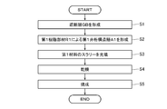
- FIG. 3 is a flowchart showing this manufacturing method.
- the blocking layer GB is formed by the first member M1 extending in a flat plate shape (S1).
- the first member M1 can be formed in a semi-cured state by applying a slurry composed of the first material and a binder on a flat surface by using a coating device (not shown) and then drying the slurry.
- the double girder structure layer of the first resin member R1 is formed on one surface of the first member M1 by a 3D printer (S2). That is, in the first layer L1, the first resin member R1 extends in the first direction (X direction) and is arranged at a predetermined interval in the second direction (Y direction) intersecting the first direction, In the second layer L2, the second layer L2 extends in a third direction (Y direction) intersecting the first direction and is arranged at a predetermined interval in a fourth direction (X direction) intersecting the third direction. By repeating this process a predetermined number of times, the double girder structure layer of the first resin member R1 is formed.
- this double girder structure layer is referred to as a first double girder structure layer A1 (not shown).
- thermoplastic resin such as polyethylene, polystyrene, ABS resin, polypropylene resin, nylon resin, or polycarbonate can be used.
- the slurry of the first material is filled in the gaps of the first double girder structure layer A1 (S3).
- filling methods There are various conceivable filling methods. For example, a method of immersing the first double girder structure layer A1 in a slurry container storing a slurry of the first material may be used.
- the first cross beam structure layer A1 filled with the first material is dried to semi-cure the second member M2 (S4).
- the composite of the first resin member R1 and the first material generated by this is hereinafter referred to as a second double girder structure layer A2 (not shown).
- first member M1 and the second double girder structure layer A2 are fired in a firing furnace (S5).
- the first resin member R1 is decomposed and disappears, and the electrolyte 21 of the present embodiment can be obtained.
- the layer thickness and shape of the blocking layer GB in the electrolyte 2 the number of layers of the double girder structure layer CS, the shapes and sizes of the first member M1 and the second member M2, and the like are shown as examples, and the illustrated structure is shown. It is not limited to.
- the electrolyte 21 constitutes the double-girder structure, so that the three-phase interface between the electrode 3a or 3b and the gas can be significantly improved, and the power density of the battery is improved. To do. Further, since the electrolyte 21 can be manufactured using a 3D printer, it is possible to improve the material efficiency of the raw material as compared with the conventional coating or the like.
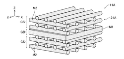
- the electrolyte 21A of the first modification forms a first cross girder structure layer A1 by the first resin member R1 on both sides of the first member M1 using a 3D printer, and then forms a first material in the gaps of the first cross girder structure layer A1. It can be formed by filling.
- the second member M2 forming the double girder structure layer CS is a material different from the first member M1 used for the blocking layer GB.
- the point is different from the first embodiment.
- the first member M1 is made of the first material and the second member M2 is made of the second material.
- Appropriate materials can be selected for the first material and the second material in consideration of respective characteristics and manufacturing processes.
- the first material M1 and the second material M2 are preferably materials that can be bonded to each other in order to ensure ionic conductivity.
- the double beam structure layer CS may be formed on both surface sides of the blocking layer GB.
- the first material and the second material are appropriately selected and the blocking layer GB and the double beam structures on both sides are formed.
- the layer CS can be formed. It goes without saying that it is also possible to form the blocking layer GB with the second material and form the double girder structure layer CS with the first material. According to this structure, the above-described effects can be achieved, and the range of selection of materials for the blocking layer GB and the double girder structure layer CS that are the electrolyte 21B can be widened.
- the second member M2 since the second member M2 has gas permeability, the gas permeability of the electrolyte 21C as a whole is good. Therefore, in some cases, it is not necessary to form a gap for the gas flow path between the electrolyte 21C and the electrode 3a or 3b, and the space efficiency is good and the manufacturing process is facilitated. ..
- the double girder structure layer CS having the second member M2 of the porous body may be formed on both surface sides of the blocking layer GB. According to this structure, it is possible to obtain the above-described effects and further improve the gas permeability in the double girder structure layer CS.
- the electrolyte 21D of the cell structure 11D of Modification 4 is the above modification in that the second member M2 forming the double girder structure layer CS is formed of a porous body having gas permeability.
- the first member M1 and the second member M2 are made of different materials.
- the first member M1 is made of the first material
- the second member M2 is made of the second material.
- Appropriate materials can be selected for the first material and the second material in consideration of respective characteristics and manufacturing processes.
- the first material M1 and the second material M2 are preferably materials that can be bonded to each other in order to ensure ionic conductivity.
- the double girder structure layer CS having the porous second member M2 may be formed on both surface sides of the blocking layer GB.
- the first material and the second material are appropriately selected.
- the blocking layer GB and the double-sided structure layers CS on both sides can be formed.
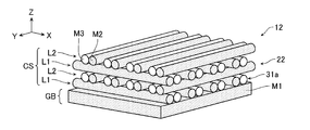
- FIG. 8 is a perspective view showing the cell structure 12 according to the second embodiment.
- the cell structure 12 according to this embodiment has an electrolyte 22 and an electrode 31a.
- the electrolyte 22 includes a first member M1 that constitutes the barrier layer GB, and a second member M2 that constitutes a part of the double girder structure layer CS joined to one surface side of the barrier layer GB.
- the double girder structure layer CS is composed of a composite of a second member M2 forming the electrolyte 22 and a third member M3 forming the electrode 31a.
- the blocking layer GB is configured by the first member M1 formed in a plate shape as in the first embodiment, but the double girder structure layer CS is the second member in the first embodiment.
- the third embodiment is different from the first embodiment in that it includes a member M2 and a third member M3 that is arranged adjacent to the second member M2 and that is made of an electron transport material that serves as the electrode 31a.
- the double girder structure layer CS has a repeating structure of a first layer L1 and a second layer L2.
- the second member M2 and the third member M3 continuously extend with the first direction (X direction) as the longitudinal direction, and in the second direction (Y direction) intersecting the first direction, One side is adjacent to the other side, and the other side is arranged with a predetermined gap (for example, a gap corresponding to one of the second member M2 or the third member M3).
- the second member M2 and the third member M3 continuously extend with the third direction (Y direction) intersecting the first direction as the longitudinal direction and intersect the third direction.
- the fourth direction (X direction) they are adjacent to each other on one side and arranged with a predetermined gap on the other side.
- the gap between the first layer L1 and the second layer L2 forms a gas flow path.
- the second member M2 of the first layer L1 and the second member M2 of the second layer L2 are joined to each other in the fifth direction (Z direction).
- the third member M3 of the first layer L1 and the third member M3 of the second layer L2 are also joined to each other in the fifth direction (Z direction). Further, the second member M2 contacting the blocking layer GB is joined to the blocking layer GB in the fifth direction.
- FIG. 8 is only the configuration of one side of the electrolyte 22 and the electrode 31a of the cell structure 12.
- the structure on the other side of the electrolyte 21 and the structure of the electrode 31b (not shown) are arbitrary.
- the electrode 31a air electrode: cathode
- the electrode 31b fuel electrode: anode
- Conductive ceramics such as (La,Sr)MnO 3 , La,Sr(Co,Fe)O 3 , and (La,Sr)NiO 4 can be used as the third material.
- Ni-YSZ cermet or the like can be used as the fourth material.
- the second member M2 forming the electrolyte 22 a thread-shaped member extending in a predetermined direction is used, so that the second member M2 can be manufactured using a 3D printer. If the 3D printer can handle the slurry containing the first material and the third material, after forming the first member M1 with the 3D printer, the second member M2 and the third member M3 are shaped in a cross pattern. Then, by finally firing, the electrolyte 22 of FIG. 8 can be formed.
- the 3D printer cannot handle the slurries or powders of the first material to the third material, as in the first embodiment, for example, a 3D printer of FDM (Fusion Melt Laminating Method) is used.
- FDM Fusion Melt Laminating Method
- the cell structure 12 can also be manufactured by forming the double-girder structure layer with a thermoplastic resin. Hereinafter, this manufacturing method will be described.
- FIG. 9 is a flowchart showing this manufacturing method.
- the blocking layer GB is formed by the first member M1 extending in a flat plate shape (S11).
- the first member M1 can be formed in a semi-cured state by applying a slurry composed of the first material and a binder on a flat surface by using a coating device (not shown) and then drying the slurry.
- a 3D girder structure layer A3 of the first resin member R1 and the second resin member R2 is formed on one surface of the first member M1 by a 3D printer (S12). That is, in the first layer L1, one of the first resin member R1 and the second resin member R2 extends in the first direction (X direction), and one of the first resin member R1 and the second resin member R2 extends in the second direction (Y direction) intersecting the first direction.
- the side surfaces are in close contact with each other, and the other side surface is arranged at a predetermined interval, and in the second layer L2, a fourth direction intersects the third direction (Y direction) and crosses the third direction.
- the third cross beam structure layer A3 of the first resin member R1 and the second resin member R2 is formed.
- the first resin member R1 and the second resin member R2 are decomposed by different first decomposition process and second decomposition process, respectively.
- first resin member R1 polyethylene resin (PE)
- water-soluble PVA can be used as the second resin member R2.
- the slurry containing the first material is filled in the gaps of the third double girder structure layer A3 (S13).
- various filling methods can be considered, for example, a method of immersing the third double girder structure layer A3 in a slurry container in which a slurry of the first material is stored may be used.
- the third cross girder structure layer A3 filled with the first material is dried to anti-cure the second member M2 (S14).
- the fourth double girder structure layer A4 as shown in FIG. 10B is formed.
- the fourth girder structure layer A4 is immersed in hot water of a predetermined temperature for a predetermined time to decompose and remove the second resin material R2 (S15).
- a fifth double girder structure layer A5 in which the second resin material R2 is removed from the fourth double girder structure layer A4 is obtained.
- the sixth double girder structure layer A6 is obtained (S16).
- the first member M1 and the sixth double girder structure A6 are fired in a firing furnace (S17).
- the first resin material R1 decomposes and disappears, and the cell structure 12 of the present embodiment is obtained.
- the number, the thickness, and the shape of the blocking layer GB in the cell structure 12, or the shapes, sizes, and arrangements of the second member and the third member in the number of the stacked double-layer structure layers CS are shown as examples. Therefore, the structure is not limited to the illustrated structure.
- the cell structure 12 having such a structure can be used as a cell of a solid oxide fuel cell, for example.
- the gas beam structure layer CS of the cell structure 12 allows, for example, gas to pass in any of the X, Y, and Z directions, and at the same time, the electrolyte 22 (first member M1 and second member M2) in contact with the gas.
- the three-phase interface of the electrode 31a (third member M3) which is the electron transport material, can be widened per unit volume.
- the material efficiency of the raw material can be improved as compared with a manufacturing method such as coating.
- the blocking layer GB that constitutes the electrolyte 22 is formed by the flat plate-shaped first member M1, but in the cell structure 12A of the modified example 1, as shown in FIG.
- the blocking layer GB forming the electrolyte 22A is formed by arranging the thread-shaped first member M1 supplied by a 3D printer or the like without any gap.
- the blocking layer GB is formed by aligning the thread-shaped first material members M1 in parallel and closely adhering to each other, and rotating the longitudinal direction of the first member M1 up and down by 90 degrees so as to be stacked vertically to form a plate shape. It is the one.
- the blocking layer GB is formed by heating the slurry containing the first material to a predetermined temperature by, for example, a 3D printer or the like so as to prevent electrolyte contraction, and extending the first layer with the X direction as the longitudinal direction and without gaps in the Y direction.
- the second layer is formed by forming it into a raft shape having a dense structure capable of blocking gas by arranging the second layer in the X direction with no gaps while extending in the Y direction as the longitudinal direction.
- FIG. 12A is a perspective view showing a cell structure 12B of Modification 2
- FIG. 12B is a perspective view of only the electrodes 31a and 31b
- FIG. 12C is a perspective view of only the electrolyte 22B. It is a perspective view.
- the double girder structure layer CS is bonded to one surface side of the blocking layer GB, but as shown in FIG.
- the body 12B is different from the modified example 1 of the second embodiment in that the double girder structure layers CS are joined to both surface sides of the blocking layer GB.
- Air containing oxygen (O 2 ) is introduced into the gas passage on one side (upper side) of the barrier layer GB, and hydrogen (H 2 ) is contained in the gas passage on the other side (lower side).
- Fuel gas is introduced.
- Water (H 2 O) generated after the reaction is discharged to the outside from the gas passage on the lower side.
- the electrodes 31a and 31b forming the double-sided structure layer CS are connected to the solid oxide fuel cell. It becomes possible to make it act as an air electrode and a fuel electrode, respectively.
- FIG. 12B when the electrodes 31a and 31b of the double beam structure layer CS are viewed from the viewpoint of the electron transport material, all the third members M3 forming the electrodes 31a and 31b are all formed. Because of the connected structure, the electrodes 31a and 31b have no isolated points, and electrons can be transported with good impedance.
- the electrolyte 22B of the double girder structure layer CS when the electrolyte 22B of the double girder structure layer CS is viewed from the viewpoint of an ionic conductor, all of the first member M1 and the second member M2 forming the electrolyte 22B are connected. Because of the structure, it is possible to transport oxide ions without any particular resistance. If the cell structure 12B configured as described above is used as a solid oxide fuel cell, not only the material efficiency of the raw material can be improved but also the three-phase interface of the reaction field can be expanded, so that the power density can be increased. It becomes possible to improve.
- the cell structure 12C according to Modification 3 is different from the cell structure according to Modification 1 in the second embodiment in that the double-sided structure layer CS is bonded to one surface side of the blocking layer GB. Same as 12A.
- the second point is that the third member M3 forming the electrode 32Ca of the double-sided structure portion CS is formed of an electron transporting material made of a gas-permeable porous body. This is different from the cell structure 12A of the modified example 1 of the embodiment.
- the double girder structure layer CS similar to that in FIG. 13 may be formed on both sides of the blocking layer GB, for example.
- the second member M2 forming the double girder structure layer CS may be formed of a porous body. According to this structure, it is possible to obtain the above-described effects and further improve the gas permeability in the double girder structure layer CS.
- Modification Example 4 of the cell structure 12 according to the second embodiment will be described.
- the cell structure 12D of the modified example 4 is similar to the cell structure 12B of the modified example 2 in that the double-sided structure layers CS are respectively bonded to both surface sides of the blocking layer GB.
- the layout of the second member M2 and the third member M3 forming the double girder structure layer CS is different from that of the cell structure 12B of Modification 2.
- the second member M2 and the third member M3 of the double girder structure layer CS are arranged in a so-called vertically stacked layout in the fifth direction (Z direction).
- this modification 4 as shown in FIG. 14B, since the third members M3 forming the electrodes 32Da and 32Db are all connected in the fifth direction, electrons are transported with a good impedance without an isolated point. it can.
- FIG. 14C since the second member M2 forming the electrolyte 22D is all connected in the fifth direction, the oxide ions can be transported without any particular resistance.
- the cell structure 12D including the double-girder structure layer CS having the layout structure of Modification 4 can also achieve the above-described effects.
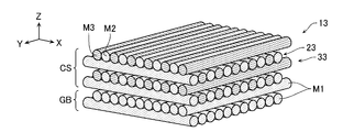
- the cell structure 13 according to the third embodiment will be described.
- the second member M2 and the third member M3 of the double girder structure layer CS on the barrier layer GB are arranged adjacent to each other without a gap in each layer.
- the difference is that the cell structure 12 of the second embodiment is different.
- the third member M3 is a porous body and can form a gas flow path inside.
- the second member M2 is made porous, or both the second member M2 and the third member M3 are made porous, and the second member M2 and the third member are provided on both surface sides of the blocking layer GB.
- a cell structure including the double girder structure layer CS in which M3 are arranged adjacent to each other without a gap may be formed. According to such a configuration, the gas can reach the reaction field through the third member M3 or the second member M2, so that it is possible to further widen the three-phase interface per unit volume.
- the cell structure 13 can also achieve the above-described effects.
- the cell structures 11 to 13 described above can be used as the electrode structure of the secondary battery, or the cell structures 12 or 13 described above can be used as the electrode structure of the fuel cell. ..
- the storage efficiency is improved and a compact design is possible.
- the three-phase interface per unit volume can be widened to improve the output density and improve the material efficiency of the raw material.
- the resin material when used as the frame structure of the negative element for forming the double-girder structure layer CS, it is possible to form the electrolyte and the electrode into the double-girder structure, which was conventionally difficult to form. It is possible to use the cell structure having the double beam structure of these materials in a fuel cell or a secondary battery.
Landscapes
- Life Sciences & Earth Sciences (AREA)
- Engineering & Computer Science (AREA)
- Manufacturing & Machinery (AREA)
- Sustainable Development (AREA)
- Sustainable Energy (AREA)
- Chemical & Material Sciences (AREA)
- Chemical Kinetics & Catalysis (AREA)
- Electrochemistry (AREA)
- General Chemical & Material Sciences (AREA)
- Fuel Cell (AREA)
- Secondary Cells (AREA)
Abstract
セル構造体は、イオン伝導性を有する電解質と、前記電解質の両側に配置され電子伝導性を有する一対の電極と、を有するセル構造体において、前記電解質が、前記一対の電極を分離する第1部材と、前記第1部材の少なくとも一方の側に接合され、井桁構造層の少なくとも一部を構成すると共に、前記第1部材から順に第1の層及び第2の層を形成する複数の第2部材とを備え、前記第2部材が、前記第1の層において、第1方向に延び、前記第1方向と交差する第2方向に配列され、前記第2の層において、前記第1方向と交差する第3方向に延び、前記第3方向と交差する第4方向に配列され、前記第1の層に属する前記第2部材と前記第2の層に属する第2部材とは、互いに接合されている。
Description
本発明は、セル構造体及びその製造方法並びに燃料電池及び二次電池に関する。
天然ガスや水素、又はその他の燃料の酸化によって電気を発生させるシステムとして、固体酸化物形燃料電池(SOFC:Solid Oxide Fuel Cell)が知られている(例えば、特許文献1参照)。この固体酸化物形燃料電池においては、電解質と接合する電極を、例えばエアロゾルデポジション法により塗布形成している。
しかしながら、上記特許文献1に開示された従来の固体酸化物形燃料電池は、電極材料を電解質に塗布形成して製造されるため、使用する原材料のコスト比率が高いままであり、生産量が増えてもコストを低減させることが難しいという問題がある。また、現状の固体酸化物形燃料電池においては、反応場における燃料や酸素と接する電解質と電極の三相界面をより拡げることで、より出力密度が高くなるセル構造体の実現も望まれている。
本発明は、上記事情に鑑みてなされたものであり、反応場の三相界面を拡げ得るセル構造体及びその製造方法並びに燃料電池及び二次電池を提供することを目的とする。
本発明に係るセル構造体は、イオン伝導性を有する電解質と、前記電解質の両側に配置され電子伝導性を有する一対の電極と、を有するセル構造体において、前記電解質が、前記一対の電極を分離する第1部材と、前記第1部材の少なくとも一方の側に接合され、井桁構造層の少なくとも一部を構成すると共に、前記第1部材から順に第1の層及び第2の層を形成する複数の第2部材とを備え、前記第2部材が、前記第1の層において、第1方向に延び、前記第1方向と交差する第2方向に配列され、前記第2の層において、前記第1方向と交差する第3方向に延び、前記第3方向と交差する第4方向に配列され、前記第1の層に属する前記第2部材と前記第2の層に属する第2部材とは、互いに接合されている。
また、本発明に係るセル構造体の製造方法は、イオン伝導性を有する電解質と、前記電解質の両側に配置され電子伝導性を有する一対の電極と、を有するセル構造体の製造方法において、平板状に延びる第1部材を形成し、前記第1部材の少なくとも一方の面上に第1の分解プロセスにより分解する複数の第1樹脂部材を、第1の層においては、第1方向に延び、前記第1方向と交差する第2方向に所定の間隔を空けて配列させ、第2の層においては、前記第1方向と交差する第3方向に延び、前記第3方向と交差する第4方向に間隔をかけて配列させることにより、前記第1樹脂部材の井桁構造層を形成し、前記第1樹脂部材の井桁構造層の隙間に第2部材のスラリーを充填し、前記第1の分解プロセスにより前記第1樹脂部材を分解すると共に、前記第2部材を焼成することにより前記第1部材及び第2部材で前記電解質を形成する。
本発明によれば、固体酸化物形燃料電池等に適用可能なセル構造体によって、原材料の材料効率を改善させて反応場の三相界面を拡げ得る構造を有することができる。
以下、添付の図面を参照して、本発明の実施形態に係るセル構造体を詳細に説明する。ただし、以下の実施形態は、各請求項に係る発明を限定するものではなく、また、実施形態の中で説明されている特徴の組み合わせの全てが発明の解決手段に必須であるとは限らない。
まず、本実施形態を説明する前に、一般的な燃料電池の構造について説明する。
図1は、固体酸化物形燃料電池(SOFC)の概略的な構成を示す図である。
図示のように、燃料電池10は、内部にセル構造体1を有する。セル構造体1は、イオン伝導性を有する電解質2と、この電解質2の両側に配置された電子伝導性を有する一対の電極3a,3bとを有する。電解質2はガスを遮断可能な遮断層を形成し、一方に酸素O2を含む空気、他方に燃料(例えば水素H2など)が通る流路4a,4bを形成している。
図1は、固体酸化物形燃料電池(SOFC)の概略的な構成を示す図である。
図示のように、燃料電池10は、内部にセル構造体1を有する。セル構造体1は、イオン伝導性を有する電解質2と、この電解質2の両側に配置された電子伝導性を有する一対の電極3a,3bとを有する。電解質2はガスを遮断可能な遮断層を形成し、一方に酸素O2を含む空気、他方に燃料(例えば水素H2など)が通る流路4a,4bを形成している。
このように構成された燃料電池10では、流路4aに導入された空気中の酸素O2が、電解質2と電極3aとの三相界面で電極3aから電子を受け取ってイオン化される。酸素イオンは、電解質2を通り、電極3b側に移動する。一方、流路4bに導入された水素H2は、電解質2を介して伝送された酸化物イオンと反応して水(H2O)や二酸化炭素(CO2)を生成し、電極3bに電子を渡す。電極3aから電極3bへと流れる電子が、負荷に流れる電流を生成する。出力密度を高めるには、電解質2と電極3a,3bとガスとの三相界面を拡大することが有効である。
[第1の実施形態]
次に、三相界面拡大を図った本実施形態に係るセル構造体11を、図2に基づいて説明する。なお、図2に示したものは、このセル構造体11のうちの電解質21の一方の側の構成のみである。電解質21の他方の側の構造及び電極3a又は3bの構造については任意である。
次に、三相界面拡大を図った本実施形態に係るセル構造体11を、図2に基づいて説明する。なお、図2に示したものは、このセル構造体11のうちの電解質21の一方の側の構成のみである。電解質21の他方の側の構造及び電極3a又は3bの構造については任意である。
セル構造体11を構成する電解質21は、ガスをシールドして遮断可能な平板状に形成された遮断層GBを形成する第1部材M1と、この第1部材M1の片面(図示の例では上面)側に接合された井桁構造層CSを形成する複数の第2部材M2とを備えて構成されている。なお、図2及びそれ以降の図面においては、各構成要素の縮尺や寸法が誇張されて示されている場合や、一部の構成要素が省略されている場合がある。
井桁構造層CSは、遮断層GB側から順に第1の層L1及び第2の層L2が繰り返される繰返し構造を有する。第2部材M2は、第1の層L1では、第1方向(例えば、図中X方向)を長手方向として連続的に延びると共に、第1方向と交差する第2方向(例えば、図中Y方向)に所定の隙間を空けて配列されている。
一方、第2部材M2は、第2の層L2では、第1方向と交差する第3方向(例えば、図中Y方向)を長手方向として連続的に延びると共に、第3方向と交差する第4方向(例えば、図中X方向)に所定の隙間を空けて配列されている。より具体的には、第1の層L1及び第2の層L2における第2部材M2は、その交差部において直交するように、それぞれの層で平行に配置されている。なお、第1の層L1及び第2の層L2における第2部材M2は、その交差部において直交しないように配列するようにしても良い。
これら第1の層L1の第2部材M2と第2の層L2の第2部材M2とは、第1方向、第2方向、第3方向及び第4方向と交差する第5方向(例えば、図中Z方向)で互いに接合されている。また、第1の層L1の第2部材M2は、第5方向で第1部材M1と接合されている。これにより、井桁構造層CSと遮断層GBとは、第5方向で接合され、固体電解質21は一体として構成される。
本実施形態では、第1部材M1と第2部材M2とが同一の第1材料にて形成されている。第1材料としては、気密性を有する緻密構造を有し、イオン伝導性を有するものを用いることができる。例えば、第1材料として、無機物等の誘電体で、酸化アルミニウム、ジルコニア、炭化ケイ素、窒化ケイ素などのセラミックの粒子や、二酸化ケイ素、酸化ホウ素、五酸化二リン、炭酸ナトリウム、炭酸カルシウム、酸化チタン等のガラスの原料となる物質を用いることができる。また、イットリア安定化ジルコニア(YSZ)やセリア系酸化物やそれらの複合酸化物などの酸化物イオン導電性セラミックスも第1材料として用いることができる。
なお、この電解質21に対向する電極3a又は3bの構造は、図示していないが、第2部材M2の隙間に挿入され、且つガスの流路となる隙間が確保される構造であれば、どのような構造でも良い。また、電極3a,3bがポーラス体であれば、電極3a,3b自体にガスの流路が形成されるので、電極3a,3bを全ての隙間に充填されるように形成することもできる。
[セル構造体11の製造方法]
次に、上記のセル構造体11の製造方法について説明する。
電解質21を構成する第2部材M2として、所定方向に延びる糸状の部材を使用しているので、3Dプリンタを利用して製造することができる。3Dプリンタが第1材料を含むスラリーを取り扱うことができるものであれば、3Dプリンタで第1部材M1を形成したのちに、第2部材M2を井桁状に造形して、最後に焼成することにより、図2の電解質21を形成することができる。
次に、上記のセル構造体11の製造方法について説明する。
電解質21を構成する第2部材M2として、所定方向に延びる糸状の部材を使用しているので、3Dプリンタを利用して製造することができる。3Dプリンタが第1材料を含むスラリーを取り扱うことができるものであれば、3Dプリンタで第1部材M1を形成したのちに、第2部材M2を井桁状に造形して、最後に焼成することにより、図2の電解質21を形成することができる。
一方、3Dプリンタが第1材料のスラリーを取り扱うことができない場合には、例えばFDM(熱溶解積層方式)の3Dプリンタを利用して熱可塑性樹脂で井桁構造層を造形することにより、セル構造体11を製造することもできる。以下、この製造方法について説明する。
図3は、この製造方法を示すフローチャートである。
まず、平板状に延びる第1部材M1による遮断層GBを形成する(S1)。第1部材M1は、第1材料とバインダからなるスラリーを図示しない塗布装置を使用して平面上に塗布したのち、乾燥させることにより、半硬化状態で形成することができる。
まず、平板状に延びる第1部材M1による遮断層GBを形成する(S1)。第1部材M1は、第1材料とバインダからなるスラリーを図示しない塗布装置を使用して平面上に塗布したのち、乾燥させることにより、半硬化状態で形成することができる。
次に、第1部材M1の一方の面上に、3Dプリンタによって、第1樹脂部材R1の井桁構造層を造形する(S2)。すなわち、第1樹脂部材R1を、第1の層L1においては、第1方向(X方向)に延び、第1方向と交差する第2方向(Y方向)に所定の間隔を空けて配列させ、第2の層L2においては、第1方向と交差する第3方向(Y方向)に延び、第3方向と交差する第4方向(X方向)に所定の間隔を空けて配列させる。この工程を所定回数繰り返すことにより、第1樹脂部材R1の井桁構造層を形成する。以下、この井桁構造層を第1井桁構造層A1(図示せず)と称する。
第1樹脂部材R1としては、例えば、ポリエチレン、ポリスチレン、ABS樹脂、ポリプロピレン樹脂、ナイロン樹脂、ポリカーボネートなどの熱可塑性樹脂を用いることができる。
次に、第1井桁構造層A1の隙間に第1材料のスラリーを充填する(S3)。充填方法としては、種々考えられるが、例えば第1材料のスラリーを貯留したスラリー容器内に第1井桁構造層A1を浸漬させる方法によっても良い。
次に、第1材料が充填された第1井桁構造層A1を乾燥させて第2部材M2を半硬化させる(S4)。これにより生成される第1樹脂部材R1と第1材料との複合体を、以下、第2井桁構造層A2(図示せず)と称する。
最後に、第1部材M1と第2井桁構造層A2を焼成炉で焼成する(S5)。これにより、第1樹脂部材R1が分解消失して本実施形態の電解質21を得ることができる。
なお、電解質2における遮断層GBの層厚や形状、或いは井桁構造層CSの積層数や第1部材M1及び第2部材M2の形状、大きさ等は例として図示したものであり、図示の構造に限定されるものではない。
本実施形態に係るセル構造体11によれば、電解質21が井桁構造体を構成するので、電極3a又は3b及びガスとの三相界面を格段に向上させることができ、電池の出力密度が向上する。また、上記の電解質21は、3Dプリンタを用いて製造することが可能であるので、従来の塗布等と比較して、原材料の材料効率を改善させることが可能となる。
[第1の実施形態の変形例1]
次に、第1の実施形態に係るセル構造体11の変形例1について説明する。
第1の実施形態のセル構造体11の電解質21では、遮断層GBの片面側に井桁構造層CSが接合されていたが、図4に示すように、変形例1のセル構造体11Aの電解質21Aは、遮断層GBの両面側にそれぞれ井桁構造層CSが接合されている点が、第1の実施形態とは相違している。
次に、第1の実施形態に係るセル構造体11の変形例1について説明する。
第1の実施形態のセル構造体11の電解質21では、遮断層GBの片面側に井桁構造層CSが接合されていたが、図4に示すように、変形例1のセル構造体11Aの電解質21Aは、遮断層GBの両面側にそれぞれ井桁構造層CSが接合されている点が、第1の実施形態とは相違している。
この変形例1の電解質21Aは、第1部材M1の両側に3Dプリンタにより第1樹脂部材R1による第1井桁構造層A1を造形し、その後、第1井桁構造層A1の隙間に第1材料を充填することで形成することができる。
このように、遮断層GBの両面側に井桁構造層CSが形成された変形例1のセル構造体1Aによれば、出力密度を更に向上させることが可能となる。
[第1の実施形態の変形例2]
次に、第1の実施形態に係るセル構造体11の変形例2について説明する。
図5に示すように、変形例2のセル構造体11Bの電解質21Bは、井桁構造層CSを構成する第2部材M2が、遮断層GBに用いられた第1部材M1とは異なる材料である点が、第1の実施形態と相違している。変形例2では、第1部材M1が第1材料、第2部材M2が第2材料で形成されている。第1材料及び第2材料は、それぞれの特性や製造工程を考慮して、適切な材料を選択することができる。第1材料M1と第2材料M2とは、イオン伝導性を確保するために、互いに結合可能な材料であることが望ましい。
次に、第1の実施形態に係るセル構造体11の変形例2について説明する。
図5に示すように、変形例2のセル構造体11Bの電解質21Bは、井桁構造層CSを構成する第2部材M2が、遮断層GBに用いられた第1部材M1とは異なる材料である点が、第1の実施形態と相違している。変形例2では、第1部材M1が第1材料、第2部材M2が第2材料で形成されている。第1材料及び第2材料は、それぞれの特性や製造工程を考慮して、適切な材料を選択することができる。第1材料M1と第2材料M2とは、イオン伝導性を確保するために、互いに結合可能な材料であることが望ましい。
なお、図示は省略するが、例えば遮断層GBの両面側に井桁構造層CSを形成しても良く、この場合は第1材料及び第2材料を適宜選択して遮断層GB及び両側の井桁構造層CSを形成することができる。また、遮断層GBを第2材料により形成し、井桁構造層CSを第1材料により形成することも可能であることは言うまでもない。このように構成すれば、上記の作用効果を奏することができると共に、電解質21Bである遮断層GB及び井桁構造層CSの材料選択の幅を広げることができる。
[第1の実施形態の変形例3]
次に、第1の実施形態に係るセル構造体11の変形例3について説明する。
図6に示すように、変形例3のセル構造体11Cの電解質21Cは、遮断層GBを構成する第1部材M1がガス遮断性を有する緻密構造であるのに対し、井桁構造層CSを構成する第2部材M2がガス透過性を有するポーラス体により構成されている点が、第1の実施形態のセル構造体11とは相違している。また、この変形例3では、第1部材M1と第2部材M2とが、同一の第1材料にて形成されている。
次に、第1の実施形態に係るセル構造体11の変形例3について説明する。
図6に示すように、変形例3のセル構造体11Cの電解質21Cは、遮断層GBを構成する第1部材M1がガス遮断性を有する緻密構造であるのに対し、井桁構造層CSを構成する第2部材M2がガス透過性を有するポーラス体により構成されている点が、第1の実施形態のセル構造体11とは相違している。また、この変形例3では、第1部材M1と第2部材M2とが、同一の第1材料にて形成されている。
この変形例3によれば、第2部材M2がガス透過性を有しているので、電解質21C全体としてのガス透過性が良好である。このため、場合によっては、電解質21Cと電極3a又は3bとの間にガスの流路のための隙間を形成しなくても良く、その分空間効率が良好であり、且つ製造工程も容易になる。
なお、図示は省略するが、例えば遮断層GBの両面側にポーラス体の第2部材M2を有する井桁構造層CSを形成しても良いことは言うまでもない。このように構成すれば、上記の作用効果を奏することができると共に、井桁構造層CSにおけるガス透過性を更に向上させることが可能となる。
[第1の実施形態の変形例4]
次に、第1の実施形態に係るセル構造体1の変形例4について説明する。
図7に示すように、変形例4のセル構造体11Dの電解質21Dは、井桁構造層CSを構成する第2部材M2が、ガス透過性を有するポーラス体により構成されている点で、上記変形例3と同様であるが、第1部材M1と第2部材M2とが異なる材料にて形成されている点が上記変形例3と異なる。変形例4では、例えば第1部材M1が第1材料、第2部材M2が第2材料で形成されている。第1材料及び第2材料は、それぞれの特性や製造工程を考慮して、適切な材料を選択することができる。第1材料M1と第2材料M2とは、イオン伝導性を確保するために、互いに結合可能な材料であることが望ましい。
次に、第1の実施形態に係るセル構造体1の変形例4について説明する。
図7に示すように、変形例4のセル構造体11Dの電解質21Dは、井桁構造層CSを構成する第2部材M2が、ガス透過性を有するポーラス体により構成されている点で、上記変形例3と同様であるが、第1部材M1と第2部材M2とが異なる材料にて形成されている点が上記変形例3と異なる。変形例4では、例えば第1部材M1が第1材料、第2部材M2が第2材料で形成されている。第1材料及び第2材料は、それぞれの特性や製造工程を考慮して、適切な材料を選択することができる。第1材料M1と第2材料M2とは、イオン伝導性を確保するために、互いに結合可能な材料であることが望ましい。
なお、図示は省略するが、例えば遮断層GBの両面側にポーラス体の第2部材M2を有する井桁構造層CSを形成しても良く、この場合は第1材料及び第2材料を適宜選択して遮断層GB及び両側の井桁構造層CSを形成することができる。また、遮断層GBを第2材料により形成し、井桁構造層CSを第1材料により形成することも可能である。このように構成すれば、上記の作用効果を奏することができると共に、電解質21Dである遮断層GB及び井桁構造層CSの材料選択の幅を広げながら、井桁構造層CSにおけるガス透過性を更に向上させることができる。
[第2の実施形態]
次に、第2の実施形態に係るセル構造体12について説明する。なお、第2の実施形態以降の説明においては、第1の実施形態及びその変形例と同一の構成要素に関しては同一の符号を付しているので、以下では重複する説明は省略する。
次に、第2の実施形態に係るセル構造体12について説明する。なお、第2の実施形態以降の説明においては、第1の実施形態及びその変形例と同一の構成要素に関しては同一の符号を付しているので、以下では重複する説明は省略する。
図8は、第2の実施形態に係るセル構造体12を示す斜視図である。図8に示すように、本実施形態に係るセル構造体12は、電解質22と電極31aとを有する。電解質22は、遮断層GBを構成する第1部材M1と、この遮断層GBの片面側に接合された井桁構造層CSの一部を構成する第2部材M2とを備えている。井桁構造層CSは、電解質22を構成する第2部材M2と、電極31aを構成する第3部材M3との複合体により構成されている。
本実施形態においては、遮断層GBは、第1の実施形態と同様、板状に形成された第1部材M1により構成されているが、井桁構造層CSが、第1の実施形態における第2部材M2と、この第2部材M2に隣接して配置された、電極31aとなる電子輸送材料からなる第3部材M3とを備えている点で、第1の実施形態と相違している。
具体的には、図8に示すように、井桁構造層CSは、第1の層L1及び第2の層L2の繰返し構造を有する。第1の層L1では、第2部材M2及び第3部材M3は、第1方向(X方向)を長手方向として連続的に延びると共に、第1方向と交差する第2方向(Y方向)において、一方の側では隣接し、他方の側では所定の隙間(例えば、第2部材M2又は第3部材M3の1本分の隙間)を空けて配列されている。
一方、第2の層L2では、第2部材M2及び第3部材M3は、第1方向とは交差する第3方向(Y方向)を長手方向として連続的に延びると共に、第3方向と交差する第4方向(X方向)において、一方の側では隣接し、他方の側では所定の隙間を空けて配列されている。第1の層L1及び第2の層L2の隙間は、ガスの流路を形成する。
これら第1の層L1の第2部材M2と第2の層L2の第2部材M2とは、第5方向(Z方向)で互いに接合されている。また、第1の層L1の第3部材M3と第2の層L2の第3部材M3も、第5方向(Z方向)で互いに接合されている。更に、遮断層GBに接する第2部材M2は、第5方向で遮断層GBと接合されている。
なお、図8に示したものは、このセル構造体12のうちの電解質22の一方の側及び電極31aの構成のみである。電解質21の他方の側の構造及び電極31b(不図示)の構造については任意である。
電極31a(空気極:カソード)は第3材料にて形成され、電極31b(燃料極:アノード)は第4材料にて形成される。第3材料としては、(La,Sr)MnO3, La,Sr(Co,Fe)O3, (La,Sr)NiO4等の導電性セラミックスを用いることができる。第4材料としては、Ni-YSZサーメット等を用いることができる。
[セル構造体12の製造方法]
次に、第2の実施形態に係るセル構造体12を製造する方法について説明する。
電解質22を構成する第2部材M2として、所定方向に延びる糸状の部材を使用しているので、3Dプリンタを利用して製造することができる。3Dプリンタが第1材料及び第3材料を含むスラリーを取り扱うことができるものであれば、3Dプリンタで第1部材M1を形成したのちに、第2部材M2及び第3部材M3を井桁状に造形して、最後に焼成することにより、図8の電解質22を形成することができる。
次に、第2の実施形態に係るセル構造体12を製造する方法について説明する。
電解質22を構成する第2部材M2として、所定方向に延びる糸状の部材を使用しているので、3Dプリンタを利用して製造することができる。3Dプリンタが第1材料及び第3材料を含むスラリーを取り扱うことができるものであれば、3Dプリンタで第1部材M1を形成したのちに、第2部材M2及び第3部材M3を井桁状に造形して、最後に焼成することにより、図8の電解質22を形成することができる。
一方、3Dプリンタが第1材料~第3材料のスラリー又は粉体を取り扱うことができない場合には、第1の実施形態と同様に、例えばFDM(熱溶解積層方式)の3Dプリンタを利用して熱可塑性樹脂で井桁構造層を造形することにより、セル構造体12を製造することもできる。以下、この製造方法について説明する。
図9は、この製造方法を示すフローチャートである。
まず、平板状に延びる第1部材M1による遮断層GBを形成する(S11)。第1部材M1は、第1材料とバインダからなるスラリーを図示しない塗布装置を使用して平面上に塗布したのち、乾燥させることにより、半硬化状態で形成することができる。
まず、平板状に延びる第1部材M1による遮断層GBを形成する(S11)。第1部材M1は、第1材料とバインダからなるスラリーを図示しない塗布装置を使用して平面上に塗布したのち、乾燥させることにより、半硬化状態で形成することができる。
次に、図10に示すように、第1部材M1の一方の面上に、3Dプリンタによって第1樹脂部材R1と第2樹脂部材R2の第3井桁構造層A3を造形する(S12)。すなわち、第1樹脂部材R1と第2樹脂部材R2とを、第1の層L1においては、第1方向(X方向)に延び、第1方向と交差する第2方向(Y方向)に一方の側面は密着させ、他方の側面は所定の間隔を空けて配列させ、第2の層L2においては、第1方向と交差する第3方向(Y方向)に延び、第3方向と交差する第4方向(X方向)に一方の側面は密着させ、他方の側面は間隔をかけて配列させる。この工程を所定回数繰り返すことにより、第1樹脂部材R1及び第2樹脂部材R2の第3井桁構造層A3を形成する。
第1樹脂部材R1と第2樹脂部材R2とは、それぞれ異なる第1の分解プロセスと第2の分解プロセスにより分解するものである。具体的には、第1樹脂部材R1として、例えばポリエチレン樹脂(PE)、第2樹脂部材R2として例えば水溶性PVAを用いることができる。
続いて、第3井桁構造層A3の隙間に第1材料を含むスラリーを充填する(S13)。充填方法としては、種々考えられるが、例えば第1材料のスラリーを貯留したスラリー容器内に第3井桁構造層A3を浸漬させる方法によっても良い。
次に、第1材料が充填された第3井桁構造層A3を乾燥させて第2部材M2を反硬化させる(S14)。これにより、図10(b)に示すような第4井桁構造層A4が形成される。
次に、第4井桁構造層A4を、所定の温度の湯に所定時間浸漬して第2樹脂材料R2を分解除去する(S15)。これにより、図10(c)に示すように、第4井桁構造層A4から第2樹脂材料R2が除去された第5井桁構造層A5を得る。
続いて、第5井桁構造層A5の隙間に、第3材料の粉体又はスラリーを充填して、図10(d)に示すように、第5井桁構造層A5と第3材料との複合体である第6井桁構造層A6を得る(S16)。
最後に、第1部材M1と第6井桁構造部A6を焼成炉で焼成する(S17)。これにより、図10(e)に示すように、第1樹脂材料R1が分解消失し、本実施形態のセル構造体12が得られる。
なお、セル構造体12における遮断層GBの積層数、層厚や形状、或いは井桁構造層CSの積層数における第2部材及び第3部材の形状、大きさ、配列態様等は例として図示したものであるので、図示の構造に限定されるものではない。このような構造を有するセル構造体12は、例えば固体酸化物形燃料電池のセルとして利用することが可能である。
すなわち、セル構造体12の井桁構造層CSは、例えばガスがX,Y,Zのいずれの方向にも通過可能であると共に、このガスと接する電解質22(第1部材M1及び第2部材M2)及び電子輸送材料である電極31a(第3部材M3)の三相界面を、単位体積当たり広くすることが可能となる。これにより、固体酸化物形燃料電池の電極として用いた場合、反応場の三相界面を拡げることが可能となる。また、3Dプリンタを用いて製造することができるので、塗布等の製造方法によるものと比較して、原材料の材料効率を改善させることができる。
[第2の実施形態の変形例1]
次に、第2の実施形態に係るセル構造体12の変形例1について説明する。
第2の実施形態のセル構造体12では、電解質22を構成する遮断層GBを平板状の第1部材M1によって形成していたが、変形例1のセル構造体12Aでは、図11に示すように、電解質22Aを構成する遮断層GBが3Dプリンタ等で供給される糸状の第1部材M1を隙間無く配置することによって形成されている。
次に、第2の実施形態に係るセル構造体12の変形例1について説明する。
第2の実施形態のセル構造体12では、電解質22を構成する遮断層GBを平板状の第1部材M1によって形成していたが、変形例1のセル構造体12Aでは、図11に示すように、電解質22Aを構成する遮断層GBが3Dプリンタ等で供給される糸状の第1部材M1を隙間無く配置することによって形成されている。
より具体的には、遮断層GBは、糸状の第1材料部材M1を平行に整列させて密着配置すると共に、第1部材M1の長手方向を上下で90度回転させて上下に重ねて板状にしたものである。この遮断層GBは、第1材料を含んだスラリーを、例えば3Dプリンタ等によって、電解質収縮を防ぐように所定温度に加熱しながら1層目はX方向を長手方向として延ばしつつY方向に隙間なく配列し、2層目はY方向を長手方向として延ばしつつX方向に隙間なく配列することにより、ガスを遮断可能な気密性を有する緻密構造の筏形状に成形することにより造形される。
この変形例1によれば、全ての工程を3Dプリンタで行えるので、より製造コストを抑えることができる。
[第2の実施形態の変形例2]
次に、第2の実施形態に係るセル構造体12の変形例2について説明する。
図12(a)は、変形例2のセル構造体12Bを示す斜視図であり、同図(b)はそのうち電極31a,31bのみの斜視図であり、同図(c)は電解質22Bのみの斜視図である。
第2の実施形態の変形例1のセル構造体12Aでは、遮断層GBの片面側に井桁構造層CSが接合されていたが、図12(a)に示すように、変形例2のセル構造体12Bは、遮断層GBの両面側にそれぞれ井桁構造層CSが接合されている点が、第2の実施形態の変形例1と相違している。遮断層GBの一方の側(上部側)のガス流路には酸素(O2)を含む空気が導入され、他方の側(下方側)のガス流路には、水素(H2)を含む燃料ガスが導入される。反応後に生成される水(H2O)は、下方側のガス流路から外部に排出される。
次に、第2の実施形態に係るセル構造体12の変形例2について説明する。
図12(a)は、変形例2のセル構造体12Bを示す斜視図であり、同図(b)はそのうち電極31a,31bのみの斜視図であり、同図(c)は電解質22Bのみの斜視図である。
第2の実施形態の変形例1のセル構造体12Aでは、遮断層GBの片面側に井桁構造層CSが接合されていたが、図12(a)に示すように、変形例2のセル構造体12Bは、遮断層GBの両面側にそれぞれ井桁構造層CSが接合されている点が、第2の実施形態の変形例1と相違している。遮断層GBの一方の側(上部側)のガス流路には酸素(O2)を含む空気が導入され、他方の側(下方側)のガス流路には、水素(H2)を含む燃料ガスが導入される。反応後に生成される水(H2O)は、下方側のガス流路から外部に排出される。
このように、遮断層GBの両面側に井桁構造層CSが形成された変形例1のセル構造体12Bによれば、井桁構造層CSを構成する電極31a,31bを、固体酸化物形燃料電池の空気極及び燃料極として、それぞれ作用させることが可能となる。具体的には、図12(b)に示すように、井桁構造層CSの電極31a,31bを、電子輸送材料の観点から見た場合、電極31a,31bをそれぞれ構成する第3部材M3が全て繋がった構造となっているため、電極31a,31bに孤立点はなく、良好なインピーダンスで電子を輸送可能となっている。
また、図12(c)に示すように、井桁構造層CSの電解質22Bを、イオン伝導体の観点から見た場合、電解質22Bを構成する第1部材M1及び第2部材M2は、全て繋がった構造となっているため、酸化物イオンを特段の抵抗なく輸送することが可能になっている。そして、このように構成されたセル構造体12Bを、固体酸化物形燃料電池として用いれば、原材料の材料効率を改善させるのみならず、反応場の三相界面を拡げることができるので、出力密度を向上させることが可能となる。
[第2の実施形態の変形例3]
次に、第2の実施形態に係るセル構造体12の変形例3について説明する。
図13に示すように、変形例3のセル構造体12Cは、遮断層GBの片面側に井桁構造層CSが接合されている点では、第2の実施形態の変形例1に係るセル構造体12Aと同様である。しかし、変形例3のセル構造体12Cは、井桁構造部CSの電極32Caを構成する第3部材M3が、ガス透過性を有するポーラス体からなる電子輸送材料により構成されている点が、第2の実施形態の変形例1のセル構造体12Aとは相違している。
次に、第2の実施形態に係るセル構造体12の変形例3について説明する。
図13に示すように、変形例3のセル構造体12Cは、遮断層GBの片面側に井桁構造層CSが接合されている点では、第2の実施形態の変形例1に係るセル構造体12Aと同様である。しかし、変形例3のセル構造体12Cは、井桁構造部CSの電極32Caを構成する第3部材M3が、ガス透過性を有するポーラス体からなる電子輸送材料により構成されている点が、第2の実施形態の変形例1のセル構造体12Aとは相違している。
なお、図示は省略するが、例えば遮断層GBの両面側に、図13と同様の井桁構造層CSを形成しても良いことは言うまでもない。また、井桁構造層CSを構成する第2部材M2をポーラス体により構成するようにすることもできる。このように構成すれば、上記の作用効果を奏することができると共に、井桁構造層CSにおけるガス透過性を更に向上させることが可能となる。
[第2の実施形態の変形例4]
次に、第2の実施形態に係るセル構造体12の変形例4について説明する。
図14(a)に示すように、変形例4のセル構造体12Dは、遮断層GBの両面側にそれぞれ井桁構造層CSが接合されている点が、変形例2のセル構造体12Bと同様であるが、井桁構造層CSを構成する第2部材M2及び第3部材M3のレイアウトが変形例2のセル構造体12Bとは相違している。
次に、第2の実施形態に係るセル構造体12の変形例4について説明する。
図14(a)に示すように、変形例4のセル構造体12Dは、遮断層GBの両面側にそれぞれ井桁構造層CSが接合されている点が、変形例2のセル構造体12Bと同様であるが、井桁構造層CSを構成する第2部材M2及び第3部材M3のレイアウトが変形例2のセル構造体12Bとは相違している。
すなわち、変形例4のセル構造体12Dは、井桁構造層CSの第2部材M2と第3部材M3とを、第5方向(Z方向)にいわゆる縦積みのレイアウトで配置されている。この変形例4でも、図14(b)に示すように、電極32Da,32Dbを構成する第3部材M3は、それぞれ第5方向に全て繋がっているため、孤立点なく良好なインピーダンスで電子を輸送できる。また、図14(c)に示すように、電解質22Dを構成する第2部材M2は、第5方向に全て繋がっているため、酸化物イオンを特段の抵抗なく輸送することができる。このように、変形例4のレイアウト構造の井桁構造層CSを有するセル構造体12Dによっても、上記の作用効果を奏することができる。
[第3の実施形態]
次に、第3の実施形態に係るセル構造体13について説明する。
図15に示すように、本実施形態に係るセル構造体13は、遮断層GB上の井桁構造層CSの第2部材M2と第3部材M3とが、各層において隙間なく隣接して配置されている点が、第2の実施形態のセル構造体12とは相違している。ここで、第3部材M3は、ポーラス体であり、内部にガス流路を形成することができる。
次に、第3の実施形態に係るセル構造体13について説明する。
図15に示すように、本実施形態に係るセル構造体13は、遮断層GB上の井桁構造層CSの第2部材M2と第3部材M3とが、各層において隙間なく隣接して配置されている点が、第2の実施形態のセル構造体12とは相違している。ここで、第3部材M3は、ポーラス体であり、内部にガス流路を形成することができる。
なお、図示は省略するが、例えば第2部材M2をポーラスにする、又は第2部材M2と第3部材M3の両方をポーラスにし、遮断層GBの両面側に、第2部材M2及び第3部材M3を隙間なく隣接させて配置した井桁構造層CSを含むセル構造体を形成しても良い。このような構成によれば、ガスは第3部材M3又は第2部材M2を通過して反応場に到達することができるので、単位体積当たりの三相界面をより広げることが可能となる。また、このセル構造体13によっても、上記の作用効果を奏することができる。
[その他の実施形態]
その他、図示は省略するが、上述したセル構造体11~13を二次電池の電極構造として採用したり、上述したセル構造体12又は13を燃料電池の電極構造として採用することが可能である。このような電極構造を備えた二次電池では、蓄電効率が向上したり、コンパクト設計が可能になったりする。また、このような電極構造を備えた燃料電池では、単位体積当たりの三相界面を広げて出力密度を向上させ、原材料の材料効率を改善させることができる。
その他、図示は省略するが、上述したセル構造体11~13を二次電池の電極構造として採用したり、上述したセル構造体12又は13を燃料電池の電極構造として採用することが可能である。このような電極構造を備えた二次電池では、蓄電効率が向上したり、コンパクト設計が可能になったりする。また、このような電極構造を備えた燃料電池では、単位体積当たりの三相界面を広げて出力密度を向上させ、原材料の材料効率を改善させることができる。
また、前述したように、例えば樹脂材料を、井桁構造層CSを形成するためのネガ要素のフレーム構造として利用するようにすると、従来造形が困難であった電解質及び電極を井桁構造に造形することができ、これらの材料の井桁構造を有するセル構造体を、燃料電池や二次電池で使用することが可能となる。
以上、本発明のいくつかの実施の形態を説明したが、これらの実施の形態は、例として提示したものであり、発明の範囲を限定することは意図していない。これら新規な実施の形態は、その他の様々な形態で実施されることが可能であり、発明の要旨を逸脱しない範囲で、種々の省略、置き換え、変更を行うことができる。これら実施の形態やその変形は、発明の範囲や要旨に含まれるとともに、特許請求の範囲に記載された発明とその均等の範囲に含まれる。
1,11~13 セル構造体
2,21~23 電解質
3a,3b,31~33 電極
4a,4b 流路
A1~A6 井桁構造層
GB 遮断層
CS 井桁構造層
M1 第1部材
M2 第2部材
M3 第3部材
R1 第1樹脂部材
R2 第2樹脂部材
2,21~23 電解質
3a,3b,31~33 電極
4a,4b 流路
A1~A6 井桁構造層
GB 遮断層
CS 井桁構造層
M1 第1部材
M2 第2部材
M3 第3部材
R1 第1樹脂部材
R2 第2樹脂部材
Claims (12)
- イオン伝導性を有する電解質と、
前記電解質の両側に配置され電子伝導性を有する一対の電極と、
を有するセル構造体において、
前記電解質は、
前記一対の電極を分離する第1部材と、
前記第1部材の少なくとも一方の側に接合され、井桁構造層の少なくとも一部を構成すると共に、前記第1部材から順に第1の層及び第2の層を形成する複数の第2部材と
を備え、
前記第2部材は、前記第1の層において、第1方向に延び、前記第1方向と交差する第2方向に配列され、前記第2の層において、前記第1方向と交差する第3方向に延び、前記第3方向と交差する第4方向に配列され、
前記第1の層に属する前記第2部材と前記第2の層に属する第2部材とは、互いに接合されている
セル構造体。 - 前記第1部材と前記第2部材とは、同一材料にて形成されている
請求項1記載のセル構造体。 - 前記第1部材と前記第2部材とは、異なる材料にて形成されている
請求項1記載のセル構造体。 - 前記第1部材は、ガスを遮断可能な緻密構造体からなり、前記第2部材は、ガス透過性を有するポーラス体からなる
請求項2又は3記載のセル構造体。 - 前記一対の電極のうちの少なくとも一方の電極は、前記第2部材と共に前記井桁構造層を形成する複数の第3部材によって構成され、
前記第3部材は、前記第1の層において、前記第1方向に延び、前記第2方向に前記第2部材と隣接して配列され、前記第2の層において、前記第3方向に延び、前記第4方向に前記第2部材と隣接して配列され、
前記第1の層に属する前記第3部材と前記第2の層に属する前記第3部材とは、互いに接合されている
請求項1~4のいずれか1項記載のセル構造体。 - 前記第3部材は、ガス透過性を有するポーラス体からなる
請求項5記載のセル構造体。 - 前記第1の層及び前記第2の層の各層において、前記第2部材と、その両側に配置された2つの前記第3部材のうちの一方とは密着し、他方との間には所定の間隔を有する
請求項5記載のセル構造体。 - 前記第1の層及び前記第2の層の各層において、前記第2部材と前記第3部材とは、隙間無く配列されている
請求項6記載のセル構造体。 - イオン伝導性を有する電解質と、
前記電解質の両側に配置され電子伝導性を有する一対の電極と、
を有するセル構造体の製造方法において、
平板状に延びる第1部材を形成し、
前記第1部材の少なくとも一方の面上に第1の分解プロセスにより分解する複数の第1樹脂部材を、第1の層においては、第1方向に延び、前記第1方向と交差する第2方向に所定の間隔を空けて配列させ、第2の層においては、前記第1方向と交差する第3方向に延び、前記第3方向と交差する第4方向に所定の間隔を空けて配列させることにより、前記第1樹脂部材の井桁構造層を形成し、
前記第1樹脂部材の井桁構造層の隙間に第2部材のスラリーを充填し、
前記第1の分解プロセスにより前記第1樹脂部材を分解すると共に、前記第2部材を焼成する
ことにより前記第1部材及び第2部材で前記電解質を形成する
セル構造体の製造方法。 - イオン伝導性を有する電解質と、
前記電解質の両側に配置され電子伝導性を有する一対の電極と、
を有するセル構造体の製造方法において、
平板状に延びる第1部材を形成し、
前記第1部材の少なくとも一方の面上に第1の分解プロセスにより分解する複数の第1樹脂部材と第2の分解プロセスにより分解する複数の第2樹脂部材とを、第1の層においては、第1方向に延び、前記第1方向と交差する第2方向に所定の間隔を空けて配列させ、第2の層においては、前記第1方向と交差する第3方向に延び、前記第3方向と交差する第4方向に所定の間隔を空けて配列させることにより、前記第1樹脂部材及び第2樹脂部材の井桁構造層を形成し、
前記第1樹脂部材及び第2樹脂部材の井桁構造層の隙間に第2部材のスラリーを充填し、
前記第1の分解プロセスにより前記第1樹脂部材を分解し、
前記第1樹脂部材が分解してできた隙間に第3部材の粉体を充填し、
前記第2部材及び第3部材を焼成する
ことにより前記第1部材及び第2部材で前記電解質を形成し、前記第3部材で前記一対の電極のうちの少なくとも一方を形成する
セル構造体の製造方法。 - 請求項1~8のいずれか1項記載のセル構造体を内部に有する燃料電池。
- 請求項1~8のいずれか1項記載のセル構造体を内部に有する二次電池。
Priority Applications (2)
| Application Number | Priority Date | Filing Date | Title |
|---|---|---|---|
| PCT/JP2018/046527 WO2020129151A1 (ja) | 2018-12-18 | 2018-12-18 | セル構造体及びその製造方法並びに燃料電池及び二次電池 |
| JP2019531848A JP6755540B1 (ja) | 2018-12-18 | 2018-12-18 | セル構造体及びその製造方法並びに燃料電池及び二次電池 |
Applications Claiming Priority (1)
| Application Number | Priority Date | Filing Date | Title |
|---|---|---|---|
| PCT/JP2018/046527 WO2020129151A1 (ja) | 2018-12-18 | 2018-12-18 | セル構造体及びその製造方法並びに燃料電池及び二次電池 |
Publications (1)
| Publication Number | Publication Date |
|---|---|
| WO2020129151A1 true WO2020129151A1 (ja) | 2020-06-25 |
Family
ID=71102171
Family Applications (1)
| Application Number | Title | Priority Date | Filing Date |
|---|---|---|---|
| PCT/JP2018/046527 Ceased WO2020129151A1 (ja) | 2018-12-18 | 2018-12-18 | セル構造体及びその製造方法並びに燃料電池及び二次電池 |
Country Status (2)
| Country | Link |
|---|---|
| JP (1) | JP6755540B1 (ja) |
| WO (1) | WO2020129151A1 (ja) |
Citations (5)
| Publication number | Priority date | Publication date | Assignee | Title |
|---|---|---|---|---|
| JPH0714585A (ja) * | 1993-06-25 | 1995-01-17 | Fujikura Ltd | 固体電解質型燃料電池の燃料電極構造 |
| JP2007273194A (ja) * | 2006-03-30 | 2007-10-18 | Dainippon Printing Co Ltd | 固体酸化物形燃料電池 |
| JP2008519404A (ja) * | 2004-10-29 | 2008-06-05 | フランクリン・フュエル・セルズ・インコーポレーテッド | 電気化学的電池構造体および制御粉末法によるその製造方法 |
| JP2008277236A (ja) * | 2007-03-30 | 2008-11-13 | Dainippon Printing Co Ltd | 固体酸化物形燃料電池、及びそのスタック構造 |
| WO2017092085A1 (zh) * | 2015-12-03 | 2017-06-08 | 苏州攀特电陶科技股份有限公司 | 一种固体氧化物燃料电池电极及其制备方法和基于其的固体氧化物燃料电池 |
-
2018
- 2018-12-18 JP JP2019531848A patent/JP6755540B1/ja active Active
- 2018-12-18 WO PCT/JP2018/046527 patent/WO2020129151A1/ja not_active Ceased
Patent Citations (5)
| Publication number | Priority date | Publication date | Assignee | Title |
|---|---|---|---|---|
| JPH0714585A (ja) * | 1993-06-25 | 1995-01-17 | Fujikura Ltd | 固体電解質型燃料電池の燃料電極構造 |
| JP2008519404A (ja) * | 2004-10-29 | 2008-06-05 | フランクリン・フュエル・セルズ・インコーポレーテッド | 電気化学的電池構造体および制御粉末法によるその製造方法 |
| JP2007273194A (ja) * | 2006-03-30 | 2007-10-18 | Dainippon Printing Co Ltd | 固体酸化物形燃料電池 |
| JP2008277236A (ja) * | 2007-03-30 | 2008-11-13 | Dainippon Printing Co Ltd | 固体酸化物形燃料電池、及びそのスタック構造 |
| WO2017092085A1 (zh) * | 2015-12-03 | 2017-06-08 | 苏州攀特电陶科技股份有限公司 | 一种固体氧化物燃料电池电极及其制备方法和基于其的固体氧化物燃料电池 |
Also Published As
| Publication number | Publication date |
|---|---|
| JP6755540B1 (ja) | 2020-09-16 |
| JPWO2020129151A1 (ja) | 2021-02-15 |
Similar Documents
| Publication | Publication Date | Title |
|---|---|---|
| US12068514B2 (en) | Cell, cell stack device, module and module-containing device | |
| US9343769B2 (en) | Fuel cell and a method of manufacturing a fuel cell | |
| US10014542B2 (en) | Cell, cell stack device, module, and module storage device | |
| JP6755540B1 (ja) | セル構造体及びその製造方法並びに燃料電池及び二次電池 | |
| CN111146445A (zh) | 燃料电池、燃料电池堆、以及它们的制造方法 | |
| JP6560083B2 (ja) | セル、セルスタック装置、モジュール、及びモジュール収容装置 | |
| JP6640360B2 (ja) | 酸化物系電解質移動遮断層が形成された溶融炭酸塩燃料電池用ガスケット | |
| CN105080294B (zh) | 稀土陶瓷膜及其制备方法、稀土陶瓷膜电化学制氧结构 | |
| JP6957736B2 (ja) | セルスタック装置、モジュールおよびモジュール収容装置 | |
| JP6462487B2 (ja) | セル、セルスタック装置、モジュール、およびモジュール収容装置 | |
| JP6208616B2 (ja) | セルおよびモジュールならびにモジュール収容装置 | |
| JP7270703B2 (ja) | セル | |
| JP2015164094A (ja) | マニホールド、及び、燃料電池のスタック構造体、並びに、それらの製造方法 | |
| US8709673B2 (en) | Fuel cell and a method of manufacturing a fuel cell | |
| JP7070144B2 (ja) | 電池構造体、燃料電池及び空気電池 | |
| JP2014225447A5 (ja) | ||
| JP2958782B2 (ja) | 平板型固体電解質燃料電池の製造方法 | |
| JPH0582141A (ja) | 二重発泡体膜を利用した共焼結法による固体電解質型燃料電池の製造方法 | |
| JP2017045630A (ja) | 燃料電池の単セルの製造方法 |
Legal Events
| Date | Code | Title | Description |
|---|---|---|---|
| ENP | Entry into the national phase |
Ref document number: 2019531848 Country of ref document: JP Kind code of ref document: A |
|
| 121 | Ep: the epo has been informed by wipo that ep was designated in this application |
Ref document number: 18943939 Country of ref document: EP Kind code of ref document: A1 |
|
| NENP | Non-entry into the national phase |
Ref country code: DE |
|
| 122 | Ep: pct application non-entry in european phase |
Ref document number: 18943939 Country of ref document: EP Kind code of ref document: A1 |